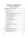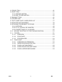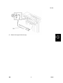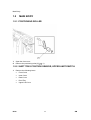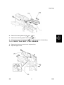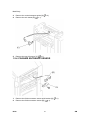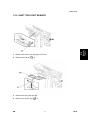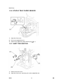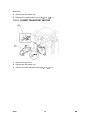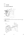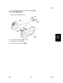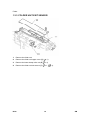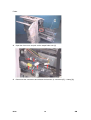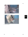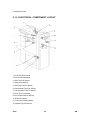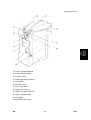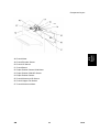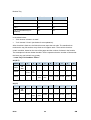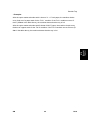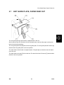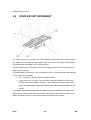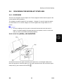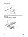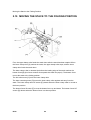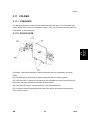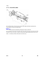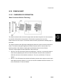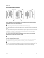
1
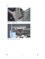
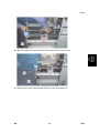
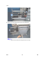
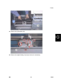
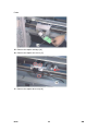
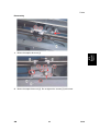
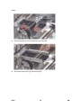
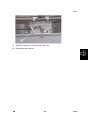
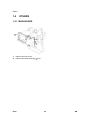
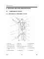
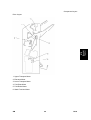
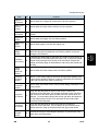
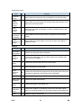
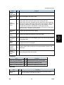
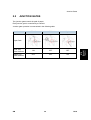
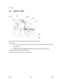
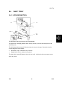
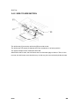
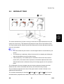
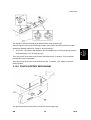
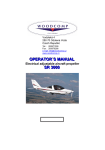
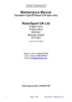
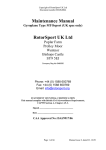
BOOKLET FINISHER
B793
BOOKLET FINISHER SR3000 REVISION HISTORY
Page
Date
Added/Updated/New
None
BOOKLET FINISHER B793
TABLE OF CONTENTS
1. REPLACEMENT AND ADJUSTMENT ............................................ 1
1.1 COVERS........................................................................................................1
1.1.1 FRONT/INNER/REAR COVERS ..........................................................1
1.1.2 UPPER COVERS .................................................................................2
1.2 MAIN BODY...................................................................................................4
1.2.1 POSITIONING ROLLER .......................................................................4
1.2.2 SHIFT TRAY POSITION SENSOR, UPPER LIMIT SWITCH ...............4
1.2.3 PROOF TRAY EXIT / FULL SENSOR..................................................5
1.2.4 FINISHER ENTRANCE SENSOR ........................................................6
1.2.5 SHIFT TRAY EXIT SENSOR................................................................7
1.2.6 STAPLE TRAY PAPER SENSOR ........................................................8
1.2.7 SHIFT TRAY MOTOR...........................................................................8
1.2.8 ENTRANCE MOTOR............................................................................9
1.2.9 UPPER TRANSPORT MOTOR ............................................................9
1.2.10 LOWER TRANSPORT MOTOR....................................................10
1.2.11 SHIFT MOTOR..............................................................................11
1.3 FOLDER ......................................................................................................12
1.3.1 STAPLE FOLDER UNIT .....................................................................12
1.3.2 FOLDER UNIT....................................................................................13
1.3.3 FOLDER UNIT EXIT SENSOR...........................................................14
1.3.4 FOLDER UNIT ENTRANCE SENSOR ...............................................15
1.3.5 STAPLER UNIT ..................................................................................15
1.4 OTHERS ......................................................................................................26
1.4.1 MAIN BOARD .....................................................................................26
1.5 DIP SWITCHES ...........................................................................................27
2. DETAILED SECTION DESCRIPTIONS......................................... 28
2.1 COMPONENT LAYOUT ..............................................................................28
2.1.1 MECHANICAL COMPONENT LAYOUT.............................................28
2.1.2 ELECTRICAL COMPONENT LAYOUT ..............................................30
2.2 JUNCTION GATES......................................................................................39
SM
i
B793
2.3 PROOF TRAY..............................................................................................40
2.4 SHIFT TRAY ................................................................................................41
2.4.1 UP/DOWN MOTION ...........................................................................41
2.4.2 SIDE-TO-SIDE MOTION ....................................................................42
2.5 BOOKLET TRAY .........................................................................................43
2.6 JOGGER UNIT ............................................................................................46
2.7 EXIT GUIDE PLATE, PAPER FEED OUT ...................................................47
2.8 STAPLER UNIT MOVEMENT......................................................................48
2.9 STACKING FOR BOOKLET STAPLING......................................................49
2.9.1 OVERVIEW ........................................................................................49
2.9.2 8.5 X 14 (LEGAL) OR SHORTER.......................................................49
2.9.3 LONGER THAN 8.5 X 14 INCHES .....................................................50
2.10 MOVING THE STACK TO THE FOLDING POSITION...........................52
2.11 FOLDER.................................................................................................53
2.11.1 OVERVIEW ...................................................................................53
2.11.2 FOLD PLATE ................................................................................53
2.11.3 FOLD ROLLERS...........................................................................54
2.12 PUNCH UNIT .........................................................................................55
2.12.1 OVERVIEW OF OPERATION.......................................................55
2.12.2 PAPER POSITION DETECTION ..................................................57
2.12.3 PUNCH UNIT MOVEMENT ..........................................................58
2.12.4 PUNCH SELECTION AND FIRING...............................................58
2.12.5 PUNCH HOPPER MECHANISM...................................................59
B793
ii
SM
Read This First
Safety and Symbols
Replacement Procedure Safety
Turn off the main power switch and unplug the machine before beginning any of
the replacement procedures in this manual.
When taking apart the bridge unit, first take the unit out of the copier.
Symbols Used in this Manual
This manual uses the following symbols.
: See or Refer to
: Screws
: Connector
: Clip ring
: E-ring
Covers
1. REPLACEMENT AND ADJUSTMENT
1.1
COVERS
B793
Booklet
Finisher
1.1.1 FRONT/INNER/REAR COVERS
1.
Remove the front cover [A] (
x 1).
2.
Remove the inner cover [B] (
x 2).
SM
1
B793
Covers
3.
Remove the rear cover [C] (
x 2).
1.1.2 UPPER COVERS
1.
Remove the upper cover [A] (
2.
Remove the proof tray [B] (
B793
x 1).
x 4).
2
SM
Covers
SM
Remove the upper left cover [C].
B793
Booklet
Finisher
3.
3
B793
Main Body
1.2
MAIN BODY
1.2.1 POSITIONING ROLLER
1.
Open the front cover.
2.
Remove the positioning roller [A] (
x 1).
1.2.2 SHIFT TRAY POSITION SENSOR, UPPER LIMIT SWITCH
1.
Remove the following items.
Front Cover
Inner Cover
Rear Cover
Proof Tray
Upper Left Cover
B793
4
SM
Main Body
2.
Remove the lower guide unit [A] (
3.
Remove the shift tray position sensor [B] (
4.
Remove the upper limit switch [C] (
x 2).
B793
Booklet
Finisher
x 4,
x 1).
x 2). (Pull it out from the assembly.)
1.2.3 PROOF TRAY EXIT / FULL SENSOR
1.
Remove the front cover, rear cover and proof tray.
2.
Open the upper cover.
SM
5
B793
Main Body
3.
Remove the vertical transport guide [A] (
4.
Remove the exit sensor [B] (
5.
Remove the tray full sensor [C] (
x 4).
x 1).
x 1).
1.2.4 FINISHER ENTRANCE SENSOR
1.
Remove the finisher entrance sensor with bracket [A] (
2.
Remove the finisher entrance sensor [B] (
B793
6
x 1).
x 1).
SM
Main Body
1.
Remove the front cover and upper left cover.
2.
Remove the link [A] (
3.
Remove the exit guide unit [B].
4.
Remove the sensor [C] (
SM
B793
Booklet
Finisher
1.2.5 SHIFT TRAY EXIT SENSOR
x 1).
x 1).
7
B793
Main Body
1.2.6 STAPLE TRAY PAPER SENSOR
1.
Open the front cover.
2.
Pull out the staple/fold unit.
3.
Remove the staple tray paper sensor [A] (
x 1).
1.2.7 SHIFT TRAY MOTOR
1.
Remove the rear cover.
2.
Open the front cover, and then pull out the staple/fold unit.
B793
8
SM
Main Body
3.
Remove the two gears [A], [B].
4.
Remove the shift tray motor [C] (
x 2,
x 1)
x 2,
x 1).
B793
Booklet
Finisher
1.2.8 ENTRANCE MOTOR
1.
Remove the rear cover.
2.
Release the belt tension [A].
3.
Remove the entrance motor [B] (
1.2.9 UPPER TRANSPORT MOTOR
1.
SM
Remove the rear cover.
9
B793
Main Body
2.
Release the belt tension [A].
3.
Remove the upper transport motor [B] (
x 2,
x 1).
1.2.10 LOWER TRANSPORT MOTOR
1.
Remove the rear cover.
2.
Release the belt tension [A].
3.
Remove the lower transport motor [B] (
B793
x 2,
10
x 1).
SM
Main Body
B793
Booklet
Finisher
1.2.11 SHIFT MOTOR
1.
Remove the rear cover.
2.
Remove the shift motor with bracket [A] (
3.
Remove the shift motor [B] (
SM
x 1,
x 4)
x 1).
11
B793
Folder
1.3
FOLDER
1.3.1 STAPLE FOLDER UNIT
1.
Remove the rear cover.
2.
Disconnect all connectors and release the harness [A] for the staple folder unit (
x 1,
x 3).
3.
Open the front cover.
B793
12
SM
Folder
4.
Pull out and remove the staple folder unit [B] (
x 2).
1.3.2 FOLDER UNIT
Remove the staple folder unit.
2.
Remove the knobs [A] (
3.
Disconnect the connectors.
4.
Remove the folder unit [B] (
B793
Booklet
Finisher
1.
SM
x 1 each).
x 4).
13
B793
Folder
1.3.3 FOLDER UNIT EXIT SENSOR
1.
Remove the folder unit.
2.
Remove the folder unit upper cover [A] (
x 1).
3.
Remove the lower clamp roller unit [B] (
x 4).
4.
Remove the folder unit exit sensor [C] (
x 1,
B793
14
x 1).
SM
Folder
B793
Booklet
Finisher
1.3.4 FOLDER UNIT ENTRANCE SENSOR
1.
Open the front cover.
2.
Pull out the staple folder unit.
3.
Remove the exit cover [A] (
4.
Remove the entrance sensor [B] (
x 2).
x 1,
x 1).
1.3.5 STAPLER UNIT
1.
Remove the rear cover.
2.
Disconnect the connector [1] and release the harness (
3.
Remove two screws [3].
SM
15
x 2 [2]).
B793
Folder
4.
Open the front cover and pull out the staple folder unit [4].
5.
Disconnect the connectors and release the harness. (4 connectors [5], 1 clamp [6])
B793
16
SM
Folder
Remove a connector [7].
7.
Remove 2 screws [8].
B793
Booklet
Finisher
6.
SM
17
B793
Folder
8.
Remove the staple tray [9].
9.
Remove the guide [10]. (2 screws)
B793
18
SM
Folder
B793
Booklet
Finisher
10. Move the stapler unit until its screw come to the hole [11] on the stay.
11. Remove the screw [12] that holds the front of the guide plate [13].
SM
19
B793
Folder
12. Remove the screw [14] that holds the rear of the guide plate.
B793
Remove the rear side screw through the hole in the stay.
20
SM
Folder
B793
Booklet
Finisher
13. Remove the guide plate [13].
14. Remove the staple folding unit [15] (3 screws, 2 connectors).
SM
21
B793
Folder
15. Remove the staple cartridge [16].
16. Remove the stapler unit cover [17].
17. Remove the stapler drive unit [18].
B793
22
SM
Folder
Reassembly
Mount the stapler drive unit [1].
2.
Mount the staple folder unit [2]. Do not tighten the screws [3] at this time.
B793
Booklet
Finisher
1.
SM
23
B793
Folder
3.
Set the special tool in the long hole [4] on both units.
4.
Secure the special tool [5] with the knob [6].
B793
24
SM
Folder
Tighten the screws [7] for the stapler folder unit.
6.
Reassemble the machine.
B793
Booklet
Finisher
5.
SM
25
B793
Others
1.4
OTHERS
1.4.1 MAIN BOARD
1.
Remove the rear cover.
2.
Remove the main board [A] (
B793
x 5).
26
SM
DIP Switches
1.5
DIP SWITCHES
SW100: Adjust the staple position for booklet mode
No.
Function
1
ON: 0.3 mm
2
ON: 0.6 mm
3
ON: 1.2 mm
4
Direction
OFF: Towards the trailing edge, ON: Towards the leading edge
SW101: Adjust the fold position
No.
Function
ON: 0.2 mm
2
ON: 0.4 mm
3
ON: 0.8 mm
4
Direction
OFF: Towards the trailing edge, ON: Towards the leading edge
B793
Booklet
Finisher
1
SW102: Move the tray position
No.
Function
1
OFF → ON → OFF
Turn the switch from off to on, then turn it to off again. Then, the tray moves down to
the shipping position
2
Not used
After you change any of these dip switch settings, open and close the finisher
cover to activate the new setting. It is not necessary to turn the main power off/on.
SM
27
B793
Component Layout
2. DETAILED SECTION DESCRIPTIONS
2.1
COMPONENT LAYOUT
2.1.1 MECHANICAL COMPONENT LAYOUT
1. Proof Tray
2. Shift Tray
3. Exit Guide Plate
4. Stack Feed Out Belt
5. Staple Unit
6. Booklet Tray
7. Proof Tray Exit Roller
8. Proof Tray Junction Gate
9. Punch Unit
10. Staple Tray Junction
Gate
11. Positioning Roller
12. 1st Clamp Roller
13. 2nd Clamp Roller
14. Folder Plate
15. Folder Roller
B793
28
SM
Component Layout
B793
Booklet
Finisher
Drive Layout
1. Upper Transport Motor
2. Entrance Motor
3. Lower Transport Motor
4. Fold Plate Motor
5. Fold Roller Motor
6. Stack Feed-out Motor
SM
29
B793
Component Layout
2.1.2 ELECTRICAL COMPONENT LAYOUT
1. Proof Tray Exit Sensor
2. Exit Guide Plate Motor
3. Shift Tray Exit Sensor
4. Upper Limit Switch
5. Shift Tray Position Sensor
6. Rear Booklet Tray Full Sensor
7. Front Booklet Tray Full Sensor
8. Proof Tray Full Sensor
9. Exit Guide Plate HP Sensor
10. Entrance Sensor
11. Front Door Safety Switch
12. Staple Tray Exit Sensor
B793
30
SM
B793
Booklet
Finisher
Component Layout
13. Proof Tray Gate Solenoid
14. Lower Transport Motor
15. Entrance Motor
16. Positioning Roller Solenoid
17. Main Board
18. Shift Tray Motor
19. Lower Limit Sensor
20. Upper Cover Sensor
21. Staple Tray Gate Solenoid
22. Upper Transport Motor
23. Shift Motor
24. Shift Motor HP Sensor
SM
31
B793
Component Layout
38. Fold Unit Exit Sensor
39. Lower Clamp Roller HP Sensor
40. Lower Retraction Motor
41. Fold Unit Entrance Sensor
42. Bottom Fence HP Sensor
43. Fold Cam HP Sensor
44. Fold Roller Motor
45. Fold Plate HP Sensor
46. Fold Plate Motor
47. Bottom Fence Lift Motor
B793
32
SM
B793
Booklet
Finisher
Component Layout
48. Punch Motor
49. Punch Encoder Sensor
50. Punch HP Sensor
51. Punch Board
52. Paper Position Sensor Slide Motor
53. Paper Position Slide HP Sensor
54. Paper Position Sensor
55. Punch Movement HP Sensor
56. Punch Hopper Full Sensor
57. Punch Movement Motor
SM
33
B793
Component Layout
Electrical Component Descriptions
Boards
Item
No.
Purpose
Main Board
17
Controls the finisher.
Punch Board
51
Controls the punch unit.
Sensors
Item
No.
Purpose
Proof Tray
Exit Sensor
1
Detects paper when it is fed out to the proof tray.
Shift Tray
Exit Sensor
3
Detects paper when it is fed out to the shift tray.
Shift Tray
Position
Sensor
5
Detects when the shift tray is at the correct height to receive paper.
Rear
Booklet
Tray Full
Sensor
6
One of two sensors that the machine uses to determine when the
booklet tray is full.
Front
Booklet
Tray Full
Sensor
7
One of two sensors that the machine uses to determine when the
booklet tray is full.
Proof Tray
Full Sensor
8
Detects when the proof tray is full.
Exit Guide
Plate HP
Sensor
9
Detects when the exit guide plate is at home position
Entrance
Sensor
10
Detects when paper comes into the finisher
Staple Tray
Exit Sensor
12
Detects paper leaving the bottom of the stapler
Lower Limit
Sensor
19
Detects when the shift tray has moved to its lowest possible position
(the shift tray is full).
Upper
Cover
Sensor
20
Detects when the upper cover is open
Shift Motor
HP Sensor
24
Detects when the side-to-side motion of the shift roller is at home
position
B793
34
SM
Component Layout
No.
Stopper S
HP Sensor
28
Detects when the ‘stopper S’ mechanism is at home position.
Stack Feed
Out HP
Sensor
29
Detects when the stack feed-out belt is at home position
Staple Unit
HP Sensor
30
Detects when the side-to-side motion of the stapler unit is at home
position
Jogger HP
Sensor
34
Detects when the jogger unit is at home position
Staple Tray
Paper
Sensor
35
Detects when paper is fed into the stapler tray
Stapler
Safety
Sensor
37
Stops side-to-side movement of the stapler until stopper S and the
stack feed-out pawl mechanisms are at home position, to prevent
damage to the machine.
Fold Unit
Exit Sensor
38
1) Detects the folded edge of the stack as it feeds out from the nip of
the fold rollers so the fold feeds back into the nip, 2) when the folded
booklet finally emerges from the nip of the fold rollers, detects the
leading and trailing edge of the booklet to make sure that it feeds out
correctly.
Lower
Clamp
Roller HP
Sensor
39
Detects when the lower clamp roller is at home position
Fold Unit
Entrance
Sensor
41
Detects 1) the leading edge of the stack during booklet stapling, and
2) also used to signal an alarm if a paper is detected at the entrance
of the fold unit when the copier is turned on.
Bottom
Fence HP
Sensor
42
Detects when the bottom fence of the booklet folding mechanism is at
home position
Fold Cam
HP Sensor
43
Along with the fold plate HP sensor, this sensor controls the
movement of the fold plate. The actuator mounted on the end of the
roller that drives the folder plate forward and back makes three full
rotations, i.e. the actuator passes the sensor gap twice and stops on
the 3rd rotation and reverses. This accounts for the left and right
movement of the fold plate.
Fold Plate
HP Sensor
45
Along with the fold plate HP sensor this sensor controls the
movement of the fold plate. The fold plate has arrived at the home
position when the edge of the plate enters the gap of this sensor.
Punch
Encoder
Sensor
49
Controls the timing for activating the punches, to punch holes in the
paper at the correct position.
SM
Purpose
35
B793
B793
Booklet
Finisher
Item
Component Layout
Item
No.
Purpose
Punch HP
Sensor
50
Detects when the hole-punch firing mechanism is at home position
Paper
Position
Slide HP
Sensor
53
Detects when the mechanism that measures the paper position in the
punch unit is at home position
Paper
Position
Sensor
54
Detects the side edge of the paper, to tell the machine where to put
the punch holes.
Punch
Movement
HP Sensor
55
Detects when the side-to-side motion of the punch unit is at home
position.
Punch
Hopper Full
Sensor
56
Detects when the punch hopper is full. Also checks if the hopper is
installed correctly.
Motors
Item
No.
Purpose
Exit Guide
Plate Motor
2
Controls the exit guide plate mechanism.
Lower
Transport
Motor
14
Controls the positioning roller, and other rollers in the finisher (see
‘Drive Layout’ for details).
Entrance
Motor
15
Controls the rollers at the entrance of the finisher.
Shift Tray
Motor
18
Moves the shift tray up and down.
Upper
Transport
Motor
22
Controls the rollers that feed paper from the junction gate to the proof
tray and to the shift tray (see ‘Drive Layout’ for details).
Shift Motor
23
Moves the shift tray from side to side.
Stack Feed
Out Motor
25
Controls the stack feed-out belt
Jogger
Motor
26
Controls the jogger in the stapler tray
Upper
Retraction
Motor
27
Controls the ‘stopper S’ mechanism. Also moves the upper clamp
roller into contact and away from the stack of paper in the stapler tray.
Upper
33
Rotates the upper clamp roller.
B793
36
SM
Component Layout
Item
No.
Purpose
Stapler Unit
Motor
36
Moves the stapler from side to side.
Lower
Retraction
Motor
40
Drives a large cam that alternately clamps and unclamps the lower
clamp roller, which is the idle roller of the clamp roller pair.
When these rollers are clamped, they are part of the paper feed path
and feed the stack toward the bottom fence of the fold unit. When the
idle roller is retracted, the stacks falls a very short distance (3 mm)
onto the fold unit bottom fence below. These rollers remain
unclamped while the bottom fence positions the stack for folding and
while the stack is folded by the fold rollers.
Fold Roller
Motor
44
Controls the rollers that fold the paper.
Fold Plate
Motor
46
Controls the plate that makes the fold in the paper.
Bottom
Fence Lift
Motor
47
Raises the bottom fence and stapled stack to the correct fold position
for the paper size.
Punch
Motor
48
Punches the holes in the paper.
Paper
Position
Sensor
Slide Motor
52
Controls side-to-side movement of the paper position sensor in the
punch unit.
Punch
Movement
Motor
57
Moves the punch from side to side.
Solenoids
Item
No.
Purpose
Proof Tray Gate Solenoid
13
Controls the proof tray junction gate
Positioning Roller Solenoid
16
Controls the positioning roller.
Staple Tray Gate Solenoid
21
Controls the staple tray junction gate
Switches
Item
Upper Limit
Switch
SM
No.
4
Purpose
Detects when the shift tray is at the highest possible position,
and cuts power to the shift tray motor.
37
B793
B793
Booklet
Finisher
Clamp
Roller Motor
Component Layout
Item
Front Door
Safety Switch
No.
11
Purpose
Cuts dc power when the front door is opened.
Others
Item
No.
Purpose
Staple Driver Unit
31
Pushes the staples into the paper.
Staple Folder Unit
32
Folds the ends of the staples after stapling
B793
38
SM
Junction Gates
2.2
JUNCTION GATES
Two junction gates control the path of paper.
Each junction gate is controlled by a solenoid.
Junction gate operation is summarized in the following table.
Mode
Proof
Shift
Staple
Proof Tray
Gate Solenoid
ON
OFF
OFF
Staple Tray
Gate Solenoid
OFF
OFF
ON
SM
39
B793
Booklet
Finisher
Paper Path
B793
Proof Tray
2.3
PROOF TRAY
Proof Tray Junction Gate Control [A]: Proof Tray Gate Solenoid
Roller Drive:
Proof Tray Exit Roller [B], Proof Tray Transport Roller [C]: Controlled by the Upper
Transport Motor
Entrance Roller [D], Transport Roller [E]: Controlled by the Entrance Motor
Jam Detection: Proof Tray Exit Sensor [F]
Tray Full Detection: Proof Tray Full Sensor [G]
B793
40
SM
Shift Tray
2.4
SHIFT TRAY
B793
Booklet
Finisher
2.4.1 UP/DOWN MOTION
The shift tray motor [A] moves the tray up and down.
The upper limit switch [B] detects when the tray moves up too far, and cuts power to the
shift tray motor.
The shift tray position sensor [C] checks when the tray (or the top of the stack) is at the
correct height to receive paper.
Shift Mode: This is checked every 5 sheets
Staple Mode: This is checked every stack
The lower limit sensor [D] detects when the tray is full. At this point, the tray cannot move
down any more.
SM
41
B793
Shift Tray
2.4.2 SIDE-TO-SIDE MOTION
The shift motor [A] moves the shift roller [B] from side to side.
The shift motor HP sensor [C] detects when the mechanism is at home position.
The upper transport motor rotates the shift roller.
When shift mode is used, the shift motor turns on after each page is fed out. Then, for the
next set, the shift motor turns the other way. In this way, the user can easily divide the sets.
B793
42
SM
Booklet Tray
BOOKLET TRAY
B793
Booklet
Finisher
2.5
The sensor actuator arm [A] rests on the top of the stack of stapled booklets as they are
output to the lower tray. A flap depressor [B] keeps the open ends of the booklets down.
The front booklet tray full sensor [C] and rear booklet tray full sensor [D] detect when the
tray is full of booklets.
The front booklet tray full sensor is mounted higher than the rear booklet tray full
sensor.
The booklet tray is stationary. When it becomes full, the stapling and folding job
stops until booklets are removed from the tray.
If the booklet tray is not installed (this is detected if the front and rear sensors
remain OFF), the machine will not operate in the booklet staple and fold mode.
When booklet mode is selected, the tray full message appears on the operation
panel.
The combinations of the two actuators and two sensors when the actuator arm rises
determines the number of booklets that the tray can hold before the job stops.
Tray full detection depends on the size of the paper and the number of sheets in one
stapled and folded booklet.
The condition detected by the machine (
Ready
Full 1,
Full 2,
Full 3; see the
illustration above) depends on the states of the sensors, as shown in the table below.
SM
43
B793
Booklet Tray
Condition
Front Sensor
Rear Sensor
Ready
ON
OFF
Full 1
ON
ON
Full 2
OFF
ON
Full 3 (or booklet tray not
installed)
OFF
OFF
In the tables below:
"Sht" denotes "sheets in a stack".
"Cnt" denotes "Count" (see below for an explanation).
After a booklet is feed out, the fold roller motor stops the exit roller. The machine then
monitors the tray full sensors every feed-out of a paper stack. The machine checks a
certain condition, based on the size of the paper and the number of sheets in the booklet.
Two examples are shown below the table. Tell the operators that the number of sheets that
the lower tray can hold will vary greatly.
- Lower Tray Full Condition Tables A3 (DLT)
Sheet
1
2
3
4
5
6
7
8
9
10
Full 1
15
Cnt
-
-
-
-
-
-
-
-
-
Full 2
-
3 Cnt
11
Cnt
-
-
-
-
-
-
-
Full 3
-
-
-
16
Cnt
12
Cnt
2 Cnt
3 Cnt
5 Cnt
6 Cnt
7 Cnt
Sheet
1
2
3
4
5
6
7
8
9
10
Full 1
15
Cnt
-
-
-
-
-
-
-
-
-
Full 2
-
8 Cnt
16
Cnt
19
Cnt
5 Cnt
2 Cnt
2 Cnt
2 Cnt
3 Cnt
4 Cnt
Full 3
-
-
-
-
-
-
-
-
-
-
A4 (LT)
B793
44
SM
Booklet Tray
- Examples After the copier makes a booklet with 1 sheet of 11 x 17 inch paper, the machine checks
every feed-out of a paper stack for the ‘Full 1’ condition. If the Full 1 condition occurs 15
times (‘15 Cnt’ in the table above), the machine detects that the tray is full.
After the copier makes a booklet with 5 sheets of A4/LT paper, the machine checks every
feed-out of a paper stack for the ‘Full 2’ condition. If the Full 3 condition occurs 5 times (‘5
B793
Booklet
Finisher
Cnt’ in the table above), the machine detects that the tray is full.
SM
45
B793
Jogger Unit
2.6
JOGGER UNIT
The jogger is used in corner-staple mode and in booklet mode.
For each sheet of paper when it arrives in the staple tray, the following is done.
The jogger motor [A] drives the jogger fences [B].
The positioning roller solenoid moves the positioning roller [C] onto the top of the sheet.
Then the lower transport motor turns on and the positioning roller rotates to push the
sheet of paper against the stopper (there are two stoppers: stopper L or stopper S the
one that is used depends on the paper size, as we shall see later.)
The jogger HP sensor [D] detects when the jogger fences are at home position (away from
the stack).
The staple tray exit sensor [E] detects if a jam occurs when the machine feeds the stack out
at the bottom of the jogger tray.
B793
46
SM
Exit Guide Plate, Paper Feed Out
EXIT GUIDE PLATE, PAPER FEED OUT
B793
Booklet
Finisher
2.7
The exit guide plate [A] opens when a stapled stack is fed out.
Also it opens every time a sheet is fed to the staple tray, to prevent the paper running into
the exit roller during stacking.
The exit guide plate motor [B] drives the exit guide plate. The exit guide plate HP sensor [C]
detects when the guide plate is at home position.
The stack feed-out belt feeds out stapled stacks. The pawl [D] on the belt moves the stack
out to the exit.
The stack feed-out motor [E] drives the belt. The stack feed-out HP sensor [F] detects when
the belt is at home position.
SM
47
B793
Stapler Unit Movement
2.8
STAPLER UNIT MOVEMENT
The machine has only one stapler [A]. It does stapling for booklets and for corner stapling.
The stapler unit motor [B] moves the stapler from side to side. The stapler unit HP sensor
[C] detects when the stapler unit is at home position.
In corner staple mode, at the start of the job, the stapler moves to the position where the
stapler will be inserted.
In booklet mode, at the start of a job, the stapler moves to a starting position that depends
on the paper size, as follows:
8.5 x 14 inches or shorter: Rear side staple position
Longer than 8.5 x 14 inches: Center position. When the stapler is at the center
position, bracket [E] releases ‘stopper L’, which catches the bottom edge of the
paper for booklet stapling with longer paper sizes. This will be described in a later
section.
If the stapler safety sensor [D] detects the stapler unit at its initialization, the stapler unit
stops moving until the stack feed out belt pawl and stopper S are at home position. If the
stapler unit does not stop, it could collide with the pawl and/or the stopper.
B793
48
SM
Stacking for Booklet Stapling
2.9
STACKING FOR BOOKLET STAPLING
2.9.1 OVERVIEW
There are two stoppers near the stapler unit. These stoppers hold the stack of paper in the
correct position during stacking.
The stoppers are called ‘stopper S’ and ‘stopper L’. Stopper S is used for legal size paper,
or shorter than 8.5 x 14 inches. Stopper L is used for paper that is longer than 8.5 x 14
inches.
In corner stapling mode, the pawl on the stack feed-out belt holds the stack of
paper. For booklet stapling, this pawl stays at home position, which is on the rear
side, so it does not interfere with booklet stapling.
B793
Booklet
Finisher
2.9.2 8.5 X 14 (LEGAL) OR SHORTER
At the start of the set, the upper retraction motor [A] turns on, and stopper S [B] moves
down into position to catch the paper
. The upper retraction motor also moves the upper
clamp roller [C] into contact with the stack
.
SM
49
B793
Stacking for Booklet Stapling
When the stack is complete, stopper S moves away [D], and the machine feeds the stack to
the correct position for stapling. To do this, the upper clamp roller motor [E] rotates the
upper clamp roller.
2.9.3 LONGER THAN 8.5 X 14 INCHES
At the start of the set, the stapler moves to the center position. At this position, a bracket [A]
on the stapler unit pushes stopper L [B]. The pawl [C] on the stopper L assembly then
moves into position to catch the paper. The upper clamp roller holds the stack (see the
B793
50
SM
Stacking for Booklet Stapling
previous section).
When the stack is complete, the stapler moves to the rear-side position, and stopper L
B793
Booklet
Finisher
moves away. The machine feeds the stack to the correct position for stapling.
SM
51
B793
Moving the Stack to the Folding Position
2.10 MOVING THE STACK TO THE FOLDING POSITION
First, the upper clamp roller feeds the stack down after the stack has been stapled. When
the lower clamp roller [A] catches the stack, the upper clamp roller stops, and the lower
clamp roller feeds the stack down.
The lower clamp roller is released just before the leading edge of the stack reaches the
bottom fence [B] (this fence consists of two pawls that catch the paper). The bottom fence
moves the stack to the folding position
The fold roller motor [C] turns the lower clamp roller.
The lower retracting motor [D] moves the lower clamp roller against and away from the
stack. The lower clamp roller HP sensor [E] detects when the lower clamp roller is moved to
the home position.
The bottom fence lift motor [F] moves the bottom fence up and down. The bottom fence HP
sensor [G] detects when the bottom fence is at home position.
B793
52
SM
Folder
2.11 FOLDER
2.11.1 OVERVIEW
The fold plate pushes the stack into the nip between the fold rollers. The fold rollers feed
out the stack, then reverse to feed it back in again. Then, the fold rollers feed the stack out
of the folder, to the booklet tray.
B793
Booklet
Finisher
2.11.2 FOLD PLATE
[A]: Bottom Fence Stack Stoppers. Catches the stack after it is released by the clamp
rollers.
[B]: Fold Plate Motor. Drives the timing belt and gears that move the fold plate.
[C]: Fold Plate Cam. Controls the movement of the fold plate to the left (into the nip of the
fold rollers) and right (toward the fold plate home position).
[D]: Fold Plate HP Sensor. Controls operation of the fold plate motor.
[E]: Fold Plate. Moves left and pushes the stack into the nip of the fold rollers and then
moves right to retract.
SM
53
B793
Folder
2.11.3 FOLD ROLLERS
[F]: Fold Roller Motor. Drives forward to feed out the stack at the fold, and then drives
forward again to feed out the folded stack.
This cycle can be repeated by changing the setting of SP6136.
[G]: Fold Rollers. Driven by the fold roller motor, this roller pair feeds out the stack at its fold,
reverses to feed in the stack to, and then feeds forward again (assisted by the fold unit exit
rollers – not shown) to feed out the stack to the lower tray.
B793
54
SM
Punch Unit
2.12 PUNCH UNIT
2.12.1 OVERVIEW OF OPERATION
The finisher entrance roller corrects for paper skew and then the punch unit moves across
to punch the holes at the correct position. Each sheet is punched one at a time.
Paper feeds out of the copier. The finisher entrance sensor [A] detects the leading edge of
the sheet.
The finisher entrance roller [B] stops rotating briefly while the copier exit rollers continue to
rotate. This buckles the paper against the finisher entrance roller to correct skew. The
finisher entrance roller starts to rotate again and feeds the sheet into the finisher.
These SP codes adjust the skew operation in the punch unit:
SP6130. This SP corrects the punch hole alignment. To do this, it corrects the skew of
each sheet by adjusting the amount of time the finisher entrance roller remains off
while the exit roller of the machine remains on. For more, see Section "5. Service
Tables".
SP6131. This SP determines whether the finisher entrance roller stops to correct skew
when paper enters the finisher. You can use this SP to disable the skew correction. For
more, see Section "5. Service Tables".
SM
55
B793
B793
Booklet
Finisher
Skew Correction Before Punching
Punch Unit
Punch Unit Position Correction
These operations (skew correction before punching, and punch unit position correction)
increase the accuracy of the punch alignment.
The trailing edge of the sheet passes the finisher entrance sensor [A].
The paper position slide unit moves the paper position sensor [B] forward to the edge of the
paper.
The paper position sensor detects the position of the paper edge and sends this information
to the punch unit board. The machine uses the detected position of the paper edge to
calculate the correct position for punching.
The upper transport motor switches on and rotates the feed rollers [C] the prescribed
distance to put the paper under the punch unit [D].
Using the result of the position calculation, the punch unit control board moves the punch
unit [D] to the adjusted punch position.
The paper position slide unit and its paper sensor, move back to the paper position slide
home position sensor [E], and the punch unit fires the punches to make the holes.
The feed rollers feed the punched paper out of the punch unit and into the paper path. The
punch unit moves back to home position (detected by the home position sensor [F].
B793
56
SM
Punch Unit
These SP codes adjust the punch hole alignment:
SP6128 Adjusts the punch positions in the direction of paper feed.
SP6129 Adjusts the punch position perpendicular to the direction of feed.
For more, see Section "5. Service Tables".
B793
Booklet
Finisher
2.12.2 PAPER POSITION DETECTION
The paper position sensor slide motor [A] extends and retracts the paper position slide that
holds the paper position sensor [B].
The paper position sensor detects the position of the paper edge. The detected position of
the paper is used to move the punch unit across to the correct position for punching.
When the paper position slide is retracted, the paper position slide HP sensor [C] detects
when the slider is at home position and stops paper position slide motor.
SM
57
B793
Punch Unit
2.12.3 PUNCH UNIT MOVEMENT
The punch movement motor [A] extends and retracts the punch unit to put it at the correct
position for punching.
The punch movement HP sensor [B] detects the position when it retracts, switches off the
punch movement motor, and stops the punch unit at its home position.
The punch drive motor [C] fires the punches that punch holes in the paper below.
2.12.4 PUNCH SELECTION AND FIRING
The punch drive motor [A] turns the small, notched encoder wheel [B] through the gap in
the punch encoder sensor [C]. The sensor output is used to control the punch timing.
B793
58
SM
Punch Unit
The timing for 2-hole punching [E] is different from 3-hole punching [F].
When the punch unit is at the punching position, the punch motor turns until the encoder
This is the ‘1’ position in the diagrams (the first diagram is for 2-hole punching, and the
second diagram is for 3-hole punching).
Then, the punch drive motor turns counter-clockwise to the ‘2’ position. This movement
punches the holes in the paper.
Then, the punch drive motor turns clockwise to the ‘1’ position, to be ready for the next
sheet of paper.
2.12.5 PUNCH HOPPER MECHANISM
The punchouts fall from the punch unit into the punch hopper [A].
SM
59
B793
B793
Booklet
Finisher
detects the starting position for 2-hole or 3-hole punching.
Punch Unit
The punch hopper full sensor [B] does the following:
Signals that the hopper is full when it detects the top of the stack of punchouts that
have collected in the hopper.
Detects when the punch hopper is set properly.
B793
60
SM