1
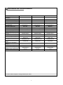
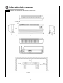
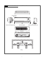
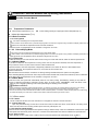
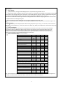
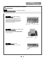
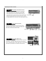
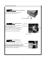
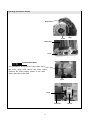
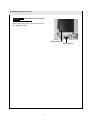
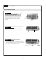
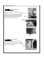
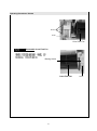
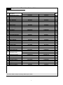
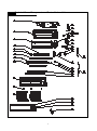
SERVICE MANUAL
FREE COMBI SERIE
FC-H07AIN, FC-H09AIN, FC-H12AIN
2
Specifications and Technical Parameters
Model
Fan Motor Speed (r/min)
(SH/H/M/L)
Output of Fan Motor (w)
Input Power of Heater (w)
Fan Motor Capacitor (uF)
Fan Motor RLA(A)
Fan Type-Piece
Diameter-Length (mm)
Evaporator
Pipe Diameter (mm)
Row-Fin Gap(mm)
Coil length (l) x height (H) x coil
width (L)
Swing Motor Model
Output of Swing Motor (W)
Fuse (A)
Sound Pressure Level dB (A)
(H/M/L)
Sound Power Level dB (A)
(H/M/L)***
Dimension (W/H/D) ( mm)
Dimension of Package (L/W/H)(
mm)
Net Weight /Gross Weight (kg)
FC-H07AIN
FC-H09AIN
FC-H12AIN
1150/1050/900/750
1150/1050/900/750
1250/1050/950/800
20
20
20
/
/
/
1
1
1
0.26
0.26
0.26
Cross flow fan – 1
Cross flow fan – 1
Cross flow fan – 1
Ø97×583
Ø97×583
Ø92×616
Aluminum fin-copper tube
Aluminum fin-copper tube
Aluminum fin-copper tube
Ø7
Ø7
Ø7
2-1.4
2-1.4
2.5.-1.4
580X228.6X25.4
580X228.6X25.4
681X324.3X38.1
MP28VB
MP28VB
MP28EC
2
PCB 3.15A
Transformer 0.2A
2
PCB 3.15A
Transformer 0.2A
2
PCB 3.15A
Transformer 0.2A
37/34/31/28
38/34/31/28
40/34/32/30
47/44/41/38
48/44/41/38
50/44/42/40
770X250X190
770X250X190
830X285X200
855X330X272
855X330X272
906X385X265
8.5/12.5
8.5/12.5
11/14
The above data is subject to change without prior notice.
2
Parts name
Front panel
air in
display
Indoor unit
Guide louver
air out
wrapping tape
Power supply
Display enlarged diagram
temperature setting
Remote controller
Heating
Plug
cooling
Outdoor unit
auto
power supply/running
Water drainage hose
Air outlet
dry
Remote controller receiver window
Air in
connection
pipe and
connection
line
air out
3
Outline and installation dimensions
Outline and installation dimensions of indoor unit
Air inlet grid
Mark for left outlet pipe hole
Top view diagram
Back view
Ceiling
4
Mark for right outlet pipe hole
Outline and installation dimensions of indoor unit
Air inlet grid
Mark for left outlet pipe hole
Top view diagram
Back view
Ceiling
5
Mark for right outlet pipe hole
5 Circuit diagram
FC-H07AIN FC-H09AIN FC-H12AIN
,
The above circuit diagram is subject to change without prior notice, please refer to nameplate for reference.
6
6
Controller Function Manual and Operating Instructions
Controller Function Manual
6.1.1
◆
Temperature Parameters
Indoor preset temperature (Tpreset)
Indoor heating exchanger copper pipe exterior temperature(Tpipe)
◆ Indoor tube temperature (Ttube)
6.1.2 Basic Functions
6.1.2.1 Cooling Mode
fan motor and swing runs on the preset mode,
When outdoor unit has mulfunction or protection stopping,indoor unit continue to original running condition,and display mulfunction code.
Indoor fan motor will be stoped when there has mode confliction
Under this mode, the temperature can be set within a range from 16 to 30℃.
6.1.2.2
Dehumidifying Mode
Fan motor runs on the low fan speed,swing runs on the preset mode,
When outdoor unit has mulfunction or protection stopping,indoor unit continue to original running condition,and display mulfunction code.
Under this mode, the temperature can be set within a range from 16 to 30℃.
6.1.2.3
Fan mode
I
Indoor fan motor just run under the fan mode.Unit is running cool mode with auto fan under the auto fan speed mode.
6.1.2.4 Heating Mode
(1) In HEAT mode, when the compressor is running indoor unit turns to prevent cold wind; when the compressor is
stop ,indoor fan motor is on,then indoor unit turns to blow residual heat .
(2)Protect function, when the compressor is stopped by malfunction, the indoor fan will run to blow residual heat .
3).Prevent cold wind: the compressor starts to run, the indoor fan will run after 2min.
4).Blow residual heat
After the indoor fan blow 60s,the unit will turn off. During blowing residual heat,the fan speed is unchangeable.
When defrosting\backing-oil,indoor fan motor stop,unit don't blow residual heat,unit don't check all temp. sensor malfunction
Under this mode, the temperature can be set within a range from 16 to 30℃.
6.1.2.5Auto Mode
Under this mode, the system will automatically select its run mode (cooling, dehumidifying, heating or fan) with the
change of ambient temperature. Protection function same as under COOL, DEHUMIDIFY, FAN and HEAT mode.
during the unit is defrosting \backing oil till unit stop defrosting and backing oil fro 3 minutes
Modes confliction
If indoor received the information modes confliction position 1 of outdoor unit, indoor unit overload will stop (Indoor fan motor, swing),
malfunction indication will be displayed, the mode sent to outdoor unit is still the mode that received by the remote control.
If timer on has arrived, if indoor received the information modes confliction position 1 of outdoor, indoor overload (indoor fan motor,swing)
, the malfunction display, the mode sent to outdoor unit is still the mode that recived by the remote control.
6.1.3 Other control
6.1.3.1 Buzzer
The air conditioner will send out “Hua” alert when it is energized or receives a control command.
6.1.3.2 AUTO STOP key
Upon one press of this key, the unit will run under auto mode, the indoor fan will run under auto fan. The swing motor
works when the indoor fan is working. Another press of this key will stop the unit.
6.1.3.3 Auto fan speed control
Indoor fan motor choose high\middle\low fan speed according to ambient temp. under the cool\heat\fan mode,anto fan speed
is low speed under dehumidify mode.There has 3 minutes and a half between the switchs of different fan speed at least.
6.1.3.4. Sleep Function
Setting SLEEP function under COOL or DRY mode, the preset temperature will automatically rise by 1
7
after 1
hour and rise by another 1℃after 2 hours. Preset temperature will rise by 2 ℃in total within 2 hours. After that, the unit will
run at this preset temperature and at preset fan speed.
Setting SLEEP function under HEAT mode, the preset temperature will automatically decrease by 1 ℃ after 1hour and
decrease by another 1℃ after 2 hours. Preset temperature will decrease by 2 ℃ in total within 2 hours. After that, the
unit will run at this preset temperature and at preset fan speed.
Preset temperature for AUTO mode and FAN mode , the sleep function will remain unchanged.
Timer function
1.Ordinary Timer setting:
Timer on: Under unit off, the timer on function could be set up, if timer on has arrived, controller will run at
setting mode, the timer interval is 0.5hr, setting range is 0.5-24hrs
.
Timer off: Under unit off, the timer off function could be set up, if timer off has arrived, controller will run at
setting mode, the timer interval is 0.5hr, setting range is 0.5-24hrs.
2.Timer setting for hour
Timer on: if system is running, to set timer on, the system will continue to run, if unit is off to set up timer on,
when timer on has arrived, the system will run at pressetting mode.
Timer off: If system is off to set up the timer off, when to set up timer off, the unit will stand by, when unit is on,
to set up timer off, when the timer off arrived, the system will stop to work.
Timer setting change:
When system is in Timer status, can set up timer on and timer off by wireless remote control, to reset up Timer
also, the system will run at last setting status.
When system is running, at the same time to set up Timer on and Timer off, the system will keep the present
setting status, when time arrived, system will stop to work.
When system stop, at the same time to set up Timer on and Timer off, the system will stop, untile the timer
arrived, the system will start to work.
Hereafter, when timer of timer on in every day arrived, it will run the presetting modes, after timer off arrived,
the system will stop.
3.6 Memory function
Memory contents: Mode, up and down swing, Light, Setting temp., Setting fan speed, Ordinary setting
Fahrenheit/Centigrade, after powered off, and powered on, it will run at the memory contents.
If no timer setting function in last remote control order, the system will memorize the last remote control
order, the system will memorize the last remote control order and work with last remote control setting.
In the last remote control order, there is ordinary timer function, if power off happen beffore the timer
arrived, the system will memorize the last remote control timer function, and will recalculate.
If there is timer function in last remote control order, but timer has arrive, system will run at timer on or timer
off and power off, after repowered on, the system will run at the mode before power off.
I Feel function
When controller received the orders that the controller will work according to ambient temperature which is sent by remote control (Except
Defrost and anti-cool wind, it will still adopt the air conditioner self ambient sensor sampling value), the remote control in every 10mins, to
sent the ambient temperature value to controller. 11mins later, the controller haven't received the ambient temperature value from the
remote control that the air conditioner will run itself ambient temperature. If there is no setting function that the ambient temperature will
adopt the AC sensor sampling value. Power off will not memorize this function.
Turbo function
The turbo function is available in Cool and Heat modes. When
d
controller received this order, the indoor fan will run at super
high, sent the outdoor unit Turbo signal and sent the high fan speed.
UP\Down swing fan function
After powered on, the up and down swing motor will firstly rotate the air guide baord to position O in anticlockwise, turn off the air vent.
After unit is turned on, if there is no siwng function set up, under the Heat mode or Auto Heat Heating angle
Cooling angle
mode, the up and down air guide board will rotate to position D in clockwise; In other modes, the
Angle
Angle
up and down guide board will roate to horizontal position L1 clockwise. When turning on the unit
to set up swing function synchronously. If unit is turned on to set up the swing function that the
guide louver will swing between L and D. There are 7 kinds of status of swing for guide louver:
Position L, Position A, Position B, Position C, Position D, Position L and Position D, Position L
to Position D to stop swing (the inclination between L-D is conformal). When unit is off the air
guide louver will close and turn to position 0. The swing is only valid while setting swing order
and indoor fan motor is running.
Cold plasma function
When turn on fan motor can turn on cold plasma function; when remote control to turn off the
cold plasma function or turn off fan motor, this function is turned off. (Only the unit of Panel 1
has this function)
8
Displayer
Basic display
After powered on, the figure will be displayed, then only Power/running indicator turn on.
When using remote conroller to open the unit, it will turn on, at the same time to display current setting running modes.
Cool mode:run and cool lights are green; Heat mode: run and heat lights are green;Dry mode:run and dry lights are green
Fan mode:run and fan lights are green; Auto mode: run\auto and actual run lights are green; is green
Note: Panel 2 models don't have fan light and auto mode light.Under the fan mode run light is green.Under the auto mode
run lightand actual run mode light are green.
If you turn off light key, then all display will be turned off(it's available under the unit is off)
(4) After set up the SLEEP function, the displayer will keep original displaying status that is Sleep function will not affect the light on and
Off.
Dual 8 display
The nixie tube will display current setting temperature that the setting temperature range is 16-30 . In Auto mode, the Cool and Fan will
display 25 , in Heat will display 20 , cooling only controller only display 25 . Display indoor temperature, the temperature setting range
is 0 to 60 .
Fan speed display
Fan speed signal is divided into 3 parts dynamic circularly display, the three parts are two section, four section and six full display,
there into the two section is still displayed. When remote control the super high speed, the fan speed figure blinks quickly; when
remote control low fan speed, the figure blinks slowly; When remote control the middle fan it will display speed is between the
high speed and low speed; When remote control the auto speed, the figure blinks depends on the inner fan motor actual running
speed. If indoor unit stops running that will blink with the lowest speed display.
Note: Export unit with panel 2 haven’t this fan speed display.
Indoor unit malfunction display
Dual 8 display Running light Heating light Cooling light
Malfunction
System abnormal (anti-high temp,
unit will stop, cooling overload)
Blink 4 times
H4
Blink 3 times
Compressor overload protection
Modes protection
Blink 5 times
High pressure protection
Blink once
Anti-freeze protection unit will stop
Blink twice
Air exhaust tempeature protection
Blink 4 times
Low voltage overcurrent protection
Blink 5 times
Modes confliction
Blink 7 times
Communication malfunction
Blink 6 times
Blink once
Defrost or heating oil return
Indoor ambient temp sensor opened,
short circuit
Any of indoor evaporator sensor opened,
short circuit
Blink once
Blink twice
Outdoor ambient sensor opened, short circuit
Blink 3 times
Outdoor condensor sensor opened, short circuit
Blink 4 times
Outdoor air exhaust sensor opened, short circuit
Blink 5 times
Start up failure
Blink 7 times
Blink 6 times
PFC malfunction
Blink 14 times
Compressor demagnetization protection
The following malfunction need to use remote control for transf er, within 3s continuously press
SLEEP button for 6 times will display, 5min will automatically quit detection status
(invalid in Auto mode) or within 3s continuously press SLEEP button for 6 times will quit.
Over current frequency decline
Blink 6 times
Whole unit over current frequncy decline
Blink 8 times
Compressor air exhuast frequncy decline
Blink 9 times
Whole unit AC current voltage decline frequency
decline
Heating anti-high temperature frequency decline
Blink 10 times
Blink 10 times
Anti-cool wind protection
Blink 9 times
Blink 7 times
Cooling oil return
Note: If several malfunction exist synchronously, the malfunction code will display circularly. Indicator will blink 0.5s and extinguish 0.5s.
Defrosting. oil reutrn procedure, and quit within 3mins, will not detect indoor unit all sensor malfunction.
9
Trendy Series
7
Disassembly and Assembly Procedures
7
Disassembly Procedures of Indoor Unit for panel 1
Operating Procedures / Photos
7
Disassemble Front Panel
Lift the front panel upward. Firstly, screw off a screw
fixing the upper protection plate at the receiving
window and remove the protection plate. Then, pull
away the connection terminal. Pull the panel outward
with force along the groove fixing the panel of the
panel body to remove the panel
Connecting terminal
Protection plate
groove Panel
7
Disassemble Cope of Electric Box
Firstly, screw off the screw fixing the cope of electric box,
open the cope of electric box, loose the clasp and remove
the cope of electric box.
the cope of electric box.
7
Disassemble Filter
Push the filter inward, and then pull it upward to
remove it.
Filter
14
10
clasp
Screws
Operating Procedures / Photos
Disassemble Lower Guide Louver
Manually bend the lower guide louver to loose the
clasp at the guide louver. Remove the lower guide
louver.(Note:to remove the upper guide louver,you
must open the front case first, then screw off the screws Guide Louver
clasp
fixing the upper guide louver and the water tray , bend
the upper guide louver and remove the upper guide louver)
Disassemble Front Case
Unscrew the three screw covers at the front case,
unscrew the three screws, pull open the clasp at the
front case, and remove the front case.
screw covers
clasp
screws
sensor
front case
Disassemble Water Tray
Screw off the fixing screws fixing the water tray with a
screw driver. Loose the clasp at the other end and pull
out the terminal board of the step motor. Pull upward
the water tray and take it out. Remove the water tray.
Water Tray
11
terminal
screws
Operating Procedures / Photos
Disassemble Cover of Electric Box
Loosen the three clasps, and pull upward to
remove the cover of the electric box.
cover of the electric box
clasp
Disassemble Electric Box
room sensor
pipe temp. sensor
Remove the grounding wire of the evaporator.
grounding wire
Take out the pipe temp. sensor.
Unplug the plugging connector of the indoor motor
at the electric box, use screwdriver to
unscrew the screw fixing the electric box,
loose the clasp and remove the electric box.
plugging connector
Disassemble Evaporator
Unscrew the screw fixing the rear pipe clamp to
Unscrew the screws fixing the evaporator, one on the screw
left and two on the right. Manually lift the evaporator
and release the side clasp of the evaporator from the
groove.Carefully take out the evaporator and pay rear pipe clamp
attention to protect the connecting pipe.
12
screw
clasp
Operating Procedures / Photos
Evaporator
screw
clasp
Evaporator
screw
Disassemble Motor
Use screwdriver to unscrew the two screws fixing
motor clamp
the motor clamp, and remove the motor clamp.
Unscrew the three holding screws at the shaft
sleeve, and remove the motor.
screw
screw
Axial fan
13
Motor
Operating Procedures / Photos
Disassemble Cross Flow Fan
After remove the motor, pull out it from the
left bearing holder.
Cross Flow Fan
Bearing Holder
14
Disassembly Procedures of Indoor Unit for panel 2
Operating Procedures / Photos
Disassemble front panel and filter
Open the panel,screw off screws fixing the cover
of electric box,pull away the electric box.Pull the
panel outward with force along the groove fixing
the panel of the panel body to remove the panel
Panel
Push the filter inward, and then pull it upward to
remove it.
Filter
Disassemble Lower Guide Louver
Manually bend the lower guide louver to loose the
clasp at the guide louver. Remove the lower guide
louver.
Guide Louver
clasp
Disassemble Front Case
Unscrew the three screw covers at the front case,
unscrew the three screws, pull open the clasp at the
front case, and remove the front case.
screw covers
15
screws
front case
Operating Procedures / Photos
Disassemble Cover of Electric Box
cover of the electric box
Loosen the three clasps, and pull upward to
remove the cover of the electric box.
clasp
Disassemble Water Tray
Screw off the fixing screws fixing the water tray with a
screw driver. Loose the clasp at the other end and pull
out the terminal board of the step motor. Pull upward
the water tray and take it out. Remove the water tray.
terminal
Water Tray
screws
pipe temp. sensor
Disassemble Electric Box
Remove the grounding screws of the evaporator.
Take out the indoor temp. and pipe temp. sensors.
Unplug the plugging connector of the indoor motor
at the electric box, use screwdriver to
unscrew the screw fixing the electric box,
loose the clasp and remove the electric box.
16
grounding screw
room sensor
screw
Operating Procedures / Photos
Disassemble Evaporator
Unscrew the screw fixing the rear pipe clamp to
remove it.
rear pipe clamp
Unscrew the screws fixing the evaporator, one on the
left and two on the right. Manually lift the evaporator
and release the side clasp of the evaporator from the
screw
groove.Carefully take out the evaporator and pay
attention to protect the connecting pipe.
Evaporator
screw
screw
Disassemble Motor
Use screwdriver to unscrew the two screws fixing
the motor clamp, and remove the motor clamp.
Unscrew the three holding screws at the shaft
motor clamp
sleeve, and remove the motor.
screw
17
Operating Procedures / Photos
Screw
motor
Cross Flow Fan
Disassemble Cross Flow Fan
Bearing Holder
Cross Flow Fan
18
Screw
PARTS GUIDE
FREE COMBI SERIE
FC-H07AIN, FC-H09AIN, FC-H12AIN
FC-H07AIN, FC-H09AIN, FC-H12AIN
8
Exploded View and Components and Parts List
Exploded View of Components and Parts of Indoor Unit
2
Components and Parts List of Indoor Unit
No
Description
1
2
3
4
5
6
7
8
9
10
11
12
13
14
15
16
17
18
19
20
21
22
23
24
25
26
27
28
29
Wall-Mounting Frame
Rear Case
Evaporator Assy
Cross Flow Fan
Ring of Bearing
/
Drainage Pipe
Water Tray
Swing Louver
Swing Linkage 1
Swing Linkage 2
Front Case
Front Panel
Decorate piece
Remote control YT1F
Filter
Receiver Board D5K3
Screw Cover
Guide Louver 1
Guide Louver 2
Motor MP28VB
Motor Clamp
Motor FN20E-PG
Electric box cover
Covering plate
Terminal board T4B3A
Electric box
Main PCB M803F2AJ
Room Sensor15K
30
Tube Sensor 20K
31
32
33
34
35
36
37
38
39
Jumping Connector
Transformer 48X26J
Wire clamp
Rear clamp
Connecting Cable
swing louver clamp
swing louver
swing louver(up)
swing louver(down)
Part Code
FC-H07AIN
01252220
222020012
010020531
10352001
76512203
/
0523001401
201820271
10512032
10582002
10582003
20002215
200023353
68012019
30510049
111200511
30545041
24252006
10512033
10512034
15012086
26112014
150120761
20122082
20112058
42011233
20112057
30038004
390000451
3900019814
3900019815
3900019816
4202300101
43110261
71010253
24242001
400204056
10582409
10582408
10542004
10542005
The above data is subject to change without prior notice.
3
FC-H09AIN
01252220
222020012
010020531
10352001
76512203
/
0523001401
201820271
10512032
10582002
10582003
20002215
200023353
68012019
30510049
111200511
30545041
24252006
10512033
10512034
15012086
26112014
150120761
20122082
20112058
42011233
20112057
30038004
390000451
3900019814
3900019815
3900019816
4202300102
43110261
71010253
24242001
400204056
10582409
10582408
10542004
10542005
Qty
1
1
1
1
1
/
1
1
12
1
1
1
1
1
1
2
1
3
1
1
1
1
1
1
1
1
1
1
1
1
1
1
1
1
1
1
1
1
1
1
1
Exploded View of Components and Parts of Indoor Unit
4
Components and Parts List of Indoor Unit
No
Description
1
2
3
4
5
6
7
8
9
10
11
12
13
14
15
16
17
18
19
20
21
22
23
24
25
26
27
28
29
30
31
32
33
34
35
36
Wall-Mounting Frame
Rear Case
Evaporator Assy
Cross Flow Fan
Ring of Bearing
\
Drainage Pipe
Water Tray
Swing Louver
Swing Linkage
Front Case
Screw Cover
Filter
Remote Control YT1F
Decorate Piece
Receiver Board
Front Panel
Guide Louver
Guide Louver
Motor MP28EC
\
\
Right Motor Clamp
Bearing Holder
Motor FN20J-PG
Electric Box Cover
Terminal Board T4B3A
Covering Plate
Electric Box
Main PCB M803F2J
Transformer 48X26J
Wire Clamp
Rear Clamp
Connecting Cable
\
Room Sensor 15K
37
Tube Sensor 20K
Part Code
FC-H12AIN
01252384
22202050
01002250
10352005
76712015
\
0523001401
201820393
10512041
105824397
200022957
24252007
11122440
30510049
68012019
30545042
20002292
26112043
26112042
15212002
\
\
261124292
26152423
150120752
20122081
42011233
20112060
20112059
30038003
43110261
71010003
26112430
400204056
\
390000451
3900019814
3900019815
3900019816
The above data is subject to change without prior notice.
5
Qty
1
1
1
1
1
\
1
1
12
1
1
3
2
1
1
1
1
1
1
1
\
\
1
1
1
1
1
1
1
1
1
1
1
1
\
1
1
1
1