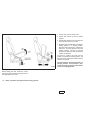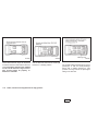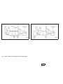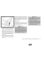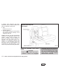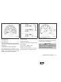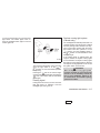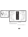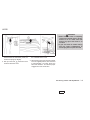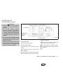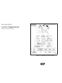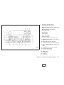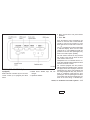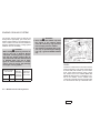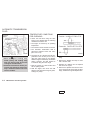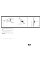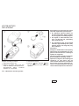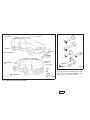
1
The inside pages of this manual contain
a minimum of 50% recycled fibers,
including 10% post-consumer fibers.
Foreword
Welcome to the growing family of new
NISSAN owners. This vehicle is delivered
to you with confidence. It was produced
using the latest techniques and strict quality
control.
This manual was prepared to help you
understand the operation and maintenance
of your vehicle so that you may enjoy many
miles of driving pleasure. Please read
through this manual before operating your
vehicle.
A separate Warranty Information Booklet
explains details about the warranties
covering your vehicle. The “NISSAN Service and Maintenance Guide” explains
details about maintaining and servicing
your vehicle. Additionally, a separate
Customer Care/Lemon Law Booklet (U.S.
only) will explain how to resolve any
concerns you may have with your vehicle, as well as clarify your rights under
your state’s lemon law.
Your NISSAN dealership knows your vehicle best. When you require any service or
have any questions, they will be glad to
assist you with the extensive resources
available to them.
READ FIRST — THEN DRIVE SAFELY
Before driving your vehicle read this owner’s manual carefully. This will ensure familiarity with controls and maintenance requirements, assisting you in the safe
operation of your vehicle.
WARNING
IMPORTANT SAFETY INFORMATION
REMINDERS FOR SAFETY!
Follow these important driving rules to
help ensure a safe and comfortable trip
for you and your passengers!
● NEVER drive under the influence of
alcohol or drugs.
● ALWAYS observe posted speed limits and never drive too fast for conditions.
● ALWAYS use your seat belts and
appropriate child restraint systems.
Pre-teen children should be seated
in the rear seat.
● ALWAYS provide information about
the proper use of vehicle safety features to all occupants of the vehicle.
● ALWAYS review this owner’s manual
for important safety information.
MODIFICATION OF YOUR VEHICLE
This vehicle should not be modified.
Modification could affect its performance, safety or durability, and may
even violate governmental regulations.
In addition, damage or performance
problems resulting from modifications
may not be covered under NISSAN
warranties.
WHEN READING THE MANUAL
This manual includes information for all
options available on this model. Therefore,
you may find some information that does
not apply to your vehicle.
All information, specifications and illustrations in this manual are those in effect at the
time of printing. NISSAN reserves the right
to change specifications or design without
notice and without obligation.
ZX
IMPORTANT INFORMATION
ABOUT THIS MANUAL
The inside pages of this manual contain
a minimum of 50% recycled fibers,
including 10% post-consumer fibers.
You will see various symbols in this manual.
They are used in the following ways:
CALIFORNIA PROPOSITION 65
WARNING
WARNING
Engine Exhaust, some of its constituents, and certain vehicle components
contain or emit chemicals known to
State of California to cause cancer and
birth defects or other reproductive
harm.
WARNING
This is used to indicate the presence of
a hazard that could cause death or
serious personal injury. To avoid or
reduce the risk, the procedures must
be followed precisely.
CAUTION
This is used to indicate the presence of
a hazard that could cause minor or
moderate personal injury or damage to
your vehicle. To avoid or reduce the
risk, the procedures must be followed
carefully.
APD1005
If you see this symbol, it means ‘‘Do not do
this’’ or ‘‘Do not let this happen.’’
© 2001 NISSAN NORTH AMERICA, INC.
GARDENA, CALIFORNIA
All rights reserved. No part of this Owner’s
Manual may be reproduced or stored in a
retrieval system, or transmitted in any form, or
by any means, electronic, mechanical, photocopying, recording or otherwise, without the
prior written permission of Nissan North
America, Inc., Gardena, California
ZX
Welcome To The World Of NISSAN
NISSAN pioneered the use of electronics and
computers in automobiles, and has led the industry in improving both performance and fuel efficiency through new engine designs and the use
of synthetic materials to reduce vehicle weight.
The company has also developed ways to build
quality into its vehicles at each stage of the
production process, both through extensive use
of automation and — most importantly —
through an awareness that people are the central element in quality control.
WFW0002
Your new NISSAN is the result of our dedication
to produce the finest in safe, reliable and economical transportation. Your vehicle is the product of a successful worldwide company that
manufactures cars and trucks in over 17 countries and distributes them in 170 nations.
NISSAN vehicles are designed and manufactured
by Nissan Motor Co., Ltd. which was founded in
Tokyo, Japan in 1933, and NISSAN affiliates worldwide, collectively growing to become the fifth largest
automaker in the world. In addition to cars and
trucks, NISSAN also makes forklift trucks, marine
engines, boats and other diversified products.
NISSAN has made a substantial and growing
investment in North America. NISSAN’s commitment is nearly $4 billion dollars in capital investments in facilities across the continent. Some of
the facilities include the Nissan Manufacturing
facility in Smyrna, Tennessee, vehicle styling
design at Nissan Design America, Inc. in San
Diego, California, and engineering at Nissan
Technical Center North America in Farmington
Hills, Michigan. Additionally, NISSAN employs
nearly 18,000 people throughout the United
States, Canada, and Mexico. An additional
71,000 people work for the 1,500 NISSAN and
INFINITI dealers across North America.
NISSAN is also a substantial contributor to the
Canadian economy. Nissan Canada Inc., its suppliers and over 140 dealers employ approximately 4,500 people. These include company
employees and the staffs of NISSAN dealers all
across Canada. In addition, many Canadians
work for companies that supply NISSAN and
NISSAN dealers with materials and services
ranging from the operation of port facilities and
transportation services, to the supply of lubricants, parts and accessories.
From the time the parts arrived from our suppliers until you took delivery of your new NISSAN,
dozens of checks were made to ensure that only
the best job was being done in producing and
delivering your vehicle. NISSAN also takes great
care to ensure that when you take your NISSAN
to your dealer for maintenance, the service technician will perform his work according to the quality
standards that have been established by the
factory.
Safety has also been built into your NISSAN. As
you know, seat belts are an integral part of the
safety systems that will help protect you and your
passengers in the event of a sudden stop or an
accident. We urge you to use the seat belts every
time you drive the vehicle.
The NISSAN story of growth and achievement
reflects our major goal: to provide you, our
customer, with a vehicle that is built with quality
and craftsmanship — a product that we can be
proud to build and you can be proud to own.
ZX
NISSAN CUSTOMER CARE PROGRAM
NISSAN CARES ...
Both NISSAN and your NISSAN dealer are dedicated to serving all your automotive needs. Your satisfaction with your vehicle and your
NISSAN dealer are our primary concerns. Your NISSAN dealer is always available to assist you with all your automobile sales and service
needs.
However, if there is something that your
NISSAN dealer cannot assist you with or
you would like to provide NISSAN directly
with comments or questions, please contact our (NISSAN’s) Consumer Affairs Department using our toll-free number:
For U.S. mainland and Alaska
customers
1-800-NISSAN-1
(1-800-647-7261)
For Hawaii customers
(808) 836-0888 (Oahu Number)
For CANADIAN customers
1-800-387-0122
The Consumer Affairs Department will ask
for the following information:
— Your name, address, and telephone
number
— Vehicle identification number (Attached
to the top of the instrument panel on the
driver’s side.)
— Date of purchase
— Current odometer reading
— Your NISSAN dealer’s name
— Your comments or questions
OR
you may write to NISSAN with the information
on the left at:
For U.S. mainland and Alaska customers
Nissan North America Inc.
Consumer Affairs Department
P.O. Box 191
Gardena, California 90248-0191
For Hawaii customers
Nissan Motor Corporation in Hawaii
2880 Kilihau St.
Honolulu, Hawaii 96819
For Canadian customers
Nissan Canada Inc.
5290 Orbitor Drive
Mississauga, Ontario L4W 4Z5
We appreciate your interest in NISSAN and thank you for buying a quality NISSAN vehicle.
ZX
ZX
Table of
Contents
Seats, restraints and supplemental air bag systems
1
Instruments and controls
2
Pre-driving checks and adjustments
3
Heater, air conditioner and audio systems
4
Starting and driving
5
In case of emergency
6
Appearance and care
7
Maintenance and do-it-yourself
8
Technical and consumer information
9
Index
10
1 Seats, restraints and supplemental air
bag systems
Seats ......................................................................1-2
Front manual seat adjustment...........................1-3
Front power seat adjustment
(if so equipped)..................................................1-4
Three-passenger seat adjustment ....................1-7
Head restraint adjustment ...............................1-10
Armrests ..........................................................1-11
Underseat storage tray....................................1-11
Flexible seating................................................1-12
Tabletop seats .................................................1-18
Seats/floor mats ...................................................1-19
Seating arrangements .....................................1-19
Seat positions ..................................................1-20
Floor mat positions ..........................................1-27
Supplemental restraint system.............................1-31
Precautions on supplemental restraint
system .............................................................1-31
Supplemental air bag warning labels ..............1-37
Supplemental air bag warning light.................1-37
Seat belts .............................................................1-39
Precautions on seat belt usage ......................1-39
Child safety......................................................1-41
Pregnant women .............................................1-42
Injured persons................................................1-42
Three-point type seat belt with retractor .........1-42
Three-point type seat belt with retractor
for second row bucket seats ...........................1-45
Three-passenger bench seat in the
second row position.........................................1-49
Three-passenger bench seat ..........................1-50
Two-point type seat belt without
retractor (center of rear seat) ..........................1-51
Seat belt extenders .........................................1-53
Seat belt maintenance ....................................1-54
Child restraints .....................................................1-54
Precautions on child restraints ........................1-54
Installation on three-passenger bench
seat center position .........................................1-56
Installation on second and third row
outboard positions ...........................................1-59
Installation on front passenger seat ................1-64
LATCH (Lower Anchors and Tether for
Children) system ..................................................1-67
Child restraint with top tether strap......................1-68
ZX
Installation on second row bench or
bucket seat ......................................................1-69
Installation on three-passenger bench
seat in second row ..........................................1-72
Installation on three-passenger bench
seat in third row...............................................1-72
Integrated child safety seats
(if so equipped)................................................1-73
ZX
SEATS
ARS1131
WARNING
● Do not ride in a moving vehicle when
the seatback is reclined. This can be
dangerous. The shoulder belt will
not be against your body. In an accident you could be thrown into it and
receive neck or other serious injuries. You could also slide under the
lap belt and receive serious internal
injuries.
● For most effective protection when
the vehicle is in motion, the seat
should be upright. Always sit well
back in the seat and adjust the seat
properly. See ‘‘Precautions on Seat
Belt Usage’’ later in this section.
1-2 Seats, restraints and supplemental air bag systems
ZX
FRONT MANUAL SEAT
ADJUSTMENT
WARNING
● Do not adjust the driver’s seat while
driving so full attention may be given
to vehicle operation. The seat may
move suddenly and could cause
loss of control of the vehicle.
● After adjustment, gently rock in the
seat to make sure it is securely
locked.
ARS1211
Forward and backward
Reclining
Rotate the lever up while you slide the seat
forward or backward to the desired position.
Release the lever to lock the seat in position.
To recline the seatback, pull the lever up and
lean back. To bring the seatback forward
again, pull the lever up and move your body
forward. The seatback moves forward. Release the lever to lock the seatback in position.
Seats, restraints and supplemental air bag systems 1-3
ZX
FRONT POWER SEAT
ADJUSTMENT (if so equipped)
● Do not operate the power support seat
for a long period of time when the engine
is off. This discharges the battery.
WARNING
● Do not adjust the driver’s seat while
driving so full attention may be given
to vehicle operation.
● Do not leave children unattended inside the vehicle. They could unknowingly activate switches or controls.
Unattended children could become
involved in serious accidents.
For memory seat and mirror information
see ‘‘Memory driver seat and mirrors’’ in the
‘‘Pre-driving checks and adjustments’’ section.
Operating tips
● The motor has an auto-reset overload
protection circuit. If the motor stops during operation, wait 30 seconds, then reactivate the switch.
1-4 Seats, restraints and supplemental air bag systems
ZX
ARS1120
ARS1212
Forward and backward
Reclining
To move the seat forward, push the power
slide switch forward. To move the seat
backward, push the power slide switch
backward. Release the switch to stop the
movement of the seat.
To recline the seat back, push the power
recliner switch backward. To return to a
more upright position, push the power recliner switch forward. Release the switch to
stop the movement of the seatback.
Seats, restraints and supplemental air bag systems 1-5
ZX
ARS1158
Seat lifter (driver’s seat only)
To raise the height of the seat, lift the power
seat height switch and release it when the
desired position is reached. To lower the
height of the seat, push the power seat
height switch down and release it when the
desired position is reached.
ARS1121
Lumbar support (if so equipped for
driver’s seat)
The lumbar support provides lower back
support to the driver. Move the lever up or
down to adjust the seat lumbar area.
1-6 Seats, restraints and supplemental air bag systems
ZX
THREE-PASSENGER SEAT
ADJUSTMENT
Reclining
To recline the three-passenger seat, lift up
on the lever and lean back until the desired
position is reached. To bring the seatback
forward, pull the lever up and lean your
body forward.
APD0852
● For most effective protection when
the vehicle is in motion, the seat
should be upright. Always sit well
back in the seat and adjust the seat
belt properly. See ‘‘Precautions on
seat belt usage’’ later in this section.
● After adjustment, gently rock in the
seat to make sure it is securely
locked.
WARNING
● Do not recline the seatback while the
vehicle is moving.
● Do not ride in a moving vehicle when
the seatback is reclined. This can be
dangerous. The shoulder belt will
not be against your body. In an accident you could be thrown into it and
receive neck or other serious injuries. You could also slide under the
lap belt and receive serious internal
injuries.
Seats, restraints and supplemental air bag systems 1-7
ZX
1. Lift the seat cushion release lever.
2. Lift the seat cushion up into the locked
position.
3. Lift the slide release lever and grasp the
bar under the seat in the center.
4. Slide the seat until locked at a passenger
seating position or a storage position.
After the seat starts moving, release the
slide lever. The seat latches at the next
latching position. Continue to lift and
release the slide lever until the desired
position is obtained.
To lower the cushion, the seat must be
locked at a passenger seating position. Lift
the seat cushion release lever and lower the
cushion until locked.
APD0853
The seat cushion cannot be lowered in a
storage position. This prevents a passenger from using a seat or seat belt that
is out of a seating position.
Sliding
Before sliding the seat, fasten the center
belt tongue to the center buckle and remove
the appropriate floor mats.
1-8 Seats, restraints and supplemental air bag systems
ZX
●
●
ARS1196
The seating system allows great flexibility.
Proper usage is important to your safety.
WARNING
● Do not slide the seat while the vehicle is moving.
●
● After adjustment, gently rock in the
seat to make sure it is securely
locked.
● After sliding the seat, check that both
sides of the seat are locked securely
by attempting to move each side of
the seat forward and backward. This
must be done before the vehicle is
●
put into motion in order to prevent
unintended movement of the seat and
passenger injuries.
Do not allow passengers to use
seats placed in storage positions for
the seat belts will not protect the
occupants. Be sure to use the proper
seat belts for each seat location.
Improper seat belt usage will increase the risk of severe injury in an
accident.
When the vehicle is being used to
carry cargo, properly secure all cargo
to help prevent it from sliding or shifting. Do not place cargo higher than
the seatbacks. In a sudden stop or
collision, unsecured cargo could
cause personal injury.
Be careful not to damage the seat
belt. Never allow anyone to ride in the
cargo area or on a seat that is in a
storage position. It is not designed
for passengers. They could be injured in sudden braking or a collision.
To prevent luggage or packages
from sliding forward during braking,
●
●
●
●
●
do not stack anything in the cargo
area higher than the seatbacks.
It is extremely dangerous to ride in a
cargo area inside of a vehicle. In a
collision, people riding in these areas are more likely to be seriously
injured or killed.
Do not allow people to ride in any
area of your vehicle that is not
equipped with seats and seat belts.
Be sure everyone in your vehicle is
in a seat and using a seat belt properly.
Be sure to replace and reposition
floor mats as discussed in ‘‘Floor
mat positioning’’ in this section.
The three-passenger sliding bench
seat is not intended to be removed
from the vehicle by consumers.
However, if it must be removed, have
a qualified person remove it. That
person should refer to the instructions in the service manual. When
seat is reinstalled, the attaching
bolts must be tightened to the appropriate torque specifications. Failure
Seats, restraints and supplemental air bag systems 1-9
ZX
to follow these instructions could
increase the chance and/or severity
of injury in an accident.
Cleaning the seat tracks
The seat tracks for the three-passenger
sliding bench seat should be cleaned periodically with a high-powered vacuum
cleaner. Dirty seat tracks may reduce the
sliding ability of the seat. A wet cleansing
agent may be used if necessary, but the
seat tracks must be thoroughly dried.
Use a cloth wrapped around a screwdriver
(or similar object) to clean the seat tracks.
Do not use your fingers to clean debris from
the tracks.
Do not apply any type of lubricant to the
seat tracks.
CAUTION
Never insert fingers into the seat track
rails. The rails may be sharp and could
cause injury.
PD1176M
HEAD RESTRAINT ADJUSTMENT
To raise the head restraint, pull it up. To
lower, push and hold the release button and
push the head restraint down.
The head restraints on the two-passenger
bench seat equipped with the integrated
child safety seats are not adjustable or
removable.
WRS0096
Adjust the head restraints so the center is
level with the center of your ears.
WARNING
Head restraints should be adjusted
properly as they may provide significant protection against injury in an accident. Do not remove them. Check the
adjustment after someone else uses
the seat.
Some seat arrangements may require removal of the head restraints when the seat
is in a storage position and not to be used by
passengers.
1-10 Seats, restraints and supplemental air bag systems
ZX
ARS1137
WRS0049
ARMRESTS
UNDERSEAT STORAGE TRAY
To use the armrests on any seat, pull them
down to the resting position.
Some front passenger seats have an underseat storage tray. Pull the tray out to access.
Seats, restraints and supplemental air bag systems 1-11
ZX
ARS1139
FLEXIBLE SEATING
Removing the second row bench
seat
WARNING
● Do not remove or install seats while
the vehicle is moving.
● After adjustment, gently rock in the
seat to make sure it is securely locked.
● Do not ride in a moving vehicle when
the seatback is reclined. This can be
dangerous. The shoulder belt will
not be against your body. In an accident you could be thrown into it and
receive neck or other serious injuries. You could also slide under the
lap belt and receive serious internal
injuries.
● For most effective protection when
the vehicle is in motion, the seat
should be upright. Always sit well
back in the seat and adjust the seat
belt properly. See ‘‘Precautions on
seat belt usage’’ later in this section.
● When adjusting or moving any of the
seats in your vehicle, do not use any
of the seat belt buckles, tongues, or
webbing to carry or move the seats.
Lifting the seats by any of the seat
belts could damage them. Damaged
seat belts should be replaced at an
authorized NISSAN dealer. Failure to
follow these instructions could increase the chance and/or severity of
injury in an accident.
1-12 Seats, restraints and supplemental air bag systems
ZX
CAUTION
● The seats are heavy. Two people
should remove or install them.
● Do not sit in seats that have been
removed from the vehicle. They may
tip over and you could be injured.
1. Detach the single window seat belt
tongue from the auxiliary buckle mounted
to the side of the seat and store the
tongue out of the way. For detailed information, see ‘‘Two buckle seat belt system for the second row bench seat’’ later
in this section.
2. Lift up the recliner lever.
3. Fold the seatback fully forward.
4. Unlock the seat legs at the two rear floor
latch levers by pulling up on the two
straps.
ARS1140
Installing the second row bench
seat
Clean the area around the seat leg floor
anchors before installing the seat.
5. Lift the back of the seat.
1. With the seatback fully folded, place the
seat behind the floor anchors and catch
the seat leg hooks into each floor anchor.
6. Slide the seat rearward off the front anchor positions.
2. Push down on the back of the seat to
secure the two rear floor latches.
all four seat legs are securely latched.
5. Insert the single window seat belt tongue
into the auxiliary buckle mounted to the
side of the seat.
3. Lift up the recliner lever and raise the
seatback.
4. Rock the seat back and forth to be sure
Seats, restraints and supplemental air bag systems 1-13
ZX
Removing second row bucket seats
●
●
●
●
WARNING
Do not remove or install seats while
the vehicle is moving.
After adjustment, gently rock in the
seat to make sure it is securely
locked.
Do not ride in a moving vehicle when
the seatback is reclined. This can be
dangerous. The shoulder belt will
not be against your body. In an accident you could be thrown into it and
receive neck or other serious injuries. You could also slide under the
lap belt and receive serious internal
injuries.
For most effective protection when
the vehicle is in motion, the seat
should be upright. Always sit well
back in the seat and adjust the seat
belt properly. See ‘‘Precautions on
seat belt usage’’ later in this section.
● When adjusting or moving any of the
seats in your vehicle, do not use any
of the seat belt buckles, tongues, or
webbing to carry or move the seats.
Lifting the seats by any of the seat
belts could damage them. Damaged
seat belts should be replaced at your
NISSAN dealer. Failure to follow
these instructions could increase the
chance and/or severity of injury in an
accident.
CAUTION
● The seats are heavy. Two people
should remove or install them.
● Do not sit in seats that have been
removed from the vehicle. They may
tip over and you could be injured.
1-14 Seats, restraints and supplemental air bag systems
ZX
ARS1141
1. Lift the recliner lever.
2. Fold the seatback fully forward.
Seats, restraints and supplemental air bag systems 1-15
ZX
ARS1143
3. Unlock the seat legs at the two rear floor
latch levers by pulling up on the two
straps.
4. Lift the back of the seat and slide it
rearward off the front anchor positions.
1-16 Seats, restraints and supplemental air bag systems
ZX
Installing the second row bucket
seats
Clean the area around the seat leg floor
anchors before installing the seat.
1. With the seatback fully folded, place the
seat behind the floor anchors and slide
seat leg hooks so they catch into each
floor anchor.
ARS1142
ARS1144
4. Rock the seat back and forth to be sure it
is securely latched.
Second row passenger side bucket
seat
The second row bucket seats are not
interchangeable. If you are having difficulty installing the seats, you may have
them in the wrong location.
The bucket seat near the passenger side
sliding door can be moved forward to allow
easier entry and exit for third seat passengers.
2. Push down on the rear of the seat to
secure the two rear floor latches.
3. Lift the recliner lever and raise the seatback.
Seats, restraints and supplemental air bag systems 1-17
ZX
WARNING
● Never place hard items such as coffee mugs or drinking glasses on the
tabletop seats when the vehicle is
moving. Any item can become a projectile inside a vehicle involved in a
collision. To help prevent personal
injury, never leave loose items on
the folded-down tabletop seats when
the vehicle is moving.
● Do not use the tabletop and cup
holder feature while the vehicle is in
motion unless you are properly
seated with your seat belt on.
ARS1138
TABLETOP SEATS
The second and third row seats convert into
tabletops with built-in cupholders. To use
the tabletop seats, lift up on the seatback
release lever and fold the seatback forward.
1-18 Seats, restraints and supplemental air bag systems
ZX
SEATS/FLOOR MATS
SEATING ARRANGEMENTS
Many different arrangements for passenger
seating or cargo hauling are available, as
you will see in the following illustrations. The
second row seats may be removed and the
third row seat may be moved forward to the
second row seating position. The second
and third row seats have a fold-down tabletop feature. This offers a variety of uses for
the vehicle when moving or stopped.
The illustrations shown reflect the different
seating positions available.
LRS0050
There is also a lever behind the passenger
bucket seat that allows third seat passengers to move the bucket seat forward without help from another passenger.
Before you begin to arrange the seats in
your vehicle, read all of the cautions and
warnings in this section, including the
information on the removable floor mats.
Also observe any labels that are in the
vehicle.
Seats, restraints and supplemental air bag systems 1-19
ZX
WARNING
● While the vehicle is in motion, passengers should always be seated in
a forward facing direction in a seat
which is properly secured and adjusted. Seat belts should always be
used. Sitting without a seat belt in a
seat that is not properly secured in
one of the locations shown in this
chapter, or in a place without a seat
and seat belt can result in personal
injury in a sudden stop or collision.
● Do not ride in a moving vehicle when
the seatback is reclined. This can be
dangerous. The shoulder belt will
not be against your body. In an accident, you could be thrown into it and
receive neck or other serious injuries. You could also slide under the
lap belt and receive serious internal
injuries.
● For the most effective protection
when the vehicle is in motion, the
seat should be upright. Always sit
well back in the seat and adjust the
seat belt properly.
● It is extremely dangerous to ride in a
cargo area inside of a vehicle. In a
collision, people riding in these areas are more likely to be seriously
injured or killed.
● Do not allow people to ride in any
area of your vehicle that is not
equipped with seats and seat belts.
● Be sure everyone in your vehicle is
in a seat and using a seat belt properly.
● Do not place hard items such as
coffee mugs or drinking glasses on
the tabletop seats when the vehicle
is moving. Any item can become a
projectile inside a vehicle involved in
a collision. To help prevent personal
injury, never leave loose items on
the fold-down tabletop seats when
the vehicle is moving.
APD0096
SEAT POSITIONS
With second row bench seat
The most common seating arrangement for
seven passengers is with the threepassenger bench seat in seating position
#1. This provides more leg room for the
passengers sitting in the third row.
1-20 Seats, restraints and supplemental air bag systems
ZX
ARS1204
When more cargo area room is necessary,
the three-passenger sliding bench seat can
be moved to seating position #2 or #3.
These seating arrangements provide less
leg room for third row passengers, but more
cargo room.
APD0042
The fold-down tabletop seats in the second
and third rows provide a surface for eating
or playing games on long trips.
Seats, restraints and supplemental air bag systems 1-21
ZX
APD0043
APD0049
APD0044
If a considerable amount of cargo area is
needed, the seat cushion of the threepassenger sliding bench seat can be flipped
up and the seat can be moved up to storage
position #2, just behind the second row
seat.
When maximum cargo area is needed and
there are no rear seat passengers, the
second row seat can be removed and the
three-passenger sliding bench seat can be
moved up to storage position #1, just behind
the front seats.
The second row bench seat can be folded
down to serve as a tabletop for passengers
sitting in the three-passenger bench seat.
1-22 Seats, restraints and supplemental air bag systems
ZX
APD0045
APD0046
APD0047
The second and third row bench seats can
be folded down to tabletops.
To increase cargo area space, the second
row bench seat can be removed and the
three-passenger sliding seat can be moved
up to the second row position.
The third seat can be folded down into a
tabletop.
Seats, restraints and supplemental air bag systems 1-23
ZX
APD0048
APD0050
With the third seat folded down and the
second seat removed, cargo can be placed
in between the front seats and the third row
seat. Passengers should not be allowed
to ride in areas meant for cargo. Passengers should always be properly restrained in seat belts.
The second row seat can be folded down
and the third row seat can be moved just
behind it in a storage position.
APD0128
With second row bucket seats
The normal seating arrangement for seven
passengers is with the three-passenger
bench seat in seating position #1. This
provides more leg room for the passengers
sitting in the third row.
1-24 Seats, restraints and supplemental air bag systems
ZX
ARS1195
When one passenger in the threepassenger bench seat would like more leg
room, one of the second row bucket seats
can be removed.
Seats, restraints and supplemental air bag systems 1-25
ZX
ARS1205
When more cargo area room is necessary,
the three-passenger sliding bench seat can
be moved to seating position #2 or #3. This
seating arrangement provides less leg room
for third row passengers, but more cargo
room.
APD0053
If passengers in the three-passenger bench
seat would like more leg room, both second
row bucket seats can be removed. Passengers should not be allowed to ride in
areas meant for cargo. Passengers
should always be properly restrained by
seat belts.
1-26 Seats, restraints and supplemental air bag systems
ZX
ARS1216
FLOOR MAT POSITIONS
Seven passenger seating
Removable floor mats
Whenever you remove the mats for any reason, the mats must be
reinstalled before passengers ride in your vehicle. The floor mats
are specifically designed to keep objects out of the seat tracks. The
cargo mat is reversible.
ARS1217
Three-passenger bench seat in storage position
CAUTION
It is important to replace the floor mats whenever they are
removed for any reason. The floor mats are intended to help
prevent the possibility that high heeled shoes or similar
objects might become stuck in the seat tracks. Failure to
replace the floor mats might result in personal injury.
Be sure to keep the seat tracks clear of debris by cleaning them
periodically.
Review the following illustrations so you will know the proper way to
place the floor mats with the various seating arrangements available
in your vehicle.
Seats, restraints and supplemental air bag systems 1-27
ZX
ARS1218
ARS1219
Five Passenger Seating
1-28 Seats, restraints and supplemental air bag systems
ZX
ARS1220
ARS1221
Five Passenger Seating with cargo room
Three-passenger bench seat in fully forward position
The step mats are not used in this seating configuration.
The step mats are not used in this seating configuration.
Seats, restraints and supplemental air bag systems 1-29
ZX
over the floor mat positioning bracket located at the base of the driver’s seat.
Push the positioning pins into the seat
tracks to ensure correct installation, then
straighten the mats as necessary.
The step mats have holes in addition to
pins. When the mats are arranged properly,
the positioning pins of the two mats on
either side of each step mat should fit
through the holes in the step mats and into
the seat track.
APD0083
Floor mat positioning aid
Positioning pins are attached to three of the
floor mats. The cargo mat and front mats do
not have pins. However, the driver’s front
floor mat has a grommet which is placed
WARNING
● Do not allow passengers to use
seats placed in storage positions
because the seat belts will not protect the occupants. Be sure to use
the proper seat belts for each seat
location. Improper seat belt usage
will increase the risk of severe injury
in an accident.
● It is extremely dangerous to ride in a
cargo area inside of a vehicle. In a
collision, people riding in these areas are more likely to be seriously
injured or killed.
● Properly secure all cargo to help
prevent it from sliding or shifting. Do
not place cargo higher than the seatbacks. In a sudden stop or collision,
unsecured cargo could cause personal injury.
● Do not allow people to ride in any
area of the vehicle that is not
equipped with seats and seat belts.
● Be sure everyone in your vehicle is
in a seat and is using a seat belt
properly.
● Failure to follow proper seating instructions in this section could result in serious personal injury in an
accident or during a sudden stop.
1-30 Seats, restraints and supplemental air bag systems
ZX
SUPPLEMENTAL RESTRAINT
SYSTEM
PRECAUTIONS ON SUPPLEMENTAL RESTRAINT SYSTEM
This supplemental restraint system description contains important information concerning the driver and passenger supplemental
front air bags. The supplemental restraint
system air bags can help reduce impact
force to the driver and front passenger in
certain frontal collisions. The supplemental
air bags are designed to supplement the
crash protection provided by the seat belts
and are not a substitute for the seat belts.
The seat belts should always be correctly
worn and the driver and front passenger
seated a suitable distance from the steering
wheel and instrument panel. See ‘‘Seat
belts’’ and “Precautions on seat belt usage”
later in this section for details.
The supplemental air bags operate only
when the ignition switch is in the ON or
START position.
After turning the ignition key to the ON
position, the supplemental air bag warning light illuminates. The supplemental
air bag warning light will turn off after
about 7 seconds if the system is operational.
ARS1132
WARNING
● The supplemental front air bag ordinarily will not inflate in the event of a
side impact, rear impact, roll over, or
lower severity frontal collision. Always
wear your seat belts to help reduce the
risk or severity of injury in various
kinds of accidents.
● The seat belts and the supplemental
front air bag are most effective when
you are sitting back and upright in the
seat. Front air bags inflate with great
force. If you are unrestrained, leaningforward, sitting sideways, you are at
greater risk of injury or death in a
crash. You may also receive serious or
fatal injuries from the supplemental
front air bag if you are up against it
when it inflates. Always sit back
against the seatback and as far away as
practical from the steering wheel or
instrument panel. Always use the seat
belts.
● Keep hands on the outside of the steering wheel. Placing them inside the
steering wheel rim could increase the
risk that they are injured when the
supplemental front air bag inflates.
Seats, restraints and supplemental air bag systems 1-31
ZX
ARS1133
ARS1041
ARS1042
1-32 Seats, restraints and supplemental air bag systems
ZX
ARS1043
ARS1045
ARS1044
ARS1046
WARNING
● Never let children ride unrestrained.
Do not attempt to hold them in your
lap or arms. Some examples of dangerous riding positions are shown in
the illustrations.
● Children may be severly injured or
killed when the supplemental front
air bag inflates if they are not properly restrained.
● Never install a rear-facing child restraint in the front seat. An inflating
supplemental front air bag could seriously injure or kill your child. See
‘‘Child restraints’’ later in this section for details.
Seats, restraints and supplemental air bag systems 1-33
ZX
ally inhale it, as it may cause irritation and
choking. Those with a history of a breathing
condition should get fresh air promptly.
The supplemental front air bags, along with
the use of seat belts, help to cushion the
impact force on the face and chest of the
occupant. They can help save lives and
reduce serious injuries. However, an inflating front air bag may cause facial abrasions
or other injuries. Front air bags do not
provide restraint to the lower body.
WRS0075
Supplemental front air bag system
The driver supplemental air bag is located in
the center of the steering wheel. The front
passenger supplemental air bag is mounted in
the dashboard above the glove box.
These systems are designed to meet optional
certification requirements under U.S. regulations. They are also permitted in Canada. The
optional certification allows front air bags to
be designed to inflate somewhat less forcefully than previously. However, all of the
information, cautions and warnings in this
manual still apply and must be followed.
The supplemental front air bag system is
designed to inflate in higher severity frontal
collisions, although it may inflate if the forces
in another type of collision are similar to those
of a higher severity frontal impact. It may not
inflate in certain frontal collisions. Vehicle
damage (or lack of it) is not always an indication of proper supplemental air bag system
operation.
When the supplemental front air bag inflates, a fairly loud noise may be heard,
followed by the release of smoke. This
smoke is not harmful and does not indicate
a fire. Care should be taken to not intention-
Seat belts should be correctly worn and the
driver and passenger seated upright as far
away as practical from the steering wheel or
instrument panel. The supplemental front air
bag inflates quickly in order to help protect
the front occupants. Because of this, the
force of the front air bag inflating can increase the risk of injury if the occupant is too
close to, or is against, the air bag module
during inflation.The air bag deflates quickly
after a collision.
The supplemental air bags operate only
when the ignition switch is in the ON or
START position.
After turning the ignition key to the ON
position, the supplemental air bag warn-
1-34 Seats, restraints and supplemental air bag systems
ZX
ing light illuminates. The supplemental
air bag warning light will turn off after
about 7 seconds if the system is operational.
●
●
●
●
WARNING
Do not place any objects on the
steering wheel pad or on the instrument panel. Also, do not place any
objects between any occupant and
the steering wheel or instrument
panel. Such objects may become
dangerous projectiles and cause injury if the supplemental front air bag
inflates.
Right after inflation, several air bag
system components will be hot. Do
not touch them; you may severely
burn yourself.
No unauthorized changes should be
made to any components or wiring
of the supplemental front air bag
system. This is to prevent accidental
inflation of the air bag or damage to
the air bag system.
Do not make unauthorized changes
to your vehicle’s electrical system,
suspension system or front end
structure. This could affect proper
operation of the supplemental front
air bag system.
● Tampering with the supplemental
front air bag system may result in
serious personal injury. Tampering
includes changes to the steering
wheel and the instrument panel assembly by placing material over the
steering wheel pad and above the
instrument panel or by installing additional trim material around the air
bag system.
● Work around and on the supplemental front air bag system should be
done by an authorized NISSAN
dealer. Installation of electrical
equipment should also be done by
an authorized NISSAN dealer. The
Supplemental Restraint System
(SRS) wiring should not be modified
or disconnected. Unauthorized electrical test equipment and probing
devices should not be used on the
air bag system.
● A cracked windshield should be replaced immediately by a qualified
repair facility. A cracked windshield
could affect inflation of the supplemental air bag system.
Seats, restraints and supplemental air bag systems 1-35
ZX
● The SRS wiring harness connectors
are yellow for easy identification.
When selling your vehicle, we request that
you inform the buyer about the supplemental air bag system and guide the buyer to the
appropriate sections in this owner’s manual.
Pre-tensioner seat belt system (For
front seats)
WARNING
● The pre-tensioner seat belt cannot
be reused after activation. It must be
replaced together with the retractor
as a unit.
● If the vehicle becomes involved in a
frontal collision but the pretensioner is not activated, be sure to
have the pre-tensioner system
checked and, if necessary, replaced
by your NISSAN dealer.
● No unauthorized changes should be
made to any components or wiring
of the pre-tensioner seat belt system. This is to prevent accidental
activation of the pre-tensioner seat
belt or damage to the pre-tensioner
seat belt operation. Tampering with
the pre-tensioner seat belt system
may result in serious personal injury.
● Work around and on the pretensioner system should be done by
an authorized NISSAN dealer. Installation of electrical equipment should
also be done by an authorized
NISSAN dealer. Unauthorized electrical test equipment and probing devices should not be used on the
pre-tensioner seat belt system.
● If you need to dispose of the pretensioner or scrap the vehicle, contact an authorized NISSAN dealer.
Correct pre-tensioner disposal procedures are set forth in the appropriate NISSAN Service Manual. Incorrect disposal procedures could
cause personal injury.
The front seat pre-tensioner seat belt system activates in conjunction with the supplemental front air bag. Working with the seat
belt retractor, it helps tighten the seat belt
the instant the vehicle becomes involved in
certain types of collisions, thereby restraining seat occupants.
The pre-tensioner is encased with the seat
belt’s retractor. These seat belts are used
the same as conventional seat belts.
When the pre-tensioner seat belt activates,
smoke is released and a loud noise may be
heard. The smoke is not harmful and does
not indicate a fire. Care should be taken to
not intentionally inhale it, as it may cause
irritation and choking. Those with a history
of a breathing condition should get fresh air
promptly.
If any abnormality occurs in the pretensioner system, the air bag warning light
will flash intermittently after the ignition key is turned to the ON or START
position. In this case, the pre-tensioner seat
belt will not function properly.
When selling your vehicle, we request that
you inform the buyer about the pretensioner seat belt system and guide the
buyer to the appropriate sections in this
owner’s manual.
1-36 Seats, restraints and supplemental air bag systems
ZX
ARS1123
WRS0090
SUPPLEMENTAL AIR BAG
WARNING LABELS
SUPPLEMENTAL AIR BAG
WARNING LIGHT
Warning labels about the supplemental air
bag system are placed in the vehicle as
shown in the illustration.
The supplemental air bag warning light,
displaying
in the instrument panel,
monitors the circuits of the supplemental air
bag and pretensioner systems. The circuits
monitored by the air bag warning light include the diagnosis sensor unit, supplemental air bag modules, pre-tensioner seat belt
system and all related wiring.
When the ignition key is in the ON or START
position, the supplemental air bag warning
light illuminates for about 7 seconds and
Seats, restraints and supplemental air bag systems 1-37
ZX
then turns off. This means the system is
operational.
If any of the following conditions occur, the
supplemental air bag and pre-tensioner
seat belt systems need servicing and
should be taken to your nearest authorized
NISSAN dealer.
● The supplemental air bag warning light
remains on after approximately 7 seconds.
● The supplemental air bag warning light
flashes intermittently.
● The supplemental air bag warning light
does not come on at all.
Repair and replacement procedure
The supplemental front air bag modules are
designed to inflate on a one-time-only basis.
As a reminder, unless it is damaged, the
supplemental air bag light remains illuminated after inflation has occurred. Repair
and replacement of the air bag system
should be done only by an authorized NISSAN dealer.
When maintenance work is required on the
vehicle, the supplemental front air bag system and related parts should be pointed out
to the person conducting the maintenance.
The ignition key should always be in the
LOCK position when working under the
hood or inside the vehicle.
Under these conditions, the supplemental
air bag and/or pre-tensioner seat belts may
not operate properly. It must be checked
and repaired. Take your vehicle to the nearest authorized NISSAN dealer.
WARNING
● Once the supplemental front air bag
inflates, the air bag module will not
function again and should be replaced by an authorized NISSAN
dealer. The air bag module cannot be
repaired.
● The supplemental front air bag system should be inspected by an authorized NISSAN dealer if there is
any damage to the front end portion
of the vehicle or replaced if the
supplemental air bag has inflated.
● If you need to dispose of a supplemental air bag or scrap the vehicle,
contact an authorized NISSAN dealer.
Correct supplemental air bag disposal procedures are set forth in the
appropriate NISSAN Service Manual.
Incorrect disposal procedures could
cause personal injury.
WARNING
If the supplemental air bag warning
light is on, it could mean that the
supplemental front air bag system will
not operate in an accident.
1-38 Seats, restraints and supplemental air bag systems
ZX
SEAT BELTS
PRECAUTIONS ON SEAT BELT
USAGE
Your chances of being injured or killed in an
accident and/or the severity of injury may be
greatly reduced if you are wearing your seat
belt and it is properly adjusted. NISSAN
strongly encourages you and all of your
passengers to buckle up every time you
drive, even if your seating position includes
a supplemental air bag.
Most U.S. States and Canadian provinces or territories require that seat belts
be worn at all times when a vehicle is
being driven.
ARS1134
WARNING
● Every person who drives or rides in
this vehicle should use a seat belt at
all times. Children should be properly restrained and, if appropriate, in
a child restraint.
● The belt should be adjusted to a snug
fit. Failure to do so may reduce the
effectiveness of the entire restraint
system and increase the chance or
severity of injury in an accident. Serious injury or death can occur if the
seat belt is not worn properly.
● Always route the shoulder belt over
your shoulder and across your chest.
Never run the belt behind your back,
under your arm or across your neck.
The belt should be away from your
face and neck, but not falling off your
shoulder.
● Position the lap belt as low and snug
as possible AROUND THE HIPS,
NOT THE WAIST. A lap belt worn too
high could increase the risk of internal injuries in an accident.
Seats, restraints and supplemental air bag systems 1-39
ZX
ARS1047
ARS1050
ARS1049
● Be sure the seat belt tongue is securely fastened to the proper buckle.
● Do not wear the belt inside out or
twisted. Doing so may reduce its
effectiveness.
● Do not allow more than one person
to use the same seat belt.
● Never carry more people in the vehicle than there are seat belts.
● If the seat belt warning light glows
continuously while the ignition is
turned ON with all doors closed and
all seat belts fastened, it may indicate a malfunction in the system.
Have the system checked by an authorized NISSAN dealer.
belt assemblies in use during a collision be replaced unless the collision
was minor and the belts show no
damage and continue to operate
properly. Seat belt assemblies not in
use during a collision should also be
inspected and replaced if either damage or improper operation is noted.
● All seat belt assemblies, including
retractors and attaching hardware,
should be inspected after any collision by an authorized NISSAN dealer.
NISSAN recommends that all seat
1-40 Seats, restraints and supplemental air bag systems
ZX
● All child restraints and attaching
hardware should be inspected after
any collision. Always follow the restraint manufacturer’s inspection instructions and replacement recommendations. The child restraints
should be replaced if they are damaged.
CHILD SAFETY
Children need adults to help protect them.
They need to be properly restrained.
The proper restraint depends on the
child’s size. Generally, infants up to
about 1 year and less than 20 pounds (9
kg) should be placed in rear facing child
restraints. Forward facing child restraints are available for children who
outgrow rear facing child restraints.
WARNING
Infants and children need special protection. The vehicle’s seat belts may
not fit them properly. The shoulder belt
may come too close to the face or neck.
The lap belt may not fit over their small
hip bones. In an accident, an improperly fitting seat belt could cause serious or fatal injury. Always use appropriate child restraints.
All US States and Canadian provinces require the use of approved child restraints for
infants and small children. See ‘‘Child restraints’’ later in this section.
In addition, there are many types of child
restraints available for larger children which
should be used for maximum protection.
NISSAN recommends that all pre-teens
and children be restrained in the rear
seat if possible. According to accident
statistics, children are safer when properly restrained in the rear seat than in the
front seat.
This is especially important because your
vehicle has a supplemental restraint system (Air bag system) for the front passen-
ger (For precautions, see ‘‘Supplemental
restraint system’’ earlier in this section).
Infants and small children
NISSAN recommends that infants and small
children be placed in a child restraint that
complies with the Federal Motor Vehicle
Safety Standards or Canadian Motor Vehicle Safety Standards. You should choose
a child restraint that fits your vehicle and
always follow the manufacturer’s instructions for installation and use.
Larger children
Children who are too large for child restraints should be seated and restrained by
the seat belts which are provided.
If the child’s seating position has a shoulder
belt that fits close to the face or neck, the use
of a booster seat (commercially available)
may help overcome this. The booster seat
should raise the child so the shoulder belt is
properly positioned across the top, middle
portion of the shoulder and the lap belt is low
on the hips. The booster seat should fit the
vehicle seat and have a label certifying that
it complies with Federal Motor Vehicle
Safety Standards or Canadian Motor Vehicle Safety Standards. Once the child has
Seats, restraints and supplemental air bag systems 1-41
ZX
grown enough so the shoulder belt is no
longer on or near the face and neck, use the
shoulder belt without the booster seat.
WARNING
Never let a child stand or kneel on any
seat and do not allow a child in the
cargo areas while the vehicle is moving. The child could be seriously injured or killed in an accident or sudden
stop.
PREGNANT WOMEN
NISSAN recommends that pregnant women
use seat belts. The seat belt should be worn
snug, and always position the lap belt as
low as possible around the hips, not the
waist. Place the shoulder belt over your
shoulder and across your chest. Never run
the lap/shoulder belt over your abdominal
area. Contact your doctor for specific recommendations.
INJURED PERSONS
NISSAN recommends injured persons use
seat belts, depending on the injury. Check
with your doctor for specific recommendations.
ARS1159
WRS0029
THREE-POINT TYPE SEAT BELT
WITH RETRACTOR
you could be thrown into it and receive neck or other serious injuries.
You could also slide under the lap belt
and receive serious internal injuries.
● For most effective protection when
the vehicle is in motion, the seat
should be upright. Always sit well
back in the seat and adjust the seat
properly. See “Precautions on seat
belt usage” earlier in this section.
WARNING
● Every person who drives or rides in
this vehicle should use a seat belt at
all times.
● Do not ride in a moving vehicle when
the seatback is reclined. This can be
dangerous. The shoulder belt will not
be against your body. In an accident
1-42 Seats, restraints and supplemental air bag systems
ZX
‘‘Child restraints’’ later in this section for
more information.
The automatic locking mode should be
used only for child restraint installation.
During normal seat belt use by a passenger, the locking mode should not be
activated. If it is activated, it may cause
uncomfortable seat belt tension.
ARS1161
Fastening the seat belts
1. Adjust the seat.
2. Slowly pull the seat belt out of the retractor and insert the tongue into the buckle
until you hear and feel the latch engage.
The retractor is designed to lock during
a sudden stop or on impact. A slow
pulling motion permits the seat belt to
move, and allows you some freedom of
movement in the seat.
ARS1162
3. Position the lap belt portion low and
snug on the hips as shown.
4. Pull the shoulder belt portion toward the
retractor to take up extra slack.
The front seat passenger seat belt and rear
three-point seat belts have a cinching
mechanism for child restraint installation. It is
referred to as the automatic locking mode.
When the automatic locking mode is activated, the seat belt cannot be withdrawn
again until the seat belt tongue is detached
from the buckle and fully retracted. Refer to
Seats, restraints and supplemental air bag systems 1-43
ZX
belts, check their operation as follows.
● Grasp the shoulder belt and pull quickly
forward. The retractor should lock and
restrict further belt movement.
If the retractor does not lock during this
check or if you have any questions about
belt operation, see an authorized NISSAN
dealer.
ARS1054
Unfastening the seat belts
To unfasten the seat belt, press the button
on the buckle. The seat belt automatically
retracts.
Checking seat belt operation
Seat belt retractors are designed to lock
seat belt movement:
1) when the seat belt is pulled quickly from
the retractor, and
2) when the vehicle slows down rapidly.
APD0831
Shoulder belt height adjustment (for
front seats)
The shoulder belt anchor height should be
adjusted to the position best for you (See
‘‘Precautions on seat belt usage’’ earlier in
this section.). To adjust, press the release
button and move the shoulder belt anchor to
the desired position so the belt passes over
the center of the shoulder. The belt should
be away from your face and neck, but not
falling off your shoulder. Release the button
to lock the shoulder belt anchor into position.
To increase your confidence in the seat
1-44 Seats, restraints and supplemental air bag systems
ZX
WARNING
● After adjustment, release the adjustment button and try to move the
shoulder belt anchor up and down to
make sure it is securely fixed in
position.
● The shoulder belt anchor height
should be adjusted to the position
best for you. Failure to do so may
reduce the effectiveness of the entire restraint system and increase
the chance or severity of injury in an
accident.
not be against your body. In an accident you could be thrown into it and
receive neck or other serious injuries. You could also slide under the
lap belt and receive serious internal
injuries.
● For most effective protection when
the vehicle is in motion, the seat
should be upright. Always sit well
back in the seat and adjust the seat
belt properly.
ARS1083
THREE-POINT TYPE SEAT BELT
WITH RETRACTOR FOR SECOND
ROW BUCKET SEATS
WARNING
● Every person who drives or rides in
this vehicle should use a seat belt at
all times.
● Do not ride in a moving vehicle when
the seatback is reclined. This can be
dangerous. The shoulder belt will
Fastening the seat belt
1. Adjust the seat.
2. Slowly pull the seat belt out of the retractor and insert the tongue into the buckle
until you hear and feel the latch engage.
The retractor is designed to lock during
a sudden stop or on impact. A slow
pulling motion permits the seat belt to
move, and allows you some freedom of
movement in the seat.
Seats, restraints and supplemental air bag systems 1-45
ZX
Two buckle seat belt system for the
second row bench seat
There is a two buckle seat belt system for
the seating position of the second row
bench seat next to the passenger side sliding door.
APD0830
3. Position the lap belt portion low and
snug on the hips as shown.
4. Pull the shoulder belt portion toward the
retractor to take up extra slack.
WARNING
● It is very important that you follow the
instructions in this section before
anyone rides in this seating position
of the two-passenger bench seat.
● Failure to do so may result in improper positioning of seat belt which
could lead to increased likelihood or
severity of injury in a sudden stop or
collision.
ARS1127
The two-passenger bench seat in the second row has a seat belt system made up of
two buckles and two tongues. There are two
body attaching points (one upper and one
lower) that attach each end of the seat belt
webbing.
1-46 Seats, restraints and supplemental air bag systems
ZX
positioned properly and fastened to the
buckle mounted in the middle of the seat.
When the two buckle seat belt system is not
in use, the webbing can be secured with the
seat belt clip. The seat belt clip should not
be used with a child seat or during seat belt
usage. The seat belt clip opening should
face the front of the vehicle.
ARS1126
WRS0051
One of the seat belt tongues has two ‘‘windows’’ (or holes) and the other has only one
‘‘window’’. The seat belt tongue with one
window attaches to the auxiliary buckle
mounted to the side of the seat. The seat
belt tongue with two windows should be
A twisted belt may prevent the retractor
from working properly. If the two buckle seat
belt system is twisted, disengage the single
window tongue from the auxiliary buckle on
the side of the seat, remove the twist and
reinstall the tongue into the auxiliary buckle
until you hear a snap and feel the latch
engage.
Both tongues must be attached to their
appropriate buckles whenever someone
is riding in that seating position. If the
tongues are released to allow a third row
passenger to enter or exit, the tongues
must be reattached.
Seats, restraints and supplemental air bag systems 1-47
ZX
When the two-passenger bench seat is removed from the vehicle, you must detach
the single window tongue from the auxiliary
buckle.
Checking seat belt operation
(Three-point type seat belt with
retractor)
When the three-passenger bench seat is
moved up to the second row position, the
passenger seated near the passenger
side sliding door needs to use the double
window tongue and the standard buckle
only. Because the three-passenger
bench seat is wider and closer to the
passenger side sliding door, the single
window seat belt tongue and the auxiliary
buckle are not necessary.
Seat belt retractors are designed to lock
seat belt movement:
1) when the seat belt is pulled quickly from
the retractor, and
2) when the vehicle slows down rapidly.
To increase your confidence in the seat
belts, check their operation as follows.
ARS1125
CAUTION
Third row passengers must be very
careful when exiting because of the
auxiliary seat belt. It is important to
step over the seat belt guide and belt
webbing to avoid tripping.
● Grasp the shoulder belt and pull quickly
forward. The retractor should lock and
restrict further belt movement.
If the retractor does not lock during this
check or if you have any questions about
seat belt operation, see an authorized
NISSAN dealer.
Unfastening the seat belts
To unfasten the seat belt, press the button
on the buckle. The seat belt automatically
retracts.
1-48 Seats, restraints and supplemental air bag systems
ZX
THREE-PASSENGER BENCH
SEAT IN THE SECOND ROW
POSITION
Fastening the seat belts
When the three-passenger bench seat is
moved up to the second row position, the
passenger seated near the passenger
side sliding door needs to use the double
window tongue and the standard buckle
only. Because the three-passenger
bench seat is wider and closer to the
passenger side sliding door, the single
window seat belt tongue and the auxiliary
buckle are not necessary.
1. Adjust the seat.
WRS0015
WRS0052
2. Slowly pull the seat belt out of the retractor and insert the tongue into the buckle
until you hear and feel the latch engage.
3. Position the passenger side shoulder belt
in the shoulder belt retainer.
Seats, restraints and supplemental air bag systems 1-49
ZX
WRS0053
WRS0015
4. Position the lap belt portion low and
snug on the hips as shown.
THREE-PASSENGER BENCH
SEAT
5. Pull the shoulder belt portion toward the
retractor to take up extra slack.
Fastening the seat belts
1. Adjust the seat.
WARNING
● Do not ride in a moving vehicle when
the seatback is reclined. This can be
dangerous. The shoulder belt will
not be against your body. In an accident you could be thrown into it and
receive neck or other serious injuries. You could also slide under the
lap belt and receive serious internal
injuries.
● For most effective protection when
the vehicle is in motion, the seat
should be upright. Always sit well
back in the seat and adjust the seat
belt properly.
Third row passenger shoulder belts are
located slightly behind the third row
seating position. Never try to use the
seat belts for the second row passengers which are in front of the threepassenger bench seat.
1-50 Seats, restraints and supplemental air bag systems
ZX
WARNING
Use of the second row three-point seat
belts by third row passengers could
increase the chance or severity of injury in a sudden stop or an accident.
2. Slowly pull the seat belt out of the retractor and insert the tongue into the buckle
until you hear and feel the latch engage.
The retractor is designed to lock during
a sudden stop or on impact. A slow
pulling motion permits the belt to move,
and allows you some freedom of movement in the seat.
ARS1084
3. Position the lap belt portion low and
snug on the hips as shown.
4. Pull the shoulder belt portion toward the
retractor to take up extra slack.
APD0162
TWO-POINT TYPE SEAT BELT
WITHOUT RETRACTOR (Center
of rear seat)
Selecting correct set of seat belts
The seat belt tongues must be fastened into
the seat belt buckles as illustrated above.
WARNING
Any rear seat belt tongue will connect
to any seat belt buckle; therefore, it is
important to follow the illustration
above. Failure to do so could increase
Seats, restraints and supplemental air bag systems 1-51
ZX
the chance and/or severity of injury in
an accident.
ARS1055
Fastening the seat belts
1. Insert the tongue into the buckle until you
hear and feel the latch engage.
ARS1238
2. Tighten the seat belt by pulling the free
end of the belt away from the tongue.
1-52 Seats, restraints and supplemental air bag systems
ZX
ARS1076
ARS1057
3. Position the lap belt low and snug on
the hips as shown.
4. Loosen the seat belt by holding the
tongue at a right angle to the belt, then
pull on the belt.
ARS1058
Unfastening the seat belts
To unfasten the belt, press the button on the
buckle.
SEAT BELT EXTENDERS
If, because of body size or driving position,
it is not possible to properly fit the front seat
lap belts and fasten them, an extender is
available which is compatible with the installed seat belts. The extender adds approximately 8 inches (200 mm) of length
and may be used for either the driver or front
passenger seating position. See an authoSeats, restraints and supplemental air bag systems 1-53
ZX
CHILD RESTRAINTS
rized NISSAN dealer for assistance if the
extender is required.
WARNING
● Only NISSAN seat belt extenders,
made by the same company which
made the original equipment belts,
should be used with NISSAN seat
belts.
● Periodically check to see that the seat
belt and the metal components such
as buckles, tongues, retractors, flexible
wires and anchors work properly. If loose
parts, deterioration, cuts or other damage on the webbing is found, the entire
seat belt assembly should be replaced.
● Persons who can use the standard
seat belt should not use an extender.
Such unnecessary use could result
in serious personal injury in the
event of an accident.
SEAT BELT MAINTENANCE
● To clean the seat belt webbings, apply
a mild soap solution or any solution recommended for cleaning upholstery or
carpet. Then wipe with a cloth and allow
the seat belts to dry in the shade. Do not
allow the seat belts to retract until they
are completely dry.
● If dirt builds up in the shoulder belt
guide of the seat belt anchors, the seat
belts may retract slowly. Wipe the shoulder belt guide with a clean, dry cloth.
PRECAUTIONS ON CHILD RESTRAINTS
●
●
●
●
WARNING
Infants and small children should always be placed in an appropriate child
restraint system while riding in the
vehicle. Failure to use a child restraint
can result in serious injury or death.
Infants and small children should never
be carried on your lap. It is not possible
for even the strongest adult to resist
the forces of a severe accident. The
child could be crushed between the
adult and parts of the vehicle. Also, do
not put the same seat belt around both
your child and yourself.
Never install a rear-facing child restraint in the front seat. An inflating air
bag could seriously injure or kill your
child. A rear-facing child restraint
must only be used in the rear seat.
NISSAN recommends that the child
restraint be installed in the rear seat.
According to accident statistics,
children are safer when properly restrained in the rear seat than in a
front seat.
1-54 Seats, restraints and supplemental air bag systems
ZX
● An improperly installed child restraint could lead to serious injury in
an accident.
In general, child restraint systems are designed to be installed with a lap belt or the
lap portion of a three-point type seat belt. In
addition, this vehicle is equipped with a
universal child restraint lower anchor system, referred to as the LATCH (Lower Anchors and Tether for Children) system.
Some child restraints include two rigid or
webbing-mounted attachments that can be
connected to these lower anchors. For details, see ‘‘LATCH (Lower Anchors and
Tether for Children) system’’ later in this
section.
Child restraints for infants and children of
various sizes are offered by several manufacturers. When selecting any child restraint, keep the following points in mind:
1) Choose only a restraint with a label certifying that it complies with Federal Motor
Vehicle Safety Standard 213 or Canadian Motor Vehicle Safety Standard 213.
cle’s seat and seat belt system. Choose
a child restraint that meets the guidelines
of the Society of Automotive Engineers
recommended practice J1819 for child
seat installation.
3) If the child restraint is compatible with
your vehicle, place your child in the child
restraint and check the various adjustments to be sure the child restraint is
compatible with your child. Always follow
all recommended procedures.
All U.S. states and some provinces or
territories of Canada require that infants
and small children be restrained in approved child restraints at all times while
the vehicle is being operated.
WARNING
● Improper use of a child restraint can
result in increased injuries for both
the infant or child and other occupants in the vehicle.
● Follow all of the child restraint
manufacturer’s instructions for installation and use. When purchasing
a child restraint, be sure to select
one which will fit your child and
vehicle. It may not be possible to
properly install some types of child
restraints in your vehicle.
● If the child restraint is not anchored
properly, the risk of a child being
injured in a collision or a sudden
stop greatly increases.
● Adjustable seatbacks should be positioned to fit the child restraint, but
as upright as possible.
● After attaching the child restraint,
test it before you place the child in it.
Tilt it from side to side. Try to tug it
forward and check to see if the belt
holds the restraint in place. If the
restraint is not secure, tighten the
belt as necessary, or put the restraint in another seat and test it
again.
2) Check the child restraint in your vehicle
to be sure it is compatible with the vehiSeats, restraints and supplemental air bag systems 1-55
ZX
● For a front facing child restraint, if
the seat position where it is installed
has a three-point type lap/shoulder
belt, check to make sure the shoulder belt does not go in front of the
child’s face or neck. If it does, put
the shoulder belt behind the child
restraint. If you must install a front
facing child restraint in the front
seat, see ‘‘Installation on front passenger seat’’ later in this section.
● When your child restraint is not in
use, keep it secured with a seat belt
to prevent it from being thrown
around in case of a sudden stop or
accident.
CAUTION
Remember that a child restraint left in a
closed vehicle can become very hot.
Check the seating surface and buckles
before placing your child in the child
restraint.
WRS0054
INSTALLATION ON THREEPASSENGER BENCH SEAT
CENTER POSITION
Front facing
ARS1169
2. Route the seat belt tongue through the
child restraint and insert it into the buckle
until you hear and feel the latch engage.
Be sure to follow the child restraint manufacturer’s instructions for belt routing.
When you install a child restraint in a rear
center seat, follow these steps:
1. Position the child restraint on the seat as
illustrated. Always follow the restraint
manufacturer’s instructions.
1-56 Seats, restraints and supplemental air bag systems
ZX
ARS1170
ARS1171
ARS1172
3. Remove all slack in the lap belt for a very
tight fit by pulling forcefully on the lap belt
adjustment.
4. Before placing the child in the child restraint, use force to tilt the child restraint
from side to side, and tug it forward to
make sure it is securely in place.
Rear facing
5. If it is not secure, try to tighten the seat
belt again, or put the restraint in another
seat.
1. Position the child restraint on the seat as
illustrated. Always follow the restraint
manufacturer’s instructions.
When you install a child restraint in a rear
center seat, follow these steps:
6. Check to make sure the child restraint is
properly secured prior to each use.
Seats, restraints and supplemental air bag systems 1-57
ZX
ARS1173
ARS1174
ARS1175
2. Route the seat belt tongue through the
child restraint and insert it into the buckle
until you hear and feel the latch engage.
3. Remove all slack in the lap belt for a very
tight fit by pulling forcefully on the lap belt
adjustment.
4. Before placing the child in the child restraint, use force to tilt the child restraint
from side to side, and tug it forward to
make sure it is securely in place.
Be sure to follow the child restraint manufacturer’s instructions for belt routing.
5. If it is not secure, try to tighten the seat
belt again, or put the restraint in another
seat.
6. Check to make sure the child restraint is
properly secured prior to each use.
1-58 Seats, restraints and supplemental air bag systems
ZX
INSTALLATION ON SECOND
AND THIRD ROW OUTBOARD
POSITIONS
Front facing
The following instructions apply to second
row bucket seats, the second row bench
seat and the outboard positions of the threepassenger bench seat.
WARNING
When installing a child restraint in the
two-passenger bench seat, if it is
placed in the seating position next to
the passenger side sliding door, be
sure both the auxiliary buckle and main
buckle are properly fastened. Failure to
do so could increase the chance and/or
severity of injury in an accident.
WARNING
● The three-point belt in your vehicle
is equipped with locking mode retractor which must be used when
installing a child restraint.
● Failure to use the retractor’s locking
mode will result in the child restraint
not being properly secured. The restraint could tip over or otherwise be
unsecured and cause injury to the
child in a sudden stop or collision.
WRS0055
When you install a child restraint in a second row bucket seat, the second row bench
seat or the outboard positions of the threepassenger bench seat follow these steps:
1. Position the child restraint on the seat.
Always follow the restraint manufacturer’s instructions.
Seats, restraints and supplemental air bag systems 1-59
ZX
ARS1177
ARS1178
ARS1179
2. Route the seat belt tongue through the
child restraint and insert it into the buckle
until you hear and feel the latch engage.
3. Pull on the shoulder belt until all of the
belt is fully extended. At this time, the
seat belt retractor is in the automatic
locking mode (child restraint mode). It
reverts back to emergency locking mode
when the seat belt is fully retracted.
4. Allow the seat belt to retract. Pull up on
the shoulder belt to remove any slack in
the belt.
Be sure to follow the child restraint manufacturer’s instructions for belt routing.
1-60 Seats, restraints and supplemental air bag systems
ZX
After the child restraint is removed and the
seat belt is fully retracted (for the passenger
side of the two-passenger bench seat, the
auxilliary buckle must also be released), the
automatic locking mode (child restraint
mode) is canceled.
Rear facing
The following instructions apply to second
row bucket seats, the second row bench
seat and the outboard positions of the threepassenger bench seat.
ARS1180
5. Before placing the child in the child restraint, use force to tilt the child restraint
from side to side, and tug it forward to
make sure it is securely held in place.
6. Check that the retractor is in the automatic locking mode by trying to pull more
seat belt out of the retractor. If you cannot pull any more belt webbing out of the
retractor, the seat belt is in the automatic
locking mode.
WARNING
● The three-point belt in your vehicle
is equipped with a locking mode retractor which must be used when
installing a child restraint.
● Failure to use the retractor’s locking
mode will result in the child restraint
not being properly secured. The seat
could tip over or otherwise be unsecured and cause injury to the child in
a sudden stop or collision.
WARNING
When installing a child restraint in the
two-passenger bench seat, if it is
placed in the seating position next to
the passenger side sliding door, be
sure both the auxiliary buckle and main
buckle are properly fastened. Failure to
do so could increase the chance and/or
severity of injury in an accident.
7. Check to make sure the child restraint is
properly secured prior to each use. If the
belt is not locked, repeat steps three
through six.
Seats, restraints and supplemental air bag systems 1-61
ZX
ARS1181
ARS1182
ARS1183
When you install a child restraint in a rear
outboard seat, follow these steps:
2. Route the seat belt tongue through the
child restraint and insert it into the buckle
until you hear and feel the latch engage.
3. Pull on the shoulder belt until all of the
belt is fully extended. At this time, the
seat belt retractor is in the automatic
locking mode (child restraint mode). It
reverts back to emergency locking mode
when the seat belt is fully retracted.
1. Position the child restraint on the seat.
Always follow the restraint manufacturer’s instructions.
Be sure to follow the child restraint manufacturer’s instructions for belt routing.
1-62 Seats, restraints and supplemental air bag systems
ZX
After the child restraint is removed and the
seat belt is fully retracted (for the passenger
side of the two-passenger bench seat, the
auxilliary buckle must also be released), the
automatic locking mode (child restraint
mode) is canceled.
ARS1184
ARS1185
4. Allow the seat belt to retract. Pull up on
the shoulder belt to remove any slack in
the belt.
5. Before placing the child in the child restraint, use force to tilt the child restraint
from side to side, and tug it forward to
make sure it is securely held in place.
6. Check that the retractor is in the automatic locking mode by trying to pull more
seat belt out of the retractor. If you cannot pull any more belt webbing out of the
retractor, the seat belt is in the automatic
locking mode.
7. Check to make sure the child restraint is
properly secured prior to each use. If the
belt is not locked, repeat steps three
through six.
Seats, restraints and supplemental air bag systems 1-63
ZX
● The three-point belt in your vehicle
is equipped with a locking mode retractor which must be used when
installing a child restraint.
● Failure to use the retractor’s locking
mode will result in the child restraint
not being properly secured. The restraint could tip over or otherwise be
unsecured and cause injury to the
child in a sudden stop or collision.
ARS1135
INSTALLATION ON FRONT
PASSENGER SEAT
WARNING
● Never install a rear-facing child restraint in the front passenger seat.
Supplemental front air bags inflate
with great force. A rear-facing child
restraint could be struck by the air
bag in a crash and could seriously
injure or kill your child.
● NISSAN recommends that child restraints be installed in the rear seat.
However, if you install a forwardfacing child restraint in the front passenger seat, move the passenger
seat to the rear most position.
● A child restraint with a top tether
strap should not be used in the front
passenger seat.
1-64 Seats, restraints and supplemental air bag systems
ZX
ARS1163
ARS1164
ARS1165
If you must install a child restraint in the front
seat, follow these steps:
2. Route the seat belt tongue through the
child restraint and insert it into the buckle
until you hear and feel the latch engage.
3. Pull on the shoulder belt until all of the
belt is fully extended. At this time, the
seat belt retractor is in the automatic
locking mode (child restraint mode). It
reverts back to emergency locking mode
when the seat belt is fully retracted.
1. Position the child restraint on the front
passenger seat. It should be placed in
a forward-facing direction only. Move
the seat to the rearmost position. Always
follow the child restraint manufacturer’s
instructions. Child restraints for infants
must be used in the rear-facing direction and therefore must not be used in
the front seat.
Be sure to follow the child restraint manufacturer’s instructions for belt routing.
Seats, restraints and supplemental air bag systems 1-65
ZX
After the child restraint is removed and the
seat belt is fully retracted, the automatic
locking mode (child restraint mode) is canceled.
ARS1166
ARS1167
4. Allow the seat belt to retract. Pull up on
the belt to remove any slack in the belt.
5. Before placing the child in the child restraint, use force to tilt the child restraint
from side to side, and tug it forward to
make sure it is securely held in place.
6. Check that the retractor is in the automatic
locking mode by trying to pull more seat
belt out of the retractor. If you cannot pull
any more belt webbing out of the retractor,
the seat belt is in the automatic locking
mode.
7. Check to make sure the child restraint is
properly secured prior to each use. If the
lap belt is not locked, repeat steps three
through six.
1-66 Seats, restraints and supplemental air bag systems
ZX
LATCH (LOWER ANCHORS
AND TETHER FOR CHILDREN)
SYSTEM
● The LATCH system anchors are designed to withstand only those loads
imposed by correctly fitted child restraints. Under no circumstance are
they to be used for adult seat belts or
harnesses.
WRS0095
LRS0089
WARNING!
● Attach LATCH system compatible
child restraints only at the locations
shown. If a child restraint is not secured properly, your child could be
seriously injured or killed in an accident.
● Do not secure a child restraint in the
center rear seating position using
the LATCH system anchors. The
child restraint will not be secured
properly.
Some child restraints include two rigid or
webbing-mounted attachments that can be
connected to two anchors located at certain
seating positions in your vehicle. This system is known as the LATCH (Lower Anchors and Tether for Children) system. This
system may also be referred to as the
ISOFIX or ISOFIX compatible system. With
this system, you do not have to use a
vehicle seat belt to secure the child restraint. Your vehicle is equipped with special anchor points that are used with LATCH
system compatible child restraints. Check
your child restraint for a label stating that it is
compatible with the LATCH system. This
information may also be in the child restraint
owner’s manual. If you have such a child
restraint, refer to the illustration for the rear
seating positions equipped with LATCH
system anchors which can be used to secure the child restraint.
Seats, restraints and supplemental air bag systems 1-67
ZX
CHILD RESTRAINT WITH TOP
TETHER STRAP
The LATCH system anchors are located at
the rear of the seat cushion near the seatback. A label is attached to the seatback to
help you locate the LATCH system anchors.
Some child restraints may also require the
use of a top tether strap. See ‘‘Top Tether
Strap Child Restraint’’ later in this section
for installation instructions.
When installing a child restraint, carefully
read and follow the instructions in this
manual and those supplied with the child
restraint.
When you install a LATCH system compatible child restraint with lower anchor attachments in the rear seat, follow these steps:
WARNING!
Inspect the lower anchors by inserting
your fingers into the lower anchor area
and feeling to make sure there are no
obstructions over the LATCH system
anchors, such as seat belt webbing or
seat cushion material. The child restraint will not be secured properly if
the LATCH system anchors are obstructed.
A child restraint anchored with a top tether
strap can be installed on the second row
bench seat, a second row bucket seat, or
the three-passenger bench seat in the second or third row. The chart indicates where
the tether strap must be attached and the
section of this manual that contains the
instructions for tethering.
1. To install the LATCH system compatible
child restraint, insert the child restraint
LATCH system anchor attachments into
the anchor points on the rear seat. If the
child restraint is equipped with a top
tether, see ‘‘Top Tether Strap Child Restraint’’ later in this section for installation
instructions.
2. After attaching the child restraint and
before placing the child in it, use force to
tilt the child restraint from side to side and
tug it forward to make sure that the child
restraint is securely held in place.
3. Check to make sure that the child restraint is properly secured prior to each
use.
1-68 Seats, restraints and supplemental air bag systems
ZX
Seat type
Bucket seat
Position
Second row; center of
seat
Tether to
Reference
Anchor bracket on
back of bucket seat
Page 1-69, Installation
on second row bench
or bucket seat
Two passenger bench
seat
Second row; outboard Anchor bracket on
seating positions
back of second row
bench seat
Page 1-69, Installation
on second row bench
or bucket seat
Two-passenger bench
seat with integrated
child safety seat
Second row; driver
side seating position
Anchor bracket on
back of second row
bench seat
Page 1-69, Installation
on second row bench
or bucket seat
Two-passenger bench
seat with integrated
child safety seat
Second row; passenger side seating position
CANNOT BE
TETHERED
Three-passenger
bench seat
Second row;
Anchor bracket on
passenger/driver side back of the three pasoutboard seating posi- senger bench seat
tion or center seating
position
Page 1-72, Installation
on three-passenger
bench seat in second
row
Three-passenger
bench seat
Third row;
passenger/driver side
outboard or center
seating position
Page 1-72, Installation
on three-passenger
bench seat in third
row
Anchor bracket on
back of the three passenger bench seat.
INSTALLATION ON SECOND
ROW BENCH OR BUCKET SEAT
A child restraint with a top tether strap may
be placed on the second row bench or
bucket seats. Once the child restraint is
properly secured to the seat (see “Installation on second and third row outboard positions, Front facing” earlier in this section),
follow the directions to attach the tether
strap to the tether strap anchor bracket.
—
Seats, restraints and supplemental air bag systems 1-69
ZX
● The head restraint on the second row
bucket seat with the integrated child seat
is not adjustable, but there is an opening
under the head restraint to route the
tether strap through. Gently lift the head
restraint and route the tether strap under
the center of the head restraint through to
the back side of the seat.
APD0839
ARS1194
To attach a tether strap to a second row
bench or bucket seat:
2. Hook the tether strap into the slot in the
anchor bracket on the second row seat
(located on the lower back of the seat, in
line with the head restraint).
1. Route the tether strap under the head
restraint and between the head restraint
supports.
1-70 Seats, restraints and supplemental air bag systems
ZX
ARS1193
ARS1199
ARS1192
3. Tighten the tether strap to remove any
slack.
4. Before placing the child in the child restraint, use force to tilt the child restraint
from side to side, and tug it forward to
make sure it is securely held in place.
5. Check to make sure the child restraint is
properly secured prior to each use. If not
secure, repeat steps two through four.
Seats, restraints and supplemental air bag systems 1-71
ZX
INSTALLATION ON THREEPASSENGER BENCH SEAT IN
SECOND ROW
follow the directions to attach the tether
strap anchor brackets.
A child restraint with a top tether strap may
be placed at the passenger side outboard
and center positions on the three-passenger
bench seat when the seat is in the second
row location. Once the child restraint is properly secured to the seat (see “Installation on
second and third row outboard positions,
Front facing” earlier in this section), follow
the directions explained in ‘‘Installation on
three passenger bench seat in third row’’
later in this section.
INSTALLATION ON THREEPASSENGER BENCH SEAT IN
THIRD ROW
A child restraint with a top tether strap may
be placed at the passenger/driver side outboard and center positions on the threepassenger bench seat when the seat is in
the third row location. Once the child restraint is properly secured to the seat (see
“Installation on second and third row outboard positions, Front facing” or “Installation
on three-passenger bench seat center position, Front facing” earlier in this section),
WRS0022
To attach a tether strap to a third row bench
seat:
1. For the passenger/driver side outboard
seating positions, route the tether strap
under the head restraint and between the
head restraint supports.
For the center seating position, route the
tether strap over the seatback.
1-72 Seats, restraints and supplemental air bag systems
ZX
INTEGRATED CHILD SAFETY
SEATS (if so equipped)
WARNING
● Failure to follow the instructions for
the use of these integrated child
safety seats can result in your child
striking the vehicle’s interior during
a sudden stop or crash, causing the
injury or death of your child.
WRS0092
WRS0024
2. Hook the tether strap into the slot in the
anchor bracket that is located on the
lower back of the seat.
3. Tighten the tether strap to remove any
slack.
4. Before placing the child in the child restraint, use force to tilt the child restraint
from side to side, and tug it forward to
make sure it is securely held in place.
5. Check to make sure the child restraint is
properly secured prior to each use. If it is
not secure, repeat steps two through
four.
● Improper use of a child restraint can
increase the risk or severity of injury
for both the child and other occupants of the vehicle.
All U.S. states and Canadian provinces
require that infants and small children be
restrained in approved child restraints at
all times while the vehicle is being operated.
The optional second row bench seat contains two integrated child safety seats.
These seats are designed for use only by
children who weigh between 22 and 60
pounds (10-27 kg) and whose height is 45
inches (1145 mm) or less and who are
capable of sitting upright alone.
Seats, restraints and supplemental air bag systems 1-73
ZX
In addition, these integrated child safety
seats must only be used by children who
meet the following requirements:
● AGE:
At least one year old
● SEATED HEIGHT:
Top of child’s shoulders must be below
the shoulder harness openings of the
integrated child seat.
Children less than one year old should be
restrained in an appropriate separate child
restraint. Children whose shoulders are
above the shoulder harness openings of
integrated child seat should also be restrained in an appropriate separate child
restraint or in the appropriate vehicle seat
belt system. Refer to ‘‘Child Restraints’’ and
‘‘Precautions On Seat Belt Usage’’ in this
section for important child safety information.
ARS1215
Using the Integrated Child Safety
Seats
WARNING:
● Never use the vehicle seat belts to
restrain a child in an integrated
child safety seat. Use only the shoulder harness and belt buckle which is
part of the integrated child safety
seat. Never use the integrated childsafety seat as a booster cushion
with the vehicle seat belts.
1-74 Seats, restraints and supplemental air bag systems
ZX
● Before placing the child in the integrated child safety seat, confirm that
the bench seatback is securely
locked and the seatback release lever is in full down position.
● Always make sure the integrated
child safety seat belts are properly
positioned on your child. The child
should sit straight up and back
against the bench seat. The shoulder
harnesses should be centered over
the shoulders and fastened with the
chest clip. The belt buckle should be
between the legs and latched to the
shoulder belt tongue. Snugly adjust
the belts around your child. Failure
to properly position the child can
increase the risk or severity of injury
to the child in an accident.
CAUTION
Remember that a child restraint left in a
closed vehicle can become very hot.
Check the seating surface and buckles
before placing your child in the child
restraint.
Securing the child
Before using the integrated child safety
seats, carefully read the shoulder harness, seatback release, and integrated
child safety seat cushion labels.
The following steps apply to both the left
and right integrated child safety seats.
1. Be sure your child meets all of the required age, weight and height requirements for the safe use of the integrated
child safety seat.
2. Be sure the second row bench seat is
securely latched to the floor of the vehicle. Refer to ‘‘Flexible seating’’ in this
section for proper seat installation procedures.
3. Be sure the second row bench seatback
is locked by grasping it and trying to rock
it back and forth. Also, check that the
seatback release lever is in the full down
position.
Seats, restraints and supplemental air bag systems 1-75
ZX
APD0814
5. If connected, separate the two halves of
the shoulder harness from the belt
buckle. Also if connected, disconnect the
chest clip and lay the shoulder harness
halves aside.
ARS1201
4. Pull the cushion release strap and lower
the integrated child safety seat cushion
completely.
NOTE: The head restraints on the passenger bench seat equipped with the
integrated child safety seats are not adjustable or removable.
1-76 Seats, restraints and supplemental air bag systems
ZX
APD0815
APD0816
APD0817
6. Place the child on the integrated child
safety seat. Place the belt buckle between the child’s legs.
7. Place the left shoulder harness over the
child’s left shoulder. Insert the left shoulder
harness tongue into the left side of the belt
buckle. Confirm that the left shoulder harness tongue indicator is green. The shoulder harness tongues only fit into the proper
sides of the belt buckle.
8. Place the right shoulder harness over the
child’s right shoulder. Insert the right shoulder harness tongue into the right side of the
belt buckle. Confirm that the right shoulder
harness tongue indicator is green. The
shoulder harness tongues only fit into the
proper sides of the belt buckle.
Seats, restraints and supplemental air bag systems 1-77
ZX
child safety seat, allow the right shoulder harness to retract over the right
shoulder and securely restrain the child.
A clicking sound is heard as the harness retracts, indicating that the retractor is in the automatic locking mode. Be
sure the left shoulder harness is also
properly positioned over the child’s left
shoulder.
WRS0093
9. Fasten the two halves of the chest clip
and confirm that the chest clip indicator is
green. Adjust the chest clip (slightly lower
than the child’s shoulders) so it comfortably holds the shoulder harness in posititon on the child’s shoulders.
WARNING
● Shoulder harness tongues and chest
clips are equipped with visual indicators to confirm proper and secure
latching. For the safety of the child
and occupants of the vehicle, all indi-
APD0819
cators must show green before operating the vehicle.
● If the shoulder harness is unfastened or not fastened properly, the
child could be seriously injured.
10. Grasp the right shoulder harness above
the chest clip and pull until the harness
fully extends and a click is heard. At this
time, the harness retractor is in the
automatic locking mode (child restraint
mode). With the child sitting properly
(straight up and back) in the integrated
11. Check that the shoulder harness is in
the automatic locking mode by trying to
pull the shoulder harness out of the
retractor. If you cannot pull any of the
shoulder harness webbing out of the
retractor, the shoulder harness is in the
automatic locking mode. If the shoulder
harness is not locked, repeat step 10. If,
after repeated attempts, the integrated
child safety seat shoulder harness cannot be placed in the automatic locking
mode, do not use the integrated child
safety seat and have it inspected by an
authorized NISSAN dealer.
To cancel the automatic locking mode, unbuckle the chest clip and both shoulder
harness tongues. Allow the shoulder harnesses to retract completely. The automatic
locking mode is now canceled and the
1-78 Seats, restraints and supplemental air bag systems
ZX
shoulder harness retractor is in the emergency locking mode.
ness tongues from the belt buckle by
pressing the red belt buckle button.
Integrated Child Safety Seat maintenance
WARNING
The automatic locking mode (child restraint mode) must be reactivated each
time you place a child in the integrated
child safety seats.
3. Move the left and right shoulder harnesses aside and assist the child from
the integrated child safety seat.
In addition to the automatic locking retractors, the integrated child safety seat shoulder harnesses are equipped with emergency locking retractors. The automatic
locking mode is best to use, especially for
children who need help staying properly
positioned in the seat and its harnesses (for
example, children who are younger and
smaller), because the belts are always
locked. In the emergency locking mode, the
shoulder belts only lock in a sudden stop or
accident, allowing a child more freedom of
movement. Use the emergency locking
mode only if you judge your child able to
remain properly positioned in the integrated
child safety seat.
1. Be sure the shoulder harnesses are fully
retracted and resting inside the integrated child safety seat recess. It is not
necessary to reconnect the shoulder harnesses and belt buckle prior to storing
the integrated child safety seat.
● To clean the shoulder harnesses and belt
buckle webbing, apply a mild soap solution or any solution recommended for
cleaning upholstery or carpets. Then
brush the webbing, wipe it with a cloth
and allow it to dry in the shade. Do not
allow the shoulder harnesses to retract
until they are completely dry.
Removing the child
1. Release the chest clip.
2. Release the left and right shoulder har-
Storing the Integrated Child Safety
Seat
2. While holding onto, but not pulling, the
cushion release strap, rotate the cushion
upward until it fits flush with the second
row seat back cushion and locks into
position.
3. Be sure the integrated child safety seat is
locked in the stowed position by grasping
the safety seat cushion and attempting to
lower it without pulling the cushion release strap. If the integrated child safety
seat is not locked in the stowed position,
repeat steps one through three.
● The integrated child safety seats cloth
removable pads may be cleaned with
mild soap and water. The cloth removable pads are attached to the seats with
fastener strips, and may be easily removed. The pads are machine washable.
Fo best results, machine wash in cold
water in the gentle cycle. Tumble dry on
low heat. Do not use chlorine bleach, and
do not dry clean.
CAUTION
Failure to follow the washing instructions provided on the cloth removable
pads may result in premature wear or
damage.
Seats, restraints and supplemental air bag systems 1-79
ZX
● Periodically inspect the belt and metal
components of the integrated child safety
seats, such as the buckles, tongues,
shoulder harness webbings, and latching
indicators. Periodically check the function of the integrated child safety seat
shoulder harness retractor functions. If
loose parts, deterioration, cuts, frays,
malfunctions or other damage to the belt
webbings or metal parts are found, see
an authorized NISSAN dealer for repairs.
Inspection after an accident
If your vehicle was involved in an accident,
before using the integrated child safety
seats, all related components should be
inspected for damage by an authorized
NISSAN dealer. Damage to the integrated
child safety seat or related components
must be repaired.
1-80 Seats, restraints and supplemental air bag systems
ZX
MEMO
Seats, restraints and supplemental air bag systems 1-81
ZX
2 Instruments and controls
Meters and gauges ................................................2-4
Speedometer and odometer .............................2-5
Tachometer........................................................2-5
Engine coolant temperature gauge ...................2-6
Fuel gauge ........................................................2-6
Message center (if so equipped) ...........................2-7
Warning/indicator lights and audible
reminders................................................................2-8
Checking bulbs ..................................................2-8
Warning lights....................................................2-8
Indicator lights .................................................2-10
Audible reminders............................................2-12
Vehicle security system (if so equipped) .............2-12
Windshield wiper and washer switch ...................2-15
Rear window wiper and washer switches............2-16
Rear window defogger switch ..............................2-16
Headlight and turn signal switch ..........................2-16
Headlight control switch ..................................2-16
Autolamp switch (if so equipped) ....................2-18
Turn signal switch............................................2-19
Cornering light .................................................2-19
Hazard warning flasher switch .............................2-19
Horn......................................................................2-20
Heated seats (if so equipped)..............................2-20
Rear power socket ...............................................2-22
Cigarette lighter and ashtray (accessory) ............2-23
Storage .................................................................2-24
Map pockets ....................................................2-24
Conversation mirror .........................................2-24
Cup holders .....................................................2-25
Glove box ........................................................2-26
Cargo net.........................................................2-27
Parcel shelf (if so equipped) ...........................2-28
Luggage rack...................................................2-30
Windows ...............................................................2-30
Power windows................................................2-30
Power vent windows (if so equipped) .............2-32
Manual vent windows ......................................2-32
Sunroof (if so equipped).......................................2-33
Interior lights.........................................................2-34
Luggage...........................................................2-34
Personal reading light ..........................................2-34
Map lights .............................................................2-35
Illuminated entry system ......................................2-35
ZX
HomeLinkT universal transceiver
(if so equipped) ....................................................2-35
Programming HomeLinkT................................2-36
Programming HomeLinkT for Canadian
customers ........................................................2-37
Operating the HomeLinkT universal
transceiver .......................................................2-37
Programming trouble diagnosis.......................2-37
Clearing the programmed information.............2-38
Rolling code programming ..............................2-38
If your vehicle is ever stolen ...........................2-39
ZX
WIC0148
2-2 Instruments and controls
ZX
1. Horn
20. Cigarette lighter (accessory)
2. Meters/gauges
21. Audio controls
3. Gear shift selector lever
22. Ignition switch/steering lock
4. Hazard warning flasher switch
23. Driver supplemental air bag
5. Rear window washer switch
24. Tilt steering lock lever
6. Rear window wiper switch
25. Parking brake
7. Rear window defogger switch
26. Hood release lever
8. Security light
27. Fuse box cover
9. Center ventilators
28. Cruise control main and set switch
10. Passenger supplemental air bag
29. Front fog light switch
11. Side ventilator
30. Windshield wiper/turn signal/high beam
switch
12. Glove box
13. FM-AM radio with cassette player
14. FM-AM radio with cassette player and
CD player
31. Headlight control switch
32. Instrument brightness control
15. Map pocket (if so equipped)
16. Heater/air conditioner controls
17. Storage compartment
18. Cup holders
19. CD changer (if so equipped)
Instruments and controls
ZX
2-3
METERS AND GAUGES
1. Engine coolant temperature gauge
2. Tachometer
3. Speedometer
4. Fuel gauge
5. Reset button for trip odometer
6. Odometer/trip odometer
7. Message center
8. Message center button
WIC0149
2-4 Instruments and controls
ZX
WIC0078
WIC0084
SPEEDOMETER AND
ODOMETER
The twin trip odometer records the distance
of individual trips.
Speedometer
Changing the display:
The speedometer indicates vehicle speed in
miles per hour (MPH) and kilometers per
hour (km/h).
Pushing the reset button changes the display as follows:
ODO → TRIP A → TRIP B → ODO.
Odometer/Twin trip odometer
Resetting the trip odometer:
The odometer/twin trip odometer is displayed when the ignition key is in the ON
position. The odometer records the total
distance the vehicle has been driven.
Pushing the reset button for more than 1
second resets the trip odometer to zero.
WIC0079
TACHOMETER
The tachometer indicates engine speed in
revolutions per minute (RPM).
CAUTION
When engine speed approaches the
red zone, shift to a higher gear. Operating the engine in the red zone may
cause serious engine damage.
Instruments and controls 2-5
ZX
seriously damage the engine. See the
‘‘In case of emergency’’ section for
immediate action required.
WIC0080
ENGINE COOLANT
TEMPERATURE GAUGE
This gauge indicates the engine coolant
temperature. The engine coolant temperature varies with the outside air temperature
and driving conditions.
CAUTION
If the gauge indicates engine coolant
temperature above the normal range,
stop the vehicle as soon as safely possible. If the engine is overheated, continued operation of the vehicle may
WIC0081
FUEL GAUGE
This gauge indicates the approximate fuel
level in the tank.
The gauge may move slightly during braking, turning, acceleration, or going up or
down hills.
The gauge needle remains in approximately
the same position even when the ignition
key is turned OFF.
The low fuel warning light comes on when
the amount of fuel in the tank is getting low.
2-6 Instruments and controls
ZX
MESSAGE CENTER (if so
equipped)
Refill the fuel tank before the gauge
registers E (empty).
Outside air temperature
Press the message center reset button until
the outside air temperature is displayed.
CAUTION
● If the vehicle runs out of fuel, the
malfunction indicator lamp
(MIL) may come on. Refuel as soon
as possible. After a few driving trips,
the
lamp should turn off. If the
lamp remains on after a few driving
trips, have the vehicle inspected by
an authorized NISSAN dealer.
● For additional information, see the
‘‘Malfunction indicator lamp (MIL)’’
later in this section.
The outside air temperature sensor is
located in front of the radiator. The sensor may be affected by road or engine
heat, wind direction and other driving
conditions. The display may differ from
the actual outside temperature or the
temperature displayed on various signs
or billboards.
WIC0083
The message center only works with the
ignition in the ON position.
The message center displays the following
information:
● Outside air temperature
● Average fuel economy
● Distance to empty
You can select the different features by
pushing the message center reset button.
Average fuel economy
Press the message center reset button until
fuel economy is displayed. Fuel economy is
displayed in liters/100 km or miles/gallon.
Your vehicle must be moving to calculate
fuel economy. Fuel economy is averaged
from the last reset. To reset, hold down the
reset button momentarily.
Distance to empty
This will display how many kilometers or
miles you can drive until you run out of fuel.
To ensure accuracy, turn the ignition off
when you fill the fuel tank.
Instruments and controls 2-7
ZX
WARNING/INDICATOR
LIGHTS AND AUDIBLE
REMINDERS
Turn signal/hazard indicator lights
Charge warning light
Overdrive off indicator light
(automatic transmission only)
Brake warning light
Low fuel warning light
Malfunction indicator lamp (MIL)
High beam indicator light
Low washer fluid warning light
Anti-lock brake warning light
Seat belt WARNING light and chime
CRUISE main switch indicator light
Supplemental air bag warning light
Engine oil pressure warning light
Cruise SET switch indicator light
Door open warning light
CHECKING BULBS
With all doors closed, apply the parking
brake, fasten seat belts, and turn the ignition
key to the ON position without starting the
engine. The following lights come on and
stay on until the engine is started:
,
,
,
The following lights come on briefly and
then go off:
,
,
If any light fails to come on, it may
indicate a burned-out bulb or an open
circuit in the electrical system. Have the
system repaired promptly.
WARNING LIGHTS
Engine oil pressure warning
light
This light warns of low engine oil pressure. If
the light flickers or comes on during normal
driving, pull off the road in a safe area, stop
the engine immediately and call an authorized NISSAN dealer.
CAUTION
Running the engine with the engine oil
pressure warning light on could cause
serious damage to the engine almost
immediately. Such damage is not covered by warranty. Turn off the engine
as soon as it is safe to do so.
The engine oil pressure warning light is
not designed to indicate a low oil level.
Use the dipstick to check the oil level.
See ‘‘Engine oil’’ in the ‘‘Maintenance and
do-it-yourself’’ section of this manual.
2-8 Instruments and controls
ZX
Charge warning light
If the light comes on while the engine is
running, it may indicate the charging system
is not functioning properly. Turn the engine
off and check the generator belt. If the belt is
loose, broken, missing, or if the light remains on, see an authorized NISSAN
dealer immediately.
CAUTION
Do not continue driving if the belt is
loose, broken or missing.
Door open warning light
This light comes on when any of the doors
are not closed securely while the ignition
key is ON.
Seat belt warning light and
chime
The light and chime remind you to fasten
your seat belts. If the driver’s seat belt is
NOT securely fastened when the ignition
key is turned to ON or START, the chime
sounds for approximately 6 seconds and
the light illuminates.
Refer to ‘‘Seat belts’’ in the ‘‘Seats, restraints and supplemental air bag systems’’
section of this manual for precautions on
seat belt usage.
Supplemental air bag
warning light
When the ignition key is in the ON or START
position, the supplemental air bag warning
light illuminates for about 7 seconds and then
turns off. This means the Air Bag Supplemental Restraint System is operational.
If any of the following conditions occur, the
supplemental air bag and pre-tensioner
seat belt systems need servicing and your
vehicle should be taken to an authorized
NISSAN dealer:
● The supplemental air bag warning light
remains on after approximately 7 seconds.
additional details, see ‘‘Supplemental restraint system’’ in the ‘‘Seats, restraints and
supplemental air bag systems’’ section of
this manual.
WARNING
If the supplemental air bag warning
light is on, it could mean that the
supplemental air bag will not operate in
an accident.
Low washer fluid warning
light
This light comes on when the washer fluid is
at a low level. Add washer fluid as necessary. See the ‘‘Maintenance and do-ityourself’’ section of this manual.
Brake warning light
● The supplemental air bag warning light
flashes intermittently.
This light functions for both the parking
brake and the foot brake systems.
● The supplemental air bag warning light
does not come on at all.
When the ignition key is in the ON position,
the light comes on when the parking brake
is applied, and also warns of a low brake
fluid level. If the light comes on while the
engine is running with the parking brake not
Under these conditions, the air bag supplemental restraint system and/or pre-tensioner
seat belts may not function properly. For
Instruments and controls 2-9
ZX
applied, stop the vehicle and perform the
following:
1. Check the brake fluid level. Add brake fluid
as necessary. See ‘‘Brake fluid’’ in the
‘‘Maintenance and do-it-yourself’’ section
of this manual.
2. If the brake fluid level is correct, have the
warning system checked by an authorized NISSAN dealer.
WARNING
● Your brake system may not be working properly if the warning light is
on. Driving could be dangerous. If
you judge it to be safe, drive carefully to the nearest service station
for repairs. Otherwise, have your vehicle towed because driving it could
be dangerous.
● Pressing the brake pedal with the
engine stopped and/or low brake
fluid level may increase your stopping distance and braking will require greater pedal effort as well as
pedal travel.
● If the brake fluid level is below the
MINIMUM or MIN mark on the brakefluid reservoir, do not drive until the
brake system has been checked at a
NISSAN dealer.
Anti-lock brake warning light
If the light comes on while the engine is
running, it may indicate the anti-lock portion
of the brake system is not functioning properly. Have the system checked by an authorized NISSAN dealer.
If a malfunction occurs in the system, the
anti-lock function turns off, but the brakes
continue to operate normally.
If the light comes on while you are driving, contact an authorized NISSAN
dealer for repair.
Low fuel warning light
This light comes on when the fuel level in
the fuel tank is getting low. Refuel as soon
as it is convenient, preferably before the fuel
gauge reaches E (Empty). There will be a
small reserve of fuel in the tank when the
fuel gauge needle reaches E (Empty).
INDICATOR LIGHTS
Overdrive off indicator light
This light comes on during driving when the
overdrive switch is pressed to prevent overdrive operation (4th gear).
The O/D OFF indicator light comes on for
two seconds each time the ignition key is
turned ON. This shows the light is functioning properly.
If the O/D OFF indicator light blinks for
approximately 8 seconds after coming on for
2 seconds, have an authorized NISSAN
dealer check the transmission and repair it if
necessary.
The automatic transmission is equipped
with an electronic Fail-Safe mode. This system allows the vehicle to be driven even in
the event of damage to the electrical circuits. If this occurs, the transmission may
default to third gear in drive range.
NOTE: See ‘‘Fail-safe’’ in the ‘‘Starting and
driving’’ section of this manual before visiting an authorized NISSAN dealer.
2-10 Instruments and controls
ZX
Turn signal/hazard indicator
lights
The appropriate light flashes when the turn
signal lever is activated.
Both lights flash when the hazard switch is
turned on.
High beam indicator light
(Blue)
This light comes on when the headlight high
beam is on and goes out when the low
beam is selected.
Cruise main switch indicator
light
The light comes on when the cruise control
main switch is pushed. The light goes out
when the main switch is pushed again.
While the cruise main switch indicator light
comes on, the cruise control system is
operational.
indicate the cruise control system is not
functioning properly. Have the system
checked by your NISSAN dealer.
Malfunction indicator lamp
(MIL)
If this indicator lamp comes on steady or
blinks while the engine is running, it may
indicate a potential emission control malfunction.
The malfunction indicator lamp may also
come on steady if the fuel filler cap is loose
or missing, or if the vehicle runs out of fuel.
Check to make sure the fuel filler cap is
installed and closed tightly, and that the
vehicle has at least three gallons of fuel in
the fuel tank.
lamp
After a few driving trips, the
should turn off if no other potential emission
control system malfunction exists.
Operation
Cruise set switch indicator
light
The malfunction indicator lamp will come on
in one of two ways:
The light comes on while the vehicle speed is
controlled by the cruise control system. If the
light blinks while the engine is running, it may
● Malfunction indicator lamp on steady - An
emission control system malfunction has
been detected. Check the fuel filler cap. If
the fuel filler cap is loose or missing,
tighten or install the cap and continue to
lamp should
drive the vehicle. The
turn off after a few driving trips. If the
lamp does not turn off after a few
driving trips, have the vehicle inspected
by an authorized NISSAN dealer. You do
not need to have your vehicle towed to
the dealer.
● Malfunction indicator lamp blinking - An
engine misfire has been detected which
may damage the emission control system. To reduce or avoid emission control
system damage:
a) do not drive at speeds above 45 MPH
(72 km/h).
b) avoid hard acceleration or deceleration.
c) avoid steep uphill grades.
d) if possible, reduce the amount of
cargo being hauled or towed.
The malfunction indicator lamp may stop
blinking and come on steady. Have the
vehicle inspected by an authorized NISSAN
dealer. You do not need to have your vehicle towed to the dealer.
Instruments and controls 2-11
ZX
VEHICLE SECURITY SYSTEM
(if so equipped)
CAUTION
Continued vehicle operation without
having the emission control system
checked and repaired as necessary
could lead to poor driveability, reduced
fuel economy, and possible damage to
the emission control system.
Brake pad wear warning
The disc brake pads have audible wear
warnings. When a brake pad requires replacement, it makes a high pitched scraping
sound when the vehicle is in motion whether
or not the brake pedal is depressed. Have
the brakes checked as soon as possible if
the warning sound is heard.
AUDIBLE REMINDERS
Key reminder chime
The chime sounds if the driver’s door is
opened while the key is left in the ignition
switch. Remove the key and take it with you
when leaving the vehicle.
Light reminder chime
IC0005
The vehicle security system provides audio
and visual alarm signals if parts of the
vehicle are disturbed.
A chime sounds when the driver’s door is
opened with the headlight control switch on
(ignition switch is turned OFF).
The chime will not sound when the Autolamp (if so equipped) shut-off delay is activated. Refer to the ‘‘Autolamp Switch’’ instructions later in this section.
Turn the headlight control switch to OFF
when you leave the vehicle.
2-12 Instruments and controls
ZX
How to activate the vehicle security
system
ignition key is turned to ACC or ON, the
system will not activate.
1. Close all windows. (The system can be
activated even if the windows are
open).
If the key is turned slowly when locking
the door, the system may not activate.
Furthermore, if the key is turned excessively to the unlock position, the system
may be deactivated when the key is removed. If the indicator light fails to glow
for 30 seconds, unlock the door once
and lock it again.
2. Remove the key from the ignition switch.
3. Close all doors and the hood.
LIC0004
Security indicator light
This light will illuminate for the vehicle security system.
This light blinks whenever the ignition
switch is in the LOCK, OFF, or ACC position. This function indicates the security
system equipped on the vehicle is operational.
4. Push the
button on the keyfob. All
doors lock. The hazard lights flash twice
and the horn beeps once to indicate all
doors are locked.
● When the
button is pushed with all
doors locked, the hazard lights flash
twice and the horn beeps once as a
reminder that the doors are already
locked.
The horn may or may not beep once.
Refer to ‘‘silencing the horn beep feature’’ later in this section for details.
5. Confirm that the SECURITY indicator
light comes on. The SECURITY light
glows for about 30 seconds and then
begins to flash once every three seconds.
The system is now activated. If, during
this 30-second time period, the door is
unlocked by the key or the keyfob, or the
Even when the driver and/or passengers
are in the vehicle, the system will activate with all doors, hood and rear door
closed with the ignition key in the OFF
position.
Vehicle security system operation
The vehicle security system emits the following alarm:
● The headlights and tail lights flash and
the horn sounds intermittently. In addition, the starter motor does not operate.
● The alarm automatically turns off after
two to three minutes. However, the alarm
reactivates if the vehicle is tampered with
again. The alarm can be shut off by
unlocking a door with the key or by
Instruments and controls 2-13
ZX
pressing the
button on the multiremote controller.
The hazard lights will flash three times to
confirm that the horn beep feature has been
reactivated.
The alarm is activated when:
Deactivating the horn feature does not silence the horn if the alarm is triggered.
● a door is unlocked or opened without
using the key or the keyfob. This includes
unlocking the doors with the inside door
lock switch.
If the system does not operate as described above, have it checked by an
authorized NISSAN dealer.
● the hood is opened.
● the ignition is placed into the ACC, ON,
or START position without the key in the
ignition.
AIC1037
How to stop the alarm
The alarm stops only by unlocking a door
with the key or by pressing the
button on
the keyfob.
The alarm does not stop if the ignition
key is turned to the ACC or ON position.
Silencing the horn beep feature
If desired, the horn beep feature can be
deactivated using the keyfob. The instructions are on the back of the keyfob.
To deactivate: Press and hold the
and
buttons for at least two seconds.
The hazard lights will flash three times to
confirm that the horn beep feature has been
deactivated.
To activate: Press and hold the
and
buttons for at least two seconds once
more.
2-14 Instruments and controls
ZX
WINDSHIELD WIPER AND
WASHER SWITCH
and obscure your vision which may
lead to an accident. Warm the windshield with the defroster before you
wash the windshield.
AIC0561
To operate the wipers intermittently, adjust
the knob between the S (slow) and F (fast)
positions. For continuous operation, select
LO or HI.
To operate the washer, press on the end of
the wiper knob. For more washer fluid, push
and hold the end of the wiper knob. The
wipers cycle a few times when the washer is
activated. The washer operates in any of
the wiper positions.
AIC0559
CAUTION
● Do not operate the washer continuously for more than 30 seconds.
● Do not operate the washer if the
reservoir tank is empty.
WARNING
In freezing temperatures the washer
solution may freeze on the windshield
Instruments and controls 2-15
ZX
REAR WINDOW WIPER AND
WASHER SWITCHES
REAR WINDOW DEFOGGER
SWITCH
AIC1056
AIC1057
Push and hold the rear washer switch to
operate the rear washer. The wiper cycles
continuously until the switch is released.
To defog the rear window glass, start the
engine and push the switch on. The indicator light on the switch comes on. Push the
switch again to turn the defogger off.
The rear window defogger switch is also
used to defrost, defog, or de-ice the power
outside heated mirrors (if so equipped).
It automatically turns off in approximately 15
minutes.
CAUTION
When cleaning the inner side of the
window, be careful not to scratch or
damage the rear window defogger.
Push the rear wiper switch to operate the
wiper. The wiper cycles intermittently. Push
again to cancel.
CAUTION
● Do not operate the washer continuously for more than 30 seconds.
● Do not operate the washer if the
reservoir tank is empty.
HEADLIGHT AND TURN
SIGNAL SWITCH
AIC1073
HEADLIGHT CONTROL SWITCH
Lighting
Turn the dial to the
position:
The front parking, side marker, tail, license
plate and instrument lights come on.
Turn the dial to the
position:
Headlights come on and all of the previously
listed lights remain on.
To select the high beam, push the turn signal
lever away from you. The lever latches in
place. Pull it back to select the low beam.
2-16 Instruments and controls
ZX
To turn the interior lights on push the headlight switch. The interior lights come on.
Push the headlight switch again to turn the
interior lights off.
Daytime running light system
(Canada only)
The headlights automatically illuminate at a
reduced intensity when the engine is started
with the parking brake released. The daytime running lights operate with the headlight switch in the OFF position or in the
position. Turn the headlight switch to
the
position for full illumination when
driving at night.
AIC1059
Instrument brightness control
The instrument brightness control operates
when the light switch is in the
or
position, or when the autolamp system
is operating.
Pressing the
side of the switch brightens the instrument panel lights; pressing the
side of the switch dims the instrument
panel lights.
If the parking brake is applied before the
engine is started, the daytime running lights
do not illuminate. The daytime running lights
illuminate once the parking brake is released.
The daytime running lights will remain on until
the ignition switch is turned OFF.
WARNING
When the daytime running light system
is active, tail lights on your vehicle will
not be on. It is necessary at dusk to
turn on your headlights. Failure to do
so could cause an accident injuring
yourself and others.
Passing signal
Pulling the lever toward you turns the headlight high beam on. Release it and the
headlight high beam goes off.
Instruments and controls 2-17
ZX
2. Turn the ignition key to ON.
3. The autolamp system automatically turns
the headlights on and off.
Shut-off delay
AIC1058
AUTOLAMP SWITCH
(if so equipped)
The autolamp system allows the headlights
to be set so they turn on and off automatically. The autolamp system can turn on the
headlights automatically when it is dark,
turn off the headlights when it is light, and
keep the headlights on for up to three
minutes after you turn the key to OFF.
The length of time the headlights stay on
after the ignition is turned to OFF depends
on whether the switch is in the AUTO1 or
AUTO2 position. If the switch is in the
AUTO1 position, then the headlights stay on
for less than 1 minute after the ignition is
turned OFF. If the switch is in the AUTO2
position, the headlights stay on approximately 3 minutes after the ignition is turned
OFF.
To turn the autolamp system off, turn the
switch to the OFF,
, or
position.
AIC1087
Be sure you do not put anything on top
of the photo sensor located in the top left
side of the instrument panel. The photo
sensor controls the autolamp; if it is
covered, the photo sensor reacts as if it
is dark out and the headlights will illuminate.
To set the autolamp system:
1. Make sure the headlight switch is in the
AUTO1 or AUTO2 position.
2-18 Instruments and controls
ZX
HAZARD WARNING FLASHER
SWITCH
AIC0560
AIC0102
TURN SIGNAL SWITCH
CORNERING LIGHT
Turn signal
The cornering light provides additional illumination toward the turning direction. The
light on the turning direction side comes on
when a turn is signaled with the headlights
on.
Move the lever up or down to signal the
turning direction. When the turn is completed, the turn signal cancels automatically.
Lane change signal
To indicate a lane change, move the lever
up or down to the point where the light
begins to flash, but the lever does not latch.
AIC1060
(hazard) switch to warn other
Push the
drivers when you must stop or park under
emergency conditions. All turn signal lights
flash. Press the switch again to turn the
hazard warning flashers off.
WARNING
● If stopping for an emergency, be
sure to move the vehicle well off the
road.
Instruments and controls 2-19
ZX
HORN
HEATED SEATS (if so
equipped)
● Do not use the hazard warning flashers while moving on the highway
unless unusual circumstances force
you to drive so slowly that your vehicle might become a hazard to other
traffic.
● Turn signals do not work when the
hazard warning flasher lights are on.
The flashers can be actuated with the ignition switch either OFF or ON.
Some state laws may prohibit the use of
the hazard warning flasher switch while
driving.
SIC1280
WRS0088
To sound the horn, push the center pad
area of the steering wheel.
The front seats are warmed by built-in heaters. The switches are located on the seats
and can be operated independently of each
other.
The indicator light in the switch will illuminate when turned on.
The heater is controlled by a thermostat,
automatically turning the heater on and off.
The indicator light will remain on as long as
the switch is on.
When the vehicle’s interior is warmed, or
before you leave the vehicle, be sure to turn
the switch off.
2-20 Instruments and controls
ZX
CAUTION
Do not use the seat heater for extended
periods or when no one is using the
seat.
● The battery could run down if the
seat heater is operated while the
engine is not running.
● Do not put anything on the seat
which insulates heat, such as a blanket, cushion, seat cover, etc. Otherwise, the seat may become overheated.
● Do not place anything hard or heavy
on the seat or pierce it with a pin or
similar object. This may result in
damage to the heater.
● Any liquid spilled on the heated seat
should be removed immediately with
a dry cloth.
● When cleaning the seat, never use
gasoline, thinner, or any similar materials.
● If any abnormalities are found or the
heated seat does not operate, turn
the switch off and have the system
checked by your NISSAN dealer.
Instruments and controls 2-21
ZX
REAR POWER SOCKET
LIC0087
WIC0019
The rear power socket is located on the
driver’s side trim panel of the second row
seat behind the side door. Open the cover
to gain access to the power socket.
There are two power sockets located on the
Family Entertainment System (FES) (if so
equipped).
Use the power socket to plug in electrical
equipment such as a cellular telephone, CB
radio, etc. Follow the installation instructions
included with your electrical equipment.
CAUTION
When using the power socket:
● Maximum load of any electrical
equipment should not exceed 10
amps.
● Be sure to turn off any electrical
equipment when not in use. Leaving
electrical equipment on for extended
periods can discharge your battery.
When not in use, always close the power
socket cover.
2-22 Instruments and controls
ZX
CIGARETTE LIGHTER AND
ASHTRAY (accessory)
CAUTION
The cigarette lighter socket is a power
source for the cigarette lighter element
only. The use of the cigarette lighter
socket as a power source for any other
accessory is not recommended.
AIC1074
AIC1075
The cigarette lighter element is an accessory. A genuine NISSAN cigarette lighter or
equivalent can be purchased from an authorized NISSAN dealer.
The utility tray has a rubber mat that may be
removed for cleaning.
The cigarette lighter operates when the
ignition switch is in the ACC or ON position.
Push the lighter in all the way. When the
lighter is heated, it springs out.
Return the lighter to its original position after
use.
WARNING
The cigarette lighter should not be
used while driving so full attention may
be given to vehicle operation.
The ashtray is an accessory. A genuine
NISSAN ashtray or equivalent can be purchased from an authorized NISSAN dealer.
The ashtray fits in the utility box. Do not
use the utility box as an ashtray. Use
only a genuine NISSAN ashtray or
equivalent.
Pull on the lid of the ashtray to remove it for
disposing of ashes.
Instruments and controls 2-23
ZX
STORAGE
AIC1078
ARS1249
LIC0020
MAP POCKETS
CONVERSATION MIRROR
A map pocket is located on the right hand
side of the instrument panel and on the back
of the passenger seat. The map pocket can
be used to store maps.
Some vehicles are equipped with a conversation mirror. Push to open the conversation mirror. Pull down to lock mirror into
place. Adjust mirror to desired position.
Push again to close the conversation mirror.
2-24 Instruments and controls
ZX
WARNING
The cup holder should not be used
while driving so full attention may be
given to vehicle operation.
AIC1065
CUP HOLDERS
To use the cup holder, pull out. To store the
cup holder, push it back in.
The cup holder can be adjusted to fit smaller
cups by pushing the arms in. The arms have
three detents and then return to the fully
open position.
CAUTION
● Avoid abrupt starting and braking
when the cup holder is being used to
prevent spilling the drink. If the liquid is hot, it can scald you or your
passenger.
● Use only soft cups in the cup holder.
Hard objects can injure you in an
accident.
WIC0021
Second row cup holder
Vehicles equipped with second row bucket
seats have a cup holder attached to the side
of the seat.
Do not pull the cup holder arms or force a
cup or bottle into the cup holder to adjust to
a larger cup position.
Instruments and controls 2-25
ZX
WIC0022
Vehicles equipped with a second row bench
seat have a cup holder attached to the front
center of the seat.
Pull the cup holder out from the seat to use.
The cup holder can be adjusted to fit smaller
cups by pushing in the arms. The arms have
three detents and then return to the fully
open position.
APD0601
GLOVE BOX
Open the glove box by pulling the handle.
CAUTION
Keep glove box lid closed while driving
to help prevent injury in an accident or
a sudden stop.
2-26 Instruments and controls
ZX
APD1067
CARGO NET
The cargo net keeps packages in the cargo
area from moving around while the vehicle
is in motion.
To install the cargo net, attach the four
loops to the four retainers.
To remove the cargo net, detach the four
loops from the cargo net retainers.
WARNING
● Properly secure all cargo to help
prevent it from sliding or shifting. Do
not place cargo higher than the seatbacks. In a sudden stop or collision,
unsecured cargo could cause personal injury.
● Be sure to secure all four loops onto
the retainers. The cargo restrained
by the net must not exceed 50 lbs.
(22.7 kg) or the net may not stay
secured.
Instruments and controls 2-27
ZX
knob is securely latched.
APD1071
PARCEL SHELF (if so equipped)
WARNING
● Before using the parcel shelf, the
three-passenger bench seat must be
in the third row position, and the
seat back must be upright.
● After adjusting the parcel shelf to the
desired height, make sure the lock
● Properly secure all packages under
the parcel shelf net to prevent them
from sliding or shifting. Do not place
packages higher than the threepassenger bench seat back. In a
sudden stop or collision, unsecured
packages could cause personal injury.
● Be sure to secure all three parcel
shelf net loops onto the retainers
located on the bottom side of the
parcel shelf. The packages placed
on the parcel shelf and restrained by
the parcel shelf net must not exceed
30 pounds (13.6 kg), or the parcel
shelf may not remain secure.
● Do not allow people or pets on or
under the parcel shelf.
● The parcel shelf must be removed
from the vehicle if installing a child
restraint on the three-passenger
bench seat that requires the use of a
top tether strap that is anchored to the
vehicle floor. Failure to remove the
parcel shelf can increase the severity
of injury to the child in an accident.
2-28 Instruments and controls
ZX
The parcel shelf allows for additional storage for packages.
Do not load more than 30 pounds (13.6 kg)
on the parcel shelf. The parcel shelf can be
installed at two different heights and in a
storage position.
To install the parcel shelf:
● Position the right side of the parcel shelf
in to one of the shelf positions on the right
side luggage compartment trim panel.
● Position the left side of the parcel shelf
into the matching position (same height)
on the left side luggage compartment trim
panel.
● Slide the parcel shelf lock knob fully to
the left side (latch in green dot position).
● Turn the parcel shelf lock knob clockwise until securely locked.
The parcel shelf is also equipped with a
parcel shelf net to keep packages on the
parcel shelf from moving around while the
vehicle is in motion.
and attach the three loops to the three
retainers on the bottom side of the parcel
shelf. Make sure the parcel shelf is securely
locked before covering the packages with
the parcel shelf net.
To remove the parcel shelf:
● Unlock the parcel shelf net.
● Remove all packages from the parcel
shelf.
● Turn the parcel shelf lock knob counter
clockwise until loose (maximum two
turns).
APD1073
● Slide the parcel shelf lock knob fully to
the right side (unlatch in red dot position).
Put the parcel shelf in the floor storage
position when the parcel shelf is not used or
required.
● Remove the parcel shelf from the left
side luggage compartment trim panel,
then the right side luggage compartment
trim panel and reposition the parcel shelf
where desired.
The parcel shelf net is permanently attached to the back side of the parcel shelf.
Pull the parcel shelf net over the packages
Instruments and controls 2-29
ZX
WINDOWS
POWER WINDOWS
APD1072
LUGGAGE RACK
Always distribute the luggage evenly on the
luggage rack. Do not load more than 100
pounds (45 kg). Be careful that your vehicle
does not exceed the Gross Vehicle Weight
Rating (GVWR) or its Gross Axle Weight
Rating (GAWR front and rear). The GVWR
and GAWR are located on the Safety Compliance Certification Label (located on the
driver’s door pillar). For more information
regarding GVWR and GAWR, refer to
‘‘Technical and Consumer Information’’.
WARNING
● Make sure that all passengers have
their hands, etc. inside the vehicle
before closing the windows. Use the
window lock switch to prevent unexpected use of the power windows.
● Do not leave children unattended inside the vehicle. They could unknowingly activate switches or controls
and become trapped in a window.
Unattended children could become
involved in serious accidents.
between the bars, adjust the bars, and secure
the luggage with rope to the bars. Always
check the tightness of the adjusting knobs.
There are also adjustable loops on the side
bars for the rope attachment.
CAUTION
Use care when placing or removing
items from the luggage rack. If you
cannot comfortably lift the items onto
the luggage rack from the ground, use
a ladder or stool.
The front and rear cross-bars can be adjusted
forward and backward. Place your luggage
2-30 Instruments and controls
ZX
Locking passenger’s window
When the power window lock-out button is
pushed in, the passenger’s window cannot
be opened or closed. Push the power window lock-out button again to cancel this
feature.
AIC1079
The main switch (on the driver side) opens
or closes the driver’s, and passenger’s windows, and (if so equipped) rear vent windows.
To open the window, press the switch down.
To close the window, lift the switch up.
The power windows operate when the ignition key is in the ON position, or for 15
minutes after the ignition key is turned to the
OFF position. If the driver’s or passenger’s
door is opened during this 15 minute period,
power to the windows is cancelled.
AIC1080
Automatic operation
To fully open the driver side window, press
down firmly on the switch and release it; you
do not need to hold the switch down. The
window automatically opens all the way.
The automatic feature can be interrupted
before the window is fully open by briefly
lifting up on the switch as the window moves
down.
Instruments and controls 2-31
ZX
AIC1081
The passenger
the passenger
window, press
the window, lift
side switch opens or closes
window only. To open the
the switch down. To close
the switch up.
AIC1067
POWER VENT WINDOWS
(if so equipped)
Use the vent window switches on the driver’s side window controls to open and close
the power vent windows. To open one of the
power vent windows, press the switch down.
To close the window, lift the switch up.
The power vent windows operate when the
ignition key is in the ON position, or for 15
minutes after the ignition key is turned to the
OFF position. If the driver’s or passenger’s
door is opened during this 15 minute period,
power to the vent windows is cancelled.
AIC0111
MANUAL VENT WINDOWS
To open the manual vent windows, pull the
rear portion of the latch toward you until it
releases. To lock the window in the open
position, push the latch rearward until you
hear it latch. To close the windows, pull the
latch toward you and push the rear portion
of the latch toward the rear of the vehicle
until you feel it latch.
2-32 Instruments and controls
ZX
SUNROOF (if so equipped)
and tilts up to the fully open position, then
release the switch.
2. Push and hold the DOWN/OPEN side of
the switch until the sunroof lowers completely. The sunroof is now reset and
should operate correctly.
To reset a fully or partially tilted, or closed
sunroof:
1. Push and hold the UP/CLOSE side of the
sunroof switch until the sunroof stops
tilting up, then release the switch.
AIC1066
The sunroof operates when the ignition key
is in the ON position, or for 15 minutes after
the ignition key is turned to the OFF position. If the driver’s or passenger’s door is
opened during this 15 minute period, power
to the sunroof is cancelled.
NOTE:
If the battery is discharged or is disconnected, the sunroof may not operate correctly, and must be reset.
To reset a fully or partially open sunroof:
1. Push and hold the UP/CLOSE side of the
sunroof switch until the sunroof closes,
2. Push and hold the DOWN/OPEN side of
the switch until the sunroof lowers completely. The sunroof is now reset and
should operate correctly.
Sliding the sunroof
To open the roof, push and hold the OPEN
side of the switch.
To close the roof, push and hold the CLOSE
side.
Sun shade
Open and close the sun shade by sliding it
forward or backward. The shade opens
when the sunroof opens, but it must be
closed manually.
WARNING
● In an accident you could be thrown
from the vehicle through an open
sunroof. Always use seat belts and
child restraints.
● Do not allow anyone to stand up or
extend any portion of their body out of
the sunroof opening while the vehicle
is in motion or while the sunroof is
closing.
CAUTION
● Remove water drops, snow, ice or
sand from the sunroof before opening.
● Do not place any heavy object on the
sunroof or surrounding area.
Tilting the sunroof
To tilt up, first close the sunroof, then push the
UP side of the switch. To close the sunroof,
push the DOWN side of the switch.
Instruments and controls 2-33
ZX
INTERIOR LIGHTS
PERSONAL READING LIGHT
● When the switch is in the ON position,
the interior light illuminates, whether any
door is open or closed.
CAUTION
Do not use for extended periods of time
with the engine stopped. This could
result in a discharged battery.
LUGGAGE
AIC0053
The interior lights operate regardless of
ignition key position.
One interior light is located overhead near
the front seats and one is overhead near the
rear seat.
The interior lights have three-position
switches:
● When the switch is in the OFF position,
the interior light does not illuminate, regardless of door position.
● When the switch is in the center O position, the light illuminates when a door is
opened.
When the back door is opened, the luggage
compartment light and the rear interior light
illuminate.
When the back door is closed, the lights go
off.
AIC1088
The driver’s side, second and third row
seating positions have a personal reading
light located in the overhead trim panel.
To turn the light on, press once on the
right-hand side of the light cover.
To turn the light off, press again on the
right-hand side of the light cover.
Do not use for extended periods of time
with the engine stopped. This could
result in a discharged battery.
2-34 Instruments and controls
ZX
MAP LIGHTS
ILLUMINATED ENTRY
SYSTEM
HomeLinkT UNIVERSAL
TRANSCEIVER (if so
equipped)
The interior lights, the cargo light, the glove
box light, the stepwell lights near the sliding
doors and on the front doors, and the footwell lights near the driver’s and front passenger’s feet illuminate when the front or
sliding doors are opened. Once the doors
are closed, these lights gradually dim to off
within 30 seconds or turn off immediately
when the key is turned to the ON position.
The HomeLinkT Universal Transceiver provides a convenient way to consolidate the
functions of up to three individual hand-held
transmitters into one built-in device.
Battery saver
AIC1097
To turn on the map lights, press the
switches. To turn them off, press the
switches again.
Do not use for extended periods of time
with the engine stopped. This could
result in a discharged battery.
If the vehicle doors are not fully closed and
the interior lights remain illuminated, they
eventually turn off automatically to prevent
the battery from becoming discharged. If the
interior lights are left in the ON position, with
all doors closed, they will automatically turn
off after approximately 30 minutes. Lights
that illuminate when the front or sliding
doors are opened turn off after approximately 30 minutes. Lights that illuminate
when the back door is opened turn off after
approximately 60 minutes. Vanity mirror
lights are not part of the battery saver
system.
If the personal reading lights are left on after
the key is removed from the ignition, they
will automatically turn off after approximately 30 minutes.
● The HomeLinkT Universal Transceiver
will operate garage doors, gates, home/
office lighting systems and security systems by storing and transmitting the programming information of your current
hand-held transmitters.
● The HomeLinkT Universal Transceiver is
built-in and powered by your vehicle’s
battery and charging system. No separate
batteries are necessary.
WARNING
Do not use this HomeLinkT Universal
Transceiver with any garage door
opener that lacks safety stop and reverse features as required by federal
safety standards (these standards became effective for models manufactured after April 1, 1982). A garage door
opener which cannot detect an object
in the path of a closing garage door and
then automatically stop and reverse the
Instruments and controls 2-35
ZX
door, does not meet current federal
safety standards. Using a garage door
opener without these features increases the risk of serious injury or
death.
Your vehicle’s engine should be turned
off while programming your transmitter. The HomeLinkT Universal Transceiver may not work with older garage
door openers that do not meet current
Federal Consumer Safety Standards.
1. Test the HomeLinkT Universal Transceiver by pressing any button. The red
indicator light should come on. If you
have previously programmed a button
proceed to step 3.
AIC1069
PROGRAMMING HomeLinkT
WARNING
During the programming procedure
your garage door or security gate will
open and close (if the transmitter is
within range). Make sure that people or
objects are clear of the garage door,
gate, etc. that you are programming.
2. Clear all channels on the HomeLinkT
Universal Transceiver by holding down
both outside buttons (#1 & #3) until the
red light begins to flash rapidly (approximately 20 seconds). Then release both
buttons.
3. Select which of the three HomeLinkT
Universal Transceiver buttons you want
to program.
4. Hold your hand-held transmitter against
the bottom surface of the HomeLinkT
Universal Transceiver so that you can
still see the red indicator light.
2-36 Instruments and controls
ZX
5. Press the desired button until the red
indicator light flashes slowly. Do not release the button. Continue holding and
press the hand-held transmitter button
through step 6.
6. Hold down both buttons until the red
indicator light on the HomeLinkT Universal Transceiver flashes rapidly (This may
take 1 to 90 seconds). Then release both
buttons. The rapid flashing means that
the transceiver has been successfully
programmed to match your hand-held
transmitter. You can now use the
HomeLinkT Universal Transceiver instead of your hand-held transmitter.
PROGRAMMING HomelinkT FOR
CANADIAN CUSTOMERS
Prior to 1992, D.O.C. regulations required
many hand-held transmitters to stop transmitting after one or two seconds, even
though you continue to hold down the button. If you think you have one of these
hand-held transmitters, you should press
and re-press the transmitter button every 2
seconds without ever releasing the
HomeLinkT Universal Transceiver button.
The indicator light on the HomeLinkT Universal Transceiver should blink rapidly indi-
cating a successful programming procedure. If it returns to the slow blink of program
mode, continue to periodically reactivate
your hand-held transmitter until a successful programming procedure is indicated by
the rapidly flashing indicator light.
OPERATING THE HomeLinkT
UNIVERSAL TRANSCEIVER
● Hold buttons for duration of the programming without interruption.
● Rotate your hand-held transmitter endover-end and program again. For best
results, place the end opposite the battery
compartment
against
the
HomeLinkT Universal Transceiver when
programming.
To operate, simply press the appropriate
button on the HomeLinkT Universal Transceiver. The red indicator light illuminates
while the signal is being transmitted. The
effective transmission range of the
HomeLinkT Universal Transceiver may differ from your hand-held transmitter.
PROGRAMMING TROUBLE
DIAGNOSIS
Be sure to keep your original hand-held
transmitter for possible reprogramming if
necessary.
● Make sure batteries in the hand-held
transmitter are fully charged.
● Hold your hand-held transmitter against
the bottom surface of the HomeLinkT
Universal Transceiver so that you can
still see the red indicator light.
Instruments and controls 2-37
ZX
ROLLING CODE PROGRAMMING
If your hand held transmitter appears to
train to the HomeLinkT Universal Transceiver, but does not open your garage door,
and your garage door opener was manufactured after 1995, your garage door opener
may have a Code Protected or Rolling Code
feature. This type of system will change the
code of your garage door opener every time
you open or close your garage door.
AIC1070
CLEARING THE PROGRAMMED
INFORMATION
Should you sell your vehicle, be sure to
clear the channels of the HomeLinkT Universal Transceiver. To clear the channels,
simultaneously hold down the outside two
buttons (#1 & #3) until the red indicator light
begins to flash rapidly (approximately 20
seconds). This will clear all three buttons.
Individual buttons cannot be cleared, but
can be reprogrammed at any time by following the programming procedures described
previously.
To determine if you have one of these
systems, depress the button on the
HomeLinkT Universal Transceiver that you
have just programmed. If the LED on the
HomeLinkT Universal Transceiver flashes
rapidly for 1 to 2 seconds, then remains on,
your garage door opener has a rolling code
system.
To operate your rolling code garage door
opener from your HomeLinkT Universal
Transceiver, follow these steps:
1. Program your hand held transmitter to
the HomeLinkT Universal Transceiver by
following the procedures outlined previously (if not yet programmed).
versal Transceiver (The HomeLinkT Universal Transceiver follows the same
procedure to train to the receiver as your
hand held transmitter did when it was first
installed):
a) Remove the cover panel from your
garage door opener receiver. The receiver should be located by the garage door opener motor.
b) Locate the training button on the garage door opener receiver. The exact
location and color of the button may
vary by garage door opener brand. If
you have difficulty locating the training
button, reference your garage door
opener manual. If you have difficulty
programming your garage door
opener equipped with a rolling code
system to recognize the HomeLinkT
Universal Transceiver with the Rolling
Code feature, call NISSAN Consumer
Affairs Department.
c) Press the training button on the garage door opener receiver for 1 to 2
seconds.
2. Program your garage door opener receiver to recognize the HomeLinkT Uni-
2-38 Instruments and controls
ZX
d) Return to the HomeLinkT Universal
Transceiver in the vehicle, and depress the programmed HomeLinkT
button for the duration of the fast blink
on the HomeLinkT Universal Transceiver (1 to 2 seconds). Release the
button, and repress to confirm that the
system has trained.
e) Your garage door opener should now
recognize your HomeLinkT Universal
Transceiver. You may use either your
HomeLinkT Universal Transceiver or
your original hand held transmitter to
open your garage door.
IF YOUR VEHICLE IS EVER
STOLEN
FFC Notice:
This device complies with FCC rules part
15. Operation is subject to the following
two conditions: (1) This device may not
cause harmful interference and (2) This
device must accept any interference that
may be received, including interference
that may cause undesired operation.
The transmitter has been tested and
complies with FCC and DOC/MDC rules.
Changes or modifications not expressly
approved by the party responsible for
compliance could void the user’s authority to operate the device.
DOC: ISTC 1763K1313
FCC I.D.: CB2V67690
If your vehicle has been stolen, you should
change the codes of any device that was
programmed into the HomeLinkT Universal
Transceiver as soon as possible. Consult
the owners manual of each device, or call
the manufacturer or dealer of those devices.
When your vehicle is recovered, you will
have to reprogram the HomeLinkT Universal Transceiver with your new transmitter information.
Instruments and controls
ZX
2-39
MEMO
2-40 Instruments and controls
ZX
3 Pre-driving checks and adjustments
Keys .......................................................................3-2
Doors ......................................................................3-2
Locking with key ................................................3-3
Locking with inside lock knob............................3-3
Locking with power door lock switch.................3-4
Child safety sliding door locks...........................3-5
Remote keyless entry system ................................3-6
How to use remote keyless entry
system ...............................................................3-6
Battery replacement ..........................................3-8
Hood .......................................................................3-9
Rear door .............................................................3-10
Fuel filler lid ..........................................................3-10
Opener operation ............................................3-10
Fuel filler cap ...................................................3-10
Steering wheel .....................................................3-11
Tilt operation....................................................3-11
Sun visors.............................................................3-12
Vanity mirror ....................................................3-12
Mirrors ..................................................................3-12
Memory driver seat and mirrors
(if so equipped)................................................3-12
Inside mirror.....................................................3-13
Outside mirrors ................................................3-14
ZX
KEYS
DOORS
Two keys are supplied with your vehicle —
one has a plastic head and one is all metal.
Both keys perform the same functions.
WPD0088
A key number plate is supplied with your
key. Record the key number and keep it in a
safe place (such as your wallet), NOT IN
THE CAR. NISSAN does not record key
numbers so it is very important to keep track
of your key number plate.
A key number is necessary only when you
have lost all vehicle keys and do not have
one to duplicate. If you still have a key, this
key can be duplicated by an authorized
NISSAN dealer or locksmith shop.
WARNING
● Always have the doors locked while
driving. Along with the use of seat
belts, this provides greater safety in
the event of an accident by helping to
prevent persons from being thrown
from the vehicle. This also helps keep
children and others from unintentionally opening the doors, and will help
keep out intruders.
● Before opening any door, always
look for and avoid oncoming traffic.
● Do not leave children unattended inside the vehicle. They could unknowingly activate switches or controls.
Unattended children could become
involved in serious accidents.
CAUTION
● Always use the door handle to open
or close a sliding door. Do not attempt to open or close the doors by
merely placing your hand on the
door edge or door slide roller, as this
may cause injury.
3-2 Pre-driving checks and adjustments
ZX
● Always be sure that hands and feet
are clear of the door frame to avoid
injury while closing a sliding door.
● When opening a sliding door on a
slope, ensure that it is fully open and
that it does not close by itself.
WPD0087
APD1057
LOCKING WITH KEY
Turning the door key one time to the rear of
the vehicle unlocks the corresponding door.
From that position, returning the key to
Neutral (where the key can only be removed
and inserted) and turning it to the rear again
within 5 seconds unlocks all doors. Turning
the door key to the front of the vehicle locks
all doors. The selective unlock function and
locking all doors can be operated from the
driver, passenger and rear door.
LOCKING WITH INSIDE LOCK
KNOB
To lock all doors from inside the vehicle,
push the door lock knob in, then close the
door. When locking the doors this way, be
certain not to leave the key inside the vehicle. All doors automatically unlock if the
key is in the ignition and a door is open.
Pre-driving checks and adjustments 3-3
ZX
APD1055
Sliding door
To lock a sliding door from inside the vehicle, press the door lock rocker switch on
the side marked L. To unlock, press the
rocker switch on the side marked U.
The driver side sliding door cannot be
fully opened when the fuel door is open.
APD1074
LOCKING WITH POWER DOOR
LOCK SWITCH
Operating the lock-unlock switch locks or
unlocks all doors.
If the power door lock switch is pressed
when a sliding door is open, the sliding door
automatically locks when it is closed.
3-4 Pre-driving checks and adjustments
ZX
APD1075
APD1056
CHILD SAFETY SLIDING DOOR
LOCKS
When the lever is in the LOCK position,
the sliding doors can be opened only
from the outside.
Child safety locking helps prevent doors
from being opened accidentally, especially
when small children are in the vehicle.
Pre-driving checks and adjustments 3-5
ZX
REMOTE KEYLESS ENTRY
SYSTEM
It is possible to lock/unlock all doors, turn
the interior lights on or off, and activate the
panic alarm by using the keyfob from outside the vehicle.
Be sure to remove the key from the
vehicle before locking the doors and
leaving it.
● Do not place the keyfob for an extended period in an area where temperatures exceed 140°F (60°C).
HOW TO USE REMOTE KEYLESS ENTRY SYSTEM
The keyfob can operate at a distance of
approximately 30 ft (10 m) from the vehicle.
The effective distance depends on the conditions around the vehicle.
Locking doors
As many as four keyfobs can be used with
one vehicle. For more information concerning the purchase and use of additional keyfobs, contact an authorized NISSAN dealer.
3. All doors lock.
CAUTION
Listed below are conditions or occurrences which will damage the keyfob:
● Do not allow the keyfob to become
wet.
● Do not drop the keyfob.
● Do not strike the keyfob sharply
against another object.
1. Close all doors.
2. Push the
button on the keyfob.
4. The parking lights flash twice and the
horn chirps once to verify all doors are
locked.
Unlocking doors
For memory seat and mirror information
see ‘‘Memory driver seat and mirrors’’ later
in this section.
1. Push the
button on the keyfob. Only
the driver door unlocks. Parking lights
flash once.
within five seconds. The passenger door,
sliding doors, and the rear door unlock.
The interior lights can be turned off without
waiting 30 seconds by either turning the
ignition to ON or locking the doors with the
multi-remote controller.
Using the panic alarm
If you are near your vehicle and feel threatened, you may activate the panic alarm to
call attention as follows:
1. Push and hold the
button on the
keyfob for at least one full second.
2. The theft warning alarm (horn) sounds
and the headlights and tail lights flash for
30 seconds.
3. The panic alarm stops when:
● it has run for 30 seconds, or
● the
or the
● the
2. The interior lights come on and stay on
for 30 seconds.
3. Push the
button on the keyfob again
3-6 Pre-driving checks and adjustments
ZX
button is pressed, or
button is released and re-pushed.
The hazard lights will flash three times to
confirm that the horn beep feature has been
reactivated.
Deactivating the horn feature does not silence the horn if the alarm is triggered.
AIC1037
Silencing the horn beep feature
If desired, the horn beep feature can be
deactivated using the keyfob. The instructions are on the back of the keyfob.
To deactivate: Press and hold the
and
buttons for at least two seconds.
The hazard lights will flash three times to
confirm that the horn beep feature has been
deactivated.
To activate: Press and hold the
and
buttons for at least two seconds
once more.
Pre-driving checks and adjustments 3-7
ZX
BATTERY REPLACEMENT
If the batteries are removed for any reason
other than replacement, perform step 4.
● An improperly disposed battery can
hurt the environment. Always conform
to local regulations for battery disposal.
● The keyfob is water-resistant; however, if it does get wet, immediately
wipe completely dry.
● The operational range of the keyfob
extends to approximately 30 ft (10 m)
from the vehicle. This range may vary
with conditions.
APD1087
BATTERY REPLACEMENT
Replace the battery as follows:
1. Open the lid using a coin.
2. Replace the battery with a new one.
Insert the batteries as illustrated above.
Recommended
battery:
Panasonic
CR2025, 3V or equivalent.
3. Close the lid securely.
4. Press the button, then the button two
or three times to check the keyfob operation.
FCC Notice:
Changes or modifications not expressly
approved by the manufacturer for compliance could void the user’s authority to
operate the equipment.
This device complies with part 15 of the
FCC Rules and RSS-210 of Industry
Canada.
Operation is subject to the following two
conditions: (1) This device may not
cause harmful interference, and (2) this
device must accept any interference received, including interference that may
cause undesired operation of the device.
3-8 Pre-driving checks and adjustments
ZX
HOOD
WARNING
● Make sure the hood is completely
closed and latched before driving.
Failure to do so could cause the
hood to fly open and result in an
accident.
● If you see steam or smoke coming
from the engine compartment, to
avoid injury do not open the hood.
WPD0053
1
1. Pull the hood lock release handle s
located below the instrument panel; the
hood then springs up slightly.
2 at the front of the
2. Pull up on the lever s
hood and raise the hood.
3 into the slot on
3. Insert the support rod s
the underside of the hood.
4. When closing the hood, reset the support
rod to its original position, lower the hood
to approximately 12 inches above the
latch and release it. This allows proper
engagement of the hood latch.
Pre-driving checks and adjustments 3-9
ZX
REAR DOOR
FUEL FILLER LID
APD1065
Key operation
To unlock the rear door, turn the key counterclockwise. To open the rear door, lift up
on the opener handle near the license plate.
To close, lower and push the rear door
down securely.
WARNING
Do not drive with the rear door or glass
open. This could allow dangerous exhaust gases to be drawn into the vehicle. See ‘‘Exhaust gas’’ in the ‘‘Starting and driving’’ section of this manual.
To lock the rear door with the key, turn the
key clockwise as shown in the illustration.
Turning the key fully clockwise unlocks the
rear window on models equipped with the
flip-up rear window. The rear wiper automatically lowers when the key is turned fully
clockwise. Do not force the wiper to lower
by hand.
To close the rear window, firmly push on the
window until it locks in place. The rear wiper
automatically returns to the original position.
WPD0011
OPENER OPERATION
To open the fuel filler lid, grasp the right
hand edge of the lid and pull.
FUEL FILLER CAP
The fuel filler cap is a ratcheting type.
Tighten the cap clockwise until ratcheting
clicks are heard. Ensure the plastic tether
doesn’t get caught between the fuel filler
cap and the fuel filler neck.
The driver side sliding door cannot be
fully opened when the fuel door is open.
Make sure the driver side sliding door is
3-10 Pre-driving checks and adjustments
ZX
STEERING WHEEL
completely closed before opening the
fuel door.
WARNING
● Gasoline is extremely flammable and
highly explosive under certain conditions. You could be burned or seriously injured if it is misused or
mishandled. Always stop the engine
and do not smoke or allow open
flames or sparks near the vehicle
when refueling.
● Fuel may be under pressure. Turn the
cap one-half turn, and wait for any
‘‘hissing’’ sound to stop to prevent
fuel from spraying out and possibly
causing personal injury. Then remove the cap.
● Do not attempt to top off the fuel
tank after the fuel pump nozzle shuts
off automatically. Continued refueling may cause fuel overflow, resulting in fuel spray and possibly a fire.
● Use only an original equipment type
fuel filler cap as a replacement. It has
a built-in safety valve needed for
proper operation of the fuel system
and emission control system. An
incorrect cap can result in a serious
malfunction and possible injury.
● Never pour fuel into the throttle body
to attempt to start your vehicle.
CAUTION
● If fuel is spilled on the vehicle body,
flush it away with water to avoid
paint damage.
● Tighten until the fuel filler cap clicks.
Failure to tighten the fuel filler cap
properly may cause the
malfunction indicator lamp (MIL) to illuminate. If the
lamp illuminates
because the fuel filler cap is loose or
missing, tighten or install the cap
and continue to drive the vehicle.
The
lamp should turn off after
a few driving trips. If the
lamp
does not turn off after a few driving
trips, have the vehicle inspected by
an authorized NISSAN dealer.
● For additional information, see the
‘‘Malfunction indicator lamp (MIL)’’
in the ‘‘Instrument and controls’’
section earlier in this manual.
APD1051
TILT OPERATION
Push the lock lever down and adjust the
steering wheel up or down to the desired
position. Pull the lock lever up firmly to lock
the steering wheel in place.
Gently pull down on the wheel to make sure
it is properly locked.
WARNING
Do not adjust the steering wheel while
driving. You could lose control of your
vehicle and cause an accident.
Pre-driving checks and adjustments 3-11
ZX
SUN VISORS
MIRRORS
and driver’s seat for that memory position.
Two keyfobs are delivered with the vehicle.
They can be programmed with the same
memory driver’s seat and mirror positions,
or each one can be programmed separately. One keyfob can be programmed for
memory driver’s seat and mirror position 1,
and the other for memory driver’s seat and
mirror position 2.
Memory Driver Seat and Mirror Buttons
WPD0012
VANITY MIRROR
Access the mirror by pulling the sun visor
down and lifting the cover up. The vanity
mirror will illuminate when the mirror cover
is opened.
The memory driver seat and mirror function
provides a convenient way to recall a driver’s seat and outside mirror positions. Unlocking the doors using the multi-remote
controller, or by pressing the memory seat
position 1 or position 2 button activates the
memory driver seat and mirrors.
The memory seat and mirror buttons are
located on the driver door. Pressing the
memory driver seat and mirror position 1 or
position 2 button will recall the memory settings for both outside mirrors and driver seat
for that memory seat position, provided the
vehicle is in P (Park) or N (Neutral). For easy
vehicle exit, press memory driver seat and
mirror position 1 and position 2 buttons together to move the driver seat fully rearward
and fully downward. This function is preset
and cannot be changed.
Remote keyless entry system entry
Programming Memory Positions
Pressing the
button on the keyfob unlocks the driver’s door, and recalls the
memory settings for both outside mirrors
1. Move the driver seat and outside mirrors
to the desired position using the manual
controls.
APD1062
MEMORY DRIVER SEAT AND
MIRRORS (if so equipped)
3-12 Pre-driving checks and adjustments
ZX
2. Push and hold the memory seat and
mirror position 1 or position 2 button for
at least 3 seconds.
● The indicator light will illuminate and remain illuminated until the position is programmed.
● After the position has been programmed
the indicator light will flash to indicate the
position is set.
programmed. If the memory seat button is
pressed and held the indicator light will
remain illuminated for as long as the button
is held or 10 seconds which ever is shorter.
To remove a keyfob from the memory seat
system press and hold both memory seat
and mirror position buttons 1 and 2 and then
button on the keyfob.
press the
The driver seat and/or outside mirrors must
be adjusted before programming position 1
or position 2.
Programming a keyfob
INSIDE MIRROR
1. Move the driver seat and outside mirrors
by pressing the desired position 1 or
position 2 button.
2. Press and hold the same (position 1 or
position 2) button.
3. Within 10 seconds press the
the keyfob.
PD1006M
button on
The night position reduces glare from the
headlights of vehicles behind you at night.
WARNING
Use the night position only when necessary, because it reduces rear view
clarity.
The keyfob is now programmed for that
(position 1 or position 2) button.
After the keyfob has been programmed, the
memory seat and mirror button indicator
light will flash to indicate the keyfob is
Pre-driving checks and adjustments 3-13
ZX
cause an accident. Use the inside mirror or glance over your shoulder to
properly judge distances to other objects.
Heated mirrors (Canada only)
APD1052
The electric control type outside mirrors can
be heated to defrost, defog, or de-ice for
improved visibility. Press the rear window
defogger switch to activate the heating function. Press the switch again to deactivate, or
the heating function will automatically turn
off after approximately 15 minutes.
M008
OUTSIDE MIRRORS
Foldable outside mirrors
The outside mirrors operate only when the
ignition switch is in the ACC or ON position.
Push the outside mirrors backward to fold
them.
Move the switch to select the right or left
side mirror, then adjust using the control
lever.
WARNING
Objects viewed in the outside mirror on
the passenger side are closer than they
appear. Be careful when moving to the
right. Using only this mirror could
3-14 Pre-driving checks and adjustments
ZX
4 Heater, air conditioner and audio systems
Ventilators ..............................................................4-2
Center ventilators ..............................................4-2
Side ventilators ..................................................4-2
Heater and air conditioner (manual) ......................4-3
Controls .............................................................4-3
Heater operation................................................4-4
Air conditioner operation ...................................4-5
Air flow charts....................................................4-7
Heater and air conditioner (automatic)
(if so equipped) ....................................................4-11
Automatic operation ........................................4-12
Rear seat air conditioner (if so equipped) ...........4-14
Controls ...........................................................4-14
Servicing air conditioning .....................................4-15
Audio system........................................................4-16
Radio ...............................................................4-16
FM radio reception ..........................................4-16
AM radio reception ..........................................4-16
Audio operation precautions ...........................4-17
FM-AM radio with cassette player...................4-20
FM-AM radio with cassette player and
compact disc (CD) player................................4-26
Compact disc (CD) player (if so
equipped).........................................................4-32
CD care and cleaning......................................4-33
Steering wheel switch for audio controls
(if so equipped)................................................4-34
Rear audio controls (if so equipped)...............4-35
Antenna ...........................................................4-37
AutovisionT family entertainment system
(FES) (if so equipped)..........................................4-37
Rear seat entertainment module
(RSEM) (if so equipped)..................................4-41
Care and maintenance ....................................4-43
Troubleshooting ...............................................4-44
Specifications ..................................................4-45
Car phone or CB radio.........................................4-46
ZX
VENTILATORS
AHA1056
AHA1055
CENTER VENTILATORS
SIDE VENTILATORS
Open, close and adjust the air flow direction
of ventilators.
Open, close and adjust the air flow direction
of ventilators.
: This symbol indicates a vent is closed
when the vent switch is moved down.
: This symbol indicates a vent is open
when the vent switch is moved up.
4-2 Heater, air conditioner and audio systems
ZX
HEATER AND AIR
CONDITIONER (manual)
WARNING
● The air conditioner cooling function
operates only when the engine is
running.
● Do not leave children, impaired
adults, or pets alone in your vehicle.
On hot, sunny days, temperatures in
a closed vehicle could quickly become high enough to cause severe
or possibly fatal injuries to people or
animals.
● Do not use the recirculation mode
for long periods as it may cause the
interior air to become stale and the
windows to fog up.
● Positioning of the heater and air conditioner controls should not be done
while driving, so full attention may
be given to vehicle operation.
WHA0008
Air flows mainly from the front and
rear foot outlets.
CONTROLS
Fan control dial
This dial controls fan speed.
Air flows from defroster outlets and
the front and rear foot outlets.
Air flow control dial
Air flows mainly from defroster outlets.
This dial allows you to select the air flow
outlets.
MAX
A/C
Air flows mainly from center and side
ventilators.
Air flows mainly from center and side
ventilators.
Air flows from center and side ventilators and the front and rear foot outlets.
Heater, air conditioner and audio systems 4-3
ZX
OFF position
Air conditioning button
Ventilation
The OFF position shuts off the air supply to
all outlets and stops all fan operations. Use
the OFF position to prevent cold air from
entering the passenger compartment under
cold outside conditions before the engine is
warmed up.
Start the engine, turn the fan control dial to
the desired (one to four) position, select an
air control position and push the air conditioner button to turn on the air conditioner.
The indicator light comes on when the air
conditioner is operating. To stop the air conditioner, push the button again; the indicator
light goes off.
This mode directs air to the side and center
vents.
MAX A/C Position
Interior air is recirculated inside the vehicle.
Turn the air control dial to the MAX A/C
position when driving on a dusty road or
to help keep out traffic fumes.
Turn the air control dial to the MAX A/C
position for improved air conditioner performance under high temperature and high humidity conditions.
CAUTION
Do not use the recirculation mode for
long periods as it may cause the interior air to become stale and the windows to fog up.
This dial allows you to adjust the temperature of the outlet air.
po-
2. Turn the fan control dial to select speed.
3. Move the temperature control dial to the
desired position.
The air conditioner cooling function operates only when the engine is running.
Defrosting or defogging
HEATER OPERATION
This mode is used to defrost/defog the
windows.
Heating
1. Move the air control dial to the
sition.
This mode is used to direct most of the hot
air to the front and rear floor outlets. Rear
passenger heat is provided by the front
system through floor outlets located under
both front seats.
1. Move the air control dial to the
sition.
po-
2. Turn the fan control dial to select speed.
Temperature control dial
1. Move the air control dial to the
sition.
3. Move the temperature control dial to the
desired position.
po-
2. Turn the fan control dial to select speed.
3. Move the temperature control dial to the
desired position.
When the
position is selected, the
air conditioner automatically turns on
(however, the indicator light will not illuminate) if the outside temperature is
more than 45°F (7°C). This dehumidifies
the air which helps defog the windshield.
The air recirculation mode automatically
turns off, allowing outside air to be drawn
4-4 Heater, air conditioner and audio systems
ZX
into the passenger compartment which
helps defog the windshield.
Bi-level heating/cooling
The bi-level mode directs air to the side and
center vents and to the front and rear floor
outlets.
Bi-level is also a cooling mode when high
sun load conditions are present with cool
temperatures.
With the A/C system in operation, this mode
can be used to cool the passenger’s or
driver’s feet under high temperature conditions.
With the A/C system in operation under high
temperature conditions, improved cooling
can be obtained by moving the air control
dial to the MAX A/C position.
1. Move the air control dial to the
sition.
po-
2. Turn the fan control dial to the desired
position.
3. Move the temperature control dial to the
desired position.
Heating and defogging
This mode heats the interior and defogs the
windshield. This mode directs air to the
defroster and the front and rear floor outlets.
Rear passenger heat is provided by the
front system through floor outlets located
under both front seats.
1. Move the air control dial to the
sition.
po-
2. Turn the fan control dial to the desired
position.
3. Move the temperature control dial to the
desired position.
When the
position is selected, the
air conditioner automatically turns on
(however, the indicator light will not illuminate) if the outside temperature is
more than 45°F (7°C). This dehumidifies
the air which helps defog the windshield.
The air recirculation mode automatically
turns off, allowing outside air to be drawn
into the passenger compartment which
helps defog the windshield.
windshield. This improves heater operation.
● To defog the side windows more effectively when in bi-level or ventilation
mode, close the center vent and direct
the side vents toward the side windows.
● A slight delay may be experienced when
changing air control buttons. The system
is not malfunctioning. It is only the system motors and solenoids switching from
one outlet to another.
AIR CONDITIONER OPERATION
Start the engine, move the fan control dial to
the desired (one to four) position, and select
an air control position before pushing in the
air conditioner button to activate the air
conditioner. When the air conditioner is on,
cooling and dehumidifying functions are
added to the heater operation.
WARNING
The air conditioner cooling function operates only when the engine is running.
Operating tips
● Clear snow and ice from the wiper
blades and air inlet in front of the
Heater, air conditioner and audio systems 4-5
ZX
NOTE: When switching air flow outlets, the
A/C system remains activated unless the
A/C button is pressed to the OFF position.
The indicator light on the A/C button remains illuminated unless the button is
pressed to the OFF position, or the OFF air
control position is selected.
This mode is used to heat and dehumidify.
1. Move the air control dial to the
sition.
po-
This mode is used to cool and dehumidify.
po-
2. Turn the fan control dial to select speed.
3. Push the air conditioner button. The indicator light comes on.
4. Move the temperature control dial to the
desired position.
● For quick cooling when the outside temperature is high, move the air control dial
to the MAX A/C position. Be sure to
return the air control dial to the
position for normal cooling.
● Opening the windows helps to vent heat
buildup when parked in the sun.
4. Move the temperature control dial to the
desired position.
Dehumidified defogging
This mode is used to defog the windows
and dehumidify.
1. Move the air control dial to the
sition.
The air recirculation mode automatically
turns off, allowing outside air to be drawn
into the passenger compartment which
helps defog the windshield.
Operating tips
2. Turn the fan control dial to select speed.
3. Push the air conditioner button. The indicator light comes on.
Cooling
1. Move the air control dial to the
sition.
Dehumidified heating
po-
2. Turn the fan control dial to the desired
speed.
3. Move the temperature control dial to the
desired position.
When the
position is selected, the
air conditioner automatically turns on
(however, the indicator light will not illuminate) if the outside temperature is
more than 45°F (7°C). This dehumidifies
the air which helps defog the windshield.
● Keep windows and sun roof closed while
the air conditioner is in operation.
● After parking in the sun, drive for two or
three minutes with the windows open to
vent hot air from the passenger compartment. Then, close the windows. This
allows the air conditioner to cool the
interior more quickly.
● The air conditioning system should be
operated for about ten minutes at
least once a month. This helps prevent damage to the system due to lack
of lubrication.
● If the engine coolant temperature gauge
exceeds the H (hot) position, turn the air
conditioner off. See ‘‘If your vehicle overheats’’ in the ‘‘In case of emergency’’
section for additional information.
4-6 Heater, air conditioner and audio systems
ZX
AIR FLOW CHARTS
The following charts show the button and
dial positions for MAXIMUM AND QUICK
heating, cooling or defrosting.
WHA0009
Heater, air conditioner and audio systems 4-7
ZX
WHA0010
WHA0011
4-8 Heater, air conditioner and audio systems
ZX
WHA0094
WHA0012
Heater, air conditioner and audio systems 4-9
ZX
WHA0014
4-10 Heater, air conditioner and audio systems
ZX
HEATER AND AIR CONDITIONER
(automatic) (if so equipped)
select and controls the airflow for your comfort. It also allows you to override the automatic operation with manual function selector buttons.
To turn the EATC on, push either the AUTOMATIC button or any of the six function
,
,
,
,
selector buttons:
or MAX. To turn the EATC off, press
the OFF button.
WHA0015
WARNING
● The air conditioner cooling function
operates only when the engine is
running.
● Do not leave children, impaired
adults, or pets alone in your vehicle.
On hot, sunny days, temperatures in
a closed vehicle could quickly become high enough to cause severe
or possibly fatal injuries to people or
animals.
● Do not use the recirculation mode
for long periods as it may cause the
interior air to become stale and the
windows to fog up.
● Positioning of the heater and air conditioner controls should not be done
while driving, so full attention may
be given to vehicle operation.
The Electronic Automatic Temperature
Control (EATC) is located at the center of
the instrument panel, below the radio. The
EATC operates only when the ignition is
turned to the ON position.
When you select AUTOMATIC, the system
determines fan speed, airflow location and
discharge air temperature. When one of the
function selector buttons is pressed, your
selection determines airflow location only.
Fan speed and discharge air temperature
remain automatic. You can override fan
speed by rotating the vertical thumbwheel
located at the extreme right of the
control panel.
The display window indicates the status of
the system. It shows the selected temperature and AUTO when in the AUTOMATIC
mode. It also indicates manual (thumbwheel) control of the fan speed when a
is shown.
The EATC maintains the temperature you
Heater, air conditioner and audio systems 4-11
ZX
AUTOMATIC OPERATION
Push the AUTOMATIC button and select the
desired temperature. The selected temperature and AUTO show in the display window.
The EATC heats or cools to achieve the set
temperature.
When in AUTOMATIC and weather conditions
require heat, air is sent to the floor. However,
a feature is included in the EATC to prevent
blowing cold air to the floor if the engine
coolant is not warm enough to allow heating.
In three or four minutes the fan speed gradually increases and airflow changes to the floor.
If unique conditions exist, such as window
fogging, the five override buttons allow specific airflow selection. The thumbwheel allows you to adjust the fan speed to suit your
needs.
Temperature selection
The
TEMP
button on the left side of
the control panel is for temperature selection. The
side lowers the set temperature, and the
side raises the set temperature. Press and hold either side of the
button to rapidly change the temperature
setting in one degree increments to either
65°F (18°C) or 85°F (29°C). If you want
continuous maximum cooling, push the
side of the TEMP button until 60°F
(16°C) shows in the display window. The
EATC cools at maximum and disregards the
60°F (16°C) setting until a warmer temperature is selected. If you want continuous
maximum heating, push the
side of the
TEMP button until 90°F (32°C) shows in the
display window. The EATC provides maximum heat regardless of the 90°F (32°C)
setting until a cooler temperature is selected.
Fan speed and thumbwheel
Your EATC automatically adjusts the fan
speed to the existing conditions. To control
the fan speed yourself, use the thumbwheel
located at the extreme right side of the
EATC control panel. Using the thumbwheel
cancels the automatic fan speed control,
and causes a
to appear in the display
window. Rotate the thumbwheel up for HI
speeds and down for LO speeds.
To return to auto fan control, press the
AUTOMATIC button.
Air flow control
Your EATC has five buttons which allow you
to make special selections. The buttons are
grouped in the middle of the EATC panel
and allow you to determine airflow location.
Pressing any of the air control buttons
changes airflow location only, and does not
affect the ability of the system to control
temperature or fan speed. Return to fully
automatic operation by pushing the AUTOMATIC button.
Push this button for airflow to the front and
rear floor outlets and windshield at the same
indicator light comes on,
time. The
and the display window shows the set temperature.
Push this button to obtain maximum airflow
to the windshield. Adjust the temperature
setting as required for defrosting. The
indicator light comes on, and the
display window shows the set temperature.
When the outside temperature is about
45°F (7°C) or above, the air is dehumidified
to prevent window fogging.
Push this button to select airflow through
4-12 Heater, air conditioner and audio systems
ZX
the
instrument panel registers. The
indicator light comes on, and the
display window shows the set temperature.
The EATC heats the air if the selected
temperature is warmer than the outside air
coming into the vehicle. However, the air is
not cooled regardless of the temperature
setting, unless the A/C button is selected.
Push this button to get air from the front and
rear floor outlets and instrument panel ventilators at the same time. The
indicator
light comes on and the display window
shows the set temperature. The EATC
heats the air if the selected temperature is
warmer than the outside air coming into the
vehicle. However, the air is not cooled regardless of the temperature setting, unless
the A/C button is selected.
Push this button to direct airflow to the front
and rear floor outlets. The
indicator
light comes on, and the display window
shows the set temperature. The EATC
heats the air if the selected temperature is
warmer than the outside air coming into the
vehicle. However, the air is not cooled re-
gardless of the temperature setting, unless
the A/C button is selected.
Push the MAX button to choose air recirculation. In this mode the EATC system recirculates the air inside the vehicle rather than
drawing air from outside. Air is distributed
through the instrument panel ventilators
similar to
mode. Use this mode to rapidly cool the inside of the vehicle, or to
dehumidify the air inside the vehicle.
AHA1143
Activate the air conditioner in any of the
override modes listed above by pressing the
A/C button. The A/C indicator light comes
on to verify activation, and cooled air flows
from the vents. Fan speed continues to be
controlled by the EATC unless the fan
speed thumbwheel is used to override.
English/metric mode
Switch from English to metric temperature
display by simultaneously pressing the
and A/C buttons and holding the
thumbwheel in upper position (HI) for one
second.
WARNING
Do not switch temperature displays
while driving so full attention may be
given to vehicle operation.
Heater, air conditioner and audio systems 4-13
ZX
REAR SEAT AIR
CONDITIONER (if so equipped)
WHA0016
To operate the rear seat air conditioner, the
engine must be running.
The rear seat air conditioner can be turned
on and off from the front controls. If the rear
seat fan control lever on the front panel is set
to OFF, the rear air conditioner is turned off.
If it is set to any of the fan speed positions, air
is discharged from the rear vents at the
corresponding speed. When the rear seat
fan control lever on the front panel is set to
REAR A/C, the rear seat passengers control
their own fan speed.
CONTROLS
Fan control dial
This dial turns the fan on and off, and
controls fan speed.
The rear seat air conditioner only works when
the front seat air conditioner is operating.
4-14 Heater, air conditioner and audio systems
ZX
SERVICING AIR
CONDITIONING
The air conditioning system in your NISSAN
vehicle is charged with a refrigerant designed with the environment in mind.
This refrigerant does not harm the
earth’s ozone layer.
Special charging equipment and lubricant
are required when servicing your NISSAN
air conditioner. Using improper refrigerants
or lubricants causes severe damage to your
air conditioning system. See ‘‘Air conditioning system refrigerant and lubricant recommendations’’ in the ‘‘Technical and consumer information’’ section of this manual.
WARNING
The air conditioner system contains
refrigerant under high pressure. To
avoid personal injury, any air conditioner service should be done by an
experienced technician with proper
equipment.
An authorized NISSAN dealer is able to
service your environmentally ‘‘friendly’’ air
conditioning system.
Heater, air conditioner and audio systems 4-15
ZX
AUDIO SYSTEM
RADIO
Turn the ignition key to ACC or ON and
press the power on switch to turn on the
radio. If you listen to the radio with the
engine not running, the key should be
turned to the ACC position.
Radio reception is affected by station signal
strength, distance from radio transmitter,
buildings, bridges, mountains and other external influences. Intermittent changes in
reception quality normally are caused by
these external influences.
Using a cellular phone in or near the
vehicle may influence radio reception
quality.
Radio reception
Your NISSAN radio system is equipped with
state-of-the-art electronic circuits to enhance radio reception. These circuits are
designed to extend reception range, and to
enhance the quality of that reception.
However there are some general characteristics of both FM and AM radio signals that
can affect radio reception quality in a moving vehicle, even when the finest equipment
is used. These characteristics are com-
pletely normal in a given reception area,
and do not indicate any malfunction in your
NISSAN radio system.
Reception conditions will constantly change
because of vehicle movement. Buildings,
terrain, signal distance and interference
from other vehicles can work against ideal
reception. Described below are some of the
factors that can affect your radio reception.
FM RADIO RECEPTION
Range: FM range is normally limited to 25 to
30 miles (40 to 48 km), with monaural
(single channel) FM having slightly more
range than stereo FM. External influences
may sometimes interfere with FM station
reception even if the FM station is within 25
miles (40 km). The strength of the FM signal
is directly related to the distance between
the transmitter and receiver. FM signals
follow a line-of-sight path, exhibiting many
of the same characteristics as light. For
example they will reflect off objects.
Fade and drift: As your vehicle moves away
from a station transmitter, the signals will
tend to fade and/or drift.
Static and flutter: During signal interference
from buildings, large hills or due to antenna
position, usually in conjunction with increased distance from the station transmitter, static or flutter can be heard. This can
be reduced by adjusting the treble control
counterclockwise to reduce treble response.
Multipath reception: Because of the reflective characteristics of FM signals, direct and
reflected signals reach the receiver at the
same time. The signals may cancel each
other, resulting in momentary flutter or loss
of sound.
AM RADIO RECEPTION
AM signals, because of their low frequency,
can bend around objects and skip along the
ground. In addition, the signals can be
bounced off the ionosphere and bent back
to earth. Because of these characteristics.
AM signals are also subject to interference
as they travel from transmitter to receiver.
Fading: Occurs while the vehicle is passing
through freeway underpasses or in areas
with many tall buildings. It can also occur for
several seconds during ionospheric turbulence even in areas where no obstacles
exist.
Static: Caused by thunderstorms, electrical
4-16 Heater, air conditioner and audio systems
ZX
power lines, electric signs and even traffic
lights.
AUDIO OPERATION PRECAUTIONS
Cassette player
● To maintain good quality sound,
NISSAN recommends that you use
cassette tapes of 60 minutes or
shorter in length.
● Cassette tapes should be removed
from the player when not in use.
Store cassettes in their protective
cases and away from direct sunlight,
heat, dust, moisture or magnetic
sources.
Loose tape may cause jamming and
wavering sound quality.
● Over a period of time, the playback
head, capstan and pinch roller may
gather a tape coating residue as the
tape passes over the head. This residue accumulation can cause a weak
or wavering sound and should be
removed periodically with a head
cleaning tape.
If the residue is not removed periodically, the player may need to be disassembled for cleaning.
● Direct sunlight can cause the cassette to become deformed. The use of
deformed cassettes may cause the
cassette to jam in the player.
● Do not use cassettes that have peeling or loose labels. If used, the label
could jam in the player.
● If a cassette has loose tape, insert a
pencil through one of the cassette
hubs and rewind the tape firmly.
LHA0099
Compact Disc (CD) Player
● Only use high quality 4.7 inches (12
cm) round discs that have the ‘‘COMPACT disc DIGITAL AUDIO’’ logo on
the disc or packaging.
Heater, air conditioner and audio systems 4-17
ZX
● During cold weather or rainy days, the
player may malfunction due to the
humidity. If this occurs, remove the
CD and dehumidify or ventilate the
player completely.
● CDs with a paper label
● CDs that are warped, scratched, or
have abnormal edges
● The player may skip while driving on
rough roads.
● The CD player sometimes cannot
function when the compartment temperature is extremely high. Decrease
the temperature before use.
● Do not expose the CD to direct sunlight.
● CDs that are of poor quality, dirty,
scratched, covered with fingerprints,
or that have pin holes may not work
properly.
● Do not use the following CDs as they
may cause the CD player to malfunction:
● 8 cm (3.1 in) discs with an adapter
● Recordable compact discs (CD-R)
● Rewritable compact discs (CD-RW)
● CDs that are not round
4-18 Heater, air conditioner and audio systems
ZX
WHA0138
1. VOLUME - ON/OFF control
2. BASS/TREBLE select button
3. BASS/TREBLE/BALANCE/FADE control
button
4. BALANCE/FADE select button
5. Tape eject button
6. CLOCK button
7. SCAN button
8. AUTO SET button
9. Radio tune button
10. SHUFFLE/station memory #6 button
11. COMPRESSION/station #5 memory
button
12. Dolby/station memory #4 button
13. Tape reverse/station memory #3 button
14. FAST FORWARD/station memory #2
button
15. REWIND/station memory #1 button
16. FM band select button
17. AM band select button
18. SEEK button
19. MUTE button
20. CD button
21. TAPE button
Heater, air conditioner and audio systems 4-19
ZX
FM-AM RADIO WITH CASSETTE
PLAYER
NOTE: Audio control features include command buttons for CD players which can be
installed as optional equipment to upgrade
the audio system. A CD player is not included with this system, but can be purchased as an option at any time. Consult
with an authorized NISSAN dealer for feature availability.
Audio main operation
To turn the radio on, turn the ignition key to
ACC or ON. If you listen to the radio with the
engine not running, turn the key to the ACC
position.
Power/Volume control
Treble
Push the VOL knob to turn the radio on.
Push the VOL knob once more to turn the
radio OFF.
Treble control allows you to adjust the
higher, treble frequencies to your preference.
Turn the knob to the right to increase volume or to the left to decrease volume. If the
knob is set above a certain volume level and
the ignition is turned off, the volume will
come back on at a nominal listening level
when the ignition is turned back on.
Push the TREB button and the setting indicator bar appears in the display window.
Pressing the SELECT button either
or
increases or decreases the level of
treble, as indicated by the number of bar
segments showing in the display window.
Adjusting tone quality and speaker balance
Following treble adjustment, the display
window shows the current setting for three
seconds, then returns to the display prior to
adjustment.
Bass
Bass control allows you to adjust the lower,
bass frequencies to your preference.
Radio reception is affected by station signal
strength, distance from radio transmitter,
buildings, bridges, mountains, and other
external influences. Intermittent changes in
reception quality normally are caused by
external influences.
Push the BASS button and the setting indicator bar appears in the display window.
or
Pressing the SELECT button either
increases or decreases the level of
bass, as indicated by the number of bar
segments showing in the display window.
Using a cellular phone in or near the
vehicle may influence radio reception
quality.
Following bass adjustment, the display window shows the current setting for three
seconds, then returns to the display prior to
adjustment.
Balance
Balance control allows you to adjust the
sound distribution between the right and left
speakers.
Push the BAL button and the setting indicator bar appears in the display window. Press
the SELECT button
to shift the sound
to the right speakers. The single indicator
bar moves to the right of the display window. Press the SELECT button
to shift
the sound to the left speakers. The single
indicator bar moves to the left of the display
4-20 Heater, air conditioner and audio systems
ZX
window. When the indicator bar is in the
center position the sound is equally distributed between the right and left speakers.
Following balance adjustment, the display
window shows the current setting for three
seconds, then returns to the display prior to
adjustment.
Fader
Fader control allows you to adjust sound
distribution between the front and rear
speakers.
Push the FADE button and the setting indicator bar appears in the display window.
Press the SELECT button
to shift the
sound to the front speakers. The single
indicator bar moves to the right of the display window. Press the SELECT button
to shift the sound to the rear speakers.
The single indicator bar moves to the left of
the display window. When the indicator bar
is in the center position the sound is equally
distributed between the front and rear
speakers.
Following fader adjustment, the display window shows the current setting for three
seconds, then returns to the display prior to
adjustment.
COMP button
changes from stereo to monaural reception.
Press this button to activate the compression function. This reduces the dynamic
range, which provides the listener with a
more consistent level of volume. The display window shows a C when the COMP
button is pushed.
FM-AM radio operation
Clock operation
The clock is on in the display regardless of
what mode, media, or function the radio is in
as long as the ignition is in ACC or ON.
Clock set
Press the RDS/CLK button until SELECT
HOURS is displayed then use the SEL
buttons to change the hour, press
the RDS/CLK button again until SELECT
MINS is displayed then use the SEL
buttons to change the minutes.
The display will return to clock priority mode
in 10 seconds or press the RDS/CLK button
to return to the clock display.
Selecting the desired band
Push the AM or FM buttons to change to AM
or FM band reception.
The FM stereo indicator, ST illuminates during
FM stereo reception. When the stereo broadcast signal is weak, the radio automatically
MUTE button
Push the MUTE button to mute out the
radio.
TUNE buttons
WARNING
The radio should not be tuned while
driving so full attention may be given to
vehicle operation.
Use the
or
buttons for manual
tuning. To move quickly through the channels, hold either of the tune buttons down
for more than 0.5 seconds.
AUTO SET
Press the AUTO button while listening to the
radio to activate the auto set feature. When
AUTO is depressed for less than 5 seconds,
the display window momentarily indicates
AUTO ON, and the radio seeks the first six
strong stations for the respective band. The
first six strong stations are then stored in
order in memory buttons one through six.
Heater, air conditioner and audio systems 4-21
ZX
Only stations in the selected band are set,
and the station seek begins from the last
frequency stored in memory button six. If
AM, FM, SCAN, TUNE, SEEK, AUTO or a
memory button is pushed while auto set is
operating, auto set is canceled and AUTO
OFF shows in the display window.
AUTO LOAD
Press the AUTO button for longer than 5
seconds while listening to the radio to activate the auto load feature. When AUTO is
depressed for longer than 5 seconds, the
display window momentarily indicates
AUTO LOAD, and the radio seeks the first
six strong stations for every band. The first
six strong stations are then stored in order
in memory buttons one through six for each
band (AM, FM1, and FM2).
tinues in the SEEK mode at the highest
station.
SCAN tuning
Push the SCAN tuning button, SCAN illuminates in the display. SCAN tuning begins
from low to high frequencies and stops at
each broadcasting station for 5 seconds.
Pushing the button again during this 5 second period stops SCAN tuning and remains
tuned to that station.
SEEK tuning
Push the SEEK
or
buttons to find the
next broadcast station. Pushing the
SEEKS up and
button SEEKS down.
Pushing the button again continues the SEEK
function. Once the highest broadcast station
is reached, the radio continues in the SEEK
mode at the lowest station. Once the lowest
broadcast station is reached, the radio con-
AHA1107
Station memory operations
Six stations can be set for the AM band.
Twelve stations can be set for the FM band
(six for FM1, six for FM2).
1. Push the FM or AM buttons to select AM,
4-22 Heater, air conditioner and audio systems
ZX
FM1, or FM2. The selected band illuminates in the display.
2. Tune to the desired station.
3. Push the desired station select button for
more than 1.5 seconds. The radio mutes
when the select button is pushed.
● Music or programming type such as
‘‘Classical’’, ‘‘Country’’, or ‘‘Rock’’.
stations in the area that are transmitting
traffic reports.
● Traffic reports about delays or construction.
If a cassette or compact disc is being played
while the traffic option is on and the station
previously tuned into displays a traffic bulletin the radio will pause the cassette or
compact disc and broadcast the bulletin,
then resume playing the cassette or compact disc.
Using RDS
4. When the sound resumes, memorizing is
complete.
To turn RDS on push the RDS/CLK button
until RDS OFF is displayed, then press the
SEL button until RDS ON is displayed.
5. Other station select buttons can be set in
the same manner.
To change display type turn RDS ON then
use the SEL button to choose between:
If the battery is disconnected, or if the radio
fuse opens, the radio memory is canceled.
In that case, reset the desired stations.
● SHOW TYPE - Music or program type.
RDS (Radio Data System)
● SHOW NONE - No text display.
RDS stands for Radio Data System, and is
a data information service transmitted by
some radio stations on the FM band (not
AM band) encoded within a regular radio
broadcast. Most RDS stations are currently
in large cities, but many stations are now
considering broadcasting RDS data.
To choose traffic reports press the
RDS/CLK button until TRAFFIC OFF is displayed, the use then SEL button to choose
TRAFFIC ON, then use the seek or scan
control to look for a station that may transmit
traffic reports, the radio will display a
‘‘TRAF’’ icon to show it is in traffic mode and
tuned to a station that may transmit traffic
reports. If the radio searches through the
whole band and then returns to the previous
station it was originally playing there are no
RDS can display:
● Station name or call-sign, such as
‘‘WHFR 98.3’’.
● SHOW NAME - Station name or callsign.
Using RDS to search for programming type
Certain areas have a limited number of
stations that transmit RDS. Many stations
transmit call letters and frequencies only.
Searching or scanning by program type
may yield a limited number of selections.
Press the RDS/CLK button until FIND
CLASSIC is displayed, then use the SEL
button to choose between CLASSIC,
COUNTRY, INFO, JAZZ, OLDIES, R&B,
RELIGUS (Religious), ROCK, SOFT and
TOP40. When you have chosen a program
type, use the SEEK, SCAN, or AUTOSET
controls to look for a station transmitting that
kind of program. If the radio searches
through the whole band and then returns to
the previous station it was originally playing
there are no stations in the area that are
Heater, air conditioner and audio systems 4-23
ZX
transmitting that type of programming.
FF (Fast Forward), REW (Rewind)
Cassette tape player operation
Push the REW or FF button for the desired
direction.
Turn the ignition to ACC or ON, and carefully insert a cassette tape into the tape
door. The cassette tape automatically pulls
into the player and begins to play.
When a casssette is inserted into the audio
system, the word TAPE and a cassette side
symbol (either one or two) illuminates in the
display.
If the radio is already operating it automatically turns off and the cassette tape begins
to play. The cassette tape automatically
changes direction to play the other side
when the first side is complete.
PLAY/STOP
Push the AM or FM buttons while the cassette tape is playing to stop the tape. Push
the TAPE button to play the tape.
Changing the direction of tape play
Push the SIDE 1-2 select button to switch
sides on the tape. The display will change
from TAPE 1 PLAY to TAPE 2 PLAY.
The FF or REW symbol illuminates in the
display.
To stop the FF or REW function, press the
FF or REW button again or the TAPE button.
Dolby NR (Noise Reduction)
button for Dolby NR encoded
Push the
tapes to reduce high frequency tape noise.
When activated, a
appears in the display window.
This system searches for the blank intervals
between selections. If there is a blank interval within one program or there is no interval
between programs, the system may not
stop in the desired or expected location.
Metal or chrome tape usage
The cassette player is automatically set to
high performance play when playing a metal
or chrome tape.
TAPE EJECT
Push the EJ button. The cassette tape
automatically comes out.
Dolby NR is manufactured under license
from Dolby Laboratories Licensing Corporation. ‘‘Dolby NR’’ and the double-D symbol
are trademarks of Dolby Laboratories Licensing Corporation.
AMS (Automatic Music Search)
Pushing the seek button while playing a
cassette tape activates the Automatic Music
Search (AMS) mode. Press
SEEK to
rewind the tape to the previous selection, or
press SEEK
to forward the tape to the
next selection.
4-24 Heater, air conditioner and audio systems
ZX
WHA0139
1. VOLUME - ON/OFF control
2. CD eject button
3. MUTE button
4. Tape eject button
5. TAPE/CD select button
6. AUTO SET button (if so equipped)
7. CLOCK button
8. BALANCE/FADE select button
9. SHUFFLE/station memory #6 button
10. COMPRESSION/station memory #5
button
11. BASS/TREBLE/BALANCE/FADE/control
button
12. Dolby/station memory #4 button
13. Tape reverse/station memory #3 button
14. BASS/TREBLE select button
15. FAST FORWARD/station memory #2
button
16. REWIND/station memory #1 button
17. SCAN button
18. TUNE button
19. SEEK button
20. AM/FM select button
Heater, air conditioner and audio systems 4-25
ZX
FM-AM RADIO WITH CASSETTE
PLAYER AND COMPACT DISC
(CD) PLAYER
Audio main operation
To turn the radio on, turn the ignition key to
ACC or ON. If you listen to the radio with the
engine not running, turn the key to the ACC
position.
Radio reception is affected by station signal
strength, distance from radio transmitter,
buildings, bridges, mountains, and other
external influences. Intermittent changes in
reception quality normally are caused by
external influences.
Using a cellular phone in or near the
vehicle may influence radio reception
quality.
Power/Volume control
Push the VOL knob to turn the radio on.
Push the VOL knob once more to turn the
radio OFF.
The control buttons are illuminated when
the parking lamps or headlamps are on.
Only the text for the active controls will
illuminate for each specific type of media.
No bulbs or lights have malfunctioned. For
example when a cassette tape is being
played, SHUFFLE will not illuminate.
Treble
Turn the knob to the right to increase volume or to the left to decrease volume. If the
knob is set above a certain volume level and
the ignition is turned off, the volume will
come back on at a nominal listening level
when the ignition is turned back on.
Push the TREB button and the setting indicator bar appears in the display window.
Pressing the SELECT button either
increases or decreases the level of
treble, as indicated by the number of bar
segments showing in the display window.
Adjusting tone quality and speaker balance
Following treble adjustment, the display
window shows the current setting for three
seconds, then returns to the display prior to
adjustment.
Bass
Bass control allows you to adjust the lower,
bass frequencies to your preference.
Push the BASS button and the setting indicator bar appears in the display window.
Pressing the SELECT button either
or
increases or decreases the level of
bass, as indicated by the number of bar
segments showing in the display window.
Following bass adjustment, the display window shows the current setting for three
seconds, then returns to the display prior to
adjustment.
Treble control allows you to adjust the higher,
treble frequencies to your preference.
Balance
Balance control allows you to adjust the
sound distribution between the right and left
speakers.
Push the BAL button and the setting indicator bar appears in the display window. Press
the SELECT button
to shift the sound
to the right speakers. The single indicator
bar moves to the right of the display window. Press the SELECT button
to shift
the sound to the left speakers. The single
indicator bar moves to the left of the display
window. When the indicator bar is in the
center position the sound is equally distrib-
4-26 Heater, air conditioner and audio systems
ZX
uted between the right and left speakers.
COMP button
Selecting the desired band
Following balance adjustment, the display
window shows the current setting for three
seconds, then returns to the display prior to
adjustment.
Press this button to activate the compression function. This reduces the dynamic
range, which provides the listener with a
more consistent level of volume. The display window shows COMP when the COMP
button is pushed.
Push the AM buttons to change to AM band
or push the FM button to change to FM1 or
FM2 band reception.
Fader
Fader control allows you to adjust sound
distribution between the front and rear
speakers.
Push the FADE button and the setting indicator bar appears in the display window.
Press the SELECT button
to shift the
sound to the front speakers. The single
indicator bar moves to the right of the display window. Press the SELECT button
to shift the sound to the rear speakers.
The single indicator bar moves to the left of
the display window. When the indicator bar
is in the center position the sound is equally
distributed between the front and rear
speakers.
Following fader adjustment, the display window shows the current setting for three
seconds, then returns to the display prior to
adjustment.
Clock operation
The clock is on in the display regardless of
what mode, media, or function the radio is in
as long as the ignition is in ACC or ON.
Clock set
Press the RDS/CLK button until SELECT
HOURS is displayed then use the SEL
buttons to change the hour, press
the RDS/CLK button again until SELECT
MINS is displayed then use the SEL
buttons to change the minutes.
The display will return to the previous radio
station, tape or CD that was being played
previous to setting the clock in 7 seconds or
you may press the RDS/CLK button until the
previous display appears.
The FM stereo indicator, ST illuminates
during FM stereo reception. When the stereo broadcast signal is weak, the radio
automatically changes from stereo to monaural reception.
FM-AM Radio operation
MUTE button
Push the MUTE button to mute out the
radio.
TUNE buttons
WARNING
The radio should not be tuned while
driving so full attention may be given to
vehicle operation.
Use the
or
buttons for manual
tuning. To move quickly through the channels, hold either of the tune buttons down
for more than 0.5 seconds.
Heater, air conditioner and audio systems 4-27
ZX
AUTO SET
SEEK tuning
Press the AUTO button while listening to the
radio to activate the auto set feature. When
AUTO is depressed for less than 5 seconds,
the display window momentarily indicates
AUTO ON, and the radio seeks the first six
strong stations for the respective band. The
first six strong stations are then stored in
order in memory buttons one through six.
Push the SEEK
or
buttons to find the
next broadcast station. Pushing the
SEEKS up and
button SEEKS down.
Pushing the button again continues the SEEK
function. Once the highest broadcast station
is reached, the radio continues in the SEEK
mode at the lowest station. Once the lowest
broadcast station is reached, the radio continues in the SEEK mode at the highest
station.
Only stations in the selected band are set,
and the station seek begins from the last
frequency stored in memory button six. If
AM, FM, SCAN, TUNE, SEEK, AUTO or a
memory button is pushed while auto set is
operating, auto set is canceled and AUTO
OFF shows in the display window.
AUTO LOAD
Press the AUTO button for longer than 5
seconds while listening to the radio to activate the auto load feature. When AUTO is
depressed for longer than 5 seconds, the
display window momentarily indicates
AUTO LOAD, and the radio seeks the first
six strong stations for every band. The first
six strong stations are then stored in order
in memory buttons one through six for each
band (AM, FM1, and FM2).
SCAN tuning
Push the SCAN tuning button, SCAN illuminates in the display. SCAN tuning begins
from low to high frequencies and stops at
each broadcasting station for 5 seconds.
Pushing the button again during this 5 second period stops SCAN tuning and remains
tuned to that station.
AHA1108
Station memory operations
Six stations can be set for the AM band.
Twelve stations can be set for the FM band
(six for FM1, six for FM2).
1. Push the FM or AM buttons to select AM,
4-28 Heater, air conditioner and audio systems
ZX
FM1, or FM2. The selected band illuminates in the display.
2. Tune to the desired station.
3. Push the desired station select button for
more than 1.5 seconds. The radio mutes
when the select button is pushed.
4. When the sound resumes, memorizing is
complete.
5. Other station select buttons can be set in
the same manner.
If the battery is disconnected, or if the radio
fuse opens, the radio memory is canceled.
In that case, reset the desired stations.
● Music or programming type such as
‘‘Classical’’, ‘‘Country’’, or ‘‘Rock’’.
● Text Messages such as telephone numbers for dial in requests, advertisements
and other simple messages.
● Traffic reports about delays or construction.
Using RDS
To turn RDS on push the RDS/CLK button
until RDS OFF is displayed, then press the
SEL button until RDS ON is displayed.
To change display type turn RDS ON then
use the SEL button to choose between:
RDS (Radio Data System)
● SHOW TYPE - Music or program type.
RDS stands for Radio Data System, and is
a data information service transmitted by
some radio stations on the FM band (not
AM band) encoded within a regular radio
broadcast. Most RDS stations are currently
in large cities, but many stations are now
considering broadcasting RDS data.
● SHOW NAME - Station name or callsign.
RDS can display:
● Station name or call-sign, such as
‘‘WHFR 98.3’’.
● SHOW TEXT - Text Messages such as
telephone numbers for dial in requests,
advertisements and other simple messages.
● SHOW NONE - No text display.
To choose traffic reports press the
RDS/CLK button until TRAFFIC OFF is displayed, the use then SEL button to choose
TRAFFIC ON, then use the seek or scan
control to look for a station that may transmit
traffic reports, the radio will display a
‘‘TRAF’’ icon to show it is in traffic mode and
tuned to a station that may transmit traffic
reports. If the radio searches through the
whole band and then returns to the previous
station it was originally playing there are no
stations in the area that are transmitting
traffic reports.
If a cassette or compact disc is being played
while the traffic option is on and the station
previously tuned into displays a traffic bulletin the radio will pause the cassette or
compact disc and broadcast the bulletin,
then resume playing the cassette or compact disc.
Using RDS to search for programming type
Certain areas have a limited number of
stations that transmit RDS. Many stations
transmit call letters and frequencies only.
Searching or scanning by program type
may yield a limited number of selections.
Press the RDS/CLK button until FIND
CLASSIC is displayed, then use the SEL
button to choose between CLASSIC,
COUNTRY, INFO, JAZZ, RELIGUS (Reli-
Heater, air conditioner and audio systems 4-29
ZX
gious), ROCK, SOFT and TOP40. When
you have chosen a program type, use the
SEEK, SCAN, or AUTOSET controls to look
for a station transmitting that kind of program. If the radio searches through the
whole band and then returns to the previous
station it was originally playing there are no
stations in the area that are transmitting that
type of programming.
PLAY/STOP
Cassette tape player operation
FF (Fast Forward), REW (Rewind)
Turn the ignition to ACC or ON, and carefully insert a cassette tape into the tape
door. The cassette tape automatically pulls
into the player and begins to play.
Push the REW or FF button for the desired
direction.
When a casssette is inserted into the audio
system, the word TAPE illuminates in the
display to inform you that there is a tape in
the radio.
If the radio is already operating it automatically turns off the CD or radio station and the
cassette tape begins to play and TAPE 1
PLAY is displayed. TAPE 1 PLAY indicates
side 1 is playing on the tape currenty. The
cassette tape automatically changes direction to play the other side when the first side
is complete and will display TAPE 2 PLAY.
Push the CD, AM, or FM button while the
cassette tape is playing to stop the tape.
Push the TAPE button to play the tape.
Changing the direction of tape play
Push the SIDE 1-2 select button to switch
sides on the tape. The display will change
from TAPE 1 PLAY to TAPE 2 PLAY.
When REW is pushed TAPE 1 REW illuminates on the display (TAPE 2 REW will
illuminate if on side 2). When FF is pushed
TAPE 2 FF illuminates on the display (TAPE
2 FF will illuminate if on side 2). To stop the
FF or REW function, press the FF or REW
button again or the TAPE button.
tion. ‘‘Dolby NR’’ and the double-D symbol
are trademarks of Dolby Laboratories Licensing Corporation.
AMS (Automatic Music Search)
Pushing the seek button while playing a
cassette tape activates the Automatic Music
SEEK to
Search (AMS) mode. Press
rewind the tape to the previous selection, or
press SEEK
to forward the tape to the
nest selection.
This system searches for the blank intervals
between selections. If there is a blank interval within one program or there is no interval
between programs, the system may not
stop in the desired or expected location.
Metal or chrome tape usage
The cassette player is automatically set to
high performance play when playing a metal
or chrome tape.
Dolby NR (Noise Reduction)
TAPE EJECT
button for Dolby NR encoded
Push the
tapes to reduce high frequency tape noise.
When activated, a
appears in the display window.
Push the EJ button. The cassette tape
automatically come out.
Dolby NR is manufactured under license
from Dolby Laboratories Licensing Corpora-
Compact Disc (CD) player operation
Turn the ignition key to the ACC or ON
4-30 Heater, air conditioner and audio systems
ZX
position and carefully insert the compact
disc into the slot with the label side up. The
compact disc is automatically pulled into the
slot and starts to play.
If the radio or cassette tape is already
operating, it automatically turns off and the
compact disc begins to play.
CAUTION
Do not force the compact disc into the
slot. This could damage the player.
TAPE/CD
When the CD side of the TAPE/CD button is
pushed with the compact disc loaded and
the tape or the radio playing, the tape or
radio turns off and the compact disc starts to
play.
FF (Fast Forward), REW (Rewind)
When the FF or REW button is pushed
while the compact disc is playing, the compact disc plays at an increased speed while
fast forwarding or rewinding. When the button is released, the compact disc returns to
normal play speed.
SEEK
or
When the SEEK
button is pushed while the
compact disc is playing, the next selection
following the present one starts to play from
button sevthe beginning. Push the SEEK
eral times to skip several selections. Each
time the button is pushed, the CD advances
one additional selection. The number appears
in the display window. (When the last selection on the compact disc is skipped, the first
selection is played.)
When the SEEK
button is pushed, the selection being played returns to the beginning.
Push the SEEK
button several times to skip
back several selections. Each time the button
is pushed, the CD moves back one selection.
If the compact disc ejects and is not removed within 10 seconds, it is pulled back
into the slot.
DISC indicator light
DISC illuminates when a compact disc is
loaded into the player.
SHUFFLE
When the SHUFFLE button is pressed the
tracks on the CD are played at random, not
following the sequence on the compact disc.
The same program may be repeated twice.
CD EJECT
When the EJ button is pushed with a compact disc loaded, the compact disc ejects.
When the EJ button is pushed while the
compact disc is playing, the disc ejects and
the system turns off.
Heater, air conditioner and audio systems 4-31
ZX
position, the CD magazine loads into the
CD changer and begins play with disc one,
track one.
CD button
Push this button to switch from radio or tape
mode to CD mode. CD play begins automatically if at least one disc is loaded in the
magazine. The display window shows the
CD number for three seconds, then the track
number for three seconds, then displays
both together for the remainder of the track.
AHA1064
COMPACT DISC (CD) PLAYER
(if so equipped)
The compact disc player consists of two
main components; the 6 CD magazine and
the CD changer. Both components are located on the center instrument panel console, below the ashtray.
How to load the CD magazine
To load the magazine with CDs, first push
the EJECT button on the CD changer to
eject the magazine, then remove the magazine from the changer. The inside of the CD
magazine contains six shelves, one for
each CD to be loaded. Carefully slide a CD
(label side up) onto one of the shelves and
push it in. Repeat as desired, loading up to
six CDs.
If the CD button is pushed while in the radio
or tape mode, and there are no CDs loaded
in the magazine, the display window flashes
a NO DISC message for 4 seconds.
CD Player controls
CD magazine insert
SEEK
Once the desired number of CDs are loaded
into the magazine, insert the magazine back
into the CD changer.
Push
SEEK to select the previous
track number, or push SEEK
to select
the next track number. After the last track on
a disc, pushing SEEK
selects the first
track of the same disc.
With the ignition switch OFF, the CD magazine loads into the CD changer. Once the
ignition switch is turned to ACC or ON, the
audio system returns to its previous mode.
With the ignition switch in the ACC or ON
SELECT DISCS
Push
TUNE to select the previous CD
in the magazine. Push TUNE
to select
4-32 Heater, air conditioner and audio systems
ZX
the next CD in the magazine.
verses at 10 times the normal play speed.
SCAN
The mechanism reverses to the beginning
of track 1 and begins play if the button is
held continuously. The volume decreases
and the display window shows the elapsed
time during the entire fast reverse period.
Push this button to audition the first 10
seconds of each track on a disc. At the end
of the disc, the SCAN function continues
with the first track on the same disc. The
display window flashes the track number
being auditioned during the SCAN function.
FF (Fast Forward)
Press this button to advance the CD mechanism and move ahead on the disc. If held for
less than three seconds, this button causes
the CD to advance at three times the normal
play speed. If held for more than three
seconds, the CD advances at 10 times the
normal play speed.
The volume decreases and the display window shows the elapsed time during the
entire fast forward period.
REW (Rewind)
Press this button to reverse the CD mechanism and move back to a previous point on
the disc. If held for less than three seconds,
this button causes the CD to reverse at
three times the normal play speed. If held
for more than three seconds, the CD re-
COMP (Compression)
Press this button to activate the compression function. This function reduces the
dynamic range of the CD program material,
which provides the listener with a more
consistent level of volume. The display window shows a C or COMP (dual media radio)
when the compression button is pushed.
SHUFFLE
Press this button to randomly select the play
order of the tracks on a CD. When all tracks
of one CD have been played, the system
changes to the next CD in the magazine
and proceeds to play the tracks in a randomly selected order. The shuffle feature
remains in effect until turned off by pressing
the SHUFFLE button again.
When the shuffle function is activated,
SHUFFLE illuminates in the display.
LHA0049
CD CARE AND CLEANING
● Handle a CD by its edges. Never touch the
surface of the disc. Do not bend the disc.
● Always place the discs in the storage
case when they are not being used.
● To clean a disc, wipe the surface from
the center to the outer edge using a
clean, soft cloth. Do not wipe the disc
using a circular motion.
Do not use a conventional record cleaner or
alcohol intended for industrial use.
● A new disc may be rough on the inner and
outer edges. Remove the rough edges by
Heater, air conditioner and audio systems 4-33
ZX
rubbing the inner and outer edges with the
side of a pen or pencil as illustrated.
AHA1063
STEERING WHEEL SWITCH FOR
AUDIO CONTROLS (if so
equipped)
The radio controls mounted on the right side
of the steering wheel provide convenient
access to three commonly used functions:
VOL,
VOL, and NEXT. Use the
NEXT button to select the next preprogrammed station (AM/FM), the next selection on the tape, or the next selection on
the CD.
4-34 Heater, air conditioner and audio systems
ZX
● Mem: proceed to the next preset station
(AM/FM).
● Seek: b c
Push the Memory three and Memory five
buttons on the front radio controls simultaneously to turn the rear controls on. Push
them again to turn the rear audio controls off.
The
(headphones symbol) illuminates
in the front display when the rear audio
controls are on. Two headphone jacks are
provided so two rear seat passengers may
listen to the audio system privately.
The rear volume controls can only increase
the volume to the level at which the front
radio volume control is set.
Headphones are not included with the vehicle. Most portable radio headphones work
with the rear audio controls.
AHA1060
REAR AUDIO CONTROLS (if so
equipped)
Radio features controlled by the rear seat
remote control (if so equipped) are listed
below:
● Volume: −/+
● Media select: AM/FM, tape, CD, CD
changer.
● Speakers ON/OFF
For vehicles equipped with the premium
FM-AM radio with cassette player, compact
disc player and 6 disc CD player, if the rear
passengers turn off the rear speakers and
are using headphones they may choose to
listen to a different media than the front
passengers. The rear passengers can listen
to the radio while the front passengers can
listen to the same thing, a cassette tape,
Heater, air conditioner and audio systems 4-35
ZX
CD, or the CD changer. The radio will go
into DUAL PLAY mode and the rear passengers can use the rear controls to change
media.
VOLUME button
The VOLUME button allows the rear passengers to adjust the headphone volume
level.
MEDIA button
The MEDIA button allows the rear passenger to change between AM, FM1, FM2,
TAPE, CD, and CD DJ. The media options
are listed on the faceplate of the rear audio
controls. When a source of media is selected, that media selection is backlit.
MEM button
In AM, FM1, or FM2 mode the MEM button
allows the rear passenger to successively
access memory preset station 1 through 6.
In CD DJ mode the MEM button allows the
rear passengers to select other compact
discs in the CD changer.
SEEK button
In AM, FM1, or FM2 mode the SEEK
and
button allows the rear passengers to find the next radio station up or
down the station band frequency.
In TAPE mode the SEEK
and
button allows the rear passengers use Automatic Music Search (AMS) to find the next
or previous song on the cassette.
If the rear audio system was on when the
ignition was turned OFF, the audio system
‘‘remembers’’ and the rear system is still on
when the engine is started again. The system also ‘‘remembers’’ if the speakers were
ON or OFF. Therefore, the speakers may
have to be turned on again by pressing the
SPKRS ON-OFF button or turning the rear
audio controls off.
In CD mode the SEEK
and
button
allows the rear passengers to find the next
or previous selection on the CD.
and
In CD DJ mode the SEEK
button allows the rear passengers to find
the next or previous selection on the CD.
For vehicles equipped with the FM-AM radio
with cassette player, when the rear seat
controls are on, push the SPKRS ON-OFF
button to turn all speakers off. Push again to
turn all speakers on.
For vehicles equipped with the premium
FM-AM radio with cassette player, compact
disc player and 6 disc CD player, when the
rear seat controls are on, push the SPKRS
ON-OFF button to turn the rear speakers
off. Push again to turn the rear speakers on.
4-36 Heater, air conditioner and audio systems
ZX
AUTOVISIONT FAMILY
ENTERTAINMENT SYSTEM
(FES) (if so equipped)
ANTENNA
CAUTION
● The glass screen on the liquid crystal display may break if hit with a
hard or sharp object. If the glass
breaks, do not touch the liquid crystalline material, which contains a
small amount of mercury. In case of
contact with skin, wash immediately
with soap and water.
The manual antenna on your vehicle remains in the up position at all times. The
antenna cannot be shortened, but can be
removed. When you need to remove the
antenna, turn the antenna rod counterclockwise.
To install the antenna rod, turn the antenna
clockwise. Tighten the antenna rod to specification using a suitable tool such as a
open-end wrench. The antenna rod tightening specification is 3.4 - 3.6 Nzm (30 - 32
in-lb). Do not use pliers to tighten the antenna as they can leave marks on the antenna surface. The antenna rod cannot be
hand tightened to the proper specification.
CAUTION
Always properly tighten the antenna
rod during installation or the antenna
rod may break during vehicle operation.
● Avoid pinching fingers when removing and reinstalling the player.
LHA0088
WARNING
● The AutovisionT Family Entertainment System (FES) is designed for
rear seat passenger viewing only.
● The driver must not attempt to operate the FES while the vehicle is in
motion so that full attention may be
given to vehicle operation.
● Do not insert foreign objects into the
video player.
● To prevent damage when reinstalling the player, be sure of proper
alignment when inserting. Do not
force.
● Use a damp, soft cloth when cleaning the AutovisionT Family Entertainment System components. Do
not use solvents or cleaning solutions.
● Do not attempt to use the system in
extreme temperature conditions (below 30° or above 113° F).
Heater, air conditioner and audio systems 4-37
ZX
PLAY mode, pressing the button reverses the picture. When in STOP
mode, the videocassette tape will rewind
at high speed.
● To avoid draining the vehicle battery, do not operate the system more
than 15 minutes without starting the
engine.
● FAST FORWARD/CUE button - When
in PLAY mode, pressing the button forwards the picture. When in STOP mode,
the videocassette tape will fast-forward
at high speed.
● STOP button - Press to stop the videocassette tape.
LHA0090
Video Cassette Player (VCP) controls
The VCP has the following controls:
● HEADPHONE VOLUME buttons - Press
to adjust the headphone volume. (Home
use only).
● EJECT button - Press to eject the videocassette tape.
● LED display - The display lamp will
illuminate when power is supplied to the
VCP.
● Power button - Press to turn the VCP
ON or OFF. When the power is ON, the
other buttons will illuminate.
● PLAY button - Press to play a videocassette tape.
● REWIND/REVIEW button - When in
4-38 Heater, air conditioner and audio systems
ZX
● RETRACKING button - Press to activate
Auto Tracking.
extremely close distances to the FES or not
at all.
● TRACKING 1 button - Press for manual
tracking adjustment.
● TRACKING 2 button - Press for manual
tracking adjustment.
● PLAY button - Press to play a videocassette tape.
● REW button - Press to rewind the videocassette tape.
LHA0091
Remote control
The remote control has the following controls:
● POWER button - Press to turn the VCP
ON or OFF.
● ENCORE button - Press to reverse the
videocassette tape for 5 seconds. Normal playback will then resume.
● STILL/ADVANCE button - Press to temporarily suspend playback. Press again
to make the videocassette tape advance
one frame at a time.
● FF button - Press to fast-forward the
videocassette tape.
● STOP button - Press to stop the videocassette tape.
Battery Replacement
Batteries are supplied with the remote control unit.
Slide the battery cover off to access the
batteries, and only use alkaline batteries as
replacements. If you will not be using the
remote control for long periods of time,
remove the batteries.
Replacement of the batteries is needed
when the remote control only functions at
Heater, air conditioner and audio systems 4-39
ZX
● The screen rotates down to view and up
into the housing to store when not in
use. Ensure that the screen is latched
securely into the housing when stored.
Playing a videocassette tape
CAUTION
● Do not insert foreign objects into the
VCP.
LHA0092
Flip-down screen
CAUTION
● The glass screen on the liquid crystal display may break if hit with a
hard or sharp object. If the glass
breaks, do not touch the liquid crystalline material, which contains a
small amount of mercury. In case of
contact with skin, wash immediately
with soap and water.
● The VCP and floor console covers
should remain closed when the videocassette is playing.
● When the ignition is turned ON, audio is
set to low volume through the headphones. Press the VOLUME button on
the RSEM to increase the volume. To
listen through the vehicle’s speaker system, press the speaker control button.
To remove the videocassette tape, press
the STOP button and then press the EJECT
button. When the engine is turned OFF, the
videocassette tape is automatically ejected
from the VCP.
● Only operate the VCP while the vehicle engine is running. Operating
the VCP for extended periods of time
with the engine OFF can discharge
the vehicle battery.
To play a video game
● Do not leave a videocassette tape in
the VCP for extended periods of time.
1. Connect the video line from your video
game device to the VIDEO jack.
The FES is automatically activated when
the vehicle ignition and radio are both ON.
Open the floor console and insert the videocassette tape into the Video Cassette
Player (VCP). The videocassette tape will
start to play automatically.
● The system will not allow a videocassette to be inserted in the wrong position.
2. Connect the audio cable to the left and
right AUDIO jacks.
3. Press the MEDIA button to activate the
AUX mode. The LCD screen will turn on
and the AUX indicator will illuminate.
4. If desired, press the speaker control button and plug a headphone into the headphone jack. With the headphones ON,
the rear speakers will not operate.
4-40 Heater, air conditioner and audio systems
ZX
LHA0089
LHA0095
Removing and installing VCP
NOTE:
Press down on the release lever and carefully pull up on the VCP. To install, carefully
slide the VCP into the case until you hear it
click into place. Do not force the VCP into
the console. Make sure no objects are in the
console prior to installation.
The FES may be equipped with a security screw. If you have difficulty removing the VCP, check to see if the security
screw is installed. The security screw is
located on the driver’s side of the console near the floor. The security screw
can be removed using a tamper resistant
Torx® bit (size T20). If you need assistance, please see your Nissan dealer.
LHA0093
REAR SEAT ENTERTAINMENT
MODULE (RSEM) (if so equipped)
WARNING
The driver must not attempt to operate
the RSEM while the vehicle is in motion
so that full attention may be given to
vehicle operation.
The RSEM is automatically activated when
the vehicle ignition and radio are both
turned ON. The headphones symbol illuminates in the front radio display when the
rear audio controls are on. Press the three
Heater, air conditioner and audio systems 4-41
ZX
and five memory preset buttons to turn OFF
the RSEM.
VOLUME button
The VOLUME button allows the rear passengers to adjust the headphone volume
level.
Push the 1 button to increase the volume.
Push the 2 button to decrease the volume.
MEDIA button
The MEDIA button allows the rear passengers to change between the different media
options. When a source of media is selected, that media selection is backlit.
● AM - AM radio frequency band
● FM1, FM2 - FM radio frequency bands
● TAPE - cassette tape
● CD - single CD player (if so equipped)
● CD DJ - CD changer (if so equipped)
● VCP - video cassette player
● AUX - auxiliary jack input
MEM button
Speaker control button
In AM, FM1 or FM2 mode, the MEM button
allows the rear passengers to successively
access memory preset stations 1 through 6.
With the speakers ON, rear seat passengers can adjust the audio output to all
system speakers - both front and rear together (headphones are disabled in this
mode). The rear seat passengers cannot
raise the volume of the system above the
level of the front radio.
In CD DJ mode, the MEM button allows the
rear passengers to select other compact
discs in the CD changer. Play will begin with
the first track.
SEEK button
In AM, FM1 or FM2 mode, the SEEK < and
> buttons allow the rear passengers to find
the next radio station up or down the station
band frequency.
In TAPE mode, the SEEK < and > buttons
allow the rear passengers to use Automatic
Music Search (AMS) to find the next or
previous song on the cassette.
In CD mode, the SEEK < and > buttons
allow the rear passengers to find the next or
previous selection on the CD.
In CD DJ mode, the SEEK < and > buttons
allow the rear passengers to find the next or
previous selection on the CD.
With the speakers OFF, the headphones
are enabled. The rear seat passengers
have control over the desired headphone
volume levels.
Headphone jacks
Two headphone jacks are available so two
rear seat passengers may listen to the
audio system.
Headphones are not included with the vehicle. Most portable radio headphones will
work with the rear audio controls.
Auxiliary input jacks
The auxiliary input jacks on the RSEM control panel accept video and audio connectors for all standard video games. Other
compatible devices such as DVD players,
camcorders and portable CD players can
4-42 Heater, air conditioner and audio systems
ZX
also be connected to the auxiliary jacks.
The auxiliary jacks are color coded for identification purposes.
● 12V DC power converter rated for 1.5
amps/minute
● Patch cords with RCA style connectors
● Yellow - video input
CARE AND MAINTENANCE
● White - left channel audio input
Use a lightly dampened, lint free cloth to
clean the surfaces of your Family Entertainment System. (VCP face, monitor screen,
remote control, etc.)
● Red - right channel audio input
DUAL PLAY mode
Dual Play Mode allows the rear seat passengers to listen to one media source while
the front seat passengers listen to another.
To activate, press the speaker control button and plug a headphone into the headphone jack. With the headphones ON, the
rear speaker will not operate. Select the
desired media and adjust as necessary.
Press the speaker control button again to
operate the rear speakers and disengage
Dual Play Mode.
IN-HOME use
Your AutovisionT Family Entertainment
System is UL registered for in-home use.
To use the FES system in your home, you
will need:
CAUTION
● Do not use any solvents or cleaning
solutions when cleaning the video
system.
● Do not use excessive force on the
monitor screen.
● Avoid touching or scratching the
monitor screen as it may become
dirty or damaged.
Your Family Entertainment System is compatible with any cassette tape bearing the
VHS mark. We recommend storing your
video cassettes in a moisture free, dust free
container.
CAUTION
● Do not attempt to operate the system
in extreme temperature conditions
(below 30° and above 113° Fahrenheit).
● Do not attempt to operate the system
in extreme humidity conditions (less
than 10% or more than 75%).
Tape head cleaning
Normally the VCP will not require frequent
head cleaning. However, after long periods
of usage dirt can collect on the video heads,
causing the picture to become blurred or
interrupted. In this case, head cleaning may
be required.
To clean the video heads, obtain a head
cleaning tape from your local video store.
Be sure to completely follow the instructions
included with the cleaning tape. Excessive
cleaning can shorten video head life.
Heater, air conditioner and audio systems 4-43
ZX
TROUBLESHOOTING
Use the following troubleshooting chart to remedy symptoms you may experience. If the problem is not readily corrected, consult your
Nissan dealer for assistance.
SYMPTOM
No power. Vehicle ignition is ON, power indicator is OFF.
VCP does not operate. Power indicator is
flashing.
Power indicator LED is off.
The picture has shadows, stripes, or spots.
The screen is dark.
POSSIBLE CAUSE
VCP is not plugged in.
Blown fuse.
The VCP has condensation and the protection
circuit is operating.
The temperature is too high and the protection circuit is operating.
The fuse may be burned out.
The wiring is incomplete.
Tracking needs to be adjusted.
Video tape is bad.
The brightness is adjusted too low.
The temperature in the vehicle is below 30°F
or above 113°F.
The power was turned off when driving on
Severe vibration to the operation panel actibumpy roads.
vated the DEW/HEAT sensor.
No sound through headphone.
Poor connection.
No sound through vehicle speakers.
Speaker control button is in OFF position.
Desire radio, but video system sound is heard Media button is set to VCP.
through vehicle’s speakers.
SOLUTION
Plug in VCP
Replace fuse.
Wait until the VCP becomes dry inside. This may
take several hours.
Wait until vehicle cabin temperature cools down.
Replace fuse.
Check the wire connections and connect it properly.
Adjust tracking.
Try another video tape.
Check that brightness is properly adjusted and set
it properly.
Check again when the temperature is between
30°F and 113°F.
Press the POWER button again to turn the power
ON.
Check jack.
Check speaker control button. Disable the RSEM.
Turn radio on.
4-44 Heater, air conditioner and audio systems
ZX
SPECIFICATIONS
Video Monitor Specifications
VCP General Specifications
● Format
● Signal system
● Recording system
●
●
●
●
●
●
●
●
●
●
Video heads
Audio heads
Control head
Erase
Loading
Sensors
Power consumption
Power requirement
Dimensions (WxHxD)
Weight
VHS standard
Standard NTSC 3.58
Rotary double azimuth
Four head helical scanning
DA-4 Rotary heads
Lineary: 1/HiFi : 2 Rotary
1 Stationary
1 Full Track; 1 Audio
Central loading
Dew, Heat
12W
DC 12V
265 x 94 x 260 (mm)
2.7 kg
● Frequency response
Display type
Screen size
Pixels
Screen resolution
Power source voltage
Power consumption
Operation temperature
Color TFT active matrix LCD
6.49 (Actual panel size)
320X234
224,640 dots
DC 11-15V
0.8 Max. (0.8A or less)
30°F - 113°F
NOTE: This equipment has been tested and found to
comply with the limits for a Class B digital device, pursuant
to Part 15 of the FCC Rules.
NOTE: This equipment may experience radio frequency
interference from cellular phone, two-way and CB radio.
VCP
● S/N ratio
●
●
●
●
●
●
●
More than 70dB A-wt for Hi-Fi,
1kHz
More than 60dB A-wt for Linear, 1kHz
0 6 3dB, 20Hz ~ 20 kHz
Heater, air conditioner and audio systems 4-45
ZX
CAR PHONE OR CB RADIO
Microphone installed model
● If a conversation in a moving vehicle
requires you to take notes, pull off
the road to a safe location and stop
your vehicle before doing so.
If equipped with a genuine NISSAN cellular
phone, your NISSAN features a nondirectional microphone in the steering column cover, so it is not necessary to look at
or speak directly into the microphone when
calling.
To do so could detract from the driving
operation and cause an accident.
See the manual for car phone operation.
Pre-wired and antenna for phone
installed model
Some models are pre-wired to accept the
genuine NISSAN cellular phone.
In addition, the same model has the phone
antenna built into the rear glass window.
When installing a CB ham radio, a car
phone or other transmitters in your NISSAN,
be sure to observe the following cautions,
otherwise the new equipment may adversely affect the MFI (Multiport Fuel Injection) system and other electronic parts.
AHA1049
WARNING
● A cellular telephone should not be
used while driving so full attention
may be given to vehicle operation.
Some jurisdictions prohibit the use
of cellular telephones while driving.
● If you must make a call while your
vehicle is in motion, the hands free
cellular phone operational mode (if
so equipped) is highly recommended. Exercise extreme caution
at all times so full attention may be
given to vehicle operation.
CAUTION
● Keep the antenna as far away as
possible from the Electronic Control
Module (ECM).
● Keep the antenna wire more than 8
in. (20 cm) away from the Multiport
Fuel Injection harness. Do not route
the antenna wire next to any harness.
● Adjust the antenna standing-wave
ratio as recommended by the manufacturer.
● Connect the ground wire from the
CB radio chassis to the body.
● For details, consult an authorized
NISSAN dealer.
4-46 Heater, air conditioner and audio systems
ZX
5 Starting and driving
Precautions when starting and driving...................5-2
Exhaust gas (carbon monoxide) .......................5-2
Three-way catalyst ............................................5-2
Avoiding collision and rollover...........................5-3
Drinking alcohol/drugs and driving ....................5-3
Ignition switch.........................................................5-4
Key positions .....................................................5-4
Before starting the engine......................................5-5
Starting the engine .................................................5-5
Driving the vehicle..................................................5-6
Parking brake .........................................................5-9
Cruise control .......................................................5-10
Precautions on cruise control..........................5-10
Cruise control operations ................................5-10
Break-in schedule ................................................5-11
Increasing fuel economy ......................................5-12
Parking/parking on hills ........................................5-13
Power steering .....................................................5-14
Brake system........................................................5-14
Braking precautions.........................................5-14
Anti-lock brake system (ABS) .........................5-14
Cold weather driving ............................................5-16
Freeing a frozen door lock ..............................5-16
Anti-freeze .......................................................5-16
Battery .............................................................5-16
Draining of coolant water ................................5-16
Tire equipment.................................................5-16
Special winter equipment ................................5-17
Driving on snow or ice.....................................5-17
Engine block heater (if so equipped) ..............5-18
ZX
PRECAUTIONS WHEN
STARTING AND DRIVING
WARNING
Do not leave children, impaired adults,
or pets alone in your vehicle. They
could accidently injure themselves or
others through inadvertent operation
of the vehicle. Also, on hot, sunny
days, temperatures in a closed vehicle
could quickly become high enough to
cause severe or possibly fatal injuries
to people or animals.
EXHAUST GAS
(Carbon Monoxide)
WARNING
Do not breathe exhaust gases; they
contain colorless and odorless carbon
monoxide. Carbon monoxide is dangerous. It can cause unconsciousness
or death.
● If you suspect that exhaust fumes
are entering the vehicle, drive with
all windows fully open, and have the
vehicle inspected immediately.
● Do not run the engine in closed
spaces such as a garage.
● Do not park the vehicle with the engine running for any extended length
of time.
● Keep the rear door and rear window
closed while driving, otherwise exhaust gases could be drawn into the
passenger compartment. If you must
drive with the back door or rear window open, follow these procedures:
1. Open all the windows.
2. Set the air flow control dial to the
position and turn the fan
control dial to 4 (high) to circulate
the air.
● If electrical wiring or other cable
connections must pass to a trailer
through the seal on the back door or
body, follow the trailer manufacturer’s recommendation to prevent carbon monoxide entry into the vehicle.
● The exhaust system and body
should be inspected by a qualified
mechanic whenever:
a. The vehicle is raised for service.
b. You suspect that exhaust fumes
are entering into the passenger
compartment.
c. You notice a change in the sound
of the exhaust system.
d. You have had an accident involving damage to the exhaust system,
underbody, or rear of the vehicle.
THREE-WAY CATALYST
The three-way catalyst is an emission control device installed in the exhaust system.
Exhaust gases in the three-way catalyst are
burned at high temperatures to help reduce
pollutants.
WARNING
● The exhaust gas and the exhaust
system are very hot. Keep people,
animals or flammable materials
away from the exhaust system components.
● Do not stop or park the vehicle over
flammable materials such as dry
grass, waste paper or rags. They
may ignite and cause a fire.
5-2 Starting and driving
ZX
CAUTION
● Do not use leaded gasoline. Deposits from leaded gasoline seriously
reduce the three-way catalyst’s ability to help reduce exhaust pollutants.
● Keep your engine tuned up. Malfunctions in the ignition, fuel injection, or
electrical systems can cause overrich fuel flow into the three-way catalyst, causing it to overheat. Do not
keep driving if the engine misfires,
or if noticeable loss of performance
or other unusual operating conditions are detected. Have the vehicle
inspected promptly by an authorized
NISSAN dealer.
● Avoid driving with an extremely low
fuel level. Running out of fuel could
cause the engine to misfire, damaging the three-way catalyst.
● Do not race the engine while warming it up.
● Do not push or tow your vehicle to
start the engine.
AVOIDING COLLISION AND
ROLLOVER
WARNING
Failure to operate this vehicle in a safe
and prudent manner may result in loss
of control or an accident.
Be alert and drive defensively at all times.
Obey all traffic regulations. Avoid excessive
speed, high speed cornering, or sudden
steering maneuvers, because these driving
practices could cause you to lose control of
your vehicle. As with any vehicle, loss of
control could result in a collision with
other vehicles or objects, or cause the
vehicle to roll over, particularly if the
loss of control causes the vehicle to
slide sideways. Be attentive at all times,
and avoid driving when tired. Never drive
when under the influence of alcohol or
drugs (including prescription or over-thecounter drugs which may cause drowsiness). Always wear your seat belt as outlined in the “Seats, restraints and
supplemental air bag systems” section of
this manual, and also instruct your passengers to do so.
DRINKING ALCOHOL/DRUGS
AND DRIVING
WARNING
Never drive under the influence of alcohol or drugs. Alcohol in the bloodstream reduces coordination, delays
reaction time and impairs judgement.
Driving after drinking alcohol increases
the likelihood of being involved in an
accident injuring yourself and others.
Additionally, if you are injured in an
accident alcohol can increase the severity of the injury.
NISSAN is committed to safe driving. However, you must choose not to drive under
the influence of alcohol. Every year thousands of people are injured or killed in
alcohol related accidents. Although the local
laws vary on what is considered to be
legally intoxicated, the fact is alcohol affects
all people differently and most people underestimate the effects of alcohol.
Remember, drinking and driving don’t mix!
And that’s true for drugs, too (over the
counter, prescription, and illegal drugs).
Don’t drive if your ability to operate your
Starting and driving 5-3
ZX
IGNITION SWITCH
vehicle is impaired by alcohol, drugs, or
some other physical condition.
The shift lever can be moved out of P
(Park) only after the ignition switch is in
the ON position, and the foot brake pedal
is depressed.
To lock the steering wheel, turn the key
to the LOCK position. Remove the key.
To unlock the steering wheel, insert the
key and turn it gently while rotating the
steering wheel slightly right and left.
WSD0002
The ignition switch includes an anti-theft
steering lock device. The key can only be
removed when the ignition switch is in the
LOCK position.
The ignition lock is designed so the key
cannot be turned to LOCK and removed
until the shift lever is moved to the P (Park)
position.
The shift lever is designed so it cannot be
moved out of P (Park) and into any of the
other gear positions if the ignition key is
turned to LOCK, or if the key is removed
from the switch.
WARNING
Never remove or turn the key to the
LOCK position while driving. The steering wheel will lock. This may cause the
driver to lose control of the vehicle and
could result in serious vehicle damage
or personal injury.
KEY POSITIONS
LOCK (Normal parking position)
OFF
The engine can be turned off without locking
the steering wheel, if the key is left in the
ignition.
5-4 Starting and driving
ZX
ACC (Accessories)
This position activates electrical accessories such as the radio when the engine is
not running.
ON (Normal operating position)
This position turns on the ignition system
and the electrical accessories.
START
This position activates the starter motor,
which starts the engine.
BEFORE STARTING THE
ENGINE
STARTING THE ENGINE
● Make sure the area around the vehicle is
clear.
1. Apply the parking brake.
● Maintenance items listed here should be
checked periodically (for example, each
time you check engine oil).
● Check that all windows and lights are
clean.
● Visually inspect tires for their appearance
and condition. Also check tires for proper
inflation.
● Lock all doors.
● Position seat and adjust head restraints.
● Adjust inside and outside mirrors.
● Fasten seat belts and ask all passengers
to do likewise.
● Check the operation of warning lights
when key is turned to the ON position.
See ‘‘Warning/Indicator lights and audible
reminders’’ in the ‘‘Instrument and controls’’ section.
2. Move the selector lever to P (Park) or N
(Neutral) (P is recommended).
The shift selector lever cannot be
moved out of P and into any of the
other gear positions under the following conditions:
● The ignition key is turned to the
LOCK position.
● The ignition key is turned to the ON
position without depressing the
foot brake pedal.
The starter will not operate if the shift
selector lever is in one of the driving
positions.
3. Crank the engine with your foot off the
accelerator pedal by turning the ignition
key to START. Release the key when the
engine starts. If the engine starts, but
fails to run, repeat the above procedure.
— If the engine is very hard to start in
extremely cold or hot weather, depress the accelerator pedal to the
floor and hold it to help start the
engine.
Starting and driving 5-5
ZX
DRIVING THE VEHICLE
— In the summer, when restarting the
engine within 30 minutes after it has
been stopped, keep the accelerator
pedal slightly depressed while starting.
CAUTION
Do not operate the starter for more than
15 seconds at a time. If the engine does
not start, turn the key off and wait 10
seconds before cranking again, otherwise the starter could be damaged.
4. Warm-up
Allow the engine to idle for at least 30
seconds after starting. Drive at moderate
speeds for a short distance first, especially in cold weather.
WARNING
● Do not depress the accelerator pedal
while shifting from P (Park) or N
(Neutral) to: R (Reverse), D (Drive),
2 or 1. Always depress the brake
pedal until shifting is completed.
Failure to do so could cause you to
lose control and have an accident.
● Cold engine idle speed is high, so
use caution when shifting into a forward or reverse gear before the engine has warmed up.
● Never shift to P (Park) or R (Reverse)
while the vehicle is moving. This
could cause an accident.
CAUTION
● When stopping the vehicle on an
uphill grade, do not hold the vehicle
by depressing the accelerator pedal.
The foot brakes should be used for
this purpose.
● Do not downshift abruptly on slippery roads. This may cause a loss of
control.
The automatic transmission in your vehicle
is electronically controlled by a transmission
control module to produce maximum power
and smooth operation.
Shown on the following pages are the recommended operating procedures for this
transmission. Follow these procedures for
maximum vehicle performance and driving
enjoyment.
Starting the vehicle
● After starting the engine, fully depress the
brake pedal before shifting the selector
lever to the R (Reverse), N (Neutral), D
(Drive), 2 or 1 position. Be sure the
vehicle is at a complete stop before attempting to shift the selector lever.
This automatic transmission is designed
so the brake pedal MUST be depressed
before shifting from P (Park) to any other
position while the ignition switch is ON.
5-6 Starting and driving
ZX
The selector lever cannot be moved out
of P (Park) and into any of the other gear
positions if the ignition key is turned to
LOCK, or if the key is removed from the
switch.
Shifting from P (Park)
If the ignition switch is in the ON position
and the foot brake pedal is depressed, but
the shift lever still cannot be moved out of P
(Park), follow these instructions:
The shift lever can be moved if the ignition switch is in the ACC position. This
allows the vehicle to be moved if the
battery is discharged.
1. Keep the brake pedal depressed and
shift into a driving gear.
2. Release the parking brake and brake
pedal, then gradually start the vehicle in
motion.
1. Shut the engine off and remove the key.
2. Apply the parking brake.
3. Reinsert the ignition key and turn it clockwise to the first position (ACC).
4. Depress the brake pedal, move the gearshift lever to N (Neutral).
ASD0552
5. Start the engine.
Shifting
R (Reverse):
P (Park):
Use this position to back up. Always be sure
the vehicle is completely stopped. Depress
the brake pedal, then pull the shift lever
toward you and move it to the R (Reverse)
position.
Use this selector position when the vehicle
is parked or when starting the engine. Always be sure the vehicle is at a complete
stop. For maximum safety, depress the
brake pedal, pull the lever toward you, and
move the lever to the P (Park) position.
Apply the parking brake. When parking on a
hill, apply the parking brake first, then shift
the lever into the P (Park) position.
Starting and driving 5-7
ZX
N (Neutral):
Neither forward nor reverse gear is engaged. The engine can be started in this
position. You may shift to N (Neutral) and
restart a stalled engine while the vehicle is
moving.
D (Drive):
Use this position for all normal forward
driving.
2 (Second gear):
Use for hill climbing or engine braking on
downhill grades.
Do not downshift into 2 at speeds above 63
MPH (100 km/h). Do not exceed 63 MPH
(100 km/h) in 2.
1 (Low gear):
Use 1 when climbing steep hills slowly or
driving slowly through deep snow, sand or
mud, or for maximum engine braking on
steep downhill grades.
Do not exceed 38 MPH (60 km/h) in 1.
Do not downshift into 1 at speeds above 38
MPH (60 km/h).
Accelerator downshift-In D position-For rapid passing or hill climbing, fully depress
the accelerator pedal to the floor. This shifts the
transmission down into third gear, second gear
or first gear, depending on the vehicle speed.
Fail-safe
When the Fail-safe operation occurs, the
next time the key is turned to the ON
position, the O/D OFF light blinks for approximately 8 seconds after coming on for 2
seconds. While the vehicle can be driven
under these circumstances, please note
that the transmission will remain in 3rd gear.
NOTE: If the vehicle is driven under extreme
conditions, such as excessive wheel spinning
and subsequent hard braking, the Fail-safe
system may be activated. This will occur even
if all electrical circuits are functioning properly.
In this case, turn the ignition key OFF and wait
for 3 seconds. Then turn the key back to the
ON position. The vehicle should return to its
normal operating condition. If it does not return to its normal operating condition, have an
authorized NISSAN dealer check the transmission and repair, if necessary.
ASD0561
Overdrive switch
Each time your vehicle is started, the transmission is automatically ‘‘reset’’ to overdrive
ON.
ON:
For normal driving the overdrive
switch is engaged. The transmission
is upshifted into overdrive as the
vehicle speed increases.
Overdrive (4th gear) does not engage
until the engine has reached operating
temperature.
OFF: For driving up and down long slopes
5-8 Starting and driving
ZX
PARKING BRAKE
where engine braking is necessary,
push the overdrive switch once. The
O/D OFF indicator light illuminates at
this time.
When cruising at a low speed or climbing a
gentle slope, you may feel uncomfortable
shift shocks as the transmission shifts between 3rd gear and overdrive repeatedly. In
this case, press the overdrive switch.
When driving conditions change, press the
overdrive switch to turn the overdrive on.
The O/D OFF indicator light goes out.
Remember not to drive at high speeds for
extended periods of time with the O/D OFF
light illuminated. This reduces the fuel
economy.
●
●
●
●
WARNING
Be sure the parking brake is fully
released before driving. Failure to do
so can cause brake failure and lead
to an accident.
Do not release the parking brake
from outside the vehicle.
Do not use the gear shift in place of
the parking brake. When parking, be
sure the parking brake is fully engaged.
Do not leave children unattended in a
vehicle. They could release the parking brake and cause an accident.
ASD1017
To engage: Firmly depress the parking
brake.
To release:
1. Firmly apply the brake pedal.
2. Move the shift selector lever to the P
(Park) position.
3. Press and release the parking brake
completely.
4. Before driving, be sure the brake warning
light goes out.
Starting and driving 5-9
ZX
CRUISE CONTROL
the RES/ACCEL, COAST/SET, or the
CANCEL switch (located on the steering
wheel). To properly set the cruise control
system, perform the steps in the order
indicated.
WSD0015
PRECAUTIONS ON CRUISE
CONTROL
● If the cruise control system malfunctions,
it cancels automatically. The SET indicator light in the instrument panel then
blinks to warn the driver.
● If the SET indicator light blinks, turn the
CRUISE main switch OFF and have the
system checked by an authorized
NISSAN dealer.
● The SET indicator light in the instrument
panel may blink when the CRUISE main
switch is turned ON while pushing either
WARNING
Do not use the cruise control when
driving under the following conditions:
● When it is not possible to keep the
vehicle at a set speed.
● In heavy traffic or in traffic that varies in speed.
● On winding or hilly roads.
● On slippery roads (rain, snow, ice,
etc.).
● In very windy areas.
Doing so could cause a loss of vehicle
control and result in an accident.
CRUISE CONTROL
OPERATIONS
The cruise control allows driving at speeds
between 29 and 90 MPH (47 and 144 km/h)
without keeping your foot on the accelerator
pedal.
To turn the cruise control on, push the
CRUISE main switch. The indicator light on
the switch comes on.
To set at cruising speed, accelerate your
vehicle to the desired speed, push the
COAST/SET switch and release it. The SET
light in the instrument cluster comes on.
Take your foot off the accelerator pedal.
Your vehicle maintains the set speed.
● To pass another vehicle, depress the
accelerator pedal. When you release the
pedal, the vehicle returns to the previously set speed.
● The vehicle may not maintain the set
speed when going up or down steep hills.
If this happens, drive without the cruise
control.
To cancel the preset speed, follow any of
these three methods.
a) Push the CANCEL button; the SET light
in the instrument panel goes out.
b) Tap the brake pedal; the SET light goes
out.
c) Push the cruise control OFF switch. Both
the main switch indicator and SET lights go
out.
5-10 Starting and driving
ZX
BREAK-IN SCHEDULE
● If you depress the brake pedal while
pushing the RES/ACCEL switch, the
RES/ ACCEL function is cancelled.
a) Tap the brake pedal. When the vehicle
attains the desired speed, push the
COAST/SET switch and release it.
In order for the RES/ACCEL switch to
operate, the COAST/SET must be used
to re-engage the system.
b) Push and hold the COAST/SET switch.
Release the switch when the vehicle
slows down to the desired speed.
● The cruise control automatically cancels
if the vehicle slows down more than 5
MPH (8 km/h) below the set speed.
c) Push and release the COAST/SET
switch. Each time you do this, the set
speed decreases by about 1 MPH (1.6
km/h).
● Move the selector lever to N (Neutral).
The SET light goes out.
To reset at a faster cruising speed, use
one of the following three methods:
a) Depress the accelerator pedal. When the
vehicle attains the desired speed, push
and release the COAST/SET switch.
To resume the preset speed, push and
release the RES/ACCEL switch. The vehicle resumes the last set cruising speed
when the vehicle speed is over 29 MPH (47
km/h).
During the first 1,000 miles (1,600 km),
follow these recommendations for the future
reliability and fuel economy of your new
vehicle.
● Avoid driving for long periods at constant
speed, either fast or slow.
● Do not accelerate at full throttle in any
gear.
● Avoid quick starts.
● Avoid hard braking as much as possible.
● Do not tow a trailer for the first 500 miles
(800 km).
b) Push and hold the RES/ACCEL switch.
When the vehicle attains the speed you
desire, release the switch.
c) Push and release the RES/ACCEL
switch. Each time you do this, the set
speed increases by about 1 MPH (1.6
km/h).
To reset at a slower cruising speed, use
one of the following three methods.
Starting and driving 5-11
ZX
INCREASING FUEL
ECONOMY
● Keep your engine tuned up.
● Follow the recommended periodic maintenance schedule.
● Keep the tires inflated at the correct
pressure. Low tire pressure increases
tire wear and wastes fuel.
● Keep the wheels in correct alignment.
Improper alignment causes not only tire
wear but also lower fuel economy.
SD1001M
● Accelerate slowly and smoothly. Maintain cruising speeds with a constant accelerator position.
● Drive at moderate speeds on the highway. Driving at high speed lowers fuel
economy.
● Air conditioner operation lowers fuel
economy. Use the air conditioner only
when necessary.
● When cruising at highway speeds, it is
more economical to use the air conditioner and leave the windows closed to
reduce drag.
● Avoid unnecessary stopping and braking. Maintain a safe distance behind
other vehicles.
● Use a proper gear range which suits road
conditions.
● Avoid unnecessary engine idling.
5-12 Starting and driving
ZX
PARKING/PARKING ON HILLS
● Do not leave children unattended inside the vehicle. They could unknowingly activate switches or controls.
Unattended children could become
involved in serious accidents.
3. To help prevent the vehicle from rolling
into the street when parked on a sloping
driveway, it is a good practice to turn the
wheels as illustrated.
1
● HEADED DOWNHILL WITH CURB: s
ASD0007
WARNING
Do not stop or park the vehicle over
flammable materials such as dry grass,
waste paper or rags. They may ignite
and cause a fire.
1. Firmly apply the parking brake.
2. Move the selector lever to the P (Park)
position.
WARNING
● Safe parking procedures require that
both the parking brake be set and
the transmission placed into P (Park)
position. Failure to do so could
cause the vehicle to move unexpectedly or roll away and result in an
accident. Make sure the shift lever
has been pushed up as far as it can
go and cannot be moved without
pulling it towards you.
● Never leave the engine running while
the vehicle is unattended.
Turn the wheels toward the curb and
move the vehicle forward until the curb
side wheel gently touches the curb.
2
● HEADED UPHILL WITH CURB: s
Turn the wheels away from the curb and
move the vehicle back until the curb side
wheel gently touches the curb.
● HEADED UPHILL OR DOWNHILL, NO
3
CURB: s
Turn the wheels toward the side of the
road so the vehicle will move away from
the center of the road if it moves.
4. Turn the ignition key to the LOCK position and remove the key.
Starting and driving 5-13
ZX
POWER STEERING
BRAKE SYSTEM
The power assisted steering is designed to
use a hydraulic pump, driven by the engine,
to aid steering.
The brake system has two separate hydraulic circuits. If one circuit malfunctions, you
will still have braking at two wheels.
result, your braking distance is longer and
the vehicle may pull to one side during
braking.
If the engine stops or the drive belt breaks,
you still have control of the vehicle. However, much greater steering effort is
needed, especially in sharp turns and at low
speeds.
BRAKING PRECAUTIONS
To dry the brakes, drive the vehicle at a safe
speed while lightly pressing the brake pedal
to heat up the brakes. Do this until the
brakes return to normal. Avoid driving the
vehicle at high speeds until the brakes
function correctly.
WARNING
If the engine is not running or is turned
off while driving, the power assist for
the steering will not work. Steering will
be much harder to operate.
Vacuum assisted brake
The brake booster aids braking by using
engine vacuum. If the engine stops, you can
stop the vehicle by depressing the brake
pedal. However, greater foot pressure on
the brake pedal is required to stop the
vehicle, and the stopping distance is longer.
Using the brakes
Avoid resting your foot on the brake pedal
while driving. This overheats the brakes,
wears out the brake linings and pads faster
and reduces fuel economy.
To help save the brakes and to prevent the
brakes from overheating, reduce speed and
downshift to a lower gear before going down
a slope or long grade. Overheated brakes
may reduce braking performance and could
result in loss of vehicle control.
Wet brakes
When the vehicle is washed or driven
through water, the brakes may get wet. As a
WARNING
● While driving on a slippery surface,
be careful when braking, accelerating or downshifting. Abrupt braking
or acceleration could cause the
wheels to skid and result in an accident.
● If the engine is not running or is
turned off while driving, the power
assist for the brakes will not work.
Braking will be harder.
ANTI-LOCK BRAKE SYSTEM
(ABS)
The anti-lock brake system controls the
brakes at each wheel so the wheels do not
lock when braking abruptly or when braking
5-14 Starting and driving
ZX
on slippery surfaces. The system detects the
rotation speed at each wheel and varies the
brake fluid pressure to prevent each wheel
from locking and sliding. By preventing wheel
lockup, the system helps the driver maintain
steering control and helps to minimize swerving and spinning on slippery surfaces.
Using the system
Depress the brake pedal and hold it down.
WARNING
Do not pump the brake pedal. Doing so
may result in increased stopping distances.
Normal operation
The anti-lock brake system does not operate
at speeds below 3 to 6 MPH (5 to 10 km/h).
(The speeds vary according to road conditions.) When the anti-lock brake system
senses one or more wheels are close to
locking up, the actuator (under the hood)
rapidly applies and releases hydraulic pressure (like pumping the brakes very quickly).
While the actuator is working, you may feel a
pulsation in the brake pedal and hear a noise
or vibration from the actuator under the hood.
This is normal and indicates the anti-lock
brake system is working properly. However,
the pulsation may indicate road conditions are
hazardous and extra care is required while
driving.
Self-test feature
The anti-lock brake system consists of electronic sensors, electric pumps, and hydraulic
solenoids controlled by a computer.
The computer has a built-in diagnostic
feature that tests the system each time
you start the engine and move the vehicle at a low speed in forward or reverse.
When the self-test occurs, you may hear a
‘‘clunk’’ noise and/or feel a pulsation in the
brake pedal. This is normal and is not an
indication of any malfunction. If the computer senses any malfunction, it switches
the anti-lock brake system OFF and turns
on the ABS brake warning light in the dashboard. The brake system then operates
normally, but without anti-lock assistance.
If the light comes on during the self-test, or
while driving, take the vehicle to an authorized
NISSAN dealer for repair.
WARNING
The anti-lock brake system is a
sophisticated device, but it cannot prevent accidents resulting from careless
or dangerous driving techniques. It can
help maintain vehicle control during
braking on slippery surfaces, but remember that the stopping distance on
slippery surfaces will be longer than on
normal surfaces, even with the antilock brake system. Stopping distances
may also be longer on rough, gravel or
snow covered roads, or if you are using
tire chains. Always maintain a safe distance from the vehicle in front of you.
Ultimately, the responsibility for safety
of self and others rests in the hands of
the driver.
Tire type and condition of tires may
also affect braking effectiveness.
● When replacing tires, install the
specified size of tires on all four
wheels.
Starting and driving 5-15
ZX
COLD WEATHER DRIVING
● When installing a spare tire, make
sure it is the proper size and type as
specified on the tire placard. For tire
placard location information, refer to
‘‘Tire placard’’ in the “Technical and
consumer information” section of
this manual.
● For additional information, refer to
‘‘Wheels and tires’’ in the ‘‘Do-ityourself’’ section of this manual.
FREEING A FROZEN DOOR
LOCK
To prevent a door lock from freezing, apply
de-icer or glycerin through the key hole. If
the lock becomes frozen, heat the key before inserting it in the key hole.
ANTI-FREEZE
In the winter, when it is anticipated that the
temperature will drop below 32°F (0°C),
check the anti-freeze (ethylene glycol base)
to assure proper winter protection. For details, see ‘‘Engine cooling system’’ in the
‘‘Do-it-yourself’’ section of this manual.
BATTERY
If the battery is not fully charged during
extremely cold weather conditions, the battery fluid may freeze and damage the battery. To maintain maximum efficiency, the
battery should be checked regularly. For
details, see ‘‘Battery’’ in the ‘‘Maintenance
and do-it-yourself’’ section of this manual.
DRAINING OF COOLANT WATER
If the vehicle is to be left outside without
anti-freeze, drain the cooling system by
opening the drain valves located under the
radiator and on the engine block. Refill
before operating the vehicle. See ‘‘Changing engine coolant’’ in the ‘‘Maintenance
and do-it-yourself’’ section of this manual.
TIRE EQUIPMENT
1. SUMMER tires are of a tread design to
provide superior performance on dry
pavement. However, the performance of
these tires is substantially reduced in
snowy and icy conditions. If you operate
your vehicle on snowy or icy roads, NISSAN recommends using MUD & SNOW
or ALL SEASON tires on all four wheels.
Please consult your NISSAN dealer for
the tire type, size, speed rating and availability information.
2. For additional traction on icy roads, studded tires may be used. However, some
Canadian provinces and U.S. states prohibit their use. Check local, state and provincial laws before installing studded tires.
Skid and traction capabilities of studded
snow tires, on wet or dry surfaces, may
be poorer than that of non-studded snow
tires.
3. Tire chains may be used. Make sure they
are of proper size for the tires on your
5-16 Starting and driving
ZX
vehicle and are installed according to the
chain manufacturer’s suggestions. In addition, drive at a reduced speed, otherwise, your vehicle may be damaged
and/or vehicle handling and performance
may be adversely affected.
Use of tire chains may be prohibited according to location. Check the local laws before
installing tire chains. When installing tire
chains, make sure they are of proper size
for the tires on your vehicle and are installed
according to the chain manufacturer’s suggestions. Use only SAE Class ‘‘S’’ chains.
Other types may damage your vehicle. Use
chain tensioners when recommended by
the tire chain manufacturer to ensure a tight
fit. Loose end links of the tire chain must be
secured or removed to prevent the possibility of whipping action damage to the fenders
or undercarriage. If possible, avoid fully
loading your vehicle when using tire chains.
In addition, drive at a reduced speed. Do not
exceed the maximum speed suggested by
the tire chain manufacturer. Otherwise, your
vehicle may be damaged and/or vehicle
handling and performance may be adversely affected.
Never install tire chains on TEMPORARY
USE ONLY and small size spare tires. Do
not use tire chains on dry roads.
SPECIAL WINTER EQUIPMENT
It is recommended that the following items
be carried in the vehicle during winter:
1. A scraper and stiff-bristled brush to remove ice and snow from the windows
and wiper blades.
2. A sturdy, flat board to be placed under
the jack to give it firm support.
3. A shovel to dig the vehicle out of snowdrifts.
4. Extra window washer fluid to refill the
reservoir tank.
DRIVING ON SNOW OR ICE
WARNING
● Wet ice (32°F, 0°C and freezing rain),
very cold snow or ice can be slick
and very hard to drive on. The vehicle will have much less traction or
‘‘grip’’ under these conditions. Try to
avoid driving on wet ice until the
road is salted or sanded.
● Whatever the condition, drive with
caution. Accelerate and slow down
with care. If accelerating or downshifting too fast, the drive wheels
will lose even more traction.
● Allow more stopping distance under
these conditions. Braking should be
started sooner than on dry pavement.
● Allow greater following distances on
slippery roads.
● Watch for slippery spots (glare ice).
These may appear on an otherwise
clear road in shaded areas. If a patch
of ice is seen ahead, brake before
reaching it. Try not to brake while on
the ice, and avoid any sudden steering maneuvers.
● Do not use the cruise control on
slippery roads.
● Snow can trap dangerous exhaust
gases under your vehicle. Keep
snow clear of the exhaust pipe and
from around your vehicle.
Starting and driving 5-17
ZX
ENGINE BLOCK HEATER (if so
equipped)
An engine block heater to assist extreme
cold temperature starting is available
through an authorized NISSAN dealer.
WARNING
Do not use your heater with an ungrounded electrical system or twopronged (cheater) adapters. You can be
injured by an electrical shock if you use
an ungrounded connection.
5-18 Starting and driving
ZX
6 In case of emergency
Flat tire ...................................................................6-2
Changing a flat tire ............................................6-2
Jump starting..........................................................6-8
Push starting ........................................................6-10
If your vehicle overheats ......................................6-10
After an accident ..................................................6-11
Inertia fuel shut-off switch ...............................6-11
Towing your vehicle .............................................6-12
Towing recommended by Nissan....................6-13
Vehicle recovery (freeing a stuck
vehicle) ............................................................6-14
ZX
FLAT TIRE
CHANGING A FLAT TIRE
If you have a flat tire, follow the instructions
below:
● Never change tires if oncoming traffic is close to your vehicle. Wait for
professional road assistance.
Stopping the vehicle
1. Safely move the vehicle off the road and
away from traffic.
2. Turn on the hazard warning flashers.
3. Park on a level surface and apply the
parking brake. Move the gearshift lever
to the P (Park) position.
4. Turn off the engine.
5. Raise the hood to warn other traffic, and
to signal professional road assistance
personnel that you need assistance.
6. Have all passengers get out of the vehicle and stand in a safe place, away
from traffic and clear of the vehicle.
WARNING
● Make sure the parking brake is securely applied and the automatic
transmission is shifted into P (Park).
● Never change tires when the vehicle
is on a slope, ice or slippery areas.
This is hazardous.
CE1003M
Blocking wheels
Place suitable blocks at both the front and
back of the wheel diagonally opposite the
flat tire. This prevents the vehicle from rolling when it is jacked up.
WARNING
Be sure to block the wheel as the vehicle may move and result in personal
injury.
6-2 In case of emergency
ZX
ACE1025
Getting the spare tire and tools
ACE1026
ACE0006
1. Locate the cut in the carpet for the hex
nut in the the cargo area. The hex nut is
used to lower and raise the spare tire
located underneath the vehicle.
3. Carefully slide the tire from under the
rear of the vehicle.
2. Place the lug wrench over the hex nut
and turn counterclockwise until the cable
extends completely. The spare tire hex
nut rachets when the cable is fully extended.
Remove the jack jack storage bag located
under the third row seat.
In case of emergency 6-3
ZX
ACE1023
ACE0014
4. Stand the tire up to remove the retainer.
ACE1022
Removing wheel cover
Removing wheel cap
Remove the jack rod from the jack storage
bag. For wheel cover removal, place the
screwdriver tip of the jack rod between the
wheel cover and the edge of the rim. Push
and twist gently.
For cap removal, place the screwdriver tip
of the jack rod into the indentation between
the cap and the wheel. Push and twist
gently.
CAUTION
Do not use your hands to pry off wheel
caps or wheel covers. Doing so could
result in personal injury.
6-4 In case of emergency
ZX
● Use the correct jack-up points.
Never use any other part of the vehicle for jack support.
ACE1021
ACE1030
Jacking up the vehicle and removing the damaged tire
WARNING
● Never get under the vehicle while it
is supported only by the jack.
● Use only the jack provided with your
vehicle to lift the vehicle. Do not use
the jack provided with your vehicle
on other vehicles. The jack is designed for lifting only your vehicle
during a tire change.
● Never jack up the vehicle more than
necessary.
● Never use blocks on or under the
jack.
● Do not start or run engine while
vehicle is on the jack. It may cause
the vehicle to move.
● Do not allow passengers to stay in
the vehicle while it is on the jack.
● Never run the engine with the wheels
off of the ground. It may cause the
vehicle to move.
Carefully read the caution label attached
to the jack body and the following instructions.
1. Loosen each wheel nut one or two turns
by turning counterclockwise with the lug
wrench. Do not remove the wheel nuts
until the tire is off the ground.
In case of emergency 6-5
ZX
2. Place the jack directly under the jack-up
point as illustrated above so the top of
the jack contacts the vehicle at the
jack-up point. Align the center of both the
jack head and the notch at the jack-up
point as shown. Also fit the notched
portion of the vehicle in the groove of the
jack head as shown.
The jack should be used on level, firm
ground.
3. Carefully raise the vehicle until the tire
clears the ground. To lift the vehicle,
securely hold the jack lever and rod with
both hands as shown above. Remove
the wheel nuts, and then remove the tire.
ACE1031
6-6 In case of emergency
ZX
4. Lower the vehicle slowly until the tire
touches the ground. Then, with the lug
wrench, tighten the lug nuts securely in
the sequence as illustrated. Lower the
vehicle completely.
WARNING
● Incorrect wheel nuts or improperly
tightened wheel nuts can cause the
wheel to become loose or come off.
This could cause an accident.
CE1003
Installing the spare tire
The spare tire is designed for emergency
use. See specific instructions under the
heading ‘‘Wheels and tires’’ in the ‘‘Maintenance and do-it-yourself’’ section of
this manual.
1. Clean any mud or dirt from the surface
between the wheel and hub.
2. Carefully put the wheel on and tighten
the lug nuts finger tight.
3. With the lug wrench, tighten the lug nuts
alternately and evenly until they are tight.
COLD pressure:
After the vehicle has been parked for
three hours or more or driven less than 1
mile (1.6 km).
COLD tire pressures are shown on the
tire placard affixed to the inside of the
glove box.
● Do not use oil or grease on the wheel
studs or nuts. This could cause the
nuts to become loose.
● Retighten the wheel nuts when the
vehicle has been driven for 600 miles
(1,000 km) (also in cases of a flat tire,
etc.)
As soon as possible, tighten the lug nuts
to the specified torque with a torque
wrench.
Lug nut tightening torque:
80 ft-lb (108 Nzm)
Adjust tire pressure to the COLD pressure.
In case of emergency 6-7
ZX
JUMP STARTING
3. Securely store the jacking equipment in
the vehicle.
WCE0005
Stowing the damaged tire and tools
WARNING
● Always make sure that the spare tire
and jacking equipment are properly
secured after use. Such items can
become dangerous projectiles in an
accident or sudden stop.
● The spare tire is designed for emergency use. See specific instructions
under the heading ‘‘Wheels and
tires’’ in the ‘‘Maintenance and do-ityourself’’ section of this manual.
To start your engine with a booster battery,
the instructions and precautions below must
be followed.
●
●
●
1. To raise the tire to the stowed position,
install the retainer through the wheel
center and turn the wheel lug wrench
clockwise until the tire is raised to its
original position underneath the vehicle.
The spare tire hex nut ratchets when
the tire is raised. It won’t allow you to
over-tighten.
2. Check for proper seating against underbody supports. If necessary, loosen tire,
reposition and retighten.
●
●
WARNING
If done incorrectly, jump starting can
lead to a battery explosion, resulting
in severe injury or death. It could
also damage your vehicle.
Explosive hydrogen gas is always
present in the vicinity of the battery.
Keep all sparks and flames away
from the battery.
Do not allow battery fluid to come
into contact with eyes, skin, clothing
or painted surfaces. Battery fluid is a
corrosive sulfuric acid solution
which can cause severe burns. If the
fluid should come into contact with
anything, immediately flush the contacted area with water.
Keep the battery out of the reach of
children.
The booster battery must be rated at
12 volts. Use of an improper rated
battery can damage your vehicle.
6-8 In case of emergency
ZX
● Whenever working on or near a battery, always wear suitable eye protectors (for example, goggles or industrial safety spectacles) and
remove rings, metal bands, or any
other jewelry. Do not lean over when
jump starting.
● Do not attempt to jump start a frozen
battery. It could explode and cause
serious injury.
● Your vehicle has an automatic engine cooling fan. It could come on at
any time. Keep hands and other objects away from it.
ACE1009
Always follow the instructions below.
Failure to do so could result in damage
to the charging system and cause personal injury.
1. If the booster battery is in another vehicle, position the two vehicles to bring
their batteries close to each other.
Do not allow the two vehicles to touch.
2. Apply the parking brake. Move the gearshift lever to the P (Park) position. Switch
off all unnecessary electrical systems
(lights, heater, air conditioner, etc.).
3. Remove vent caps on the battery (if so
equipped). Cover the battery with an old
cloth to reduce explosion hazard.
4. Connect jumper cables in the sequence
as illustrated.
CAUTION
● Always connect positive (+) to positive (+) and negative (−) to body
ground (for example, the strut
mounting bolt, engine lift bracket,
etc.) — not to the battery.
In case of emergency 6-9
ZX
PUSH STARTING
● Make sure the jumper cables do not
touch moving parts in the engine
compartment and that the clamps do
not contact any other metal.
5. Start the engine of the other vehicle and
let it run for a few minutes.
CAUTION
Automatic transmission models cannot
be push or tow started. This may cause
transmission or other vehicle damage.
IF YOUR VEHICLE
OVERHEATS
If your vehicle is overheating (indicated by
an extremely high temperature gauge reading), or if you feel a lack of engine power,
detect abnormal noise, etc., take the following steps:
CAUTION
Do not keep the starter motor engaged
for more than 10 seconds. If the engine
does not start right away, turn the key
off and wait 3 to 4 seconds before
trying again.
WARNING
● Do not continue to drive if your vehicle overheats. Doing so could
cause a vehicle fire.
● To avoid the danger of being
scalded, never remove the radiator
cap while the engine is still hot.
When the radiator cap is removed,
pressurized hot water will spurt out,
possibly causing serious injury.
● Do not open the hood if steam is
coming out.
7. After starting your engine, carefully disconnect the negative cable and then the
positive cable.
1. Move the vehicle safely off the road,
apply the parking brake and move the
gearshift lever to the P (Park) position.
6. Keep the engine speed of the other vehicle at about 2,000 RPM, and start the
engine of the vehicle being jump started.
8. Replace the vent caps (if so equipped).
Be sure to dispose of the cloth used to
cover the vent holes as it may be contaminated with corrosive acid.
Do not stop the engine.
2. Turn off the air conditioner switch. Open
all the windows, move the temperature
control dial to warm and fan control dial
to four.
6-10 In case of emergency
ZX
AFTER AN ACCIDENT
3. Get out of the vehicle. Look and listen for
steam or coolant escaping from the radiator before opening the hood. Wait until
no steam or coolant can be seen before
proceeding.
4. Open the hood.
WARNING
If steam or water is coming from the
engine, stand clear to prevent getting
burned.
5. Visually check if the cooling fan is running. The radiator hoses and radiator
should not leak water. If coolant is leaking or the cooling fan does not run, stop
the engine.
WARNING
Be careful not to allow your hands, hair
or clothing to come into contact with,
or get caught in, engine belts or the
engine cooling fan. The engine cooling
fan can start at any time when the
coolant temperature is high.
6. After the engine cools down completely,
check the coolant level in the reservoir
tank with the engine running. Add coolant
to the reservoir tank, if necessary. Have
your vehicle repaired at an authorized
NISSAN dealer.
ACE1020
INERTIA FUEL SHUT-OFF
SWITCH
When the vehicle is involved in a collision,
the inertia fuel shutoff switch is designed to
automatically stop the flow of fuel to the
engine. The impact forces needed to trigger
the switch do not have to be great. Parking
lot bumping or road impacts (such as driving
over potholes) may trigger the switch.
Once the inertia fuel shutoff switch is triggered, it must be reset before the engine
can be started. If your engine cranks but
does not start after a collision, take the
In case of emergency 6-11
ZX
TOWING YOUR VEHICLE
following steps to correctly reset the switch:
1. Turn the key in the ignition to OFF.
2. Check under the vehicle for leaking fuel.
3. If you do not see or smell fuel, push down
the red reset button on the inertia fuel
shut-off switch.
4. Turn the ignition key ON for a few seconds, then turn it OFF.
5. Check under the vehicle again for leaking
fuel. If you see or smell fuel, do not start
your vehicle again. If no fuel is detected,
try to start your vehicle again.
WARNING
If you see or smell fuel, do not reset the
switch or try to start your vehicle. You
could injure yourself or others. Have all
the passengers get out of the vehicle
and call the local fire department or a
towing service.
When towing your vehicle, all State (Provincial in Canada) and local regulations for
towing must be followed. Incorrect towing
equipment could damage your vehicle.
Towing instructions are available from an
authorized NISSAN dealer. Local service
operators are generally familiar with the
applicable laws and procedures for towing.
To assure proper towing and to prevent
accidental damage to your vehicle, NISSAN
recommends having a service operator tow
your vehicle. It is advisable to have the
service operator carefully read the following
precautions.
CAUTION
● When towing, make sure that the
transmission, axles, steering system
and powertrain are in working condition. If any unit is damaged, dollies
must be used.
● Always attach safety chains before
towing.
WARNING
● Never ride in a vehicle that is being
towed.
● Never get under your vehicle after it
has been lifted by a tow truck.
6-12 In case of emergency
ZX
ACE1029
TOWING RECOMMENDED BY
NISSAN
ground or place the vehicle on a flat bed
truck as illustrated.
NISSAN recommends that your vehicle be
towed with the driving (front) wheels off the
In case of emergency 6-13
ZX
CAUTION
● Never tow automatic transmission
models with the front wheels on the
ground or four wheels on the ground
(forward or backward), as this may
cause serious and expensive damage to the transmission. If it is necessary to tow the vehicle with the
rear wheels raised always use towing dollies under the front wheels.
● When towing with the front wheels
on towing dollies:
● Turn the ignition key to the OFF
position, and secure the steering wheel in a straight ahead
position with a rope or similar
device. Never secure the steering wheel by turning the ignition key to the LOCK position.
This may damage the steering
lock mechanism.
● Move the shift lever to the N
(Neutral) position.
● When towing with the rear wheels on
the ground (if you do not use towing
dollies): Always release the parking
brake.
● Never use a tow bar that attaches to
the bumper when you tow your vehicle. It may damage the bumper and
cause damage to the transmission.
● Do not tow with a sling type truck,
either from the front or rear. It may
cause body damage.
● Never utilize the rear tie down brackets or slots to tow another vehicle as
this may cause body damage.
the vehicle at an angle.
● Pulling devices such as ropes or canvas
straps are not recommended for use in
vehicle towing or recovery.
● Stand clear of a stuck vehicle.
WARNING
Do not spin your tires at high speed.
This could cause them to explode and
result in serious injury. Parts of your
vehicle could also overheat and be
damaged.
VEHICLE RECOVERY (Freeing a
stuck vehicle)
● Tow chains or cables must only be attached to the main structual members of
the vehicle.
● Pulling devices should be routed so they
do not touch any part of the suspension,
steering, brake or cooling systems.
● Always pull the cable straight out from
the front or rear of the vehicle. Never pull
6-14 In case of emergency
ZX
7 Appearance and care
Cleaning exterior ....................................................7-2
Washing.............................................................7-2
Waxing...............................................................7-2
Removing spots.................................................7-3
Underbody .........................................................7-3
Glass..................................................................7-3
Aluminum alloy wheels......................................7-3
Chrome parts.....................................................7-3
Cleaning interior .....................................................7-3
Floor mats..........................................................7-4
Seat belts ..........................................................7-4
Corrosion protection ...............................................7-4
Most common factors contributing to
vehicle corrosion................................................7-4
Environmental factors influence the rate
of corrosion........................................................7-4
To protect your vehicle from corrosion .............7-5
ZX
CLEANING EXTERIOR
● when dust or mud builds up on the surface.
Whenever possible, store or park your vehicle inside a garage or in a covered area.
When it is necessary to park outside, park in
a shady area or protect the vehicle with a
body cover.
Be careful not to scratch the paint surface when putting on or removing a body
cover.
WASHING
AI1002M
In order to maintain the appearance of your
vehicle, it is important to take proper care of
it.
In the following cases, please wash your
vehicle as soon as possible to protect the
paint surface:
● after a rainfall to prevent possible damage from acid rain.
● after driving on coastal roads.
● when contaminants such as soot, bird
droppings, tree sap, metal particles or
bugs get on the paint surface.
Wash dirt off with a wet sponge and plenty
of water. Clean the vehicle thoroughly using
a mild soap, a special vehicle soap or
general purpose dishwashing liquid mixed
with clean, lukewarm (never hot) water.
CAUTION
● Do not wash the vehicle with strong
household soap, strong chemical
detergents, gasoline or solvents.
● Do not wash the vehicle in direct
sunlight or while the vehicle body is
hot, as the surface may become
water-spotted.
● Avoid using tight-napped or rough
cloths such as washing mitts. Care
must be taken when removing
caked-on dirt or other foreign substances so that the paint surface is
not scratched or damaged.
Rinse the vehicle thoroughly with plenty of
clean water.
Inside flanges, seams and folds on the
doors, hatches and hood are particularly
vulnerable to the effects of road salt. Therefore, these areas must be regularly cleaned.
Take care that the drain holes in the lower
edge of the door are open. Spray water
under the body and in the wheel wells to
loosen the dirt and wash away road salt.
A damp chamois can be used to dry the
vehicle to avoid water spots.
WAXING
Regular waxing protects the paint surface
and helps retain new vehicle appearance.
After waxing, polishing is recommended to
remove built-up residue and to avoid a
‘‘weathered’’ appearance.
An authorized NISSAN dealer can assist
7-2 Appearance and care
ZX
CLEANING INTERIOR
you in choosing the proper product.
GLASS
● Wax your vehicle only after a thorough
washing. Follow the instructions supplied
with the wax.
Use glass cleaner to remove smoke and
dust film from the glass surfaces. It is normal for glass to become coated with a film
after the vehicle is parked in the hot sun.
Glass cleaner and a soft cloth easily remove
this film.
● Do not use a wax containing any abrasives, cutting compounds or cleaners
that may damage the vehicle finish.
● If the surface does not polish easily, use
a ‘‘road tar’’ remover and wax again.
Machine compounding or aggressive polishing on a base coat/clear coat paint finish
may dull the finish or leave swirl marks.
REMOVING SPOTS
Remove tar and oil spots, industrial dust,
insects, and tree sap as quickly as possible
from the surface of the paint to avoid lasting
damage or staining. Special cleaning products are available at an authorized NISSAN
dealer or any automotive accessory store.
UNDERBODY
In areas where road salt is used in winter,
the underbody must be cleaned regularly.
This prevents dirt and salt from building up
and causing the acceleration of underbody
and suspension corrosion.
CAUTION
When cleaning the inside of the windows, do not use sharp-edged tools,
abrasive cleaners or chlorine-based
disinfectant cleaners. They could damage the electrical conductors, radio antenna elements or rear window defogger elements.
ALUMINUM ALLOY WHEELS
Wash regularly, especially during winter
months in areas where road salt is used.
Salt could discolor the wheel if not removed.
CHROME PARTS
Clean all chrome parts regularly with a
non-abrasive chrome polish to maintain the
finish.
Occasionally remove loose dust from the
interior trim, plastic parts and seats using a
vacuum cleaner or soft brush. Wipe the
vinyl and leather surfaces with a clean, soft
cloth dampened in mild soap solution, then
wipe clean with a dry, soft cloth. Before
using any fabric protector, read the manufacturer’s recommendations. Some fabric
protectors contain chemicals that may stain
or bleach the seat material. Use a cloth
dampened only with water, to clean the
meter and gauge lens.
CAUTION
● Never use benzine, thinner, or any
similar material.
● Leather seats should be regularly
coated with a leather wax like saddle
soap. Never use car wax.
● Never use fabric protectors unless
recommended by the manufacturer.
● Do not use glass or plastic cleaner
on meter or gauge lens covers. It
may damage the lens cover.
Appearance and care 7-3
ZX
CORROSION PROTECTION
FLOOR MATS
The use of genuine NISSAN floor mats can
extend the life of your vehicle carpet and
make it easier to clean the interior. No
matter what mats are used, be sure they
are fitted for your vehicle and are properly positioned in the footwell to prevent
interference with pedal operation. Mats
should be maintained with regular cleaning
and replaced if they become excessively
worn.
Front floor mat positioning aid
(Driver side only)
This model includes a front floor mat
bracket to act as a floor mat positioning aid.
NISSAN floor mats, specially designed for
your vehicle, incorporate grommets. To install, simply position the mat using the floor
mat bracket hook through the floor mat
grommet hole while centering the mat in the
footwell.
soap solution. Allow the belts to dry completely before using them.
WARNING
Do not allow wet seat belts to roll up in
the retractor. NEVER use bleach, dye,
or chemical solvents to clean the seat
belts, since these may severely weaken
the seat belt webbing.
MOST COMMON FACTORS
CONTRIBUTING TO VEHICLE
CORROSION
1. The accumulation of moisture-retaining
dirt and debris in body panel sections,
cavities, and other areas.
2. Damage to paint and other protective
coatings caused by gravel and stone
chips or minor traffic accidents.
ENVIRONMENTAL FACTORS INFLUENCE THE RATE OF CORROSION
Moisture
Accumulation of sand, dirt and water on the
vehicle body underside can accelerate corrosion. Wet floor coverings do not dry completely inside the vehicle, and should be
removed for drying to avoid floor panel
corrosion.
Periodically check to make certain the mat
is properly positioned.
Relative humidity
SEAT BELTS
Corrosion will be accelerated:
The seat belts can be cleaned by wiping
them with a sponge dampened in a mild
● in areas of high relative humidity.
7-4 Appearance and care
ZX
● in areas where the temperatures stay
above freezing.
● where atmospheric pollution exists.
● where road salt is used.
Temperature
A temperature increase accelerates the rate
of corrosion to those parts which are not
well ventilated.
Air pollution
Industrial pollution, the presence of salt in
the air in coastal areas, or heavy road salt
use accelerates the corrosion process.
Road salt also accelerates the disintegration of paint surfaces.
sand, dirt or salt. If present, wash with
water as soon as possible.
CAUTION
● NEVER remove dirt, sand or other
debris from the passenger compartment by washing it out with a hose.
Remove dirt with a vacuum cleaner
or broom.
● Never allow water or other liquids to
come in contact with electronic components inside the vehicle as this
may damage them.
TO PROTECT YOUR VEHICLE
FROM CORROSION
Chemicals used for road surface de-icing
are extremely corrosive. They accelerate
corrosion and deterioration of underbody
components such as the exhaust system,
fuel and brake lines, brake cables, floor pan
and fenders.
● wash and wax your vehicle often to keep
the vehicle clean.
In winter, the underbody must be
cleaned periodically.
● always check for minor damage to the
paint and repair it as soon as possible.
For additional protection against rust and
corrosion, which may be required in some
areas, consult an authorized NISSAN
dealer.
● keep drain holes at the bottom of the
doors open to avoid water accumulation.
● check the underbody for accumulation of
Appearance and care 7-5
ZX
MEMO
7-6 Appearance and care
ZX
8 Maintenance and do-it-yourself
Maintenance requirements.....................................8-2
General maintenance .............................................8-3
Explanation of general maintenance
items ..................................................................8-3
Maintenance precautions .......................................8-5
Engine compartment check locations ....................8-7
Engine cooling system ...........................................8-8
Checking engine coolant level ..........................8-8
Changing engine coolant ..................................8-9
Engine oil ...............................................................8-9
Checking engine oil level ..................................8-9
Changing engine oil ........................................8-10
Changing engine oil filter.................................8-11
Automatic transmission fluid ................................8-12
Temperature conditions for checking ..............8-12
Power steering fluid..............................................8-13
Brake fluid ............................................................8-13
Window washer fluid ............................................8-14
Battery ..................................................................8-14
Jump starting ...................................................8-15
Drive belts ............................................................8-16
Spark plugs ..........................................................8-16
Replacing spark plugs .....................................8-16
Air cleaner ............................................................8-17
Windshield wiper blades ......................................8-19
Cleaning ..........................................................8-19
Replacing.........................................................8-19
Parking brake and brake pedal............................8-21
Checking parking brake...................................8-21
Checking brake pedal .....................................8-21
Brake booster ..................................................8-22
Fuses....................................................................8-22
Engine compartment .......................................8-22
Passenger compartment .................................8-23
Keyfob battery replacement .................................8-24
Lights ....................................................................8-25
Headlights........................................................8-25
Fog lights .........................................................8-26
Exterior and interior lights ...............................8-27
Wheels and tires ..................................................8-31
Tire pressure ...................................................8-31
Types of tires...................................................8-32
Tire chains .......................................................8-33
Changing tires and wheels..............................8-33
ZX
MAINTENANCE
REQUIREMENTS
Your new NISSAN has been designed to
have minimum maintenance requirements
with longer service intervals to save you
both time and money. However, some dayto-day and regular maintenance is essential
to maintain your NISSAN’s good mechanical condition, as well as its emission and
engine performance.
It is the owner’s responsibility to make sure
the scheduled maintenance, as well as general maintenance, is performed.
As the vehicle owner, you are the only one
who can ensure that your vehicle receives
proper maintenance. You are a vital link in
the maintenance chain.
Scheduled maintenance
For your convenience, both required and
optional scheduled maintenance items are
described and listed in your ‘‘Nissan Service
and Maintenance Guide.’’ You must refer to
that guide to ensure that necessary maintenance is performed on your Nissan at regular intervals.
day-to-day operation of the vehicle. They
are essential if your vehicle is to continue to
operate properly. It is your responsibility to
perform these maintenance procedures
regularly as prescribed.
forms the best job to meet the maintenance
requirements on your vehicle — in a reliable
and economic way.
Performing general maintenance checks require minimal mechanical skill and only a
few general automotive tools.
These checks or inspections can be done
by yourself, a qualified technician or, if you
prefer, an authorized NISSAN dealer.
Where to go for service
If maintenance service is required or your
vehicle appears to malfunction, have the
systems checked and tuned by an authorized NISSAN dealer.
General maintenance
NISSAN technicians are well-trained specialists who are kept up-to-date with the
latest service information through technical
bulletins, service tips, and in-dealership
training programs. They are completely
qualified to work on NISSAN vehicles before they begin work on your vehicle, rather
than after they have worked on it.
General maintenance includes those items
which should be checked during normal
You can be confident that an authorized
NISSAN dealer’s service department per-
8-2 Maintenance and do-it-yourself
ZX
GENERAL MAINTENANCE
During the normal day-to-day operation of
the vehicle, general maintenance should be
performed regularly as prescribed in this
section. If you detect any unusual sounds,
vibrations or smells, be sure to check for the
cause or have an authorized NISSAN
dealer do it promptly. In addition, you should
notify an authorized NISSAN dealer if you
think repairs are required.
Check carefully for damage, cuts or excessive wear.
When performing any checks or maintenance work, closely observe the ‘‘Maintenance precautions’’ later in this section.
Wheel alignment and balance If the vehicle should pull to either side while driving
on a straight and level road, or if you detect
uneven or abnormal tire wear, there may be
a need for a wheel alignment.
EXPLANATION OF GENERAL
MAINTENANCE ITEMS
Additional information on the following
items with an ‘‘*’’ can be found later in
this section.
Wheel nuts* When checking the tires,
make sure no wheel nuts are missing, and
check for any loose wheel nuts. Tighten if
necessary.
Tire rotation* Tires should be rotated every
7,500 miles (12,000 km).
If the steering wheel or seat vibrates at
normal highway speeds, wheel balancing
may be needed.
The maintenance items listed here should
be performed from time to time, unless
otherwise specified.
● For additional information regarding tires,
refer to ‘‘Important Tire Safety Information’’ in the Warranty Information Booklet
(US) or ‘‘Tire Safety Information’’ in the
Warranty and Roadside Assistance Information booklet (Canada).
Tires* Check the pressure with a gauge at
least once a month and always prior to long
distance trips, including the spare, and adjust to the specified pressure if necessary.
Windshield Clean the windshield on a
regular basis. Check the windshield at least
every six months for cracks or other damage. Have a damaged windshield repaired
Outside the vehicle
by a qualified repair facility.
Windshield wiper blades* Check for
cracks or wear if they do not wipe properly.
Doors and hood Check that all doors and
the hood operate properly. Also ensure that
all latches lock securely. Lubricate hinges,
latches, rollers and links if necessary. Make
sure the secondary latch keeps the hood
from opening when the primary latch is
released.
When driving in areas using road salt or
other corrosive materials, check lubrication
frequently.
Lights* Clean the headlights on a regular
basis. Make sure the headlights, stop lights,
tail lights, turn signal lights, and other lights
are all operating properly and installed securely. Also check headlight aim.
Inside the vehicle
The maintenance items listed here should
be checked on a regular basis, such as
when performing periodic maintenance,
cleaning the vehicle, etc.
Additional information on the following
items with an ‘‘*’’ is found later in this
section.
Maintenance and do-it-yourself
ZX
8-3
Warning lights and chimes Make sure all
warning lights and chimes are operating
properly.
Windshield wiper and washer* Check that
the wipers and washer operate properly and
that the wipers do not streak.
Windshield defroster Check that the air
comes out of the defroster outlets properly
and in sufficient quantity when operating the
heater or air conditioner.
Steering wheel Check for changes in the
steering conditions, such as excessive freeplay, hard steering or strange noises.
Seats Check seat position controls such as
seat adjusters, seatback recliner, etc. to
ensure they operate smoothly and all
latches lock securely in every position.
Check that the head restraints move up and
down smoothly and the locks (if so
equipped) hold securely in all latched positions.
Seat belts Check that all parts of the seat
belt system (e.g. buckles, anchors, adjusters and retractors) operate properly and
smoothly, and are installed securely. Check
the belt webbing for cuts, fraying, wear or
damage.
Accelerator pedal Check the pedal for
smooth operation and make sure the pedal
does not catch or require uneven effort.
Keep the floor mat away from the pedal.
Clutch pedal* Make sure the pedal operates smoothly and check that is has the
proper free travel.
Brakes Check that the brakes do not pull
the vehicle to one side when applied.
Brake pedal and booster* Check the pedal
for smooth operation and make sure it has
the proper distance under it when depressed fully. Check the brake booster function. Be certain to keep the floor mat away
from the pedal.
Parking brake* Check that the lever has
the proper travel and confirm that your
vehicle is held securely on a fairly steep hill
with only the parking brake applied.
Automatic transmission P (Park) position mechanism Check that the lock release button on the selector lever operates
properly and smoothly. On a fairly steep hill
check that your vehicle is held securely with
the selector lever in the P position without
applying any brakes.
Under the hood and vehicle
The maintenance items listed here should
be checked periodically (e.g., each time you
time you check the engine oil or refuel.
Additional information on the following
items with an ‘‘*’’ is found later in this
section.
Windshield washer fluid* Check that there
is adequate fluid in the reservoir.
Engine oil level* Check the level after
parking the vehicle on a level surface with
the engine off. Wait a few minutes for the oil
to drain back into the oil pan.
Brake and clutch fluid level* Make sure
that the brake and clutch fluid level is between the MIN and MAX lines on the reservoir.
Power steering fluid level* and lines
Check the level when the fluid is cold, with
the engine off. Check the lines for proper
attachment, leaks, cracks, etc.
Automatic transmission fluid level*
Check the level after putting the selector
lever in P with the engine idling at operating
temperature.
8-4 Maintenance and do-it-yourself
ZX
MAINTENANCE
PRECAUTIONS
Engine coolant level* Check the coolant
level when the engine is cold.
Radiator and hoses Check the front of the
radiator and clean off any dirt, insects,
leaves, etc., that may have accumulated.
Make sure the hoses have no cracks, deformation, rot, or loose connections.
Engine drive belts* Make sure the drive
belts are not frayed, worn, cracked or oily.
Battery* Check the fluid level in each cell. It
should be between the MAX and MIN lines.
Vehicles operated in high temperatures or
under severe conditions require frequent
checks of the battery fluid level.
Exhaust system Make sure there are no
loose supports, cracks, or holes. If the
sound of the exhaust seems unusual or
there is a smell of exhaust fumes, immediately have the exhaust system inspected by
an authorized NISSAN dealer. See the carbon monoxide warning in the ‘‘Starting and
driving’’ section of this manual.
Underbody The underbody is frequently
exposed to corrosive substances such as
those used on icy roads or to control dust. It
is very important to remove these substances from the underbody, otherwise rust
may form on the floor pan, frame, fuel lines
and exhaust system. At the end of winter,
the underbody should be thoroughly flushed
with plain water, in those areas where mud
and dirt may have accumulated. See the
‘‘Appearance and care’’ section of this
manual.
Fluid leaks Check under the vehicle for
fuel, oil, water or other fluid leaks after the
vehicle has been parked for a while. Water
dripping from the air conditioner after use is
normal. If you should notice any leaks or if
gasoline fumes are evident, check for the
cause and have it corrected immediately.
When performing any inspection or maintenance work on your vehicle, always take
care to prevent serious accidental injury to
yourself or damage to the vehicle. The
following are general precautions which
should be closely observed.
WARNING
● Park the vehicle on a level surface,
apply the parking brake securely and
block the wheels to prevent the vehicle from moving. Move the gearshift lever to P (Park).
● Be sure the ignition key is in the OFF
or Lock position when performing
any parts replacement or repairs.
● Your vehicle is equipped with an
automatic engine cooling fan. It may
come on at any time without warning, even if the ignition key is in the
OFF position and the engine is not
running. To avoid injury, always disconnect the negative battery cable
before working near the fan.
● If you must work with the engine running, keep your hands, clothing, hair
and tools away from moving fans,
belts and any other moving parts.
Maintenance and do-it-yourself
ZX
8-5
● It is advisable to secure or remove
any loose clothing and remove any
jewelry, such as rings, watches, etc.
before working on your vehicle.
● Always wear eye protection whenever you work on your vehicle.
● If you must run the engine in an
enclosed space such as a garage, be
sure there is proper ventilation for
exhaust gases to escape.
● Never get under the vehicle while it
is supported only by a jack. If it is
necessary to work under the vehicle,
support it with safety stands.
● Keep smoking materials, flame and
sparks away from the fuel tank and
battery.
● On gasoline engine models with the
multiport fuel injection (MFI) system,
the fuel filter or fuel lines should be
serviced by an authorized NISSAN
dealer because the fuel lines are
under high pressure even when the
engine is off.
CAUTION
● Do not work under the hood while
the engine is hot. Turn off the engine
and wait until it cools down.
could affect your warranty coverage. If in
doubt about any servicing, have it done
by an authorized NISSAN dealer.
● Never connect or disconnect the battery or any transistorized component while the ignition switch is in
the ON position.
● Avoid contact with used engine oil
and coolant. Improperly disposed
engine oil, engine coolant, and/or
other vehicle fluids can damage the
environment. Always conform to local regulations for disposal of vehicle fluid.
This ‘‘Maintenance and do-it-yourself’’ section gives instructions regarding only those
items which are relatively easy for an owner
to perform.
A genuine NISSAN service manual is also
available. See ‘‘Owner’s manual/Service
manual order information’’ in the ‘‘Technical
and consumer information’’ section.
You should be aware that incomplete or
improper servicing may result in operating
difficulties or excessive emissions, and
8-6 Maintenance and do-it-yourself
ZX
ENGINE COMPARTMENT
CHECK LOCATIONS
1. Power steering fluid reservoir
2. Engine oil dipstick
3. Brake fluid reservoir
4. Air cleaner housing
5. Battery
6. Fuse and relay box
7. Radiator cap
8. Fuse and relay box
9. Automatic transmission fluid dipstick
10. Engine oil filler cap
11. Spark plug wires
12. Windshield washer fluid reservoir
13. Engine coolant reservoir
WDI0104
Maintenance and do-it-yourself
ZX
8-7
ENGINE COOLING SYSTEM
The engine cooling system is filled at the
factory with a high-quality, year-round, antifreeze coolant solution. The anti-freeze solution contains rust and corrosion inhibitors,
therefore additional engine cooling system
additives are not necessary.
CAUTION
When adding or replacing coolant, be
sure to use only a Genuine Nissan
anti-freeze coolant (green) or equivalent with the proper mixture ratio of
50% anti-freeze and 50% demineralized
or distilled water. The use of other
types of coolant solutions or coolant
colors, such as orange, may damage
the engine cooling system.
°C
°F
Genuine
NISSAN
Anti-freeze
Coolant or
equivalent
−35
−30
50%
Outside temperature down to
Demineralized or Distilled water
50%
WARNING
● Never remove the radiator cap when
the engine is hot. Serious burns
could be caused by high pressure
fluid escaping from the radiator.
● The radiator is equipped with a pressure cap. To prevent engine damage,
use only a genuine NISSAN radiator
cap.
ADI1083
CHECKING ENGINE COOLANT
LEVEL
Check the coolant level in the reservoir tank
when the engine is cold. If the coolant level
is below MIN, add coolant up to the MAX
level. If the reservoir tank is empty, check
the coolant level in the radiator when the
engine is cold. If there is insufficient coolant in the radiator, fill the radiator with
coolant up to the filler opening and also add
it to the reservoir tank up to the MAX level.
8-8 Maintenance and do-it-yourself
ZX
ENGINE OIL
If the cooling system frequently requires
coolant, have it checked by an authorized NISSAN dealer.
CHANGING ENGINE COOLANT
An authorized NISSAN dealer can change
the engine coolant. The service procedure
is found in NISSAN’s service manual.
Improper servicing can result in reduced
heater
performance
and
engine
overheating.
WARNING
● To avoid danger of being scalded,
never change the coolant when the
engine is hot.
● Never remove the radiator cap when
the engine is hot. Serious burns
could be caused by high pressure
fluid escaping from the radiator.
● Avoid direct skin contact with used
coolant. If skin contact is made,
wash thoroughly with soap or hand
cleaner as soon as possible.
● Keep coolant out of reach of children
and pets.
ADI1084
CHECKING ENGINE OIL LEVEL
1. Park the vehicle on a level surface and
apply the parking brake.
2. Start the engine and let it idle until it
reaches operating temperature.
3. Turn the engine off. Wait a few minutes
for the oil to drain back into the oil
pan.
4. Remove the dipstick and wipe it clean.
Reinsert it all the way.
ADI0009
5. Remove the dipstick again and check the
oil level. It should be between the H
(High) and L (Low) marks. If the oil level
is below the L (Low) mark, remove the oil
filler cap and pour recommended oil
through the opening. Do not overfill.
6. Recheck the oil level with the dipstick.
It is normal to add some oil between oil
maintenance intervals or during the
break-in period, depending on the severity of operating conditions.
Maintenance and do-it-yourself
ZX
8-9
If the oil filter is to be changed, remove
and replace it at this time. See ‘‘Changing engine oil filter’’ later in this section.
CAUTION
Oil level should be checked regularly.
Operating with an insufficient amount
of oil can damage the engine, and such
damage is not covered by warranty.
●
●
●
ADI0057
CHANGING ENGINE OIL
1. Park the vehicle on a level surface and
apply the parking brake.
●
WARNING
Be careful not to burn yourself. The
engine oil may be hot.
Prolonged and repeated contact with
used engine oil may cause skin cancer.
Try to avoid direct skin contact with
used oil. If skin contact is made,
wash thoroughly with soap or hand
cleaner as soon as possible.
Keep used engine oil out of reach of
children.
2. Start the engine and let it idle until it
reaches operating temperature, then turn
it off.
Waste oil must be disposed of properly.
Check your local regulations.
3. Remove the oil filler cap.
6. Clean and re-install the drain plug and a
new washer. Securely tighten the drain
plug with a wrench.
4. Place a large drain pan under the drain
plug.
5. Remove the drain plug with a wrench and
completely drain the oil.
8-10 Maintenance and do-it-yourself
ZX
Drain plug tightening torque:
22 to 29 ft-lb
(29 to 39 Nzm)
CAUTION
Be careful not to burn yourself. The
engine oil may be hot.
Do not use excessive force.
7. Refill the engine with a recommended oil
through the oil filler opening then install
the oil filler cap securely.
See the ‘‘Technical and consumer information’’ section for drain and refill capacity.
The drain and refill capacity depends on the
oil temperature and drain time. Use these
specifications for reference only. Always
use the dipstick to determine when the
proper amount of oil is in the engine.
8. Start the engine. Check for leakage
around the drain plug. Correct as required.
9. Turn the engine off and wait several
minutes. Check the oil level with the
dipstick. Add engine oil if necessary.
5. Wipe the engine oil filter mounting surface with a clean rag. Be sure to remove
any old gasket material remaining on the
mounting surface of the engine.
6. Coat the rubber gasket on the new filter
with clean engine oil.
ADI0010
CHANGING ENGINE OIL FILTER
1. Park the vehicle on a level surface and
apply the parking brake.
2. Turn the engine off.
3. Place a large drain pan under the oil
filter.
7. Screw on the oil filter in until a slight
resistance is felt, then tighten an additional 2/3 turn.
8. Start the engine and check for leakage
around the oil filter. Correct as required.
9. Turn the engine off and wait several
minutes. Check the oil level. Add engine
oil if necessary.
4. Loosen the oil filter with an oil filter
wrench. Then, remove the oil filter by
turning it by hand.
Maintenance and do-it-yourself
ZX
8-11
AUTOMATIC TRANSMISSION
FLUID
TEMPERATURE CONDITIONS
FOR CHECKING
● Check the fluid level using the HOT
range on the dipstick after the following
conditions have been met:
— The engine is warmed up to operating
temperature.
— The vehicle is driven at least 15 minutes.
ADI1085
WARNING
● When the engine is running, keep
hands, jewelry and clothing away
from any moving parts such as the
cooling fan and drive belts.
● Automatic transmission fluid is poisonous and should be stored carefully in marked containers out of the
reach of children.
— The automatic transmission fluid is
warmed to between 150°F and 170°F
(66°C and 77°C).
● The fluid can be checked at fluid temperatures of 70°F to 95°F (21°C to 35°C)
using the COLD range on the dipstick
after the engine is warmed up and before
driving. However, the fluid should be
re-checked using the HOT range.
1. Park the vehicle on a level surface and
set the parking brake.
2. Start the engine, then move the shift
selector lever through the range of gears,
ending in P (Park).
WDI0004
3. Check the fluid level with the engine
idling.
4. Remove the dipstick and wipe it clean
with a lint-free cloth.
5. Reinsert the dipstick into the dipstick
tube as far as it goes.
6. Remove the dipstick and note the reading. If the level is at the low side of either
range, add fluid through the dipstick tube.
8-12 Maintenance and do-it-yourself
ZX
POWER STEERING FLUID
BRAKE FLUID
CAUTION
DO NOT OVERFILL. Use ONLY Nissan
Matic ‘D’ (Continental U.S. and Alaska)
or Canada NISSAN Automatic Transmission Fluid. DexronTM III/MerconTM
or equivalent may also be used. Outside the continental United States and
Alaska contact a Nissan dealership for
more information regarding suitable
fluids,
including
recommended
brand(s) of DexronTM III/MerconTM.
NOTE:
If the vehicle has been driven for a long
time at high speeds, or in city traffic in
hot weather, or if it is being used to pull
a trailer, the accurate fluid level cannot
be read. You should wait until the fluid
has cooled down (about 30 minutes).
ADI1086
Check the fluid level in the reservoir.
The fluid level should be checked by looking
at the MAX and MIN lines at fluid temperatures of 32°F to 86°F (0°C to 30°C).
If the fluid is below the MIN line, add automatic transmission fluid type F up to the
MAX line.
CAUTION
● DO NOT OVERFILL.
● The recommended fluid is type F
automatic transmission fluid or
equivalent.
ADI1087
Check the fluid level in the reservoir. If the
fluid is below the MIN line or the brake
warning light comes on, add DOT 3 fluid up
to the MAX line. If fluid must be added
frequently, the system should be thoroughly
checked by an authorized NISSAN dealer.
For further brake fluid specification information, refer to the ‘‘Technical and Consumer
Information’’ section in this manual.
Maintenance and do-it-yourself
ZX
8-13
WINDOW WASHER FLUID
● Keep the battery surface clean and dry.
Any corrosion should be washed off with
a solution of baking soda and water.
WARNING
Use only new fluid from a sealed container. Old, inferior, or contaminated
fluid may damage the brake system.
The use of improper fluids can damage
the brake system and affect the vehicle’s stopping ability.
CAUTION
Do not spill the fluid on painted surfaces. This will damage the paint. If
fluid is spilled, wash with water.
BATTERY
● Make certain the terminal connections
are clean and securely tightened.
● If the vehicle is not to be used for 30 days
or longer, disconnect the negative (−)
battery terminal cable to prevent discharging.
ADI1088
To check the fluid level, look down the fill tube
of the washer fluid reservoir in the engine
compartment. Add fluid when the low washer
fluid warning light (Canada only) comes on.
To add fluid, remove the reservoir cap and
refill the reservoir.
This reservoir serves both the front and rear
washer systems.
CAUTION
Do not substitute engine anti-freeze
coolant for window washer solution.
This may result in damage to the paint.
WARNING
● Do not expose the battery to flames
or electrical sparks. Hydrogen gas
generated by the battery is explosive. Do not allow battery fluid to
contact your skin, eyes, fabrics, or
painted surfaces. After touching a
battery or battery cap, do not touch
or rub your eyes. Thoroughly wash
your hands. If the acid contacts your
eyes, skin or clothing, immediately
flush with water for at least 15 minutes and seek medical attention
● Do not operate the vehicle if the fluid
in the battery is low. Low battery
fluid can cause a higher load on the
battery which can generate heat, re-
8-14 Maintenance and do-it-yourself
ZX
JUMP STARTING
duce battery life, and in some cases
lead to an explosion.
If jump starting is necessary, see the ‘‘In
case of emergency’’ section. If the engine
does not start by jump starting, the battery
may have to be replaced. Contact an authorized NISSAN dealer.
● When working on or near the battery,
always wear suitable eye protection
and remove all jewelry.
● Battery posts, terminals and related
accessories contain lead and lead
compounds. Wash hands after handling.
● Keep the battery out of the reach of
children.
WDI0022
Check the fluid level in each cell. It should
be between the MAX and MIN lines.
If it is necessary to add fluid, add only
distilled water to bring the level to the indicator in each filler opening. Do not overfill.
1. Remove the cell plugs using a suitable
tool.
2. Add distilled water up to the MAX level.
3. Tighten cell plugs.
Vehicles operated in high temperatures or
under severe conditions require frequent
checks of the battery fluid level.
Maintenance and do-it-yourself
ZX
8-15
DRIVE BELTS
SPARK PLUGS
2. Have the belts checked regularly for condition and tension in accordance with the
maintenance schedule found in the
‘‘NISSAN Service and Maintenance
Guide.’’
ADI0060
WARNING
Be sure the ignition key is in the OFF or
LOCK position. The engine could rotate
unexpectedly.
1. Visually inspect each belt for signs of
unusual wear, cuts, fraying or looseness.
If the belt is loose or in poor condition,
have it replaced or adjusted by an authorized NISSAN dealer.
ADI0061
REPLACING SPARK PLUGS
WARNING
Be sure the engine and ignition switch
are off and that the parking brake is
engaged securely.
CAUTION
Be sure to use the correct socket to
remove the spark plugs. An incorrect
socket can damage the spark plugs.
8-16 Maintenance and do-it-yourself
ZX
AIR CLEANER
2. Remove the spark plugs with a spark
plug socket. The plug socket has a rubber seal that holds the spark plug so it
does not fall when it is pulled out. Make
sure each spark plug is snugly fitted into
the plug socket.
3. Fit the new plugs, one at a time, into the
spark plug socket and install them. Use
only the specified spark plugs. Turn
each plug several full turns by hand, then
tighten with the spark plug socket to the
correct torque. Do not overtighten.
ADI1100
Platinum-tipped spark plugs
It is not necessary to replace platinumtipped spark plugs as frequently as conventional type spark plugs because they last
much longer. Follow the maintenance
schedule, but do not reuse the spark plugs
by cleaning or regapping.
Spark plug tightening torque:
14 to 22 ft-lb (20 to 29 Nzm)
4. Holding the boot, re-connect each high
tension cable to its proper spark plug by
pushing it on until you feel a snap.
ADI0579
The filter should not be cleaned and reused.
Replace it according to the maintenance
intervals shown in the ‘‘NISSAN Service
and Maintenance Guide.’’ When replacing
the filter, unclip the four clamps and remove
the filter. Wipe the inside of the air cleaner
housing and the cover with a damp cloth
when replacing filter.
● Always replace spark plugs with recommended or equivalent ones.
1. Disconnect the spark plug cables from
the spark plugs.
When disconnecting, always hold the boots,
not the cables.
Maintenance and do-it-yourself
ZX
8-17
WARNING
● Operating the engine with the air
cleaner removed can cause you or
others to be burned. The air cleaner
not only cleans the air, it stops flame
if the engine backfires. If it isn’t there
and the engine backfires, you could
be burned. Do not drive with the air
cleaner removed, and be careful
when working on the engine with the
air cleaner removed.
● Never pour fuel into the throttle body
or attempt to start the engine with
the air cleaner removed. Doing so
could result in serious injury.
8-18 Maintenance and do-it-yourself
ZX
WINDSHIELD WIPER BLADES
ADI1022
CLEANING
If your windshield is not clear after using the
windshield washer or if the wiper blade
chatters when running, wax or other material may be on the blade or windshield.
Clean the outside of the windshield with a
washer solution or a mild detergent. Your
windshield is clean if beads do not form
when rinsing with clear water.
Clean the blade by wiping it with a cloth
soaked in a washer solution or a mild detergent. Then, rinse the blade with clear water.
If your windshield is still not clear after
cleaning the blades and using the wipers,
replace the blades.
CAUTION
Worn windshield wiper blades can
damage the windshield and impair
driver vision.
REPLACING
Replace the wiper blades if they are worn.
1. Lift the wiper arm away from the windshield.
2. Push the tab, then move the wiper blade
down the wiper arm to remove.
3. Remove the wiper blade.
4. Insert the new wiper blade onto the wiper
arm until it clicks into place.
CAUTION
● After wiper blade replacement, return
the wiper arm to its original position;
otherwise it may be damaged when
the engine hood is opened.
● Make sure the wiper blades contact
the glass; otherwise the arms may be
damaged from wind pressure.
Maintenance and do-it-yourself
ZX
8-19
ADI1114
Rear window wiper blade
1. Lift the wiper arm away from the windshield.
2. Push the tab, then move the wiper blade
down the wiper arm to remove.
3. Insert a new wiper blade onto the wiper
arm and press down until the blade clicks
into place.
8-20 Maintenance and do-it-yourself
ZX
PARKING BRAKE AND BRAKE
PEDAL
pedal goes down farther than normal, see
an authorized NISSAN dealer.
WARNING
See an authorized NISSAN dealer for a
brake system check if the brake pedal
height does not return to normal.
Brake pad wear indicators
ADI1089
ADI0027
CHECKING PARKING BRAKE
CHECKING BRAKE PEDAL
From the released position, push the parking brake foot lever down. If the number of
clicks is out of the range listed above, see
an authorized NISSAN dealer.
With the engine running, check the distance
between the upper surface of the pedal and
the floor. If it is out of the range shown
above, see an authorized NISSAN dealer.
The disc pads on your vehicle have audible
wear indicators. When a brake pad requires
replacement, it makes a high pitched scraping or screeching sound when the vehicle is
in motion whether or not the brake pedal is
depressed. Have the brakes checked as
soon as possible if the wear indicator sound
is heard.
Your vehicle is equipped with self-adjusting
brakes.
Under some driving or climate conditions,
occasional brake squeak, squeal or other
noise may be heard. Occasional brake
noise during light to moderate stops is normal and does not affect the function or
performance of the brake system.
The front disc-type brakes self-adjust every
time the brake pedal is applied. The rear
drum-type brakes also self-adjust every
time the brake pedal is applied. If the brake
The rear drum brakes do not have audible
wear indicators. If you ever hear an unusually loud noise from the rear drum brakes,
have them inspected as soon as possible by
Self-adjusting brakes
Maintenance and do-it-yourself
ZX
8-21
FUSES
an authorized NISSAN dealer.
Proper brake inspection intervals should
be followed. For more information regarding brake inspections, see the appropriate
maintenance schedule information in the
‘‘NISSAN Service and Maintenance Guide.’’
crease gradually with each depression
as the vacuum is released from the
booster.
If the brakes do not operate properly, see an
authorized NISSAN dealer.
BRAKE BOOSTER
Check the brake booster function as follows:
1. With the engine off, press and release
the brake pedal several times. When
brake pedal movement (distance of
travel) remains the same from one pedal
application to the next, continue on to the
next step.
2. While depressing the brake pedal, start
the engine. The pedal height should drop
a little.
ADI1090
ENGINE COMPARTMENT
CAUTION
Never use a fuse of a higher amperage
rating than that specified on the fuse
box cover. This could damage the electrical system or cause a fire.
3. With the brake pedal depressed, turn the
engine off. Keep the pedal depressed for
about 30 seconds; the pedal height
should not change.
If a headlight does not come on, check for
an open fuse:
4. Run the engine for one minute without
depressing the brake pedal, then turn it
off. Depress the brake pedal several
times. The pedal travel distance will de-
The left headlight (driver’s side) and right
headlight (passenger side) fuses are located in the left-hand fuse box, near the
radiator cap.
8-22 Maintenance and do-it-yourself
ZX
1. Turn the headlight switch to the OFF
position.
2. Open the engine hood.
3. Remove the fuse box cover.
4. Remove the fuse with the fuse puller
attached to the passenger compartment
fuse box cover.
5. If the fuse is open, replace it with a new
fuse.
6. If a new fuse opens again, have the
electrical system checked and repaired
by an authorized NISSAN dealer.
Fusible links
If the electrical equipment does not operate
and fuses are in good condition, check the
fusible links. If any of these fusible links are
melted, replace only with genuine NISSAN
parts.
If the new fusible link melts again, have the
system checked and repaired by an authorized NISSAN dealer.
WDI0023
PASSENGER COMPARTMENT
CAUTION
Never use a fuse of a higher amperage
rating than that specified on the fuse
box cover. This could damage the electrical system or cause a fire.
If the electrical equipment does not operate,
check for an open fuse:
2. Open the fuse box cover. Refer to the
fuse label on the fuse box cover to locate
the fuse in question.
3. Remove the fuse with the fuse puller.
4. If the fuse is open, replace it with a new
fuse.
5. If a new fuse opens again, have the
electrical system checked and repaired
by an authorized NISSAN dealer.
1. Remove the key from the ignition.
Maintenance and do-it-yourself
ZX
8-23
KEYFOB BATTERY
REPLACEMENT
If the batteries are removed for any reason
other than replacement, perform step 4.
● An improperly disposed battery can
hurt the environment. Always conform
to local regulations for battery disposal.
● The keyfob is water-resistant; however, if it does get wet, immediately
wipe completely dry.
● The operational range of the keyfob
extends to approximately 30 ft (10 m)
from the vehicle. This range may vary
with conditions.
APD1087
Replace the battery as follows:
1. Open the lid using a coin.
2. Replace the battery with a new one.
Insert the batteries as illustrated above.
Recommended
battery:
Panasonic
CR2025, 3V or equivalent.
3. Close the lid securely.
4. Press the
button, then the
button
two or three times to check the keyfob
operation.
FCC Notice:
Changes or modifications not expressly
approved by the manufacturer for compliance could void the user’s authority to
operate the equipment.
This device complies with part 15 of the FCC
Rules and RSS-210 of Industry Canada.
Operation is subject to the following two
conditions: (1) This device may not
cause harmful interference, and (2) this
device must accept any interference received, including interference that may
cause undesired operation of the device.
8-24 Maintenance and do-it-yourself
ZX
LIGHTS
● When handling the bulb, do not
touch the glass envelope.
Removing the headlight bulb
1. Disconnect the negative (-) battery cable.
2. Disconnect the electrical connector from
the rear end of the bulb.
3. Turn the bulb retaining ring counterclockwise until it is free from the headlight
reflector, then remove it.
AEL076-A
HEADLIGHTS
The headlight is a semi-sealed beam type
which uses a replaceable headlight (halogen) bulb. A bulb can be replaced from
inside the engine compartment without removing the headlight assembly.
CAUTION
● High pressure halogen gas is sealed
inside the halogen bulb. The bulb
may break if the glass envelope is
scratched or the bulb is dropped.
4. Remove the headlight bulb by pulling it
straight out. Do not shake or rotate the
bulb when removing it.
Replacing the headlight bulb
CAUTION
DO NOT TOUCH THE BULB.
● Use the same number and wattage
as originally installed:
Wattage 65/55
Bulb no. 9007 (HB5)
● Aiming is not necessary after replacing the bulb. When aiming adjustment is necessary, contact an
authorized NISSAN dealer.
● Do not leave the bulb out of the
headlight reflector for a long period
of time as dust, moisture and smoke
may enter the headlight body and
affect the performance of the headlight.
1. Insert the bulb into the headlight reflector
with the flat side of the plastic base facing
upward.
2. Install the bulb retaining ring and turn it
clockwise until it stops.
3. Push the electrical connector into the
bulb plastic base until it snaps and stops.
Maintenance and do-it-yourself
ZX
8-25
LDI0065
FOG LIGHTS
Replacing the fog light bulb
1. Remove the three splash shield screws
and three push pins.
2. Move the splash shield out of the way.
LDI0064
3. Disconnect electrical connector.
4. Rotate the bulb counterclockwise until it
is free from the fog light housing.
8-26 Maintenance and do-it-yourself
ZX
EXTERIOR AND INTERIOR
LIGHTS
Item
Wattage (W)
Bulb No.
Headlight assembly
High/Low
Front turn signal light
Front fog light
65/55
9007 (HB5)
8.25/27
3157A
27
881L
Front combination light:
Front side marker light
Parking/Cornering
3.8
194
8.25/27
3157
27
3156A
8.25/27
3157
Rear combination light:
Turn signal
Stop/Tail
Rear side marker light
Back-up light
5
168
27
3156
License plate light
3.8
194
High-mounted stop light
12.8
912
Interior lights
12
211-2
Personal reading light
10
578
Luggage compartment light
12
211-2
Steplight
12
211-2
Spotlight
10
578
Maintenance and do-it-yourself
ZX
8-27
ADI1093
Replacement procedures
All lights (except for headlights) are either
type A, B, C or D. When replacing a bulb,
first remove the lens and/or cover.
WDI0059
8-28 Maintenance and do-it-yourself
ZX
WDI0062
Maintenance and do-it-yourself
ZX
8-29
ADI1096
8-30 Maintenance and do-it-yourself
ZX
WHEELS AND TIRES
DI1033M
TIRE PRESSURE
If you have a flat tire, see the ‘‘In case of
emergency’’ section of this manual.
Maximum inflation pressure
Do not exceed the maximum inflation pressure shown on the side wall of the tire.
Tire inflation pressure
ADI1095
Check the tire pressure (including the
spare) at least once a month and always
prior to long distance trips. Incorrect tire
pressure may adversely affect tire life and
vehicle handling. Tire pressure should be
Maintenance and do-it-yourself
ZX
8-31
checked when tires are COLD. Tires are
considered COLD after the vehicle has
been parked for three or more hours, or
driven less than 1 mile (1.6 km). COLD tire
pressures are shown on the tire placard
affixed to the inside of the glove box.
● Do not drive your vehicle over 85
MPH (140 km/h) unless it is equipped
with high speed rated tires. Driving
faster than 85 MPH (140 km/h) may
result in tire failure, loss of control
and possible injury.
WARNING
● Improperly inflated tires can fail suddenly and cause an accident.
● For additional information regarding
tires, refer to ‘‘Important Tire Safety
Information’’ in the Warranty Information Booklet (US) or ‘‘Tire Safety
Information’’ in the Warranty and
Roadside Assistance Information
booklet (Canada).
● The vehicle capacity weight is indicated on the tire placard. Do not load
your vehicle beyond this capacity.
Overloading your vehicle may result
in reduced tire life, unsafe operating
conditions due to premature tire failure, or unfavorable handling characteristics and could also lead to a
serious accident. Loading beyond
the specified capacity may also result in failure of other vehicle components.
● Before taking a long trip, or whenever
you have loaded your vehicle heavily,
use a tire pressure gauge to ensure
that the tire pressures are at the
specified level.
TYPES OF TIRES
WARNING
When changing or replacing tires, be
sure all four tires are of the same type
(i.e., summer, all season or snow) and
construction. An authorized NISSAN
dealer may be able to help you with
information about tire type, size, speed
rating and availability. Replacement
tires may have a lower speed rating
than the factory equipped tires, and
may not match the potential maximum
vehicle speed. Never exceed the maximum speed rating of the tire.
● For additional information regarding
tires, refer to ‘‘Important Tire Safety
Information’’ in the Warranty Information Booklet (US) or ‘‘Tire Safety
Information’’ in the Warranty and
Roadside Assistance Information
booklet (Canada).
All season tires
NISSAN specifies All Season tires to provide good performance all year, including
snowy and icy road conditions. All Season
Tires are identified by ‘‘ALL SEASON’’
and/or ‘‘M&S’’ on the tire sidewall. Snow
tires have better snow traction than All
Season tires and may be more appropriate
in some areas.
Snow tires
If snow tires are needed, it is necessary to
select tires equivalent in size and load rating
to the original equipment tires. If you do not,
it can adversely affect the safety and handling of your vehicle.
8-32 Maintenance and do-it-yourself
ZX
Generally, snow tires have lower speed
ratings than factory equipped tires and may
not match the potential maximum vehicle
speed. Never exceed the maximum speed
rating of the tire.
If you operate your vehicle in snowy or icy
conditions, NISSAN recommends the use of
snow or all season tires on all four wheels.
For additional traction on icy roads, studded
tires may be used. However, some U.S.
states and Canadian provinces prohibit their
use. Check local, state and provincial laws
before installing studded tires. Skid and
traction capabilities of studded snow tires
on wet or dry surfaces may be poorer than
that of non-studded snow tires.
TIRE CHAINS
Use of tire chains may be prohibited according to location. Check the local laws before
installing tire chains. When installing tire
chains, make sure they are of proper size
for the tires on your vehicle and are installed
according to the chain manufacturer’s suggestions. Use only SAE Class ‘‘S’’ chains.
Other types may damage your vehicle. Use
chain tensioners when recommended by
the tire chain manufacturer to ensure a tight
fit. Loose end links of the tire chain must be
secured or removed to prevent the possibility of whipping action damage to the fenders
or undercarriage. If possible, avoid fully
loading your vehicle when using tire chains.
In addition, drive at a reduced speed. Do not
exceed maximum speed suggested by the
chain manufacturer. Otherwise, your vehicle may be damaged and/or vehicle handling and performance may be adversely
affected.
Never install tire chains on TEMPORARY
USE ONLY spare tires. Do not use tire
chains on dry roads.
Tire chains must be installed only on the
front wheels and not on the rear wheels.
ADI0656
CHANGING TIRES AND WHEELS
Tire rotation
Tires should be rotated every 7,500 miles
(12,000 km).
Tighten wheel nuts to 80 ft-lb (108 Nzm).
See ‘‘Flat tire’’ in the ‘‘In case of emergency’’
section for tire replacing procedures.
Maintenance and do-it-yourself
ZX
8-33
● Improper service of the spare tire
may result in serious personal injury. If it is necessary to repair the
spare tire, contact an authorized
NISSAN dealer.
WARNING
● After rotating the tires, check and
adjust the tire pressure.
● Retighten the wheel nuts when the
vehicle has been driven for 600 miles
(1,000 km) (also in cases of a flat tire,
etc.).
● Do not include the spare tire in the
tire rotation.
● For additional information regarding
tires, refer to ‘‘Important Tire Safety
Information’’ in the Warranty Information Booklet (US) or ‘‘Tire Safety
Information’’ in the Warranty and
Roadside Assistance Information
booklet (Canada).
● For additional information regarding
tires, refer to ‘‘Important Tire Safety
Information’’ in the Warranty Information Booklet (US) or ‘‘Tire Safety
Information’’ in the Warranty and
Roadside Assistance Information
booklet (Canada).
DI1035M
Tire wear and damage
WARNING
● Tires should be periodically inspected for wear, cracking, bulging,
or objects caught in the tread. If
excessive wear, cracks, bulging, or
deep cuts are found, the tire(s)
should be replaced.
● The original tires have a built-in
tread wear indicator. When the wear
indicator is visible, the tire(s) should
be replaced.
Replacing wheels and tires
When replacing a tire, use the same size,
tread design, speed rating and load carrying
capacity as originally equipped. Recommended types and sizes are shown in
‘‘Wheels and tires’’ in the ‘‘Technical and
consumer information’’ section of this manual.
WARNING
● The use of tires other than those
recommended, or the mixed use of
tires of different brands, construction (bias, bias-belted or radial), or
tread patterns can adversely affect
the ride, braking, handling, ground
8-34 Maintenance and do-it-yourself
ZX
clearance, body-to-tire clearance,
snow chain clearance, speedometer
calibration, headlight aim and
bumper height. Some of these effects may lead to accidents and
could result in serious personal injury.
● If the wheels are changed for any
reason, always replace with wheels
which have the same off-set dimension. Wheels of a different offset
could cause premature tire wear, degrading vehicle handling characteristics and/or interference with the
brake discs/drums. Such interference can lead to decreased braking
efficiency and/or early brake pad/
shoe wear. Refer to “Wheel/tire size”
in the “Technical and consumer information” section of this manual for
wheel off-set dimensions.
● Do not install a deformed wheel or
tire even if it has been repaired. Such
wheels or tires could have structural
damage and could fail without warning.
● The use of retread tires is not recommended.
● For additional information regarding
tires, refer to ‘‘Important Tire Safety
Information’’ in the Warranty Information Booklet (US) or ‘‘Tire Safety
Information’’ in the Warranty and
Roadside Assistance Information
booklet (Canada).
Wheel balance
Unbalanced wheels may affect vehicle handling and tire life. Even with regular use,
wheels can get out of balance. Therefore,
they should be balanced as required.
Wheel balance service should be performed
with the wheels off the vehicle. Spin balancing the front wheels on the vehicle could
lead to transmission damage.
● For additional information regarding tires,
refer to ‘‘Important Tire Safety Information’’ in the Warranty Information Booklet
(US) or ‘‘Tire Safety Information’’ in the
Warranty and Roadside Assistance Information booklet (Canada).
Care of wheels
● Wash the wheels when washing the vehicle to maintain their appearance.
● Clean the inner side of the wheels when
the wheel is changed or the underside of
the vehicle is washed.
● Do not use abrasive cleaners when
washing the wheels.
● Inspect wheel rims regularly for dents or
corrosion. Such damage may cause loss
of pressure or poor seal at the tire bead.
● NISSAN recommends waxing the road
wheels to protect against road salt in areas
where it is used during winter.
Spare tire (TEMPORARY USE
ONLY spare tire)
US only. Canadian vehicles are equipped
with a full size spare tire. Observe the
following precautions if the TEMPORARY
USE ONLY spare tire must be used, otherwise your vehicle could be damaged or
involved in an accident.
Maintenance and do-it-yourself
ZX
8-35
●
●
●
●
WARNING
The spare tire should be used only
for emergency use only. It should be
replaced by the standard tire at the
first opportunity to avoid possible
tire or diffential damage.
Drive carefully while the TEMPORARY USE ONLY spare tire is installed. Avoid sharp turns and abrupt
braking while driving.
Periodically check spare tire inflation pressure. Always keep the pressure of the TEMPORARY USE ONLY
spare tire at 60 psi (420 kP, 4.2 bar).
Always keep the pressure of the full
size spare tire (if so equipped) at the
recommended pressure for standard
tires, as indicated on the tire placard.
For tire placard location, see ‘‘Tire
placard’’ in the index of this manual.
With the TEMPORARY USE ONLY
spare tire installed do not drive the
vehicle at speeds faster than 50 mph
(80 km/h).
● When driving on roads covered with
snow or ice, the TEMPORARY USE
ONLY spare tire should be used on
the rear wheel and the original tire
used on the front wheels (drive
wheels). Use tire chains only on the
front (original) tires.
● Tire tread of the TEMPORARY USE
ONLY spare tire will wear at a faster
rate than the standard tire. Replace
the spare tire as soon as the tread
wear indicators appear.
● Do not use the spare tire on other
vehicles.
CAUTION
● Do not use tire chains on the TEMPORARY USE ONLY spare tire. Tire
chains will not fit properly and may
cause damage to the vehicle.
● Because the TEMPORARY USE
ONLY spare tire is smaller than the
original tire, ground clearance is reduced. To avoid damage to the vehicle, do not drive over obstacles.
Also, do not drive the vehicle
through an automatic car wash since
it may get caught.
● Do not use more than one spare tire
at the same time.
● Do not tow a trailer when the TEMPORARY USE ONLY spare tire is
installed.
8-36 Maintenance and do-it-yourself
ZX
9 Technical and consumer information
Capacities and recommended fuel/lubricants ........9-2
Fuel recommendation........................................9-2
Engine oil and oil filter recommendation...........9-4
Recommended SAE viscosity number..............9-6
Air conditioner system refrigerant and
lubricant recommendations ...............................9-6
Specifications .........................................................9-7
Engine ...............................................................9-7
Wheels and tires................................................9-9
Dimensions and weights ...................................9-9
When traveling or registering your vehicle in
another country ....................................................9-10
Vehicle identification ............................................9-10
Vehicle identification number (VIN)
plate .................................................................9-10
Vehicle identification number
(chassis number) .............................................9-10
Engine serial number ......................................9-11
F.M.V.S.S. certification label ...........................9-11
Emission control information label ..................9-11
Tire placard......................................................9-12
Air conditioner specification label....................9-12
Installing front license plate..................................9-12
Vehicle loading information ..................................9-13
Terms...............................................................9-13
Determining vehicle load capacity...................9-13
Loading tips .....................................................9-13
Towing a trailer.....................................................9-14
Maximum load limts.........................................9-14
Towing safety ..................................................9-15
Uniform tire quality grading ..................................9-19
Emission control system warranty .......................9-20
Reporting safety defects (US only) ......................9-20
Readiness for inspection/maintenance (I/M)
test (US only) .......................................................9-21
Owner’s manual/service manual order
information............................................................9-22
In the event of a collision ................................9-23
ZX
CAPACITIES AND RECOMMENDED
FUEL/LUBRICANTS
The following are approximate capacities. The actual refill capacities may be a little
different. When refilling, follow the procedure instructed in the ‘‘Do-it-yourself’’
section to determine the proper refill capacity.
Capacity (Approximate)
US
Imp
Liter
measure measure
16-5/8
20 gal
75.7
gal
Fuel
Engine oil (7)
Drain and refill
With oil filter change
Without oil filter change
Cooling system
With reservoir tank
Reservoir
Automatic transaxle fluid
Power steering fluid
Brake fluid
4 qt
3-3/8 qt
3.8
3-7/8 qt
3-1/8 qt
3.6
Recommended Fluids & Lubricants
Unleaded gasoline with an octane rating of
at least 87 AKI (RON 91)(1)
● API Certification Mark (2) (3)
● API grade SG/SH, Energy Conserving I & II or
API grade SJ, Energy Conserving (2) (3)
● ILSAC grade GF-I & GF-II (2) (3)
50% Genuine NISSAN Anti-freeze Coolant
or equivalent
1-1/8 qt
1 qt
1.1
50% Demineralized water or Distilled water
NISSAN matic ‘D’ (Continental U.S. and
10 qt
8-1/4 qt
9.4
Alaska) or Canada NISSAN Automatic
Transmission Fluid.(4)
Type F automatic transmission fluid or
Refill to the proper oil level
equivalent
according to the instructions
in the ‘‘Do-it-yourself’’ section. Genuine NISSAN Brake Fluid(5) or equivalent
DOT 3 (US FMVSS No. 116)
—
—
—
NLGI No. 2 (Lithium soap base)
11-1/4 qt
9-3/8 qt
10.6
Multi-purpose grease
Air conditioning system refrig—
—
—
HFC-134a (R-134a)(6)
erant
(1): For further details, see ‘‘Fuel recommendation’’.
(2): For further detail, see ‘‘Engine oil and oil filter recomendations.’’
(3): For further details, see ‘‘Recommended SAE engine oil viscosity’’.
(4): DexronT III/MerconT or equivalent may also be used. Outside the Continental United States and Alaska contact
a NISSAN dealership for more information regarding suitable fluids, including recommended brand(s) of
DexronT III/MerconT Automatic Transmission Fluid.
(5): Available in mainland U.S.A. through an authorized NISSAN dealer.
(6): For further details, see ‘‘Air conditioner specification label’’.
(7): For further details, see ‘‘Changing engine oil.’’
FUEL RECOMMENDATION
Your vehicle is designed to operate on
unleaded gasoline with an octane rating
of at least 87 AKI (Anti-Knock Index)
number (Research octane number 91).
CAUTION
● Using a fuel other than that specified
could adversely affect the emission
control system, and may also affect
warranty coverage.
● Under no circumstances should a
leaded gasoline be used since this
will damage the three way catalyst.
Reformulated gasoline
Some fuel suppliers are now producing reformulated gasolines. These gasolines are
specially designed to reduce vehicle emissions. NISSAN supports efforts towards
cleaner air and suggests that you use reformulated gasoline when available.
9-2 Technical and consumer information
ZX
Gasoline containing oxygenates
Some fuel suppliers sell gasoline containing
oxygenates such as ethanol, MTBE and
methanol with or without advertising their
presence. NISSAN does not recommend
the use of fuels of which the oxygenate
content and the fuel compatibility for your
vehicle cannot be readily determined. If in
doubt, ask your service station manager.
If you use oxygenate-blend gasoline, please
take the following precautions as the usage
of such fuels may cause vehicle performance problems and/or fuel system damage.
● The fuel should be unleaded and have
an octane rating no lower than that
recommended for unleaded gasoline.
● If an oxygenate-blend, excepting a
methanol blend, is used, it should
contain no more than 10% oxygenate.
(MTBE may, however, be added up to
15%.)
● If a methanol blend is used, it should
contain no more than 5% methanol
(methyl alcohol, wood alcohol). It
should also contain a suitable amount
of appropriate cosolvents and corro-
sion inhibitors. If not properly formulated with appropriate cosolvents and
corrosion inhibitors, such methanol
blends may cause fuel system damage and/or vehicle performance problems. At this time, sufficient data is
not available to ensure that all methanol blends are suitable for use in
NISSAN vehicles.
If any undesirable driveability problems
such as engine stalling and difficult hotstarting are experienced after using
oxygenate-blend fuels, immediately change
to a non-oxygenate fuel or a fuel with a low
blend of MTBE.
Take care not to spill gasoline during
refueling. Gasoline containing oxygenates can cause paint damage.
Aftermarket fuel additives
NISSAN does not recommend the use of
any fuel additives (i.e.: fuel injector cleaner,
octane booster, intake valve deposit removers, etc.) which are sold commercially.
Many of these additives intended for gum,
varnish or deposit removal may contain
active solvents or similar ingredients that
can be harmful to the fuel system and
engine.
Octane rating tips
In most parts of North America, you should
use unleaded gasoline with an octane rating
of at least 87 AKI (Anti-Knock Index) number. However, you may use unleaded gasoline with an octane rating as low as 85 AKI
(Anti-Knock Index) in high altitude areas
(over 4,000 ft [1,219 m]) such as: Colorado,
Montana, New Mexico, Utah, Wyoming,
northeastern Nevada, southern Idaho,
western South Dakota, western Nebraska,
and the part of Texas which is directly south
of New Mexico.
Using unleaded gasoline with an octane
rating lower than stated above can cause
persistent, heavy ‘‘spark knock.’’ (‘‘Spark
knock’’ is a metallic rapping noise.) If
severe, this can lead to engine damage. If
you detect a persistent heavy spark
knock even when using gasoline of the
stated octane rating, or if you hear steady
spark knock while holding a steady
speed on level roads, have an authorized
NISSAN dealer correct the condition.
Failure to correct the condition is misuse
Technical and consumer information 9-3
ZX
of the vehicle, for which NISSAN is not
responsible.
Incorrect ignition timing may result in spark
knock, after-run, and/or overheating, which
may cause excessive fuel consumption or
engine damage. If any of the above symptoms are encountered, have your vehicle
checked at an authorized NISSAN dealer or
other competent service facility.
However, now and then you may notice
light spark knock for a short time while
accelerating or driving up hills. This is
no cause for concern, because you get
the greatest fuel benefit when there is
light spark knock for a short time under
heavy engine load.
ATI0507
ENGINE OIL AND OIL FILTER
RECOMMENDATION
Selecting the correct oil
It is essential to choose engine oil with the
correct quality and viscosity to ensure satisfactory engine life and performance.
NISSAN recommends the use of a low
friction oil (energy conserving oil) in order to
improve fuel economy and conserve energy. Oils which do not have the specified
quality label should not be used as they
could cause engine damage.
Only those engine oils with the American
Petroleum Institute (API) CERTIFICATION
MARK on the front of the container should
be used. This type of oil supersedes the
existing API SG, SH, or SJ and Energy
Conserving II categories.
If you cannot find engine oil with the API
CERTIFICATION MARK, use an API grade
SG/SH, Energy Conserving II or API grade
SJ, Energy Conserving oil. An oil with a
single designation SG or SH, or in combination with other categories (for example,
SG/CC or SG/CD) may also be used if one
9-4 Technical and consumer information
ZX
with the API CERTIFICATION MARK cannot be found. An ILSAC grade, GF-I and
GF-II oil can also be used.
Mineral based or synthetic type oils may be
used in your NISSAN vehicle. These oils
must, however, meet the API quality and
SAE viscosity ratings specified for your vehicle. Do not mix mineral based and synthetic type oils in the engine.
Oil additives
NISSAN does not recommend the use of oil
additives. The use of an oil additive is not
necessary when the proper oil type is used
and maintenance intervals are followed.
Oil which may contain foreign matter or has
been previously used should not be used.
Oil viscosity
The engine oil viscosity or thickness
changes with temperature. Because of this,
it is important to select the engine oil viscosity based on the temperatures at which the
vehicle will be operated before the next oil
change. The chart ‘‘Recommended SAE
viscosity number’’ shows the recommended
oil viscosities for the expected ambient temperatures. Choosing an oil viscosity other
than that recommended could cause serious engine damage.
— repeated short distance driving at cold
outside temperatures,
Selecting the correct oil filter
— driving in dusty conditions,
Your new NISSAN vehicle is equipped with
a high- quality genuine NISSAN oil filter.
When replacing, use a genuine NISSAN oil
filter or its equivalent for the reason described in ‘‘Change intervals’’.
— extensive idling,
— towing a trailer.
Change intervals
The oil and oil filter change intervals for your
engine are based on the use of the specified
quality oils and filters. Oil and filter other
than the specified quality, or oil and filter
change intervals longer than recommended
could reduce engine life. Damage to the
engine caused by improper maintenance or
use of incorrect oil and filter quality and/or
viscosity is not covered by the new NISSAN
vehicle warranties.
Your engine was filled with a high quality
engine oil when it was built. You do not have
to change the oil before the first recommended change interval. Oil and filter
change intervals depend upon how you use
your vehicle. Operation under the following
conditions may require more frequent oil
and filter changes:
Technical and consumer information 9-5
ZX
RECOMMENDED SAE
VISCOSITY NUMBER
the ambient temperature is above 0°F
(-18°C).
to recover and recycle your air conditioning
system refrigerant.
AIR CONDITIONER SYSTEM
REFRIGERANT AND LUBRICANT
RECOMMENDATIONS
Contact an authorized NISSAN dealer when
servicing your air conditioning system.
The air conditioning system in this
NISSAN vehicle must be charged with
the refrigerant HFC-134a (R-134a) and
the lubricant, NISSAN type ‘‘PAG F’’ or
the exact equivalents.
CAUTION
Use of any other refrigerant or lubricant
will cause severe damage to the air
conditioning system and will require
the replacement of all air conditioner
system components.
TI1028
● SAE 5W-30 viscosity oil is preferred
for all temperatures. SAE 10W-30 or
10W-40 viscosity oil may be used if
The refrigerant HFC-134a (R-134a) in your
NISSAN vehicle does not harm the earth’s
ozone layer. Although this refrigerant does
not affect the earth’s atmosphere, certain
government regulations require the recovery and recycling of any refrigerant during
automative air conditioning system service.
An authorized NISSAN dealer has the
trained technicians and equipment needed
9-6 Technical and consumer information
ZX
SPECIFICATIONS
ENGINE
Model
Type
Cylinder arrangement
Bore × Stroke
Displacement
Firing order
Idle speed
Ignition timing degree (B.T.D.C.)
at idle speed
CO percentage at idle speed
[No air]
Spark plug
Hot
Standard
Cold
Spark plug gap (Nominal):
Camshaft operation
in (mm)
cu in (cm3)
VG33E
Gasoline, 4-cycle
6-cylinder, V slanted at 60°
3.602 × 3.274 (91.5 × 83.0)
199.84 (3,275)
1,2,3,4,5,6* (See illustration below)
rpm
degree/rpm
See the ‘‘Important Vehicle Information’’ label on the underside of the hood.
%
PFR4G-11
PFR5G-11
PFR6G-11
0.043 in. (1.1mm)
Timing belt** (See note below)
**NOTE: Periodic maintenance is necessary. Refer to the appropriate periodic
maintenance schedule in the ‘‘NISSAN Service and Maintenance
Guide.’’
The spark ignition system of this vehicle meets all requirements of the
Canadian Interference-Causing Equipment Regulations.
Technical and consumer information 9-7
ZX
Model
Drive belts
[Width × Length]
Generator belt
Air conditioner compressor
Power steering pump
VG33E
in (mm)
0.7008 × 33.66 (17.80 × 855)
0.5606 × 46.65 (14.24 × 1,185)
0.5606 × 40.74 (14.24 × 1,035)
9-8 Technical and consumer information
ZX
WHEELS AND TIRES
Wheels
Steel
5.5JJ × 15
Overall length
in (mm)
194.8 (4,949)
Aluminum
6J × 16
Overall width
in (mm)
74.9 (1,903)
1.77 (45)
Overall height
in (mm)
67.3 (1,710)
Steel
P215/70R15
Front tread
in (mm)
63.4 (1,610)
Aluminum
P215/65R16
Rear tread
in (mm)
63.4 (1,610)
Aluminum
P225/60R16
Wheelbase
in (mm)
112.2 (2,850)
Spare tires
T135/90D16
P215/70R15
Gross vehicle weight
rating
lb (kg)
Offset
Tire size
DIMENSIONS AND WEIGHTS
in (mm)
Gross axle weight rating
Front
lb (kg)
Rear
lb (kg)
See the ‘‘F.M.V.S.S. certification label’’
on the left center pillar.
Technical and consumer information 9-9
ZX
WHEN TRAVELING OR
REGISTERING YOUR VEHICLE
IN ANOTHER COUNTRY
When planning to travel in another country, you should first find out if the fuel
available is suitable for your vehicle’s engine.
Using fuel with an octane/cetane rating that
is too low may cause engine damage. All
gasoline vehicles must be operated with
unleaded gasoline. Therefore, avoid taking
your vehicle to areas where appropriate fuel
is not available.
When transferring the registration of
your vehicle to another country, state,
province or district, it may be necessary to
modify the vehicle to meet local laws and
regulations.
The laws and regulations for motor vehicle
emission control and safety standards vary
according to the country, state, province or
district. Therefore, vehicle specifications
may differ.
When any vehicle is to be taken into
another country, state, province or district and registered, its modifications,
transportation, and registration are the
responsibility of the user. NISSAN is not
responsible for any inconvenience that
may result.
VEHICLE IDENTIFICATION
ATI0563
VEHICLE IDENTIFICATION
NUMBER (VIN) PLATE
ATI1021
VEHICLE IDENTIFICATION
NUMBER (Chassis number)
The vehicle identification number plate is
attached to the upper portion of the dashboard on the driver’s side. This number is
the identification for your vehicle and is
used in the vehicle registration.
9-10 Technical and consumer information
ZX
ATI0550
ENGINE SERIAL NUMBER
The number is stamped on the engine as
shown.
ATI1022
WTI0017
F.M.V.S.S. CERTIFICATION
LABEL
EMISSION CONTROL
INFORMATION LABEL
The F.M.V.S.S. certification label is affixed
as shown. This label contains valuable vehicle information, such as: Gross Vehicle
Weight Rating (GVWR), Gross Axle Weight
Rating (GAWR), month and year of manufacture, Vehicle Identification Number
(VIN), etc. Review it carefully.
The emission control information label is
attached as shown.
Technical and consumer information 9-11
ZX
INSTALLING FRONT LICENSE
PLATE
ATI0561
TIRE PLACARD
The cold tire pressure is shown on the tire
placard affixed to the inside of the glove
box.
WTI0018
AIR CONDITIONER
SPECIFICATION LABEL
The air conditioner specification label is
attached as shown.
ATI0564
Have your front license plate installed by
your NISSAN dealer.
9-12 Technical and consumer information
ZX
VEHICLE LOADING
INFORMATION
WARNING
● It is extremely dangerous to ride in a
cargo area inside the vehicle. In a
collision, people riding in these areas are more likely to be seriously
injured or killed.
● Do not allow people to ride in any
area of your vehicle that is not
equipped with seats and seat belts.
● Be sure everyone in the vehicle is in a
seat with their seat belt properly fastened.
TERMS
It is important to familiarize yourself with the
following terms before loading your vehicle:
maximum total weight (load) limit specified for the vehicle.
● GAWR (Gross Axle Weight Rating) maximum weight (load) limit specified for
the front or rear axle.
● Gross combined weight - GVW plus the
total weight of the trailer and all its cargo.
DETERMINING VEHICLE LOAD
CAPACITY
The load capacity of this vehicle is determined by weight, not by available cargo
space. For example, a luggage rack, bike
carrier, cartop carrier or similar equipment
does not increase load carrying capacity of
your vehicle.
● Curb Weight (actual weight of your vehicle) - vehicle weight including: standard
and optional equipment, fluids, emergency
tools, and spare tire assembly. This weight
does not include passengers and cargo.
To determine vehicle load capacity:
● GVW (Gross Vehicle Weight) - curb
weight plus the combined weight of passengers and cargo.
1) Determine the curb weight of your vehicle.
● GVWR (Gross Vehicle Weight Rating) -
Vehicle weight can be determined by using
a commercial-grade scale, found at places
such as a truck stop, gravel quarry, grain
elevator, or a scrap metal recycling facility.
3) After loading (cargo & passengers), reweigh your vehicle to determine if either
GVWR or GAWR for your vehicle is
exceeded. If GVWR is exceeded, remove cargo as necessary. If either the
front or rear GAWR is exceeded, shift
the load or remove cargo as necessary.
LOADING TIPS
● The GVW must not exceed GVWR or
GAWR specified on the F.M.V.S.S. Certification Label.
● Do not load the front and rear axle to the
GAWR. Doing so will exceed the GVWR.
WARNING
● Properly secure all cargo to help prevent it from sliding or shifting. Do not
place cargo higher than the seatbacks. In a sudden stop or collision,
unsecured cargo could cause personal injury.
2) Compare the curb weight amount to the
GVWR specified for your vehicle to determine how much more weight your
vehicle can carry.
Technical and consumer information 9-13
ZX
TOWING A TRAILER
MAXIMUM LOAD LIMTS
● Do not load your vehicle any heavier
than the GVWR or the maximum front
and rear GAWRs. If you do, parts of
your vehicle can break, tire damage
could occur, or it can change the way
your vehicle handles. This could result in loss of control and cause personal injury.
Maximum trailer loads
Never allow the total trailer load to exceed
3,500 lbs (1,588 kg). The total trailer load
equals trailer weight plus its cargo weight.
Towing loads greater than 3,500 lbs (1,588
kg) or using improper towing equipment
could adversely affect vehicle handling,
braking and performance.
● Overloading can shorten the life of
the vehicle. Failures caused by overloading are not covered by the vehicle’s warranty.
TI1011M
Your new vehicle was designed to be used
primarily to carry passengers and cargo.
Remember that towing a trailer places additional loads on your vehicle’s engine, drive
train, steering, braking and other systems.
A NISSAN Trailer Towing Guide (U.S. only)
contains information on your vehicle’s trailer
towing ability and the special equipment
required, and may be obtained from an
authorized NISSAN dealer.
Do not tow a trailer if your vehicle is a cargo
van model.
● All towing above 1,000 lbs (454 kg) requires the use of trailer brakes.
● NISSAN recommends the use of a tandem axle trailer whenever towing above
3,000 lbs (1,361 kg).
● A sway control device is recommended
for all towing above 2,000 lbs (907 kg).
Sway control devices are not offered by
NISSAN. See a professional trailer/hitch
outlet for a properly designed sway control device for your trailer.
The Gross Combined Weight should not
exceed 8,000 lbs (3,628 kg). The Gross
Combined Weight is the total weight of the
tow vehicle with all occupants, cargo and
fuel tanks, PLUS the total weight of the
trailer and all its cargo. This weight should
9-14 Technical and consumer information
ZX
be properly distributed. For more information regarding vehicle and trailer loading,
refer to The NISSAN Towing Guide, available from an authorized NISSAN dealer.
TOWING LOAD/SPECIFICATION CHART
UNIT: lb (kg)
The ability of your vehicle to tow a trailer is
not only related to the maximum trailer
loads, but also the places you plan to tow.
Tow weights appropriate for level highway
driving may have to be reduced on very
steep grades or in low traction situations (for
example, on slippery boat ramps).
WARNING
Vehicle damage and/or personal injury
resulting from improper towing procedures are not covered by NISSAN warranties. A NISSAN Trailer Towing Guide
(U.S. only) containing information on
trailer towing ability and the special
equipment may be obtained from an
authorized NISSAN dealer.
Tongue load:
Keep the tongue load between 9 and 11%
of the total trailer load. If the tongue load
becomes excessive, rearrange cargo to allow for proper tongue load.
MAXIMUM
TOWING LOAD
3,500 (1,588)
MAXIMUM
TONGUE LOAD
350 (159)
TOWING SAFETY
Trailer hitch
TI1012M
Maximum gross vehicle weight/
maximum gross axle weight
The gross vehicle weight of the towing
vehicle must not exceed the gross vehicle
weight rating (GVWR) shown on the
F.M.V.S.S. certification label. The gross vehicle weight equals the combined weight of
the unloaded vehicle, passengers, luggage,
hitch, trailer tongue load and any other
optional equipment. In addition, front or rear
gross axle weight must not exceed the
gross axle weight rating (GAWR) shown on
the F.M.V.S.S. certification label.
Choose a proper hitch for your vehicle and
trailer. A genuine NISSAN trailer hitch is
available from your NISSAN dealer (USA
only). Make sure the trailer hitch is securely
attached to the vehicle to help avoid personal injury or property damage due to
sway caused by crosswinds, rough road
surfaces or passing trucks.
CAUTION
● Do not use axle-mounted hitches.
● The hitch should not be attached to
or affect the operation of the impactabsorbing bumper.
Technical and consumer information 9-15
ZX
● Do not modify the vehicle exhaust
system, brake system, etc. to install
a trailer hitch.
● To reduce the possibility of additional damage if your vehicle is
struck from the rear, where practical,
remove the hitch and/or receiver
when not in use.
● After the hitch is removed, seal the
bolt holes to prevent exhaust fumes,
water or dust from entering the passenger compartment.
● Regularly check that all hitch mounting bolts are securely mounted.
Tire pressures
● When towing a trailer, inflate the vehicle
tires to the recommended cold tire pressure indicated on the tire placard (located
on the inside of the glove box lid).
Safety chains
Always use suitable safety chains between
your vehicle and the trailer. Safety chains
should be crossed and should be attached
to the hitch, not to the vehicle bumper or
axle. Be sure to leave enough slack in the
chains to permit turning corners.
Trailer lights
Trailer lights should comply with Federal
and/or local regulations. When wiring the
vehicle for towing, connect the stop and tail
light pickup into the vehicle electrical circuit.
Class I Trailer Tow electrical wiring provides
two circuits (right and left hand) to operate
trailer stop/turn tail lamps. Each individual
stop/turn circuit will operate only one combination stop/turn light bulb (#1157, 3157,
2357, or 3357) on the trailer. Never add
more than one trailer light bulb to one
circuit.
● Trailer tire condition, size, load rating and
proper inflation pressure should be in
accordance with the trailer and tire
manufacturer’s specifications.
9-16 Technical and consumer information
ZX
To use the tow harness:
1) Remove the connector cap from the
vehicle harness, located behind the rear
bumper. Store the connector cap in vehicle glove box for reinstallation.
2) Connect the tow harness to the vehicle
harness located behind the rear bumper.
3) Connect the tow harness connector
(SAE J1239) to your trailer.
4) Confirm proper vehicle
stop/turn lamp operation.
and
trailer
5) When towing is completed, disconnect
the tow harness from the trailer and the
vehicle. Store the tow harness in the
glove box. Reinstall the connector cap to
the vehicle harness.
If you need further assistance in wiring
a trailer to your NISSAN, contact an authorized NISSAN dealer.
ATI0555
Trailer tow harness and module
(if so equipped)
The trailer tow module on your vehicle allows turn/stop lamp control of a trailer being
towed by your NISSAN.
The trailer tow module includes:
● trailer tow module which draws power
from the vehicle stop lamp fuse
● one subharness containing a SAE J1239
specified connector
Always confirm proper vehicle and
trailer stop/turn lamp operation every
time the trailer light circuits are connected for use.
Technical and consumer information 9-17
ZX
Trailer brakes
Trailer towing tips
If your trailer is equipped with a braking
system, make sure it conforms to Federal
and/or local regulations and it is properly
installed.
In order to gain skill and an understanding
of the vehicle’s behavior, you should practice turning, stopping and backing up in an
area which is free from traffic. Steering,
stability, and braking performance are
somewhat different than under normal driving conditions.
WARNING
Never connect a trailer brake system
directly to the vehicle brake system.
Pre-towing tips
● Be certain your vehicle maintains a level
position when a loaded and/or unloaded
trailer is hitched. Do not drive the vehicle
if it has an abnormal nose-up or nosedown condition; check for improper
tongue load, overload, worn suspension
or other possible causes of either condition.
● Always secure items in the trailer to
prevent load shift while driving.
● Be certain your rear view mirrors conform
to all federal, state or local regulations. If
not, install any mirrors required for towing
before driving the vehicle.
●
● Always secure items in the trailer to
prevent load shift while driving.
● Avoid abrupt starts, acceleration or stops.
● Avoid sharp turns or lane changes.
●
● Always drive your vehicle at a moderate
speed.
●
● Always block the wheels on both vehicle
and trailer when parking. Parking on a
slope is not recommended; however, if
you must do so, first block the wheels
and apply the parking brake, and then
move the transmission shift selector lever into the P (Park) position. If you move
the shift selector lever to the P (Park)
position before blocking the wheels and
applying the parking brake, transmission
damage could occur.
● When going down a hill, shift into a lower
●
●
●
gear and use the engine braking effect.
When ascending a long grade, downshift
the transmission to a lower gear and
reduce speed to reduce chances of engine overloading and/or overheating.
If the engine coolant rises to an extremely high temperature when the air
conditioning system is on, turn the air
conditioner off. Coolant heat can be additionally vented by opening the windows, switching the fan control dial to
high and setting the temperature control
dial to the WARM position.
Trailer towing requires more fuel than
normal circumstances.
Avoid towing a trailer for the first 500
miles (800 km) of the vehicle’s life.
Have your vehicle serviced more often
than at intervals specified in the recommended Maintenance Schedule in the
‘‘NISSAN Service and Maintenance
Guide’’.
When making a turn, your trailer wheels
will be closer to the inside of the turn than
your vehicle wheels. To compensate for
this, make a larger than normal turning
radius during the turn.
Crosswinds and rough roads adversely
9-18 Technical and consumer information
ZX
UNIFORM TIRE QUALITY
GRADING
affect vehicle/trailer handling, possibly
causing vehicle sway. When being
passed by larger vehicles, be prepared
for possible changes in crosswinds that
could affect vehicle handling. If swaying
does occur, firmly grip the steering
wheel, steer straight ahead, and immediately (but gradually) reduce vehicle
speed. This combination helps to stabilize the vehicle. Never increase speed.
● Be careful when passing other vehicles.
Passing while towing a trailer requires
considerably more distance than normal
passing. Remember the length of the
trailer must also pass the other vehicle
before you can safely change lanes.
● To maintain engine braking efficiency
and electrical charging performance, do
not use overdrive.
● Avoid holding the brake pedal down too
long or too frequently. This could cause
the brakes to overheat, resulting in reduced braking efficiency.
When towing a trailer, change fluid in the
transmission more frequently. For additional information see the ‘‘NISSAN Service and Maintenance Guide.’’
Department of Transportation (DOT) Quality Grades: All passenger car tires must
conform to Federal Safety Requirements in
addition to these grades.
ment as measured under controlled conditions, on specified government test surfaces
of asphalt and concrete. A tire marked C
may have poor traction performance.
Quality grades can be found where applicable on the tire sidewall between tread
shoulder and maximum section width. For
example:
WARNING
The traction grade assigned to your vehicle tires is based on straight-ahead
braking traction tests, and does not include acceleration, cornering, hydroplaning, or peak traction characteristics.
Treadwear 200 Traction AA Temperature A
Treadwear
Treadwear grade is a comparative rating
based on tire wear rate when tested under
controlled conditions on specified government test courses. For example, a tire
graded 150 would wear one and a half
(1-1/2) times as well on the government
course as a tire graded 100. However,
relative tire performance depends on actual
driving conditions, and may vary significantly, due to variations in driving habits,
service practices and differences in road
characteristics and climate.
Traction AA, A, B and C
The traction grades, from highest to lowest,
are AA, A, B, and C. Those grades represent the tire’s ability to stop on wet pave-
Temperature A, B and C
Temperature grades are A (the highest), B,
and C. They represent a tire’s resistance to
heat build-up, and its ability to dissipate
heat when tested under controlled conditions on a specified indoor laboratory test
wheel. Sustained high temperature can
cause tire material to degenerate, reducing
tire life. Excessive temperatures can lead to
sudden tire failure. Grade C corresponds to
a performance level which all passenger car
tires must meet under the Federal Motor
Vehicle Safety Standard No. 109. Grades A
and B represent higher levels of performance on laboratory test wheels than the
minimum required by law.
Technical and consumer information 9-19
ZX
EMISSION CONTROL
SYSTEM WARRANTY
WARNING
The temperature grade for this tire is
established for a tire that is properly
inflated and not overloaded. Excessive
speed, under inflation, or excessive
loading, either separately or in combination, can cause heat build-up and
possible tire failure.
Your NISSAN is covered by the following
emission warranties:
For US
● Nissan Canada Inc.
5290 Orbitor Drive
Mississauga, Ontario, L4W 4Z5
1) Emission Defects Warranty
2) Emission Performance Warranty
Details of these warranties may be found
with other vehicle warranties in your Warranty Information Booklet that comes with
your NISSAN. If you did not receive a
Warranty Information Booklet, or it has become lost, you may obtain a replacement by
writing to:
● Nissan North America Inc.
Consumer Affairs Department
P.O. Box 191
Gardena, CA 90248-0191
For Canada
Emission Control System Warranty
Details of these warranties may be found
with other vehicle warranties in your Warranty Information Booklet that comes with
your NISSAN. If you did not receive a
Warranty Information Booklet, or it has become lost, you may obtain a replacement by
writing to:
9-20 Technical and consumer information
ZX
REPORTING SAFETY
DEFECTS (US only)
READINESS FOR
INSPECTION/MAINTENANCE
(I/M) TEST (US only)
If you believe that your vehicle has a defect
which could cause a crash or could cause
injury or death, you should immediately
inform the National Highway Traffic Safety
Administration (NHTSA) in addition to notifying NISSAN.
Due to legal requirements in some states
and Canadian Provinces, your vehicle may
be required to be in the ready condition for
an Inspection/Maintenance (I/M) test of the
emission control system.
If NHTSA receives similar complaints, it
may open an investigation, and if it finds
that a safety defect exists in a group of
vehicles, it may order a recall and remedy
campaign. However, NHTSA cannot become involved in individual problems between you, your dealer, or NISSAN.
To contact NHTSA, you may either call the
Auto Safety Hotline toll-free at (888) 3274236. If you reside in Hawaii, please call
(808) 836-0888. You may also write to:
NHTSA, U.S. Department of Transportation, Washington, D.C. 20590. You can also
obtain other information about motor vehicle
safety from the Hotline.
You may notify NISSAN by contacting our
Consumer Affairs Department, toll-free, at
1-800-NISSAN-1.
In Hawaii, call (808) 836-0888.
The vehicle is set to the ready condition
when it is driven through certain driving patterns. Usually, the ready condition can be
obtained by ordinary usage of the vehicle.
If a powertrain system component is repaired
or the battery is disconnected, the vehicle
may be reset to a not ready condition. Before
taking the I/M test, drive the vehicle through
the following pattern to set the vehicle to the
ready condition. If you cannot or do not want
to perform the driving pattern, an authorized
NISSAN dealer can conduct it for you.
WARNING
Always drive the vehicle in a safe and
prudent manner according to traffic
conditions and obey all traffic laws.
2. Accelerate the vehicle to 55 MPH (88
km/h), then quickly release the accelerator pedal completely and keep it released
for at least 6 seconds.
3. Quickly depress the accelerator pedal for
a moment, then drive the vehicle at a
speed of 53 to 60 MPH (86 to 96 km/h)
for at least 5 minutes.
4. Stop the vehicle.
5. Accelerate the vehicle to 35 mph (55
km/h) and maintain the speed for 20
seconds.
6. Repeat steps four through five at least
three times.
7. Accelerate the vehicle to 55 mph (88
km/h) and maintain the speed for at least
3 minutes.
8. Stop the vehicle (shift lever in the ‘‘P’’ or
‘‘N’’ position).
1. Start the engine when the engine coolant
temperature gauge needle points to C.
Allow the engine to idle until the gauge
needle points between the C and H (normal operating temperature).
9. Rev the engine up between 2,500 and
3,500 rpm and hold it for 3 consecutive
minutes, then release the accelerator
pedal completely.
10. Wait 5 seconds at idle.
11. Rev the engine up between 2,000 and
Technical and consumer information 9-21
ZX
3,000 rpm and maintain it for 5 consecutive minutes.
12. Stop the vehicle and turn the engine off.
13. Repeat steps one through twelve at
least one more time.
If steps one through seven are interrupted,
repeat the preceding step. Any safe driving
mode is acceptable between steps. Do not
stop the engine until step seven is completed.
9-22 Technical and consumer information
ZX
OWNER’S MANUAL/SERVICE
MANUAL ORDER INFORMATION
A genuine NISSAN Service Manual is the
best source of service and repair information for your vehicle. Filled with wiring diagrams, illustrations and step-by-step diagnostic and adjustment procedures, this
manual is the same one used by the factory
trained technicians working at authorized
NISSAN dealerships. Also available are
genuine NISSAN Owner’s Manuals, and
genuine NISSAN Service and Owner’s
Manuals for older NISSAN models.
In the USA:
For current pricing and availability of genuine NISSAN Service Manuals for the 2000
model year and later, contact:
Tweddle Litho Company
1-800-639-8841
www.nissan-techinfo.com
For current pricing and availability of genuine NISSAN Service Manuals for the 1999
model year and prior, see an authorized
NISSAN dealer, or contact:
DDS Distribution Services, Ltd.
20770 Westwood Road
Strongsville OH 44136
1-800-247-5321
For current pricing and availability of genuine NISSAN Owner’s Manuals for the 2002
Technical and consumer information 9-23
ZX
model year and prior, see an authorized
NISSAN dealer, or contact:
DDS Distribution Services, Ltd.
20770 Westwood Road
Strongsville OH 44136
1-800-247-5321
In Canada:
To purchase a copy of a Genuine NISSAN
Service Manual or Owner’s Manual please
contact your nearest NISSAN Dealer. For the
phone number and location of a NISSAN
Dealer in your area call the NISSAN Satisfaction Center at 1-800-387-0122 and a bilingual
NISSAN representative will assist you.
Also available are Genuine NISSAN Service
and Owner’s Manuals for older NISSAN
models.
IN THE EVENT OF A COLLISION
Unfortunately, accidents do occur. In this
unlikely event, there is some important information you should know.
Many insurance companies routinely authorize the use of non-genuine collision parts in
order to cut costs, among other reasons.
Insist on the use of Genuine
NISSAN Collision Parts!
If you want your vehicle to be restored using
parts made to NISSAN’s original exacting
specifications - if you want to help it to last
and hold its resale value, the solution is
simple. Tell your insurance agent and
your repair shop to only use Genuine
NISSAN Collision Parts. NISSAN does not
warrant non-NISSAN parts, nor does
NISSAN’s warranty apply to damage
caused by a non-genuine part.
Why should you take a chance?
In over 40 states, the law says you must be
advised if non-genuine parts are used to
repair your vehicle. And some states have
enacted laws that restrict insurance companies from authorizing the use of nongenuine collision parts during the new vehicle warranty. These laws help protect you,
so you can take action to protect yourself.
It’s your right!
If you should need further information visit
us at: www.nissandriven.com.
Using Genuine NISSAN Parts can help protect your personal safety, preserve your
warranty protection and maintain the resale
value of your vehicle. And if your vehicle
was leased, using Genuine NISSAN Parts
may prevent or limit unnecessary excess
wear and tear expenses at the end of your
lease.
NISSAN designs its hoods with crumple
zones to minimize the risk that the hood will
penetrate the windshield of your vehicle in
an accident. Non-genuine (imitation) parts
may not provide such built in safeguards.
Also, non-genuine parts often show premature wear, rust and corrosion.
9-24 Technical and consumer information
ZX
10 Index
A
Accident
Inertia fuel shut-off switch .................... 6-11
After an accident........................................ 6-11
Air bag (See supplemental restraint
system) ...................................................... 1-31
Air bag warning light.................................. 1-37
Air cleaner housing filter............................ 8-17
Air conditioner
Air conditioner operation ........................ 4-5
Air conditioner service .......................... 4-15
Air conditioner specification label ......... 9-12
Air conditioner system refrigerant and
lubrication recommendations.................. 9-6
Heater and air conditioner (automatic)
(if so equipped)..................................... 4-11
Heater and air conditioner (manual)....... 4-3
Rear seat air conditioner ...................... 4-14
Air flow charts .............................................. 4-7
Alarm system (See vehicle security
system) ...................................................... 2-12
Anti-lock brake system (ABS).................... 5-14
Anti-lock brake warning light ..................... 2-10
Armrests..................................................... 1-11
Ashtray (See cigarette lighter and
ashtray) ...................................................... 2-23
Audio system
Compact disc (CD) player........... 4-30, 4-32
FM-AM radio with cassette player........ 4-20
FM-AM radio with cassette player and
compact disc (CD) player ..................... 4-26
Autolamp switch......................................... 2-18
Automatic
Automatic power window switch .......... 2-31
Automatic transmission fluid (ATF) ...... 8-12
Driving with automatic transmission ....... 5-6
Transmission selector lever lock
release .................................................... 5-7
B
Battery........................................................ 8-14
Battery replacement (See remote keyless
entry system) ............................................... 3-8
Before starting the engine ........................... 5-5
Brake
Anti-lock brake system (ABS) .............. 5-14
Brake booster ....................................... 8-22
Brake fluid ..................................... 8-13, 9-2
Brake light (See stop light) ................... 8-27
Brake pedal .......................................... 8-21
Brake system........................................ 5-14
Brake warning light ................................. 2-9
Brake wear indicators ........................... 2-12
Parking brake check ............................. 8-21
Parking brake operation ......................... 5-9
Self-adjusting brakes ............................ 8-21
Break-in schedule ...................................... 5-11
Bulb check/instrument panel ....................... 2-8
Bulb replacement....................................... 8-27
C
Capacities and recommended fuel/
lubricants...................................................... 9-2
Car phone or CB radio .............................. 4-46
Cargo net ................................................... 2-27
Cargo (See vehicle loading information) ... 9-13
Check engine indicator light
(See malfunction indicator light) ................ 2-11
Child restraint with top tether strap ........... 1-68
Child restraints........................................... 1-54
Child safety sliding door lock....................... 3-5
Cigarette lighter (accessory) and ashtray .. 2-23
Cleaning exterior and interior ...................... 7-2
Clock................................................. 4-21, 4-27
Cold weather driving.................................. 5-16
Compact disc (CD) player................ 4-30, 4-32
Controls
Audio controls (rear) ............................. 4-35
Audio controls (steering wheel) ............ 4-34
ZX
Heater and air conditioner controls
(automatic)............................................ 4-11
Heater and air conditioner controls
(manual).................................................. 4-3
Rear seat air conditioner ...................... 4-14
Coolant
Capacities and recommended fuel/
lubricants ................................................ 9-2
Changing engine coolant........................ 8-9
Checking engine coolant level ............... 8-8
Engine coolant temperature gauge ........ 2-6
Cornering light ........................................... 2-19
Corrosion protection .................................... 7-4
Cruise control............................................. 5-10
Cup holders ............................................... 2-25
D
Daytime running light system (Canada
only) ........................................................... 2-17
Defogger switch
Rear window defogger switch .............. 2-16
Dimensions and weights.............................. 9-9
Door locks.................................................... 3-2
Door open warning light .............................. 2-9
Drive belts.................................................. 8-16
Driving
Cold weather driving............................. 5-16
Driving with automatic transmission ....... 5-6
Precautions when starting and driving ... 5-2
E
Economy - fuel........................................... 5-12
Emission control information label............. 9-11
Emission control system warranty............. 9-20
Engine
Before starting the engine ...................... 5-5
Capacities and recommended fuel/
lubricants ................................................ 9-2
Changing engine coolant........................ 8-9
Changing engine oil.............................. 8-10
Changing engine oil filter...................... 8-11
Checking engine coolant level ............... 8-8
Checking engine oil level ....................... 8-9
Engine compartment check locations .... 8-7
Engine coolant temperature gauge ........ 2-6
Engine cooling system ........................... 8-8
Engine oil................................................ 8-9
Engine oil and oil filter
recommendation ..................................... 9-4
Engine oil pressure warning light ........... 2-8
Engine oil viscosity ................................. 9-5
Engine serial number ........................... 9-11
Starting the engine ................................. 5-5
Exhaust gas (Carbon monoxide)................. 5-2
Flashers (See hazard warning flasher
switch)........................................................ 2-19
Flat tire......................................................... 6-2
Flexible seating.......................................... 1-12
Floor mat positioning........................ 1-27, 1-30
Floor mat positioning aid ........................... 1-30
Fluid
Automatic transmission fluid (ATF) ...... 8-12
Brake fluid ..................................... 8-13, 9-2
Capacities and recommended fuel/
lubricants ................................................ 9-2
Engine coolant........................................ 8-8
Engine oil................................................ 8-9
Power steering fluid ...................... 8-13, 9-2
Window washer fluid ............................ 8-14
F.M.V.S.S. certification label ..................... 9-11
Fuel
Capacities and recommended fuel/
lubricants ................................................ 9-2
Fuel economy ....................................... 5-12
Fuel filler lid and cap ............................ 3-10
Fuel filler lid lock opener lever ............. 3-10
Fuel gauge.............................................. 2-6
Fuel octane rating................................... 9-3
Fuel recommendation ............................. 9-2
Inertia fuel shut-off switch .................... 6-11
Fuses ......................................................... 8-22
F
Family entertainment system..................... 4-37
Five passenger seating ............................. 1-28
Five passenger seating with cargo room .. 1-29
10-2
ZX
G
I
Gauge
Engine coolant temperature gauge ........ 2-6
Fuel gauge.............................................. 2-6
Odometer................................................ 2-5
Speedometer .......................................... 2-5
Tachometer............................................. 2-5
General maintenance ........................... 8-2, 8-3
Glove box................................................... 2-26
Ignition switch .............................................. 5-4
Important vehicle information label............ 9-11
Increasing fuel economy............................ 5-12
Indicator lights and chimes (See warning/
indicator lights and audible reminders) ....... 2-8
Inertia fuel shut-off switch.......................... 6-11
Instrument brightness control .................... 2-17
Integrated child safety seats...................... 1-73
Interior lights .............................................. 2-34
H
J
Hazard warning flasher switch .................. 2-19
Head restraints .......................................... 1-10
Headlight control switch............................. 2-16
Headlights .................................................. 8-25
Heated seats.............................................. 2-20
Heater
Heater and air conditioner (automatic)
(if so equipped)..................................... 4-11
Heater and air conditioner (manual)....... 4-3
Rear seat air conditioner ...................... 4-14
Homelink Transceiver
HomeLinkT Universal Transceiver
(If so equipped) .................................... 2-35
Hood release ............................................... 3-9
Horn ........................................................... 2-20
Jump starting...................................... 6-8, 8-15
K
Key............................................................... 3-2
Keyless entry system (See remote keyless
entry system) ............................................... 3-6
L
Labels
Air conditioner specification label .........
Emission control information label........
Engine serial number ...........................
F.M.V.S.S. certification label ................
Vehicle identification number (VIN) ......
9-12
9-11
9-11
9-11
9-10
Vehicle identification number (VIN)
plate ...................................................... 9-10
Warning labels (for SRS) ..................... 1-37
License plate
Installing the license plate .................... 9-12
Light
Air bag warning light............................. 1-37
Brake light (See stop light) ................... 8-27
Bulb check/instrument panel .................. 2-8
Bulb replacement.................................. 8-27
Cornering light ...................................... 2-19
Headlight control switch ....................... 2-16
Headlights............................................. 8-25
Interior lights ......................................... 2-34
Light bulbs ............................................ 8-25
Luggage compartment lights ................ 2-34
Spotlights (See map light) .................... 2-35
Warning/indicator lights and audible
reminders................................................ 2-8
Lock
Child safety sliding door lock ................. 3-5
Door locks............................................... 3-2
Fuel filler lid lock opener lever ............. 3-10
Power door locks ............................ 3-2, 3-4
Rear door lock ...................................... 3-10
Luggage compartment lights ..................... 2-34
Luggage rack ............................................. 2-30
Luggage (See vehicle loading
information) ................................................ 9-13
10-3
ZX
M
Maintenance
General maintenance ...................... 8-2, 8-3
Maintenance precautions ....................... 8-5
Seat belt maintenance.......................... 1-54
Under the hood and vehicle ................... 8-4
Malfunction indicator lamp (MIL) ............... 2-11
Manual front seat adjustment ...................... 1-3
Manual vent windows ................................ 2-32
Map lights .................................................. 2-35
Map pocket ................................................ 2-24
Mirror
Outside mirrors ..................................... 3-14
Vanity mirror ......................................... 3-12
Multi-remote control system (See remote
keyless entry system) .................................. 3-6
O
Odometer ..................................................... 2-5
Oil
Capacities and recommended fuel/
lubricants ................................................ 9-2
Changing engine oil.............................. 8-10
Changing engine oil filter...................... 8-11
Checking engine oil level ....................... 8-9
Engine oil................................................ 8-9
Engine oil and oil filter
recommendation ..................................... 9-4
Engine oil viscosity ................................. 9-5
Outside mirrors .......................................... 3-14
Overdrive switch .......................................... 5-8
Overheat
If your vehicle overheats ...................... 6-10
Owner’s manual/service manual order
information ................................................. 9-23
P
Parcel Shelf ............................................... 2-28
Parking
Parking brake check ............................. 8-21
Parking brake operation ......................... 5-9
Parking/parking on hills ........................ 5-13
Personal reading light................................ 2-34
Power
Power door locks ............................ 3-2, 3-4
Power steering fluid ...................... 8-13, 9-2
Power support front seat ........................ 1-4
Power vent windows............................. 2-32
Power windows..................................... 2-30
Precautions
Maintenance precautions ....................... 8-5
Precautions on seat belt usage............ 1-39
Precautions when starting and driving ... 5-2
Push starting.............................................. 6-10
R
Radio
Car phone or CB radio ......................... 4-46
FM-AM radio with cassette player........ 4-20
FM-AM radio with cassette player and
compact disc (CD) player ..................... 4-26
Readiness for inspection maintenance
(I/M) test..................................................... 9-21
Rear door................................................... 3-10
Rear door lock ........................................... 3-10
Rear power socket..................................... 2-22
Rear seat air conditioner ........................... 4-14
Rear window defogger switch ................... 2-16
Rear window wiper and washer
switches ..................................................... 2-16
Refrigerant recommendation ....................... 9-6
Registering your vehicle in another
country ....................................................... 9-10
Remote keyless entry system .................... 3-6
Removing and installing the second row
bench seat ................................................. 1-12
Reporting safety defects (USA)................. 9-21
S
Safety
Child safety sliding door lock ................. 3-5
Reporting safety defects (USA)............ 9-21
Seat belt
Precautions on seat belt usage............ 1-39
Seat belt extenders .............................. 1-53
Seat belt maintenance.......................... 1-54
Seat belts.............................................. 1-39
Three-point type with retractor .... 1-42, 1-45
Two-point type without retractor ........... 1-51
10-4
ZX
Seat belt warning light ................................. 2-9
Seat positions ............................................ 1-20
Seating arrangements ............................... 1-19
Seats
Five passenger seating ........................ 1-28
Five passenger seating with cargo
room...................................................... 1-29
Flexible seating..................................... 1-12
Heated seats ........................................ 2-20
Integrated child safety seats ................ 1-73
Manual front seat adjustment ................. 1-3
Power support front seat ........................ 1-4
Seat positions ....................................... 1-20
Second row bench seat........................ 1-20
Second row bucket seats ..................... 1-24
Seven passenger seating ..................... 1-27
Sliding three-passenger seat.................. 1-7
Three-passenger bench seat in fully
forward position .................................... 1-29
Three-passenger bench seat in
storage position .................................... 1-27
Seats/floor mats......................................... 1-19
Self-adjusting brakes ................................. 8-21
Seven passenger seating .......................... 1-27
Shift lock release ......................................... 5-7
Shifting
Automatic transmission .......................... 5-7
Sliding three-passenger seat....................... 1-7
Spark plug replacement............................. 8-16
Speedometer ............................................... 2-5
Spotlights (See map light) ......................... 2-35
SRS warning label ..................................... 1-37
Starting
Before starting the engine ...................... 5-5
Jump starting................................. 6-8, 8-15
Precautions when starting and driving ... 5-2
Push starting......................................... 6-10
Starting the engine ................................. 5-5
Steering
Power steering fluid ...................... 8-13, 9-2
Tilting steering wheel............................ 3-11
Stop light.................................................... 8-27
Storage
Overhead storage compartment........... 2-24
Under seat storage tray........................ 1-11
Sun shade.................................................. 2-33
Sunroof ...................................................... 2-33
Supplemental restraint system
Information and warning labels ............ 1-37
Switch
Autolamp switch ................................... 2-18
Automatic power window switch .......... 2-31
Hazard warning flasher switch ............. 2-19
Headlight control switch ....................... 2-16
Ignition switch ......................................... 5-4
Overdrive switch ..................................... 5-8
Rear window defogger switch .............. 2-16
Rear window wiper and washer
switches ................................................ 2-16
Turn signal switch................................. 2-19
Windshield wiper and washer switch ... 2-15
T
Tabletop seats ........................................... 1-18
Tachometer.................................................. 2-5
Three-passenger bench seat..................... 1-50
Three-passenger bench seat in fully
forward position ......................................... 1-29
Three-passenger bench seat in storage
position....................................................... 1-27
Three-way catalyst....................................... 5-2
Tilting steering wheel................................. 3-11
Timing belt ................................................... 9-7
Tire
Flat tire.................................................... 6-2
Spare tire .............................................. 8-35
Tire chains ............................................ 8-33
Tire placard........................................... 9-12
Tire pressure ........................................ 8-31
Tire rotation .......................................... 8-33
Tool kit .................................................... 6-3
Types of tires........................................ 8-32
Uniform tire quality grading .................. 9-19
Wheels and tires ........................... 8-31, 9-9
Wheel/tire size ........................................ 9-9
Towing
Tow truck towing .................................. 6-12
Towing load/specification chart ............ 9-15
Trailer towing ........................................ 9-14
10-5
ZX
Transmission
Automatic transmission fluid (ATF) ...... 8-12
Driving with automatic transmission ....... 5-6
Selector lever lock release ..................... 5-7
Travel (See registering your vehicle in
another country)......................................... 9-10
Turn signal switch...................................... 2-19
U
Under seat storage tray............................. 1-11
Uniform tire quality grading ....................... 9-19
V
Vanity mirror .............................................. 3-12
Vehicle dimensions and weights ................. 9-9
Vehicle identification .................................. 9-10
Vehicle identification number (VIN) ........... 9-10
Vehicle identification number (VIN)
(chassis number) ....................................... 9-10
Vehicle identification number (VIN) plate .. 9-10
Vehicle loading information ....................... 9-13
Vehicle recovery ........................................ 6-14
Vehicle security system ............................. 2-12
Ventilators .................................................... 4-2
W
Warning
Air bag warning light............................. 1-37
Hazard warning flasher switch ............. 2-19
Vehicle security system ........................ 2-12
Warning labels (for SRS) ..................... 1-37
Warning/indicator lights and audible
reminders................................................ 2-8
Weights (See dimensions and weights) ...... 9-9
Wheels and tires ................................ 8-31, 9-9
Wheel/tire size ............................................. 9-9
When traveling or registering your vehicle
in another country...................................... 9-10
Window washer fluid.................................. 8-14
Windows
Locking passengers’ windows .............. 2-31
Manual vent windows ........................... 2-32
Power vent windows............................. 2-32
Power windows..................................... 2-30
Windshield wiper and washer switch ........ 2-15
Wiper
Rear window wiper and washer
switches ................................................ 2-16
Windshield wiper and washer switch ... 2-15
Wiper blades......................................... 8-19
10-6
ZX
GAS STATION INFORMATION
QUICK REFERENCE
Recommended fuel:
Unleaded gasoline, at least 87 AKI number
(RON 91).
For further details such as gasohol, see
‘‘Fuel recommendation’’ in the ‘‘Technical
and consumer information’’ section.
Recommended engine oil:
● API Certification Mark
● API SG/SH, Energy Conserving I & II or
API grade SJ Energy Conserving
● ILSAC grade GF-I & GF-II
● 5W - 30 viscosity preferred
See ‘‘Engine oil and oil filter recommendation’’ in the ‘‘Technical and consumer information’’ section.
Cold tire pressure:
See tire placard affixed to the glove compartment lid.
Recommended new vehicle
break-in procedure:
During the first 1,000 miles (1,600 km) of
vehicle use, follow the recommendations
outlined in the “Break-in schedule’’ information found in the “Starting and Driving” section of this Owner’s Manual. Follow these
recommendations for the future reliability
and economy of your new vehicle.
WGS0010
ZX