1
Commercial Air Conditioning
SERVICE MANUAL
Model
HPU-42CV03
HPU-42HV03
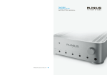
Features
Long distribution pipe and high drop
The outdoor can match with multiple types indoor unit of the same capacity
The indoor unit is identical for heat pump and cooling only unit
Infra red remote controller
Central control and full automation, if connected with a central controller
Optional safety devices and much more precision control device
Auto-restart function
Manual code: SYJS-016-06REV.0
Edition: 2006-06-12
Commercial Air Conditioner
Model: HPU-42CV03
HPU-42HV03
CONTENTS
Contents………………………………………………………...1
1. Description of products & features………………………..2
2. Specification…………………………………………………4
3. Safety precaution……………………………………………7
4. Net dimension of indoor and outdoor……………………..9
5. Installation instructions………..……………………………10
6. Parts and functions…………………………………………21
7. Infrared controller functions………………………………..22
8. Refrigerant diagram....………………………………………39
9. Electrical control functions…………………………………41
10. Diagnostic information (trouble shooting)..……………..47
11. Electrical data....................……………………………….53
1
Commercial Air Conditioner
Model: HPU-42CV03
HPU-42HV03
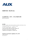
1.DESCRIPTION OF PRODUCTS & FEATURES
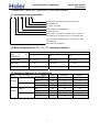
1.1. Products code explanation
H
P
U - 42
C V 03
Power supply type: 03 stands for 200-220V, 50Hz
Design sequence
C: cooling; H: heating
Cooling capacity: 42=42000BTU/h
U: single split unit
Product type : “B” stands for cassette type, “C” stands for
convertible type, ”D” stands for duct, “S” stands for split
type, ”P” stands for cabinet system, "E" stands for ceiling
concealed type.
Haier Brand Air Conditioner
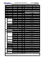
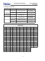
1.2 Brief Introduction for T1、T2、T3 working condition
Climate type
Type
of
Conditioner
Air
T1
T2
T3
Cooling Only
18 ℃~43℃
10℃~35℃
21℃~52℃
Heat pump
-7℃~43℃
-7℃~35℃
-7℃~52℃
Electricity Heating
~43℃
~35℃
~52℃
1.3 Operating Range of Air Conditioners
Temp.
Mode
Indoor
Cooling
Outdoor
Indoor
Heating
Outdoor
Rated
Maximum
Minimum
DB
℃
27
32
15
WB
℃
19
23
14
DB
℃
35
43
-5
WB
℃
24
26
6
DB
℃
20
27
10
WB
℃
14.5
---
--
DB
℃
7
23
-10
WB
℃
6
18
---
2
Commercial Air Conditioner
Model: HPU-42CV03
HPU-42HV03
1.5 Product features
1.5.1 Outdoor unit .
Flexible and easy installation
The outdoor can meet the higher request of installation. From the specifications, you will find for
each unit, how long and how high the piping will be, which will be convenient for design and installation.
Optional safety devices and much more precision control device
a. Ambient temperature sensor, coil temperature sensor and compressor temperature sensor
make the temperature control and defrosting control more precise.
b. High/low pressure switch can feel the discharging pipe pressure and suction pipe pressure on
time and precisely. If the pressure is too low or too high, it will stop the compressor to prevent it
being damaged for the sake of pressure.
c. 3 minutes delay protection for the compressor, the device can protect the compressor from
some damages and make the compressor have a long life.
Silent operation
1.5.2 Steady cabinet indoor unit
Powerfull running & long distance air sending
The unit can run powerfully and supply large volume of cooled air to the room. Long distance and
large angle air sending ensures average temperature distribution, bring you much more comfortable
indoor environment in the shortest time.
Newly designed display panel, more simple
On the display panel there are power, operation, timer, and electric heating indicator, from which
you can find the operation state directly, and the indicator flash times can show the failure.
Malfunction Auto-checking
Failure codes displayed by LED or controllers are so detailed for us to find the fail place more
quickly, and can judge the failure content easily.
Powerfull/Soft function
Special button on remoto controller is used to set powerful working or soft working.
Single fan outdoor, more compact
Central control function, if connected with a detector and a central
controller
3
Commercial Air Conditioner
Model: HPU-42CV03
HPU-42HV03
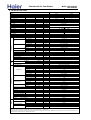
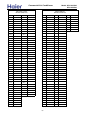
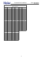
2. SPECIFICATION
PIPING
Outdoor unit
Panel
Indoor unit
item
Model
Function
Capacity
Capacity
Sensible heat ratio
Total power input
Max. power input
EER or COP
Dehumidifying capacity
Power cable
Signal cable
Connecting cable
Wired control cable
for wired control unit
Power source
Running /Max.Running current
Start Current
Class of anti electric shock
Circuit breaker
Max. operating pressure of heat side
Max. operating pressure of cold side
Unit model (color)
Type × Number
Speed(H-M-L)
Fan
Fan motor output power
Air-flow(H-M-L)
Type / Diameter
Heat exchanger
Total Area
Temp. scope
External
(L×W×H)
Dimension
Package
(L×W×H)
Air sending angle
Drainage pipe (material , I.D./O.D.)
Control type (Remote /wired /model)
Fresh air hole dimension
Outlet distribution hole dimension
Electricity Heater
Noise level
(H-M-L)
Weight
(Net / Shipping)
External
(L×W×H)
Dimension
Package
(L×W×H)
Weight
(Net / Shipping)
Unit model (color)
Model / Manufacture
Oil model
Oil type
Compressor
Oil charging
Type
Protection type
Starting method
Type × Number
Speed
Fan
Fan motor output power
Air-flow(H-M-L)
Type / Diameter
Heat exchanger
Row / Fin pitch
Temp. scope
External
(L×W×H)
Dimension
Package
(L×W×H)
Drainage pipe (material , I.D./O.D.)
Refrigerant control method
Defrosting
Volume of Accumulator
Noise level
Type of Four way valve
material of reduce noise
crankcase heater power
Weight
(Net / Shipping)
Type / Charge
Refrigerant
Recharge quantity
Liquid
Pipe
Gas
Connecting Method
MAX.Drop
Between I.D &O.D
MAX.Piping length
HPU-42CV03
BTU/h
kW
W
W
W/W
10‐³×m³/h
section
section
section
section
N, V, Hz
A/A
A
A
Mpa
Mpa
r/min
kW
m³/h
mm
m²
℃
mm×mm×mm
mm×mm×mm
heating
----
cooling
41000
12.0
70%
3700
4400
3.24
------------5.0
5G×2.5mm2
4G×0.75mm2
/
/
3N,380-400V,50HZ
Cooling 6.9A/7.8A Heating 7.0/8.3
50
CLASS I
---20
2.8
---2.8
---HPU-42CV03(WHITE)
centrifugal
430/405/370
0.09
1750
inner grooved/φ7
0.45
1850×600×350
1980×660×420
mm
mm
mm
kW
dB(A)
kg / kg
mm×mm×mm
mm×mm×mm
kg / kg
r/min
kW
m³/h
mm
Remote
/
/
51
59/70
/
/
/
HPU-42CV03(WHITE)
VR54KS-TFP-542/COPELAND
3GS
1360
SCROLL
Inner thermal protection
hard startup
Axial*2
840
0.06
6000
inner grooved/φ9.52
2/1.6
℃
mm×mm×mm
mm×mm×mm
mm
mm/mm
L
dB(A)
W
kg / kg
g
g/m
mm
mm
m
m
948*340*1250
1090*410*1350
Capillary tube
Automatic
/
59
/
/
/
106/111
R22/3400
65
φ9.52
φ19.05
Flared
30
50
Norminal condition: indoor temperature (cooling): 27℃DB/19℃WB, indoor temperature (heating): 20℃DB
Outdoor temperature(cooling): 35℃DB/24℃WB, outdoor temperature(heating): 7℃DB/6℃WB
The noise level will be measured in the third octave band limited values, using a Real Time Analyser calibrated sound intensity meter. It is a sound pressure noise level.
The detailed method please refer to the following information:
Commercial Air Conditioner
PIPING
Outdoor unit
Panel
Indoor unit
item
Model
Function
Capacity
Capacity
Sensible heat ratio
Total power input
Max. power input
EER or COP
Dehumidifying capacity
Power cable
Signal cable
Connecting cable
Wired control cable
for wired control unit
Power source
Running /Max.Running current
Start Current
Class of anti electric shock
Circuit breaker
Max. operating pressure of heat side
Max. operating pressure of cold side
Unit model (color)
Type × Number
Speed(H-M-L)
Fan
Fan motor output power
Air-flow(H-M-L)
Type / Diameter
Heat exchanger
Total Area
Temp. scope
External
(L×W×H)
Dimension
Package
(L×W×H)
Air sending angle
Drainage pipe (material , I.D./O.D.)
Control type (Remote /wired /model)
Fresh air hole dimension
Outlet distribution hole dimension
Electricity Heater
Noise level
(H-M-L)
Weight
(Net / Shipping)
External
(L×W×H)
Dimension
Package
(L×W×H)
Weight
(Net / Shipping)
Unit model (color)
Model / Manufacture
Oil model
Oil type
Compressor
Oil charging
Type
Protection type
Starting method
Type × Number
Speed
Fan
Fan motor output power
Air-flow(H-M-L)
Type / Diameter
Heat exchanger
Row / Fin pitch
Temp. scope
External
(L×W×H)
Dimension
Package
(L×W×H)
Drainage pipe (material , I.D./O.D.)
Refrigerant control method
Defrosting
Volume of Accumulator
Noise level
Type of Four way valve
material of reduce noise
crankcase heater power
Weight
(Net / Shipping)
Type / Charge
Refrigerant
Recharge quantity
Liquid
Pipe
Gas
Connecting Method
MAX.Drop
Between I.D &O.D
MAX.Piping length
Model: HPU-42CV03
HPU-42HV03
HPU-42HV03
BTU/h
kW
W
W
W/W
10‐³×m³/h
section
section
section
section
N, V, Hz
A/A
A
A
Mpa
Mpa
r/min
kW
m³/h
mm
m²
℃
mm×mm×mm
mm×mm×mm
cooling
41000
12.0
70%
heating
44000
13.0
3700
4400
3.24
4000
4900
3.25
5.0
5G×2.5mm2
4G×0.75mm2
/
/
3N,380-400V,50HZ
Cooling 6.9A/7.8A Heating 7.0/8.3
50
CLASS I
CLASS I
20
2.8
2.8
2.8
2.8
HPU-42HV03(WHITE)
centrifugal
430/405/370
0.09
1750
inner grooved/φ7
0.45
1850×600×350
1980×660×420
mm
mm
mm
kW
dB(A)
kg / kg
mm×mm×mm
mm×mm×mm
kg / kg
r/min
kW
m³/h
mm
Remote
/
/
51
59/70
/
/
/
HPU-42HV03(WHITE)
VR54KS-TFP-542/COPELAND
3GS
1360
SCROLL
Inner thermal protection
hard startup
Axial*2
840
0.06
6000
inner grooved/φ9.52
2/1.6
℃
mm×mm×mm
mm×mm×mm
mm
mm/mm
L
dB(A)
W
kg / kg
g
g/m
mm
mm
m
m
948*340*1250
1090*410*1350
Capillary tube
Automatic
/
59
/
/
40
106/111
R22/3400
65
φ9.52
φ19.05
Flared
30
50
Norminal condition: indoor temperature (cooling): 27℃DB/19℃WB, indoor temperature (heating): 20℃DB
Outdoor temperature(cooling): 35℃DB/24℃WB, outdoor temperature(heating): 7℃DB/6℃WB
The noise level will be measured in the third octave band limited values, using a Real Time Analyser calibrated sound intensity meter. It is a sound pressure noise level.
The detailed method please refer to the following information:
Commercial Air Conditioner
Model: HPU-42CV03
HPU-42HV03
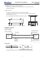
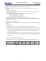
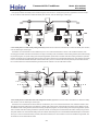
Installation state: the unit should be placed on the flat floor or be mounted in
horizontal direction.
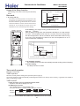
Testing method:
standing-on-floor unit: If the unit cooling capacity is over 28000W, the noise level should be
measured at the front, left, right directions respectively.
1m
1m
1m
outdoor unit:
1.air outlet from side: the noise level is the average sound pressure level measured from front, left,
right directions.
2.air outlet from top: the noise level is the average sound pressure level measured from front, back,
left, right directions.
measured point:
H ( height to the ground) = (h (unit height) + 1m) /2
and, it is 1m to each side.
1m
1m
1m
h
Note: ⊙ is the real time
6
Commercial Air Conditioner
Model: HPU-42CV03
HPU-42HV03
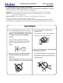
3. Safety precaution of indoor and outdoor
Carefully read the following information in order to operate the airconditioner correctly.
Below are listed three kinds of Safety Cautions and Suggestions.
WARNING! Incorrect operations may result in severe consequences of death or serious injuries.
CAUTION! Incorrect operations may result in injuries or machine damages; in some cases may
cause serious consequences.
INSTRUCTIONS: These information can ensure the correct operation of the machine.
Be sure to conform with the following important Safety Cautions.
The Safety Cautions should be at hand so that they can be checked at any time when needed.
If the conditioner is transferred to the new user, this manual should be as well transferred to the new user.
WARNING!
If any abnormal phenomena is found
(e. g.smell of firing), please cut off the
power supply immediately, and contact
the dealer to find out the handling
method.
Don't dismantle the outlet of the
outdoor unit.
The exposure of fan is very dangerous
whichmay harm human beings.
In such case, to continue using the
conditioner will damage the conditioner,
and may cause electrical shock or fire
hazard.
switch
off
When need maintenance and repairment,
call dealer to handle it.
After a long time use of air-conditioner
the base should be checked for any
damages.
If the damaged base is not repaired, the
unit may fall down and cause accidents.
7
Incorrect maintenance and repairment
may cause water leak, electrical shock
and fire hazard.
Commercial Air Conditioner
Model: HPU-42CV03
HPU-42HV03
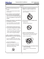
WARNING!
Installed electrical-leaking circuit
breaker.
No goods or nobody is permitted to
placed on or stand on outdoor unit.
It easily cause electrical shock without
circuit breaker.
The falling of goods and people may
cause accidents.
Air-conditioner can't be installed in
the environment with inflammable
gases because the inflammable gases
near to air-conditioner may cause fire
hazard.
Please let the dealer be responsible for
installing the conditioner.
Don't operate the air-conditioner with
damp hands.
Incorrect installation may cause water
leak, electrical shock and fire hazard.
Otherwise will be shocked.
Call the dealer to take measures to
prevent the refrigerant from leaking.
If conditioner is installed in a small
room be sure to take every measure in
order to prevent suffocation accident
Only use correctly-typed fuse.
even in case of refrigerant leakage.
May not use wire or any other materials
replacing fuse, other-wise may cause
faults or fire accidents.
When conditioner is deinstalled or
reinstalleddealer should be responsible
for them.
Incorrect installation may cause water
leaking, electrical shock and fire hazard.
Connect earthing wire.
Earthing wire should not be connected to the gas pipe, water pipe,
lightning rod or phone line, in-correct
earthing may cause shock.
Use discharge pipe correctly to ensure
efficient discharge.
Incorrect pipe use may cause water
leaking.
Earthing
8
Commercial Air Conditioner
Model: HPU-42CV03
HPU-42HV03
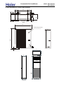
4. Net dimension of indoor and outdoor
38
580
185
30
52
70
38
18
340
380
18
185
Screw Hole
(M10)
88
950
25
1250
Power wiring Terminal
350
600
1851
350
16
336
500
Commercial Air Conditioner
Model: HPU-42CV03
HPU-42HV03
5. Installation Instructions
5.1 Outdoor unit installation
Necessary Tools:
1.Screwdriver
2.Hacksaw
3.70mm diameter hole drill
4.Spanner(dia.17,27mm)
5.Spanner(dia.14,17,27mm)
6.Pipe cutter
7.Flaring tool
8.Knife
9.Nipper
10.Gas leakage detector
or soap water
11.Tape measure
12.Reamer
13.Refrigerant oil
Installation Position
●Place strong enough to support the unit weight, and will not cause vibration and noise.
●Place where discharged air and noise do not cause interference to the neighbors, and is sufficiently
ventilated.
●Place where is less affected by rain or direct sunlight and sea breeze.
●Place with enough space to ventilation
●The unit cannot be installed on an unspecified metal frame
●It shall not be less than 2.5m high from the ground to the unit if installed close to the street
●Easy for maintenance
Fixing of the unit
1.Position of the wall hole
The hole through the wall must be decided as per installation place and pipe direction. Please refer to the
installation drawings.
2. Making the wall hole
Drill a hole of 120*70mm with a little slope to the exterior through the wall as follows:
10
Commercial Air Conditioner
Model: HPU-42CV03
HPU-42HV03
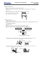
Installation Space
Installation where the area with strong winds.
Install the unit so that the air outlet section of the unit must NOT be faced
toward wind direction.
Fixing of the unit
380
Fix outdoor unit using M10 bolt to concrete floor horizontally.
If installed on the wall or on top of a roof, bracket should be fixed securely to
resist earthquake or storms.
Use rubber pad during installation against unit vibration.
over 30cm
580
190
190
over 10cm
over 10cm
over 15cm
over 60cm
Installation dimension of outdoor unit(mm)
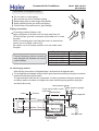
Refrigerant piping
Outline piping
3-way stop valve
Flare connection
Gas pipe
Indoor
unit
Outdoor
unit
Liquid
pipe
2-way stop valve
Piping size
Liquid pipe
9.52x0.8mm
Gas pipe
15.88x1.0mm
90+0.5
Connect the flare nuts to the pipes, and then flare the pipes.
11
Commercial Air Conditioner
Model: HPU-42CV03
HPU-42HV03
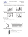
Precautions for refrigerant piping
Do not twist or crush piping.
Be sure that no dust is mixed in piping.
Bend piping with as wide angle as possible.
Keep insulating both gas and liquid piping.
Check flare-connected area for gas leakage.
Piping connection
Connecting method (indoor unit)
Apply refrigerant oil at half union as large and flare nut.
To bend a pipe, give the roundness as possible not to crush
the pipe.
When connecting pipe, hold the pipe centre to centre then
screw nut on by hand, refer to Fig.
Be careful not to let foreign matters, such as sands enter
the pipe.
Pipe diameter
Liquid pipe 6.35mm
Liquid pipe 9.52mm
Gas pipe 12.7mm
Gas pipe 15.88mm
Gas pipe 19.05mm
Forced fastening without centering
may damage the threads and cause
a gas leakage.
Fastening torque
14.2-17.2N.m
32.7-39.9N.m
49.5-60.3N.m
61.8-75.4N.m
97.2-118.6N.m
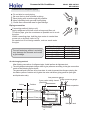
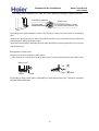
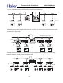
Air discharging method
After finishing connection of refrigerant pipe, it shall perform air tightness test.
The air tightness test adopts nitrogen tank to give pressure according to the pipe connection
mode as the following figure shown.
The gas and liquid valve are all in close state. In order to prevent the nitrogen entering the
circulation system of outdoor unit, tighten the valve rod before giving pressure (both gas
and liquid valve rods).
Low pressure gauge
3-way valve totally closed
(Gas side)
Indoor
Outdoor
VLVH
Completely tightened Flare part
Meter separator
Discharging valve
Completely tightened Flare part
Indoor units
High pressure gauge
Mainhole
Dropping valve
Outdoor units
2-way valve totally closed
(Liquid side)
12
Nitrogen tank
Commercial Air Conditioner
Model: HPU-42CV03
HPU-42HV03
Precautions for refrigerant piping
Do not twist or crush piping.
Be sure that no dust is mixed in piping.
Bend piping with as wide angle as possible.
Keep insulating both gas and liquid piping.
Check flare-connected area for gas leakage.
Piping connection
Connecting method (indoor unit)
Apply refrigerant oil at half union as large and flare nut.
To bend a pipe, give the roundness as possible not to crush
the pipe.
When connecting pipe, hold the pipe centre to centre then
screw nut on by hand, refer to Fig.
Be careful not to let foreign matters, such as sands enter
the pipe.
Pipe diameter
Liquid pipe 6.35mm
Liquid pipe 9.52mm
Gas pipe 12.7mm
Gas pipe 15.88mm
Gas pipe 19.05mm
Forced fastening without centering
may damage the threads and cause
a gas leakage.
Fastening torque
14.2-17.2N.m
32.7-39.9N.m
49.5-60.3N.m
61.8-75.4N.m
97.2-118.6N.m
Air discharging method
After finishing connection of refrigerant pipe, it shall perform air tightness test.
The air tightness test adopts nitrogen tank to give pressure according to the pipe connection
mode as the following figure shown.
The gas and liquid valve are all in close state. In order to prevent the nitrogen entering the
circulation system of outdoor unit, tighten the valve rod before giving pressure (both gas
and liquid valve rods).
Low pressure gauge
3-way valve totally closed
(Gas side)
Indoor
Outdoor
VLVH
Completely tightened Flare part
Meter separator
Discharging valve
Completely tightened Flare part
Indoor units
High pressure gauge
Mainhole
Dropping valve
Outdoor units
2-way valve totally closed
(Liquid side)
13
Nitrogen tank
Commercial Air Conditioner
Model: HPU-42CV03
HPU-42HV03
First step: 0.3MPa (3.0kg/cm2g) pressurize over 3 minutes.
Second step: 1.5Mpa (15kg/cm2g) pressurize over 3 minutes. Large leakage will
be found.
Third step: 3.0 MPa (30kg/cm2g) pressurize about 24 hours. Little leakage will be
found.
Check if the pressure drops
If the pressure does not drop, the unit is passed
If the pressure drops, please check the leaking point.
After pressurizing for 24 hours, each 1 C difference of ambient temperature
will result in 0.01MPa(0.1kg/cm2g) pressure change. It shall be corrected during test.
Checking the leaking point
From the first to third steps, if the pressure drops, check the leakage in each joint
by the sense of hearing, feeling or soap water, etc. to find the leaking point.
After confirming the leaking point, welding it again or tighten the nut tightly again.
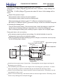
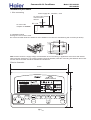
Piping and indoor unit vacuumizing
Use vacuum pump to perform vacuumizing. It is strictly forbidden to use the
refrigerant to remove the air inside the system.
After air tightness test and discharging all the nitrogen, connect the vacuum pump
as the following figure shown.
Indoor
Outdoor
Completely tightened
Low pressure gauge
3-way valve totally closed
(Gas side)
VLVH
Flare part
High pressure gauge
Meter separator
Discharging valve
P
Completely tightened
Indoor units
Flare part
Vacuum pump
Outdoor units
2-way valve totally closed
(Liquid side)
It shall use the vacuum pump of (lower than -755mmHg)high vacuum degree and large air
discharging (over 40l/min).
The vacuumizing time depends on the length of the connecting pipe, generally is 1~2 hours.
When vacuumizing, it shall be confirmed both gas and liquid side valves are closed.
If after 2 hours vacuumizing, it cannot reach the vacuum degree below -755mmHg, it can be
vacuumized for other 1 hour.
If after 3 hours vacuumizing, it still cannot reach the vacuum degree below -755mmHg, check
if there is any leaking point and repair the them.
14
Commercial Air Conditioner
Model: HPU-42CV03
HPU-42HV03
If after over 2 hours vacuumizing, the vacuum degree is below -755mmHg, close the VL and VH on the
meter separator and stop vacuumizing. 1 hour later to confirm if the vacuum degree changes. If changes,
it indicates there is leaking point in the system. Check the leaking point and
repair.
After finishing the above vacuumizing, change the vacuum pump into refrigerant pump to charge the
refrigerant.
Charging amount of refrigerant
When the total length (L) of the two indoor units' connecting pipe is less than 5m, it is unnecessary to
charge additional refrigerant.
If the connecting pipe (L) exceeds 5m, it shall charge Mg additional refrigerant per meter.
That is: Refrigerant charging amount = (L-5) x M (g)
For the unit with liquid pipe 6.35mm, M=30
For the unit with liquid pipe 9.52mm, M=65
Only in COOLING operation can charge the additional refrigerant.
When charging, the refrigerant shall be charged from the charging nozzle of low pressure vavle.
Be carefull when charging refrigerant, do not let the air mix into the system,and must charge the additional
refrigerant in liquid condition.
Piping connection of outdoor unit.
Connect the connecting pipe and inlet and outlet liquid pipe according to the piping
method.
Purging method
Discharge the air out of the indoor unit and the refrigerant pipe by vacuumizing
(1) Fasten all the nuts of the indoor and outdoor pipes to make these parts out of leakage.
(2) Under the condition of the complete close of the indoor and outdoor valve center (both
liquid and gas side),dismount the repair valve cap.Vacuumizing through the charge
mouth of the repair valve.
(3) After vacuumizing fasten the repair valve,and dismount the cap of the big and small
stop valve,then loosen the stop valve center completely and fasten the big and small
stop valve.
Extra charging amount of the refrigerant
When piping is longer than 5 m, charge additional refrigerant specified in this list.
Pipe length
Refrigerant charge (g)
5m
10m
15m
20m
25m
30m
375
750
1125
1500
1875
15
Commercial Air Conditioner
Model: HPU-42CV03
HPU-42HV03
5.2 Indoor unit installation
B]gd`Um cZ k\c`Y ib]h
Pfm hc Vf]b[ h\Y dUW_YX ib]h hc h\Y ]bghU``Uh]cb d`UWY1
S\Yb ]h ]g bYWYggUfm hc ibdUW_ h\Y ib]h/ VY WUfYZi` bch hc XUaU[Y h\Y ib]h1 SfUd ]h k]h\
bm`cb YhW1
?ZhYf ibdUW_]b[/ VY gifY hc d`UWY h\Y ib]h k]h\ h\Y Zfcbh g]XY hc VY id1
BY`]jYfm
KchY= S\Yb XY`]jYf]b[/ Xcb,h \c`X d`Ugh]W
DUW]b[ id
dUfhg giW\ Ug ]b`Yh cf cih`Yh [f]`` YhW1
D]l]b[ cZ h\Y ib]h
Mcg]h]cb cZ h\Y kU`` \c`Y
SU`` \c`Y g\ci`X VY XYW]XYX UWWcfX]b[ hc ]bghU``h]cb d`UWY UbX d]d]b[ X]fYWh]cb1 -fYZYf
hc ]bghU``Uh]cb XfUk]b[g.
JU_]b[ U \c`Y
Bf]`` U \c`Y cZ :3aa X]U1 k]h\ U `]hh`Y g`cdY hckUfXg cihg]XY1
GbghU`` d]d]b[ \c`Y WcjYf UbX gYU` ]h k]h\ dihhm UZhYf ]bghU``Uh]cb1
GKBLLN OGBC
LQPBLLN OGBC
kU`` \c`Y
kU`` h\]W_bYgg
:3aa
- Afcgg gYWh]cb cZ kU`` \c`Y .
With the unit set up vertically,fix the fitting metal to the unit with screws, then fix the
fitting metal to the wall with cement nail and washer, as shown below:
Cement nail
Fitting metal
330
2- 10 hole
Screw
Moreover, if want to fix the unit more firmly, you should fix the bottom panel to the
ground with concrete bolts,as shown below:
202
79
260
130
Fitting hole
Bottom Panel
16
(202) (79)
4- 14 hole 30 depth
Commercial Air Conditioner
Model: HPU-42CV03
HPU-42HV03
x045{..{5-10 1* {05-q*{.. 2.{5~v
D]l h\Y Ubh]0ZU`` d`UhY hc h\Y kU`` k]h\ gWfYkg gc h\Uh h\YfY ]g bc W`YUfUbWY VYhkYYb h\Ya1
S]h\ h\Y ib]h gYh id jYfh]WU``m/ Z]l h\Y Ubh]0ZU`` d`UhY hc h\Y ib]h k]h\ gWfYkg k\]`Y aU_]b[ Ub
UX^ighaYbh Uh h\Y `cb[ dcfh]cb cZ h\Y \c`Y gc h\Uh h\YfY ]g bc W`YUfUbWY VYhkYYb h\Y iddYf
gifZUWY UbX h\Y Ubh]0ZU`` d`UhY1
x045{..{5-10 1* yq4,{2~} /~5{.
D]l hc h\Y ib]h k]h\ gWfYkg gc h\Uh h\YfY ]g bc W`YUfUbWY VYhkYYb h\Y Ubh]0ZU`` d`UhY UbX h\Y ib]h1
?ZhYf WcbZ]fa]b[ h\Uh h\Y ib]h \Ug VYYb gYh id jYfh]WU``m hc h\Y Z`ccf/ Z]l ]h hc h\Y Z`ccf k]h\ Vc`h1
z-2-0+ |100~|5-10
41 AcbbYWh]b[ aYh\cX
?dd`m fYZf][YfUbh c]` Uh \U`Z ib]cb UbX Z`UfY bih1
Pc VYbX U d]dY/ []jY h\Y fcibXbYgg Ug `Uf[Y Ug dcgg]V`Y bch hc WfUg\ h\Y d]dY1
S\Yb WcbbYWh]b[ d]dY/ \c`X h\Y d]dY WYbhfY hc WYbhfY h\Yb gWfYk bih cb Vm \UbX/fYZYf
hc D][1
@Y WUfYZi` bch hc `Yh gibXf]Yg/ giW\ Ug gUbXg YbhYf h\Y d]dY1
DcfWYX ZUghYb]b[ k]h\cih WYbhYf]b[ aUm
XUaU[Y h\Y h\fYUXg UbX WUigY U [Ug `YU_U[Y1
M]dY X]U
I]ei]X d]dY <185aa-62;+.
DUghYb]b[ hcfeiY
5<17K1a
EUg d]dY 4<138aa-627+.
44:1:K1a
51 M]d]b[ WcbbYWh]cb cZ ]bXccf ib]h
?ffUb[YaYbh cZ d]d]b[ UbX XfU]bU[Y d]dY
¿“/„
˜
£
˚
‰•
¸
˛´¶¨+
˛´¶¨-
‰
¡
¿
?ZhYf cdYb]b[ ]b`Yh [f]``/ mci k]`` gYY U Wcbhfc`
Vcl Ug g\ckb ]b h\Y D][1
NYacjY h\Y WcjYf VYZcfY k]f]b[ kcf_1
17
Commercial Air Conditioner
Model: HPU-42CV03
HPU-42HV03
Cut away, with a hammer or a saw, the lid for piping according to piping direction.
Insulation material
Drain hose
Connecting electric cable
for indoor and outdoor unit
Copper tube
According to the piping method, connect the piping on indoor unit with union of connecting
pipe.
Arrange the piping as per the wall hole and bind drain hose connecting electric cable and
piping together with polyethylene tape.
Insert the bound piping connecting electric cable and drain hose through wall hole to connect
with outdoor unit.
Arrangement of drain hose
Drain hose shall be placed in under place.
There should be a slope when arrange drain hose. Avoid up and down waves in drain hose.
Indoor unit
Up
Slope
Down
Good
Bad
If humidity is high, drain pipe( especially in room and indoor unit ) must be covered
with insulation material.
18
Commercial Air Conditioner
Model: HPU-42CV03
HPU-42HV03
w.~|53-| 7-3-0+
KchY=
C`YWhf]W k]f]b[ aigh VY XcbY Vm eiU`]Z]YX dYfgcb1
QgY WcddYf k]fY cb`m/ h\Y dUfUaYhYf cZ WcbbYWh]b[ WUV`Y ]g F3:NK0D 7E 31:8aa51
P\Y dckYf WUV`Y g\ci`X VY cjYf 8E518aa5/ h\Y dckYf WUV`Y ]g gY`Z0dfcj]XYX1
P\Y dckYf gidd`m WcbbYWhg Zfca h\Y cihXccf ib]h1
S]f]b[ cZ ]bXccf ib]h
GbgYfh h\Y WUV`Y Zfca cihg]XY h\Y kU`` \c`Y k\YfY d]d]b[ U`fYUXm Yl]gh1
Mi`` ]h cih Zfca Zfcbh1
IccgYb hYfa]bU` gWfYkg UbX ]bgYfh WUV`Y YbX Zi``m ]bhc hYfa]bU` V`cW_/ h\Yb h][\hYb ]h1
Mi`` h\Y WUV`Y [Ybh`m hc aU_Y gifY ]h ]g h][\h1
LH
KL
NYd`UWY WcjYf UZhYf k]f]b[1
hYfa]bU` V`cW_
S]f]b[ cZ cihXccf ib]h
GbgYfh h\Y WUV`Y Zfca ]bg]XY h\Y kU`` \c`Y
k\YfY d]d]b[ U`fYUXm Yl]ghg1
Mi`` ]h cih Zfca Zfcbh1
IccgY hYfa]bU` gWfYk UbX ]bgYfh WUV`Y YbX Zi``m
]bhc hYfa]bU` V`cW_/ h\Yb h][\hYb ]h1
Mi`` h\Y WUV`Y [Ybh`m hc aU_Y gifY ]h ]g h][\h1
NYd`UWY WcjYf UZhYf k]f]b[1
HPU-42CV03
hUV`Y W`Uad
HPU-42HV03
1 2 3
Y/G
Y/G
R S TN 1 2 3
POWER SUPPLY
KchY=
S\Yb WcbbYWh]b[ ]bXccf UbX cihXccf k]fY/ W\YW_ h\Y biaVYf cb ]bXccf UbX cihXccf
hYfa]bU` V`cW_g1 PYfa]bU`g cZ gUaY biaVYf UbX gUaY Wc`cf g\U`` VY WcbbYWhYX Vm
h\Y gUaY k]fY1
GbWcffYWh k]f]b[ aUm XUaU[Y U]f WcbX]h]cbYf,g Wcbhfc``Yf cf WUigY cdYfUh]cb ZU]`ifY1
19
Commercial Air Conditioner
Model: HPU-42CV03
HPU-42HV03
Ov
O
ver
10
er
10
Over 10cm
Indoor & outdoor unit connection
pipe direction
cm
0cm
Left
Rear
O v
e r
Right
Bottom
* / *
*
*
*
*
* *
+
* *
*
*
Ov
10
er
cm
Over
10cm
Ove
r 15c
m
O
r
ve
60
cm
20
Commercial Air Conditioner
Model: HPU-42CV03
HPU-42HV03
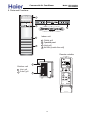
6. Parts and Functions
1
ON/OFF
MODE
FAN
SET
HUMI
TEMP
ON/OFF
MODE
FAN
SET
HEALTH
HUMI
TIMER
TEMP
SLEEP
**+
**-
*
HEALTH
TIMER
SLEEP
TEMP +
TEMP -
HEALTH
2
*
SET
HUMI
TEMP
3
Indoor unit
1
2
4
2
HEALTH
TIMER
SLEEP
3
4
Outlet grill
Operation panel
Inlet grill
Air filter [inside the unit]
Remote controller
Outdoor unit
Inlet grill
2 Outlet grill
1
TEMP
1
ON
OFF
HEALTH
2
FAN
MODE
SLEEP
SWING
CLOCK
SET
TIMER
HEAT
RESET
21
LIGHT
LOCK
Commercial Air Conditioner
Model: HPU-42CV03
HPU-42HV03
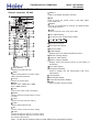
7. Infrared controller functions
Remote controller YR-H49
20
11
21
B
22
A
19
27
18
28
17
25
24
23
26
16
15
14
TEMP
ON
OFF
11
HEALTH
1
FAN
12
HEALTH
Used to set Health operation function
FAN
Used to select fan speed: AUTO, LOW FAN, MED
FAN, HIGH FAN.
12
13 SWING
Used to set UP/DOWN air sending and RIGHT/LEFT
air sending direction.
TEMP
Used to set temp.,temp. range:16 C~30 C
14
15 Timer ON/OFF display
16 Fan speed and air sending direction display
MODE
2
LOW
SLEEP
SWING
8
CLOCK
SET
3
TIMER
7
6
RESET
LIGHT
HIGH
AUTO
13
17 Swing direction display
9
18 Room temperature display
4
HEAT
MID
19 Sleep
29
LOCK
5
10
state display
Health display
Display when set Health operation function.
21 Electric Heating display
20
22
Fresh Air state display
Battery Capacity display
Display when the electric power of the battery is
insufficient.
24 Lock state display
25 Temperature display
Used to display the set temperature and room
temperature.
26 Clock display
27 Humidifying display
28 Power/Soft operation display
29 HEAT
Select Auxiliary electric heater
23
1 Power ON/OFF
Used for unit start and stop.
2 MODE
Used to select AUTO run,COOL, DRY,
HEAT and FAN operation.
3 CLOCK
Used to set correct time.
4 TIMER
Used to select TIMER ON, TIMER
OFF, TIMER ON/OFF.
5 LOCK
Used to lock buttons and LCD display.
6 RESET
Used to reset the controller back to normal
condition.
7 HOUR
Used to set clock and timer setting.
SLEEP
Used to select sleep mode
9 SET
Used to confirm Timer and Clock setting.
10 LIGHT
Control the light up and go out of the control
panel's background light source and control
the switch of the buzzer.
8
Note: All the above functions will be a little different for the specific models.
Commercial Air Conditioner
Model: HPU-42CV03
HPU-42HV03
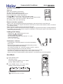
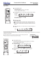
Operation instructions
Clock set
MODE
SLEEP
When unit is started for the first time
and after replacing batteries in remote
controller, clock should be adjusted as follows:
Press CLOCK button, "AM"or "PM" flashes.
Press or to set correct time. Each press will increase
or decrease 1 min . If the button is kept pressed, time will change quickly.
After time setting is confirmed, press SET, "AM" and "PM"
stop flashing, while clock starts working.
SWING
SET
CLOCK
1
TIMER
3
2
HEAT
RESET
LIGHT
LOCK
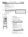
Remote controller's operation
When in use, put the signal transmission head directly to the receiver hole on the indoor unit
The distance between the signal transmission head and the receiver hole should be within 7m without
any obsacles as well.
Don't throw the controller, prevent it from being damaged.
When electronic-started type fluorescent lamp or change-over type fluorescent lamp or wireless telephone
is installed in the room, the receiver is apt to be disturbed in receiving the signal so the distance to the
indoor unit should be shorter.
Loading of the battery
Slightly press " " and push down the cover.
Load the batteries as illustrated.
2 R-03 dry batteries, (cylinder)
Be sure that the loading is in line with the "+"/"-" pole
request as illustrated.
Put on the cover again.
S
TE
NU
MI
Confirmation indicator:
In disorderation, reload the batteries or load the new batteries
after 5 mins.
Note:The waster batteries should be disposed properly,use two
2R-03 dry batteries
new same-type batteries when loading.
If the remote controller cant function normally or doesnt work at
all,use a sharp-pointed item to press the reset key.
Hint:Remove the batteries in case unit wont be in usage for a long period.
If there are any displays after taking-out just need to press reset key.
When throw away the waste batteries, please perform in accordance with the local regulation.
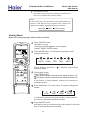
Auto Mode
1
2
Press ON/OFF button
Unit starts running.
The previous status appears on the display
(except. TIMER, SLEEP mode)
TEMP
ON
OFF
HEALTH
4
Press MODE button. For each press,
operation mode changes as follows:
1
FAN
3
MODE
2
SLEEP
SWING
CLOCK
SET
TIMER
HEAT
AUTO COOL
DRY FAN
HEAT
RESET
Select Auto run,
"
" appears and auto run starts.
23
LIGHT
LOCK
Commercial Air Conditioner
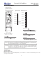
3
Select temp. button
Press TEMP button
Every time the button is pressed, temp.
setting increases 1 C
Every time the button is pressed, temp.
setting decreases 1 C
If the button is kept pressed, setting will
increase or decrease quickly.
4
Press FAN,For each press, operation mode
changes as follows:
Remote
controller
LOW
MID
HIGH
AUTO
Unit runs at the speed displayed on LCD.
When fan speed is AUTO,it is changed automatically
according to the indoor temperature.
Model: HPU-42CV03
HPU-42HV03
Note:
During Auto run operation, temp. setting will be
shown in LCD display, unit will select heating,
cooling or fan operation according to the room
temp.
Press ON/OFF button
Unit stops running.
5
Cooling Mode
1
Press ON/OFF button
Unit starts running.
The previous status appears on the display
(except. TIMER, SLEEP mode)
2
Press MODE button. For each press,
operation mode changes as follows:
TEMP
3
HEALTH
1
ON
OFF
3
FAN
4
5
MODE
2
SLEEP
SWING
CLOCK
SET
Remote
controller
3
TIMER
HEAT
RESET
LIGHT
LOCK
4
AUTO COOL
DRY FAN
HEAT
Select cooling operation, Shows" "
Cooling operation starts.
Select temp. button
Press TEMP button
Every time the button is pressed, temp.
setting increases 1 C
Every time the button is pressed, temp.
setting decreases 1 C
If the button is kept pressed, setting will
increase or decrease quickly.
Press FAN button. For each press, fan speed
changes as follows:
Remote
controller
LOW
MID
HIGH
AUTO
Unit runs at the speed displayed on LCD.
When fan speed is AUTO,it is changed outomatically
according to the indoor temperature.
5
Press ON/OFF button
Unit stops running,and when entry this mode for the
next time,it will show the previous setting.
24
Commercial Air Conditioner
Model: HPU-42CV03
HPU-42HV03
Dry Mode
1
Press ON/OFF button
Unit starts running.
The previous status appears on the display
(except. TIMER, SLEEP mode)
2
Press MODE button. For each press, operation mode changes
as follows:
TEMP
3
HEALTH
1
ON
OFF
3
FAN
Remote
controller
4
5
MODE
2
SLEEP
SWING
CLOCK
SET
HEAT
LIGHT
DRY FAN
Select Drying operation shows"
Dry operation starts
TIMER
RESET
AUTO COOL
HEAT
"
LOCK
3
Select temp. button
Press TEMP button
Every time the button is pressed, temp. setting increases 1 C
Every time the button is pressed, temp. setting decreases 1 C
If the button is kept pressed, setting will increase or decrease
quickly.
4
Press FAN button. For each press, fan speed changes as
follows:
Remote
controller
LOW
MID
HIGH
AUTO
Unit runs at the speed displayed on LCD.
In DRY mode, when room temp.becomes 2 C lower than temp. setting,unit will run intermittently at LOW speed
regardless of FAN setting.
Press ON/OFF butto nUnit stops running, and when entering this mode
for the next time, it will show the previous setting
5
COOL operation starts when room
temp. is higher than temp. setting.
Ultra-low air flow
Temp.setting+2 C
Temp.setting
On reaching 2 C lower than temp.
setting,unitwill run in mild DRY mode.
Fan Mode
1
Press ON/OFF button
Unit starts running.The previous status appears on the display
(except. TIMER, SLEEP mode)
2
Press MODE button. For each press,operation mode
changes as follows:
TEMP
HEALTH
1
ON
OFF
3
MODE
2
SLEEP
SWING
CLOCK
SET
TIMER
HEAT
RESET
Remote
controller
FAN
4
LIGHT
AUTO
COOL
Select Fan operation shows "
3
DRY
FAN
HEAT
", Fan operation starts.
Press FAN button. For each press, fan speed changes as
follows:
LOCK
LOW
MID
HIGH
Unit runs at the speed displayed on LCD.
25
Commercial Air Conditioner
Model: HPU-42CV03
HPU-42HV03
Press ON/OFF button
Unit stops running, and when entering this mode for the
next time, it will show the previous setting.
4
Note:
In this mode, temp. can't be selected, temp.setting will not be
shown in LCD display.In Fan operation mode, "AUTO" fan
speed is not available. Operation cycles are as follows:
LOW
MID
HIGH
Heating Mode
Note: For cooling only type, this function is invalid.
1
Press ON/OFF button
Unit starts running.
The previous status appears on the display
(except. TIMER, SLEEP mode)
2
Press MODE button. For each press,operation mode
changes as follows:
TEMP
3
HEALTH
1
ON
OFF
3
5
SLEEP
SWING
CLOCK
SET
Select Heating operation "
operation starts.
" appears and Heating
Select temp. button
Press TEMP button
Every time the button is pressed, temp. setting increases 1 C
Every time the button is pressed, temp. setting decreases 1 C
If the button is kept pressed, setting will increase or
decrease quickly.
4
Press FAN button. For each press, fan speed changes as
follows:
HEAT
LIGHT
HEAT
3
TIMER
RESET
DRY FAN
4
MODE
2
AUTO COOL
FAN
LOCK
LOW
MID
HIGH
AUTO
In heat mode,warm air will blow out after a short period of
time due to cold-draft prevention function.
5
Press ON/OFF button
Unit stops running, and when entering this mode for the next
time, it will show the previous setting.
26
Commercial Air Conditioner
Model: HPU-42CV03
HPU-42HV03
Air flow adjustment
Swing louvers
(Vertical louvers)
(Horizontal louvers)
Up and down
Side from side
Position 1
Position 1
Position 2
Position 2
Position 3
TEMP
ON
OFF
HEALTH
Position 4
SLEEP
SWING
2
1
Position 5
SET
TIMER
Position 6
HEAT
RESET
Position 4
FAN
MODE
CLOCK
Position 3
LIGHT
Position 5
[COOL/DRY/FA
N/AUTO(COOL)
HAVE NOT]
Position 6
(AUTO SWING)
Position 7
LOCK
Position 8
Fixed position
Press the SWING
again to fix the
vertical louvers at your desired position.
Swing
Side from side
Press SWING
the horizontal
louvers move from up to down.
Swing
Fixed position
Press SWING
the vertical
louvers move from side to side.
Press the SWING
again to fix the
horizontal louvers at your desired position.
Note: Put louvers at up position in cooling and down position in heating mode.
This will be helpful to keep an even room temp.
Notice: In cooling or dry operation, don't put horizontal louvers at downward
position for a long time, or outlet grill might get frosted. Don't expose
your skin to cool or warm air for a long time.
SLEEP Mode
Remote control unit
Before go to bed, you can press the Sleep button, the air conditioner will operate in comfortable sleep mode to make
your sleep more comfortable.
27
Commercial Air Conditioner
Model: HPU-42CV03
HPU-42HV03
Usage of the Sleep function
The Sleep running starts
After starting, set the Run mode and press the Sleep
button.
The Sleep running stops
About 6 hours
Run mode
1. In cooling and dry
1 hour
After starting of the Sleep operation, the temperature Will
be raised for 1 C higher than the set temperature 1 hour
later,and be raised for 1 C after another hour. It continues
under that condition for 6 hours, then the machine will be
switched off. The temperature is higher than the set
temperature so as to avoid catching cold in sleeping.
Raise 1 C
Raise 1 C
1 hour
Close down
the machine
Set the
temperature
In cooling and dry
2. In heating ( the single-cooling conditioners do not
have the
function)
After the Sleep running starts, the temperature will drop for 2 C after another
one hour. The temperature will raise for 1 C after 3 hours running under
the above temperature, and the conditioner will be closed down after running
for 3 hours. The temperature is lower than the set temperature so as to
avoid uneasiness in sleeping.
TEMP
ON
OFF
HEALTH
Close down
the machine
Set the
temperature
FAN
MODE
SLEEP
SWING
CLOCK
SET
1 hour
Drop for 2 C
1 hour
Drop for 2 C
TIMER
HEAT
Raise 1 C
3 hours
RESET
LIGHT
About 3 hours
LOCK
The Sleep running starts
In heating
The Sleep running stops
3. In automatic running
The conditioner will run under automatically selected working mode of sleeping.
4. In Fan running
The Sleep function is invalid.
Timer on/off operation
Remote control unit
TIMER operation
Set Clock correctly before starting Timer operation (refer to page 2)
You can let unit start or stop automatically at following times: Before you wake up in the morning, or get back from outside or
after you fall asleep at night.
TIMER ON/OFF
(1) After unit start, select your desired operation mode.
Operation mode will be displayed on LCD.
(2) TIMER mode selection
Press TIMER button to change TIMER mode.
Every time the button is pressed, display changes as follows:
Remote
controller
ON
AM 12:00
TIMER ON
OFF
PM 12:00
TIMER OFF
ON
AM 12:00
OFF
PM 12:00
BLANK
TIMER ON-OFF
Select your desired TIMER mide (TIMER ON or TIMEROFF) ON or OFF will flash.
28
Commercial Air Conditioner
Model: HPU-42CV03
HPU-42HV03
(3) Timer setting
Press HOUR / button.
Every time the button is pressed, time increases 1 min, If button is kept
pressed, time will change quickly.
Every time the button is pressed, time decreases 1 min, If button is kept
pressed, time will change quickly. Time will be shown on LCD. It can be
adjusted within 24 hours.
(4) Confirming your setting
After setting correct time, press SET button to confirm, " ON "
or " OFF " stops flashing.
Time displayed: Unit starts or stops at x hour x min (TIMER
ON or TIMER OFF)
Timer mode indicator on indoor unit lights up.
TEMP
ON
OFF
HEALTH
FAN
MODE
To cancel TIMER mode
SLEEP
SWING
CLOCK
SET
TIMER
Just press TIMER button several times until TIMER mode disappears.
HEAT
LIGHT
RESET
LOCK
Hints
After replacing batteries or a power failure happens, Time setting should be reset.
Remote controller possesses memory function when use TIMER mode next time, just Press SET button after
mode selecting if timer setting is the same as previous one.
Timer on-off function
Remote controller operation TIMER ON-OFF
(1) After unit start, select your desired operation mode.
Operation mode will be displayed on LCD.
(2) TIMER mode selection
Press TIMER button to change TIMER mode.
Every time the button is pressed, display changes as follows:
Remote
controller
ON
AM 12:00
TIMER ON
OFF
PM 12:00
TIMER OFF
ON
AM 12:00
OFF
PM 12:00
BLANK
TIMER ON-OFF
Select your desired TIMER mide (TIMER ON or TIMEROFF) ON or OFF
will flash.
(3) Timer setting for TIMER ON
Press HOUR button.
Every time the button is pressed, time increases 1 min. If button is
kept pressed, time will change quickly.
Every time the button is pressed, time decreases 1 min. If button
is kept pressed, time will change quickly.
Time will be shown on LCD.
It can be adjusted within 24 hours.
AM refers to morning and PM to afternoon.
(4) Time confirming for TIMER ON
After time setting, press TIMER button to confirm," ON " stops blinking,
while " OFF " starts blinking.
(5) Time setting for TIMER OFF
Follow the same procedure in "Time setting for TIMER ON".
29
TEMP
ON
OFF
1
HEALTH
FAN
MODE
SLEEP
SWING
SET
CLOCK
2
RESET
6
3
TIMER
4
5
LIGHT
HEAT
LOCK
Commercial Air Conditioner
Model: HPU-42CV03
HPU-42HV03
(6) Time confirming for TIMER OFF
After time setting, press SET button to confirm, " OFF " stops flashing.
Time displayed: Unit start or stop at x hour x min
To cancel TIMER mode
Just press TIMER button several times until TIMER mode disappears.
According to the Time setting sequence of TIMER ON or TIMER OFF,either ON-OFF or OFF-ON can be
achieved.
Health & Fresh Air operation
Health operation
After turning on the unit and set the desired working mode. Press the Health
button, the LCD will display "
", the unit begins health operation (start the
negative ion generation device). Press the Health button again, the "
"
displayed on the LCD disappears, health operation is cancelled (turn off the
negative ion generation device).
Note: When indoor fan motor does not work, the unit will automatically turn
off negative ion generation device.
TEMP
HEALTH
1
About Health operation
ON
OFF
FAN
MODE
SLEEP
SWING
CLOCK
SET
After the start of Health operation, the negative ion generator will generate
large amount of negative ion, which can effectively balance the amount of
positive & negative ion in the air and has the bacteria-killing and accelerating
the dust deposition of the room to make the room air fresh and healthy.
TIMER
HEAT
RESET
LIGHT
LOCK
Auto restart function
Setting method (to be applied for a necessary situation) :
Setting Method: When the remote controller is on (excluding timer mode and fan mode), press the "SLEEP"
button on the remote controller 10 times within 5 seconds, and after the buzzer rings 4 times, the air conditioner
will enter the state of auto restart.
Cancel Method: Press the "SLEEP" button on the remote controller 10 times within 5 seconds, and after
the buzzer rings 2 timer, the auto restart mode will be cancelled.
Notes: When a power failure suddenly occurs during the air conditioner is working after the power failure
compensation is set, if the air conditioner will not be used for a long time, please cut off the power supply to
prevent its operation from being resumed after the power is supplied again, or press
the "Switch On/Off" button after the power comes again.
After the power failure compensation is set, if power failure suddenly occurs while the air conditioner is working,
it will resume the previous working state when the power is supplied again.
If the unit has not the "SLEEP" button or function, please realize the function by pressing "SWING" with
the same method.
30
Commercial Air Conditioner
Model: HPU-42CV03
HPU-42HV03
Weekly timer YCS-A001
Instruction:
2
1
PROGRAM NO.
OFF OFF OFF OFF OFF OFF OFF
1
2
3
4
5
6
7
MON TUE WED THU FRI SAT SUN
ON ON ON ON ON ON ON
1 - PROGRAM-the display shows the weekly 3
timer timing setting state, and in setting state,
4
the timing information can be adjusted.
2 - No:8-timing group number: when it is not
set timing, there is no timing group number; 5
after setting timing, it will automatically form 6
a group number according to each kind of
setting combination, so that in the sequent
timing setting, it can execute instant setting
by using timing group number.
SET 1 ON
OFF
SET 2 ON
OFF
1
2
3
4
5
6
Program
Holiday
Number
Hour
Cancel
Min.
Confirm
7
MON TUE WED THU FRI SAT SUN
Time
Week
NO.
ON/OFF
7
8
9
14
16
10
15
17
11
13
12
18
3 - Setting state and holiday functional area-1 (MON), 2 (TUE), 3 (WED), 4 (THU), 5 (FRI), 6 (SAT), 7 (SUN)
are used to indicate the 7 days in a week; the symbol of this part will display after powered on; after set the
corresponding weekday's timing function, the ON symbol under the corresponding symbol will display, if
not set timing, there will be no display; if not set Holiday function, the OFF symbol on the upside of the
indicating symbol will not display, after set Holiday function, the OFF will display and at the same time
temporarily the previous timing setting and turn off the air conditioner.
4 - No. 1 group and No.2 group timing setting display area-when entering timing setting state, the contents
of timing will flash; choose Date, Hour and Minute to perform increase and decrease adjustment by the
adjusting key.
5 - Time display area-including display the weekday, hour and minute; before setting timing function,
please calibrate the current clock.
6 - Unit number trouble code display area-when the air conditioner in the control network has trouble,
the corresponding unit number and the trouble code will display in this area.
7 - Program
Enter or exit the timing setting in normal condition,
8 - Holiday
Close the units and invalid for timing in no affect on the timing setting condition.
9 - Number
Group setting and timing setting (take one day as a standard unit)
10 - Hour
Timing setting condition and time setting condition ,select the adjustment
11 - Min.
Timing setting condition and time setting condition ,select the adjustment
12 - Time
Enter and exit the at present date and time condition in normal condition
13 - Week
Timing setting condition and time setting condition ,select the adjustment
14 -Timing setting condition and time setting condition , increase the setting parameters
15 -Timing setting condition and time setting condition , decrease the setting parameters
16 - Cancel
Cancel the present setting before confirm the parameter.
17 - Confirm
Confirm the parameter.
18 - ON/OFF
Open/close the unit.
31
Commercial Air Conditioner
Model: HPU-42CV03
HPU-42HV03
Connecting method
1. Use group controller and weekly timer to realize the group control function + weekly timing function, applicable for the units except
for the unit which needs detector to realize the weekly timer function, such as cabinet type, console type.
OFF OFF OFF OFF OFF OFF OFF
MON TUE WED THU FRI SAT SUN
ON ON ON ON ON ON ON
Haier
Program
R
Holiday
Number
Cancel
Hour
Min.
Confirm
MON TUE WED THU FRI SAT SUN
Time
1 2 3
CN5
MODE
FAN
CENTRAL
OPERATION
AUTO
AUTO
FAN ONLY
COOL
DRY
HEAT
TES
FILTER
C
F
SWING
MANUAL
MODE
COOL
DRY
HEAT
TES
CLOCK
TIMER
SET
RECOVERY
AUTO
RECOVERY
NORMAL
CHECK
FILTER
RESET
TIMER
CLOCK UP
SWING
FAN
STANDBY
DEFROST
FILTER
FIX
C
F
SWING
MANUAL
TEMP
HEALTH
CLOCK
ROOM TEMP.
SET TEMP.
TIMER
SET
RECOVERY
CHECK
FILTER
RESET
DOWN VENTILATION
ON
AUTO
OFF
RECOVERY
DAILY
MODE
1 2 3
CN5
PRE-HEAT
MED
CHECK
DEMAND
SYS.ADD.
ON/OFF
CENTRAL
OPERATION
HIGH
LOW
HEALTH
UNIT NO.
CEN.ADD.
SET TEMP.
OFF
FAN
AUTO
AUTO
FAN ONLY
TEMP
HEALTH
ROOM TEMP.
DOWN VENTILATION
ON
DAILY
SWING
FAN
DEFROST
FIX
CLOCK UP
MODE
PRE-HEAT
MED
CHECK
DEMAND
SYS.ADD.
1 2 3
CN5
1 2 3
CN5
STANDBY
HIGH
LOW
HEALTH
UNIT NO.
CEN.ADD.
TIMER
Week
NORMAL
ON/OFF
2. Use weekly timer to realize weekly timing function,applicable for the units which need detector to realize the weekly timer function,
such as cabinet type, console type.
The detector is connected with one air conditioner by the 4-core screw fixed terminals A+ and A- of air conditioner interface, then
accordingly set the dial-code switch of the detector in single unit working mode; the address number setting shall be performed according
the planned program, for specific setting and corresponding address, please refer to the dial-code switch setting in detector's operation
manual; use weekly timer to fulfill weekly timing function, the system needs to be connected with weekly timer; each detector and weekly
timer is connected with shielded twisted pair communication bus by the 2-core screw fixed terminals (A and B) of its RS-485 interface;
the communication bus must be shielded and grounded, and the resistors in its two ends shall be suited.
View of the detector interface
Power cord
PROGRAM NO.
1
Resetting
Power on/off
Air Conditoner HMI
Indoor unit
2
3
4
5
6
7
SET 1 ON
OFF
SET 2 ON
OFF
Program
Holiday
Hour
Cancel
Min.
1
2
3
4
5
6
Number
Confirm
7
Time
Week
NO.
ON/OFF
Outdoor unit
3. Use weekly timer to realize two units auto-changeover function,applicable for the units which need detector to realize the weekly
timer function, such as cabinet type, console type.
The detector is connected with two same model air conditioners by the 4-core screw fixed terminals of air conditioner interface; then
accordingly set the dial-code switch of the detector in double units working mode, and the double units switch time is default 24 hours;
the address number setting shall be performed according the planned program, for specific setting and corresponding address, please
refer to the dial-code switch setting in detector's operation manual; use weekly timer to fulfill double units switch weekly timing function,
the system needs to be connected with weekly timer; each detector and weekly timer is connected with shielded twisted pair communication
bus by the 2-core screw fixed terminals (A and B) of its RS-485 interface; the communication bus must be shielded and grounded, and
the resistors in its two ends shall be suited.
32
Commercial Air Conditioner
Model: HPU-42CV03
HPU-42HV03
Installation dimensions
RS-485
B A 12VDC
O
PROGRAM NO.
OFF OFF OFF OFF OFF OFF OFF
1
2
3
4
5
6
7
MON TUE WED THU FRI SAT SUN
ON ON ON ON ON ON ON
SET 1 ON
OFF
SET 2 ON
OFF
1
2
3
4
5
6
Program
7
Holiday
Hour
Cancel
Min.
Confirm
MON TUE WED THU FRI SAT SUN
Time
NO.
ON.
1
33
2
3
4
Number
Week
Commercial Air Conditioner
Model: HPU-42CV03
HPU-42HV03
Central Controller YCZ-A001
Function description:
LOCK display
Display of operation mode
and signal emitting
Display of current unit number
Location of the indicating cursor
Display of fan speed and
louver
Display of MONI/SET
Generally indicating " MONI" . When
setting ON/OFF or other items, it
changes from " MONI" into " SET" .
Total on/ Total off indicator
Total on/ Total off key
Display of the connected units
Flashing
indicates the cursor for current unit
or that the monitor and air conditioner are in
group selection status.
Lighted indicates the monitor for the unit
has been linked into the network, otherwise not
linked.
Lighted
Display of temperature setting
Display of CENT/REM
Display of room
temperature
indicates the unit is in "on" mode, otherwise
in"off" mode.
Flashing indicates fault.
Display of time setting
Flashing of the current unit
indicates the cursor, flashing
of non-current unit indicates the
unit is in group selection status.
Direction keys
Up Down Left Right
Used to select the current unit
number
Display of
self-check code
Total on/Total off
MONITER SET UNIT
REMOTE
CENTRAL
AUTO
TIMER ON
EVERY DAY
TIMER OFF
ROOM
TEMP
SELECT key
To determine the selected unit
number during group selection,
the of the corresponding
unit number flashes at the same
time.
ON
OFF
SELECT
MODE FAN
TIME TIMER
TEMP.
TIME
LOCK
CENTRAL
REMOTE
CONFIRM
CENTRAL/
REMOTE key
To select central
or remote control
method.
CONFIRM key
ON/OFF key
Used to confirm the function
settings and send to the air
conditioner corresponding to
the selected unit number.
Used to select unit on/off.
LOCK key
This key can be used to lock the
keys and LCD display.
MODE key
Used to select running mode.
TEMP/TIME
TEMP
FAN SPEED key
To select the fan speed.
keys
TIMER key
To select timer mode:
TIMER ON/TIMER OFF
/blank
CLOCK key
Used to set a desired room
temperature, clock and time.
Used to unitarily set the clock.
Note: In MONI mode, pressing SEL, MODE, FAN SPEED, TEMP TIME keys may change the MONI mode into
SET mode. If SET key or other keys hasn' t been pressed within 10s, it will automatically return to MONI mode.
34
Commercial Air Conditioner
Model: HPU-42CV03
HPU-42HV03
1. Communication function
Communicate with the indoor PCB in the group control network
To communicate with the indoor PCB through the R S-485 bus (A, B). The central controller sends commands
to and receives response from indoor PCB; communication by address enables sending and receiving control
information, work information and fault information between indoor PCB and the central controller.
2. LCD display function:
The LCD could display the fundamental status of air conditioning units (are the units existing? On/off? Fault?
Are units group selected? Cursor and the current unit no.);
The LCD can display the working status of the air conditioning unit with the current number (mode, fan speed,
temperature setting, room temperature,timer,error code, central/remote control status);
The working status of the central controller (monitor/set status, panel locking status, signaling status).
3. Key input function:
The keys for moving the current unit number cursor and for group selection:
, , , , SELECT;
The keys for setting working status of the air conditioning unit and control conditions: ON/OFF, MODE, FAN
SPEED, TEMP, TIME / , CLOCK,TIMER, CENT/REM, SET;
The key for locking key function of the central controller: LOCK.
4. Unit number setting function:
To enrich the control functions of Haier commercial air conditioner remote monitoring system, multiple controllers
could be set to work together for a combination of multiple functions. For this, the central controller is provided
with a two-digital switch for setting controller address.
5. Realizing central control function with the central controller(max.128 indoor units can be connected)
this type is applicable for the unitary free indoor units except for cabinet type.
indoor
outdoor
6. Central control system + Group control system(max.128 x16 indoor units can be connected),this type is
applicable for the unitary free indoor units except for cabinet type.
1 2 3
CN5
MODE
FAN
CENTRAL
OPERATION
AUTO
AUTO
FAN ONLY
COOL
DRY
HEAT
TES
FILTER
C
F
SWING
MANUAL
COOL
DRY
HEAT
TES
CLOCK
SET
RECOVERY
NORMAL
FILTER
RESET
CLOCK UP
FILTER
C
F
SWING
MANUAL
TEMP
CLOCK
SET TEMP.
AUTO
TIMER
SET
RECOVERY
OFF
RECOVERY
NORMAL
CHECK
FILTER
RESET
ON/OFF
ON/OFF
35
SWING
FAN
HEALTH
ROOM TEMP.
DOWN VENTILATION
ON
DAILY
MODE
STANDBY
PRE-HEAT
DEFROST
FIX
RECOVERY
TIMER
CHECK
CENTRAL
OPERATION
MED
CHECK
DEMAND
SYS.ADD.
TIMER
OFF
FAN
HIGH
LOW
HEALTH
UNIT NO.
CEN.ADD.
SET TEMP.
AUTO
AUTO
AUTO
FAN ONLY
TEMP
HEALTH
ROOM TEMP.
DOWN VENTILATION
ON
DAILY
MODE
SWING
FAN
DEFROST
FIX
CLOCK UP
MODE
PRE-HEAT
MED
CHECK
DEMAND
SYS.ADD.
1 2 3
CN5
STANDBY
HIGH
LOW
HEALTH
UNIT NO.
CEN.ADD.
TIMER
1 2 3
CN5
1 2 3
CN5
Commercial Air Conditioner
Model: HPU-42CV03
HPU-42HV03
7. Use central controller + weekly timer to realize the group control function + weekly timing function,
this type is applicable for the unitary free indoor units except for cabinet type.
OFF OFF OFF OFF OFF OFF OFF
MON TUE WED THU FRI SAT SUN
ON ON ON ON ON ON ON
Haier
Program
R
Holiday
Number
Cancel
Hour
Min.
Confirm
MON TUE WED THU FRI SAT SUN
Time
Week
8. Realizing group control function with the central controller, for the unit which needs the detector, such
as cosole unit, cabinet units.
RS-485 bus Upper A Lower B
View of the detector
Power cord
Rear view of the
central controller
Power on/off
Indoor unit
CN2
CN2
CN2
CN2
Outdoor unit
9.Realizing double unit switch-over group control function with the centralcontroller, for the unit which
needs the detector, such as cosole unit, cabinet units.
CN2
CN2
CN2
CN2
CN2
36
CN2
CN2
CN2
Commercial Air Conditioner
Model: HPU-42CV03
HPU-42HV03
Installation procedure
1. Wire connecting
Power supply 1PH , 220-240V~, 50Hz
To connect the process
control monitor/
detector
RS - 232
To connect the
computer or MODEM
RS - 485
A B
2. Installation method
A wiring box cover must be used.
The central controller shall be installed into the installation box built in the wall fastening with 4 screws (as shown).
To
ta
l
LE
CT
ON
OF
LO
F
CK
MO
on
/T
ot
al
of
f
DE
FA
N
TE
TI
MP TI
ME
.
ME
TI
ME CE
R NT
CO
CO
NT
NF
ER
RO
IR
19mm
SE
86mm
15mm
91.5mm
L
M
Rear view
Note: Please confirm the supply voltage of AC220-240V and correct wiring. In application environment with intense
electromagnetic interference, the central controller should be shielded, while the connecting wire between the monitor
and the central controller should be shielded twin twisted wire.
Exterior dimension
180mm
Total on/Total off
MONITER SET UNIT
REMOTE
CENTRAL
AUTO
TEMP
TIMER ON
120mm
EVERY DAY
TIMER OFF
ROOM
TEMP
SELECT
ON
OFF
MODE FAN
TIME TIMER
TEMP.
TIME
LOCK
(Fig.1)
37
CENTRAL
REMOTE
CONFIRM
Commercial Air Conditioner
Model: HPU-42CV03
HPU-42HV03
As illustrated:
(Figure 1 is the front view and Figure 2
is the side view) The central controller
is 180mm long, 120mm wide and 64.4 mm
thick.
(Fig.2)
38
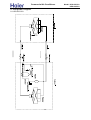
Commercial Air Conditioner
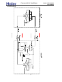
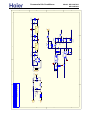
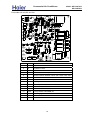
8. Refrigerant Diagram
8.1 HPU-42CV03
39
Model: HPU-42CV03
HPU-42HV03
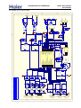
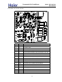
Commercial Air Conditioner
8.2 HPU-42HV03
40
Model: HPU-42CV03
HPU-42HV03
Commercial Air Conditioner
Model: HPU-42CV03
HPU-42HV03
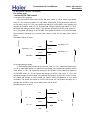
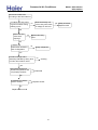
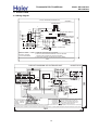
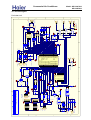
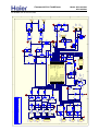
9. Electrical Control Functions
For indoor unit
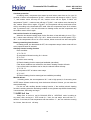
1.Indoor AUTO FAN control
A. During cooling program.
If the unit enters AUTO FAN for the first time, when Tr>Ts+2, select high speed;
when Tr≤Ts, select low speed; or it will select med speed; If the present fan speed is
AUTO HIGH, when Tr<Ts+2, fan speed will change to AUTO MED. If the present fan
speed is AUTO MED, when Tr<Ts, fan speed will change to AUTO LOW; when Tr>Ts+3,
fan speed will change to AUTO HIGH. If the present fan speed is AUTO LOW, when Tr>
Ts+1, fan speed will chenge to AUTO MED. Fan speed conversion in AUTO FAN mode:
the conversion will delay for 3 minutes from HIGH to LOW, and no delay from LOW to
HIGH.
The sketch map is as follow:
Temp.reduce
high
Set temp.+3℃
high
med
Set temp.+2℃
Set temp.+1℃
med
Temp. rise
low
Set temp.
low
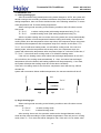
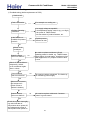
B. During heating program.
If the unit enters AUTO FAN for the first time, when Tr>Ts-1, select low speed; when
Tr≤Ts-3, select high speed; or it will select med speed; If the present fan speed is AUTO
LOW, when Tr<Ts-1, fan speed will change to AUTO MED. If the present fan speed is
AUTO MED, when Tr>Ts, fan speed will change to AUTO LOW; when Tr<Ts-3, fan
speed will change to AUTO HIGH. If the present fan speed is AUTO HIGH, when Tr>Ts-2,
fan speed will chenge to AUTO MED (Ts means setting temperature on the wired
controller). Fan speed conversion in AUTO FAN mode: the conversion will delay for 3
minutes from HIGH to LOW, and no delay from LOW to HIGH.
The sketch map is as follow:
Temp.reduce
low
low
Ts
Ts-1℃
med
Ts-3℃
high
high
41
Temp. rise
Ts-2℃
med
Commercial Air Conditioner
Model: HPU-42CV03
HPU-42HV03
2. Automatic run
1). Cooling-heating type
After the machine being started and running mode changes to AUTO, the system will
decide running mode according to difference between the present room temperature and
setting temperature, then runs as the decided mode. In the following selections, Tr means
room temperature and Ts means setting temperature.
Select running mode according to the following conditions at the first time to enter
Auto mode:
Tr≥Ts-3℃
to select cooling mode (with setting temperature being Ts +3)
Tr<Ts-3℃
to select heating mode (with setting temperature being Ts)
After the system entering auto run mode, the running mode can convert automatically
according to variation of room temperature between cooling and heating. If the unit is in
cooling mode, when the temperature arrives stop value, the compressor stops; the system
will measure the temperature after compressor stops for 3 minutes. At this time, if Tr<
Ts-3℃, the unit will enter heating mode, or it will still be cooling mode. If the unit is in
heating mode, when the temperature arrives stop value, the compressor stops; the
system will measure the temperature after compressor stops for 3 minutes. At this time, if
Tr<Ts+3℃, the unit will enter cooling mode, or it will still be heating mode.
If the unit is in heating mode, when indoor heat exchanger temperature is over 63℃,
the unit will turn into cooling mode automatically, in 1 hour, the indoor heat exchanger
temperature will not be limited, and heating operation will stop temporarily, 1 hour later,
the system will adjust the working mode due to the above conditions.
If the unit is in heating mode for the first time, compressor motor will start up, within 8
minutes the
system will not measure indoor ambient temperature, the remote controller will be off.
Temp.reduce
low
Ts+3℃
low
Ts-3℃
Ts-3℃
high
high
Temp. rise
ventilation
2). Single Cooling type
Select running mode according to the following conditions at the first time to enter
Auto mode:
Tr≥Ts+3℃
to select cooling mode
Tr<Ts-3℃
to select blowing mode
After entering Auto mode, the operation mode can be changed between cooling
mode and fan mode according to indoor ambient temperature: if the unit now is in cooling
mode, when Tr<Ts-3, the mode will be changed to Fan; if the unit is in Fan mode, when
42
Commercial Air Conditioner
Model: HPU-42CV03
HPU-42HV03
Tr≥Ts+3, the mode will be changed to cooling mode.
Temp.reduce
cool
Ts+3℃
Ts-3℃
Temp. rise
cool
ventilation
ventilation
3. COOL mode control
4-way valve being powered off, compressor run/stop will depends on the temperature
difference between the room temperature and the set temperature.
Tr≥Ts+1
compressor will run;
Tr≤Ts-1
compressor will stop;
Ts-1<Tr<Ts+1 compressor will stay in original state
Temp.reduce
Compressor running
Ts+1
Ts-1
Temp. rise
Compressor stop
Anti-freezed protection
When the unit has run for over 6 minutes after compressor starts up, if indoor coil
temperature Tg<1℃ last 1 minute, the compressor and the outdoor motor will stop; 9
minutes later after compressor stops and when indoor coil temperature rises to 10℃, the
compressor and the outdoor motor will run again.
Current peak value protection
Controlled by outdoor unit.
4. DRY mode control (in the following selections, Tr means room temperature and Ts means
setting temperature.)
When the uint enters DRY mode for the first time, the compressor, outdoor motor and
indoor motor will perform according to the below conditions:
Tr> Ts+2℃ the compressor and the outdoor motor will run continuously, indoor
motor will run at the set speed, this area is defined as Area A;
Ts≤Tr≤Ts+2℃, the compressor and the outdoor motor will always run for 10
minutes and then stop for 6 minutes, indoor motor will be LOW speed, this area is defined
as Area B;
Tr < Ts, the compressor and the outdoor motor will stop, indoor motor will run at Low
speed, this area is defined as Area C.
After the unit is running in DRY mode, the system will change over among Area A,
Area B, and Area C. If the system is in Area A, when Tr<Ts+2, change to Area B; If the
43
Commercial Air Conditioner
Model: HPU-42CV03
HPU-42HV03
system is in Area C, when Tr > Ts, change to Area B; If the system is in Area B, when Tr>
Ts+3, change to Area A; When Tr<Ts-1, change to Area C.
Temp.reduce
Area A
Area A
Ts+1
Ts+3
Ts-1
Area C
Temp. rise
Area B
Area B
Ts
Area C
Anti-freezed protection: When the unit has run for over 6 minutes after compressor
starts up, if indoor coil temperature Tg<1℃ last 1 minute, the compressor and the outdoor
motor will stop; 9 minutes later after compressor stops and when indoor coil temperature
rises to 10℃, the compressor and the outdoor motor will run again.
5. Fan mode control
Compressor and outdoor motor stop working, indoor motor can set High, Med and Low
speed, the fan blade can swing or be fixed on a position. In this mode, you can set TIMER
function, but there is no SLEEP function. Also, you can set high voltage dirt collecting or
fresh air function.
6. HEAT mode control
(in the following selections, Tr means room temperature and Ts means
setting temperature.)
4-way valve control: When entering heating mode for the first time, compressor starts
up, 4-way valve will be on 3 minutes later; in heating mode, 4-way valve will not be off. If
the unit changes from heating to other modes, 4-way valve will be off immediately.
compressor control: the compressor and outdoor fan motor will depends on the
temperature difference between the room temperature and the set temperature.
Tr≥Ts + 1
compressor stops
Tr≤Ts- 1
compressor running
Ts-1<Tr<Ts + 1 compressor retains original state
Temp.reduce
Compressor stop
Ts+1
Temp. rise
Ts-1
Compressor running
Outdoor motor and the compressor runs or stops simultaneously (except for
overheat protection), indoor fan speed can be set at High, Med, Low or Auto speed, and
44
Commercial Air Conditioner
Model: HPU-42CV03
HPU-42HV03
the fan blade can swing or be fixed on one position. You can set TIMER or SLEEP mode.
Overheat protection
In heating mode, compressor has started up and indoor motor has run for over 30
seconds, if indoor coil temperature Tg>56℃, outdoor motor will chenge to LOW; if Tg<52
℃, and outdoor motor has stop for 45s, outdoor motor will run again; if indoor coil
temperature Tg>60℃, outdoor motor will stop; if Tg<56℃, and outdoor motor has stop for
45s, outdoor motor will run again; if Tg>68℃, the compressor will stop and indoor motor
will run according to the thermostat OFF state. After the compressor stops for 9 minutes
and Tg reduces to 48℃, the unit will resume to heating mode, and the compressor and
the outdoor motor will run again.
Anti-cold air function in heating mode
When the uint enters heating mode for the first time, or last defrosting is over, if Tg<
28℃, indoor motor will stop; if 38℃>Tg≥28℃, indoor motor will run at low speed; if Tg≥
38℃ or the compressor has run for over 4 minutes, indoor motor will run at the set speed.
Blowing remaining heat function
In heating mode, the thermostat is OFF, the compressor stops, indoor motor will run
at low speed at least 50 seconds.
Auxiliary electric heating function
Enter condition:
1) Tr≤Ts-2℃
2) compressor ON and running for 1 minute
3) Tr≤23℃
4) Indoor motor running
5) Electric heating function start signal available (cancelled)
If the above conditions can all be met, the electric heating function will work.
If one of the below conditions can be met, the electric heater will stop:
1) Tr≥Ts-1℃
2) compressor OFF or indoor motor stops
3) Tr≥25℃
4) Electric heating function start signal not available (cancelled)
Manual defrost:
In heating mode, the set temperature 30℃ and in high speed, in 5 seconds, press
SLEEP button 6 times continuously, then the buzzer will sound 3 times, you can enter the
manual defrosting.
For the unit with auxiliary electric heating function, If the auxiliary electric heating
function is working when the defrosting condition is met, please stop electric heater firstly,
3 seconds later, defrosting can begin.
7. SLEEP function
Sleep function can be setted in COOLING, DRY and HEATING mode. in cooling or
dry mode, after running at SLEEP mode for 1 hour, the set temperature will rise 1℃,
another 1 hour later, the set temperature will rise another 1℃; the unit continues running
for 6 hours, then the unit will stop.
45
Commercial Air Conditioner
Model: HPU-42CV03
HPU-42HV03
Setting temperture
Ts+2
Ts+1
Ts
SLEEP time
1
2
8
In heating mode, after running at SLEEP mode for 1 hour, the set temperature
reduces 2℃, another 1 hour later, the set temperature will reduce 2℃, and another 3
hours later, the set temperature rises 1℃; the unit continues running for 3 hours, then the
unit will stop.
Setting temperture
Ts
Ts-2
Ts-3
Ts-4
1
8. Compulsory cooling operation
SLEEP time
2
5
8
After the panel receives the compulsory cooling signal, the unit enters the compulsory
cooling state. and indoor/outdoor motors are in high speed; in the 5 minutes, the system
will not adjust the protection and not be limited by the ambient temperature, but the
compressor will be limited by 3-minute protection. 5 minutes later, the unit will enter the
normal cooling state.
9. System protection
9.1 3-minute protection for compressor startup
After the compressor stops, at least 3 minutes later, the compressor can restart up; if
the unit is powered off in running less than 3 minutes, after being electrified, 3 minutes
later, the compressor can restart up. Being electrifed for the first time, there is no 3-minute
delay protection.
9.2 Sensor failure protection
9.3 Communication failure protection
10. Panel selection
Select the panel according to the 2 dip switch
Style of panel
Cabinet V panel
Cabinet Z panel
Wired controller
1
OFF
ON
ON
2
ON
OFF
ON
46
Commercial Air Conditioner
Model: HPU-42CV03
HPU-42HV03
10. Diagnostic information (troubleshooting)
10.1 Failure code
10.1.1 For outdoor units
Fault code
Failure description
Outdoor ambient temp. sensor failure
E3 / flash 3 times
Outdoor coil temp. sensor failure
E4/ flash 4 times
Fault in discharging temp. sensor
E4/ flash 4 times
Phase failure
E5/ flash 5 times
Compressor current protection
E5/ flash 5 times
High pressure abnormal
E6/ flash 6 times
Low pressure malfunction
E6/ flash 6 times
Communication failure
E9/ flash 9 times
10.1.2 For indoor unit
No.
Operation
Fault description
panel display
1
Indoor ambient temp. sensor failure
E1
2
Indoor coil temp. sensor failure
E2
3
Outdoor ambient temp. sensor failure
E3
4
Outdoor coil temp. sensor failure
E4
5
CT current failure
E5
6
Pressure protection
E6
7
8
Communication
failure
between
indoor
units panel
Communication failure between indoor and
outdoor PCB
47
E8
E9
Commercial Air Conditioner
Model: HPU-42CV03
HPU-42HV03
10.2 Troubleshooting
1) Troubleshooting (before replacement of PCB)
Service call
Fault confirmation
For example: no cooling, etc.
Confirm operating
conditions
1.Is supply voltage acceptable?
2.Is temperature setting correct? (e.g. too high)
3.Is system in TIMER mode?
4.Is user aware of product features, etc.
Is the feature not
available for present
product?
yes
Explain product
features to user
no
Switch on air
conditioner
Does the same
fault occur before?
No need to replace mainboard. (Check
operating status in details, e.g. TIMER feature,
supply failure, thunder storm, interference from
other appliances, etc.) Explain causes of fault
to user.
no
yes
Switch off air conditioner
temporarily. Switch
on air conditioner again
after 1 minute
yes
Does the same
fault occur before?
no
No need to replace mainboard. The fault may
be caused by power supply
no
No need to replace mainboard. Contactor
wasn't in good contact
yes
Disconnect contactor
and reconnect it.
(check if fuse or
varistor is broken.)
no
Does the same
fault occur before?
yes
Check the system thoroughly,
e.g. technical data of
components when power-off,
and voltage and current of
check points when power-on
48
Commercial Air Conditioner
2) Sensor failure
check if the wiring is
correct according to
wiring diagram
if sensor is fixed
well
no
reconnect
no
Relocate
yes
yes
Is sensor short-circuit
or open-circuit?
Replace sensor
yes
no
Is sensor resistance
acceptable?
Replace sensor
yes
Is DC voltage between
both ends of sensor
near 5V or 0V?
no
Replace PCB
3) EEPROM failure
start
Is EEPROM in mainboard
inversely connected or in
poor contact?
replace EEPROM
no
no
re-set
replace PCB
Power on again to
check if failure is
eliminated
49
Model: HPU-42CV03
HPU-42HV03
Commercial Air Conditioner
Model: HPU-42CV03
HPU-42HV03
4) Communication error between indoor and outdoor units
Confirm commumication failure
according to the fault code list
Confirm the fault indicator is
communication failure
yes
Does indoor communication
indicator flash?
Are communication wire
P, Q connected contrarily
and supply wires L and N
properly connected?
no
no
re-wiring
yes
check the other
reasons
yes
Is communication wire too
no close to power cable, which
causes interference?
yes
if communication wire
is broken
yes
re-wiring
no
S should not share
a multicore cable
with L and N
check if indoor/outdoor PCB fuse
and transformer are normal
no
change
defective parts
yes
replace indoor PCB
if failure is eliminated
5) Phase loss or phase failure
confirm the malfunction
according to the fault code list
Check if the phase detecting
circuit is correct according to
ourdoor wiring diagram
no
if the failure disappear
after correcting the
wiring
yes
no
Is there phase loss
or phase failure?
no
adjust power
supply
no
Is fault corrected after
sequence of either two of three
RST phases is adjusted?
no
replace outdoor
PCB
50
no
replace outdoor PCB
Commercial Air Conditioner
Model: HPU-42CV03
HPU-42HV03
6) Temperature cutoff protection
confirm the malfunction
according to the fault code list
Is outdoor four-way valve
in good condition during
heating cycle?
Does small relay coil
of four-way valve have
a voltage of 12V DC?
no
yes
Does four-way
valve work
properly?
no
Replace four-way
valve
yes
Is indoor unit
malfunction caused by
lack of refrigerant?
no
charge refrigerant
yes
Is heat exchange effect
adversely affected by heavy dust
in indoor and outdoor units?
no
cleaning
yes
Are indoor sensors for
ambient temperature and
coil properly located?
no
Relocate
yes
Is resistance of indoor
sensor correct?
no
Replace sensor
yes
Replace indoor PCB
51
yes Relay is broken.
Replace PCB
Commercial Air Conditioner
7) Pressure protection
Confirm the fault according
to the fault code list
Does system have
pressure switch?
no
Are CN17 and CN18
in PCB cut off?
no
yes
yes
Make them in
short circuit
Is actual pressure detected by
pressure gage acceptable?
no
low pressure failure
yes
Is high pressure too low?
yes
Refrigerant charge is
needed. Check if there is
refrigerant leak. If yes,
replace pipe.
no
yes
Change pressure
switch
high pressure failure
yes
no
is pipe blocked?
yes
dredge piping
52
Replace PCB
Model: HPU-42CV03
HPU-42HV03
Commercial Air Conditioner
Model: HPU-42CV03
HPU-42HV03
11. Electric data
11.1 Wiring diagram
CIRCUIT DIAGRAM OF INDOOR UNIT
0010578081
TRANSFORMER
%
5
CN5
CN4
3
)86(
CN3
CN23
ROOM TEMP SENSOR
BM1 BM2
CN7
PIPING TEMP SENSOR
CONTROL PANEL
BM3 BM4
CN22 CN11 CN12 CN13
ONE-OFF FUSE
CN6
T3.15A/250VAC
CN25
1 2
:
CN24
CN2
CN10
SWING MOTOR
SWING MOTOR
RESUMABLE PROTECTOR
CAPACITOR
M
Y/G
FAN MOTOR
M
M
R BL Y B
HEATER
90
TO OUTDOOR UNIT
Y/G
REMOTE CONTROLLER
B:BLACK R:RED
NOTE˖1ǃREMOTE CONTROLLER IS OPTIONAL .
2ǃREFER TO OPERATION INDOOR MANUL TO SET DIP BM1-BM4 .
PLEASE DO NOT CHANGE THE DIP SWITCH RANDOM.
Y/G:YELLOW/GREEN
3ǃNO ELECTRIC HEATING TYPE WITHOUT ELECTRIC HEATER.
W:WHITE BL:BLUE
120
0010573510
CIRCUIT DIAGRAM OF OUTDOOR UNIT
7
8
TRANS.
6
BL B R
CN1
CN2
5
CN10
LOW PRESSURE SWITCH
2
OUTDOOR AMBIENT SENSOR
OUTDOOR PIPING SENSOR
COMPRESSOR VENT SENSOR
R
BL
B
W
R
CT
CN3
5P 10P
CN12
SW1
BL
CN5
3
S
L3
L2
FUSE
L1
N T3.15A/250VAC
4
FAN MOTOR
SPEED
CONTROLLER
FAN
MOTOR
Y/G
1
FAN
MOTOR
CAP
Y/G
FAN MOTOR
4-WAY
VALVE
SOLENOID
COMPRESSOR
R
W R
S
BL T
M
CN4
Y/G
4
B
2
GR
FAN
MOTOR
CAP
MAGNETIC CONTACTOR
CN7
B
Y/G:YELLOW/GREEN
R:RED
W:WHITE
BL:BLUE B:BLACK
GR:GRAY
1
W
CN9
CN11
3
HIGH PRESSURE SWITCH
5
COM NO NC
B
6
Y/G
CRANKCASE
HEATER
NOTE: 1. DASHED PART 1 IS NOT AVAILABLE IN COOLING CAPACITY BELOW 36000Btu
2. DASHED PARTS 2 3 ARE NOT AVAILABLE IN ONLY COOLING TYPE
R S T N1 2 3
3. DASHED PART 4 IS OPTIONAL FOR LOW AMBIENT TEMP. COOLING,
AND THERE IS NO FAN MOTOR SPEED CONTRLLER IN NORMAL TYPE
4. DASHED PARTS 5 6 ARE NOT AVAILABLE IN SOME TYPE
5. FOR COOLING CAPACITY IS 52000BTU AND 28000BTU TYPES,THE DIP SWITCH SW1 IS ON 5P SIDE,FOR COOLING CAPACITY IS 42000BTU AND 36000BTU TYPES,THE DIP SWITCH SW1 IS ON 10P SIDE.
6. FOR COOLING CAPACITY IS 52000BTU TYPE,THE LINE THROUGH CT IS ONE CIRCUIT,FOR COOLING CAPACITY IS 42000BTU 36000BTU AND 28000BTU TYPES,THE LINE THROUGH CT IS TWO CIRCUITS.
POWER SUPPLY TO INDOOR UNIT
53
1
0.033UF/120¦¸
RC2
N
+12
R12
RC
10K
+5
J14 0K
C17
104
10K
R3
10K
+5
2
1
2
3
4
5
6
7
8
9
10
11
12
13
14
15
16
17
18
19
20
21
IC1
CN20
1
1
187
CN19
N
L1
187 OXYGEN
+12
K1
42
41
40
39
38
37
36
35
34
33
32
31
30
29
28
27
26
25
24
23
22
3
A1
A2
A3
A4
A5
A6
A7
VCC
Q1
Q2
Q3
Q4
Q5
Q6
Q7
IC2 ULN2003
GND
+5
9013
N3
R36 10K
C19 R32 5.6K
104
R30 10K
R28 5.6K
R29 1K
C11
103
+5
10K
R33
892-1AC-12VDC
MC68HC908GT16CP
+5
E7
Á½Õë¶Ì·»·
XT
CD110 4.7uf/50V
VDDA
PTA7/KBD7
VSSA
PTA6/KBD6
PTE2
PTA5/KBD5
PTE3/OSC2 PTA4/KBD4
PTE4/OSC1 PTA3/KBD3
RST
PTA2/KBD2
PTC0
PTA1/KBD1
PTC1
PTA0/KBD0
PTC2
Vrefl(ADC)
PTC3
Vrefh(ADC)
PTC4
PTB7/AD7
PTE0/TXD
PTB6/AD6
PTE1/RXD
PTB5/AD5
IRQ
PTB4/AD4
PTD0/SS
PTB3/AD3
PTD1/MISO PTB2/AD2
PTD2/MOSI PTB1/AD1
PTD3/SPSCK PTB0/AD0
Vss
PTD7/T2CH1
Vdd
PTD6/T2CH0
PTD4/T1CH0PTD5/T1CH1
R24 10K
C16
104
R23 10K
1
2
1
2
CHECK
Á½Õë¶Ì·»·
+12
104
+5 C7
BM4
+5
R44
5.6K
R25
1K
R17
5.6K
C24
103
IC4
+5
R14
N1
9013
R37 20K*
红色
CN10
COM
GND
+12V
1N4007
4
D6
1N4007
103
D5
104
E4
TLP371
+5
+5
E5
N
BM3
BM2
R42 33K
C23
R41 2.2K
C22
1
2
3
4
5
6
8A1206
RB1
1
2
3
4
5
6
RB2
IC5
R40 20K*
TLP521
C21
1K
C8 R39
102
R38 1K
C20
104
+12
1
2
3
4
B4B-XH-A 8A1206
面板通讯接口
104
C9
102
560¦¸
R26 3K
R11 10K
R15 10K
R16 5.6K
103
C6
R27 10K
N4
9013
4
ÐÍ ºÅ
רÓúÅ
°æ±¾ºÅ A
º£¶û¼¯ÍÅÑз¢Íƽø±¾²¿¿Æ¼¼ÓÐÏÞ¹«Ë¾
Éè ¼Æ
Éó ºË
Åú ×¼
CN25
外机通讯接口
1
187
R34
LED
Φ3 红色散光
PIPE
ROOM
KFR-120LW
0010452322
µÚ1Ò³ ¹²2Ò³
+5
B4B-XH-A
4
3
2
1
CN7
R31
RJ15 0.5W/10K
1
L1
K6
K7
OSC
C12
R7
10K
104
R8
E6
8MHz
CST8MGW 1M
GND DI
A
DE
B
RE
Vcc RO
IC3 MAX487
BM1
RLS4148
D7
R13 10K
K8
892-1CC-12V
892-1AC-12VDC 892-1CC-12V
CN22
250
CN11 250
1
LOW
CN12 250
1
MED
1
10K
10K
R5
10K
R4
R6
+5
R22 1K
R21 1K
R9
+5
R10 10K
C14
10K
103 R20
3
RJ15 0.5W/10K
1
CN13 250
HI
+5
´ÉÖé103
DL2
´ÉÖé103
远程通讯接口
DL1
CN2
1
2
B2B-XH-R
红色
C18
104
C13
103
2
CD110 4.7uf/50V
CD110 4.7uf/50V
D
C
B
A
1
CD110 4.7uf/50V
Model: HPU-42CV03
HPU-42HV03
Commercial Air Conditioner
11.2 Circuit diagram
For indoor unit
D
C
B
A
N
1
R27
10K
+5
红色
CN8
3
2
1
+5
C27
103
R50
1K
R28
5.6K
R29
4.7K
R30
4.7K
C10
103
R62
10K
SW1
MK-12D13-G2
R55 10K
C5
103
R53
10K
+5
R31
5.6K
+5
R45 1K
R44 1K
R17
10K
TLP521
TLP521
´®ÐÐͨѶ
B3B-XH
R49
P1
9012
C14
104
2K
10K
IC7
IC6
R46
µÍѹ±£»¤
白色
2
1
2
1
红色
¸ßѹ±£»¤
CN2
VHB2B
+5
CN10
VHB2B
R48
2K
R47
10K
R34
33K/2W
D6
IN4007
R35
33K/2W
R32
33K/2W
D7
IN4007
R61
10K
LED
OSC
2
5
6
7
8
C13
104
N7
9013
IC5
SDA
SCL
WP
VCC
+5
24C01A
+5
R43
10K
C29 +5
104
R58
1K
R57
1K
C9
103
C15
103
R23 560
rev
CSA8.00MG
R59 10K
R60 10K
N8
9013
C18
104
C19
104
GND
A2
A1
A0
R56
4
3
2
1
µçÁ÷¼ì²â
CT1
0057W
R18
10k
TEST Ç¿ÖÆÖÆÈÈ
Ç¿ÖÆÖÆÀä
R19
4.7K
C12
104
D13
28
27
26
25
24
23
22
21
20
19
18
17
16
15
D12
R20 1K
VSS
P37(AIN5/STOP5)
CLK/XIN
P36(AIN4/STOP4)
XOUT
P35(AIN3/STOP3)
VPP/TEST
P34(AIN2/STOP2)
VCC/VDD
P33)AIN1)
(XTIN)P21
P32(AIN0)
(XTOUT)P22 P31(TC4/PD04/PWM4/PPG4)
RESET
P30(TC3/PDO3/PWM3)
(STOP/INT5)P20
P12(DVO)
(TXD)P00
P11((INT1)
(TXD)P01
P10(INT0)
(SCLK)P02
P07(TC1/INT4)
(MOSI)P03
P06(INT3/PPG)
(MISO)P04
P05(SS)
IC4 TMP86P807N
R51
10K
5.1K
1
2
3
4
5
6
7
8
9
10
11
12
13
14
3
3
D15
D14
R13
470
R10
1k
E4
+5
470UF/16V
VR
101
R22
5.6K
R40
5.6K
R38 5.6K
R37
5.6K
D21
4148
R11
1k
N6
9013
Éè ¼Æ
Éó ºË
Åú ×¼
D18
D19
IN4007
D20
IN4007
D16
IN4007
R39
1K
C25
104
R41
1K
C20
104
R42
1K
C11
104
+12
R24
5.1K
R25
5.1K
R26
47K
K6
K7
K3
K5
4
4
4.7UF/16V
E7
E6
4.7UF/16V
L
+5
白色
B2B-XH
CN3
1
2
HJWD
Íâ»·¾³Î¶È
红色
CN12
1
2
B2B-XH
PGWD
ÍâÅ̹ÜζÈ
蓝色
CN11
1
2
L
H
N
B2B-XH
YJTQ
ѹ»úÍÂÆøζÈ
N
CN9
1
2
3
4
5
蓝色
Íâ·ç»ú
B3P5-VH
CN7
1
2
白色
ѹËõ»ú1
B2P3-VH
CN5
1
2
ËÄͨ·§
B2P3-VH
KFR-120LW/K
0010452378
µÚ1Ò³ ¹²2Ò³
E5
4.7UF/16V
ÐÍ ºÅ
רÓúÅ
°æ±¾ºÅ A
º£¶û¼¯ÍÅÑз¢Íƽø±¾²¿¿Æ¼¼ÓÐÏÞ¹«Ë¾
C6
104
9013
N5
9013
N4
9013
N2
IN4007
D
1
L2
250
L3
1
250
R33
33K/2W
2
892-1CC-C
892-1AC-C
892-1AC-C
892-1AC-C
C
B
A
1
sent
Model: HPU-42CV03
HPU-42HV03
Commercial Air Conditioner
For outdoor unit of HPU-42CV03
D
C
B
A
D
+5
E2
100UF/16V
1
3
C7
104
7805
Vout
S
1
250
N
L1
Vin
1
E3
D1
4007
Vout
7812
2
D3
4007
10K/0.5W
R16
10K/0.5W
R15
R3
62K/3W
R2
62K/3W
D2
4007
22uF/250V
E8
R1 200K
C31
104
3
R4
62K/3W
+12
D4
4007
470UF/25V
2
GND
2
C
B
A
1
GND
2
Model: HPU-42CV03
HPU-42HV03
Commercial Air Conditioner
R5
33K
C2
103
Vin
1
TLP371
103
C3
IC1
IC2
E1
R6
2.2K
C8
104
+5
TLP521
D9
D8
2200UF/35V
R12
560 +5
R7
10K
D10
D11
R8
1K
3
C4
103
CN1
1
2
3
B3B-XH
白色
3
CN4
2
1
sent
rev
RTB-1.5-2P
C23
0.1Uf-275VAC
LX
LX102
C24
0.1Uf-275VAC
FUSE
4
T3.15A/250V
RV
S14K350
4
ÐÍ ºÅ
רÓúÅ
°æ±¾ºÅ A
º£¶û¼¯ÍÅÑз¢Íƽø±¾²¿¿Æ¼¼ÓÐÏÞ¹«Ë¾
Éè ¼Æ
Éó ºË
Åú ×¼
1
L1
250
1
N
250
KFR-120LW/K
0010452378
µÚ2Ò³ ¹²2Ò³
D
C
B
A
N
红色
¸ßѹ±£»¤
CN2 2
B2B-VH 1
+5
1
R27
10K
+5
红色
CN8
3
2
1
+5
1K
R50
C27
103
R53
10K
C5
103
R55 10K
R28
5.6K
R29
4.7K
R30
C19
104
C18
104
9013
N8
OSC
2
5
6
7
8
C13
104
N7
9013
IC5
SDA
SCL
WP
VCC
+5
24C01A
+5
R43
10K
C29 +5
104
R58
1K
R57
1K
C9
103
C15
103
R23 560
rev
CSA8.00MG
R60 10K
LED
R59 10K
¦µ3(É¢¹âºìÉ«)
C10
103
R62
10K
SW1
+5
MK-12D13-G2
R31
5.6K
+5
R45 2K
R44 2K
R17
10K
TLP521
TLP521
´®ÐÐͨѶ
B3B-XH
R49
P1
9012
C14
104
1K
10K
IC7
IC6
R46
µÍѹ±£»¤
白色
CN10 2
B2B-VH 1
R48
2K
R47
10K
R34
33K/2W
D6
IN4007
R35
33K/2W
R32
4.7K
R61
10K
GND
A2
A1
A0
R56
4
3
2
1
TJC8-03A
TEST
µçÁ÷¼ì²â
CT1
0057W
R18
10k
Ç¿ÖÆÖÆÈÈ
Ç¿ÖÆÖÆÀä
R19
4.7K
C12
104
D13
28
27
26
25
24
23
22
21
20
19
18
17
16
15
D12
R20 1K
VSS
P37(AIN5/STOP5)
CLK/XIN
P36(AIN4/STOP4)
XOUT
P35(AIN3/STOP3)
VPP/TEST
P34(AIN2/STOP2)
VCC/VDD
P33)AIN1)
(XTIN)P21
P32(AIN0)
(XTOUT)P22 P31(TC4/PD04/PWM4/PPG4)
RESET
P30(TC3/PDO3/PWM3)
(STOP/INT5)P20
P12(DVO)
(TXD)P00
P11((INT1)
(TXD)P01
P10(INT0)
(SCLK)P02
P07(TC1/INT4)
(MOSI)P03
P06(INT3/PPG)
(MISO)P04
P05(SS)
IC4 TMP86P807N
R51
10K
5.1K
1
2
3
4
5
6
7
8
9
10
11
12
13
14
3
3
D15
D14
R13
470
R10
1k
E4
+5
470UF/16V
VR
101
R22
5.6K
R40
5.6K
R38 5.6K
R37
5.6K
D21
Éè ¼Æ
Éó ºË
Åú ×¼
D18
D19
IN4007
D20
IN4007
D16
IN4007
R39
1K
C25
104
R41
1K
C20
104
R42
1K
C11
104
+12
R24
5.1K
R25
5.1K
R26
47K
K6
4
4.7UF/16V
E7
4.7UF/16V
E6
+5
白色
B2B-XH
CN3
1
2
HJWD
Íâ»·¾³Î¶È
红色
CN12
1
2
PGWD
ÍâÅ̹ÜζÈ
B2B-XH
蓝色
CN11
1
2
L
H
N
B2B-XH
YJTQ
ѹ»úÍÂÆøζÈ
N
CN9
1
2
3
4
5
蓝色
Íâ·ç»ú
B3P5-VH
CN7
1
2
白色
ѹËõ»ú1
B2P3-VH
CN5
1
2
ËÄͨ·§
B2P3-VH
AU42NAIBEA
0010452441
µÚ1Ò³ ¹²2Ò³
E5
4.7UF/16V
L
K3
K7
K5
4
ÐÍ ºÅ
רÓúÅ
°æ±¾ºÅ A
º£¶û¼¯ÍÅÑз¢Íƽø±¾²¿¿Æ¼¼ÓÐÏÞ¹«Ë¾
C6
104
1N4148
R11
1k
N6
9013
9013
N5
9013
N4
9013
N2
IN4007
D
1
L2
250
L3
1
250
33K/2W
D7
IN4007
R33
33K/2W
2
892-1CC-C
892-1AC-C
892-1AC-C
892-1AC-C
C
B
A
1
sent
Model: HPU-42CV03
HPU-42HV03
Commercial Air Conditioner
For outdoor unit of HPU-42HV03
D
C
B
A
D
+5
E2
100UF/16V
1
3
C7
104
7805
Vout
S
1
250
N
L1
Vin
1
D1
Vout
7812
2
D3
10K/0.5W
R16
10K/0.5W
R15
1N4007
R3
62K/3W
R2
62K/3W
D2
1N4007
22uF/250V
E8
R1 200K
C31
104
3
R4
62K/3W
+12
D4
1N4007
1N4007
E3
470UF/25V
2
GND
2
C
B
A
1
GND
2
Model: HPU-42CV03
1
HPU-42HV03
Commercial Air Conditioner
R5
33K
C2
104
Vin
1
TLP371
103
C3
IC1
IC2
E1
R6
2.2K
C8
104
+5
TLP521
D9
D8
2200UF/35V
R12
560 +5
R7
10K
D10
D11
R8
1K
3
C4
103
CN1
1
2
3
B3B-XH
白色
3
2
1
CN4
sent
rev
RTB-1.5-2P
C23
0.1Uf/275VAC
LX
LX102
C24
0.1Uf/275VAC
FUSE
4
T3.15A/250V
RV
S14K350
4
ÐÍ ºÅ
רÓúÅ
°æ±¾ºÅ A
º£¶û¼¯ÍÅÑз¢Íƽø±¾²¿¿Æ¼¼ÓÐÏÞ¹«Ë¾
Éè ¼Æ
Éó ºË
Åú ×¼
1
L1
250
1
N
250
AU42NAIBEA
0010452441
µÚ2Ò³ ¹²2Ò³
D
C
B
A
Commercial Air Conditioner
Model: HPU-42CV03
HPU-42HV03
11.3 Printed diagram
For indoor unit
No.
Port
Function
1
Fuse
T3.15A 250VAC
2
CN2
Central controller B2B-XH-R
3
CN3
Live wire (L)-250
4
CN4
Neutral wire (N)-250
5
CN5
Primary side of transformer RTB-1.5-2P
6
CN6
Second side of transformer B3B-XH-A
7
CN7
Sensor B4B-XH-A
8
CN10
Operation panel B4B-XH-A
9
CN11
Low speed of fan motor -250
10
CN12
Middle speed of fan motor -250
11
CN13
High speed of fan motor -250
12
CN19
Negative ion generator (L)-187
13
CN20
Negative ion generator (N)-187
14
CN22
Neutral wireof fan motor-250
15
CN23
Electrical heater (L)-250
16
CN24
Electrical heater (N)-250
17
CN25
Communication between indoor and outdoor units -187
59
Commercial Air Conditioner
Model: HPU-42CV03
HPU-42HV03
For outdoor unit of HPU-42CV03
No.
Port
Function
1
L1
3-phase L1-250
2
L2
3-phase L1-250
3
L3
3-phase L1-250
4
N
Neutral wire of three phase N-250
5
S
Communication between indoor and outdoor units -250
6
CN1
Second side of transformer B3B-XH
7
CN2
High pressure switch B2B-VH
8
CN4
Primary side of transformer RTB-1.5-2P
9
CN7
Control port for AC contactor B2P3-VH
10
CN8
Connection port of outdoor device B3B-XH
11
CN9
Outdoor fan motor B3P5-VH
12
CN10
Low pressure switch B2B-VH
13
CN11
Discharging sensor B2B-XH
14
Fuse
T3.15A/250VAC
15
SW1
Dip switch
60
Commercial Air Conditioner
Model: HPU-42CV03
HPU-42HV03
For outdoor unit of HPU-42HV03
No.
Port
Function
1
L1
3-phase L1-250
2
L2
3-phase L1-250
3
L3
3-phase L1-250
4
N
Neutral wire of three phase N-250
5
S
Communication between indoor and outdoor units -250
6
CN1
Second side of transformer B3B-XH
7
CN2
High pressure switch B2B-VH
8
CN3
Outdoor ambient temp. sensor B2B-XH
9
CN4
Primary side of transformer RTB-1.5-2P
10
CN5
4-way valve B2P3-VH
11
CN7
Control port for AC contactor B2P3-VH
12
CN8
Connection port of outdoor device B3B-XH
13
CN9
Outdoor fan motor B3P5-VH
14
CN10
Low pressure switch B2B-VH
15
CN11
Discharging sensor B2B-XH
16
CN12
Outdoor defrost sensor B2B-XH
17
Fuse
T3.15A/250VAC
18
SW1
Dip switch
61
Commercial Air Conditioner
Model: HPU-42CV03
HPU-42HV03
11.4 Sensor characteristic
Model
HPU-42CV03(in)
HPU-42HV03(in)
HPU-42CV03(out)
HPU-42HV03(out)
Part code
Name
Characteristic
0010401922
indoor coil temp. sensor
R25=10KΩ±3%,
B25/50=3700K±3%
001A3900159
indoor ambient temp. sensor
R25=23KΩ±2.5%,
B25/50=4200K±3%
0010450398
discharging sensor
R80=50KΩ±3%,
B25/80=4450K±3%
0010450398
discharging sensor
R80=50KΩ±3%,
B25/80=4450K±3%
0010451314
outdoor coil temp. sensor
R25=5KΩ±1%,
B25/50=3450K±1%
001A3900110
outdoor ambient temp. sensor
R25=5KΩ±1%,
B25/50=3450K±1%
R25=10KΩ±3%
B25/50=3700K±3%
T(℃)
Rnom(KΩ)
T(℃)
Rnom(KΩ)
T(℃)
Rnom(KΩ)
T(℃)
Rnom(KΩ)
T(℃)
Rnom(KΩ)
-20
90.79
1
29.64
22
11.34
43
-19
85.72
2
28.22
23
10.87
44
4.93
64
2.38
4.9
65
2.3
-18
80.96
3
26.4
24
10.43
45
4.58
66
2.23
-17
76.51
4
25.61
25
-16
72.33
5
24.41
26
10
46
4.42
67
2.16
9.59
47
4.26
68
2.09
-15
68.41
6
23.27
27
9.21
48
4.11
69
2.03
-14
64.73
7
22.2
28
8.84
49
-13
61.27
8
21.18
29
8.48
50
3.97
70
1.96
3.83
71
1.9
-12
58.02
9
20.21
30
8.15
51
3.7
72
1.85
-11
54.97
10
19.3
31
7.83
52
3.57
73
1.79
-10
52.1
11
18.43
32
7.52
53
3.45
74
1.73
-9
49.4
12
17.61
33
7.23
54
3.33
75
1.68
-8
46.86
13
16.83
34
6.95
55
3.22
76
1.63
-7
44.46
14
16.09
35
6.68
56
3.11
77
1.58
-6
42.21
15
15.38
36
5.43
57
3.11
78
1.54
-5
40.08
16
14.71
37
5.6
58
2.9
79
1.49
-4
38.08
17
14.08
38
5.59
59
2.81
80
1.45
-3
36.19
18
13.48
39
5.73
60
2.72
-2
34.41
19
12.9
40
5.52
61
2.63
-1
32.73
20
12.36
41
5.32
62
2.54
0
31.14
21
11.84
42
5.12
63
2.49
62
Commercial Air Conditioner
R80=50KΩ±3%
B25/80=4450K±3%
R25=23KΩ±2.5%
B25/50=4200K±3%
T(℃)
Rnom(KΩ)
T(℃)
Model: HPU-42CV03
HPU-42HV03
Rnom(KΩ)
T(℃)
Rnom(KΩ) T(℃) Rnom(KΩ) T(℃) Rnom(KΩ)
-20℃
281.34
23℃
25.3
-30
11600
13
933.4
56
127.3
-19℃
263.56
24℃
24.12
-29
10860
14
886.4
57
122.1
-18℃
247.04
25℃
23
-28
10170
15
841.9
58
117.2
-17℃
231.66
26℃
21.94
-27
9529
16
800
59
112.5
-16℃
217.35
27℃
20.94
-26
8932
17
760.8
60
108
-15℃
204.02
28℃
19.99
-25
8375
18
722.8
61
103.8
-14℃
191.61
29℃
19.09
-24
7856
19
687.3
62
99.68
-13℃
180.04
30℃
18.23
-23
7372
20
653.8
-12℃
169.24
31℃
17.42
-22
6920
21
622
-11℃
159.17
32℃
16.65
-21
6498
22
592
-10℃
149.77
33℃
15.92
-20
6104
23
553.6
-9℃
140.99
34℃
15.22
-19
5736
24
536.6
-8℃
132.78
35℃
14.56
-18
5392
25
511.1
-7℃
125.11
36℃
13.93
-17
5071
26
486.9
-6℃
117.93
37℃
13.34
-16
4770
27
464
-5℃
111.22
38℃
12.77
-15
4488
28
442.3
-4℃
104.93
39℃
12.23
-14
4225
29
421.7
-3℃
99.04
40℃
11.71
-13
3978
30
402.1
-2℃
93.52
41℃
11.22
-12
3747
31
383.6
-1℃
88.35
42℃
10.76
-11
3531
32
366
0℃
83.5
43℃
10.31
-10
3328
33
349.3
1℃
78.94
44℃
9.89
-9
3138
34
333.5
2℃
74.67
45℃
9.49
-8
2960
35
318.4
3℃
70.65
46℃
9.1
-7
2793
36
304.1
4℃
66.88
47℃
8.74
-6
2636
37
290.5
5℃
63.33
48℃
8.39
-5
2489
38
277.6
6℃
60
49℃
8.05
-4
2351
39
265.3
7℃
56.86
50℃
7.73
-3
2221
40
253.6
8℃
53.91
51℃
7.43
-2
2099
41
242.5
9℃
51.13
52℃
7.14
-1
1984
42
232
10℃
48.51
53℃
6.86
0
1877
43
221.9
11℃
46.04
54℃
6.6
1
1775
44
212.3
12℃
43.72
55℃
6.34
2
1680
45
203.2
13℃
41.52
56℃
6.1
3
1590
46
194.5
14℃
39.45
57℃
5.87
4
1506
47
186.3
15℃
37.5
58℃
5.65
5
1426
48
178.4
16℃
35.66
59℃
5.44
6
1351
49
170.9
17℃
33.92
60℃
5.24
7
1280
50
163.7
18℃
32.27
8
1214
51
155.9
19℃
30.72
9
1151
52
150.4
20℃
29.25
10
1092
53
144.2
21℃
27.86
11
1036
54
138.3
22℃
26.54
12
983.2
55
132.7
63
Commercial Air Conditioner
R25=5KΩ±1%
B25/50=3450K±1%
T(℃)
Rnom(KΩ)
T(℃)
Rnom(KΩ)
T(℃)
Rnom(KΩ)
-20℃
47.12
10℃
10.35
40℃
2.633
-19℃
45.17
11℃
9.837
41℃
2.536
-18℃
43.24
12℃
9.351
42℃
2.432
-17℃
41.35
13℃
8.892
43℃
2.339
-16℃
39.49
14℃
8.458
44℃
2.25
-15℃
37.68
15℃
8.048
45℃
2.165
-14℃
35.92
16℃
7.661
46℃
2.084
-13℃
34.21
17℃
7.295
47℃
2.006
-12℃
32.56
18℃
6.949
48℃
1.932
-11℃
30.37
19℃
6.622
49℃
1.862
-10℃
29.44
20℃
6.313
50℃
1.793
-9℃
27.57
21℃
6.021
51℃
1.729
-8℃
26.57
22℃
5.744
52℃
1.667
-7℃
25.22
23℃
5.482
53℃
1.608
-6℃
23.94
24℃
5.235
54℃
1.551
-5℃
22.72
25℃
5
55℃
1.457
-4℃
21.55
26℃
4.778
56℃
1.445
-3℃
20.45
27℃
4.567
57℃
1.395
-2℃
19.39
28℃
4.36
58℃
1.347
-1℃
18.39
29℃
4.179
59℃
1.301
0℃
17.45
30℃
3.993
60℃
1.257
1℃
16.55
31℃
3.819
2℃
15.7
32℃
3.657
3℃
14.89
33℃
3.514
4℃
14.13
34℃
3.368
5℃
13.41
35℃
3.23
6℃
12.73
36℃
3.098
7℃
12.08
37℃
2.973
8℃
11.47
38℃
2.845
9℃
10.9
39℃
2.741
64
Model: HPU-42CV03
HPU-42HV03
Commercial Air Conditioner
Model: HPU-42CV03
HPU-42HV03
Sincere Forever
Haier Group
Haier Industrial Park, No.1, Haier Road
266101, Qingdao, China
http://www.haier.com