1
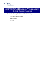
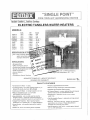
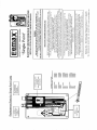
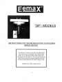
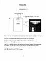
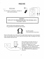
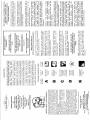
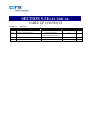
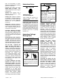
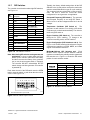
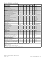
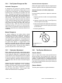
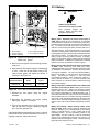
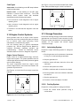
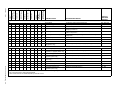
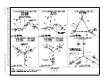
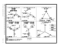
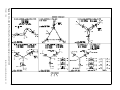
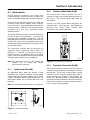
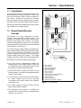
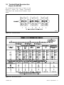
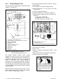
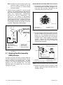
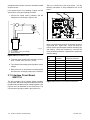
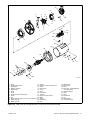
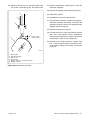
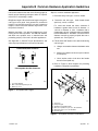
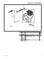
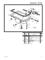
Primary and Secondary Emergency Venting
Manhole/Spillbox Combination for Filling, Dipping and Primary Tank Access.
Manhole/Spillbox has: Large 72 Litre Capacity, 3/4" Drain Back Port, 2" Dip
Port, Lockable Cover, Stainless Steel Hinge
Two 4" N.P.T. Couplings c/w M.I. Plugs
Containment Inspection Port
Approved Lift Lugs
Identification Name Plate
Structural Saddle Base Support
Grounding Lug
Gauge Stick and Dip Chart
Installation and Maintenance Manual
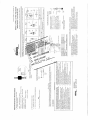
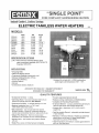
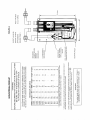
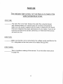
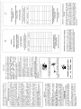
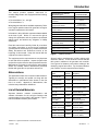
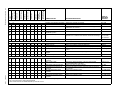
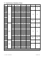
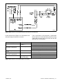
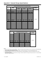
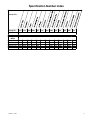
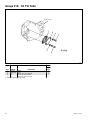
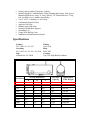
Specifications
Primary
ULC-S601-93 / UL-142
Secondary
ULC-S653-94 / UL-142 / UL-2044
Pipe
Schedule 40 A53 GR.B
Fittings
Class #150
Blast
SSPC-SP6
Coatings
Top Coat: High Build (Urethane)
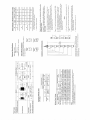
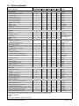
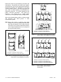
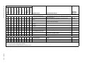
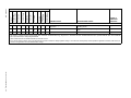
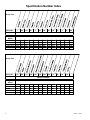
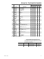
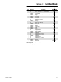
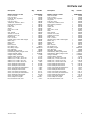
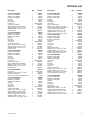
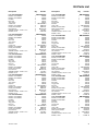
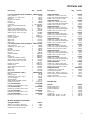
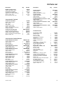
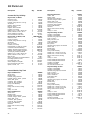
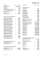
Overall Dimensions
Size (Liters)
H
W
L
95% Fill
Capacity
Approximate
Tank Weight
1,364
44"
39"
89"
1,296
674 lbs.
2,400
51"
60"
87"
2,280
1,453 lbs.
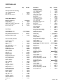
4,328
51"
64"
145"
4,112
2,100 lbs.
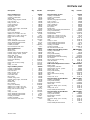
10,000
77"
66"
214"
9,500
5,200 lbs.
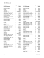
15,000
95"
81"
217"
14,250
7,400 lbs.
25,000
102"
90"
290"
23,750
10,100 lbs.
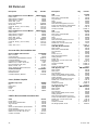
35,000
102"
90"
395"
33,250
12,900 lbs.
50,000
131"
119"
323"
47,500
20,400 lbs.
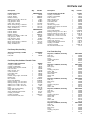
61,000
131"
119"
385"
57,950
23,700 lbs.
75,000
131"
119"
461"
71,250
27,600 lbs.
90,000
131"
119"
545"
85,500
33,000 lbs.
100,000
126"
138"
552"
95,000
32,318 lbs.
120,000
139"
151"
552"
114,000
40,522 lbs.
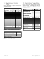
SECTION 9.1 HEATING, VENTILATION
& AIR CONDITIONING
Section 9.1 Heating, Ventilation & Air Conditioning
9.1.10 Fuel Tank Level Switch
Model # LS-800
Tag # NA
SECTION 9.1 HEATING, VENTILATION
& AIR CONDITIONING
Section 9.1 Heating, Ventilation & Air Conditioning
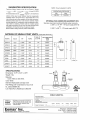
9.1.11 Eemax Tankless Water Heaters
Model # SP3208
Tag # NA
SECTION 9.1 HEATING, VENTILATION
& AIR CONDITIONING
Section 9.1 Heating, Ventilation & Air Conditioning
9.1.12 Fire Extinguisher
Model # WBDL-S20
Tag # NA
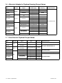
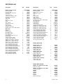
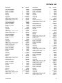
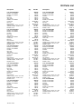
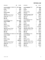
SECTION 9.2 ELECTRICAL
TABLE OF CONTENTS
Section 9.2
Section
Electrical
Manufacturer & Description
9.2.1
Kohler Standby Generator
9.2.2
Automatic Transfer Switches
Make/Model
Tag #
Kohler - 40REOZJB
Thomson Technology -
NA
TS873A0200A1BE3AKKAA
9.2.3
Protalk Alarm Reporting Unit
NA
9.2.4
UPS
NA
Page
SECTION 9.2 ELECTRICAL
Section 9.2 Electrical
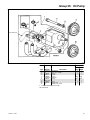
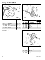
9.2.1 Kohler Standby Generator
Model # 40REOZJB
Tag # na
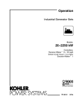
Operation
lndustrial Generator Sets
Models:
20-2250 kW
Controllers:
Decision-Maker* 3+, 1$-Light
Software (Code) Version 1 .10 or higher
Decision-Maker*
1
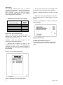
SI-IOP DRAWING REVIEW
üËËäiñìiì
ÀsiútrEo
eyi conns
oROErAl$,
Subrflission
I!
SEtUUMMtrNrù
r
Rcsueulr
lruenot
.Þ.-'
lirerecreo
J
Dl
Frolad No.
I
---G{
Æ
I
I
LLo N coNSU url
N
qLltïIED
a900-l
(/)ø¡+ER.
r
P()NERSSIEMS
NATIONATI,Y REGISTERED
l(oHtER..
PO\VERSYSTEMS
TP-6161 1/08f
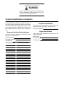
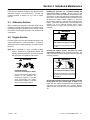
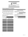
California Proposition 65
WARNING
Engine exhaust from this product contains chemicals
known to the State of California to cause cancer, birth
defects, or other reproductive harm.
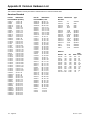
Product Identification Information
Product identification numbers determine service parts.
Record the product identification numbers in the spaces
below immediately after unpacking the products so that
the numbers are readily available for future reference.
Record field-installed kit numbers after installing the
kits.
Generator Set Identification Numbers
Record the product identification numbers from the
generator set nameplate(s).
Record the controller description from the generator set
operation manual, spec sheet, or sales invoice.
Controller Description
Engine Identification
Record the product identification information from the
engine nameplate.
Manufacturer
Model Designation
Model Designation
Serial Number
Specification Number
Serial Number
Accessory Number
Controller Identification
Accessory Description
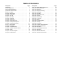
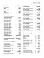
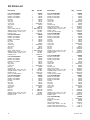
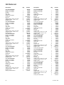
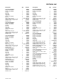
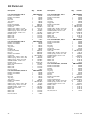
Table of Contents
Product Identification Information . . . . . . . . . . . . . . . . . . . . . . . . . . . . . . . . . . . . . . . . . . . . . . . . . . . . . . . . . . . . 2
Safety Precautions and Instructions . . . . . . . . . . . . . . . . . . . . . . . . . . . . . . . . . . . . . . . . . . . . . . . . . . . . . . . .
5
Introduction . . . . . . . . . . . . . . . . . . . . . . . . . . . . . . . . . . . . . . . . . . . . . . . . . . . . . . . . . . . . . . . . . . . . . . . . . . . . . . .
Abbreviations . . . . . . . . . . . . . . . . . . . . . . . . . . . . . . . . . . . . . . . . . . . . . . . . . . . . . . . . . . . . . .
List of Related Materials . . . . . . . . . . . . . . . . . . . . . . . . . . . . . . . . . . . . . . . . . . . . . . . . . . . . .
9
9
9
Service Assistance . . . . . . . . . . . . . . . . . . . . . . . . . . . . . . . . . . . . . . . . . . . . . . . . . . . . . . . . . . . . . . . . . . . . . . . . 10
TP-6161
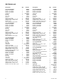
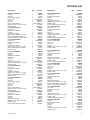
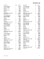
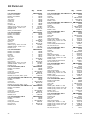
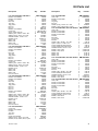
Section 1 Specifications and Features . . . . . . . . . . . . . . . . . . . . . . . . . . . . . . . . . . . . . . . . . . . . . . . . . . . . . .
1.1 Introduction . . . . . . . . . . . . . . . . . . . . . . . . . . . . . . . . . . . . . . . . . . . . . . . . . . . . . . . . . .
1.2 16-Light Controller Features . . . . . . . . . . . . . . . . . . . . . . . . . . . . . . . . . . . . . . . . . . . .
1.2.1
Annunciator Panel Lamps . . . . . . . . . . . . . . . . . . . . . . . . . . . . . . . . . . . . . .
1.2.2
Auxiliary Fault Lamp . . . . . . . . . . . . . . . . . . . . . . . . . . . . . . . . . . . . . . . . . . .
1.2.3
Fuses . . . . . . . . . . . . . . . . . . . . . . . . . . . . . . . . . . . . . . . . . . . . . . . . . . . . . . .
1.2.4
Analog Meters and Gauges . . . . . . . . . . . . . . . . . . . . . . . . . . . . . . . . . . . . .
1.2.5
Switches and Controls . . . . . . . . . . . . . . . . . . . . . . . . . . . . . . . . . . . . . . . . .
1.2.6
Terminal Strips . . . . . . . . . . . . . . . . . . . . . . . . . . . . . . . . . . . . . . . . . . . . . . . .
1.2.7
DIP Switches . . . . . . . . . . . . . . . . . . . . . . . . . . . . . . . . . . . . . . . . . . . . . . . . .
1.3 Expanded Decision-Maker 1 Controller . . . . . . . . . . . . . . . . . . . . . . . . . . . . . . . . . . .
11
11
11
12
13
13
13
14
14
15
16
Section 2 Operation . . . . . . . . . . . . . . . . . . . . . . . . . . . . . . . . . . . . . . . . . . . . . . . . . . . . . . . . . . . . . . . . . . . . . . .
2.1 Prestart Checklist . . . . . . . . . . . . . . . . . . . . . . . . . . . . . . . . . . . . . . . . . . . . . . . . . . . . .
2.2 Generator Set Exercising . . . . . . . . . . . . . . . . . . . . . . . . . . . . . . . . . . . . . . . . . . . . . . .
2.3 16-Light Controller Features . . . . . . . . . . . . . . . . . . . . . . . . . . . . . . . . . . . . . . . . . . . .
2.3.1
Normal Operation . . . . . . . . . . . . . . . . . . . . . . . . . . . . . . . . . . . . . . . . . . . . .
2.3.2
Prime Power Mode Operation . . . . . . . . . . . . . . . . . . . . . . . . . . . . . . . . . .
2.3.3
Emergency Stopping . . . . . . . . . . . . . . . . . . . . . . . . . . . . . . . . . . . . . . . . . .
2.3.4
Fault Shutdowns . . . . . . . . . . . . . . . . . . . . . . . . . . . . . . . . . . . . . . . . . . . . . .
2.3.5
Controller Resetting After a Fault Shutdown . . . . . . . . . . . . . . . . . . . . . . .
2.4 Expanded Decision-Maker 1 Controller . . . . . . . . . . . . . . . . . . . . . . . . . . . . . . . . . . .
2.4.1
Generator Set Starting . . . . . . . . . . . . . . . . . . . . . . . . . . . . . . . . . . . . . . . . .
2.4.2
Generator Set Stopping . . . . . . . . . . . . . . . . . . . . . . . . . . . . . . . . . . . . . . . .
2.4.3
Fault Shutdowns . . . . . . . . . . . . . . . . . . . . . . . . . . . . . . . . . . . . . . . . . . . . . .
2.4.4
Controller Resetting After a Fault Shutdown . . . . . . . . . . . . . . . . . . . . . . .
17
17
17
17
17
18
18
19
19
20
20
20
20
20
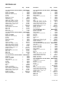
Section 3 Scheduled Maintenance . . . . . . . . . . . . . . . . . . . . . . . . . . . . . . . . . . . . . . . . . . . . . . . . . . . . . . . . . .
3.1 Alternator Service . . . . . . . . . . . . . . . . . . . . . . . . . . . . . . . . . . . . . . . . . . . . . . . . . . . . .
3.2 Engine Service . . . . . . . . . . . . . . . . . . . . . . . . . . . . . . . . . . . . . . . . . . . . . . . . . . . . . . .
3.3 Service Schedule . . . . . . . . . . . . . . . . . . . . . . . . . . . . . . . . . . . . . . . . . . . . . . . . . . . . .
3.4 Alternator Bearing Service . . . . . . . . . . . . . . . . . . . . . . . . . . . . . . . . . . . . . . . . . . . . . .
3.4.1
20--300 kW Models . . . . . . . . . . . . . . . . . . . . . . . . . . . . . . . . . . . . . . . . . . . .
3.4.2
350--2000 kW Models with Single- Bearing Alternator . . . . . . . . . . . . . .
3.4.3
1250--2000 kW Model with Two- Bearing Alternator . . . . . . . . . . . . . . . .
3.5 Diesel Fuel Systems . . . . . . . . . . . . . . . . . . . . . . . . . . . . . . . . . . . . . . . . . . . . . . . . . . .
3.5.1
Bleeding Air from Fuel System . . . . . . . . . . . . . . . . . . . . . . . . . . . . . . . . . .
3.5.2
Subbase Inner Fuel Tank Alarm . . . . . . . . . . . . . . . . . . . . . . . . . . . . . . . . .
3.6 Gas/Gasoline Fuel Systems . . . . . . . . . . . . . . . . . . . . . . . . . . . . . . . . . . . . . . . . . . . .
3.6.1
Gaseous Fuel System Concept . . . . . . . . . . . . . . . . . . . . . . . . . . . . . . . . .
3.6.2
LP Liquid Withdrawal Fuel System Concept . . . . . . . . . . . . . . . . . . . . . . .
3.6.3
LP Gas/Natural Gas Conversion for Straight Gas Fuel System . . . . . . .
3.6.4
Fuel System Changeover Kits . . . . . . . . . . . . . . . . . . . . . . . . . . . . . . . . . . .
3.6.5
Carburetor Adjustment . . . . . . . . . . . . . . . . . . . . . . . . . . . . . . . . . . . . . . . . .
3.6.6
Fuel System Maintenance . . . . . . . . . . . . . . . . . . . . . . . . . . . . . . . . . . . . . .
21
21
21
22
24
24
24
24
24
24
25
25
25
26
26
27
27
27
1/08
Table of Contents
3
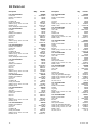
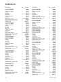
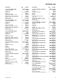
Table of Contents, continued
3.7
3.8
3.9
3.10
3.11
3.12
3.13
Cooling System . . . . . . . . . . . . . . . . . . . . . . . . . . . . . . . . . . . . . . . . . . . . . . . . . . . . . . .
3.7.1
Coolant Level Check . . . . . . . . . . . . . . . . . . . . . . . . . . . . . . . . . . . . . . . . . . .
3.7.2
Cooling System Component Inspection . . . . . . . . . . . . . . . . . . . . . . . . . . .
3.7.3
Cooling System Drainage Procedure . . . . . . . . . . . . . . . . . . . . . . . . . . . . .
3.7.4
Cooling System Flush and Clean Procedure . . . . . . . . . . . . . . . . . . . . . .
3.7.5
Cooling System Refilling Procedure . . . . . . . . . . . . . . . . . . . . . . . . . . . . . .
Radiator Fan Bolt Retorque . . . . . . . . . . . . . . . . . . . . . . . . . . . . . . . . . . . . . . . . . . . . .
Radiator Fan Bearing Lubrication . . . . . . . . . . . . . . . . . . . . . . . . . . . . . . . . . . . . . . . .
Battery . . . . . . . . . . . . . . . . . . . . . . . . . . . . . . . . . . . . . . . . . . . . . . . . . . . . . . . . . . . . . . .
3.10.1 Cleaning . . . . . . . . . . . . . . . . . . . . . . . . . . . . . . . . . . . . . . . . . . . . . . . . . . . . .
3.10.2 Electrolyte Level Inspection . . . . . . . . . . . . . . . . . . . . . . . . . . . . . . . . . . . . .
3.10.3 Specific Gravity Check . . . . . . . . . . . . . . . . . . . . . . . . . . . . . . . . . . . . . . . . .
3.10.4 Charging . . . . . . . . . . . . . . . . . . . . . . . . . . . . . . . . . . . . . . . . . . . . . . . . . . . . .
Detroit Diesel Engine Control Systems . . . . . . . . . . . . . . . . . . . . . . . . . . . . . . . . . . .
3.11.1 Features . . . . . . . . . . . . . . . . . . . . . . . . . . . . . . . . . . . . . . . . . . . . . . . . . . . . .
3.11.2 DDEC Engine Diagnostics . . . . . . . . . . . . . . . . . . . . . . . . . . . . . . . . . . . . . .
Engine Control Systems . . . . . . . . . . . . . . . . . . . . . . . . . . . . . . . . . . . . . . . . . . . . . . . .
Storage Procedure . . . . . . . . . . . . . . . . . . . . . . . . . . . . . . . . . . . . . . . . . . . . . . . . . . . .
3.13.1 Lubricating System . . . . . . . . . . . . . . . . . . . . . . . . . . . . . . . . . . . . . . . . . . . .
3.13.2 Cooling System . . . . . . . . . . . . . . . . . . . . . . . . . . . . . . . . . . . . . . . . . . . . . . .
3.13.3 Fuel System . . . . . . . . . . . . . . . . . . . . . . . . . . . . . . . . . . . . . . . . . . . . . . . . . .
3.13.4 Internal Engine Components (Gas/Gasoline-Fueled Engines) . . . . . . .
3.13.5 Exterior . . . . . . . . . . . . . . . . . . . . . . . . . . . . . . . . . . . . . . . . . . . . . . . . . . . . . .
3.13.6 Battery . . . . . . . . . . . . . . . . . . . . . . . . . . . . . . . . . . . . . . . . . . . . . . . . . . . . . . .
28
28
28
28
29
29
29
30
31
33
33
33
34
34
34
34
35
35
35
35
36
36
36
36
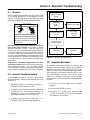
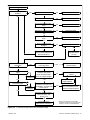
Section 4 Troubleshooting . . . . . . . . . . . . . . . . . . . . . . . . . . . . . . . . . . . . . . . . . . . . . . . . . . . . . . . . . . . . . . . . . 37
Section 5 Generator Set Reconnection . . . . . . . . . . . . . . . . . . . . . . . . . . . . . . . . . . . . . . . . . . . . . . . . . . . . . 41
4
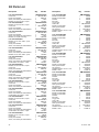
Section 6 Accessories . . . . . . . . . . . . . . . . . . . . . . . . . . . . . . . . . . . . . . . . . . . . . . . . . . . . . . . . . . . . . . . . . . . . .
6.1 Accessories . . . . . . . . . . . . . . . . . . . . . . . . . . . . . . . . . . . . . . . . . . . . . . . . . . . . . . . . . .
6.1.1
Audiovisual Alarm (M) . . . . . . . . . . . . . . . . . . . . . . . . . . . . . . . . . . . . . . . . . .
6.1.2
Common Failure Relay Kit (M) . . . . . . . . . . . . . . . . . . . . . . . . . . . . . . . . . .
6.1.3
Controller Connection Kit (M) . . . . . . . . . . . . . . . . . . . . . . . . . . . . . . . . . . .
6.1.4
Dry Contact Kit (Single-Relay) (M) . . . . . . . . . . . . . . . . . . . . . . . . . . . . . . .
6.1.5
Dry Contact Kits (10-, 14-, and 20-Relay) (M) . . . . . . . . . . . . . . . . . . . . .
6.1.6
Engine Prealarm Senders (M) . . . . . . . . . . . . . . . . . . . . . . . . . . . . . . . . . . .
6.1.7
FASTCHECK Diagnostic Tester (M) . . . . . . . . . . . . . . . . . . . . . . . . . . . . . .
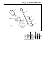
6.1.8
Float/Equalize Battery Charger Kit with Alarm Option (M) . . . . . . . . . . .
6.1.9
Line Circuit Breaker . . . . . . . . . . . . . . . . . . . . . . . . . . . . . . . . . . . . . . . . . . .
6.1.10 Low Fuel Switch (M) . . . . . . . . . . . . . . . . . . . . . . . . . . . . . . . . . . . . . . . . . . .
6.1.11 Remote Annunciator Kit (M) . . . . . . . . . . . . . . . . . . . . . . . . . . . . . . . . . . . .
6.1.12 Remote Emergency Stop Kit (M) . . . . . . . . . . . . . . . . . . . . . . . . . . . . . . . .
6.1.13 Remote Serial Annunciator (M) . . . . . . . . . . . . . . . . . . . . . . . . . . . . . . . . . .
6.1.14 Run Relay Kit . . . . . . . . . . . . . . . . . . . . . . . . . . . . . . . . . . . . . . . . . . . . . . . . .
6.1.15 Safeguard Breaker . . . . . . . . . . . . . . . . . . . . . . . . . . . . . . . . . . . . . . . . . . . .
6.2 Accessory and Prime Power Terminal Strip Connections (M) . . . . . . . . . . . . . . . .
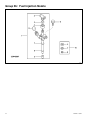
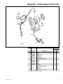
6.3 Communication Module Kit and Gauge Driver Circuit Board . . . . . . . . . . . . . . . . .
6.3.1
Communication Modules (Circuit Board) Versions . . . . . . . . . . . . . . . . . .
6.3.2
Circuit Boards Views . . . . . . . . . . . . . . . . . . . . . . . . . . . . . . . . . . . . . . . . . . .
47
47
47
47
47
48
48
49
49
49
49
50
50
50
51
51
51
52
54
55
55
Appendix A Abbreviations . . . . . . . . . . . . . . . . . . . . . . . . . . . . . . . . . . . . . . . . . . . . . . . . . . . . . . . . . . . . . . . .
57
Table of Contents
TP-6161
1/08
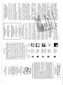
Safety Precautions and Instructions
IMPORTANT SAFETY INSTRUCTIONS.
Electromechanical
equipment,
including generator sets, transfer
switches, switchgear, and accessories,
can cause bodily harm and pose
life-threatening
danger
when
improperly installed, operated, or
maintained. To prevent accidents be
aware of potential dangers and act
safely. Read and follow all safety
precautions and instructions. SAVE
THESE INSTRUCTIONS.
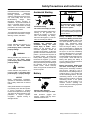
This manual has several types of safety
precautions and instructions: Danger,
Warning, Caution, and Notice.
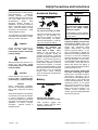
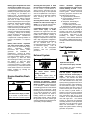
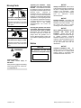
Accidental Starting
WARNING
Accidental starting.
Can cause severe injury or death.
Disconnect the battery cables before
working on the generator set.
Remove the negative (--) lead first
when disconnecting the battery.
Reconnect the negative (--) lead last
when reconnecting the battery.
DANGER
Danger indicates the presence of a
hazard that will cause severe
personal injury, death, or substantial
property damage.
WARNING
Warning indicates the presence of a
hazard that can cause severe
personal injury, death, or substantial
property damage.
CAUTION
Caution indicates the presence of a
hazard that will or can cause minor
personal injury or property damage.
Disabling
the
generator set.
Accidental starting can cause
severe injury or death.
Before
working on the generator set or
connected equipment, disable the
generator set as follows: (1) Move the
generator set master switch to the OFF
position. (2) Disconnect the power to
the battery charger. (3) Remove the
battery cables, negative (--) lead first.
Reconnect the negative (--) lead last
when reconnecting the battery. Follow
these precautions to prevent starting of
the generator set by an automatic
transfer switch, remote start/stop
switch, or engine start command from a
remote computer.
Battery
NOTICE
Notice communicates installation,
operation, or maintenance information
that is safety related but not hazard
related.
Safety decals affixed to the equipment
in prominent places alert the operator
or service technician to potential
hazards and explain how to act safely.
The decals are shown throughout this
publication to improve operator
recognition.
Replace missing or
damaged decals.
TP-6161
1/08
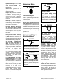
WARNING
WARNING
Explosion.
Can cause severe injury or death.
Relays in the battery charger
cause arcs or sparks.
Locate the battery in a well-ventilated
area. Isolate the battery charger from
explosive fumes.
Battery electrolyte is a diluted
sulfuric acid. Battery acid can cause
severe injury or death. Battery acid
can cause blindness and burn skin.
Always wear splashproof safety
goggles, rubber gloves, and boots
when servicing the battery. Do not
open a sealed battery or mutilate the
battery case. If battery acid splashes in
the eyes or on the skin, immediately
flush the affected area for 15 minutes
with large quantities of clean water.
Seek immediate medical aid in the case
of eye contact. Never add acid to a
battery after placing the battery in
service, as this may result in hazardous
spattering of battery acid.
Battery acid cleanup. Battery acid
can cause severe injury or death.
Battery acid is electrically conductive
and corrosive. Add 500 g (1 lb.) of
bicarbonate of soda (baking soda) to a
container with 4 L (1 gal.) of water and
mix the neutralizing solution. Pour the
neutralizing solution on the spilled
battery acid and continue to add the
neutralizing solution to the spilled
battery acid until all evidence of a
chemical reaction (foaming) has
ceased. Flush the resulting liquid with
water and dry the area.
Sulfuric acid in batteries.
Can cause severe injury or death.
Wear protective goggles and
clothing. Battery acid may cause
blindness and burn skin.
Safety Precautions and Instructions
5
Battery gases. Explosion can cause
severe injury or death. Battery gases
can cause an explosion. Do not smoke
or permit flames or sparks to occur near
a battery at any time, particularly when
it is charging. Do not dispose of a
battery in a fire. To prevent burns and
sparks that could cause an explosion,
avoid touching the battery terminals
with tools or other metal objects.
Remove all jewelry before servicing the
equipment. Discharge static electricity
from your body before touching
batteries by first touching a grounded
metal surface away from the battery. To
avoid sparks, do not disturb the battery
charger connections while the battery
is charging. Always turn the battery
charger off before disconnecting the
battery connections. Ventilate the
compartments containing batteries to
prevent accumulation of explosive
gases.
Battery short circuits. Explosion
can cause severe injury or death.
Short circuits can cause bodily injury
and/or
equipment
damage.
Disconnect
the
battery
before
generator
set
installation
or
maintenance. Remove all jewelry
before servicing the equipment. Use
tools with insulated handles. Remove
the negative (--) lead first when
disconnecting the battery. Reconnect
the negative (--) lead last when
reconnecting the battery.
Never
connect the negative (--) battery cable
to the positive (+) connection terminal
of the starter solenoid. Do not test the
battery condition by shorting the
terminals together.
Engine Backfire/Flash
Fire
WARNING
Fire.
Can cause severe injury or death.
Do not smoke or permit flames or
sparks near fuels or the fuel system.
6
Safety Precautions and Instructions
Servicing the fuel system. A flash
fire can cause severe injury or death.
Do not smoke or permit flames or
sparks near the carburetor, fuel line,
fuel filter, fuel pump, or other potential
sources of spilled fuels or fuel vapors.
Catch fuels in an approved container
when removing the fuel line or
carburetor.
Servicing the air cleaner. A sudden
backfire can cause severe injury or
death. Do not operate the generator
set with the air cleaner removed.
Combustible materials. A fire can
cause severe injury or death.
Generator set engine fuels and fuel
vapors are flammable and explosive.
Handle these materials carefully to
minimize the risk of fire or explosion.
Equip the compartment or nearby area
with a fully charged fire extinguisher.
Select a fire extinguisher rated ABC or
BC for electrical fires or as
recommended by the local fire code or
an authorized agency.
Train all
personnel
on
fire extinguisher
operation
and
fire
prevention
procedures.
Exhaust System
Carbon
monoxide
symptoms.
Carbon monoxide can cause severe
nausea, fainting, or death. Carbon
monoxide is a poisonous gas present in
exhaust gases. Carbon monoxide is an
odorless,
colorless,
tasteless,
nonirritating gas that can cause death if
inhaled for even a short time. Carbon
monoxide poisoning symptoms include
but are not limited to the following:
D Light-headedness, dizziness
D Physical fatigue, weakness in
joints and muscles
D Sleepiness, mental fatigue,
inability to concentrate
or speak clearly, blurred vision
D Stomachache, vomiting, nausea
If experiencing any of these symptoms
and carbon monoxide poisoning is
possible, seek fresh air immediately
and remain active. Do not sit, lie down,
or fall asleep. Alert others to the
possibility of carbon monoxide
poisoning. Seek medical attention if
the condition of affected persons does
not improve within minutes of breathing
fresh air.
Fuel System
WARNING
WARNING
Carbon monoxide.
Can cause severe
fainting, or death.
Explosive fuel vapors.
Can cause severe injury or death.
nausea,
The exhaust system must be
leakproof and routinely inspected.
Generator set operation. Carbon
monoxide can cause severe nausea,
fainting, or death. Carbon monoxide
is an odorless, colorless, tasteless,
nonirritating gas that can cause death if
inhaled for even a short time. Avoid
breathing exhaust fumes when working
on or near the generator set. Never
operate the generator set inside a
building unless the exhaust gas is
piped safely outside. Never operate
the generator set where exhaust gas
could accumulate and seep back inside
a potentially occupied building.
Use extreme care when handling,
storing, and using fuels.
The fuel system. Explosive fuel
vapors can cause severe injury or
death. Vaporized fuels are highly
explosive. Use extreme care when
handling and storing fuels. Store fuels
in a well-ventilated area away from
spark-producing equipment and out of
the reach of children. Never add fuel to
the tank while the engine is running
because spilled fuel may ignite on
contact with hot parts or from sparks.
Do not smoke or permit flames or
sparks to occur near sources of spilled
fuel or fuel vapors. Keep the fuel lines
and connections tight and in good
condition. Do not replace flexible fuel
lines with rigid lines. Use flexible
sections to avoid fuel line breakage
caused by vibration. Do not operate the
generator set in the presence of fuel
TP-6161
1/08
leaks, fuel accumulation, or sparks.
Repair fuel systems before resuming
generator set operation.
Explosive fuel vapors can cause
severe injury or death.
Take
additional precautions when using the
following fuels:
Gasoline—Store gasoline only in
approved red containers clearly
marked GASOLINE.
Propane (LP)—Adequate ventilation
is mandatory. Because propane is
heavier than air, install propane gas
detectors low in a room. Inspect the
detectors per the manufacturer’s
instructions.
Natural Gas—Adequate ventilation is
mandatory. Because natural gas rises,
install natural gas detectors high in a
room. Inspect the detectors per the
manufacturer’s instructions.
Fuel tanks. Explosive fuel vapors
can cause severe injury or death.
Gasoline and other volatile fuels stored
in day tanks or subbase fuel tanks can
cause an explosion. Store only diesel
fuel in tanks.
Draining the fuel system. Explosive
fuel vapors can cause severe injury
or death. Spilled fuel can cause an
explosion. Use a container to catch fuel
when draining the fuel system. Wipe up
spilled fuel after draining the system.
Gas fuel leaks.
Explosive fuel
vapors can cause severe injury or
death. Fuel leakage can cause an
explosion. Check the LP vapor gas or
natural gas fuel system for leakage by
using a soap and water solution with
the fuel system test pressurized to
6--8 ounces
per
square
inch
(10--14 inches water column). Do not
use a soap solution containing either
ammonia or chlorine because both
prevent bubble formation. A successful
test depends on the ability of the
solution to bubble.
LP liquid withdrawal fuel leaks.
Explosive fuel vapors can cause
severe injury or death. Fuel leakage
can cause an explosion. Check the LP
liquid withdrawal gas fuel system for
leakage by using a soap and water
solution with the fuel system test
pressurized to at least 90 psi
(621 kPa). Do not use a soap solution
containing either ammonia or chlorine
because
both
prevent
bubble
formation. A successful test depends
on the ability of the solution to bubble.
TP-6161
1/08
Hazardous Noise
WARNING
CAUTION
Hazardous noise.
Can cause hearing loss.
Never operate the generator set
without a muffler or with a faulty
exhaust system.
Engine noise. Hazardous noise can
cause hearing loss. Generator sets
not equipped with sound enclosures
can produce noise levels greater than
105 dBA. Prolonged exposure to noise
levels greater than 85 dBA can cause
permanent hearing loss. Wear hearing
protection when near an operating
generator set.
Hazardous Voltage/
Moving Parts
DANGER
Hazardous voltage.
Will cause severe injury or death.
Disconnect all power sources before
opening the enclosure.
WARNING
Hazardous voltage. Moving parts.
Can cause severe injury or death.
Operate the generator set only when
all guards and electrical enclosures
are in place.
Hazardous voltage.
Backfeed to the utility system can
cause property damage, severe
injury, or death.
If the generator set is used for
standby power, install an automatic
transfer switch to prevent inadvertent
interconnection of standby and
normal sources of supply.
Grounding electrical equipment.
Hazardous voltage can cause
severe injury or death. Electrocution
is possible whenever electricity is
present. Ensure you comply with all
applicable codes and standards.
Electrically ground the generator set,
transfer switch, and related equipment
and electrical circuits. Turn off the main
circuit breakers of all power sources
before servicing the equipment. Never
contact electrical leads or appliances
when standing in water or on wet
ground because these conditions
increase the risk of electrocution.
Installing the battery charger.
Hazardous voltage can cause
severe injury or death.
An
ungrounded battery charger may
cause electrical shock. Connect the
battery charger enclosure to the ground
of a permanent wiring system. As an
alternative, install an equipment
grounding conductor with circuit
conductors and connect it to the
equipment grounding terminal or the
lead on the battery charger. Install the
battery charger as prescribed in the
equipment manual. Install the battery
charger in compliance with local codes
and ordinances.
Connecting the battery and the
battery charger. Hazardous voltage
can cause severe injury or death.
Reconnect the battery correctly,
positive to positive and negative to
negative, to avoid electrical shock and
damage to the battery charger and
battery(ies).
Have a qualified
electrician install the battery(ies).
Safety Precautions and Instructions
7
Short
circuits.
Hazardous
voltage/current can cause severe
injury or death. Short circuits can
cause bodily injury and/or equipment
damage. Do not contact electrical
connections with tools or jewelry while
making adjustments or repairs.
Remove all jewelry before servicing the
equipment.
Engine block heater. Hazardous
voltage can cause severe injury or
death. The engine block heater can
cause electrical shock. Remove the
engine block heater plug from the
electrical outlet before working on the
block heater electrical connections.
Handling the capacitor. Hazardous
voltage can cause severe injury or
death. Electrical shock results from
touching the charged capacitor
terminals. Discharge the capacitor by
shorting the terminals together.
(Capacitor-excited models only)
Electrical backfeed to the utility.
Hazardous backfeed voltage can
cause severe injury or death. Install
a transfer switch in standby power
installations to prevent the connection
of standby and other sources of power.
Electrical backfeed into a utility
electrical system can cause severe
injury or death to utility personnel
working on power lines.
Testing live electrical circuits.
Hazardous voltage or current can
cause severe injury or death. Have
trained and qualified personnel take
diagnostic measurements of live
circuits. Use adequately rated test
equipment with electrically insulated
probes and follow the instructions of the
test equipment manufacturer when
performing voltage tests. Observe the
following precautions when performing
voltage tests: (1) Remove all jewelry.
(2) Stand on a dry, approved electrically
insulated mat. (3) Do not touch the
enclosure or components inside the
enclosure. (4) Be prepared for the
system to operate automatically.
(600 volts and under)
WARNING
WARNING
Airborne particles.
Can cause severe
blindness.
Hot engine and exhaust system.
Can cause severe injury or death.
injury
or
Wear protective goggles and clothing
when using power tools, hand tools,
or compressed air.
Servicing the generator set when it
is operating. Exposed moving parts
can cause severe injury or death.
Keep hands, feet, hair, clothing, and
test leads away from the belts and
pulleys when the generator set is
running. Replace guards, screens, and
covers before operating the generator
set.
Do not work on the generator set until
it cools.
Servicing the alternator. Hot parts
can cause severe injury or death.
Avoid touching the alternator field or
exciter armature. When shorted, the
alternator field and exciter armature
become hot enough to cause severe
burns.
Servicing the exhaust system. Hot
parts can cause severe injury or
death. Do not touch hot engine parts.
The engine and exhaust system
components become extremely hot
during operation.
Heavy Equipment
Notice
WARNING
NOTICE
This generator set has been
rewired from its nameplate voltage
to
Unbalanced weight.
Improper lifting can cause severe
injury or death and equipment
damage.
Do not use lifting eyes.
Lift the generator set using lifting bars
inserted through the lifting holes on
the skid.
Hot Parts
WARNING
Hot coolant and steam.
Can cause severe injury or death.
246242
NOTICE
Voltage reconnection. Affix a notice
to the generator set after reconnecting
the set to a voltage different from the
voltage on the nameplate. Order
voltage reconnection decal 246242
from
an
authorized
service
distributor/dealer.
NOTICE
Canadian installations only. For
standby service connect the output of
the generator set to a suitably rated
transfer switch in accordance with
Canadian Electrical Code, Part 1.
Before removing the pressure cap,
stop the generator set and allow it to
cool. Then loosen the pressure cap
to relieve pressure.
8
Safety Precautions and Instructions
TP-6161
1/08
Introduction
This manual provides operation instructions for
20--2250 kW generator sets equipped with the following
controllers:
Communication and Software
Manual Description
Literature Part No.
16-Light Controller Spec Sheet
G6-30
D Decision-Maker™ 3+, 16-Light
Decision-Makert1 Controller
Spec Sheet
G6-29
D Decision-Maker™ 1
Wiring diagram manuals are available separately. Refer
to the engine operation manual for generator set engine
scheduled maintenance information.
Information in this publication represents data available
at the time of print. Kohler Co. reserves the right to
change this publication and the products represented
without notice and without any obligation or liability
whatsoever.
Multiple Part Numbers
Contact your
Distributor/Dealer
Generator Set/Controller
Wiring Diagram Manual
Modbusr Communications Protocol
Operation Manual
TP-6113
Service Parts Controllers
TP-6009
Program Loader Software Installation
TT-1285
Remote Serial Annunciator (RSA)
TT-1377
Controller Service Replacement
TT-1310
Monitor III Converters, Connections,
and Controller Setup
TT-1405
Read this manual and carefully follow all procedures
and safety precautions to ensure proper equipment
operation and to avoid bodily injury. Read and follow the
Safety Precautions and Instructions section at the
beginning of this manual. Keep this manual with the
equipment for future reference.
Figure 1
The equipment service requirements are very important
to safe and efficient operation. Inspect the parts often
and perform required service at the prescribed intervals.
Maintenance work must be performed by appropriately
skilled and suitably trained maintenance personnel
familiar with generator set operation and service.
Several engine manufacturers provide engines with
electronic controls. These electronic controls indicate
fault codes in addition to the generator set controller.
Use Figure 2 for literature part numbers relating to the
identifying engine fault codes. For the latest literature
part numbers, see the respective Parts Catalog.
Abbreviations
This publication makes use of numerous abbreviations.
Typically, the word(s) are spelled out along with the
abbreviation in parentheses when shown for the first
time in a section. Appendix A, Abbreviations, also
includes many abbreviation definitions.
List of Related Materials
Separate literature contains communication and
software information for the 16-Light Controller with
communications not provided in this manual. Figure 1
lists the available literature part numbers.
Monitor III Software Spec Sheet
G6-76
Monitor III Converter,
Modbusr/Ethernet Spec Sheet
G6-79
Monitor III Software Operation Manual
TP-6347
Related Literature
Literature
Part No. Description
Model
30 kW and
80--125 kW GM
TP-6215
Engine ECM Service Manual
80--200 kW John
Deere 4045/6068
TP-6285
Engine Operation Manual
275--500 kW Kohler
Branded Engines
TP-6218
Engine Operation Manual
135--275 kW DDC
Series 50/60 Gas
TP-5830
Natural Gas Generator Set
Engine Operator’s Guide
230--450 kW DDC
Series 60
TP-6056
DDEC IV Application and
Installation Manual
230--450 kW DDC
Series 60
TP-5611
Engine Operator’s Guide
450/500 kW DDC
Series 2000
TP-6361
DDEC IV ECM
Troubleshooting Guide
650--1000 kW DDC
Series 2000
TP-6375
Engine Operating
Instructions (MDEC)
650--1000 kW
DDC/MTU Series 2000 TP-6502
Engine Operating
Instructions (ADEC)
1250--2250 kW
DDC/MTU Series 4000 TP-6503
Engine Operating
Instructions (ADEC)
1350--2000 kW
DDC/MTU Series 4000 TP-6237
Engine Operating
Instructions (MDEC)
Figure 2
Related Engine Literature
Modbusr is a registered trademark of Schneider Electric.
TP-6161
1/08
Introduction
9
Tech Tools
Use your SecurID to access the KOHLERnet and click
on Tech Tools button to find the following topics:
D Software used by generator set controllers including
updates and documentation references.
D Network Communications provides basics to
terms, protocols, standards, wiring, configurations,
and model.
D Engine Electronic Control Module (ECM) has
information about electronic devices provided by the
engine manufacturer to manage engine data.
Service Assistance
For professional advice on generator set power
requirements and conscientious service, please contact
your nearest Kohler distributor or dealer.
D Consult the Yellow Pages under the heading
Generators—Electric.
D Visit
the Kohler Power Systems website at
KohlerPower.com.
D Look at the labels and stickers on your Kohler product
or review the appropriate literature or documents
included with the product.
D Call toll free in the US and Canada 1-800-544-2444.
D Outside the US and Canada, call the nearest regional
office.
Headquarters Europe, Middle East, Africa
(EMEA)
Kohler Power Systems
3 rue de Brennus
93200 Saint Denis
France
Phone: (33) 1 49 178300
Fax: (33) 1 49 178301
China
North China Regional Office, Beijing
Phone: (86) 10 6518 7950
(86) 10 6518 7951
(86) 10 6518 7952
Fax: (86) 10 6518 7955
East China Regional Office, Shanghai
Phone: (86) 21 6288 0500
Fax: (86) 21 6288 0550
India, Bangladesh, Sri Lanka
India Regional Office
Bangalore, India
Phone: (91) 80 3366208
(91) 80 3366231
Fax: (91) 80 3315972
Japan, Korea
North Asia Regional Office
Tokyo, Japan
Phone: (813) 3440-4515
Fax: (813) 3440-2727
Latin America
Latin America Regional Office
Lakeland, Florida, USA
Phone: (863) 619-7568
Fax: (863) 701-7131
Asia Pacific
Power Systems Asia Pacific Regional Office
Singapore, Republic of Singapore
Phone: (65) 6264-6422
Fax: (65) 6264-6455
10
Service Assistance
TP-6161
1/08
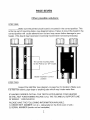
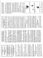
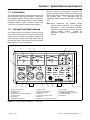
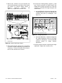
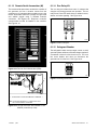
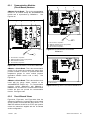
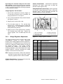
Section 1 Specifications and Features
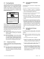
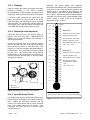
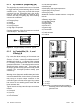
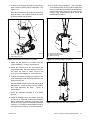
Figure 1-1 shows the 16-light (level 1) controller. The
16-light controller features include annunciator panel
lamps, analog meters, switches and controls, and fuses
and terminal strips.
For identification and an
explanation of the functions, see Sections 1.2.1 through
1.2.7.
1.1 Introduction
The specification sheets for each generator set provide
specific generator and engine information. Refer to the
respective specification sheet for data not supplied in
this manual. Consult the generator set service manual,
installation manual, engine operation manual, and
engine service manual for additional specifications.
Note: Some installations use modified 16-light
microprocessor controllers with switchgear
applications. These nonstandard controllers
may have remote start and no time delay for
engine cooldown circuitry.
Consult the
switchgear literature for configuration and
function.
1.2 16-Light Controller Features
The 16-light controller can operate in either the normal
mode or the prime power mode. The prime power mode
allows reduced controller current draw in applications
without a battery charger, minimizing battery drain by
the controller circuitry. See Section 2.3.2, Prime Power
Mode Operation, for more information.
1
2
3
4
5
6
∅
7
∅
18
8
9
17
1.
2.
3.
4.
16
15
Fuses (inside controller)
Frequency meter
AC voltmeter
Controller TB1 and TP2 terminal strips
(on circuit board)
5. AC ammeter
6. Scale lamps (upper/lower)
Figure 1-1
TP-6161
14
7.
8.
9.
10.
11.
12.
13.
13
12
Selector switch
Annunciator panel lamps
Alarm silence switch
Lamp test
Generator set master switch
Alarm horn
Emergency stop switch (if equipped)
11
14.
15.
16.
17.
18.
10
ADV-5849A
DC voltmeter
Water temperature gauge
Voltage adjustment (if equipped)
Oil pressure gauge
Hourmeter
16-Light Decision-Maker 3+t Controller
1/08
Section 1 Specifications and Features
11
The 16-light controller with communications has a new
circuit board GM28725 that is different in appearance
and has additional functions from the earlier versions
but is a direct replacement for earlier version circuit
boards including A-336415. Features of the new
circuit board include the following items:
D Red circuit board, previous versions are green.
D Terminal strips (TB1, TB2, and TB3).
D SW1 DIP switch (8 switches).
D Communication connector P21 for Modbusr to
New Application Program Software. Contact your
local authorized distributor for application program
updates when instructed to do so during troubleshooting
and/or when adding specific accessories. Refer to
TT-1285 Program Loader Software instruction for
additional download information.
1.2.1
Annunciator Panel Lamps
Figure 1-2 lists the annunciator lamps included on each
controller and describes the lamp functions.
download new application program software or to
connect the remote serial annunciator using RS-485
communications.
Requires RS-485 to RS-232
converter for downloading application program.
D Communication connector P22 for J1939 engine
communication.
Lamp
Description
Air damper
This light is not used on current standard products.
Auxiliary fault
Flashes or lights upon fault detection. Figure 1-3 describes auxiliary fault conditions.
High engine
temperature
Lights if the engine has shut down because of high engine temperature. The shutdown occurs 5 seconds after the
engine reaches temperature shutdown range.
Low oil pressure
Lamp lights if the generator set shuts down because of insufficient oil pressure. The shutdown occurs 5 seconds
after the engine reaches temperature shutdown range.
Overspeed
Lamp lights if the generator set shuts down because the governed frequency on 50/60 Hz models exceeds
60/70 Hz.
Overcrank
Cranking stops and the lamp lights if the engine does not start after 30 seconds of continuous cranking or
75 seconds of cyclic cranking. See Section 2.3.1, Normal Operation.
Note:
The engine ECM may limit the crank cycle even if the controller is set to a longer time period.
Cranking stops and the overcrank lamp lights after 25 seconds if the starter or engine does not turn (locked rotor).
The overcrank lamp flashes if the speed sensor signal is absent for longer than one second.
Low water
temperature
Lights if water temperature falls below the minimum preset temperature. This lamp may require an optional
prealarm sender kit in order to function.
Battery charger fault
Lights if the battery charger malfunctions. This lamp requires an optional battery charger.
Emergency stop
Lights and the generator set shuts down if the optional emergency stop switch is energized either locally or from a
remote location. The local emergency stop switch is standard on selected models.
Generator switch not
in auto
Lights when the generator set master switch is in the RUN or OFF/RESET position.
High battery voltage
Lights if the battery voltage rises above preset level. An optional battery charger is required for the lamp to function.
Low battery voltage
Lights if the battery voltage drops below a preset level. This lamp requires an optional battery charger in order for
the lamp to function.
Low fuel warning
Lights if the fuel level in tank approaches empty. This lamp requires a low fuel sensor in the fuel tank in order to
function. On gas-fueled systems, this lamp lights if the gas line pressure drops below a preset level.
Prealarm high engine
temperature
Lights if the engine temperature approaches the shutdown range. This lamp may require an optional prealarm
sender kit.
Prealarm low oil
pressure
Lights if the engine oil pressure approaches the shutdown range. This lamp may require an optional prealarm
sender kit in order to function.
System ready
Lights when the generator set master switch is in the AUTO position and the system senses no faults. Indicates that
the generator set is ready for operation.
Figure 1-2
Annunciator Panel Lamps
Modbusr is a registered trademark of Schneider Electric.
12
Section 1 Specifications and Features
TP-6161
1/08
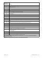
1.2.2
Auxiliary Fault Lamp
The auxiliary fault lamp flashes or lights continuously to
indicate different conditions. Figure 1-3 describes the
auxiliary fault lamp conditions.
Lamp Illumination
Generator Condition
Flashing
Continuous
Auxiliary Delay Shutdown. Lamp lights and the engine shuts down 5 seconds after high oil temperature
(P1-13), low coolant level (P1-10 [2-wire sender] or P1-14 [3-wire switch]), or auxiliary delay shutdown
(P1-15) faults (if equipped) occur. These fault conditions are inhibited during the first 30 seconds after crank
disconnect.
X
Auxiliary Immediate Shutdown. Lamp lights and the engine shuts down if activated by customer-supplied
sensing devices connected to auxiliary immediate shutdown ports (P1-17 and P1-18).
X
Emergency Stop Switch Reset. Lamp lights if the optional emergency stop switch is reset while the
generator set master switch is in the AUTO or RUN position. Place the generator set master switch in the
OFF/RESET position to clear this fault.
X
Low Fuel Shutdown (125RZG only). Lamp lights and the engine shuts down if activated by the low fuel
pressure shutdown switch connected to the Auxiliary Immediate Shutdown port P1-17. Place the generator
set master switch in the OFF/RESET position to clear this fault.
X
No AC Output. Lamp flashes if the controller senses no AC output with the unit running (except during first
10 seconds after startup). When the controller senses AC output, the flashing stops and the lamp is unlit.
Does not require manual reset.
X
Overvoltage Shutdown. Lamp lights and the engine shuts down immediately if an overvoltage condition
arises (if equipped with overvoltage shutdown kit).
X
Underfrequency Shutdown. Lamp lights and the engine shuts down if the engine speed drops below 5% of
the nominal engine speed (1710 for 1800 rpm or 1425 for 1500 rpm) for a continuous 60-second period.
X
Figure 1-3
1.2.3
Auxiliary Fault Lamp Operation
Fuses
The fuses listed in Figure 1-4 protect the generator set
circuitry.
Fuse
1.2.4
Analog Meters and Gauges
Figure 1-5 describes the meters and gauges located on
microprocessor controllers.
Description
F1
3-amp remote annunciator fuse protects the dry contact
kit (if equipped).
F2
3-amp controller fuse protects the controller circuit board,
speed sensor, and lamp circuit board.
F3
15-amp engine and accessories fuse protects
engine/starting circuitry and accessories.
Figure 1-4
Controller Fuses
Name
Description
AC voltmeter
Meter displays the AC output voltage. Use the
selector switch to choose the output lead
circuits.
AC ammeter
Meter displays the AC output amperage. Use
the selector switch to choose the phase
currents.
DC voltmeter
Meter displays the voltage of the starting
battery(ies).
Frequency
meter
Meter displays the frequency (Hz) of the
generator set output.
Hourmeter
Hourmeter records the generator set total
operating hours for reference in maintenance
scheduling.
Oil pressure
gauge
Gauge measures the engine oil pressure.
Scale lamps
(upper/lower)
Lamps indicate which AC voltmeter and/or
ammeter scales to read.
Water
temperature
gauge
Gauge displays the engine coolant
temperature.
Figure 1-5
TP-6161
1/08
Analog Meters and Gauges
Section 1 Specifications and Features
13
1.2.5
Switches and Controls
Figure 1-6 describes the switches and controls located
on microprocessor controllers.
Name
Description
Alarm horn
Horn sounds if any fault or prealarm condition
exists (except emergency stop, battery charger
fault, high battery voltage, or low battery voltage).
Place the generator set master switch in the
AUTO position before silencing the alarm horn.
See controller resetting procedure in Section
2.3.5, Controller Resetting After a Fault Shutdown.
Alarm
silence
switch
Emergency
stop switch
Switch silences the alarm during service. Place
the generator set master switch in the AUTO
position before silencing the alarm horn. To avoid
reactivating the alarm horn, restore all alarm horn
switches (controller, remote annunciator, and
audiovisual alarm) to their normal positions after
correcting the fault. See controller resetting
procedure in Section 2.3.5, Controller Resetting
After a Fault Shutdown.
Switch (if equipped) immediately shuts down the
generator set in emergency situations. Reset the
emergency stop switch after shutdown by pulling
the knob slightly outward. Use the emergency
stop switch for emergency shutdowns only. Use
the generator set master switch for normal
shutdowns. The local emergency stop switch is
standard on selected generator sets.
Generator
set master
switch
Switch functions as the controller reset and
generator set operation switch. Refer to
Section 2.3.1, Normal Operation, Section 2.3.2,
Prime Power Mode Operation, and Section 2.3.5,
Controller Resetting After a Fault Shutdown.
Lamp test
switch
Switch displays the controller indicator lamps.
Selector
switch
Switch selects the generator set output circuits to
measure. When switched to a position with three
circuit labels, the meters display the amperage on
the lead shown in the upper label and the voltage
between the two leads shown in the lower label.
The AC ammeter and voltmeter function only with
the switch in the ON position.
Voltage
adjustment
control, if
equipped
Control fine tunes (±5%) the generator set output
voltage. Used with 20--400 kW permanent
magnet/wound field alternator models only. The
voltage adjustment on 350--2000 kW pilot-excited
models is located in the generator junction box.
Figure 1-6
Switches and Controls
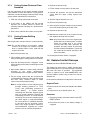
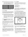
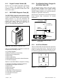
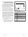
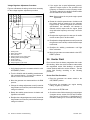
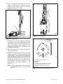
1.2.6
Terminal Strips
Two terminal strips are mounted on the controller circuit
board. See Figure 1-7 and Figure 1-8. Refer to Section
2.3.2, Prime Power Mode Operation, for information on
enabling prime power mode.
Terminal
Strip
Description
TB1/TB3
Terminal strip for connecting generator set
accessories such as an emergency stop switch, a
remote start/stop switch, audiovisual alarms, etc.
Refer to the wiring diagrams for information on
connecting accessories to the TB1 terminal strip.
TB2
Terminal strip for selecting the remote start/stop
switch inputs and prime power mode.
P3/P7
Communication module connection for remote serial
annunciator (RSA) or network communication.
P21
RS-485 communication connection for Modbusr to
download new application program software or for
connecting the remote serial annunciator.
P22
CAN (engine) communication connection.
Figure 1-7
Controller Terminal Strips/Connections
2
1
9
1.
2.
3.
4.
5.
6.
7.
8.
9.
8
7
6
5
3
4
GM28725-
TB1 (TB1A) terminal strip
TB3 (TB1B) terminal strip
TB2 terminal strip
P3 annunciator panel lamp and RSA communication
module connections
P21 for Modbusr RS-485 communication connection
P22 for CAN (engine) communication connection
SW1 DIP switch (8 positions)
P7 RSA communication module connection
Fuses
Figure 1-8
Controller DIP Switches
Modbusr is a registered trademark of Schneider Electric.
14
Section 1 Specifications and Features
TP-6161
1/08
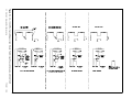
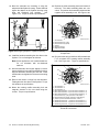
1.2.7
DIP Switches
The controller circuit board contains eight DIP switches,
see Figure 1-9.
Switch Position
DIP
Switch Description
1
Overspeed selection
Open
Closed
60 Hz
70 Hz
2
Temperature Cooldown
Enable
Cooldown
Disabled
Cooldown
Functional
3
Crank Mode Selection
Cyclic
Continuous
4
Engine Comm. Setting
5
Engine Comm. Setting
6
Modbusr Address Bit 0
See selections for
DIP switch
it h 4 and
d
DIP switch 5 below
Value = 0
Value = 2
7
Modbusr Address Bit 1
Value = 0
Value = 4
8
Modbusr Address Bit 2
Value = 0
Value = 8
4
5
4
5
4
5
MDEC Comm.
Isochronous
J1939 Communication
MDEC Comm.
Closed
5
Governor (VSG)
Closed
Figure 1-9
Engine Cranking (DIP Switch 3). The controller is
factory-set for cyclic cranking. To change to the
continuous cranking mode, use DIP switch 3.
Open
Closed
Open
Open
Closed
4
Engine Configuration (DIP Switches 4 and 5). See
Figure 1-9 for the DIP switch positions based on engine
configurations regarding non-ECM, MDEC, and J1939
engine communication selections.
DIP Switch Functions
Note: After setting DIP switches to the generator set
application, be sure to power down and then
power up the controller (disconnect the battery
and then reconnect the battery of the generator
set) or use the prime power switch, if equipped.
The controller will NOT acknowledge the DIP
switch change until after generator set controller
is powered up.
Push down the end of the DIP switch near the OPEN
label to open the switch, or push down the other end to
close it. See Figure 1-10.
1
Overspeed Frequency (DIP Switch 1). The generator
set overspeed frequency is set using DIP switch 1.
Select 70 Hz for 60 Hz voltages and 60 Hz for 50 Hz
voltages.
Temperature Cooldown (DIP Switch 2).
The
generator set will continue to run during a five-minute
cooldown cycle or shut down immediately. The choice is
made using DIP switch 2.
Open
No ECM
Typically, the factory default settings have all the DIP
switches in the closed position except the crank mode
selection switch SW3 which is open for cyclic cranking.
The overspeed selection switch SW1 is open on 50 Hz.
units. Be sure to select the correct DIP switch
configuration for each generator set application.
2 3 4 5 6 7 8
Modbusr Address (DIP Switches 6--8).
Each
Modbusr device requires a unique address. Address
numbers are created using a binary number system with
DIP switches 6--8. Figure 1-11 shows the DIP switch
position for each address number.
DIP Switches
Modbusr
Address
6
7
8
Value = 2
Value = 4
Value = 8
1
Open
Open
Open
3
Closed
Open
Open
5
Open
Closed
Open
7
Closed
Closed
Open
9
Open
Open
Closed
11
Closed
Open
Closed
13
Open
Closed
Closed
15
Closed
Closed
Closed
Figure 1-11 Modbusr Device Address
OPEN
1
6126
1. Push this side down to open circuit.
Figure 1-10 DIP Switch Open Position
Modbusr is a registered trademark of Schneider Electric.
TP-6161
1/08
Section 1 Specifications and Features
15
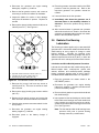
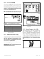
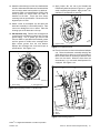
1.3 Expanded Decision-Maker 1 Controller
For identification of the expanded controller’s indicators
and controls and their functions, refer to Figure 1-12.
1
2
4
3
5
ADV-5849E-B
13
1.
2.
3.
4.
5.
6.
7.
12
11
Frequency meter
AC voltmeter
AC ammeter
Scale lamps (upper/lower)
Selector switch
Hourmeter
Generator set master switch
10
9
8.
9.
10.
11.
12.
13.
8
7
6
Voltage adjustment control
Fault lamp
10-amp controller fuse
DC voltmeter
Water temperature gauge
Oil pressure gauge
Figure 1-12 Expanded Decision-Makert1 Controller
Figure 1-13 and Figure 1-14 describe the controls and
indicators located on the controller.
Item
Description
Hourmeter
Hourmeter records the generator set total
operating hours for reference in
maintenance scheduling.
Item
Description
AC ammeter
Meter displays the AC output amperage. Use
the selector switch to choose the phase
currents.
Oil pressure gauge
Gauge displays the engine oil pressure.
Scale lamps
(upper/lower)
Lamps indicate which AC voltmeter
and/or ammeter scales to read.
AC voltmeter
Meter displays the AC output voltage. Use
the selector switch to choose the output lead
circuits.
Selector switch
DC voltmeter
Meter displays the voltage of the starting
battery(ies).
Fault lamp
Lamp illuminates during engine shutdown if
the engine shuts down because of one of the
following faults: high engine temperature, low
water level, low oil pressure, overcrank, or
overspeed. See Section 2.4.3, Fault
Shutdowns, for additional shutdown
information.
Switch selects the generator set output
circuits to measure. When switched to a
position with three circuit labels, the
meters display the amperage on the lead
shown in the upper label and the voltage
between the two leads shown in the
lower label. The AC ammeter and
voltmeter function only with the switch in
the ON position.
Voltage adjustment
control
Control fine tunes (±5%) the generator
set output voltage.
Water temperature
gauge
Gauge displays the engine coolant
temperature.
10-amp controller
fuse
Fuse protects the controller circuitry from
short circuits and overloads.
Frequency meter
Meter displays the frequency (Hz) of the
generator set output.
Generator set
master switch
Switch functions as the controller reset and
generator set operation switch.
Figure 1-14 Controls and Indicators, continued
Figure 1-13 Controls and Indicators
16
Section 1 Specifications and Features
TP-6161
1/08
Section 2 Operation
2.1 Prestart Checklist
To ensure continued satisfactory operation, perform the
following checks or inspections before or at each
startup, as designated, and at the intervals specified in
the service schedule. In addition, some checks require
verification after the unit starts.
Air Cleaner. Check for a clean and installed air cleaner
element to prevent unfiltered air from entering the
engine.
Battery. Check for tight battery connections. Consult
the battery manufacturer’s instructions regarding
battery care and maintenance.
Coolant Level. Check the coolant level according to
the cooling system maintenance information.
Ignition System. Ensure that the ends of all spark plug
wires are properly seated onto the coil/distributor and
the spark plug.
Lamp Test. Press the lamp test button, if equipped, to
verify that all controller LEDs illuminate.
Oil Level. Maintain the oil level at or near, not over, the
full mark on the dipstick. Keep the oil level in the
mechanical governor, if equipped, at or near the full
level.
Operating Area. Check for obstructions that could
block the flow of cooling air. Keep the air intake area
clean. Do not leave rags, tools, or debris on or near the
generator set.
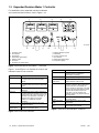
2.2 Generator Set Exercising
Note: Block heater damage. The block heater will fail
if the energized heater element is not immersed
in coolant. Fill the cooling system before turning
on the block heater. Run the engine until it is
warm, and refill the radiator to purge the air from
the system before energizing the block heater.
Operate the generator set under load once each week
for one hour. Perform the exercise in the presence of an
operator if the generator set does not have a
programmed exercise mode or an automatic transfer
switch with an exercise option.
Drive Belts. Check the belt condition and tension of the
radiator fan, water pump, and battery charging
alternator belt(s).
During the exercise period apply a minimum of 35% load
based on the nameplate standby rating, unless
otherwise instructed in the engine operation manual.
Exhaust System. Check for exhaust leaks and
blockages. Check the silencer and piping condition and
check for tight exhaust system connections.
The operator should perform all of the prestart checks
before starting the exercise procedure. Start the
generator set according to the starting procedure in the
controller section of this manual. While the generator
set is operating, listen for a smooth-running engine and
visually inspect the generator set for fluid or exhaust
leaks.
Inspect the exhaust system components (exhaust
manifold, exhaust line, flexible exhaust, clamps,
silencer, and outlet pipe) for cracks, leaks, and
corrosion.
D Check for corroded or broken metal parts and replace
2.3 16-Light Controller Features
them as needed.
D Check for loose, corroded, or missing clamps and
hangers. Tighten or replace the exhaust clamps and/
or hangers as needed.
D Check that the exhaust outlet is unobstructed.
D Visually inspect for exhaust leaks (blowby). Check
for carbon or soot residue on exhaust components.
Carbon and soot residue indicates an exhaust leak.
Seal leaks as needed.
2.3.1
Normal Operation
Local Starting. Move the generator set master switch
to the RUN position to start the generator set at the
controller.
Note: The alarm horn sounds and the Not in Auto lamp
lights when the generator set master switch is not
in the AUTO position.
Fuel Level. Check the fuel level and fill the tank(s)
regularly to ensure adequate fuel supply.
TP-6161
1/08
Section 2 Operation
17
Note: The transient start/stop function of the 16-light
controller prevents accidental cranking of the
rotating engine. If the generator set master
switch is momentarily placed in the OFF/RESET
position and then is returned to the RUN position,
the generator set slows to 750 rpm (25 Hz) and
recranks before returning to rated speed.
Automatic Starting. Move the generator set master
switch to the AUTO position to allow startup by an
automatic transfer switch or a remote start/stop switch.
Refer to the wiring diagrams for remote switch
connection information.
The engine cranks up to 30 seconds continuously or
75 seconds cyclically (crank 15 seconds, rest 15 seconds,
crank 15 seconds, etc.) before shutting down on an
overcrank fault.
Note: The engine ECM may limit the crank cycle even if
the controller is set to a longer time period.
Select the cyclic or continuous cranking mode on the
controller circuit board. See Section 1.2.7 DIP switches.
Stopping. Run the generator set without load for
5 minutes to ensure adequate engine cooldown. To
stop the generator set, place the generator set master
switch in the OFF/RESET position and wait until the
generator set stops completely.
Note: The generator set continues to run during a
5-minute cooldown cycle if a remote switch or
automatic transfer switch signals the engine to
stop.
Note: The controller circuit board DIP switches allow
disabling the engine cooldown function.
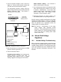
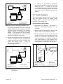
2.3.2
Prime Power Mode Operation
The controller can operate in either the normal mode or
the prime power mode. In prime power mode, the
controller draws less current when the generator set
master switch is in the OFF/RESET position, minimizing
the battery drain. Use the prime power mode for
installations that do not have a battery charger to help
prevent discharging the battery when the generator set
is not operating.
Moving the generator set master switch to the
OFF/RESET position disables all controller functions.
Moving the generator set master switch to the AUTO
position restores controller functions.
18
Section 2 Operation
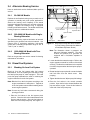
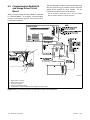
Enabling and Disabling the Prime Power Mode. To
enable the prime power mode, use jumpers to connect
TB2-1P to TB2-2P, TB2-3P to TB2-4P, and TB2-3 to
TB2-4. To deactivate the prime power mode, remove
these jumpers. See Figure 1-7, Figure 1-8, and
Figure 2-1.
Terminal
Purpose
1P
Prime power operation.
2P
Prime power operation.
3
Remote start ground. Connect transfer switch or
remote start switch to TB2--3 and TB2--4.
3P
Prime power operation.
4
Remote start. Connect transfer switch or remote
start switch to TB2--3 and TB2--4.
4P
Prime power operation.
Figure 2-1
16-Light Controller TB2 Terminal Strip
Prime Power Starting. The prime power mode
provides local starting only at the controller. The AUTO
position no longer functions as a remote start. When the
generator set master switch is in the OFF/RESET
position, the controller functions are inoperative. Move
the generator set master switch to the AUTO position to
start the generator set. Do not start the generator set
with the master switch in the RUN position because the
alarm horn will sound.
Note: Move the generator set master switch to the
AUTO position to return controller functions to
normal.
Prime Power Stopping. Move the generator set
master switch to the OFF/RESET position to stop the
generator set and power down the controller.
Note: The controller functions are inoperative when the
generator set master switch is in the OFF/RESET
position.
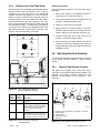
2.3.3
Emergency Stopping
Activate the controller emergency stop switch, if
equipped, or the optional remote emergency stop switch
for immediate shutdown.
Use the emergency stop switch(es) for emergency
shutdowns only. Use the generator set master switch for
normal shutdowns.
TP-6161
1/08
The unit shuts down and the controller emergency stop
lamp lights if an operator activates either the local or
remote emergency stop switch.
Use the following procedure to restart the generator set
after shutdown by an emergency stop switch. Refer to
Section 2.3.5, Controller Resetting After a Fault
Shutdown, to restart the generator set following a fault
shutdown.
Emergency Stop Switch Resetting Procedure
1. Investigate the cause of the emergency stop and
correct the circuit or wiring problem(s).
2. If the remote emergency stop switch was activated,
reset the switch by replacing the glass piece. If the
controller-mounted emergency stop switch (if
equipped) was activated, reset the controller
emergency stop switch by rotating the switch
clockwise until it springs back to its original position.
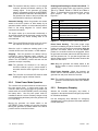
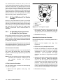
Fault
Description
High engine
temperature
The high engine temperature shutdown shuts
down the unit 5 seconds after a fault. The
shutdown does not function during the first
30 seconds following startup.
Note: The high temperature shutdown functions
only when the coolant level is in the operating
range.
Low coolant
level,
if equipped
The low coolant level shutdown shuts down the
unit 5 seconds after the fault. The shutdown
does not function during the first 30 seconds
following startup.
Low oil
pressure
The low oil pressure shutdown shuts down the
unit 5 seconds after fault detection. The
shutdown does not function during the first 30
seconds following startup.
Note: The low oil pressure shutdown does not
protect against low oil level. Check the oil level
at the engine.
Overcrank
Overcrank shuts down the unit after 45 seconds
of continuous cranking. Shutdown occurs after
75 seconds of cyclic cranking (crank 15
seconds, reset 15 seconds, crank 15 seconds,
etc., for a total of 75 seconds). Shutdown
occurs after 15 seconds if the engine or starter
does not turn (locked rotor).
Note: The controller has an automatic restart
function. The generator set attempts to restart if
the engine speed drops below 390 rpm (output
frequency of 13 Hz). Continued low engine
speed causes an overcrank fault condition.
Overspeed
Overspeed shuts down the unit immediately
when governed frequency on 50/60 Hz models
exceeds 60/70 Hz.
Note: The controller circuit board DIP switches
allow 50 Hz (60 Hz shutdown) or 60 Hz (70 Hz
shutdown) selection.
Overvoltage,if
equipped
Overvoltage shuts down the unit and lights the
auxiliary lamp when voltage is at least 15% over
the nominal voltage for longer than 2 seconds.
Note: Overvoltage can damage sensitive
equipment in less than 1 second. Provide
separate overvoltage protection for online
equipment requiring faster shutdowns.
Note: The controller auxiliary fault lamp lights if the
generator set master switch is in the RUN or
AUTO position during the resetting
procedure.
3. Toggle the generator set master switch to the
OFF/RESET position and then to the RUN or
AUTO position to restart the generator set. The
generator set does not crank until the resetting
procedure is completed.
2.3.4
Fault Shutdowns
The generator set shuts down automatically under the
fault conditions listed in Figure 2-2.
Figure 2-2
2.3.5
Controller Resetting After a Fault
Shutdown
Use the following procedure to restart the generator set
after a fault shutdown.
Refer to Section 2.3.3,
Emergency Stopping, to reset the generator set after an
emergency stop.
1. Move the controller alarm horn switch to the
SILENCE position. If equipped, the audiovisual
annunciator alarm horn and lamp are activated.
Move the audiovisual annunciator alarm switch to
SILENCE to stop the alarm horn. The audiovisual
annunciator lamp stays lit.
2. Disconnect the generator set from the load by
using the line circuit breaker or the automatic
transfer switch.
TP-6161
1/08
Fault Shutdowns
3. Correct the cause of fault shutdown. See the
Safety Precautions section of this manual before
proceeding.
4. Start the generator set by moving the generator set
master switch to the OFF/RESET position and then
to the RUN position. If equipped, the audiovisual
annunciator alarm horn sounds and lamp goes out.
5. Verify that the cause of the shutdown was
corrected by test operating the generator set.
6. Reconnect the generator set to the load by using
the line circuit breaker or the automatic transfer
switch.
Note: Place the generator set master switch in the
AUTO position before silencing the alarm
horn.
Section 2 Operation
19
7. Move the generator set master switch to the AUTO
position for startup by remote transfer switch or
remote start/stop switch. If equipped, move the
audiovisual annunciator alarm switch to NORMAL.
8. Move the controller alarm horn switch to the
NORMAL position.
2.4 Expanded Decision-Maker 1
Controller
2.4.1
Generator Set Starting
The fault lamp does not stay lit after the generator set
shuts down on a fault condition.
2.4.4
Controller Resetting After a Fault
Shutdown
Use the following procedure to restart the generator set
after a fault shutdown.
1. Disconnect the generator set from the load using
the line circuit breaker or automatic transfer switch.
See the Safety Precautions at the beginning of this
section before proceeding.
Local Starting. Move the generator set to the RUN
position to immediately start the generator set.
2. Correct the cause of the fault shutdown. See the
Safety Precautions at the beginning of this section
before proceeding.
Automatic Starting. Move the generator set master
switch to the AUTO position to allow startup by the
automatic transfer switch or the remote start/stop switch
connected to controller terminals TB1-3 and TB1-4.
3. Start the generator set by moving the generator set
master switch to RESET/OFF and then to RUN.
Note: The controller allows up to 30 seconds of
continuous cranking before overcrank shutdown
occurs.
Note: The engine ECM may limit the crank cycle even if
the controller is set to a longer time period.
2.4.2
Generator Set Stopping
Local Stopping
1. Run the generator set at no load for 5 minutes to
ensure adequate engine cooldown.
2. Move the generator set master switch to the
OFF/RESET position. The engine stops.
Automatic Stopping
1. The automatic transfer switch (ATS) or other
device disconnects the load from the generator set.
2. The generator set continues to run for a preset time
if the ATS is equipped with an engine cooldown
time delay.
3. The ATS opens the connection between controller
terminals TB1-3 and TB1-4. The generator set
shuts down if the generator set master switch is in
the AUTO position.
2.4.3
4. Verify that the cause of the shutdown has been
corrected by test operating the generator set.
5. Reconnect the generator set to the load using the
line circuit breaker or automatic transfer switch.
6. Move the generator set master switch to the AUTO
position for startup by remote transfer switch or
remote start/stop switch.
Fault
Description
High engine
temperature
Shutdown occurs 5 seconds after the fault. The
high engine temperature shutdown does not
function during the first 5 seconds after startup.
Note: The high temperature shutdown functions
only when the coolant level is in the operating
range.
Low coolant
level
Shutdown occurs 5 seconds after the fault. The
low coolant level shutdown does not function
during the first 5 seconds after startup.
Low oil
pressure
Shutdown occurs 5 seconds after the fault. The
low oil pressure shutdown does not function
during the first 5 seconds after startup.
Note: The low oil pressure shutdown does not
protect against low oil level. Check the oil level at
the engine.
Overcrank
Shutdown occurs after 30 seconds of continuous
cranking. Shutdown occurs 30 seconds after
startup if there is no AC output.
Overspeed
Shutdown occurs immediately when the governed
frequency on the 50 and 60 Hz models exceeds
70 Hz.
Figure 2-3
Fault Shutdowns
Fault Shutdowns
The generator set shuts down automatically under the
fault conditions shown in Figure 2-3 and cannot be
restarted until the fault condition is corrected. Reset the
controller after a fault shutdown.
20
Section 2 Operation
TP-6161
1/08
Section 3 Scheduled Maintenance
Under normal operating conditions, the generator set’s
alternator requires no normal service. Consult the
prestart checklist in Section 2.1 for a list of routine
checks.
3.1 Alternator Service
When operating the generator set under dusty or dirty
conditions, use dry compressed air to blow dust out of
the alternator while the generator set is running. Direct
the stream of air through openings in the generator set
end bracket.
Disabling the generator set. Accidental starting can
cause severe injury or death. Before working on the
generator set or connected equipment, disable the generator
set as follows: (1) Move the generator set master switch to the
OFF position. (2) Disconnect the power to the battery charger.
(3) Remove the battery cables, negative (--) lead first.
Reconnect the negative (--) lead last when reconnecting the
battery. Follow these precautions to prevent starting of the
generator set by an automatic transfer switch, remote
start/stop switch, or engine start command from a remote
computer.
WARNING
3.2 Engine Service
Perform engine service at the intervals specified in the
engine manufacturer’s service literature. Contact an
authorized service distributor/dealer to obtain service
literature.
Note: Have maintenance work, including battery
service, performed by appropriately skilled and
suitably trained maintenance personnel familiar
with generator set operation and service.
WARNING
Accidental starting.
Can cause severe injury or death.
Disconnect the battery cables before
working on the generator set.
Remove the negative (--) lead first
when disconnecting the battery.
Reconnect the negative (--) lead last
when reconnecting the battery.
TP-6161
1/08
Hot engine and exhaust system.
Can cause severe injury or death.
Do not work on the generator set until
it cools.
Servicing the exhaust system. Hot parts can cause
severe injury or death. Do not touch hot engine parts. The
engine and exhaust system components become extremely
hot during operation.
WARNING
Hazardous voltage. Moving parts.
Can cause severe injury or death.
Operate the generator set only when
all guards and electrical enclosures
are in place.
Servicing the generator set when it is operating. Exposed
moving parts can cause severe injury or death. Keep
hands, feet, hair, clothing, and test leads away from the belts
and pulleys when the generator set is running. Replace
guards, screens, and covers before operating the generator
set.
Section 3 Scheduled Maintenance
21
3.3 Service Schedule
Action
System—Component
Visually Inspect
Check
Day tank level
X
X
Flexible lines and connections
X
Fuel level switch
X
Change
Clean
Test
Interval
Fuel
Main tank supply level
Weekly
R
Weekly
X
X
Solenoid valve operation
X
Transfer pump operation
X
Weekly
D
Water in system, remove
Weekly
X
Weekly
X
Weekly
D
Weekly
Filter(s)
D
Quarterly
Gasoline supply
R
Six Months
Fuel piping
X
Tank vents and return lines for obstructions
Yearly
X
Yearly
Lubrication
Oil level
D
Crankcase breather
D
D
Weekly
D
Change oil
D
Replace filter(s)*
D
Quarterly
First 50 Hours, Then
Every 250 Hours
Cooling
Radiator fan bolt torque
(1500--2800REOZDC with unit-mounted radiator)
X
Initially 8 Hours, Then
Every 100 Hours
Air cleaner to room/enclosure
X
Weekly
Block heater operation
X
Weekly
Coolant level
D
D
Weekly
Flexible hoses and connectors
X
X
Weekly
Water pump(s)
D
Fan and alternator belts
D
Weekly
D
R
Monthly
D
Coolant temperature protection level
Lubricate fan bearings (1200--2000 kW)
X
Air ducts, louvers
200 Hours or
Six Months
X
X
X
Heat exchanger
Louver motors and controls
Yearly
D
Coolant
Yearly
X
X
X
Radiator exterior
Yearly
X
X
Water supply to heat exchanger
Six Months
Yearly
Yearly
X
Yearly
X
Weekly
X
Weekly
Exhaust Line
Drain condensate trap
Leakage
X
Insulation, fire hazards
X
Flexible connector(s)
X
Quarterly
Six Months
Excessive back pressure
Hangers and supports
X
X
Yearly
Yearly
DC Electrical System
Battery charger operation, charge rate
X
Battery electrolyte level
Monthly
X
Monthly
Battery specific gravity, charge state
X
Recharge after engine start
X
Remove corrosion, clean and dry battery and rack
X
Clean and tighten battery terminals
X
Tighten DC electrical connections
Monthly
Monthly
X
Monthly
X
Quarterly
X
Six Months
D Follow procedures and frequencies indicated in the engine manufacturer’s maintenance manual.
If not indicated, follow this service schedule. Some items may not apply to all generator sets.
R Replace as necessary.
X Action
* Service more frequently if operated in dusty areas.
22
Section 3 Scheduled Maintenance
TP-6161
1/08
Service Schedule, continued
Action
System—Component
Visually Inspect
Check
Change
Clean
Test
Interval
R
Weekly
AC Electrical System
Controller lamp test
X
General Inspection
X
Circuit breakers, fuses[
X
X
Wire abrasions where subject to motion
X
X
Weekly
Safety and alarm operation
X
Tighten control and power wiring connections
X
Transfer switch main contacts[
X
X
Monthly
Quarterly
X
Six Months
Yearly
X
X
D
Voltage-sensing device/relay adjustment[
Wire-cable insulation breakdown
R
X
Yearly
D
Yearly
X
3 Years or 500 Hours
Engine and Mounting
General inspection
D
Governor operation, lubricate moving parts
D
Weekly
D
Air cleaner service
D
Choke, carburetor adjustment
D
Governor oil (mechanical governor only)
D
Ignition components
Monthly
D
Six Months
Six Months
Yearly
D
D
Injector pump and injector flow rate, pressure,
spray pattern
D
Valve clearance
D
Bolt torque
D
Yearly
D
Yearly
3 Years or 500 Hours
D
3 Years or 500 Hours
Remote Control System, etc.
Compartment condition
X
X
Weekly
Remote control
X
Monthly
Run generator set
X
Monthly
Alternator
General inspection
X
Rotor and stator
X
Weekly
Bearing condition
X
X
Exciter
X
X
X
Yearly
Voltage regulator
X
X
X
Yearly
X
Yearly
Measure and record resistance readings of
windings with insulation tester (Meggerr, with
SCR assembly or rectifier disconnected)
Blow dust out of alternator*
Yearly
R
X
X
Yearly
D
2 Years or 300 Hours
X
Weekly
General Condition of Equipment
Any condition of vibration, leakage, noise,
temperature, or deterioration
X
Ensure that system is set for automatic operation
X
Interior of equipment room or outdoor weather
housing
X
X
Weekly
X
Weekly
D Follow procedures and frequencies indicated in the engine manufacturer’s maintenance manual.
If not indicated, follow this service schedule. Some items may not apply to all generator sets.
R Replace as necessary.
X Action.
* Service more frequently if operated in dusty areas.
[ Do not break manufacturer’s seals or internally inspect these devices.
Meggerr is a registered trademark of Biddle Instruments.
TP-6161
1/08
Section 3 Scheduled Maintenance
23
3.4 Alternator Bearing Service
Have an authorized service distributor/dealer perform
service.
3.4.1
20--300 kW Models
Replace the end bracket bearing every 10,000 hours of
operation in standby and prime power applications.
Service the bearing more frequently if the annual
inspection indicates excessive rotor end play or bearing
damage. Replace the tolerance ring, if equipped,
following end bracket removal. The sealed end bracket
bearing requires no additional lubrication.
Close this Valve
Open this Valve
Open this Valve
3.4.2
350--2000 kW Models with SingleBearing Alternator
The alternator bearing requires lubrication at intervals
specified in the generator set technical manual. Use
Chevron SRI or equivalent antifriction, high-quality
grease with a lubrication temperature range of --30° to
+175°C (--22° to +350°F).
3.4.3
1250--2000 kW Model with TwoBearing Alternator
Refer to the generator set service manual for bearing
maintenance information.
3.5 Diesel Fuel Systems
3.5.1
Bleeding Air from Fuel System
Valve Open
Figure 3-1
Valve Closed
PK-272000-H
Hand Prime Pump with Valve Positions
for Fuel Priming (Generator Set Without
a Fuel/Water Separator Shown)
Note: The illustration shows a generator set
without a fuel/water separator. The valve
location and position for a generator set
equipped with a fuel/water separator is
similar.
2. Loosen the bleed screw at the engine. Refer to the
engine operation manual for location of the bleed
screw(s). The bleed screw allows air to be expelled
from the fuel system when the hand prime pump is
operated.
Bleed air from the fuel system after fuel system
maintenance, such as replacing the fuel filter(s) using
the hand prime pump kit, when equipped. The hand
prime fuel pump eliminates the need for cranking the
engine to bleed air from the fuel system.
3. Rotate hand prime pump handle counterclockwise
until fuel flows from the bleed screw. Stop
pumping.
Note: Bleed air from the fuel system according to the
engine manufacturer’s instructions. Trapped air
in the fuel system causes difficult starting and/or
erratic engine operation.
5. Place the fuel valves in the normal operation
position. Open the fuel valve located between the
pipe tee and the engine. Close the fuel valves on
each side of the fuel prime pump.
4. Tighten the bleed screw. Wipe up any fuel leakage.
Note: Correct any fuel leaks encountered during the
priming procedure.
1. Place the fuel valves in the fuel system prime
position. Close the fuel valve located between the
pipe tee and the engine. Open the fuel valves on
each side of the fuel prime pump. See Figure 3-1.
24
Section 3 Scheduled Maintenance
TP-6161
1/08
3.5.2
Subbase Inner Fuel Tank Alarm
This kit provides for both audible and visual alarm from a
location remote from the generator set if a leak is
detected in the inner fuel tank of the double-wall
subbase fuel tanks. See Figure 3-2. If the inner tank is
leaking, a sensor installed in the outer tank sends an
electrical signal to the alarm plate when the sensor
becomes immersed in the fuel collecting in the outer
tank. If a leak is detected, the alarm horn will sound and
the fault lamp will light. The alarm horn is quieted by
moving the alarm switch to the SILENCE position; the
alarm lamp remains lit until the fault is corrected. See
Figure 3-3 for troubleshooting information.
Resetting Procedure
Use the following procedure to reset the alarm after a
fault alarm.
1. Move alarm switch to the SILENCE position to
stop alarm horn. Lamp will remain lit.
2. Disconnect generator set from load with line circuit
breaker or automatic transfer switch.
3. Repair or replace the inner fuel tank.
4. Move generator set master switch to the OFF/
RESET position and then to the RUN position for
startup. Alarm horn sounds and lamp goes out.
5. Reconnect generator set to load via line circuit
breaker or automatic transfer switch.
Inner Tank
6. Move generator set master switch to the AUTO
position for startup by remote transfer switch or
remote start/stop switch. Move alarm switch to the
NORMAL position.
Fuel Leak
Alarm
Alarm
Normal
Silence
3.6 Gas/Gasoline Fuel Systems
Leak Alarm Panel
This section describes fuel systems that are not covered
in the engine operation manual or engine service
manual.
3.6.1
Gaseous Fuel System Concept
The gaseous fuel system uses a fuel valve with a
solenoid to control the fuel flow to the fuel regulator. The
generator set-mounted regulator reduces the fuel
pressure as fuel passes to the carburetor. See
Figure 3-4.
1
FF-273000-D
Figure 3-2
Float
Switch
Position
Normal
Open
The alarm horn and the lamp are not
energized.
Normal
Closed
The alarm horn and lamp activate when a
fuel leak occurs. If the alarm switch is
moved to the silence position the lamp
stays on until the fuel leak fault is
corrected.
Open
Figure 3-3
TP-6161
3
4
5
Inner Fuel Tank Leak Alarm
(20--300 kW Model Shown)
Alarm
Switch
Position
Silence
2
Observation
The alarm horn sounds to alert the user
that the alarm horn switch is not in the
normal position and that the alarm horn
will not sound should a fuel leak occur.
Inner Fuel Tank Leak Alarm
Troubleshooting
1/08
TP-5750-3
1.
2.
3.
4.
5.
Primary regulator (supplied by gas supplier or customer)
Pressure gauge
Solenoid valve
Secondary regulator
Carburetor
Figure 3-4
Fuel Regulator and Valve, Typical
Section 3 Scheduled Maintenance
25
The carburetor/mixer controls the ratio of fuel to air
under varying load and speed conditions. Because the
carburetor receives fuel in a gaseous state, it does not
have to vaporize the fuel. When switching from natural
gas to LP gas or LP gas to natural gas, verify that the
electronic governor maintains the rated engine speed
(1800 rpm at 60 Hz or 1500 rpm at 50 Hz). If the engine
speed is incorrect, refer to the generator set service
manual for the governor adjustment procedure.
3.6.2
2
LP Liquid Withdrawal Fuel System
Concept
With the LP liquid withdrawal fuel system, pressurized
liquid LP fuel passes from the tank to a vaporizer. The
vaporizer converts the liquid fuel to gas before sending it
to the carburetor. The system also includes a fuel valve
that shuts off the fuel flow when the engine stops.
Contact an authorized service distributor/dealer for
availability.
3.6.3
1
LP Gas/Natural Gas Conversion
for Straight Gas Fuel System
4
3
SB-527
1.
2.
3.
4.
Fuel regulator
Spring
Adjustment screw
Cover plug
Figure 3-5
Fuel Regulator, Typical
2. Remove the adjustment screw and spring from the
fuel regulator. Save the adjustment screw and
spring for possible conversion back to natural gas.
3. Reinstall the cover plug.
Most models operate on either LP gas or natural gas fuel
by performing the fuel conversion procedure. Some
models require a different fuel kit when changing gas
fuels. Consult your local generator set distributor/dealer
for additional information.
Fuel conversion may decrease generator set output and
affect exhaust emissions. Consult your local generator
set distributor/dealer for additional information.
Natural Gas Fuel Conversion Procedure
Use the following steps to convert the generator set to
natural gas:
1. Remove the fuel regulator cover plug.
Figure 3-5.
See
2. Replace the spring and adjustment screw.
Fuel Conversion Procedure
When converting the generator set to operate with LP
gas, remove the internal spring from the secondary
regulator. Install the spring to operate the generator set
on natural gas.
Note: Not all fuel regulators require spring and retainer
removal for fuel conversion. A hang tag on the
fuel regulator identifies the conversion
procedure.
LP Fuel Conversion Procedure
Use the following steps to remove the internal spring
from the fuel regulator:
1. Remove the fuel regulator cover plug.
Figure 3-5.
26
Section 3 Scheduled Maintenance
See
3. Connect a manometer to check the fuel supply
pressure on the carburetor side of the regulator
downstream of any fuel system equipment
accessories. The recommended fuel supply
pressures are shown on the generator set spec
sheet.
4. Adjust the fuel supply pressure with the generator
set running at full load. Rotate the adjustment
screw on the fuel regulator until the pressure
indicated by the manometer matches the specified
pressure. Use the lower pressure value if the
generator set still provides good response and full
power. Lower-than-specified pressures may result
in poor response to load changes or lack of power.
5. Reinstall the cover plug.
TP-6161
1/08
3.6.4
Fuel System Changeover Kits
Automatic Changeover
A changeover fuel system kit provides automatic
changeover from natural gas to LP gas vapor or from
LP gas vapor to natural gas. The primary and backup
fuels each have a secondary fuel regulator and a fuel
valve. Typically, the primary fuel is natural gas; the
backup fuel is LP gas vapor. When the generator set
starts, the primary fuel valve opens and the backup fuel
valve closes. The primary fuel line has a vacuum
switch in series with a relay connected to the start/run
circuit. When the primary fuel pressure drops below
0.6 kPa (1.4 oz./in.2) or 6.4 cm (2.5 in.) water column , a
relay opens the backup fuel valve and closes the
primary fuel valve. When the primary fuel pressure
rises above 0.6 kPa (1.4 oz./in.2) or 6.4 cm (2.5 in.)
water column, the generator set uses the primary fuel.
Contact an authorized service distributor/dealer for kit
availability.
Gasoline Carburetor Adjustment
Refer to the engine operation manual or engine service
manual for gasoline carburetor adjustment information.
Gaseous Carburetor (Fuel Mixer) Adjustment
Procedure
Use the following procedure to adjust the carburetor
(fuel mixer).
1. Start the generator set and run it at approximately
half load.
2. Adjust the engine fuel mixture screw (Figure 3-6)
until the engine runs smoothly.
3. Apply varying loads and readjust the carburetor as
necessary to achieve smooth engine performance
at all load levels.
4. Stop the generator set.
Manual Changeover
A manual changeover fuel system allows manual
changeover from gasoline to natural gas or LP gas, or
from natural gas or LP gas to gasoline. Typically, the
combination system uses gas as the primary, preferred
fuel and gasoline in emergencies. If the primary fuel is
unavailable (an empty fuel tank or fuel supply disruption),
the system uses gasoline. A toggle switch on the
generator set controls the fuel choice and energizes
either a fuel solenoid and electric fuel pump for gasoline
or a fuel valve for gas. Pull out the control cable for
gasoline and push in the control cable for gas.
Figure 3-6
3.6.5
3.6.6
Carburetor Adjustment
Before adjusting the carburetor, verify that the engine
compression and ignition system meet specifications.
Do not adjust the carburetor to compensate for other
engine disorders. If the engine speed is incorrect, adjust
the electronic governor to achieve 1800 rpm (at 60 Hz)
or 1500 rpm (at 50 Hz). Adjust the carburetor if governor
adjustment alone does not result in the desired engine
speed.
Adjusting the carburetor affects the engine fuel mixture.
Routine carburetor adjustment is not necessary.
However, if the carburetor is removed or tampered with,
the carburetor may require adjustment to achieve
optimum engine performance. Some engines have
sealed carburetors that are not adjustable.
TP-6161
1/08
2
1
3
TP-5750-3
1. Fuel adjusting screw
2. Lean
3. Rich
Fuel Mixture Adjustment, Typical
Fuel System Maintenance
Gasoline Models
Clean or replace the fuel filter at the specified interval.
Service the filters more frequently if the engine runs
roughly, as a clogged fuel filter can cause rough engine
operation. Some models use a disposable inline fuel
filter, which must be replaced. Other models have a fuel
pump with an integral fuel filter that requires cleaning at
the specified interval.
Gaseous Models
This fuel system requires no regular maintenance.
Section 3 Scheduled Maintenance
27
3.7 Cooling System
The cooling system maintenance information applies to
radiator-cooled models and city-water-cooled (heat
exchanger) models. The cooling systems function
similarly even though they use different components.
Radiator-cooled models have a radiator with a pressure
cap and coolant recovery tank. City-water-cooled
models have a heat exchanger and an expansion/surge
tank with a pressure cap.
WARNING
3.7.2
Cooling System Component
Inspection
To prevent generator set shutdown or damage caused
by overheating:
D Keep the cooling air inlets clean and unobstructed.
D Inspect the radiator’s exterior for obstructions.
Remove dirt and foreign material using a soft brush or
cloth to avoid damaging the radiator fins.
D Check the hoses and connections for leaks. Replace
any cracked, frayed, or spongy hoses.
D Check the condition and tension of the radiator fan
Hot coolant and steam.
Can cause severe injury or death.
Before removing the pressure cap,
stop the generator set and allow it to
cool. Then loosen the pressure cap
to relieve pressure.
Allow the engine to cool. Release pressure from the
cooling system before removing the pressure cap. To
release pressure, cover the pressure cap with a thick
cloth and then slowly turn the cap counterclockwise to
the first stop. Remove the cap after pressure has been
completely released and the engine has cooled. Check
the coolant level at the tank if the generator set has a
coolant recovery tank.
Note: Engine damage. Bleed the air from the cooling
system to prevent overheating and subsequent
engine damage.
Note: Block heater damage. The block heater will fail
if the energized heater element is not immersed
in coolant. Fill the cooling system before turning
on the block heater. Run the engine until it is
warm, and refill the radiator to purge the air from
the system before energizing the block heater.
3.7.1
Coolant Level Check
Check the coolant level in the coolant recovery tank, if
equipped. Maintain the coolant level between the high
and low marks.
Note: Periodically check the coolant level by removing
the pressure cap. Do not rely solely on the level in
the coolant recovery tank. Add fresh coolant until
the level is just below the overflow tube opening
of the filler neck.
28
Section 3 Scheduled Maintenance
and water pump belt(s). Follow the belt tension
procedure in this manual and/or the engine operation
manual.
D Check the pressure cap seal and replace a cracked or
deteriorated cap. Remove dirt and other debris from
the pressure cap and filler neck. The pressure cap
raises the boiling point of the coolant, enabling higher
operating temperatures. Replace a leaking pressure
cap with one rated for the same pressure. The
pressure cap rating usually appears on the pressure
cap.
3.7.3
Cooling System Drainage
Procedure
For optimum protection, drain, flush, and refill the
cooling system at the intervals listed in the service
schedule.
Note: Dispose of all waste materials (oil, fuel, coolant,
filters, and gaskets) in an environmentally safe
manner.
1. Deenergize the block heater, if equipped.
2. Remove the pressure cap to allow the entire
system to drain and prevent air pockets from
restricting coolant flow through the engine block.
3. Open the radiator and/or engine block coolant
drain valve(s) and allow the system to drain.
4. If the inside of the radiator has mineral deposits or
the used coolant contains dirt or grease, refer to
Section 3.7.4, Cooling System Flush and Clean
Procedure. If the cooling system does not have
mineral deposits, go to Section 3.7.5, Cooling
System Refilling Procedure.
TP-6161
1/08
3.7.4
Cooling System Flush and Clean
Procedure
Use the instructions in the engine operation manual
when available to flush and clean the cooling system.
Otherwise, use the following procedure and the cooling
system cleaner manufacturer’s instructions.
1. Flush the cooling system with clean water.
2. If the inside of the radiator still has mineral
deposits, use a radiator cleaner to remove the
remaining deposits following the manufacturer’s
instructions.
3. Drain, clean, and flush the coolant recovery tank.
3.7.5
Cooling System Refilling
Procedure
See the generator set spec sheet for coolant capacity.
Note: Do not add coolant to a hot engine. Adding
coolant to a hot engine can cause the cylinder
block or cylinder head to crack. Wait until the
engine has cooled.
6. Replace the pressure cap.
7. Fill the coolant recovery tank to the low mark.
8. Operate the generator set until the thermostat
opens when the upper cooling system hose
warms.
9. Stop the engine and allow it to cool.
10. Remove the pressure cap.
11. Add coolant to bring the coolant level to just below
the overflow tube opening of the filler neck.
12. Replace the pressure cap.
13. Maintain the coolant level in the coolant recovery
tank between the high and low marks.
Note: Air pockets often form in the engine water
jacket when the coolant system is refilled.
Check the coolant level in the coolant
recovery tank after each generator set
operation and add coolant as necessary
until the coolant level stabilizes. Then check
the coolant at the interval specified in the
service schedule.
1. Remove the pressure cap.
14. Reenergize the block heater, if equipped.
2. Close radiator and/or engine block coolant drain
valve(s) and tighten cooling system hose clamps.
3. Open the air-bleed petcocks, if equipped. Close
the air-bleed petcocks when coolant begins to flow
from them.
4. Add coolant additives or water pump lubricants
according to the engine manufacturer’s
recommendations in the engine operation manual.
5. Fill the cooling system with the recommended
coolant/antifreeze mixture of 50% ethylene glycol
and 50% clean, softened water to inhibit
rust/corrosion and prevent freezing.
Note: A coolant solution of 50% ethylene glycol
provides freezing protection to --37°C
(--34°F) and overheating protection to
129°C (265°F).
A coolant solution
containing less than 50% ethylene glycol
may not provide adequate freezing and
overheating protection. A coolant solution
containing more than 50% ethylene glycol
can cause engine or component damage.
Do not use alcohol or methanol antifreeze
or mix them with the specified coolant.
Refer to the engine operation manual for
recommendations regarding the coolant
mixture to use in extreme temperatures.
TP-6161
1/08
3.8 Radiator Fan Bolt Retorque
Adapted from Service Bulletin SB-683 12/07a.
The radiator fan bolts must be initially checked after
approximately 8 hours of operation and then rechecked
after each 100 hours of operation. This scheduled
service is required on all 1500--2800REOZDC unitmounted radiator models using a 2743 mm (108 in.)
diameter fan.
Perform the scheduled service steps in the order shown.
Required Tools
D Socket wrench sets American Standard and Metric
sizes
D Torque wrench, up to 203 Nm (150 ft. lb.)
Procedure
1. Place the generator set master switch in the OFF/
RESET position.
2. Disconnect the power to the battery charger, if
equipped.
Section 3 Scheduled Maintenance
29
3. Disconnect the generator set engine starting
battery(ies), negative (--) lead first.
4. Remove the fan guards, screens, and covers as
necessary to access the radiator fan hardware.
13. Place the generator set master switch to the RUN
position to start the generator set. Refer to the
respective generator set operation manual as
needed.
14. Listen and observe the fan operation.
5. Inspect the blades for cracks or other damage.
Verify that all hardware is present. Replace as
needed.
6. Retorque the (32 qty.) blade retention bolts/nuts to
136 Nm (100 ft. lb.). See Figure 3-7.
15. Immediately shut down the generator set if
abnormal noise or fan assembly vibration is
observed. Correct the problem and go back to
step 13.
16. After several minutes of generator set operation
without abnormal noise or vibration, shut down the
generator set by placing the generator set master
switch to the OFF/RESET position.
5
4
6
3.9 Radiator Fan Bearing
Lubrication
The following procedure applies only to 1200--2000 kW
generator sets. Lubricate the radiator fan shaft and idler
shaft bearings at every engine oil change to avoid
bearing damage.
Lubricate the bearings every
200 hours of operation when the generator set runs in
ambient temperatures below 29°C (85°F) or when the
generator set runs in a dusty and/or humid environment.
Lubrication and Drive Belt Adjustment Procedure
SECTION A-- A
GM18401-J
4. (32) blade retention bolts/nuts, 136 Nm (100 ft. lb.)
5. (12) hub boss cap screws, 102 Nm (75 ft. lb.)
6. (3) bushing cap screws, 43 Nm (32 ft. lb.)
Figure 3-7
Fan Hardware Location and Torque
Lubricate the fan shaft and idler shaft bearings with a
lithium-complex base, multi-purpose grease with
antirust, antifoam, and extreme-pressure additives
having a minimum dropping point of 204°C (400°F).
Use Mobil Mobilith AW2 NLGI Grade 2 or equivalent.
1. Place the generator set master switch in the
OFF/RESET position.
7. Retorque the (12 qty.) hub boss cap screws to
102 Nm (75 ft. lb.). There are six screws on each
side of the fan.
2. Disconnect the generator set engine starting
battery(ies), negative (--) lead first, and disconnect
power to the battery charger.
8. Retorque the (3 qty.) bushing cap screws to 43 Nm
(32 ft. lb.).
3. Remove the belt guards to expose the fan shaft and
idler shaft bearings.
9. Replace the fan guards, screens, and covers that
were removed to access the radiator fan hardware.
4. Inject grease into the two bearings on the fan shaft
block and the two bearings on the idler shaft block
using a grease gun until a 3--6 mm (0.13--0.25 in.)
grease column shows at the bearing pressure relief
port. See Figure 3-8.
10. Check that the generator set master switch is in the
OFF position.
11. Reconnect the generator set engine starting
battery, negative (--) lead last.
12. Reconnect power to the battery charger, if
equipped.
30
Section 3 Scheduled Maintenance
Note: The fan shaft and idler shaft bearings have
pressure relief ports to prevent bearing
damage caused by overlubrication.
TP-6161
1/08
3.10 Battery
1
WARNING
5
2
Sulfuric acid in batteries.
Can cause severe injury or death.
Wear protective goggles and
clothing. Battery acid may cause
blindness and burn skin.
4
2
3
TP-5353-3
1
1. Grease fittings
2. Pressure relief port
3. Radiator assembly
Figure 3-8
4. Idler shaft grease fittings
5. Fan shaft grease fittings
Radiator Fan Bearings and Pressure
Relief Ports, Typical
5. Remove excess grease from the bearing pressure
relief ports.
6. Inspect the fan drive belt and replace if it is damaged
or worn. Check the fan belt tension using a poly
V-belt tension gauge and adjust the tension, if
necessary. See Figure 3-9.
Generator Set Model
1200-2000 kW
New Belt,
N (lbf.)
Used Belt,*
N (lbf.)
2450--2890
(550--650)
1650--1910
(370--430)
* A belt is considered used after 50 hours of service.
Figure 3-9
Poly V-Belt Tension Specifications
7. Reinstall the belt guards using the original
hardware.
8. Reconnect the generator set engine starting
battery(ies), negative (--) lead last.
9. Test run the generator set for a few minutes and
listen for belt noise (squeal) indicating a slipping
belt. Stop the generator set.
If the belt slips after the belt tension procedure, clean the
pulley surfaces and repeat the belt tension procedure. If
slippage continues, replace the fan belt.
TP-6161
1/08
Battery gases. Explosion can cause severe injury or
death. Battery gases can cause an explosion. Do not smoke
or permit flames or sparks to occur near a battery at any time,
particularly when it is charging. Do not dispose of a battery in a
fire. To prevent burns and sparks that could cause an
explosion, avoid touching the battery terminals with tools or
other metal objects. Remove all jewelry before servicing the
equipment. Discharge static electricity from your body before
touching batteries by first touching a grounded metal surface
away from the battery. To avoid sparks, do not disturb the
battery charger connections while the battery is charging.
Always turn the battery charger off before disconnecting the
battery connections. Ventilate the compartments containing
batteries to prevent accumulation of explosive gases.
Battery short circuits. Explosion can cause severe injury
or death. Short circuits can cause bodily injury and/or
equipment damage. Disconnect the battery before generator
set installation or maintenance. Remove all jewelry before
servicing the equipment. Use tools with insulated handles.
Remove the negative (--) lead first when disconnecting the
battery.
Reconnect the negative (--) lead last when
reconnecting the battery. Never connect the negative (--)
battery cable to the positive (+) connection terminal of the
starter solenoid. Do not test the battery condition by shorting
the terminals together.
Battery electrolyte is a diluted sulfuric acid. Battery acid
can cause severe injury or death. Battery acid can cause
blindness and burn skin. Always wear splashproof safety
goggles, rubber gloves, and boots when servicing the battery.
Do not open a sealed battery or mutilate the battery case. If
battery acid splashes in the eyes or on the skin, immediately
flush the affected area for 15 minutes with large quantities of
clean water. Seek immediate medical aid in the case of eye
contact. Never add acid to a battery after placing the battery in
service, as this may result in hazardous spattering of battery
acid.
Battery acid cleanup. Battery acid can cause severe
injury or death. Battery acid is electrically conductive and
corrosive. Add 500 g (1 lb.) of bicarbonate of soda (baking
soda) to a container with 4 L (1 gal.) of water and mix the
neutralizing solution. Pour the neutralizing solution on the
spilled battery acid and continue to add the neutralizing
solution to the spilled battery acid until all evidence of a
chemical reaction (foaming) has ceased. Flush the resulting
liquid with water and dry the area.
Section 3 Scheduled Maintenance
31
Refer to this section for general battery information and
maintenance. All generator set models use a negative
ground with a 12-volt or 24-volt engine electrical system.
Consult the generator set nameplate for the engine
electrical system voltage. Consult the generator set
spec sheet for battery capacity recommendations for
replacement purposes. The wiring diagrams provide
battery connection information.
See Figure 3-10,
Figure 3-11, and Figure 3-12 for typical battery
connections, including multiple battery configurations.
1
2
2
1
1
2
After reconnecting the battery cables, coat the terminals
with petroleum jelly, silicon grease, or other
nonconductive grease.
2
Note: Some units require a reflective heat shield
insulative sleeve on the battery cables and other
wires that are fastened to the starter solenoid.
This sleeve is a conductive material and must be
secured approximately 25 mm (1 in.) away from
the exposed cable terminal.
1
1
2
1. To positive (+) terminal on starter solenoid.
2. To ground (--) terminal on or near starter motor.
2
1
1
1
2
Figure 3-11 24-Volt Engine Electrical System Single
Starter Motor Typical Battery Connection
1
2
1
EZ-273000-J
2
2
3
3
4
4
1. To positive (+) terminal on starter solenoid.
2. To ground (--) terminal on or near starter motor.
Figure 3-10 12-Volt Engine Electrical System Single
Starter Motor Typical Battery Connection
KW-272000-B
1.
2.
3.
4.
To positive (+) terminal on starter solenoid.
To ground (--) terminal on or near starter motor.
To positive (+) terminal on second starter solenoid.
To ground (--) terminal on or near second starter motor.
Figure 3-12 24-Volt Engine Electrical System Dual
Starter Motors Typical Battery
Connections
32
Section 3 Scheduled Maintenance
TP-6161
1/08
3.10.1 Cleaning
Clean the battery and cables and tighten the battery
terminals according to the service schedule
recommendations. Clean the battery by wiping it with a
damp cloth. Keep electrical connections dry and tight.
If corrosion exists, disconnect the cables from the
battery and remove the corrosion with a wire brush.
Clean the battery and cables with a solution of baking
soda and water. Do not allow the cleaning solution to
enter battery cells. Flush the battery and cables with
clean water and wipe the battery with a dry cloth.
Determine the specific gravity and electrolyte
temperature of the battery cells. Locate the temperature
in Figure 3-14 and correct the specific gravity by the
amount shown. The battery is fully charged if the
specific gravity is 1.260 at an electrolyte temperature of
26.7_C (80_F). Maintain the specific gravities between
cells within ±0.01 of each other. Charge the battery if the
specific gravity is below 1.215 at an electrolyte
temperature of 26.7_C (80_F).
°C
°F
71.1
160
65.6
150
Correction
+ .032
+ .030
3.10.2 Electrolyte Level Inspection
+ .028
+ .026
Check the electrolyte level and specific gravity of
batteries that have filler caps. Maintenance-free
batteries do not require electrolyte level checking or
specific gravity testing.
Check the electrolyte level at the specified interval.
Remove the filler caps and verify that the electrolyte
level reaches the bottom of each filler hole. See
Figure 3-13. Refill as necessary with distilled water or
clean tap water. Do not add fresh electrolyte. Tighten
the filler caps. After adding water during freezing
temperatures, run the generator set 20--30 minutes to
mix the electrolyte and the water to prevent battery
damage from freezing.
60.0
140
54.4
130
+ .024
Temperature below 26.7°C (80°F)
+ .022
Hydrometer Reading 1.250
+ .020
Acid Temperature --6.7°C (20°F)
+ .018
48.9
120
+ .016
+ .014
43.3
110
+ .012
Subtract .024 Specific Gravity
Corrected Specific Gravity is 1.226
1.250 -- .024 = 1.226
+ .010
37.8
100
32.2
90
+ .008
+ .006
Example No. 2
+ .004
Temperature above 26.7°C (80°F)
+ .002
26.7
21.1
80
70
0
Hydrometer Reading 1.235
-- .002
Acid Temperature 37.8°C (100°F)
-- .004
--. 006
1
Example No. 1
15.6
60
10
50
4.4
40
-- .008
Add .008 Specific Gravity
Corrected Specific Gravity is
1.243
-- .010
-- .012
1.235 + .008 = 1.243
-- .014
-- .016
-- .018
-- 1.1
30
-- 6.7
20
-- 12.2
10
-- .020
-- .022
-- .024
-- .026
2
-- .028
1-046
1. Filler caps
2. Electrolyte level
Figure 3-13 Battery Electrolyte Level Inspection
3.10.3 Specific Gravity Check
The temperature correction amounts to about .004 (4 points) of
specific gravity for each 5.5°C (10°F) change in temperature.
1-787
Use a battery hydrometer to check the specific gravity of
the electrolyte in each battery cell of batteries with filler
caps. Holding the hydrometer vertically, read the
number on the glass bulb at the top of the electrolyte
level or the number adjacent to the pointer. If the
hydrometer used does not have a correction table,
consult Figure 3-14.
TP-6161
1/08
Figure 3-14 Specific Gravity Temperature Correction
Section 3 Scheduled Maintenance
33
Note: Some battery testers have four or five beads in a
test tube. Draw electrolyte into the tube as with
the battery hydrometer described in this section.
Use the tester manufacturer’s instructions.
Figure 3-15 shows typical test results.
Number of Floating Beads
Battery Condition
5
Overcharged
4
Fully charged
3
A good charge
1 or 2
0
A low charge
A dead battery
Figure 3-15 Bead-Type Test Interpretation
3.11.1 Features
The DDEC/MDEC system optimizes control of critical
engine functions and protects against serious engine
damage resulting from conditions such as the following:
D
D
D
D
D
Low coolant level
Low coolant pressure
High coolant temperature
Low oil pressure
High oil temperature
The major components of the DDEC/MDEC system
include the electronic control module (ECM) and engine
sensors. The DDEC control box is located in the
generator set junction box.
3.10.4 Charging
Use a battery charger to maintain a fully charged battery
when the generator set is used in a standby application.
The engine battery-charging alternator charges the
battery only while the generator set is running.
Note: If the generator set is in a temporary prime power
application in which the generator set has periods
of inactivity, the controller circuitry may drain the
battery. If there is no power source for a battery
charger, place the controller in the prime power
mode, if equipped, or disconnect the battery from
the generator set.
3.11.2 DDEC Engine Diagnostics
The DDEC engine protection system monitors engine
sensors and electronic components and recognizes
system malfunctions. Critical faults light the check
engine (CEL) and stop engine (SEL) lamps on the
control box. ECM memory software logs malfunction
codes. Consult the engine operation manual or engine
service manual to identify the stored failure code. See
Figure 3-16 for the DDEC control box features.
3.11 Detroit Diesel Engine Control
Systems
Some generator sets equipped with Detroit Diesel
engines use a DDEC/MDEC system. Access the DDEC
control box inside the generator set junction box to
retrieve codes when performing routine maintenance or
troubleshooting the engine.
Note: DDC/MTU engines with MDEC requires the
following method:
A-343591-C
Figure 3-16 DDEC Control Box
Access the stored codes in one of three ways:
D Use a personal computer software package available
from the manufacturer with a translator to access
stored codes. Follow the instructions provided with
the software.
D Place the switch in the DIAGNOSTIC REQUEST
Use the following data for informational purposes only.
Consult the engine literature for complete information
regarding operation and troubleshooting. See List of
Related Materials in the Introduction section. Contact
an authorized service distributor/dealer for service or
diagnostic equipment.
D Use a hand-held diagnostic data reader (DDR).
34
Section 3 Scheduled Maintenance
position. The CEL or SEL flashes to identify the
failure.
Place the switch in the DIAGNOSTIC DATA READER
position. Plug the DDR into the control box. The DDR
displays the stored failure codes.
D Use a personal computer software package available
from the manufacturer with a translator to access
stored codes. Follow the instructions provided with
the software.
TP-6161
1/08
Code Types
Active code. A code flashing on the SEL lamp indicates
a fault currently exists.
See Figure 3-18 for the Kohler-branded D300, D350,
D400, D450, and D500 engine control box features.
Inactive code. A code flashing on the CEL lamp
indicates a previous fault occurrence. The ECM
memory stores inactive codes with time/date
identification and the following information:
D First occurrence of each diagnostic code in engine
operating hours.
D Last occurrence of each diagnostic code in engine
operating hours.
GM23666-
D Total time in seconds that the diagnostic code was
active.
Figure 3-18 Kohler-Branded Engine Control Box
3.13 Storage Procedure
3.12 Engine Control Systems
Some generator sets use an engine control system.
Access the control box inside the generator set junction
box to retrieve codes when performing routine
maintenance or troubleshooting engine.
Use the following data for general informational
purposes only. See the Engine Service Manual for
complete information regarding operation and
troubleshooting.
Contact an authorized service
distributor/dealer for service or diagnostic equipment.
Engine Control Features
Engine control is an advanced-technology, electronic
engine control system. The system optimizes control of
critical engine functions and provides protection against
serious engine damage.
The major components include the engine control
module, engine sensors, and control box located in the
generator set junction box.
See Figure 3-17 for the John Deere engine control box
features.
Perform the following storage procedure before taking a
generator set out of service for three months or longer.
Follow the engine manufacturer’s recommendations, if
available, for fuel system and internal engine
component storage.
3.13.1 Lubricating System
Prepare the engine lubricating system for storage as
follows:
1. Run the generator set for a minimum of 30 minutes
to bring it to normal operating temperature.
2. Stop the generator set.
3. With the engine still warm, drain the oil from the
crankcase.
4. Remove and replace the oil filter.
5. Refill the crankcase with oil suited to the climate.
6. Run the generator set for two minutes to distribute
the clean oil.
7. Stop the generator set.
8. Check the oil level and adjust, if needed.
3.13.2 Cooling System
Prepare the cooling system for storage as follows:
GM30962-A
1. Check the coolant freeze protection using a
coolant tester.
Figure 3-17 John Deere Engine Control Box
TP-6161
1/08
Section 3 Scheduled Maintenance
35
2. Add or replace coolant as necessary to ensure
adequate freezing protection. Use the guidelines
included in the engine operation manual.
If a fogging agent is not available perform the following:
3. Run the generator set for 30 minutes to redistribute
added coolant.
2. Pour 15 cc (0.5 oz.) of engine oil into each spark
plug hole.
3.13.3 Fuel System
Prepare the fuel system for storage as follows:
Diesel-Fueled Engines
1. Fill the fuel tank with #2 diesel fuel.
2. Condition the fuel system with compatible
additives to control microbial growth.
3. Change the fuel filter/separator and bleed the fuel
system. See the engine owner’s manual.
Gasoline-Fueled Engines
1. Remove the spark plugs.
Ignition System Damage. Refer to the engine
operation manual for ignition system precautions
before cranking the engine while the spark plug
wires are disconnected.
3. Toggle the generator set master switch to crank the
engine two or three revolutions to lubricate the
cylinders.
4. Reinstall the spark plugs and torque them to
specifications.
3.13.5 Exterior
1. Clean the exterior surface of the generator set.
1. Add stabilizer to the fuel system. Follow the
manufacturer’s recommended procedure.
2. Seal all engine openings except for the air intake
with nonabsorbent adhesive tape.
2. Run the generator set for 15 minutes to ensure that
the stabilized fuel reaches the carburetor.
3. To prevent impurities from entering the air intake
and to allow moisture to escape from the engine,
secure a cloth over the air intake.
3. Place the generator set master switch in the
OFF/RESET position.
4. Mask electrical connections.
4. Close the fuel valve.
5. Spread a light film of oil over unpainted metallic
surfaces to inhibit rust and corrosion.
Gas-Fueled Engines
1. Start the generator set.
2. With the generator set running, shut off the gas
supply.
3. Run the generator set until the engine stops.
4. Place the generator set master switch in the
OFF/RESET position.
3.13.4 Internal Engine Components
(Gas/Gasoline-Fueled Engines)
If you have access to a fogging agent or SAE 10 oil
prepare the pistons and cylinders for storage as follows:
1. While the engine is running, spray a fogging agent
or SAE 10 engine oil into the air intake for about two
minutes until the engine stops.
3.13.6 Battery
Perform battery storage after all other storage
procedures.
1. Place the generator set master switch in the
OFF/RESET position.
2. Disconnect the battery(ies), negative (--) lead first.
3. Clean the battery. Refer to Section 3.10.1 for the
battery cleaning procedure.
4. Place the battery in a cool, dry location.
5. Connect the battery to a float/equalize battery
charger or charge it monthly with a trickle battery
charger.
Refer to the battery charger
manufacturer’s recommendations.
Maintain a full charge to extend battery life.
2. Place the generator set master switch in the
OFF/RESET position.
36
Section 3 Scheduled Maintenance
TP-6161
1/08
Section 4 Troubleshooting
This section contains generator set troubleshooting,
diagnostic, and repair information.
Use the chart on the following page to diagnose and
correct common problems. First check for simple
causes such as a dead engine starting battery or an
open circuit breaker. The chart includes a list of
common problems, possible causes of the problem,
recommended corrective actions, and references to
detailed information or repair procedures.
TP-6161
1/08
Maintain a record of repairs and adjustments performed
on the equipment. If the procedures in this manual do
not explain how to correct the problem, contact an
authorized distributor/dealer. Use the record to help
describe the problem and repairs or adjustments made
to the equipment.
Section 4 Troubleshooting
37
38
Controller
x
x
x
x
x
x
x
Excessive or
abnormal noise
High fuel
consumption
Low oil
pressure
Overheats
Lacks power
Stops
suddenly
No or low
output voltage
Starts hard
Cranks but
does not start
Section 4 Troubleshooting
Does not
crank
Trouble Symptoms
Probable Causes
Recommended Actions
Controller circuit board(s) inoperative
Controller fault
Controller fuse blown
Replace the controller circuit board.
Controller master switch inoperative
Controller master switch in the
OFF/RESET position
Engine start circuit open
x
x
x
Troubleshoot the controller.[
Replace the blown controller fuse. If the fuse blows again,
troubleshoot the controller.[
Replace the controller master switch.
Move the controller master switch to the RUN or AUTO position.
Section or
Publication
Reference*
Gen. S/M
Gen. S/M
Section 2, W/D
—
Section 2
Move the controller master switch to the RUN position to test the Section 2, W/D,
generator set. Troubleshoot the auto start circuit and time delays. Gen. I/M, S/M
ATS O/M, S/M
Controller interface to engine ECM
Check engine ECM and electrical wiring.
Eng. S/M, W/D
Air openings clogged
Coolant level low
Cooling water pump inoperative
High temperature shutdown
Clean the air openings.
Restore the coolant to normal operating level.
Tighten or replace the belt. Replace the water pump.
Allow the engine to cool down. Then troubleshoot the cooling
system.
Restore the coolant to normal operating level.
—
Section 3
Eng. O/M or S/M
Sec. 3, Eng. O/M
Replace the thermostat.
Eng. S/M
Verify that the battery connections are correct, clean, and tight.
Section 3
Recharge or replace the battery. The spec sheet provides
recommended battery CCA rating.
Replace the starter or starter solenoid.
Disconnect the engine harness connector(s) then reconnect it to
the controller.
Replace the inoperative switch.
Section 3, S/S
Reset the fault switches and troubleshoot the controller.
Replace the inoperative switch.
Section 2
Gen. S/M or W/D
Cooling System
x
x
x
x
x
x
x
Low coolant level shutdown, if
equipped
Thermostat inoperative
Section 3
Electrical System (DC circuits)
x
x
x
x
x
x
x
Battery connections loose, corroded,
or incorrect
Battery weak or dead
x
x
x
TP-6161
x
Starter/starter solenoid inoperative
Engine harness connector(s) not
locked tight
High water temperature switch
inoperative
Fault shutdown
High exhaust temperature switch
inoperative
Eng. S/M
W/D
Gen. S/M or W/D
1/08
* Sec./Section—numbered section of this manual; ATS—Automatic Transfer Switch; Eng.—Engine; Gen.—Generator Set; I/M—Installation Manual; O/M—Operation Manual; S/M—Service Manual;
S/S—Spec Sheet; W/D—Wiring Diagram Manual
[ Have an authorized service distributor/dealer perform this service.
TP-6161
Excessive or
abnormal noise
High fuel
consumption
Low oil
pressure
Overheats
Lacks power
Stops
suddenly
No or low
output voltage
Starts hard
Cranks but
does not start
1/08
Does not
crank
Trouble Symptoms
Engine
x
x
x
x
x
x
x
x
x
Fuel System
x
x
x
x
x
x
x
x
x
x
x
x
x
x
x
x
x
x
x
x
x
Section 4 Troubleshooting
x
x
x
x
x
x
x
x
x
x
x
x
x
x
x
x
Probable Causes
Recommended Actions
Engine ECM
Air cleaner clogged
Compression weak
Engine overload
Troubleshoot engine ECM and electrical.
Clean or replace the filter element.
Check the compression.[
Reduce the electrical load. See the generator set spec sheet for
x
wattage specifications.
TP-6161 1/08
Exhaust system leak
Inspect the exhaust system. Replace the inoperative exhaust
x
system components.[
Exhaust system not securely installed Inspect the exhaust system. Tighten the loose exhaust system
x
components.[
Governor inoperative
Adjust the governor.[
x
Valve clearance incorrect
Adjust the valves.[
x
Vibration excessive
Tighten all loose hardware.
Ignition system inoperative
Check the ignition system (spark plugs, spark plug wires, etc.).
(gas/gasoline only)
Air in fuel system (diesel only)
Ether canister empty or system
inoperative, if equipped (diesel only)
Fuel tank empty or fuel valve shut off
Fuel feed or injection pump
inoperative (diesel only)
Fuel or fuel injectors dirty or faulty
(diesel only)
Fuel filter restriction
Fuel solenoid inoperative
Fuel pressure insufficient (gas only)
Fuel injection timing out of
adjustment (diesel only)
Section or
Publication
Reference*
Eng. S/M, W/D
Eng. O/M
Eng. S/M
S/S
I/M
I/M
Gen. S/M
Eng. S/M
—
Eng. O/M
Bleed the diesel fuel system.
Replace or repair the ether starting system.
Eng. O/M
Eng. O/M
Add fuel and move the fuel valve to the ON position.
Rebuild or replace the injection pump.[
—
Eng. S/M
Clean, test, and/or replace the inoperative fuel injector.[
Eng. S/M
Clean or replace the fuel filter.
Eng. O/M
Eng. S/M
S/S, Gen. O/M
Eng. S/M
Troubleshoot the fuel solenoid.[
Check the fuel supply and valves.[
Adjust the fuel injection timing.[
* Sec./Section—numbered section of this manual; ATS—Automatic Transfer Switch; Eng.—Engine; Gen.—Generator Set; I/M—Installation Manual; O/M—Operation Manual; S/M—Service Manual;
S/S—Spec Sheet; W/D—Wiring Diagram Manual
[ Have an authorized service distributor/dealer perform this service.
39
40
Excessive or
abnormal noise
High fuel
consumption
Low oil
pressure
Overheats
Lacks power
Stops
suddenly
No or low
output voltage
Starts hard
Cranks but
does not start
Section 4 Troubleshooting
Does not
crank
Trouble Symptoms
Probable Causes
Recommended Actions
Section or
Publication
Reference*
Alternator
AC output circuit breaker open
x
x
x
x
x
x
x
x
x
x
x
x
x
Reset the breaker and check for AC voltage at the generator side —
of the circuit breaker.
Transfer switch test switch in the OFF Move the transfer switch test switch to the AUTO position.
ATS O/M
position
Transfer switch fails to transfer load
Move the ATS test switch to the AUTO position. Troubleshoot the ATS O/M, S/M
transfer circuit and time delays.
Wiring, terminals, or pin in the exciter Check for continuity.
Gen. S/M, W/D
field open
Main field (rotor) inoperative (open or Test and/or replace the rotor.[
Gen. S/M
grounded)
Stator inoperative (open or grounded) Test and/or replace the stator.[
Gen. S/M
Vibration excessive
—
Tighten loose components.[
Voltage regulator digital settings
Adjust the voltage regulator.
Sec. 2, Menu 11
incorrect (digital controller only)
Voltage regulator inoperative
Replace the voltage regulator fuse, If the fuse blows again,
Gen. S/M
troubleshoot the voltage regulator.
Voltage regulator out of adjustment
Adjust the voltage regulator.
Gen. S/M
Lube System
x
x
x
x
x
x
x
x
Crankcase oil type incorrect for
ambient temperature
Oil level low
Low oil pressure shutdown
Change the oil. Use oil with a viscosity suitable for the operating
climate.
Restore the oil level. Inspect the generator set for oil leaks.
Check the oil level.
Eng. O/M
Eng. O/M
Eng. O/M
* Sec./Section—numbered section of this manual; ATS—Automatic Transfer Switch; Eng.—Engine; Gen.—Generator Set; I/M—Installation Manual; O/M—Operation Manual; S/M—Service Manual;
S/S—Spec Sheet; W/D—Wiring Diagram Manual
[ Have an authorized service distributor/dealer perform this service.
TP-6161
1/08
Section 5 Generator Set Reconnection
To change the voltage of 10- or 12-lead generator sets,
use the following voltage reconnection procedure.
Adjust the governor and voltage regulator for frequency
changes. Consult the generator set service manual for
frequency adjustment information.
Voltage reconnection. Affix a notice to the generator set
after reconnecting the set to a voltage different from the
voltage on the nameplate. Order voltage reconnection
decal 246242 from an authorized service distributor/
dealer.
Equipment damage. Verify that the voltage ratings of
the transfer switch, line circuit breakers, and other
accessories match the selected line voltage.
WARNING
Accidental starting.
Can cause severe injury or death.
Disconnect the battery cables before
working on the generator set.
Remove the negative (--) lead first
when disconnecting the battery.
Reconnect the negative (--) lead last
when reconnecting the battery.
Disabling the generator set. Accidental starting can
cause severe injury or death. Before working on the
generator set or equipment connected to the set, disable the
generator set as follows: (1) Turn the generator set master
switch and switchgear engine control switch to the OFF
position. (2) Disconnect the power to the battery charger.
(3) Remove the battery cables, negative (--) lead first.
Reconnect the negative (--) lead last when reconnecting the
battery. Follow these precautions to prevent the starting of the
generator set by an automatic transfer switch or a remote
start/stop switch.
Disabling the generator set. Accidental starting can
cause severe injury or death. Before working on the
generator set or connected equipment, disable the generator
set as follows: (1) Move the generator set master switch to the
OFF position. (2) Disconnect the power to the battery charger.
(3) Remove the battery cables, negative (--) lead first.
Reconnect the negative (--) lead last when reconnecting the
battery. Follow these precautions to prevent starting of the
generator set by an automatic transfer switch, remote
start/stop switch, or engine start command from a remote
computer.
TP-6161
1/08
WARNING
Hazardous voltage. Moving parts.
Can cause severe injury or death.
Operate the generator set only when
all guards and electrical enclosures
are in place.
Short circuits. Hazardous voltage/current can cause
severe injury or death. Short circuits can cause bodily injury
and/or equipment damage.
Do not contact electrical
connections with tools or jewelry while making adjustments or
repairs. Remove all jewelry before servicing the equipment.
Reconnect the generator set stator leads to change the
output phase or voltage. Refer to the following
procedure and the connection schematics shown in
Figure 5-1, Figure 5-2, Figure 5-3, and Figure 5-4
Follow the safety precautions at the front of this manual
and in the text and observe National Electrical Code
(NEC) guidelines.
Voltage Reconnection Procedure
1. Place the generator set master switch in the
OFF/RESET position.
2. Disconnect the generator set engine starting
battery, negative (--) lead first. Disconnect power to
the battery charger (if equipped).
3. Use Figure 5-1, Figure 5-2, Figure 5-3, and
Figure 5-4 to determine the generator set voltage
configuration. Note the original voltage and
reconnect as needed. Route leads through current
transformers (CTs) and connect them according to
the diagram for desired phase and voltage.
Note: Position current transformers CT1, CT2,
and CT3 with the dot or HI side toward the
generator set.
Section 5 Generator Set Reconnection
41
TP-6161
20--150 kW Permanent Magnet and Wound Field Single-Phase Alternators, ADV-5875A-H
Section 5 Generator Set Reconnection
Figure 5-1
42
1/08
Section 5 Generator Set Reconnection
20--300 kW Permanent Magnet and 20--60 kW Wound Field Alternators, ADV-5875B-H
1/08
Figure 5-2
TP-6161
43
60 (with Oversize Alternator)--300 kW Wound Field Alternators, ADV-5875C-H
Section 5 Generator Set Reconnection
Figure 5-3
44
TP-6161
1/08
Section 5 Generator Set Reconnection
350--2000 kW Pilot-Excited, Permanent Magnet Alternator, ADV-5875D-H
1/08
Figure 5-4
TP-6161
45
4. Remove the controller cover and reposition the
meter scale lamp jumper (see Figure 5-5) to match
the position for desired voltage (shown in
Figure 5-1,
Figure 5-2,
Figure 5-3,
and
Figure 5-4). Replace the controller cover.
6. Reconnect the starting battery, negative (--) lead
last. Place the generator set master switch in the
RUN position to start the generator set. Check the
voltmeter to verify that the voltage changed to the
desired value.
a. 20--300 kW Models: Adjust the voltage with the
voltage adjustment control on the generator set
controller front panel (or switchgear). See
Figure 5-6.
1
UPPER METER SCALES
1
OFF
3
L0--L1
HERTZ
A--C VOLTS
L2
L1--L2
A--C AMPERES
L3
L3--L1
L1
L1--L2
L1
L1--L2
L2
AMPS
L2--L3
VOLTS
LOWER METER SCALES
OIL
PRESS
ADJUST
EMERGENCY
STOP
ONLY
WATER
TEMP
S
O
VOLTAGE
00000
TOTAL HOURS
PREALARM
HIGH ENGINE
TEMPERATURE
HIGH ENGINE
TEMPERATURE
AUXILIARY
FAULT
AUXILIARY
PREALARM
PREALARM
LOW OIL
PRESSURE
LOW OIL
PRESSURE
BATTERY
CHARGER FAULT
AIR
DAMPER
LOW WATER
TEMPERATURE
EMERGENCY
STOP
LOW BATTERY
VOLTAGE
SYSTEM
READY
LOW FUEL
OVERSPEED
OVERCRANK
RUN
BATTERY
OFF/RESET
AUTO
GENERATOR
SWITCH
NOT IN AUTO
SILENCE NORMAL
ALARM
LAMP
1
TEST
ADV-5849A-
1. Output voltage adjustment control
Figure 5-6
TP-5353-6
1. Lamp Jumper
Figure 5-5
b. 350--2000 kW Models: Adjust the voltage with
the voltage adjustment control on the voltage
regulator (or switchgear). Use the applicable
technical manual for voltage regulator
adjustment.
Meter Scale Lamp Jumper
5. Set the phase selector switch to the L1-L2 position
(1-phase or 3-phase depending on generator set
connection). Connect a voltmeter across leads L1
and L2 if the controller has no meters.
46
Voltage Adjustment
Section 5 Generator Set Reconnection
7. Stop the generator set after completing the voltage
adjustment. Replace the controller cover.
TP-6161
1/08
Section 6 Accessories
6.1 Accessories
6.1.2
Several electrical accessories and controls help
finalize installation, add convenience to operation and
service, and establish state and local code compliance.
The common failure relay kit provides one set of
contacts to trigger user-provided warning devices if a
fault occurs. The common failure relay faults are
user-defined.
Accessories vary with each generator set model and
controller. Select factory-installed and/or shippedloose accessories. Kit and installation instruction part
numbers change. Obtain the most current accessory
information from your local authorized service
distributor/dealer.
Connect up to three common failure relay kits to the
controller output. See Figure 6-2. See Section 6.2,
Accessory and Prime Power Terminal Strip
Connections, for terminal identification.
Common Failure Relay Kit (M)
This section illustrates several accessories available at
the time of print of this publication. Accessory kits
generally include installation instructions. See the
wiring diagrams manual for electrical connections not
shown in this section. See the installation instructions
and drawings supplied with the kit for information on the
kit mounting location.
The instructions provided with the accessory kit
supersede these instructions where there are
differences. In general, run AC and DC wiring in
separate conduit. Use shielded cable for all analog
inputs. Observe all applicable national, state, and local
electrical codes during accessory installation.
C-294301
Note: The accessories with the (M) notation are
available only on models with 16-light
microprocessor controllers.
Figure 6-2
6.1.1
The controller connection kit allows easy connection of
controller accessories without accessing the controller
terminal strip. The kit uses a 165-cm (65-in.) wiring
harness to link the controller terminal strip(s) with a
remote terminal strip located in the generator set
junction box. With the exception of a few terminals the
remote terminal strip is identical to that of the controller.
Connect all accessories except the emergency stop kit
to the connection kit terminal strip.
Audiovisual Alarm (M)
An audiovisual alarm warns the operator of fault
shutdowns and prealarm conditions (except battery
charger fault and low battery voltage) from a remote
location. Audiovisual alarms include an alarm horn, an
alarm silence switch, and a common fault lamp. See
Figure 6-1.
6.1.3
Common Failure Relay Kit
Controller Connection Kit (M)
Note: Use the audiovisual alarm with a dry contact kit.
Front View
Side View
A-292887
Figure 6-1
TP-6161
Audiovisual Alarm
1/08
Section 6 Accessories
47
6.1.4
Dry Contact Kit (Single-Relay) (M)
The single-relay dry contact kit uses one set of contacts
to trigger customer-provided warning devices if a fault
condition occurs. Connect any controller fault output
connection from the TB1 terminal strip to the singlerelay kit. Use the single-relay dry contact kit as a
common fault relay for signaling any of the following
common fault conditions:
D
D
D
D
D
Emergency Stop
Auxiliary
Overspeed
Low Oil Pressure
High Engine Temperature
Connect a maximum of three dry contact kits to a single
controller output. See Figure 6-3.
D
D
D
D
D
Low water temperature
Auxiliary fault
Anticipatory high engine temperature
Anticipatory low oil pressure
Emergency stop
Additional connections available with the 20-relay kits
include:
D
D
D
D
D
D
D
D
D
D
Battery charger fault
Low battery voltage
Low fuel level
Engine trouble
Not in AUTO
System ready
Common fault
Overcrank
Crank terminate
Cooldown
1
K1
K2
K3
K4
K5
A-273945
K6
Single-Relay Dry Contact Kit, Typical
K7
S
K8
Figure 6-3
K9 K10
6.1.5
Dry Contact Kits (10-, 14-, and
20-Relay) (M)
C0C1C2C3707N
42A2 70C70R56 4832A2612 39 38 36 60 80 41 62 32 35 40 63 61 4 3
C0C1C2C3707N
42A2 70C70R56 4832A2612 39 38 36 60 80 41 62 32 35 40 63 61 4 3
1 2 3 4 5 6
Dry contact kits allow monitoring of the generator set
system and provide the ability to activate warning
devices and other customer-provided accessories.
Available kits include 10, 14, or 20 sets of relay contacts
for connecting customer-provided devices to desired
generator set functions. The 20-relay kits can be used on
450 kW and larger generator sets. The 10-relay and
20-relay kits provide normally open and normally closed
contacts. The 14-relay kit provides normally open
contacts only.
K1
K2
K3
K3
K4
K4
K5
K5
K6
K6
S
K7
K7
K8
K8
K9 K10
K9 K10
D
D
D
D
2
K2
Typical 10- and 14-relay contact kit output connections
include:
1 2 3 4 5 6
K1
Warning devices (lamp and/or audible alarms) and other
accessories typically connect to the controller output
connections listed below. A total of three dry contact kits
may connect to a specific output connection on the
controller. Figure 6-4 shows some typical dry contact
kits mounted on an assembly panel for 450 kW and
larger generator sets.
F1 F2 F3
C0C1C2C3707N
42A2 70C70R56 4832A2612 39 38 36 60 80 41 62 32 35 40 63 61 4 3
C0C1C2C3707N
42A2 70C70R56 4832A2612 39 38 36 60 80 41 62 32 35 40 63 61 4 3
M
F1 F2 F3
N
1 2 3 4 5 6
1 2 3 4 5 6 7 8 9 10 111213141516 17 18 19 20
1 2 3 4 5 6
1 2 3 4 5 6 7 8 9 10 1112 1314 1516 17 1819 20
365569A-C
1. 10-relay kit
2. 20-relay kit
Figure 6-4
Dry Contact Kits (shown mounted on
assembly panel for 450 kW and larger
generator sets)
Overspeed
Overcrank
High engine temperature
Low oil pressure
48
Section 6 Accessories
TP-6161
1/08
6.1.6
Engine Prealarm Senders (M)
Alert the user of low water temperature, approaching
low oil pressure, and approaching high engine
temperature. Kits for gas-fueled models include a low
fuel pressure switch.
6.1.7
FASTCHECK Diagnostic Tester (M)
The FASTCHECKr diagnostic tester simulates engine
operation to identify faults in the controller and engine
circuitry. Use the FASTCHECKr when troubleshooting
startup problems or to test and troubleshoot the
controller when it is removed from the generator set.
Perform tests without starting the generator set.
FASTCHECKr functions are listed below; refer to
Figure 6-5 to identify LEDs and switches.
6.1.8
Float/Equalize Battery Charger Kit
with Alarm Option (M)
The float/equalize battery charger with alarm option
provides battery charging to the engine starting
battery(ies) and connects to the controller for fault
detection. Battery chargers for 12- or 24-volt models are
available as a generator set accessory.
See Figure 6-6. See Section 6.2, Accessory and Prime
Power Terminal Strip Connections, for terminal
identification.
Low Voltage
62
Controller
Terminal Strip
TB1
61
Charger
Malfunction
Engine Ground
LV
HV
CM
Alarm
Terminal Strip
TT-680
Figure 6-6
B-291930
Figure 6-5
FASTCHECKr Diagnostic Tester
LEDs on the FASTCHECKr illuminate to indicate the
energizing of the following circuits:
D
D
D
D
D
D
D
6.1.9
Float/Equalize Battery Charger
Connections
Line Circuit Breaker
The line circuit breaker interrupts generator output if an
overload or short circuit occurs. Use the line circuit
breaker to manually disconnect the generator set from
the load during generator set service. See Figure 6-7.
AC Voltage Regulator
Battery Connection (correct polarity)
Engine Ignition (gas/gasoline)
Engine Crank
Engine Antidieseling
Engine Malfunction Alarm and/or Alarm Shutdown
Fuel Solenoid (diesel)
Switches on the FASTCHECKr simulate the following:
D
D
D
D
D
D
D
D
D
Anticipatory High Engine Coolant Temperature
Anticipatory Low Engine Oil Pressure
Engine Crank
Engine Overspeed
Engine Running
High Engine Coolant Temperature
Low Engine Coolant Temperature
Low Engine Oil Pressure
Low Fuel
TP-6161
1/08
TP-5352-1
Figure 6-7
Line Circuit Breaker
Section 6 Accessories
49
6.1.10 Low Fuel Switch (M)
Some gaseous-fueled models offer a low fuel pressure
switch as part of the Engine Prealarm Senders kit. The
low fuel pressure switch connects to the same terminal
as the low fuel level switch on diesel- or gasoline-fueled
models.
See Figure 6-8 and Figure 6-9.
See
Section 6.2, Accessory and Prime Power Terminal Strip
Connections, for terminal identification.
Note: The subbase fuel tank or main tank may include
the low fuel level switch. The fuel tank supplier
typically provides the low fuel level switch.
A-258782
Remote Annunciator
42A 2
K1 K2 K3 K4 K5 K6 K7 K8 K9 K10K11K12K13K14
PCB
ASSY A--320639
10A @120VAC RES.
LOAD
INPUTCONTACT RATINGS:
.01A @28VDC MIN.
TB1-63
10A @28VDC MAX.
NOK1C NO
C NO
C NO
C NO
C NO
C NO
C NO
C
K2
K3
K4
K5
K6
K7
K8
GM16088A-A
Figure 6-8
LOT NO.
NO
C NO
C NO
C NO
C NO
C NO
C
K9
K10
K11
K12
K13
K14
42B
FBA--1 10 AMP
P
Low Fuel Switch (Level or Pressure)
A-293983
Switch Rating
12 volts DC minimum, 0.5 amp minimum
Wiring Recommendation
Gauge
mm (ft.)
18--20
30.5 (100)
Figure 6-9
14
153 (500)
10
305 (1000)
Switch Rating and Wiring
Recommendation
6.1.11 Remote Annunciator Kit (M)
A remote annunciator provides convenient monitoring
of the generator set’s condition from a remote location.
See Figure 6-10. The remote annunciator includes an
alarm horn, alarm silence switch, lamp test, and the
same lamp indicators (except air damper) as the 16-light
controller, plus the following lamps:
14-Relay Dry Contact Box
Figure 6-10 Remote Annunciator with 14-Relay Dry
Contact Box
6.1.12 Remote Emergency Stop Kit (M)
The emergency stop kit shuts down the generator set
from a remote location in an emergency.
See
Figure 6-11. Activating the emergency stop switch
lights the EMERGENCY STOP lamp and shuts down
the unit. Before restarting the generator set, reset
emergency stop switch by replacing the glass piece and
reset the generator set by placing the master switch in
the OFF/ RESET position. The switch holds a single
replacement glass piece, which is available as a service
part.
Line Power lamp illuminates to indicate that the
commercial utility is the power source.
Generator Power lamp illuminates to indicate that the
generator set is the power source.
A-222654
Figure 6-11 Emergency Stop Kit
50
Section 6 Accessories
TP-6161
1/08
6.1.13 Remote Serial Annunciator (M)
6.1.14 Run Relay Kit
The remote serial annunciator monitors the condition of
the generator set from a location remote from the
generator set. If a generator alarm condition occurs, the
remote annunciator alerts the operator through visual
and audible signals using a RS-485 controller
connection. See Figure 6-12. Requires a controller
communication module kit installed in the controller.
See Figure 6-13.
The run relay kit includes three sets of contacts that
energize only during generator set operation. The run
relay kit can control air intake louvers, radiator louvers,
alarms, and other signaling. See Figure 6-14.
Overcrank
Not-In-Auto
High Engine Temp.
Common Fault
Low Oil Pressure
Overspeed
Battery Voltage
Emergency Stop
User Input #1
Low Coolant Level
User Input #2
Low Coolant Temp.
User Input #3
Low Fuel
Alarm Silenced
On=High, Blink=Low
273705
Figure 6-14 Run Relay Kit
6.1.15 Safeguard Breaker
The safeguard breaker senses output current on each
generator phase and shuts off the AC voltage regulator if
a sustained overload or short circuit occurs. It is not a
line circuit breaker and does not disconnect the
generator set from the load. See Figure 6-15.
System Ready
Generator Running
Figure 6-12 Remote Serial Annunciator (RSA)
X-796
1
Figure 6-15 Safeguard Breaker
GM32644-B
1. Communication circuit board GM47242 or GM49791-1
Note: Circuit board GM 49791-2 is a gauge driver and is
not a communications circuit board.
Figure 6-13 16-Light Controller with Installed Comm.
Module (controller top view)
TP-6161
1/08
Section 6 Accessories
51
6.2 Accessory and Prime Power
Terminal Strip Connections (M)
1
3
The 16-light controller circuit board has terminal strips
for use in connecting a controller connection kit. Do not
connect accessories directly to the controller terminal
strip(s). Connect accessories to either a controller
connection kit or dry contact kit. Connect the dry contact
kit(s) to the controller connection kit. Connect alarms,
battery chargers, remote switches, and other
accessories to the dry contact kit relay(s).
The 16-light controller has two terminal strips, TB1 and
TB2, on the controller circuit board, and prime power
choices are made on TB2. See Figure 6-16 for
controller configurations.
See Figure 6-17 and
Figure 6-18 for controller terminal strip identification.
Lower the controller circuit board panel until it is lying flat
when connecting the dry contact kits to the controller
TB1 terminal strip. Route dry contact relay leads
through the controller grommet and guide loops to the
circuit board terminal strip. Place the controller circuit
board panel flat to ensure adequate slack in the dry
contact relay leads. For specific information on
accessory connections refer to the accessory wiring
diagrams in the Wiring Diagram Manual and the
instruction sheet accompanying the kit.
Note: Not all terminals are used for all generator sets
(see appropriate wiring diagrams for specific
generator set models).
Note: To use the prime power mode, use jumpers to
connect TB2-1P to TB2-2P, TB2-3P to TB2-4P,
and TB2-3 to TB2-4. To deactivate the prime
power mode, remove these jumpers.
52
Section 6 Accessories
2
R41
LED4
P2
P1
A-336415-A
1. TB1 (TB1A) terminal strip
2. TB2 terminal strip
3. TB3 (TB1B) terminal strip
Figure 6-16 TB1 and TB2 Terminal Strips on the
16-Light Controller
Terminal
Purpose
1P
Prime power operation.
2P
Prime power operation.
3
Remote start ground. Connect transfer switch or
remote start switch to TB2--3 and TB2--4.
3P
Prime power operation.
4
Remote start. Connect transfer switch or remote
start switch to TB2--3 and TB2--4.
4P
Prime power operation.
9
Crank mode selection (open: cyclic crank, ground:
continuous crank). Connect TB2--9 to TB2--9A for
continuous cranking; leave TB2--9 open cyclic
cranking; see starting instructions in Section 2,
Operation.
9A
Crank mode ground.
Figure 6-17 16-Light Controller TB2 Terminal Strip
TP-6161
1/08
Terminal on
TB1 (TB1A) or
TB3 (TB1B)
Purpose
1
Ground. Emergency stop relay (K4). Connect emergency stop across terminals TB1-1 and 1A. *
1A
Emergency stop relay (K4) coil; negative side. Connect emergency stop across
terminals TB1-1 and 1A. *
2
Ground terminal.
12
Overcrank (OC) signal. [
26
Auxiliary (AUX) signal. [
32
Common fault/prealarm line 1. audiovisual alarm or common fault relay activated by OC, 12; AUX, 26; LWT, 35; HET, 36;
LOP, 38; OS, 39; AHET, 40; ALOP, 41; and LF, 63 faults.
32A
Common fault/prealarm line 2. audiovisual alarm or common fault relay activated by AUX, 26; HET, 36; LOP, 38; OS, 39;
and ES, 48 faults.
35
Low water temperature (LWT) signal.
36
High engine temperature (HET) signal. [
38
Low oil pressure (LOP) signal. [
39
Overspeed (OS) signal. [
40
Anticipatory high engine temperature (AHET) signal. [
41
Anticipatory low oil pressure (ALOP)
signal. [
42A
Battery voltage (fuse #1 protected).
Accessory power supply; Customer may also provide separate accessory power source.
48
Emergency stop (ES) signal. [
56
Air damper (AD) switch.
60
System ready signal. [
61
Battery charger fault. Connect battery charger alarm contact to activate fault lamp (active low) (if used).
62
Low battery volts. Connect battery
charger alarm contact to activate fault lamp (active low) (if used).
63
Low fuel (LF) fault. Connect fuel level
sensor to activate fault lamp
(active low) (if used).
70C
Generator in cool down mode signal.
70R
Generator in running mode signal.
80
Not in auto signal. [
* Connect jumper across terminals 1 and 1A if emergency stop switch is not used.
[ Use a remote annunciator and/or audiovisual alarm kit as an indicator with a dry contact kit connected to controller terminal strip
TB1 (TB1A) and TB3 (TB1B).
Figure 6-18 16-Light Controller TB1 (TB1A) and TB3 (TB1B) Terminal Strips
TP-6161
1/08
Section 6 Accessories
53
6.3 Communication Module Kit
and Gauge Driver Circuit
Board
The communication module circuit board location may
also be occupied by an interface circuit board with
gauge drivers required for some models*. Do not
confuse the function of these circuit boards.
When a remote serial annunciator (RSA) is connected
to a Decision-Makert 3+ controller, a communication
module circuit board is required. See Figure 6-19 for
location and connection.
* See the Introduction section and refer to Tech Tools, Engine
Electronic Module (ECM) for the latest applications.
3
1
2
5
4
GM32644-E
1.
2.
3.
4.
5.
Ribbon cable, 10-position
Ribbon cable, 24-position
Connector, 6-position
Indicator panel board (existing)
Communication module circuit board and/or gauge driver circuit board
Figure 6-19 Communication Module Circuit Board Location and Connection
54
Section 6 Accessories
TP-6161
1/08
6.3.1
Communication Modules
(Circuit Board) Versions
1
2
2
4
GM47242 Circuit Board. This is the communication
module for all models except the 450/500REOZVB
models and is superceded by GM49791-1. See
Figure 6-20.
1
2
3
4
GM47242-
1.
2.
3.
4.
GM47242-
P9 connector, 10-position
SW2 DIP switches (set to open position)
TB5 Terminal connectors
P8 connector, 24-position
Figure 6-21 Communication Circuit Board
GM49791-1
1
1.
2.
3.
4.
P9 connector, 10-position
SW2 DIP switches (set to open position)
TB5 Terminal connectors
P8 connector, 24-position
Figure 6-20 Communication Circuit Board GM47242
GM49791-1 Circuit Board. This is the communication
module for all models and includes the gauge driver
provision needed to drive the oil pressure and water
temperature gauges for some models (requires
application software version 1.23 or later). See
Figure 6-21.
GM49791-2 Circuit Board. This is the interface circuit
board with the gauge drivers required on the
450/500REOZVB models only. For communication
purposes replace GM49791-2 with GM49791-1.
GM49791-2 is mounted in the communication module
location but does not provide the communication
function. See Figure 6-22.
6.3.2
GM47242-
1. P8 connector
Figure 6-22 Gauge Driver Circuit Board GM49791-2
Circuit Boards Views
Figure 6-20, Figure 6-21, and Figure 6-22 show the
differences between the communication circuit boards
and the interface circuit board with gauge drivers. The
SW2 DIP switches should be set to the open position
unless the instructions supplied with the kit indicate
another configuration.
TP-6161
1/08
Section 6 Accessories
55
Notes
56
Section 6 Accessories
TP-6161
1/08
Appendix A Abbreviations
The following list contains abbreviations that may appear in this publication.
A, amp
ABDC
AC
A/D
ADC
adj.
ADV
Ah
AHWT
AISI
ALOP
alt.
Al
ANSI
AO
APDC
API
approx.
AQMD
AR
AS
ASE
ASME
assy.
ASTM
ATDC
ATS
auto.
aux.
avg.
AVR
AWG
AWM
bat.
BBDC
BC
BCA
BCI
BDC
BHP
blk.
blk. htr.
BMEP
bps
br.
BTDC
Btu
Btu/min.
C
cal.
CAN
CARB
CB
cc
CCA
ccw.
CEC
cert.
cfh
TP-6161
ampere
after bottom dead center
alternating current
analog to digital
advanced digital control;
analog to digital converter
adjust, adjustment
advertising dimensional
drawing
amp-hour
anticipatory high water
temperature
American Iron and Steel
Institute
anticipatory low oil pressure
alternator
aluminum
American National Standards
Institute (formerly American
Standards Association, ASA)
anticipatory only
Air Pollution Control District
American Petroleum Institute
approximate, approximately
Air Quality Management District
as required, as requested
as supplied, as stated, as
suggested
American Society of Engineers
American Society of
Mechanical Engineers
assembly
American Society for Testing
Materials
after top dead center
automatic transfer switch
automatic
auxiliary
average
automatic voltage regulator
American Wire Gauge
appliance wiring material
battery
before bottom dead center
battery charger, battery
charging
battery charging alternator
Battery Council International
before dead center
brake horsepower
black (paint color), block
(engine)
block heater
brake mean effective pressure
bits per second
brass
before top dead center
British thermal unit
British thermal units per minute
Celsius, centigrade
calorie
controller area network
California Air Resources Board
circuit breaker
cubic centimeter
cold cranking amps
counterclockwise
Canadian Electrical Code
certificate, certification, certified
cubic feet per hour
1/08
cfm
CG
CID
CL
cm
CMOS
cubic feet per minute
center of gravity
cubic inch displacement
centerline
centimeter
complementary metal oxide
substrate (semiconductor)
cogen.
cogeneration
com
communications (port)
coml
commercial
Coml/Rec Commercial/Recreational
conn.
connection
cont.
continued
CPVC
chlorinated polyvinyl chloride
crit.
critical
CRT
cathode ray tube
CSA
Canadian Standards
Association
CT
current transformer
Cu
copper
cUL
Canadian Underwriter’s
Laboratories
CUL
Canadian Underwriter’s
Laboratories
cu. in.
cubic inch
cw.
clockwise
CWC
city water-cooled
cyl.
cylinder
D/A
digital to analog
DAC
digital to analog converter
dB
decibel
dB(A)
decibel (A weighted)
DC
direct current
DCR
direct current resistance
deg., °
degree
dept.
department
DFMEA Design Failure Mode and
Effects Analysis
dia.
diameter
DI/EO
dual inlet/end outlet
DIN
Deutsches Institut fur Normung
e. V. (also Deutsche Industrie
Normenausschuss)
DIP
dual inline package
DPDT
double-pole, double-throw
DPST
double-pole, single-throw
DS
disconnect switch
DVR
digital voltage regulator
E, emer. emergency (power source)
ECM
electronic control module,
engine control module
EDI
electronic data interchange
EFR
emergency frequency relay
e.g.
for example (exempli gratia)
EG
electronic governor
EGSA
Electrical Generating Systems
Association
EIA
Electronic Industries
Association
EI/EO
end inlet/end outlet
EMI
electromagnetic interference
emiss.
emission
eng.
engine
EPA
Environmental Protection
Agency
EPS
emergency power system
ER
emergency relay
ES
engineering special,
engineered special
ESD
electrostatic discharge
est.
E-Stop
etc.
exh.
ext.
F
fglass.
FHM
fl. oz.
flex.
freq.
FS
ft.
ft. lb.
ft./min.
ftp
g
ga.
gal.
gen.
genset
GFI
estimated
emergency stop
et cetera (and so forth)
exhaust
external
Fahrenheit, female
fiberglass
flat head machine (screw)
fluid ounce
flexible
frequency
full scale
foot, feet
foot pounds (torque)
feet per minute
file transfer protocol
gram
gauge (meters, wire size)
gallon
generator
generator set
ground fault interrupter
GND,
gov.
gph
gpm
gr.
GRD
gr. wt.
HxWxD
HC
HCHT
HD
HET
ground
governor
gallons per hour
gallons per minute
grade, gross
equipment ground
gross weight
height by width by depth
hex cap
high cylinder head temperature
heavy duty
high exhaust temp., high
engine temp.
hexagon
mercury (element)
hex head
hex head cap
horsepower
hour
heat shrink
housing
heating, ventilation, and air
conditioning
high water temperature
hertz (cycles per second)
integrated circuit
inside diameter, identification
International Electrotechnical
Commission
Institute of Electrical and
Electronics Engineers
improved motor starting
inch
inches of water
inches of mercury
inch pounds
incorporated
industrial
internal
internal/external
input/output
iron pipe
International Organization for
Standardization
joule
Japanese Industry Standard
hex
Hg
HH
HHC
HP
hr.
HS
hsg.
HVAC
HWT
Hz
IC
ID
IEC
IEEE
IMS
in.
in. H2O
in. Hg
in. lb.
Inc.
ind.
int.
int./ext.
I/O
IP
ISO
J
JIS
Appendix 57
k
K
kA
KB
KBus
kg
kg/cm2
kilo (1000)
kelvin
kiloampere
kilobyte (210 bytes)
Kohler communication protocol
kilogram
kilograms per square
centimeter
kgm
kilogram-meter
kg/m3
kilograms per cubic meter
kHz
kilohertz
kJ
kilojoule
km
kilometer
kOhm, kΩ kilo-ohm
kPa
kilopascal
kph
kilometers per hour
kV
kilovolt
kVA
kilovolt ampere
kVAR
kilovolt ampere reactive
kW
kilowatt
kWh
kilowatt-hour
kWm
kilowatt mechanical
kWth
kilowatt-thermal
L
liter
LAN
local area network
L x W x H length by width by height
lb.
pound, pounds
lbm/ft3
pounds mass per cubic feet
LCB
line circuit breaker
LCD
liquid crystal display
ld. shd.
load shed
LED
light emitting diode
Lph
liters per hour
Lpm
liters per minute
LOP
low oil pressure
LP
liquefied petroleum
LPG
liquefied petroleum gas
LS
left side
Lwa
sound power level, A weighted
LWL
low water level
LWT
low water temperature
m
meter, milli (1/1000)
M
mega (106 when used with SI
units), male
m3
cubic meter
m3/hr.
cubic meters per hour
m3/min. cubic meters per minute
mA
milliampere
man.
manual
max.
maximum
MB
megabyte (220 bytes)
MCCB
molded-case circuit breaker
MCM
one thousand circular mils
meggar
megohmmeter
MHz
megahertz
mi.
mile
mil
one one-thousandth of an inch
min.
minimum, minute
misc.
miscellaneous
MJ
megajoule
mJ
millijoule
mm
millimeter
mOhm, mΩmilliohm
MOhm, MΩmegohm
MOV
metal oxide varistor
MPa
megapascal
mpg
miles per gallon
mph
miles per hour
MS
military standard
ms
millisecond
m/sec.
meters per second
MTBF
mean time between failure
58 Appendix
MTBO
mtg.
MTU
MW
mW
μF
N, norm.
NA
nat. gas
NBS
NC
NEC
NEMA
mean time between overhauls
mounting
Motoren-und Turbinen-Union
megawatt
milliwatt
microfarad
normal (power source)
not available, not applicable
natural gas
National Bureau of Standards
normally closed
National Electrical Code
National Electrical
Manufacturers Association
NFPA
National Fire Protection
Association
Nm
newton meter
NO
normally open
no., nos. number, numbers
NPS
National Pipe, Straight
NPSC
National Pipe, Straight-coupling
NPT
National Standard taper pipe
thread per general use
NPTF
National Pipe, Taper-Fine
NR
not required, normal relay
ns
nanosecond
OC
overcrank
OD
outside diameter
OEM
original equipment
manufacturer
OF
overfrequency
opt.
option, optional
OS
oversize, overspeed
OSHA
Occupational Safety and Health
Administration
OV
overvoltage
oz.
ounce
p., pp.
page, pages
PC
personal computer
PCB
printed circuit board
pF
picofarad
PF
power factor
ph., ∅
phase
PHC
Phillipsr head Crimptiter
(screw)
PHH
Phillipsr hex head (screw)
PHM
pan head machine (screw)
PLC
programmable logic control
PMG
permanent magnet generator
pot
potentiometer, potential
ppm
parts per million
PROM
programmable read-only
memory
psi
pounds per square inch
psig
pounds per square inch gauge
pt.
pint
PTC
positive temperature coefficient
PTO
power takeoff
PVC
polyvinyl chloride
qt.
quart, quarts
qty.
quantity
R
replacement (emergency)
power source
rad.
radiator, radius
RAM
random access memory
RDO
relay driver output
ref.
reference
rem.
remote
Res/Coml Residential/Commercial
RFI
radio frequency interference
RH
round head
RHM
round head machine (screw)
rly.
relay
rms
rnd.
ROM
rot.
rpm
RS
RTU
RTV
RW
SAE
scfm
SCR
s, sec.
SI
SI/EO
sil.
SN
SNMP
SPDT
SPST
spec
specs
sq.
sq. cm
sq. in.
SS
std.
stl.
tach.
TD
TDC
TDEC
TDEN
TDES
TDNE
TDOE
TDON
temp.
term.
THD
TIF
TIR
tol.
turbo.
typ.
UF
UHF
UL
UNC
UNF
univ.
US
UV
V
VAC
VAR
VDC
VFD
VGA
VHF
W
WCR
w/
w/o
wt.
xfmr
root mean square
round
read only memory
rotate, rotating
revolutions per minute
right side
remote terminal unit
room temperature vulcanization
read/write
Society of Automotive
Engineers
standard cubic feet per minute
silicon controlled rectifier
second
Systeme international d’unites,
International System of Units
side in/end out
silencer
serial number
simple network management
protocol
single-pole, double-throw
single-pole, single-throw
specification
specification(s)
square
square centimeter
square inch
stainless steel
standard
steel
tachometer
time delay
top dead center
time delay engine cooldown
time delay emergency to
normal
time delay engine start
time delay normal to
emergency
time delay off to emergency
time delay off to normal
temperature
terminal
total harmonic distortion
telephone influence factor
total indicator reading
tolerance
turbocharger
typical (same in multiple
locations)
underfrequency
ultrahigh frequency
Underwriter’s Laboratories, Inc.
unified coarse thread (was NC)
unified fine thread (was NF)
universal
undersize, underspeed
ultraviolet, undervoltage
volt
volts alternating current
voltampere reactive
volts direct current
vacuum fluorescent display
video graphics adapter
very high frequency
watt
withstand and closing rating
with
without
weight
transformer
TP-6161
1/08
KOHLER CO. Kohler, Wisconsin 53044
Phone 920-565-3381, Fax 920-459-1646
For the nearest sales/service outlet in the
US and Canada, phone 1-800-544-2444
KohlerPower.com
TP-6161
1/08f
E 2004, 2005, 2006, 2007, 2008 by Kohler Co. All rights reserved.
Kohler Power Systems
Asia Pacific Headquarters
7 Jurong Pier Road
Singapore 619159
Phone (65) 6264-6422, Fax (65) 6264-6455
Service
lndustrial Generator Sets
Models:
20-300 kw
Alternators:
Fast-Response'" lll (Wound Field Alternator)
SHÐTJ Í}NAWÍNG FìEVIEW
Nli CO;!'!MeNr
SË[ C¡]lilMê¡çt'S
üil-i-ü¡t cüN$ULTtNfr ilfmÍTED
g#1
r
PCAruERSYSTEMS
NAIIONATI.Y REGISIERED
I(OHLER..
POV/ERSYSTEMS
TP-6349 6lO7b
California Proposition 65
WARNING
Engine exhaust from this product contains chemicals
known to the State of California to cause cancer, birth
defects, or other reproductive harm.
Product Identification Information
Product identification numbers determine service parts.
Record the product identification numbers in the spaces
below immediately after unpacking the products so that
the numbers are readily available for future reference.
Record field-installed kit numbers after installing the
kits.
Controller Identification
Record the controller description from the generator set
operation manual, spec sheet, or sales invoice.
Controller Description
Generator Set Identification Numbers
Engine Identification
Record the product identification numbers from the
generator set nameplate(s).
Record the product identification information from the
engine nameplate.
Model Designation
Manufacturer
Specification Number
Serial Number
Model Designation
Serial Number
Accessory Number
2
Accessory Description
TP-6349 6/07
Table of Contents
Safety Precautions and Instructions . . . . . . . . . . . . . . . . . . . . . . . . . . . . . . . . . . . . . . . . . . . . . . . . . . . . . . . .
5
Introduction . . . . . . . . . . . . . . . . . . . . . . . . . . . . . . . . . . . . . . . . . . . . . . . . . . . . . . . . . . . . . . . . . . . . . . . . . . . . . . . 11
List of Related Materials . . . . . . . . . . . . . . . . . . . . . . . . . . . . . . . . . . . . . . . . . . . . . . . . . . . . . 11
Service Assistance . . . . . . . . . . . . . . . . . . . . . . . . . . . . . . . . . . . . . . . . . . . . . . . . . . . . . . . . . . . . . . . . . . . . . . . . 12
Section 1 Specifications . . . . . . . . . . . . . . . . . . . . . . . . . . . . . . . . . . . . . . . . . . . . . . . . . . . . . . . . . . . . . . . . . . .
1.1 Introduction . . . . . . . . . . . . . . . . . . . . . . . . . . . . . . . . . . . . . . . . . . . . . . . . . . . . . . . . . .
1.2 Wound Field Alternator Concept . . . . . . . . . . . . . . . . . . . . . . . . . . . . . . . . . . . . . . . . .
1.3 Specifications, Resistance Values . . . . . . . . . . . . . . . . . . . . . . . . . . . . . . . . . . . . . . .
1.4 Specifications, Electrical Values . . . . . . . . . . . . . . . . . . . . . . . . . . . . . . . . . . . . . . . . .
1.5 Specifications, Torque Values . . . . . . . . . . . . . . . . . . . . . . . . . . . . . . . . . . . . . . . . . . .
1.6 Alternator Adapter to Flywheel Housing Torque Values . . . . . . . . . . . . . . . . . . . . .
1.7 Drive Discs to Flywheel Torque Values . . . . . . . . . . . . . . . . . . . . . . . . . . . . . . . . . . .
1.8 Terminal Block Reconnection Decal, 80--300 kW . . . . . . . . . . . . . . . . . . . . . . . . . .
13
13
13
14
15
15
16
16
17
Section 2 Troubleshooting . . . . . . . . . . . . . . . . . . . . . . . . . . . . . . . . . . . . . . . . . . . . . . . . . . . . . . . . . . . . . . . . . 19
Section 3 Alternator Troubleshooting . . . . . . . . . . . . . . . . . . . . . . . . . . . . . . . . . . . . . . . . . . . . . . . . . . . . . . .
3.1 General . . . . . . . . . . . . . . . . . . . . . . . . . . . . . . . . . . . . . . . . . . . . . . . . . . . . . . . . . . . . . .
3.2 General Troubleshooting . . . . . . . . . . . . . . . . . . . . . . . . . . . . . . . . . . . . . . . . . . . . . . .
3.3 Separate Excitation . . . . . . . . . . . . . . . . . . . . . . . . . . . . . . . . . . . . . . . . . . . . . . . . . . . .
3.4 Wound Field Voltage Regulators . . . . . . . . . . . . . . . . . . . . . . . . . . . . . . . . . . . . . . . .
3.4.1
Unstable Voltage Troubleshooting . . . . . . . . . . . . . . . . . . . . . . . . . . . . . . .
3.4.2
Voltage Regulator Test . . . . . . . . . . . . . . . . . . . . . . . . . . . . . . . . . . . . . . . . .
3.4.3
Voltage Regulator Adjustment . . . . . . . . . . . . . . . . . . . . . . . . . . . . . . . . . . .
3.5 Exciter Field . . . . . . . . . . . . . . . . . . . . . . . . . . . . . . . . . . . . . . . . . . . . . . . . . . . . . . . . . .
3.6 Exciter Armature . . . . . . . . . . . . . . . . . . . . . . . . . . . . . . . . . . . . . . . . . . . . . . . . . . . . . .
3.7 Rotating Rectifier Assembly (RRA)/Varistor . . . . . . . . . . . . . . . . . . . . . . . . . . . . . . .
3.8 Rotor . . . . . . . . . . . . . . . . . . . . . . . . . . . . . . . . . . . . . . . . . . . . . . . . . . . . . . . . . . . . . . . .
3.9 Stator . . . . . . . . . . . . . . . . . . . . . . . . . . . . . . . . . . . . . . . . . . . . . . . . . . . . . . . . . . . . . . . .
3.10 Speed Sensor Test . . . . . . . . . . . . . . . . . . . . . . . . . . . . . . . . . . . . . . . . . . . . . . . . . . . .
3.11 Interface Circuit Board GM11718 . . . . . . . . . . . . . . . . . . . . . . . . . . . . . . . . . . . . . . . .
25
25
25
25
26
26
28
29
30
31
32
33
33
35
36
Section 4 Alternator Disassembly/Reassembly . . . . . . . . . . . . . . . . . . . . . . . . . . . . . . . . . . . . . . . . . . . . . .
4.1 General . . . . . . . . . . . . . . . . . . . . . . . . . . . . . . . . . . . . . . . . . . . . . . . . . . . . . . . . . . . . . .
4.2 Disassembly . . . . . . . . . . . . . . . . . . . . . . . . . . . . . . . . . . . . . . . . . . . . . . . . . . . . . . . . . .
4.3 Reassembly . . . . . . . . . . . . . . . . . . . . . . . . . . . . . . . . . . . . . . . . . . . . . . . . . . . . . . . . . .
39
39
42
44
Appendix A Abbreviations . . . . . . . . . . . . . . . . . . . . . . . . . . . . . . . . . . . . . . . . . . . . . . . . . . . . . . . . . . . . . . . .
53
Appendix B Common Hardware Application Guidelines . . . . . . . . . . . . . . . . . . . . . . . . . . . . . . . . . . . . .
55
Appendix C General Torque Specifications . . . . . . . . . . . . . . . . . . . . . . . . . . . . . . . . . . . . . . . . . . . . . . . . .
56
Appendix D Common Hardware Identification . . . . . . . . . . . . . . . . . . . . . . . . . . . . . . . . . . . . . . . . . . . . . .
57
TP-6349 6/07
Table of Contents
3
Notes
4
Table of Contents
TP-6349 6/07
Safety Precautions and Instructions
IMPORTANT SAFETY INSTRUCTIONS.
Electromechanical
equipment,
including generator sets, transfer
switches, switchgear, and accessories,
can cause bodily harm and pose
life-threatening
danger
when
improperly installed, operated, or
maintained. To prevent accidents be
aware of potential dangers and act
safely. Read and follow all safety
precautions and instructions. SAVE
THESE INSTRUCTIONS.
This manual has several types of safety
precautions and instructions: Danger,
Warning, Caution, and Notice.
Accidental Starting
WARNING
Accidental starting.
Can cause severe injury or death.
Disconnect the battery cables before
working on the generator set.
Remove the negative (--) lead first
when disconnecting the battery.
Reconnect the negative (--) lead last
when reconnecting the battery.
DANGER
Danger indicates the presence of a
hazard that will cause severe
personal injury, death, or substantial
property damage.
WARNING
Warning indicates the presence of a
hazard that can cause severe
personal injury, death, or substantial
property damage.
CAUTION
Caution indicates the presence of a
hazard that will or can cause minor
personal injury or property damage.
Disabling
the
generator set.
Accidental starting can cause
severe injury or death.
Before
working on the generator set or
connected equipment, disable the
generator set as follows: (1) Move the
generator set master switch to the OFF
position. (2) Disconnect the power to
the battery charger. (3) Remove the
battery cables, negative (--) lead first.
Reconnect the negative (--) lead last
when reconnecting the battery. Follow
these precautions to prevent starting of
the generator set by an automatic
transfer switch, remote start/stop
switch, or engine start command from a
remote computer.
Battery
NOTICE
Notice communicates installation,
operation, or maintenance information
that is safety related but not hazard
related.
Safety decals affixed to the equipment
in prominent places alert the operator
or service technician to potential
hazards and explain how to act safely.
The decals are shown throughout this
publication to improve operator
recognition.
Replace missing or
damaged decals.
TP-6349 6/07
WARNING
WARNING
Explosion.
Can cause severe injury or death.
Relays in the battery charger
cause arcs or sparks.
Locate the battery in a well-ventilated
area. Isolate the battery charger from
explosive fumes.
Battery electrolyte is a diluted
sulfuric acid. Battery acid can cause
severe injury or death. Battery acid
can cause blindness and burn skin.
Always wear splashproof safety
goggles, rubber gloves, and boots
when servicing the battery. Do not
open a sealed battery or mutilate the
battery case. If battery acid splashes in
the eyes or on the skin, immediately
flush the affected area for 15 minutes
with large quantities of clean water.
Seek immediate medical aid in the case
of eye contact. Never add acid to a
battery after placing the battery in
service, as this may result in hazardous
spattering of battery acid.
Battery acid cleanup. Battery acid
can cause severe injury or death.
Battery acid is electrically conductive
and corrosive. Add 500 g (1 lb.) of
bicarbonate of soda (baking soda) to a
container with 4 L (1 gal.) of water and
mix the neutralizing solution. Pour the
neutralizing solution on the spilled
battery acid and continue to add the
neutralizing solution to the spilled
battery acid until all evidence of a
chemical reaction (foaming) has
ceased. Flush the resulting liquid with
water and dry the area.
Sulfuric acid in batteries.
Can cause severe injury or death.
Wear protective goggles and
clothing. Battery acid may cause
blindness and burn skin.
Safety Precautions and Instructions
5
Battery gases. Explosion can cause
severe injury or death. Battery gases
can cause an explosion. Do not smoke
or permit flames or sparks to occur near
a battery at any time, particularly when
it is charging. Do not dispose of a
battery in a fire. To prevent burns and
sparks that could cause an explosion,
avoid touching the battery terminals
with tools or other metal objects.
Remove all jewelry before servicing the
equipment. Discharge static electricity
from your body before touching
batteries by first touching a grounded
metal surface away from the battery. To
avoid sparks, do not disturb the battery
charger connections while the battery
is charging. Always turn the battery
charger off before disconnecting the
battery connections. Ventilate the
compartments containing batteries to
prevent accumulation of explosive
gases.
Battery short circuits. Explosion
can cause severe injury or death.
Short circuits can cause bodily injury
and/or
equipment
damage.
Disconnect
the
battery
before
generator
set
installation
or
maintenance. Remove all jewelry
before servicing the equipment. Use
tools with insulated handles. Remove
the negative (--) lead first when
disconnecting the battery. Reconnect
the negative (--) lead last when
reconnecting the battery.
Never
connect the negative (--) battery cable
to the positive (+) connection terminal
of the starter solenoid. Do not test the
battery condition by shorting the
terminals together.
Engine Backfire/Flash
Fire
WARNING
Fire.
Can cause severe injury or death.
Do not smoke or permit flames or
sparks near fuels or the fuel system.
6
Safety Precautions and Instructions
Servicing the fuel system. A flash
fire can cause severe injury or death.
Do not smoke or permit flames or
sparks near the carburetor, fuel line,
fuel filter, fuel pump, or other potential
sources of spilled fuels or fuel vapors.
Catch fuels in an approved container
when removing the fuel line or
carburetor.
Servicing the air cleaner. A sudden
backfire can cause severe injury or
death. Do not operate the generator
set with the air cleaner removed.
Combustible materials. A fire can
cause severe injury or death.
Generator set engine fuels and fuel
vapors are flammable and explosive.
Handle these materials carefully to
minimize the risk of fire or explosion.
Equip the compartment or nearby area
with a fully charged fire extinguisher.
Select a fire extinguisher rated ABC or
BC for electrical fires or as
recommended by the local fire code or
an authorized agency.
Train all
personnel
on
fire extinguisher
operation
and
fire
prevention
procedures.
Carbon
monoxide
symptoms.
Carbon monoxide can cause severe
nausea, fainting, or death. Carbon
monoxide is a poisonous gas present in
exhaust gases. Carbon monoxide
poisoning symptoms include but are
not limited to the following:
D Light-headedness, dizziness
D Physical fatigue, weakness in
joints and muscles
D Sleepiness, mental fatigue,
inability to concentrate
or speak clearly, blurred vision
D Stomachache, vomiting, nausea
If experiencing any of these symptoms
and carbon monoxide poisoning is
possible, seek fresh air immediately
and remain active. Do not sit, lie down,
or fall asleep. Alert others to the
possibility of carbon monoxide
poisoning. Seek medical attention if
the condition of affected persons does
not improve within minutes of breathing
fresh air.
Fuel System
WARNING
Exhaust System
WARNING
Explosive fuel vapors.
Can cause severe injury or death.
Carbon monoxide.
Can cause severe
fainting, or death.
Use extreme care when handling,
storing, and using fuels.
nausea,
The exhaust system must be
leakproof and routinely inspected.
Generator set operation. Carbon
monoxide can cause severe nausea,
fainting, or death. Carbon monoxide
is an odorless, colorless, tasteless,
nonirritating gas that can cause death if
inhaled for even a short time. Avoid
breathing exhaust fumes when working
on or near the generator set. Never
operate the generator set inside a
building unless the exhaust gas is
piped safely outside. Never operate
the generator set where exhaust gas
could accumulate and seep back inside
a potentially occupied building.
The fuel system. Explosive fuel
vapors can cause severe injury or
death. Vaporized fuels are highly
explosive. Use extreme care when
handling and storing fuels. Store fuels
in a well-ventilated area away from
spark-producing equipment and out of
the reach of children. Never add fuel to
the tank while the engine is running
because spilled fuel may ignite on
contact with hot parts or from sparks.
Do not smoke or permit flames or
sparks to occur near sources of spilled
fuel or fuel vapors. Keep the fuel lines
and connections tight and in good
condition. Do not replace flexible fuel
lines with rigid lines. Use flexible
sections to avoid fuel line breakage
caused by vibration. Do not operate the
generator set in the presence of fuel
leaks, fuel accumulation, or sparks.
Repair fuel systems before resuming
generator set operation.
TP-6349 6/07
Explosive fuel vapors can cause
severe injury or death.
Take
additional precautions when using the
following fuels:
Hazardous Noise
CAUTION
Gasoline—Store gasoline only in
approved red containers clearly
marked GASOLINE.
Propane (LP)—Adequate ventilation
is mandatory. Because propane is
heavier than air, install propane gas
detectors low in a room. Inspect the
detectors per the manufacturer’s
instructions.
Natural Gas—Adequate ventilation is
mandatory. Because natural gas rises,
install natural gas detectors high in a
room. Inspect the detectors per the
manufacturer’s instructions.
Fuel tanks. Explosive fuel vapors
can cause severe injury or death.
Gasoline and other volatile fuels stored
in day tanks or subbase fuel tanks can
cause an explosion. Store only diesel
fuel in tanks.
Draining the fuel system. Explosive
fuel vapors can cause severe injury
or death. Spilled fuel can cause an
explosion. Use a container to catch fuel
when draining the fuel system. Wipe up
spilled fuel after draining the system.
Gas fuel leaks.
Explosive fuel
vapors can cause severe injury or
death. Fuel leakage can cause an
explosion. Check the LP vapor gas or
natural gas fuel system for leakage by
using a soap and water solution with
the fuel system test pressurized to
6--8 ounces
per
square
inch
(10--14 inches water column). Do not
use a soap solution containing either
ammonia or chlorine because both
prevent bubble formation. A successful
test depends on the ability of the
solution to bubble.
LP liquid withdrawal fuel leaks.
Explosive fuel vapors can cause
severe injury or death. Fuel leakage
can cause an explosion. Check the LP
liquid withdrawal gas fuel system for
leakage by using a soap and water
solution with the fuel system test
pressurized to at least 90 psi
(621 kPa). Do not use a soap solution
containing either ammonia or chlorine
because
both
prevent
bubble
formation. A successful test depends
on the ability of the solution to bubble.
TP-6349 6/07
WARNING
Hazardous noise.
Can cause hearing loss.
Never operate the generator set
without a muffler or with a faulty
exhaust system.
Engine noise. Hazardous noise can
cause hearing loss. Generator sets
not equipped with sound enclosures
can produce noise levels greater than
105 dBA. Prolonged exposure to noise
levels greater than 85 dBA can cause
permanent hearing loss. Wear hearing
protection when near an operating
generator set.
Hazardous Voltage/
Electrical Shock
DANGER
Hazardous voltage.
Will cause severe injury or death.
Disconnect all power sources before
opening the enclosure.
WARNING
Hazardous voltage. Moving rotor.
Can cause severe injury or death.
Operate the generator set only when
all guards and electrical enclosures
are in place.
Hazardous voltage.
Backfeed to the utility system can
cause property damage, severe
injury, or death.
If the generator set is used for
standby power, install an automatic
transfer switch to prevent inadvertent
interconnection of standby and
normal sources of supply.
CAUTION
Welding the generator set.
Can cause severe electrical
equipment damage.
Never weld components of the
generator
set
without
first
disconnecting the battery, controller
wiring harness, and engine electronic
control module (ECM).
Grounding electrical equipment.
Hazardous voltage can cause
severe injury or death. Electrocution
is possible whenever electricity is
present.
Open the main circuit
breakers of all power sources before
servicing the equipment. Configure the
installation to electrically ground the
generator set, transfer switch, and
related equipment and electrical
circuits to comply with applicable codes
and standards.
Never contact
electrical leads or appliances when
standing in water or on wet ground
because these conditions increase the
risk of electrocution.
High voltage test.
Hazardous
voltage can cause severe injury or
death. Follow the instructions of the
test equipment manufacturer when
performing high-voltage tests on the
rotor or stator. An improper test
procedure can damage equipment or
lead to generator set failure.
Safety Precautions and Instructions
7
Welding on the generator set. Can
cause severe electrical equipment
damage.
Before welding on the
generator set perform the following
steps: (1) Remove the battery cables,
negative (--) lead first. (2) Disconnect
all engine electronic control module
(ECM) connectors. (3) Disconnect all
generator set controller and voltage
regulator circuit board connectors.
(4) Disconnect the engine batterycharging
alternator
connections.
(5) Attach the weld ground connection
close to the weld location.
Installing the battery charger.
Hazardous voltage can cause
severe injury or death.
An
ungrounded battery charger may
cause electrical shock. Connect the
battery charger enclosure to the ground
of a permanent wiring system. As an
alternative, install an equipment
grounding conductor with circuit
conductors and connect it to the
equipment grounding terminal or the
lead on the battery charger. Install the
battery charger as prescribed in the
equipment manual. Install the battery
charger in compliance with local codes
and ordinances.
Connecting the battery and the
battery charger. Hazardous voltage
can cause severe injury or death.
Reconnect the battery correctly,
positive to positive and negative to
negative, to avoid electrical shock and
damage to the battery charger and
battery(ies).
Have a qualified
electrician install the battery(ies).
Short
circuits.
Hazardous
voltage/current can cause severe
injury or death. Short circuits can
cause bodily injury and/or equipment
damage. Do not contact electrical
connections with tools or jewelry while
making adjustments or repairs.
Remove all jewelry before servicing the
equipment.
Engine block heater. Hazardous
voltage can cause severe injury or
death. The engine block heater can
cause electrical shock. Remove the
engine block heater plug from the
electrical outlet before working on the
block heater electrical connections.
8
Safety Precautions and Instructions
Electrical backfeed to the utility.
Hazardous backfeed voltage can
cause severe injury or death. Install
a transfer switch in standby power
installations to prevent the connection
of standby and other sources of power.
Electrical backfeed into a utility
electrical system can cause severe
injury or death to utility personnel
working on power lines.
Testing live electrical circuits.
Hazardous voltage or current can
cause severe injury or death. Have
trained and qualified personnel take
diagnostic measurements of live
circuits. Use adequately rated test
equipment with electrically insulated
probes and follow the instructions of the
test equipment manufacturer when
performing voltage tests. Observe the
following precautions when performing
voltage tests: (1) Remove all jewelry.
(2) Stand on a dry, approved electrically
insulated mat. (3) Do not touch the
enclosure or components inside the
enclosure. (4) Be prepared for the
system to operate automatically.
(600 volts and under)
Heavy Equipment
WARNING
Unbalanced weight.
Improper lifting can cause severe
injury or death and equipment
damage.
Do not use lifting eyes.
Lift the generator set using lifting bars
inserted through the lifting holes on
the skid.
Hot Parts
WARNING
Hot coolant and steam.
Can cause severe injury or death.
Before removing the pressure cap,
stop the generator set and allow it to
cool. Then loosen the pressure cap
to relieve pressure.
WARNING
Hot engine and exhaust system.
Can cause severe injury or death.
Do not work on the generator set until
it cools.
Servicing the alternator. Hot parts
can cause severe injury or death.
Avoid touching the alternator field or
exciter armature. When shorted, the
alternator field and exciter armature
become hot enough to cause severe
burns.
Checking the coolant level. Hot
coolant can cause severe injury or
death. Allow the engine to cool.
Release pressure from the cooling
system before removing the pressure
cap. To release pressure, cover the
pressure cap with a thick cloth and then
slowly turn the cap counterclockwise to
the first stop. Remove the cap after
pressure has been completely
released and the engine has cooled.
Check the coolant level at the tank if the
generator set has a coolant recovery
tank.
Servicing the exhaust system. Hot
parts can cause severe injury or
death. Do not touch hot engine parts.
The engine and exhaust system
components become extremely hot
during operation.
TP-6349 6/07
Moving Parts
WARNING
Hazardous voltage. Moving rotor.
Can cause severe injury or death.
Operate the generator set only when
all guards and electrical enclosures
are in place.
WARNING
Rotating parts.
Can cause severe injury or death.
Operate the generator set only when
all guards, screens, and covers are in
place.
Tightening the hardware. Flying
projectiles can cause severe injury
or death. Loose hardware can cause
the hardware or pulley to release from
the generator set engine and can cause
personal injury.
Retorque all
crankshaft and rotor hardware after
servicing. Do not loosen the crankshaft
hardware or rotor thrubolt when making
adjustments or servicing the generator
set. Rotate the crankshaft manually in
a clockwise direction only. Turning the
crankshaft bolt or rotor thrubolt
counterclockwise can loosen the
hardware.
Servicing the generator set when it
is operating. Exposed moving parts
can cause severe injury or death.
Keep hands, feet, hair, clothing, and
test leads away from the belts and
pulleys when the generator set is
running. Replace guards, screens, and
covers before operating the generator
set.
Notice
Airborne particles.
Can cause severe
blindness.
injury
This generator set has been
rewired from its nameplate voltage
to
or
Voltage reconnection. Affix a notice
to the generator set after reconnecting
the set to a voltage different from the
voltage on the nameplate. Order
voltage reconnection decal 246242
from
an
authorized
service
distributor/dealer.
NOTICE
Hardware damage. The engine and
generator set may use both American
Standard and metric hardware. Use
the correct size tools to prevent
rounding of the bolt heads and nuts.
NOTICE
When replacing hardware, do not
substitute with inferior grade
hardware.
Screws and nuts are
available in different hardness ratings.
To indicate hardness, American
Standard hardware uses a series of
markings, and metric hardware uses a
numeric system. Check the markings
on the bolt heads and nuts for
identification.
NOTICE
NOTICE
WARNING
NOTICE
Canadian installations only. For
standby service connect the output of
the generator set to a suitably rated
transfer switch in accordance with
Canadian Electrical Code, Part 1.
246242
Wear protective goggles and clothing
when using power tools, hand tools,
or compressed air.
TP-6349 6/07
Safety Precautions and Instructions
9
Notes
10
Safety Precautions and Instructions
TP-6349 6/07
Introduction
This manual provides troubleshooting and repair
instructions for the generator set models listed on the
front cover using wound field alternators.
Wiring diagram manuals are available separately.
Refer to the generator set controller operation manual
for operating instructions. Refer to the engine operation
manual for generator set engine scheduled
maintenance information. Refer to the engine service
manual for generator set engine repair and overhaul
information.
Information in this publication represents data available
at the time of print. Kohler Co. reserves the right to
change this publication and the products represented
without notice and without any obligation or liability
whatsoever.
The equipment service requirements are very important
to safe and efficient operation. Inspect the parts often
and perform required service at the prescribed intervals.
Maintenance work must be performed by appropriately
skilled and suitably trained maintenance personnel
familiar with generator set operation and service.
List of Related Materials
Separate literature contains voltage regulator setup
information not provided in this manual when the
generator set has a 550 controller. Figure 1 lists the
available literature part numbers.
Manual Description
Voltage Reguator Spec Sheet
550 Controller Operation Manual
Read this manual and carefully follow all procedures
and safety precautions to ensure proper equipment
operation and to avoid bodily injury. Read and follow the
Safety Precautions and Instructions section at the
beginning of this manual. Keep this manual with the
equipment for future reference.
TP-6349 6/07
Figure 1
Literature Part No.
G6-58
TP-6200
Related Literature
Introduction
11
Service Assistance
For professional advice on generator set power
requirements and conscientious service, please contact
your nearest Kohler distributor or dealer.
D Consult the Yellow Pages under the heading
Generators—Electric.
D Visit
the Kohler Power Systems website at
KohlerPower.com.
D Look at the labels and stickers on your Kohler product
or review the appropriate literature or documents
included with the product.
D Call toll free in the US and Canada 1-800-544-2444.
D Outside the US and Canada, call the nearest regional
office.
Headquarters Europe, Middle East, Africa
(EMEA)
Kohler Power Systems
ZI Senia 122
12, rue des Hauts Flouviers
94517 Thiais Cedex
France
Phone: (33) 1 41 735500
Fax: (33) 1 41 735501
China
North China Regional Office, Beijing
Phone: (86) 10 6518 7950
(86) 10 6518 7951
(86) 10 6518 7952
Fax: (86) 10 6518 7955
East China Regional Office, Shanghai
Phone: (86) 21 6288 0500
Fax: (86) 21 6288 0550
India, Bangladesh, Sri Lanka
India Regional Office
Bangalore, India
Phone: (91) 80 3366208
.
(91) 80 3366231
Fax: (91) 80 3315972
Japan, Korea
North Asia Regional Office
Tokyo, Japan
Phone: (813) 3440-4515
Fax: (813) 3440-2727
Latin America
Latin America Regional Office
Lakeland, Florida, USA
Phone: (863) 619-7568
Fax: (863) 701-7131
Asia Pacific
Power Systems Asia Pacific Regional Office
Singapore, Republic of Singapore
Phone: (65) 6264-6422
Fax: (65) 6264-6455
12
Service Assistance
TP-6349 6/07
Section 1 Specifications
1.1 Introduction
A wound field alternator is identified with a W as the last
digit. Example: Gen. Model 4S11W.
2
1
The specification sheets for each generator set provide
specific alternator and engine information. Refer to the
respective specification sheet for data not supplied in
this manual. Consult the generator set operation
manual, installation manual, engine operation manual,
and engine service manual for additional specifications.
3
4
5
1.2 Wound Field Alternator
Concept
6
The alternator is a 4-pole, rotating-field unit with a
brushless, wound field (WF) excitation system. The
generator set excitation system uses a wound exciter
field and a three-phase exciter armature. The rotating
rectifier assembly (RRA) is rated for over five times full
load voltage and three times full load current with added
surge protection. See Figure 1-1.
7
8
The ±0.25% average voltage regulator is powered by a
stator auxiliary winding providing an independent power
source for the exciter field. In addition, a rare earth
permanent magnet is embedded in the exciter field for
positive voltage buildup during startup. The voltage
regulator has volt/Hz, stability, and voltage adjustments.
9
11
WF alternator sets offer the following advantages:
10
TP-6161-1
D Very good recovery characteristics because the
auxiliary power for the voltage regulator comes from
an independent stator winding that actually boosts
the alternator’s output during heavy loads.
D The inherent ability to support short-circuit current
allowing system coordination for tripping downstream
branch circuit breakers.
D For the duration of a short circuit in the load circuit(s),
the output voltage drops and the amperage
momentarily rises to 600%--1000% of the generator
set’s rated current.
1.
2.
3.
4.
5.
6.
7.
8.
Rotor main field
Main alternator
Stator auxiliary winding
Stator main windings
Exciter field winding
Exciter armature
Exciter alternator
Rotating rectifier assembly (RRA) and
surge suppressor (varistor)
9. Voltage regulator
10. Engine starting battery
11. Safeguard circuit breaker (optional)
Figure 1-1
WF Alternator
D The voltage regulator requires low power and has
tight average voltage regulation.
D The safeguard circuit breaker kit collapses the
generator set’s main field during a sustained heavy
overload or short circuit.
TP-6349 6/07
Section 1 Specifications
13
1.3 Specifications, Resistance Values
Alternator
Model
Alternator
Leads
Nominal
kW
Stator Main Winding,
milliohm
Stator Aux.
Winding, ohms
Rotor Main
Field, ohms
4P4W
25
134
2.3
1.99
4P5W
30
101
2.1
2.25
4P5BW
35
97
2.3
2.28
4P7W
40
68
1.8
2.61
4P7BW
45
69
1.9
2.67
4P8W
50
47.2
1.5
2.88
4P10W
60
35.1
1.5
2.01
80
39.3
2.5
1.79
100
24.4
1.9
2.08
4S11W
125
19.1
1.4
1.49
4S13W
150
14.4
1.2
1.76
4S15W
170
10.5
1.0
2.14
4UA7W
180
15.5
1.9
1.56
4UA9W
230
9.7
1.2
1.83
4UA10W
275
8.1
1.5
1.94
4UA13W
300
5.5
4S7W
4S9W
12 (Three
Phase)
1.0
2.54
4P4W
25
218
2.3
1.99
4P5W
30
149
2.1
2.25
4P5BW
35
152
2.3
2.28
4P7W
40
116
1.8
2.61
4P7BW
45
118
1.9
2.67
4P8W
50
88
1.5
2.88
4P10W
60
55
1.5
2.01
4S7W
80
61.5
2.5
1.79
100
45.4
1.9
2.08
4S11W
125
36.6
1.4
1.49
4S13W
150
30.8
1.2
1.76
4S15W
170
15.9
1.0
2.14
4UA7W
180
28.3
1.9
1.56
4UA9W
230
17.6
1.2
1.83
4UA10W
275
18.8
1.5
1.94
4UA13W
300
12.1
1.0
2.28
4Q4W
30
50.5
2.4
1.99
4Q5W
35
34.7
1.9
2.25
4Q7W
40
25.8
1.7
2.61
45
23.6
1.6
2.88
55
17.5
1.3
2.01
75
16.3
1.4
1.79
4V9W
95
10.6
1.1
2.08
4V11W
110
6.7
1.1
1.49
4S9W
4Q8W
4Q10W
6 (600 V)
4 (Single
Phase)
4V7W
Exciter Field
Winding, ohms
Exciter
Armature, ohms
12 1
12.1
08
0.8
17 3
17.3
04
0.4
10 8 *
10.8
03
0.3
12 1
12.1
08
0.8
17 3
17.3
04
0.4
10 8 *
10.8
03
0.3
12.1
0.8
17.3
0.4
All resistance values are at 25_C (77_F) with ±12% tolerance.
* Early alternators with part numbers GM33000-xx have resistance values of 17.2 ohms.
14
Section 1 Specifications
TP-6349 6/07
1.4 Specifications, Electrical
Values
Use the values shown in Figure 1-2 and Figure 1-3
during alternator testing.
1.5 Specifications, Torque Values
Use the torque values shown in Figure 1-4 during
alternator assembly. For assembly torque values not
shown use the guidelines in Appendix C, General
Torque Specifications.
Hot Exciter Field No Load
Readings at Rated Voltage
Alternator Model
Volts
Amps
7.4
0.6
4P4W
4P5W
8.0
0.7
4P5BW
7.6
0.6
4P7W
9.4
0.8
4P7BW
9.0
0.7
10.7
0.9
4P8W
4P10W
9.6
0.8
4S7W
7.8
0.5
4S9W
9.3
0.5
4S11W
8.6
0.5
4S13W
9.7
0.6
4S15W
15.0
0.9
4UA7W
7.8
0.7
4UA9W
7.8
0.7
4UA10W
8.5
0.8
4UA13W
10.2
0.8
All values are at 25_C (77_F)
Figure 1-2
Exciter Field Voltage/Current Values
Component
Ground lug assembly nuts
Torque Value
20--60
10.8 Nm (8 ft. lb.)
80--300 45 Nm (34 ft. lb.)
20--170 61 Nm (45 ft. lb.)
Drive discs to rotor shaft bolts
180--300 115 Nm (85 ft. lb.)
20--170 26.4 Nm (19.5 ft. lb.)
Fan to rotor flange bolts
End bracket to stator bolts
180--300 35 Nm (28 ft. lb.)
180--300 95 Nm (70 ft. lb.)
Stator to generator adapter bolts 180--300 95 Nm (70 ft. lb.)
Terminal block to stator bolts
180--300 9.5 Nm (7 ft. lb.)
Terminal block link nuts
180--300 45 Nm (34 ft. lb.)
End bracket grease fitting
180--300 9.5 Nm (7 ft. lb.)
End bracket grease vent screw
180--300 9.5 Nm (7 ft. lb.)
Rotating rectifier assembly
Mounting bolts
AC exciter armature nuts
F1/F2 main field nuts
20--300 6.6 Nm (58 in. lb.)
20--300 1.8 Nm (16 in. lb.)
20--300 2.9 Nm (26 in. lb.)
Alternator adapter to flywheel
housing bolt torque
20--300 See chart following
Drive discs to flywheel bolt
torque
20--300 See chart following
Figure 1-4
Component
Model,
kW
Torque Values
Value
Stator output voltages with separately
excited alternator using a 12-volt battery
Stator main windings, volts
>150 Volts
Stator auxiliary winding, volts
>300 Volts
All values are at 25_C (77_F)
Figure 1-3
TP-6349 6/07
Stator Output Voltages
Section 1 Specifications
15
1.6 Alternator Adapter to Flywheel Housing Torque Values
Model
Alternator
20--40 kW
30--60 kW
Engine
Hardware Type,
Torque,
Nm (ft. lb.)
John Deere
3/8--16, grade 8 bolt
53 (39)
GM
3/8--16, grade 8 bolt
53 (39)
4P 4Q
4P,
50/60 kW
3/8--16, grade 8 bolt
John Deere
60--125 kW
4S,, 4V
53 (39)
M10, grade 10.9 bolt
GM
60--180 kW
John Deere
3/8--16 grade 8 bolt
53 (39)
3/8--16 grade 8 bolt
53 (39)
7/16--14, grade 8 bolt
60 (44)
M10, grade 10.9 bolt
65 (48)
135/150 kW
DDC Series 50/60 Gas
7/16--14, grade 8 bolt
60 (44)
150--275 kW
DDC Series 50/60 Gas
7/16--14, grade 8 bolt
85 (63)
DDC Series 40
3/8--16, grade 8 bolt
53 (39)
3/8--16, grade 8 bolt
53 (39)
John Deere
7/16--14, grade 8 bolt
85 (63)
M10, grade 10.9 bolt
65 (48)
85 (63)
200 300 kW
200--300
Kohler Branded
D200/D250/D300
7/16--14, grade 8 bolt
M10, grade 10.9 bolt
65 (48)
230--300 kW
DDC Series 60 Diesel
7/16--14, grade 8 bolt
85 (63)
200 kW
200/230
/
kW
Hardware Sequence
4UA
Bolt,, hardened washer
1.7 Drive Discs to Flywheel Torque Values
Engine
Hardware
Type,
Torque,
Nm (ft. lb.)
John Deere
3/8--16, grade 8 stud
53 (39)
GM
John Deere
3/8--16, grade 8 stud
53 (39)
GM
John Deere
3/8--16, grade 8 stud
53 (39)
135/150 kW
DDC Series 50/60 Gas
1/2--13, grade 8 bolt
60 (44)
150--275 kW
DDC Series 50/60 Gas
1/2--13, grade 8 bolt
130 (96)
DDC Series 40
3/8--16, grade 8 stud
53 (39)
John Deere
1/2--13, grade 8 bolt
130 (96)
Kohler Branded
D200/D250/D300
1/2--13, grade 8 bolt
130 (96)
200 300 kW
200--300
M12, grade 10.9 bolt
122 (90)
230--300 kW
DDC Series 60 Diesel
1/2--13, grade 8 bolt
130 (96)
Model
Alternator
20--40 kW
30--60 kW
50/60 kW
60--125 kW
80--180 kW
4P, 4Q
4S, 4V
200 kW
200/230 kW
4UA
16
Section 1 Specifications
Hardware Sequence
Stud, spacer, hardened washer, grade 8 nut
Stud spacer
Stud,
spacer, hardened washer,
washer nut
Bolt hardened washer
Bolt,
Stud, spacer, hardened washer, grade 8 nut
Bolt hardened washer
Bolt,
TP-6349 6/07
1.8 Terminal Block Reconnection
Decal, 80--300 kW
The terminal block decal shown in Figure 1-5 and
Figure 1-6 provide the voltage reconnection
combinations and terminal block hardware torque
values.
GM39937-
Figure 1-5
Load Connections
GM39792-B
Figure 1-6
TP-6349 6/07
Reconnection Decal
Section 1 Specifications
17
Notes
18
Section 1 Specifications
TP-6349 6/07
Section 2 Troubleshooting
This section contains generator set troubleshooting,
diagnostic, and repair information.
Use the chart on the following pages to diagnose and
correct common problems. First check for simple
causes such as a dead engine starting battery or an
open circuit breaker. The chart includes a list of
common problems, possible causes of the problem,
recommended corrective actions, and references to
detailed information or repair procedures.
TP-6349 6/07
Maintain a record of repairs and adjustments performed
on the equipment. If the procedures in this manual do
not explain how to correct the problem, contact an
authorized distributor/dealer. Use the record to help
describe the problem and repairs or adjustments made
to the equipment.
Section 2 Troubleshooting
19
20
Excessive or
abnormal noise
High fuel
consumption
Low oil
pressure
Overheats
Lacks power
Stops
suddenly
No or low
output voltage
Starts hard
Cranks but
does not start
Section 4 Troubleshooting
Does not
crank
Trouble Symptoms
Probable Causes
Recommended Actions
Section or
Publication
Reference*
Controller
x
x
Controller circuit board(s) inoperative
Replace the controller circuit board.
—
x
Controller fault
Troubleshoot the controller.[
Generator set O/M
x
Controller fuse blown
Replace the blown controller fuse. If the fuse blows
again, troubleshoot the controller.[
W/D
x
Controller master switch inoperative
Replace the controller master switch.
—
x
Controller master switch in the OFF/RESET
position
Move the controller master switch to the RUN or AUTO Generator set O/M
position.
Engine start circuit open
Move the controller master switch to the RUN position
to test the generator set. Troubleshoot the auto start
circuit and time delays.
Generator set
O/M, W/D,
ATS O/M, S/M
x
x
x
Cooling System
x
x
Air openings clogged
Clean the air openings.
—
x
Coolant level low
Restore the coolant to normal operating level.
Generator set O/M
x
Cooling water pump inoperative
Tighten or replace the belt. Replace the water pump.
Eng. O/M or S/M
x
High temperature shutdown
Allow the engine to cool down. Then troubleshoot the
cooling system.
Generator set
O/M, Eng. O/M
x
Low coolant level shutdown, if equipped
Restore the coolant to normal operating level.
Generator set O/M
Thermostat inoperative
Replace the thermostat.
Eng. S/M
x
* Sec./Section—numbered section of this manual; ATS—Automatic Transfer Switch; Eng.—Engine; Gen.—Generator Set; I/M—Installation Manual; O/M—Operation Manual; S/M—Service Manual;
S/S—Spec Sheet; W/D—Wiring Diagram Manual
[ Have an authorized service distributor/dealer perform this service.
] If the unit has a 550 controller, refer to the 550 controller operation manual for voltage regulator settings. Go to Menu 20, Factory Setup and verify that the application software (code version) is
correct for the generator set model and alternator voltage.
TP-6349 6/07
Excessive or
abnormal noise
High fuel
consumption
Low oil
pressure
Overheats
Lacks power
Stops
suddenly
No or low
output voltage
Starts hard
Cranks but
does not start
Does not
crank
TP-6349 6/07
Trouble Symptoms
Probable Causes
Recommended Actions
Section or
Publication
Reference*
Electrical System (DC circuits)
x
x
Battery connections loose, corroded, or
incorrect
Verify that the battery connections are correct, clean,
and tight.
Generator set O/M
x
x
Battery weak or dead
Recharge or replace the battery. The spec sheet
provides recommended battery CCA rating.
Generator set
O/M, S/S
x
x
Replace the starter or starter solenoid.
Eng. S/M
Disconnect the engine harness connector(s) then
reconnect it to the controller.
W/D
Engine S/M or
W/D
x
Starter/starter solenoid inoperative
TP-6349 6/07
Engine harness connector(s) not locked tight
x
x
High water temperature switch inoperative
Replace the inoperative switch.
x
Fault shutdown
Reset the fault switches and troubleshoot the controller. Generator set O/M
x
High exhaust temperature switch inoperative
Replace the inoperative switch.
Engine S/M or
W/D
Engine
x
x
x
x
x
x
x
x
x
x
x
x
x
x
x
x
x
x
x
Air cleaner clogged
Clean or replace the filter element.
Eng. O/M
x
Compression weak
Check the compression.[
Eng. S/M
x
Engine overload
Reduce the electrical load. See the generator set spec S/S
sheet for wattage specifications.
x
Exhaust system leak
Inspect the exhaust system. Replace the inoperative
exhaust system components.[
x
Exhaust system not securely installed
Inspect the exhaust system. Tighten the loose exhaust I/M
system components.[
x
I/M
Governor inoperative
Adjust the governor.[
Governor literature
x
Valve clearance incorrect
Adjust the valves.[
Eng. S/M
x
Vibration excessive
Tighten all loose hardware.
—
Section 4 Troubleshooting
Ignition system inoperative (gas/gasoline only) Check the ignition system (spark plugs, spark plug
wires, etc.).
Eng. O/M
* Sec./Section—numbered section of this manual; ATS—Automatic Transfer Switch; Eng.—Engine; Gen.—Generator Set; I/M—Installation Manual; O/M—Operation Manual; S/M—Service Manual;
S/S—Spec Sheet; W/D—Wiring Diagram Manual
[ Have an authorized service distributor/dealer perform this service.
] If the unit has a 550 controller, refer to the 550 controller operation manual for voltage regulator settings. Go to Menu 20, Factory Setup and verify that the application software (code version) is
correct for the generator set model and alternator voltage.
21
22
Excessive or
abnormal noise
High fuel
consumption
Low oil
pressure
Overheats
Lacks power
Stops
suddenly
No or low
output voltage
Starts hard
Cranks but
does not start
Section 4 Troubleshooting
Does not
crank
Trouble Symptoms
Probable Causes
Recommended Actions
Section or
Publication
Reference*
Air in fuel system (diesel only)
Bleed the diesel fuel system.
Eng. O/M
Ether canister empty or system inoperative, if
equipped (diesel only)
Replace or repair the ether starting system.
Eng. O/M
Fuel tank empty or fuel valve shut off
Add fuel and move the fuel valve to the ON position.
—
Fuel feed or injection pump inoperative (diesel
only)
Rebuild or replace the injection pump.[
Eng. S/M
Fuel System
x
x
x
x
x
x
x
x
x
x
x
x
x
x
x
Fuel or fuel injectors dirty or faulty (diesel only) Clean, test, and/or replace the inoperative fuel
injector.[
Eng. S/M
x
Fuel filter restriction
Clean or replace the fuel filter.
Eng. O/M
Fuel solenoid inoperative
Troubleshoot the fuel solenoid.[
Eng. S/M
x
Fuel pressure insufficient (gas only)
Check the fuel supply and valves.[
S/S, Gen. O/M
x
Fuel injection timing out of adjustment (diesel
only)
Adjust the fuel injection timing.[
Eng. S/M
AC output circuit breaker open
Reset the breaker and check for AC voltage at the
generator side of the circuit breaker.
—
Transfer switch test switch in the OFF position
Move the transfer switch test switch to the AUTO
position.
ATS O/M
x
Transfer switch fails to transfer load
Move the ATS test switch to the AUTO position.
Troubleshoot the transfer circuit and time delays.
ATS O/M, S/M
x
Wiring, terminals, or pin in the exciter field open Check for continuity.
Section 3, W/D
x
Main field (rotor) inoperative (open or
grounded)
Test and/or replace the rotor.[
Section 3
x
Stator inoperative (open or grounded)
Test and/or replace the stator.[
Section 3
Vibration excessive
Tighten loose components.[
—
Adjust the voltage regulator.
Section 3 ]
x
x
x
x
x
x
Alternator
x
x
x
x
x
Voltage regulator digital settings incorrect
(digital controller only)
x
x
Voltage regulator inoperative
Replace the voltage regulator fuse, If the fuse blows
again, troubleshoot the voltage regulator.
Section 3 ]
x
x
Voltage regulator out of adjustment
Adjust the voltage regulator.
Section 3 ]
TP-6349 6/07
* Sec./Section—numbered section of this manual; ATS—Automatic Transfer Switch; Eng.—Engine; Gen.—Generator Set; I/M—Installation Manual; O/M—Operation Manual; S/M—Service Manual;
S/S—Spec Sheet; W/D—Wiring Diagram Manual
[ Have an authorized service distributor/dealer perform this service.
] If the unit has a 550 controller, refer to the 550 controller operation manual for voltage regulator settings. Go to Menu 20, Factory Setup and verify that the application software (code version) is
correct for the generator set model and alternator voltage.
Excessive or
abnormal noise
High fuel
consumption
Low oil
pressure
Overheats
Lacks power
Stops
suddenly
No or low
output voltage
Starts hard
Cranks but
does not start
Does not
crank
TP-6349 6/07
Trouble Symptoms
Probable Causes
Recommended Actions
Section or
Publication
Reference*
Lube System
x
x
x
x
x
x
Crankcase oil type incorrect for ambient
temperature
Change the oil. Use oil with a viscosity suitable for the
operating climate.
Eng. O/M
x
x
Oil level low
Restore the oil level. Inspect the generator set for oil
leaks.
Eng. O/M
Low oil pressure shutdown
Check the oil level.
Eng. O/M
TP-6349 6/07
* Sec./Section—numbered section of this manual; ATS—Automatic Transfer Switch; Eng.—Engine; Gen.—Generator Set; I/M—Installation Manual; O/M—Operation Manual; S/M—Service Manual;
S/S—Spec Sheet; W/D—Wiring Diagram Manual
[ Have an authorized service distributor/dealer perform this service.
] If the unit has a 550 controller, refer to the 550 controller operation manual for voltage regulator settings. Go to Menu 20, Factory Setup and verify that the application software (code version) is
correct for the generator set model and alternator voltage.
Section 4 Troubleshooting
23
Notes
24
Troubleshooting
TP-6349 6/07
Section 3 Alternator Troubleshooting
3.1 General
Before beginning the troubleshooting procedures, read
all the safety precautions at the beginning of this
manual. The following tests include additional safety
precautions; OBSERVE THESE PRECAUTIONS!
WARNING
Hazardous voltage. Moving rotor.
Can cause severe injury or death.
Operate the generator set only when
all guards and electrical enclosures
are in place.
Grounding electrical equipment. Hazardous voltage can
cause severe injury or death. Electrocution is possible
whenever electricity is present. Open the main circuit
breakers of all power sources before servicing the equipment.
Configure the installation to electrically ground the generator
set, transfer switch, and related equipment and electrical
circuits to comply with applicable codes and standards. Never
contact electrical leads or appliances when standing in water
or on wet ground because these conditions increase the risk of
electrocution.
Short circuits. Hazardous voltage/current can cause
severe injury or death. Short circuits can cause bodily injury
and/or equipment damage.
Do not contact electrical
connections with tools or jewelry while making adjustments or
repairs. Remove all jewelry before servicing the equipment.
3.2 General Troubleshooting
To determine the cause of no- or low-AC output , refer to
the following steps and the troubleshooting flow chart
(Figure 3-1).
1. Check the condition of the voltage regulator 10amp fuse located in the junction box.
2. If the fuse is good, separately excite the alternator
(see Section 3.3). The separate excitation test
duplicates the role of the voltage regulator in
providing the excitation current to the rotor.
Alternator has no
output
Separately
excite
alternator
Alternator has output
Alternator has no
output
Test voltage
regulator &
wiring
Exciter circuit and
rectifier module
Test rotor
Test stator
TP-6349-3
Figure 3-1
General Troubleshooting
3.3 Separate Excitation
By separately exciting the alternator to determine the
presence of a faulty voltage regulator, it is possible to
determine if a running fault exists in the rotor and/or
stator. A alternator component that appears good while
static (stationary) may exhibit a running open or short
circuit while dynamic (moving). Short circuits can be
caused by centrifugal forces acting on the windings
during rotation or insulation breakdown as temperatures
increase.
1. Disconnect all of the leads from the voltage
regulator.
2. Disconnect the FP/FN connector.
3. Disconnect the exciter field winding leads.
Connect an ohmmeter to the exciter field winding
and measure the resistance.
3. If voltage regulator failure is suspected, go to
Section 3.4, Wound Field Voltage Regulators.
TP-6349 6/07
Section 3 Alternator Troubleshooting
25
4. Connect separate excitation circuit as shown in
Figure 3-2. Connect a DC ammeter in series with
FP. Note and record the ammeter reading.
The approximate ammeter reading should be
battery voltage divided by the specified exciter field
winding resistances (cold).
See Section 1,
Specifications, for the values.
Stable ammeter reading. If the ammeter is
stable, continue with the next step.
7. Use a voltmeter and check for AC output across the
stator main windings and compare it to the values
in Section 1, Specifications. If the stator main
windings output varies considerably from those
listed, a faulty stator, rotor, rotating rectifier
assembly, or exciter armature is likely.
Example:
0.99 amps
= Exciter Field
Winding Current
12 Volts (Battery Voltage)
12.1 Ohms
Exciter Field Winding
Resistance
+
FP
—
1
2
FN
6
—
+
8. Place the generator set master switch to the
OFF/RESET position to stop the generator set.
If the AC output is not within specifications, the voltage
regulator is probably defective. If there is no alternator
output during normal operation, but output is available
when the generator set is separately excited, the
voltage regulator is probably defective.
Note: See Section 1, Specifications, for the stator
output voltages (with separately excited
alternator). These specifications are based on a
battery voltage of 12. Should the battery voltage
vary (11--14 volts), the resulting stator output
values will also vary.
4
5
3
TP-6349-3
1.
2.
3.
4.
5.
6.
Voltage regulator
DC ammeter
Battery
Ground to alternator frame
Exciter armature
Exciter field winding
Figure 3-2
Separate Excitation Connections
5. Move the generator set master switch to the RUN
position to start the generator set.
3.4 Wound Field Voltage
Regulators
3.4.1
Unstable Voltage Troubleshooting
Before replacing the voltage regulator, use the flowchart
in Figure 3-3 to troubleshoot the generator set when
unstable voltage is detected. The remaining parts of this
section give additional and more detailed information
about the individual checks/tests mentioned in the
flowchart.
6. Check the ammeter values.
Unstable ammeter reading. An increasing meter
reading indicates a shorted exciter field. A
decreasing meter reading to zero, or unstable
reading, suggests a running open in the exciter.
26
Section 3 Alternator Troubleshooting
TP-6349 6/07
Unstable voltage
Does engine speed
fluctuate?
Yes
Is the fuel filter clean?
No
Clean/replace
No
Adjust/replace
No
Rebuild/replace
No
Clean/test/replace
No
Adjust timing
No
Is voltage stable?
Yes
No
Is the speed sensor okay?
Yes
Is the fuel injection pump
okay?
Yes
Are the fuel injectors okay?
Yes
Is the fuel injection timing
okay?
Yes
Does engine speed still
fluctuate?
Yes
No
Refer to the engine
governor and ECM systems
technical literature *
Does the voltage regulator
LED flicker?
Yes
No
Are the main connections
tight?
No
Yes
No
Tighten connections or
replace harness
Turn the stability pot fully
clockwise, then slowly
rotate counterclockwise.
Does the voltage change?
No
Are there load current
spikes?
No
Yes
No
Tighten
connections
Yes
Voltage
regulator checks
out okay
Yes
Tighten
connections
Are the circuit breaker
connections tight?
Are the wiring and
connectors okay?
Yes
Adjust the stability pot
clockwise to just the point
of instability. Are there load
current spikes?
Yes
Replace the
voltage regulator
Yes
Determine the source of
the load disturbance and
check for faulty equipment
No
Does the voltage regulator
check out okay? See
Section 3.4.2
No
Contact the service
department for assistance
Figure 3-3
TP-6349 6/07
* Refer to the generator set controller
operartion manual or the respective parts
catalog for the list of related literature.
Troubleshooting Generator Set, Unstable Voltage
Section 3 Alternator Troubleshooting
27
3.4.2
Voltage Regulator Test
The following components will be needed to test the
voltage regulator:
The generator set is equipped with a wound field voltage
regulator. See Figure 3-4.
_
9 10 11 12
5
6
7
8
1
2
3
4
D Step-up transformer, 1:2, 120 volts to 240 volts
(1.0 amp min.)
D 1 kOhm 1/2 watt potentiometer
D Variable transformer, 0--140 volts (1.0 amp min.)
D Voltage regulator adapter harness (see Figure 3-5)
make from:
(1) plug, part no. GM11858
(10) terminals, part no. 337137
(10) leads, 18 ga., 610 mm (24 in.) long
1
+
D 12 volt battery or DC power supply, isolated
2
3
11
9
6
5
+ C4
R9
10
R10
D1
R1
C1
R2
R3
8
R4
C14
R21
U2
C2
R15R25
C17
C11 U4
R17 C12
C13
R19R26
4
5
R27
C
U7
R38
R39
D7
C45
R62
R51
C24 C28 C29
C37
R59 R63
R43 C26U5
R40 D4 R46
R47
C22
D5 R48
C23
VADJ
C30
C31
L3
C39
R65 L5
L1 C40
R66
C41
R67
L2
L8
9
V1
P40
12
L4
C38 R64
R53
R42 C25
R72
C36
VR1
R30
R31 R41 R44 R49
1
R73
R74
4
R75
R76
R77
R54 C42 R68
R55 C43 R69 L6
R52 STAB
R8 V/HZ
C35
C46
R58
R61 R71
C34
Q2
R45
R29 + C21
R7 R16
R20
7
Q1
Z1
R37
R24
C10
C3
R57
U6 C33
R34
R35
R22 C15
R23
C16
C7
C19
U3
R36
R5 R13 C8
C20
R6 R14 C9
U1
D8
C32 R56 R60
R50
C27
R12
C5
R18
6
SHTDWN
OUT
R33
C18
C6
R11
D2
D6
R28 R32 LED1 LED2
D3
C44 R70 L7
T1
T2
VAR/PF--VAR/PF+
GM31850-E
1
3
TP-6349-3
1.
2.
3.
4.
5.
6.
7.
8.
9.
10.
11.
12 volt battery or DC voltage supply
Voltage regulator 12-pin plug (pin insertion end shown)
250-volt, 100-watt lamp
200--240 VAC (optional)
1-amp fuse
Single-pole single-throw switch
1:2 step-up transformer
White wire
100--120 VAC
Black wire
Potentiometer (1 kOhm)
Figure 3-4
Voltage Regulator Test with
User-Fabricated Adapter Harness
The voltage regulator monitors output voltage
magnitude to control the current to the exciter field
windings. The voltage regulator has an underfrequency
unloading feature that is referred to as volts-per-Hz
(V/Hz). To determine if the voltage regulator is
functioning, reduce the engine speed (Hz), if possible,
and watch for a corresponding drop in the AC voltage.
The AC voltage should remain constant until the engine
speed drops below 57.5 Hz on 60 Hz models or 47.5 Hz
on 50 Hz models.
When the frequency drops below either 57.5 or 47.5 Hz,
the AC voltage should decline. Perform the following
test to check the voltage regulator output.
28
Section 3 Alternator Troubleshooting
2
241618A-BB/X-6295B-AW
1. Voltage regulator 12-pin socket
2. GM11858 12-pin plug
3. 337173 terminal (10) female 0.99 mm (0.39 in.) diameter
Figure 3-5
Voltage Regulator Adapter Harness
D Lamp, 250-volt, 100-watt
D Fuse, 1-amp
D Switch, 1 single-pole single-throw (SPST) 1 amp
(minimum)
D Plug, 120-volt AC (200--240 volt AC plug optional)
D Stranded copper wire, #18 AWG
WARNING
Hazardous voltage. Moving rotor.
Can cause severe injury or death.
Operate the generator set only when
all guards and electrical enclosures
are in place.
TP-6349 6/07
High voltage test. Hazardous voltage can cause severe
injury or death. Follow the instructions of the test equipment
manufacturer when performing high-voltage tests on the rotor
or stator. An improper test procedure can damage equipment
or lead to generator set failure.
Voltage Regulator Test Procedure
1. Connect the components as shown in Figure 3-4.
If a 200--240 volt power source is available, the
step-up transformer is not required.
Volts/Hz Potentiometer. Potentiometer adjustment
determines the engine speed (Hz) at which the
alternator output begins to drop.
Voltage Adjustment (remote only). Use the generator
set controller voltage adjustment control to adjust the
alternator output. See the respective generator set
operation manual for further information.
1
2. Turn 1 kOhm potentiometer fully counterclockwise.
See Figure 3-4, item 11.
+ C4
R9
D1
5. Slowly turn the 1 kOhm potentiometer clockwise.
The 100-watt lamp should light. Replace the
voltage regulator if the 100-watt lamp does not
light.
3.4.3
Voltage Regulator Adjustment
The voltage regulator is factory-set and, under normal
circumstances, requires no further adjustment.
However, if the voltage regulator has been replaced, or
tampered with, or if voltage/frequency reconnection has
been done, readjust the voltage regulator according to
the following procedure.
The voltage regulator
components are identified and described in the
following paragraphs. Figure 3-6 illustrates the voltage
regulator features. Figure 3-7 identifies the voltage
regulator connections to the P40 socket.
Note: Frequency reconnection. Refer to the respective
generator set spec sheet to determine if engine
frequency (speed) is fixed or field-convertible.
Stability Potentiometer. Potentiometer fine tunes the
regulator circuitry to reduce light flicker.
TP-6349 6/07
R2
R3
R4
SHTDWN
OUT
R33
C18
R22 C15
R23
C16
C7 U3
R13
C8
R5
R14
C9
R15R25
C3
R36
R18
C13
R19R26
R20
R27
R38
D7
Q2
R45
C45
C36
R51
R62
C24 C28 C29
C37
VR1
R59 R63
R29 + C21
C17
C11 U4
R17 C12
R7 R16
C
U7
C35
C46
R58
R61 R71
C34
Z1
C19
R37
R24
C10
R57
U6 C33
Q1
R35
C20
C2
U1
D8
C32 R56 R60
R50
C27
R34
R12
C5
R6
R1
C1
4. Turn the power supply on. The 100-watt lamp
should be off. If 100-watt lamp is lit, replace the
voltage regulator. It is acceptable for the lamp to
briefly illuminate at powerup.
C14
R21
U2
C6
R11
D2
3. Plug the power cord into the outlet.
D6
R28 R32 LED1 LED2
D3
R10
2
R42 C25
R47
C22
D5 R48
C23
R30
R31 R41 R44 R49
VADJ
C30
C31
L2
C41
V1
P40
12
R65 L5
R66
R67
4
1
R73
R74
R75
R76
R77
R54 C42 R68
R55 C43 R69 L6
R52 STAB
R8 V/HZ
C39
L1 C40
L8
9
L4
C38 R64
R53
U5
R39 R43 C26
R40 D4 R46
R72
L3
C44 R70 L7
T1
T2
VAR/PF--VAR/PF+
GM31850A-E
5
4
1. LED1 (red shutdown)
2. LED2 (green output)
3. 12-pin socket P40
Figure 3-6
Socket
P40-
3
4. Stability potentiometer
5. Volts/Hz potentiometer
Voltage Regulator Features
Lead
Description/Function
1
68
Remote voltage adjustment
2
V7
TB4-V7 sensing input
3
V8
TB4-V8 sensing input
4
FP
Exciter field output
5
67
Remote voltage adjustment
6
EOV
Overvoltage controller output signal
7
—
Not used
8
FN
Exciter field output
9
7N
TB11-7N (battery negative)
10
1B
Safeguard circuit breaker (battery positive)
11
55
Voltage regulator power supply
12
66
Voltage regulator power supply
Figure 3-7
Voltage Regulator P40 Connections
Section 3 Alternator Troubleshooting
29
Voltage Regulator Adjustment Procedure
Figure 3-8 illustrates the wiring connections necessary
for the voltage regulator adjustment procedure.
9
10
11
12
5
6
7
8
1
2
3
4
Note: Some engines do not permit engine speed
adjustment.
1
8. Rotate the volts/Hz potentiometer clockwise until
the voltage level as measured on the voltmeter
begins to drop. When the regulator is set to these
specifications, the alternator will attempt to
maintain normal output until the engine speed
drops below the frequency set in step 7 as load is
applied.
8
2
F1 (F+)
1
2
3
4
9. Readjust the engine speed to 1800 rpm for 60 Hz
models or1500 rpm for 50 Hz models.
3
AC
AC
AC
1.
2.
3.
4.
5.
6.
7.
8.
V8
V7
F2 (F--)
7
6
10. Readjust the voltage adjustment control (located at
the generator set controller) until the desired output
is achieved.
F+
F --
66
5
55
11. Readjust the stability potentiometer until light
flicker minimizes.
4
Sensing leads
Stator main windings
Rotor main field
Voltage regulator power supply leads
Rotating rectifier assembly (RRA)
Exciter armature
Exciter field winding
Voltage regulator (P40 socket)
Figure 3-8
TP-6349-4
Voltage Regulator Connection
1. Verify that the generator set master switch is in the
OFF/RESET position.
2. Turn the Volts/Hz and the stability potentiometers
fully counterclockwise. Connect the voltmeter to
the AC circuit or an electrical outlet.
3. Move the generator set master switch to the RUN
position.
4. Change the voltage adjustment control (located at
the generator set controller) until the desired output
voltage is achieved.
5. Rotate the stability potentiometer clockwise until
light flicker minimizes.
6. Readjust the voltage adjustment control (located at
the generator set controller) until the desired output
voltage is achieved.
30
7. If the engine has a speed adjustment governor,
adjust the engine speed to the specified cut-in
frequency as measured on the frequency meter.
The factory setting is 57.5--58 Hz for 60 Hz models
and 47.5--48 Hz for 50 Hz models.
Section 3 Alternator Troubleshooting
12. Move the generator set master switch to the OFF/
RESET position.
3.5 Exciter Field
Direct current from the battery magnetizes the exciter
field winding. When the exciter armature rotates within
the magnetized exciter field windings, an electrical
current develops within the exciter armature. Test the
exciter field winding according to the following
procedure.
Exciter Field Test Procedure
1. Place the generator set master switch to the
OFF/RESET position.
2. Disconnect the generator set engine starting
battery, negative (--) lead first.
3. Disconnect the FP/FN leads.
4. Check the exciter field resistance by connecting an
ohmmeter across exciter field FP and FN leads.
See Figure 3-9. See Section 1, Specifications, for
resistance reading for a cold exciter field winding.
TP-6349 6/07
A reading of approximately 500 kOhms
(1/2 megohm) and higher indicates the exciter field
winding is good.
A reading of less than
approximately 500 kOhms indicates deterioration
of the exciter field winding insulation and possible
current flow to ground. Replace the exciter field
winding.
2
1
FP
FN
3
3.6 Exciter Armature
4
TP-6349-3
1. Voltage regulator
2. Ohmmeter
Figure 3-9
3. Exciter field winding
4. Exciter armature
Exciter Field Winding Resistance Test
A low reading indicates an internal short and a high
reading indicates an open winding. Repair or
replace the exciter field winding if the ohmmeter
readings indicate an inoperative exciter field
winding. If the resistance test is inconclusive,
perform a megohmmeter test on the exciter field
winding as described in the next step.
5. Check the exciter field winding for a short to ground
condition. See Figure 3-10. Use a megohmmeter
to apply 500 volts DC to the FP or FN lead and the
exciter field winding frame.
Follow the
megohmmeter manufacturer’s instructions for
using the megohmmeter.
The exciter armature supplies excitation current to the
main field windings through the rotating rectifier
assembly (RRA).
Test the exciter armature as
described in the following steps.
Exciter Armature Test Procedure
1. Disassemble the alternator. See Section 4,
Alternator Disassembly/Reassembly for the
procedure.
2. With the alternator disassembled, disconnect the
armature leads from the RRA AC terminals.
3. With an ohmmeter on the R x 1 scale, check the
resistance across the exciter armature leads. See
Figure 3-11. See Section 1, Specifications, for the
armature resistance. No continuity indicates an
open armature winding. If the resistance test is
inconclusive, perform a megohmmeter test on the
exciter armature as described in the next step.
1
6
AC F+
AC
AC F--
2
1
3
5
5
2
FP
FN
4
3
TP-6349-3
4
TP-6349-3
1. Voltage regulator
2. Ohmmeter
3. Ground to exciter frame
4. Exciter armature
5. Exciter field winding
1. Rotor main field
2. Stator main windings
3. Rotating rectifier assembly
(RRA)
4. Ohmmeter
5. Exciter armature
6. Exciter field winding
Figure 3-11 Exciter Armature Resistance Test
Figure 3-10 Megohmmeter Connections on Exciter
Field Winding
TP-6349 6/07
Section 3 Alternator Troubleshooting
31
Note: Consider the exciter armature good if the
resistance reading (continuity) is low and
there is no evidence of a shorted winding
(heat discoloration).
4. Check the exciter armature for a short to ground
condition. Use a megohmmeter to apply 500 volts
DC to either armature lead and the armature frame.
Follow
the
megohmmeter
manufacturer’s
instructions for using the megohmmeter. See
Figure 3-12.
A reading of approximately
500 kOhms (1/2 megohm) and higher indicates the
exciter armature is good. A reading of less than
approximately 500 kOhms indicates deterioration
of the winding insulation and possible current flow
to ground. Replace the exciter armature.
Rotating Rectifier Assembly (RRA) Test Procedure
1. Disconnect the exciter armature and the rotor main
field winding leads from the RRA. See Figure 3-13.
Keep each lead electrically separated from the
other leads and any metal components.
1
2
4
GM32507/TP-6349-4
3
1. AC terminals
2. Diode terminal (F--)
1
7
AC F+
AC
AC F--
Figure 3-13 RRA Connections
3
6
2
4
5
TP-6349-3
1. Rotor main field
2. Stator main windings
3. Rotating rectifier assembly
(RRA)
4. Megohmmeter
2. Use an ohmmeter on the R x 100 scale to check the
resistance between the RRA diodes as shown in
Figure 3-14. The ohmmeter should show a low
resistance in one direction and, upon reversing the
ohmmeter leads, a high resistance in the other
direction. Replace the diode assembly plates
(service part set) if any of the six diodes test
differently than described.
5. Ground to exciter
armature frame
6. Exciter armature
7. Exciter field winding
Figure 3-12 Megohmmeter Connections on Exciter
Armature
Note: Disconnect leads from rectifier
module before performing test.
1
4
3.7 Rotating Rectifier Assembly
(RRA)/Varistor
The RRA converts the AC from the exciter armature to
DC, which magnetizes the main field windings. Test the
RRA as described in the following steps. The RRA
consists of two diode assembly plates and varistor
attached to the diode assembly hub. The diode
assembly plates are available only as a set when
ordering service parts.
32
3. Diode terminal (F+)
4. Varistor
Section 3 Alternator Troubleshooting
2
3
GM31963/TP-6349-4
1. Ohmmeter
2. Diodes (3 diodes per plate)
3. Diode ground connection
4. Diode terminal
Figure 3-14 Diode Assembly Plate (part of RRA) Test
3. Replace the varistor if there is evidence of heat
damage. Replace the diode assembly hub if any
damage is evident.
TP-6349 6/07
3.8 Rotor
The rotor (magnetized by DC from the rotating rectifier
assembly) rotating within the stator induces AC in the
stator windings. Test the rotor main field as described in
the following steps. Disassemble the alternator prior to
performing this test.
See Section 4, Alternator
Disassembly/Reassembly for the procedure.
3. Check the rotor main field for a short to ground
condition by using a megohmmeter.
Apply
500 volts DC to either rotor main field lead and the
main field frame. Follow the megohmmeter
manufacturer’s instructions for using the
megohmmeter. See Figure 3-16.
A reading of 500 kOhms (1/2 megohm) and higher
indicates the rotor main field is good. A reading of
less than 500 kOhms indicates deterioration of the
rotor main field winding insulation and possible
current flow to ground. Replace the rotor.
Generator Rotor Test Procedure
1. With the alternator disassembled, disconnect the
rotor main field from the rotating rectifier assembly
(RRA) terminals F+ and F--.
2. Check the rotor main field resistance by connecting
an ohmmeter across leads field F+ and F--. See
Figure 3-15. See Section 1, Specifications for the
resistance values.
7
1
AC F+
AC
AC F--
4
6
6
2
1
AC F+
AC
AC F--
5
3
5
3
2
TP-6349-3
1.
2.
3.
4.
4
Rotor main field
Stator main windings
Ground to stator frame
Rotating rectifier assembly
5. Megohmmeter
6. Exciter armature
7. Exciter field windings
TP-6349-3
1. Rotor main field
2. Stator main windings
3. Rotating rectifier assembly
4. Ohmmeter
5. Exciter armature
6. Exciter field winding
Figure 3-15 Rotor Resistance Test
A low reading indicates an internal short and a high
reading indicates an open winding. Repair or
replace the rotor main field if the ohmmeter
readings indicate the rotor main field is inoperative.
If the resistance test is inconclusive, perform a
megohmmeter test on the rotor main field as
described in the next step.
Figure 3-16 Megohmmeter Connections on Rotor
Main Field
3.9 Stator
The stator consists of a series of coils of wire (windings)
laid in a laminated steel frame. The stator leads supply
voltage to the AC load and voltage regulator.
Before testing the stator, inspect it for heat discoloration
and visible damage to the housing lead wires and
exposed and varnished areas of the frame laminations.
Be sure the stator is securely fastened in the stator
housing.
The stator produces electrical output (AC) as the
magnetized main field rotates within the stator windings.
Test the condition of the stator according to the following
procedure.
TP-6349 6/07
Section 3 Alternator Troubleshooting
33
Leads 1--4 (single phase) or leads 1--12 (three phase)
are the alternator AC output leads. Leads 55 and 66 are
the voltage regulator supply and sensing leads. Refer to
Figure 3-17 and Figure 3-18 (three phase) or
Figure 3-19 and Figure 3-20 (single phase) when
performing the following tests.
2
1
8
Between Leads
Yes
2 and 5
Yes
3 and 6
Yes
7 and 10
Yes
8 and 11
Yes
9 and 12
Yes
55 and 66
Yes
1 and 2, 5, 3, 6, 7, 10, 8, 11, 9, 12
No
1 and 55, 66
No
Any stator lead and ground
No
1
V8
2
3
4
3
7
55
66
4
6
5
TP-6349-3
1.
2.
3.
4.
5.
6.
7.
8.
3
2
V8
AC F+
AC
AC F--
Figure 3-17 Stator Continuity, Three Phase
1
V0
FN
Continuity
1 and 4
FP
FP
V7
V7
Rotor main field
Sensing leads (208--240 volts nominal)
Stator main windings
Voltage regulator power supply leads
Ohmmeter
Rotating rectifier assembly (RRA)
Exciter armature
Exciter field winding
Figure 3-20 Stator Ohmmeter Connections, Single
Phase
FN
8
Stator Test Procedure
4
7
2. Disconnect the generator set engine starting
battery, negative (--) lead first.
6
5
1.
2.
3.
4.
5.
6.
7.
8.
TP-6349-3
Rotor main field
Sensing leads (208--240 volts nominal)
Voltage regulator power supply leads
Stator main windings
Ohmmeter
Rotating rectifier assembly (RRA)
Exciter armature
Exciter field winding
Figure 3-18 Stator Ohmmeter Connections, 3-Phase
Between Leads
Yes
3 and 4
Yes
55 and 66
Yes
1 and 3, 4, 33, 44
No
1 and 55
No
Any stator lead and ground
No
Figure 3-19 Stator Continuity, Single Phase
Section 3 Alternator Troubleshooting
3. Check the alternator output lead connections.
Refer to wiring diagram manual and/or generator
set operation manual.
4. Disconnect all the stator leads to isolate the
windings. To check the stator continuity, set the
ohmmeter on the R x 1 scale. Check the stator
continuity by connecting the meter leads to the
stator leads as shown in Figure 3-20. Perform the
stator tests on all of the stator windings. For
single-phase alternators use Figure 3-19. For
three-phase alternators use Figure 3-17.
Continuity
1 and 2
34
1. Move the generator set master switch to the
OFF/RESET position.
5. Contact the ohmmeter leads and readjust the
ohmmeter to zero ohms.
Check the cold
resistance of the stator windings by connecting the
meter leads to the stator leads 1-2, 3-4, etc. See
Section 1, Specifications, for the stator resistance
values. If the stator resistance test is inconclusive,
perform a megohmmeter test on the stator as
described in the next step.
TP-6349 6/07
Note: Consider the stator good if the resistance
reading (continuity) is low and there is no
evidence of shorted windings (heat
discoloration).
Note: When taking an ohmmeter reading using
lead 55, make the connection prior to the
in-line fuse.
3
1
FP
2
V8
V7
FN
9
4
Note: The stator resistance varies directly with
increased temperature.
8
6. If any of the stator readings vary during the
previous checks, replace the stator.
7. Check the stator for a short to ground condition
using a megohmmeter. See Figure 3-21 and
Figure 3-22.
Apply 500 volts DC to any stator lead from each
winding and the stator frame.
Follow the
megohmmeter manufacturer’s instructions for
using the megohmmeter. Repeat the test on the
other leads until all the stator windings have been
tested.
A reading of 500 kOhms (1/2 megohm) and higher
indicates the stator is good. A reading of less than
500 kOhms indicates deterioration of the stator
winding insulation and possible current flow to
ground. Repair or replace the stator.
2
1
9
FP
V7
V0
2
3
V8
3
55
66
4
7
6
Rotor main field
Sensing leads (208--240 volts nominal)
Stator main windings
Voltage regulator power supply leads
Ground to stator frame
Megohmmeter
Rotating rectifier assembly (RRA)
Exciter armature
Exciter field winding
Figure 3-21 Megohmmeter Connections on Stator,
Single Phase
TP-6349 6/07
1.
2.
3.
4.
5.
6.
7.
8.
9.
Rotor main field
Sensing leads (208--240 volts nominal)
Voltage regulator power supply leads
Stator main windings
Ground to stator frame
Megohmmeter
Rotating rectifier assembly (RRA)
Exciter armature
Exciter field winding
Figure 3-22 Megohmmeter Connections on Stator,
Three Phase
3.10 Speed Sensor Test
Follow the procedure outlined below to determine if the
speed sensor (overspeed fault) is emitting a signal.
1. Move the generator set master switch to the
OFF/RESET position.
2. Connect a DC voltmeter between positive (+) lead
(wire 24) at speed sensor and ground (wire 2). The
voltmeter should indicate approximately 8-10 volts
DC.
5
TP-6349-3
1.
2.
3.
4.
5.
6.
7.
8.
9.
TP-6349-3
4
AC F+
AC
AC F--
8
5
6
Note: During the test the controller leads must remain
connected to the speed sensor terminals. Slide
leads from speed sensor terminals only enough
to expose connection for the test leads. Do not
disconnect the speed sensor leads.
FN
1
7
3. Move the generator set master switch to the RUN
position to start the generator set.
4. With generator set running, connect the DC
voltmeter negative probe to the 0 terminal (wire
16—white) on the speed sensor. Place the
voltmeter positive probe on positive (+) terminal
(wire 24—red). The voltmeter should indicate
approximately 12 volts DC.
If the speed sensor is emitting a signal, check the
continuity of the speed sensor leads (wires 2, 16, and
Section 3 Alternator Troubleshooting
35
24) between the controller connector and lead terminals
at speed sensor.
There is no field test for this circuit board. Use the
following information to help troubleshoot the circuit
board.
If the speed sensor is not emitting a signal, test the
speed sensor using the following procedure:
1. Connect the speed sensor, voltmeter, and DC
voltage source as shown in Figure 3-23.
+
1
+
--2
o + ---
GM11718B-F
Figure 3-24 Interface Circuit Board GM11718
3
TP-5353-7
1. DC Voltmeter
2. 12-Volt Battery or DC Power Supply
3. Sensing Surface
Verify connection and continuity of the wires shown in
Figure 3-25 and Figure 3-26. Check the wires for
broken strands and damaged insulation including cuts
and chafing. Check the terminals for corrosion and
loose electrical connections. Repair and/or replace any
defective wiring.
Figure 3-23 Speed Sensor Test
2. Touch the sensing surface with a flat piece of iron or
steel—at least 4 cm (1/4 cu. in.) in size.
3. The voltmeter test reading should equal the source
voltage.
4. Remove the iron or steel from the sensing surface
and observe a no voltage reading on the voltmeter.
3.11 Interface Circuit Board
GM11718
The 550 controller has an integral voltage regulator.
Circuit board GM11718 interfaces between the wound
field alternator and 550 controller voltage regulator. See
Figure 3-24 for an illustration of the circuit board. The
circuit board is typically located in the junction box.
36
Section 3 Alternator Troubleshooting
Wire
Circuit Board
Connection
Component Connection
E12
P6-1
TB3-1
N
P6-2
TB3-7
EOV
P6-3
TB4-4
3B
P6-4
P1-16
5B
P6-5
P1-20
Not used
P6-6
none
55
T1
Stator main field 55
66
T2
Stator main field 66
F1
T3
Exciter field IB-F (+)
F2
T4
Exciter field IB-F (--)
Figure 3-25 Interface Circuit Board Connections
TP-6349 6/07
T1
T2
T3
T4
GM35944-B
Figure 3-26 Interface Circuit Board Diagram with Wound Field Alternator
Do the checks shown in Figure 3-27. Shut down the unit
after performing the start and run checks.
If the circuit board is still suspected of questionable
function after the circuit board wiring checks out okay,
replace with a known good circuit board and test the
generator set for functionality.
Connections/Display
Check
Possible Causes
P6-E12 and P6-N connections
12 VDC supply
pp y from 550
controller
ll
Check battery and/or connections
P6-3B and P6-5B connections
(
(start
and
d run unit
i for
f this
hi test))
1-3 VDC output
p
Check controller interconnection P1 connector and wiring
Field overvoltage fault display on 550
controller
P6-EOV connection
Check if P6-EOV is grounded
T1 and T2 (PMG
(
connections))
(
(start
and
d run unit
i for
f this
hi test))
200--230 VAC stator output
p
Check T1 and T2 (PMG) connections
F+ and F-- connections
DC voltage
g (values
(
are
alternator
l
d
dependant)
d )
Check P6 connector and wiring
Check T3 and T4 connections (field wires)
Check F1 and F2 winding and connections at exciter field
Check 55 and 66 winding and connections at stator
Check T3 and T4 connections (field wires)
Check F1 and F2 winding and connections at exciter field
Figure 3-27 Interface Circuit Board GM11718 Testing
TP-6349 6/07
Section 3 Alternator Troubleshooting
37
Notes
38
Section 3 Alternator Troubleshooting
TP-6349 6/07
Section 4 Alternator Disassembly/Reassembly
4.1 General
WARNING
Before beginning alternator disassembly procedure,
carefully read all safety precautions at the beginning of
this manual. Please observe these precautions and
those included in text during the disassembly/
reassembly procedure.
The following procedures cover many models and some
steps may not apply to a particular engine. Use
Figure 4-1 or Figure 4-2 to help understand component
descriptions and general configuration of the alternator.
Use the disassembly procedure as a guideline to help
take apart the alternator. The disassembly procedure
provides important information to minimize disassembly
time and indicates where special configurations exist
which may require taking notes. The reassembly
procedure includes important alignment steps and
provides special torque specs.
Hot engine and exhaust system.
Can cause severe injury or death.
Do not work on the generator set until
it cools.
Servicing the exhaust system. Hot parts can cause
severe injury or death. Do not touch hot engine parts. The
engine and exhaust system components become extremely
hot during operation.
WARNING
WARNING
Explosive fuel vapors.
Can cause severe injury or death.
Use extreme care when handling,
storing, and using fuels.
Accidental starting.
Can cause severe injury or death.
Disconnect the battery cables before
working on the generator set.
Remove the negative (--) lead first
when disconnecting the battery.
Reconnect the negative (--) lead last
when reconnecting the battery.
Disabling the generator set. Accidental starting can
cause severe injury or death. Before working on the
generator set or connected equipment, disable the generator
set as follows: (1) Move the generator set master switch to the
OFF position. (2) Disconnect the power to the battery charger.
(3) Remove the battery cables, negative (--) lead first.
Reconnect the negative (--) lead last when reconnecting the
battery. Follow these precautions to prevent starting of the
generator set by an automatic transfer switch, remote
start/stop switch, or engine start command from a remote
computer.
TP-6349 6/07
The fuel system. Explosive fuel vapors can cause severe
injury or death. Vaporized fuels are highly explosive. Use
extreme care when handling and storing fuels. Store fuels in a
well-ventilated area away from spark-producing equipment
and out of the reach of children. Never add fuel to the tank
while the engine is running because spilled fuel may ignite on
contact with hot parts or from sparks. Do not smoke or permit
flames or sparks to occur near sources of spilled fuel or fuel
vapors. Keep the fuel lines and connections tight and in good
condition. Do not replace flexible fuel lines with rigid lines. Use
flexible sections to avoid fuel line breakage caused by
vibration. Do not operate the generator set in the presence of
fuel leaks, fuel accumulation, or sparks. Repair fuel systems
before resuming generator set operation.
Explosive fuel vapors can cause severe injury or death.
Take additional precautions when using the following fuels:
Gasoline—Store gasoline only in approved red containers
clearly marked GASOLINE.
Propane (LP)—Adequate ventilation is mandatory. Because
propane is heavier than air, install propane gas detectors low
in a room. Inspect the detectors per the manufacturer’s
instructions.
Section 4 Alternator Disassembly/Reassembly
39
15
13
6
5
10
9
16
3
14
12
11
8
21
7
4
22
23
2
24
1
25
26
19
20
27
18
17
30
31
32
28
TP-6349-4
29
1.
2.
3.
4.
5.
6.
7.
8.
9.
10.
11.
Screw
Exciter field winding
End bracket
Magnetic actuator
Speed sensor
Screw
Screw
Rotating rectifier assembly hub
Screw
Nut
Diode assembly plates (2 pieces—red and blue)
Figure 4-1
40
12.
13.
14.
15.
16.
17.
18.
19.
20.
21.
22.
Elastic stop nut
Elastic stop nut
Varistor
Rotating rectifier assembly cover
Screw
Plain washer
Screw
Screw
Plain washer
Terminal
Equipment ground decal
23.
24.
25.
26.
27.
28.
29.
30.
31.
32.
Stator
Adapter
Ball bearing
Rotor
Alternator fan
Plain washer
Screw
Drive discs (2)
Hardened washer
Screw
4PW and 4QW Alternator Components, 20--60 kW
Section 4 Alternator Disassembly/Reassembly
TP-6349 6/07
15
13
6
5
10
9
16
3
12
14
11
8
33
4
7
34
35
37
36
2
21
1
22
23
24
25
26
19
20
18
27
17
30
31
32
28
TP--6349-4
29
1.
2.
3.
4.
5.
6.
7.
8.
9.
10.
11.
12.
13.
Screw
Exciter field assembly
End bracket
Magnetic actuator
Speed sensor
Screw
Screw
Rotating rectifier assembly hub
Screw
Nut
Diode assembly plates (2 pieces—red and blue)
Elastic stop nut
Elastic stop nut
Figure 4-2
TP-6349 6/07
14.
15.
16.
17.
18.
19.
20.
21.
22.
23.
24.
25.
26.
Varistor
Rotating rectifier assembly cover
Screw
Plain washer
Screw
Screw
Plain washer
Terminal
Equipment ground decal
Stator
Adapter
Ball bearing
Rotor
27.
28.
29.
30.
31.
32.
33.
34.
35.
36.
37.
Alternator fan
Plain washer
Screw
Drive discs, 3 with 4SW/4VW
and 4 with 4UAW
Hardened washer
Screw
Screw
Plain washer
Nut
Terminal block
Terminal block link
4SW, 4VW, and 4UAW Alternator Components, 60 kW IMS--300 kW
Section 4 Alternator Disassembly/Reassembly
41
Perform the following steps prior to disassembling the
generator set.
1. Disconnect (negative lead first) and remove the
starting batteries from the work area to prevent a
fire hazard. Disconnect AC-powered accessories,
such as the battery charger, block heater, and fuel
transfer pump.
2. Shut off the fuel supply. Drain the fuel system as
necessary by emptying the fuel into proper
containers. Remove any fuel containers from the
work area to prevent a fire hazard. Ventilate the
work area to clear fumes.
3. Disconnect the fuel, cooling, and exhaust systems
as necessary to tilt the generator set. Disconnect
the output leads or load circuit cables at the
generator set.
4. Any cranes, hoists, or other lifting devices used in
the disassembly or reassembly procedure must be
rated for the weight of the generator set. Check the
generator set nameplate or spec sheet for weight.
9. Remove bolts from the alternator vibromounts.
10. Suspend the alternator at both ends with hooks in
lifting eyes. Use a hoist to raise alternator end off
vibromounts. See Figure 4-4.
11. Support the engine by placing wood blocks under
the flywheel housing. Lower the alternator end
until the flywheel housing rests on the blocks. See
Figure 4-4.
12. Remove the bolts holding the adapter to the
flywheel housing.
13. Remove the hardware attaching the drive discs to
the flywheel.
1
6
5
5. Remove the junction box panels.
4.2 Disassembly
1. Disconnect all controller-to-engine and engine-toalternator harnesses and wiring. Disconnect the
speed sensor wiring. Remove the junction box and
the controller as a unit.
2
4
3
GM32507/TP-6349-4
1. AC terminals
2. Diode terminal (F--) (red)
3. Diode terminal (F+) (blue)
Figure 4-3
4. Varistor
5. Mounting screws
6. Magnetic actuator
Rotating Rectifier Assembly Hub and
Components
2. Remove the fan guard.
3. Remove the rotating rectifier assembly housing.
1
4. Remove the alternator (rodent) guard on the end
bracket (if equipped).
5. Remove the speed sensor from the end bracket.
6. Remove all leads from the three AC terminals on
the rotating rectifier assembly hub.
See
Figure 4-3.
Make notes as needed for
reconnection later.
7. Remove the leads from the F+/F-- terminals on the
rotating rectifier assembly hub. Make notes as
needed for reconnection later. Remove the diode
assembly plates. The varistor is accessible after
the F+/F-- screws are removed.
8. Remove the two mounting screws. Lift off the
rotating rectifier assembly hub and magnetic
actuator.
3
Figure 4-4
42
Section 4 Alternator Disassembly/Reassembly
2
1. Hook
2. Alternator adapter
3. Wood block(s)
3-083
R8371-17
Hoisting Generator
TP-6349 6/07
14. Work the drive discs over the studs (if equipped) to
separate the alternator from the engine. See
Figure 4-5.
1
2
1. Drive disc removal
2. End bracket support
1
1. Drive discs
Figure 4-5
3-084
R8371-14
Figure 4-6
3-093
R8348-22
Alternator Support, Drive Discs, and Fan
Removal
Separating Generator and Engine
15. Use a stud remover and remove the studs from the
flywheel, if damaged.
16. Set the alternator assembly on the floor in a
horizontal position. Remove the support slings or
chains.
1
17. To remove the rotor assembly, attach the hoist
hook to the adapter and lift the alternator assembly
to a vertical position. See Figure 4-6. Place boards
along the edge of the end bracket to prevent
damage to the rotating rectifier assembly hub and
magnetic actuator. Lower the rotor assembly.
18. Remove the drive discs and fan from the alternator
assembly. See Figure 4-6.
19. Fasten the lifting eye and hoist hook to the rotor
flange. Hoist the rotor carefully to avoid damaging
the exciter armature or exciter field winding. See
Figure 4-7.
3-090
R8348-19
1. Hoist hook locations
Figure 4-7
TP-6349 6/07
Rotor Removal
Section 4 Alternator Disassembly/Reassembly
43
20. Place a pallet or other wooden surface under the
rotor and slowly lower the rotor to a horizontal
position. Take care not to damage the windings,
laminations, or bearing. See Figure 4-8.
21. Make note of the bearing location dimensions from
the rotor shaft end for reference during installation
if the bearing will be removed. Use a hydraulic
press to remove the bearing, if needed.
22. Place the alternator assembly on the adapter end
in order to remove the adapter and end bracket
from the stator. Fasten chains to the adapter and
lower to a horizontal position. Fasten the hoist
hook to the end bracket eye and lift to a vertical
position. See Figure 4-9.
1
23. Remove the adapter mounting bolts. Fasten the
hoist hooks to the end bracket and raise the stator
assembly slightly. Tap adapter loose by using a
rubber mallet.
24. Lower the stator assembly. Remove the end
bracket mounting bolts. Separate the end bracket
from the stator by tapping loose with a rubber
mallet.
3-088
R8348-15
1. Rotor assembly
Figure 4-8
Lowering Rotor
25. Remove the exciter field winding from the end
bracket.
4.3 Reassembly
2
Follow the general guidelines in the following
procedure. In addition, Figure 4-23, Figure 4-24, and
Figure 4-25 at the end of this section may provide some
detailed help during the reassembly procedure.
1
3
When torque specifications are not shown in Section 1,
Specifications, use the guidelines shown in Appendix C,
General Torque Specifications.
1. Attach the exciter field to the end bracket with four
mounting bolts. Torque to specifications.
4
2. Place the stator in a vertical position with the end
bracket side up.
Note: The end bracket side of the stator has four
mounting bosses.
44
Section 4 Alternator Disassembly/Reassembly
3-084
R8348-8
1. Hoist hook
2. Hoist hook
Figure 4-9
3. End bracket
4. Adapter
Removing Alternator Adapter
TP-6349 6/07
3. Position the end bracket housing eye opposite the
stator mounting bracket during reassembly. See
Figure 4-10.
Place the end bracket on the stator and use bolts to
align the holes. Use a rubber mallet to mount the
end bracket flush with the stator.
9. Rotor shaft bearing installation. Use a hydraulic
press, bearing heater, or heavy rubber mallet and a
piece of round steel stock with an outside diameter
less than the bearing inner race to install the new
bearing using measurements taken during the
disassembly procedure.
2
1
1
2
3
TP-6349-4
TP-6349-4
1. Stator mounting bracket
2. End bracket lifting eye
Figure 4-10 Attaching End Bracket on Stator
1. End bracket lifting eye
2. Stator mounting bracket
3. Adapter lifting eye
Figure 4-11 Aligning Adapter and Stator
4. Attach the end bracket to the stator using the
original hardware. Torque to specifications.
5. Attach the hoist hooks to the end bracket and
suspend the stator. Place the adaptor on the floor
and lower the stator to within 12.7--6.4 mm
(1/2--1/4 in.) of the adapter lip. See Figure 4-11.
6. Position the adapter hoisting eye opposite of the
stator mounting bracket and directly below the end
bracket hoisting eye.
Align the adapter with the stator and start the bolts
with washers. Lower the stator onto the adapter
and finish tightening the bolts.
Torque to
specifications.
7. Lower the alternator assembly to a horizontal
position.
8. Attach the hoisting hooks to the adapter as shown
in Figure 4-12. Suspend the alternator assembly.
Before lowering the alternator assembly, place
boards along the edge of the end bracket. Maintain
a 25 mm (1 in.) clearance underneath the center of
the end bracket to allow for rotor shaft clearance.
TP-6349 6/07
3-087
R8348-14
Figure 4-12 Supporting Alternator Assembly
Section 4 Alternator Disassembly/Reassembly
45
10. Fasten the lifting eye and hoist hook to the rotor
flange. See Figure 4-13. Hoist the rotor to a
vertical position taking care not to damage
windings, laminations, or bearing.
1
3-090
R8348-19
3-088
R8348-15
1. Hoist hook
Figure 4-14 Installing Rotor
Figure 4-13 Hoisting Rotor
1
11. Suspend the rotor over the alternator assembly.
Lower the rotor into the stator. Be extremely careful
while lowering the rotor to avoid damaging the
exciter field assembly, stator windings, or rotor
laminations. See Figure 4-14. Carefully align rotor
bearing into end bracket.
3
2
12. Place the fan over the rotor flange and the torque
bolts to specifications.
13. Align the individual drive disks with the hex holes
together and with the hole burr sides facing the
same direction. Temporarily place two alignment
pins (not supplied) or bolts in the outer holes at
opposite ends and 90° from the hex hole before
installing the drive disk to the rotor shaft. The pins
help maintain concentric alignment of the
individual drive disks during installation. See
Figure 4-15.
Note: The user-supplied pins should be no smaller
than 0.025 mm (0.001 in.) of the disc hole
diameter.
46
Section 4 Alternator Disassembly/Reassembly
5
4
G-626
1.
2.
3.
4.
Install alignment pins or bolts here
Rolled corner
Burr side
120° total; position drive disk hex hole at the
stator bottom position or within 60° CW or
CCW from the stator bottom position
5. Hex hole
Figure 4-15 Aligning and Mounting Drive Disks
TP-6349 6/07
14. Attach the drive disc(s) to end of rotor shaft with the
hole burr side toward the alternator fan and with the
hex hole at the stator bottom position or within 60°
clockwise (CW) or counterclockwise (CCW) of the
bottom position as viewed when the stator is
installed on the skid. Torque the drive disc(s)
mounting bolts to specifications. Remove the two
alignment pins or bolts.
17. Apply LoctiteR No. 271 red to stud threads and
install into flywheel as shown in Figure 4-17. Install
studs completely into flywheel. Apply LoctiteR No.
242 blue to stud threads on nut side.
1
15. Attach a hoist to the adapter eye and place the
alternator assembly in a horizontal position. Take
care not to damage the rotor or stator. Place the
hoisting eyes of the alternator to the top.
16. UA alternator only. Remove the vent/sight hole
screw from the end bracket located 180° from the
grease fitting. Use a grease gun and fill with
Chevron SRI2 or equivalent lithium-based grease
until the grease is visible at the vent/sight hole.
Wipe excess grease from the end bracket.
Replace the vent/sight hole screw and torque to
specifications. See Figure 4-16.
3-098
R8371-9
1. Flywheel studs
Figure 4-17 Flywheel Studs
18. Place hoist hooks into the end bracket and adapter
eye. Raise the alternator assembly and align the
studs with the drive discs by turning the flywheel.
Move the alternator as necessary to work the drive
discs over the studs. When the drive discs are
about 25 mm (1 in.) over studs, install spacers if so
equipped. See Figure 4-18.
1
1
2
1. Grease fitting
2
3
GM33000A-A
2. Vent/sight screw
Figure 4-16 Applying Grease to UA Alternator
1. Drive discs
2. Studs
3. Spacers
3-097
R8371-14
Figure 4-18 Installing Spacers
LoctiteR is a registered trademark of Loctite Corporation.
TP-6349 6/07
Section 4 Alternator Disassembly/Reassembly
47
19. Move the alternator as necessary to align the
adapter and the flywheel housing. Fasten and final
tighten the adapter to the flywheel housing using
bolts and hardened lock washers.
See
Figure 4-19. Torque the bolts to specifications.
24. Replace the diode assembly plates and varistor if
removed. The diode assembly plates are color
coded. The positive diode assembly is blue and the
negative diode assembly is red. See Figure 4-20.
1
6
5
2
4
3
3-083
R8371-17
Figure 4-19 Aligning Adapter to Flywheel Housing
20. Install the hardware attaching the drive discs to the
flywheel. Do not final tighten at this time.
Note: Some applications use hardened washers.
Do not substitute with non-hardened
washers.
1.
2.
3.
4.
5.
6.
GM32507/TP-6349-4
AC terminals
Diode terminal (F--) (red)
Diode terminal (F+) (blue)
Varistor
Mounting screws
Magnetic actuator
Figure 4-20 Rotating Rectifier Assembly Hub and
Components
25. Reconnect the wiring to the three AC terminals and
F+/F-- terminals of the rotating rectifier assembly
hub. See Figure 4-21. Torque to specifications.
1
21. Hoist the alternator and engine slightly to remove
the wood block(s) from under the flywheel housing.
Align the alternator assembly and the skid. Lower
the alternator and tighten the vibromount mounting
bolts.
2
3
12
4
11
5
6
10
22. Remove the chains or slings from the alternator.
Final tighten the drive discs to the flywheel. Torque
the hardware to specifications.
23. Mount the rotating rectifier assembly hub and
magnetic actuator to the rotor shaft using two
screws. Torque to specifications.
7
9
8
1.
2.
3.
4.
5.
6.
7.
8.
9.
10.
11.
12.
GM32507/TP-6349-4
AC terminal no. 1
AC terminal no. 2
AC terminal no. 3
Blue diode terminal no. 3 (connect to AC terminal no. 3)
Blue diode terminal no. 2 (connect to AC terminal no. 2)
Blue diode terminal no. 1 (connect to AC terminal no. 1)
Diode terminal (F--) (red) (connect to main field F--)
Diode terminal (F+) (blue) (connect to main field F+)
Varistor (connect to diode terminals F-- and F+)
Red diode terminal no. 1 (connect to AC terminal no. 1)
Red diode terminal no. 2 (connect to AC terminal no. 2)
Red diode terminal no. 3 (connect to AC terminal no. 3)
Figure 4-21 Rotating Rectifier Assembly Hub
Electrical Connections
48
Section 4 Alternator Disassembly/Reassembly
TP-6349 6/07
26. Attach the speed sensor to the end bracket using
two screws. Adjust the air gap. See Figure 4-22.
27. Replace the alternator (rodent) guard on the end
bracket (if equipped).
28. Replace the rotating rectifier assembly housing.
3
29. Install the fan guard.
4
2
30. Reinstall the junction box and controller.
31. Reconnect all controller-to-engine and engine-toalternator harnesses and wiring. Reconnect the
speed sensor wiring. Refer to the respective wiring
diagram manual as required.
1
0 + ---
32. Replace the junction box panels.
5
6
0.36--0.71 mm
(0.014--0.028 in.)
33. Reconnect the fuel, cooling, and exhaust systems
that were disconnected during disassembly.
Reconnect the output leads or load circuit cables at
the alternator. Open the fuel supply valve.
34. Reconnect the starting batteries, negative lead
last. Connect any AC-powered accessories such
as the battery charger, block heater, fuel transfer
pump, etc.
TP-5353-8
1.
2.
3.
4.
5.
6.
Speed sensor
Wire 16: white/clear
Wire 24: red
Wire 2: black
Air Gap: 0.36--0.71 mm (0.014--0.028 in.)
Magnetic actuator
Figure 4-22 Speed Sensor Air Gap
TP-6349 6/07
Section 4 Alternator Disassembly/Reassembly
49
50
Section 4 Alternator Disassembly/Reassembly
Figure 4-23 4PW and 4QW Alternator Components, 20--60 kW
TP-6349 6/07
TP-6349 6/07
Section 4 Alternator Disassembly/Reassembly
Figure 4-24 4SW and 4VW Alternator Components, 60 kW IMS--170 kW
.
51
52
Section 4 Alternator Disassembly/Reassembly
Figure 4-25 4UAW Alternator Components, 180--300 kW
TP-6349 6/07
Appendix A Abbreviations
The following list contains abbreviations that may appear in this publication.
A, amp
ABDC
AC
A/D
ADC
adj.
ADV
Ah
AHWT
AISI
ALOP
alt.
Al
ANSI
AO
APDC
API
approx.
AQMD
AR
AS
ASE
ASME
assy.
ASTM
ATDC
ATS
auto.
aux.
avg.
AVR
AWG
AWM
bat.
BBDC
BC
BCA
BCI
BDC
BHP
blk.
blk. htr.
BMEP
bps
br.
BTDC
Btu
Btu/min.
C
cal.
CAN
CARB
CB
cc
CCA
ccw.
CEC
cert.
cfh
ampere
after bottom dead center
alternating current
analog to digital
advanced digital control;
analog to digital converter
adjust, adjustment
advertising dimensional
drawing
amp-hour
anticipatory high water
temperature
American Iron and Steel
Institute
anticipatory low oil pressure
alternator
aluminum
American National Standards
Institute (formerly American
Standards Association, ASA)
anticipatory only
Air Pollution Control District
American Petroleum Institute
approximate, approximately
Air Quality Management District
as required, as requested
as supplied, as stated, as
suggested
American Society of Engineers
American Society of
Mechanical Engineers
assembly
American Society for Testing
Materials
after top dead center
automatic transfer switch
automatic
auxiliary
average
automatic voltage regulator
American Wire Gauge
appliance wiring material
battery
before bottom dead center
battery charger, battery
charging
battery charging alternator
Battery Council International
before dead center
brake horsepower
black (paint color), block
(engine)
block heater
brake mean effective pressure
bits per second
brass
before top dead center
British thermal unit
British thermal units per minute
Celsius, centigrade
calorie
controller area network
California Air Resources Board
circuit breaker
cubic centimeter
cold cranking amps
counterclockwise
Canadian Electrical Code
certificate, certification, certified
cubic feet per hour
TP-6349 6/07
cfm
CG
CID
CL
cm
CMOS
cubic feet per minute
center of gravity
cubic inch displacement
centerline
centimeter
complementary metal oxide
substrate (semiconductor)
cogen.
cogeneration
com
communications (port)
coml
commercial
Coml/Rec Commercial/Recreational
conn.
connection
cont.
continued
CPVC
chlorinated polyvinyl chloride
crit.
critical
CRT
cathode ray tube
CSA
Canadian Standards
Association
CT
current transformer
Cu
copper
cUL
Canadian Underwriter’s
Laboratories
CUL
Canadian Underwriter’s
Laboratories
cu. in.
cubic inch
cw.
clockwise
CWC
city water-cooled
cyl.
cylinder
D/A
digital to analog
DAC
digital to analog converter
dB
decibel
dB(A)
decibel (A weighted)
DC
direct current
DCR
direct current resistance
deg., °
degree
dept.
department
DFMEA Design Failure Mode and
Effects Analysis
dia.
diameter
DI/EO
dual inlet/end outlet
DIN
Deutsches Institut fur Normung
e. V. (also Deutsche Industrie
Normenausschuss)
DIP
dual inline package
DPDT
double-pole, double-throw
DPST
double-pole, single-throw
DS
disconnect switch
DVR
digital voltage regulator
E, emer. emergency (power source)
ECM
electronic control module,
engine control module
EDI
electronic data interchange
EFR
emergency frequency relay
e.g.
for example (exempli gratia)
EG
electronic governor
EGSA
Electrical Generating Systems
Association
EIA
Electronic Industries
Association
EI/EO
end inlet/end outlet
EMI
electromagnetic interference
emiss.
emission
eng.
engine
EPA
Environmental Protection
Agency
EPS
emergency power system
ER
emergency relay
ES
engineering special,
engineered special
ESD
electrostatic discharge
est.
E-Stop
etc.
exh.
ext.
F
fglass.
FHM
fl. oz.
flex.
freq.
FS
ft.
ft. lb.
ft./min.
ftp
g
ga.
gal.
gen.
genset
GFI
estimated
emergency stop
et cetera (and so forth)
exhaust
external
Fahrenheit, female
fiberglass
flat head machine (screw)
fluid ounce
flexible
frequency
full scale
foot, feet
foot pounds (torque)
feet per minute
file transfer protocol
gram
gauge (meters, wire size)
gallon
generator
generator set
ground fault interrupter
GND,
gov.
gph
gpm
gr.
GRD
gr. wt.
HxWxD
HC
HCHT
HD
HET
ground
governor
gallons per hour
gallons per minute
grade, gross
equipment ground
gross weight
height by width by depth
hex cap
high cylinder head temperature
heavy duty
high exhaust temp., high
engine temp.
hexagon
mercury (element)
hex head
hex head cap
horsepower
hour
heat shrink
housing
heating, ventilation, and air
conditioning
high water temperature
hertz (cycles per second)
integrated circuit
inside diameter, identification
International Electrotechnical
Commission
Institute of Electrical and
Electronics Engineers
improved motor starting
inch
inches of water
inches of mercury
inch pounds
incorporated
industrial
internal
internal/external
input/output
iron pipe
International Organization for
Standardization
joule
Japanese Industry Standard
hex
Hg
HH
HHC
HP
hr.
HS
hsg.
HVAC
HWT
Hz
IC
ID
IEC
IEEE
IMS
in.
in. H2O
in. Hg
in. lb.
Inc.
ind.
int.
int./ext.
I/O
IP
ISO
J
JIS
Appendix 53
k
K
kA
KB
KBus
kg
kg/cm2
kilo (1000)
kelvin
kiloampere
kilobyte (210 bytes)
Kohler communication protocol
kilogram
kilograms per square
centimeter
kgm
kilogram-meter
kg/m3
kilograms per cubic meter
kHz
kilohertz
kJ
kilojoule
km
kilometer
kOhm, kΩ kilo-ohm
kPa
kilopascal
kph
kilometers per hour
kV
kilovolt
kVA
kilovolt ampere
kVAR
kilovolt ampere reactive
kW
kilowatt
kWh
kilowatt-hour
kWm
kilowatt mechanical
kWth
kilowatt-thermal
L
liter
LAN
local area network
L x W x H length by width by height
lb.
pound, pounds
lbm/ft3
pounds mass per cubic feet
LCB
line circuit breaker
LCD
liquid crystal display
ld. shd.
load shed
LED
light emitting diode
Lph
liters per hour
Lpm
liters per minute
LOP
low oil pressure
LP
liquefied petroleum
LPG
liquefied petroleum gas
LS
left side
Lwa
sound power level, A weighted
LWL
low water level
LWT
low water temperature
m
meter, milli (1/1000)
M
mega (106 when used with SI
units), male
m3
cubic meter
m3/hr.
cubic meters per hour
m3/min. cubic meters per minute
mA
milliampere
man.
manual
max.
maximum
MB
megabyte (220 bytes)
MCCB
molded-case circuit breaker
MCM
one thousand circular mils
meggar
megohmmeter
MHz
megahertz
mi.
mile
mil
one one-thousandth of an inch
min.
minimum, minute
misc.
miscellaneous
MJ
megajoule
mJ
millijoule
mm
millimeter
mOhm, mΩmilliohm
MOhm, MΩmegohm
MOV
metal oxide varistor
MPa
megapascal
mpg
miles per gallon
mph
miles per hour
MS
military standard
ms
millisecond
m/sec.
meters per second
MTBF
mean time between failure
54 Appendix
MTBO
mtg.
MTU
MW
mW
μF
N, norm.
NA
nat. gas
NBS
NC
NEC
NEMA
mean time between overhauls
mounting
Motoren-und Turbinen-Union
megawatt
milliwatt
microfarad
normal (power source)
not available, not applicable
natural gas
National Bureau of Standards
normally closed
National Electrical Code
National Electrical
Manufacturers Association
NFPA
National Fire Protection
Association
Nm
newton meter
NO
normally open
no., nos. number, numbers
NPS
National Pipe, Straight
NPSC
National Pipe, Straight-coupling
NPT
National Standard taper pipe
thread per general use
NPTF
National Pipe, Taper-Fine
NR
not required, normal relay
ns
nanosecond
OC
overcrank
OD
outside diameter
OEM
original equipment
manufacturer
OF
overfrequency
opt.
option, optional
OS
oversize, overspeed
OSHA
Occupational Safety and Health
Administration
OV
overvoltage
oz.
ounce
p., pp.
page, pages
PC
personal computer
PCB
printed circuit board
pF
picofarad
PF
power factor
ph., ∅
phase
PHC
Phillipsr head Crimptiter
(screw)
PHH
Phillipsr hex head (screw)
PHM
pan head machine (screw)
PLC
programmable logic control
PMG
permanent magnet generator
pot
potentiometer, potential
ppm
parts per million
PROM
programmable read-only
memory
psi
pounds per square inch
psig
pounds per square inch gauge
pt.
pint
PTC
positive temperature coefficient
PTO
power takeoff
PVC
polyvinyl chloride
qt.
quart, quarts
qty.
quantity
R
replacement (emergency)
power source
rad.
radiator, radius
RAM
random access memory
RDO
relay driver output
ref.
reference
rem.
remote
Res/Coml Residential/Commercial
RFI
radio frequency interference
RH
round head
RHM
round head machine (screw)
rly.
relay
rms
rnd.
ROM
rot.
rpm
RS
RTU
RTV
RW
SAE
scfm
SCR
s, sec.
SI
SI/EO
sil.
SN
SNMP
SPDT
SPST
spec
specs
sq.
sq. cm
sq. in.
SS
std.
stl.
tach.
TD
TDC
TDEC
TDEN
TDES
TDNE
TDOE
TDON
temp.
term.
THD
TIF
TIR
tol.
turbo.
typ.
UF
UHF
UL
UNC
UNF
univ.
US
UV
V
VAC
VAR
VDC
VFD
VGA
VHF
W
WCR
w/
w/o
wt.
xfmr
root mean square
round
read only memory
rotate, rotating
revolutions per minute
right side
remote terminal unit
room temperature vulcanization
read/write
Society of Automotive
Engineers
standard cubic feet per minute
silicon controlled rectifier
second
Systeme international d’unites,
International System of Units
side in/end out
silencer
serial number
simple network management
protocol
single-pole, double-throw
single-pole, single-throw
specification
specification(s)
square
square centimeter
square inch
stainless steel
standard
steel
tachometer
time delay
top dead center
time delay engine cooldown
time delay emergency to
normal
time delay engine start
time delay normal to
emergency
time delay off to emergency
time delay off to normal
temperature
terminal
total harmonic distortion
telephone influence factor
total indicator reading
tolerance
turbocharger
typical (same in multiple
locations)
underfrequency
ultrahigh frequency
Underwriter’s Laboratories, Inc.
unified coarse thread (was NC)
unified fine thread (was NF)
universal
undersize, underspeed
ultraviolet, undervoltage
volt
volts alternating current
voltampere reactive
volts direct current
vacuum fluorescent display
video graphics adapter
very high frequency
watt
withstand and closing rating
with
without
weight
transformer
TP-6349 6/07
Appendix B Common Hardware Application Guidelines
Use the information below and on the following pages to
identify proper fastening techniques when no specific
reference for reassembly is made.
Bolt/Screw Length: When bolt/screw length is not given,
use Figure 1 as a guide. As a general rule, a minimum
length of one thread beyond the nut and a maximum
length of 1/2 the bolt/screw diameter beyond the nut is
the preferred method.
Steps for common hardware application:
1. Determine entry hole type: round or slotted.
2. Determine exit hole type: fixed female thread
(weld nut), round, or slotted.
Washers and Nuts: Use split lock washers as a bolt
locking device where specified. Use SAE flat washers
with whiz nuts, spiralock nuts, or standard nuts and
preloading (torque) of the bolt in all other applications.
For round and slotted exit holes, determine if
hardware is greater than 1/2 inch in diameter, or
1/2 inch in diameter or less. Hardware that is
greater than 1/2 inch in diameter takes a standard
nut and SAE washer. Hardware 1/2 inch or less in
diameter can take a properly torqued whiz nut or
spiralock nut. See Figure 2.
See Appendix C, General Torque Specifications, and
other torque specifications in the service literature.
3. Follow these SAE washer rules after determining
exit hole type:
a. Always use a washer between hardware and a
slot.
Preferred Nut/Bolt Clearance
1
2
b. Always use a washer under a nut (see 2 above
for exception).
c. Use a washer under a bolt when the female
thread is fixed (weld nut).
4. Refer to Figure 2, which depicts the preceding
hardware configuration possibilities.
Unacceptable Nut/Bolt Clearance
3
2
1
3
G-585
1. 1/2 of bolt diameter
2. Min. 1 full thread beyond top of nut
3. Below top of nut
Figure 1
Acceptable Bolt Lengths
5
4
6
G-585
1.
2.
3.
4.
5.
6.
Cap screw
Entry hole types
Standard nut and SAE washer
Whiz nut or spiralock: up to 1/2 in. dia. hardware
Weld nuts: above 1/2 in. dia. hardware
Exit hole types
Figure 2
TP-6349 6/07
Acceptable Hardware Combinations
Appendix
55
Appendix C General Torque Specifications
American Standard Fasteners Torque Specifications
Size
Assembled into
Aluminum
Grade 2 or 5
Assembled into Cast Iron or Steel
Torque
Torq
e
Measurement
Grade 2
Grade 5
Grade 8
8-32
Nm (in. lb.)
1.8
(16)
2.3
(20)
—
10-24
Nm (in. lb.)
2.9
(26)
3.6
(32)
—
10-32
Nm (in. lb.)
2.9
(26)
3.6
(32)
1/4-20
Nm (in. lb.)
6.8
(60)
10.8
(96)
14.9
(132)
1/4-28
Nm (in. lb.)
8.1
(72)
12.2
(108)
16.3
(144)
5/16-18
Nm (in. lb.)
13.6
(120)
21.7
(192)
29.8
(264)
5/16-24
Nm (in. lb.)
14.9
(132)
23.1
(204)
32.5
(288)
3/8-16
Nm (ft. lb.)
24.0
(18)
38.0
(28)
53.0
(39)
3/8-24
Nm (ft. lb.)
27.0
(20)
42.0
(31)
60.0
(44)
7/16-14
Nm (ft. lb.)
39.0
(29)
60.0
(44)
85.0
(63)
7/16-20
Nm (ft. lb.)
43.0
(32)
68.0
(50)
95.0
(70)
1/2-13
Nm (ft. lb.)
60.0
(44)
92.0
(68)
130.0
(96)
—
1/2-20
Nm (ft. lb.)
66.0
(49)
103.0
(76)
146.0
(108)
9/16-12
Nm (ft. lb.)
81.0
(60)
133.0
(98)
187.0
(138)
9/16-18
Nm (ft. lb.)
91.0
(67)
148.0
(109)
209.0
(154)
5/8-11
Nm (ft. lb.)
113.0
(83)
183.0
(135)
259.0
(191)
5/8-18
Nm (ft. lb.)
128.0
(94)
208.0
(153)
293.0
(216)
3/4-10
Nm (ft. lb.)
199.0
(147)
325.0
(240)
458.0
(338)
3/4-16
Nm (ft. lb.)
222.0
(164)
363.0
(268)
513.0
(378)
1-8
Nm (ft. lb.)
259.0
(191)
721.0
(532)
1109.0
(818)
1-12
Nm (ft. lb.)
283.0
(209)
789.0
(582)
1214.0
(895)
See Note 3
Metric Fasteners Torque Specifications, Measured in Nm (ft. lb.)
Assembled into
Assembled into Cast Iron or Steel
Aluminum
Grade 5.8
Grade 8.8
Grade 10.9
Size (mm)
Grade 5.8 or 8.8
M6
x 1.00
6.2
(4.6)
9.5
(7)
13.6
(10)
M8
x 1.25
15.0
(11)
23.0
(17)
33.0
(24)
M8
x 1.00
16.0
(11)
24.0
(18)
34.0
(25)
M10 x 1.50
30.0
(22)
45.0
(34)
65.0
(48)
M10 x 1.25
31.0
(23)
47.0
(35)
68.0
(50)
M12 x 1.75
53.0
(39)
80.0
(59)
115.0
(85)
M12 x 1.50
56.0
(41)
85.0
(63)
122.0
(90)
M14 x 2.00
83.0
(61)
126.0
(93)
180.0
(133)
M14 x 1.50
87.0
(64)
133.0
(98)
190.0
(140)
M16 x 2.00
127.0
(94)
194.0
(143)
278.0
(205)
M16 x 1.50
132.0
(97)
201.0
(148)
287.0
(212)
M18 x 2.50
179.0
(132)
273.0
(201)
390.0
(288)
M18 x 1.50
189.0
(140)
289.0
(213)
413.0
(305)
See Note 3
Notes:
1. The torque values above are general guidelines. Always use the torque values specified in the service manuals and/or assembly drawings
when they differ from the above torque values.
2. The torque values above are based on new plated threads. Increase torque values by 15% if non-plated threads are used.
3. Hardware threaded into aluminum must have either two diameters of thread engagement or a 30% or more reduction in the torque to
prevent stripped threads.
4. Torque values are calculated as equivalent stress loading on American hardware with an approximate preload of 90% of the yield strength
and a friction coefficient of 0.125.
56
Appendix
TP-6349 6/07
Appendix D Common Hardware Identification
Screw/Bolts/Studs
Nuts
Hardness Grades
Head Styles
Nut Styles
American Standard
Hex Head or Machine Head
Hex Head
Grade 2
Hex Head or Machine Head
with Washer
Lock or Elastic
Grade 5
Flat Head (FHM)
Square
Grade 8
Round Head (RHM)
Cap or Acorn
Grade 8/9 (Hex Socket
Head)
Pan Head
Wing
Hex Socket Head Cap or
Allent Head Cap
Washers
Metric
5.8
Washer Styles
Hex Socket Head or Allent
Head Shoulder Bolt
Plain
Sheet Metal Screw
Split Lock or Spring
Stud
Spring or Wave
Drive Styles
Number stamped on
hardware; 5.8 shown
External Tooth Lock
Hex
Internal Tooth Lock
Hex and Slotted
Internal-External Tooth Lock
Phillipsr
Slotted
Hex Socket
Allent head screw is a trademark of Holo-Krome Co.
Phillipsr screw is a registered trademark of Phillips Screw Company.
Sample Dimensions
American Standard (Screws, Bolts, Studs, and Nuts)
1/4-20 x 1
Length In Inches (Screws and Bolts)
Plain Washers
9/32 x 5/8 x 1/16
Thickness
Threads Per Inch
External Dimension
Major Thread Diameter In Fractional Inches Or Screw Number Size
Internal Dimension
Metric (Screws, Bolts, Studs, and Nuts)
M8-1.25 x 20
Length In Millimeters (Screws and Bolts)
Distance Between Threads In Millimeters
Lock Washers
5/8
Internal Dimension
Major Thread Diameter In Millimeters
TP-6349 6/07
Appendix 57
Notes
58 Appendix
TP-6349 6/07
KOHLER CO. Kohler, Wisconsin 53044
Phone 920-565-3381, Fax 920-459-1646
For the nearest sales/service outlet in the
US and Canada, phone 1-800-544-2444
KohlerPower.com
TP-6349 6/07b
E 2005, 2007 by Kohler Co. All rights reserved.
Kohler Power Systems
Asia Pacific Headquarters
7 Jurong Pier Road
Singapore 619159
Phone (65) 6264-6422, Fax (65) 6264-6455
Service Parts
Engine
Engine Models:
John Deere 3029DF
3029TF
3029TF270
Generator Models:
20ROZJB
20--40REOZJB
20DSJB
20--40DSEJB
TP-6141 12/03b
Table of Contents
Description
Page
Introduction . . . . . . . . . . . . . . . . . . . . . . . . . . . . . . . . . . . .
1
Number Significance . . . . . . . . . . . . . . . . . . . . . . . . . . . .
1
How to Find Part Numbers . . . . . . . . . . . . . . . . . . . . . . .
1
Specification Number Index . . . . . . . . . . . . . . . . . . . . . .
2
Group 1: Air Intake . . . . . . . . . . . . . . . . . . . . . . . . . . . . .
5
Group 2a: Water Pump . . . . . . . . . . . . . . . . . . . . . . . . .
6
Group 2b: Thermostat . . . . . . . . . . . . . . . . . . . . . . . . . .
7
Group 2c: Fan Belt . . . . . . . . . . . . . . . . . . . . . . . . . . . . .
7
Group 3: Vent Tube . . . . . . . . . . . . . . . . . . . . . . . . . . . .
8
Group 4a: Camshaft . . . . . . . . . . . . . . . . . . . . . . . . . . . .
9
Group 4b: Valve Train . . . . . . . . . . . . . . . . . . . . . . . . . . .
10
Group 4c: Rocker Arm Cover . . . . . . . . . . . . . . . . . . . .
11
Group 5a: Fuel Injection System . . . . . . . . . . . . . . . . .
12
Group 5b: Fuel Injection Nozzle . . . . . . . . . . . . . . . . . .
14
Group 7: Cylinder Block . . . . . . . . . . . . . . . . . . . . . . . .
16
Group 8a: Crankshaft . . . . . . . . . . . . . . . . . . . . . . . . . . .
18
Group 8b: Crankshaft Pulley . . . . . . . . . . . . . . . . . . . . .
19
Group 9a: Cylinder Head and Valves . . . . . . . . . . . . . .
20
Group 9b: Valves . . . . . . . . . . . . . . . . . . . . . . . . . . . . . .
20
Group 10: Oil Filter & Dipstick . . . . . . . . . . . . . . . . . . . .
21
Group 11a: Starter Motor . . . . . . . . . . . . . . . . . . . . . . . .
22
Description
Page
Group 11b: Starter Motor Components . . . . . . . . . . . .
22
Group 12a: Exhaust Manifold . . . . . . . . . . . . . . . . . . . .
23
Group 13a: Flywheel . . . . . . . . . . . . . . . . . . . . . . . . . . .
24
Group 13b: Flywheel Housing . . . . . . . . . . . . . . . . . . . .
24
Group 14: Fuel Pump . . . . . . . . . . . . . . . . . . . . . . . . . . .
25
Group 15: Fuel Filter . . . . . . . . . . . . . . . . . . . . . . . . . . . .
26
Group 18: Timing Gear Cover . . . . . . . . . . . . . . . . . . . .
28
Group 21a: Oil Pan . . . . . . . . . . . . . . . . . . . . . . . . . . . . .
29
Group 21b: Oil Fill Tube . . . . . . . . . . . . . . . . . . . . . . . . .
30
Group 21c: Oil Cooler . . . . . . . . . . . . . . . . . . . . . . . . . . .
31
Group 22a: Piston . . . . . . . . . . . . . . . . . . . . . . . . . . . . . .
32
Group 22b: Connecting Rod . . . . . . . . . . . . . . . . . . . . .
32
Group 25: Oil Pump . . . . . . . . . . . . . . . . . . . . . . . . . . . .
33
Group 26: Front Plate . . . . . . . . . . . . . . . . . . . . . . . . . . .
34
Group 39a: Cylinder Head Gasket Set . . . . . . . . . . . .
35
Group 39b: Overhaul Gasket Set . . . . . . . . . . . . . . . . .
35
Group 42: Short Block . . . . . . . . . . . . . . . . . . . . . . . . . .
36
Group 50: Turbocharger & Oil Lines . . . . . . . . . . . . . .
37
Group 51a: Alternator . . . . . . . . . . . . . . . . . . . . . . . . . . .
38
Group 51b: Alternator Brackets . . . . . . . . . . . . . . . . . .
39
Group 51c: Alternator Components . . . . . . . . . . . . . . .
40
Introduction
This manual contains a list of service replacement parts
for John Deere diesel-fueled 3029 series engines. Refer
to the Specification Number Index for generator models
and specifications covered.
D Variation Number: A group might have several
variations. Parts comprising each variation perform the
same function, but parts lists vary. For example, a 50 Hz
fuel injection pump and a 60 Hz fuel injection pump
perform the same function.
However, they are
constructed of different parts. Each of these differences
necessitates the assignment of a group variation number.
This manual includes the following main sections:
D Table of Contents: Lists the sections of this catalog.
D Introduction (and other information sections):
Contains introductory material followed by sections on
specification numbers, part numbers, and hardware.
D Index: Indexes generator set specifications and their
groups.
D Group Parts Lists: List part numbers of parts in the
groups.
Number Significance
This catalog uses a variety of numbering systems. A
description of these follows.
D Group Number: A group consists of parts needed to
perform one or more related functions. For example,
Group 1 is the Engine Air Intake group.
TP-6141 12/03
D Part Number: The part number identifies an individual
assembly, subassembly, component, or accessory kit.
How to Find Part Numbers
Follow these steps to identify a part:
STEP 1: Turn to the Specification Number Index. The first
column lists engine models grouped by generator set
model. The headings across the top identify the groups of
parts that make up the engine. The intersection of the
engine model and the group numbers is the variation
number corresponding to the components of that engine.
Note the variation number.
STEP 2: Find the page number of the group in the Table of
Contents and turn to that page or page forward until you
find the group. Use the drawings and itemized text to
locate the part and its part number.
1
Specification Number Index
Group Title
Group No.
1
2a
2b
2c
3
4a
4b
4c
5a
5b
7
8a
8b
1603
1603
9906
9919
1330
Variation Number
Engine
Model
3029DF, 60 Hz
1712
2020
2110
2401
2902
9914
9901
1105
3029DF, 50 Hz
1712
2020
2110
2401
2902
9914
9901
1105
1641
1641
9906
9919
1330
3029TF, 60 Hz
1710A
2020
2110
2401
2902
9914
9901
1105
16TR
16TR
9906
9919
1330
3029TF, 50 Hz
1710A
2020
2110
2401
2902
9914
9901
1105
16TT
16TT
9906
9919
1330
3029TF270
1710B
2020
2110
2401
2902
4607
4903
1105
164H
164H
4607
4702
1330
9a
9b
10
11a
11b
12a
13a
13b
14
15
18
21a
Group Title
Group No.
Variation Number
Engine
Model
2
3029DF, 60 Hz
9902
9903
4004
3008
3008
2802D
1501
1418
3710
1
4499
1901
3029DF, 50 Hz
9902
9903
4004
3008
3008
2802D
1501
1418
3710
1
4499
1901
3029TF, 60 Hz
9902
9903
4006
3008
3008
2802T
1501
1418
3710
1
4499
1901
3029TF, 50 Hz
9902
9903
4006
3008
3008
2802T
1501
1418
3710
1
4499
1901
3029TF270
5105
5105
5939
3008
3008
2802T
1501
1453
3710
35DD
4499
1901
TP-6141 12/03
Specification Number Index
Group TItle
Group No.
21b
21c
22a
22b
25
26
39a
39b
42
50
51a
51b
51c
--
3123
6218
3123
Variation Number
Engine
Model
3029DF, 60 Hz
1299
5906
9915
9916
9928
3029DF, 50 Hz
1299
5906
9915
9916
3029TF, 60 Hz
1299
5906
9917
9918
3029TF, 50 Hz
1299
5906
9917
3029TF270
1299
5939
4814
TP-6141 12/03
--
1
9932
9910
9928
--
1
9932
9910
--
3123
6218
3123
9928
1
1
9932
9910
6547
3123
6218
3123
9918
9928
--
1
9932
9910
65BS
3123
6218
3123
4814
5001
3622
9706
9706
9702
6547
3123
6218
3123
3
Notes
4
TP-6141 12/03
Group 1: Air Intake
6141
#
Item
Part No.
Description
1
2
3
4
5
6
222765
#
GM21398
223532
Not used
Not used
Screw, cap
Washer, 10.500 x 18 x 1.600 mm
Intake, air
Gasket
Qty.
Var.
1712
2
2
1
1
1
1
Common hardware; procure locally.
6141
Item
1
2
3
3
4
5
6
7
8
Part No.
#
#
GM21399
GM32721
223532
GM21400
336706
360174
#
Description
Screw, cap, 3/8 x 1 1/8 in. (SAE grade 8)
Washer, lock, 3/8 in.
Tube (also order items 7 and 8)
Duct, air
Gasket
Hose
Clamp, hose
Fitting
Sealant, Loctiter 592
Qty.
Var.
1710A 1710B
2
2
1
1
1
2
1
AR
2
2
1
1
1
2
# Common hardware; procure locally.
AR As Required
Loctiter is a registered trademark of Loctite Corporation.
TP-6141 12/03
5
Group 2a: Water Pump
21
6141
Item
Part No.
Description
1
GM21401
Pump, water
2
223659
Pulley
3
X
Housing (order item 1)
4
X
Bearing, ball (order item 21)
5
X
Seal (order item 21)
6
223553
Impeller
7
223560
Gasket
8
GM21402
Cover
9
#
Plug, pipe, 1/2 in.-14 NPT
10
GM21403
Fitting, union, 1/4 in.-18 NPT x 54 mm
11
352067
Tube
12
#
Screw, cap, 3/8 in. x 1 1/2 in. (SAE grade 8)
13
#
Washer, 10 x 18 x 2.500 mm
14
#
Screw, cap, 3/8 in. x 1 3/8 in. (SAE grade 8)
15
#
Washer, 10.500 x 18 x 1.600 mm
16
223628
Gasket
17
#
Screw, cap, 3/8 in. x 2 in. (SAE grade 8)
18
#
Washer, locker, 3/8 in.
19
#
Nut, 3/8 in.
20
#
Screw, cap, 3/8 in. x 3 1/2 in.
21
GM21404
Kit, pump repair
# Common hardware; procure locally.
X Not sold separately.
6
Qty.
Var.
2020
1
1
1
1
1
1
1
1
1
1
2
1
1
1
1
1
1
3
1
2
1
TP-6141 12/03
Group 2b: Thermostat
13
See Group 5a
6141
Item
1
2
3
4
5
6
7
8
9
10
11
12
13
#
Part No.
360013
GM21508
#
#
GM32722
GM21406
360116
GM21407
GM21408
GM21409
336463
GM15403
223595
Qty.
Var.
2110
Description
Plug
O-ring
Screw, cap, 3/8 in. x 1 1/8 in.
Washer, 10 x 18 x 2.500 mm
Cover (also order items 1, 7, and 12)
Gasket
Gasket, water bypass tube
Gasket
Clamp
Clamp
Hose
Plug, pipe
Thermostat, 82 deg. C
1
1
2
2
1
1
1
1
2
1
1
1
1
Common hardware; procure locally.
Group 2c: Fan Belt
See Group 8b
6141
Item
1
TP-6141 12/03
Part No.
GM11846
Description
Belt, fan
Qty.
Var.
2401
1
7
Group 3: Vent Tube
6141
Item
1
2
3
4
5
6
7
#
8
Part No.
223491
223551
336475
GM32723
#
#
GM32724
Description
O-ring
Fitting, elbow
Clamp
Tube
Screw, 5/16 x 1/2 in.
Washer, 8.4 x 16 x 1.6 mm
Clamp
Qty.
Var.
2902
1
1
1
1
1
1
1
Common hardware; procure locally.
TP-6141 12/03
Group 4a: Camshaft
6141
Item
1
2
3
4
5
6
7
8
9
#
X
TP-6141 12/03
Part No.
GM21411
223407
X
223611
352246
#
223610
Not used
223609
Description
Camshaft kit
Key, woodruff
Camshaft
Tappet
Bushing
Screw, cap, 3/8 in. x 1 in. (SAE grade 8)
Plate
Gear, spur
Gear
Qty.
Var.
9914 4607
1
1
1
8
1
2
1
1
1
1
1
1
8
1
2
1
1
1
Common hardware; procure locally.
Not sold separately.
9
Group 4b: Valve Train
See Item 8
See Group 9b
6141
Item
1
2
2
3
4
5
5
6
7
7
8
9
10
#
10
Part No.
223480
GM32725
GM21412
223634
223632
GM32726
#
223756
223633
360112
223592
GM21413
223611
Description
Plug
Shaft, rocker arm
Shaft, rocker arm
Washer
Spring
Screw, self locking
Screw, cap, 3/8 in. x 2 1/2 in. (SAE grade 8)
Washer
Support
Support
Arm, rocker
Rod, push
Tappet
Qty.
Var.
4903 9901
2
1
2
2
3
2
1
2
2
3
3
3
3
6
6
6
6
6
6
Common hardware; procure locally.
TP-6141 12/03
Group 4c: Rocker Arm Cover
6141
Item
1
2
3
4
5
X
TP-6141 12/03
Part No.
X
GM21414
GM21415
GM21416
336435
Description
Label
Screw with washer
Cover, valve
Gasket
Cap, filler
Qty.
Var.
1105
1
6
1
1
1
Not sold separately.
11
Group 5a: Fuel Injection System
26
25
28
See Group 2b
27
See Group 15
See Group 5b
See Group 26
6141
12
TP-6141 12/03
Group 5a: Fuel Injection System
#
Item
Part No.
1
1
1
1
1
2
3
3
4
4
4
5
5
6
7
8
9
10
11
12
13
14
14
15
15
16
16
16
17
18
19
20
21
22
22
22
22
23
23
24
24
25
26
27
28
GM21495
GM21496
GM21497
GM21498
GM32727
GM21499
224172
GM17487
223471
GM21501
GM17456
224161
GM21500
#
GM21503
GM21504
GM21505
223572
224071
#
—
GM21502
224238
223460
223820
GM21506
See table below
See table below
360141
223476
223504
223710
223476
GM21455
GM21453
GM17494
GM32728
222764
360037
222760
360178
GM21508
GM21509
GM21510
GM32784
Description
1603 1641
Pump, fuel injection
Pump, fuel injection
Pump, fuel injection
Pump, fuel injection
Pump, fuel injection
Key, shaft
O-ring
O-ring
Washer, lock
Washer
Washer
Nut
Nut
Nut
Fuel line, no. 1
Fuel line, no. 2
Fuel line, no. 3
Clamp
Clamp
Screw, cap, M6 x 12
Not used
Pinion
Gear
Fitting
Fitting
Fuel line
Fuel line (includes items 17, 18)
Fuel line (includes items 17, 18)
Nut
Packing
Tube (includes items 17, 18)
Plug
Packing
Line, fuel (includes nut and sealing washer)
Nut (not shown)
Washer, sealing (not shown)
Line, fuel
Fitting
Fitting (includes item 24)
O-ring
O-ring
O-ring
Switch, temperature
Harness, wiring
Solenoid valve coil
Qty.
Var.
16TR
16TT 164H
1
1
1
1
1
1
1
1
1
1
1
1
1
1
1
1
1
1
1
1
4
1
1
1
1
1
1
4
1
1
1
1
1
1
1
1
1
1
1
1
1
1
1
1
3
1
1
1
1
3
1
1
1
1
1
3
1
1
1
1
1
1
1
1
1
1
1
1
1
1
2
2
2
1
1
2
2
2
1
1
1
2
2
2
2
1
1
2
2
2
1
2
2
1
2
2
1
2
2
1
1
1
1
1
1
1
1
1
1
1
1
1
1
1
1
1
1
1
1
1
1
Common hardware; procure locally.
Serial Number-Contingent Fuel Line
Use the engine serial number to verify item16. Find your
serial number on the engine nameplate and choose the fuel
filter line from the chart below.
Model
TP-6141 12/03
Variation
3029TF 60 Hz
3029TF,
16TR
3029TF 50 Hz
3029TF,
16TT
Serial Number
Part Number
PE3029T266666 and before
After PE3029T266666
PE3029T028590 and before
After PE3029T028590
GM21507
GM32738
GM21507
GM32738
13
Group 5b: Fuel Injection Nozzle
6141
14
TP-6141 12/03
Group 5b: Fuel Injection Nozzle
Item
1
1
1
2
3
4
5
6
7
8
9
10
10
Part No.
GM21511
GM21512
360017
GM21513
X
223517
224257
X
X
223660
224188
GM21515
GM21516
Description
Nozzle, injection
Nozzle, injection
Nozzle, injection
Fitting, tee
Washer (order item 10)
Nut, tube
Plug
Washer (order item 10)
Packing (order item 10)
Plug
Screw, cap
O-ring kit
O-ring kit
Qty.
Var.
1603 1641 16TR 16TT 164H
3
1
1
1
AR
1
1
AR
3
AR
3
1
1
1
AR
1
1
AR
3
AR
3
3
1
1
1
AR
1
1
AR
3
1
1
1
AR
1
1
AR
3
3
1
1
1
AR
1
1
AR
3
AR
AR
AR
AR As Required
X Not sold separately.
TP-6141 12/03
15
Group 7: Cylinder Block
See Group 25
See Group 10
6141
16
TP-6141 12/03
Group 7: Cylinder Block
Item
1
2
3
4
5
6
7
8
9
10
11
12
13
14
15
16
17
17
18
19
20
21
22
23
24
25
26
27
28
28
29
30
31
32
33
Part No.
GM21417
#
223610
223407
X
223611
GM21418
223472
352064
#
#
360517
360518
X
X
223639
GM21419
224089
223503
223516
336458
X
#
#
223638
224268
#
#
223802
#
#
#
352246
GM21420
223435
Description
Block, cylinder
Screw, cap, 3/8 in. x 1 in. (SAE grade 8)
Plate
Key, woodruff
Camshaft (order kit part number GM21411)
Tappet
Orifice
Pin, dowel
Pin, dowel
Screw, cap, 3/8 in. x 2 1/4 in.
Stud, 3/8 in. x 47 mm
Cap
Bushing
Spring (order item 32)
Valve (order item 32)
Screw, cap
Washer
Washer
Cap, bearing
Cap
O-ring
Block, cylinder
Plug, pipe, 3/8 in.
Screw, cap, 1/2 in. x 1/2 in.
Nipple, threaded
Plug, pipe
Plug, pipe, 1/4 in.-18 NPT
Plug, pipe, 1/2 in.-14 NPT
Plug, pipe
Plug, pipe, 1/4 in.
Plug, pipe, 1 in.-11.5 NPT
Nut, 3/8 in.-16UNC
Bushing
Valve kit
Valve, drain
Qty.
Var.
4607 9906
1
2
1
1
1
1
3
4
2
2
1
AR
1
1
1
8
1
2
1
1
1
6
3
4
2
2
1
AR
1
1
1
8
8
8
1
1
1
1
1
4
1
1
1
1
1
1
AR
AR
3
1
1
1
1
1
1
4
1
1
1
1
1
1
AR
AR
# Common hardware; procure locally.
AR As Required
X Not sold separately.
TP-6141 12/03
17
Group 8a: Crankshaft
6141
Item
Part No.
Description
1
GM21421 Crankshaft
2
223422
Seal
3
223607
Slinger, oil
4
Not used
5
223615
Gear
6
X
Crankshaft
7
223407
Key, woodruff
8
GM21422 Bearing kit, standard
8
GM21423 Bearing kit, 0.25 mm US
9
GM21424 Bearing kit, standard
10
GM21425 Bearing kit, thrust standard
10
GM21426 Bearing kit, thrust 0.25 mm US
11
GM21427 Washer, thrust standard
11
GM21428 Washer, thrust 0.1 mm OS
12
223583
Seal, rear
13
223472
Pin, dowel
14
224056
Sleeve
15
224007
Ring
X Not sold separately.
AR As Required
18
Qty.
Var.
4702 9919
1
1
1
1
1
1
1
3
AR
3
1
AR
1
AR
1
1
AR
AR
1
1
1
1
1
1
1
3
AR
3
1
AR
1
AR
1
1
AR
AR
TP-6141 12/03
Group 8b: Crankshaft Pulley
See Group 8a
See Group 2c
6141
Item
1
2
3
4
5
Part No.
#
352035
GM21429
GM21430
#
Description
Qty.
Var.
1330
Screw, cap, 1/2 in. x 1 3/4 in. (SAE grade 8)
Spacer
Sheave (pulley)
Key, shaft, 5/16 in. x 1 1/8 in.
Screw, cap, 3/8 in.-16UNC
14
1
1
1
AR
# Common hardware; procure locally.
AR As Required
TP-6141 12/03
19
Group 9a: Cylinder Head and Valves
6141
Item
Part No.
Description
1
224164
Screw, cap
2
GM21431 Head, cylinder
3
223448
Cap
4
GM32729 Gasket, cylinder head
4
GM21432 Gasket, cylinder head
5
#
Plug, pipe, 1/2 in.-14 NPTF
6
360174
Fitting (also order item 7)
7
223746
O-ring
# Common hardware; procure locally.
AR As Required
Qty.
Var.
5105 9902
14
1
2
1
AR
1
1
14
1
2
1
AR
Group 9b: Valves
6141
Item
1
2
3
4
5
6
6
6
7
8
8
8
20
Part No.
224184
224176
223455
224243
GM21433
224168
224193
224197
GM21434
224156
224153
224151
Description
Lock
Rotator
Spring
Seal
Insert, valve
Valve, intake, standard
Valve, intake, OS, 0.381 mm
Valve, intake, OS, 0.762 mm
Insert, valve
Valve, exhaust
Valve, exhaust, OS, 0.381 mm
Valve, exhaust, OS, 0.762 mm
Qty.
Var.
5105 9903
12
6
6
6
6
3
AR
AR
6
3
AR
AR
12
6
6
6
6
3
AR
AR
6
3
AR
AR
TP-6141 12/03
Group 10: Oil Filter & Dipstick
See Group 21c
6141
Item
1
1
2
3
4
4
5
#
TP-6141 12/03
Part No.
223604
GM34935
223443
223454
223502
GM21435
#
Description
Filter, oil
Filter, oil
Dipstick
O-ring
Nipple, threaded
Guide, dipstick
Nut, 1/2 in.
Qty.
Var.
4004 4006 5939
1
1
1
1
1
1
1
1
1
1
1
1
1
1
1
Common hardware; procure locally.
21
Group 11a: Starter Motor
6141_11a-a
Item
#
X
Part No.
Description
1
GM21436 Starter
6
GM40186 Cover
7
#
Nut, M10
8
#
Screw, 3/8 in. x 1 1/8 in.
9
X
Label
Common hardware; procure locally.
Not sold separately.
Qty.
Var.
3008
1
1
1
2
1
Group 11b: Starter Motor Components
6141
Item
1
2
3
4
5
Part No.
GM40185
*
*
GM40184
*
Description
Solenoid
Shifter
Brush kit
Starter motor drive
Seal kit
Qty.
Var.
3008
1
1
1
1
1
* Contact factory for part number.
22
TP-6141 12/03
Group 12a: Exhaust Manifold
6141
Item
1
2
3
4
5
6
#
Part No.
336726
#
#
#
GM21443
GM21444
Description
Nut, hex
Washer, 10 x 18 x 2.500 mm
Stud, 9.525 x 48.500 mm
Screw, 3/8 in. x 1 1/4 in. (SAE grade 8)
Manifold, exhaust
Gasket
Qty.
Var.
2802D
2
6
2
4
1
3
Common hardware; procure locally.
6141
Item
1
2
3
4
#
TP-6141 12/03
Part No.
336724
#
GM21445
GM21446
Description
Screw, hex head
Washer, 10 x 18 x 2.500 mm
Manifold, exhaust
Gasket
Qty.
Var.
2802T
6
6
1
3
Common hardware; procure locally.
23
Group 13a: Flywheel
See Group 8a
6141
Item
Part No.
Qty.
Var.
1501
Description
1
#
Screw, cap, 1/2 in. x 1 1/2 in.
2
GM21447 Flywheel
3
223613
Gear, flywheel ring
Common hardware; procure locally.
#
4
1
1
Group 13b: Flywheel Housing
See Group 8a
6141
Item
Part No.
Description
1
GM21448 Housing
1
GM32730 Housing
2
224268
Plug, pipe
3
#
Screw, cap, 5/8 in. x 3 in. (SAE grade 8)
3
#
Screw, cap, 5/8 in. x 2 1/2 in.
4
#
Screw, cap, 3/8 in. x 1 3/8 in. (SAE grade 8)
5
#
Screw, cap, 5/8 in. x 5 1/2 in. (SAE grade 8)
6
360582
Plug
7
223558
Gasket
8
223583
Seal
# Common hardware; procure locally.
AR As Required
24
Qty.
Var.
1418 1453
1
1
AR
2
8
2
1
1
1
2
8
2
1
1
1
TP-6141 12/03
Group 14: Fuel Pump
6141
Item
1
2
3
4
5
6
7
8
9
#
TP-6141 12/03
Part No.
GM21449
GM17555
#
#
GM21450
GM21451
GM21452
GM17494
GM21453
Description
Pump, fuel
O-ring, 44.12 x 2.616
Washer, 11/32 in. x 11/16 in. x 0.065 in.
Screw, cap, 5/16 in. x 7/8 in.
Clip
Hose
Line, fuel
Washer, sealing
Nut
Qty.
Var.
3710
1
1
2
2
2
1
1
1
1
Common hardware; procure locally.
25
Group 15: Fuel Filter
See Group 5a
See Group 5a
6141
26
TP-6141 12/03
Group 15: Fuel Filter
Item
1
2
3
3
4
5
6
7
8
9
10
11
12
13
13
14
15
16
17
18
19
20
21
22
23
24
25
26
27
28
29
336661
#
TP-6141 12/03
Part No.
GM17543
222772
275501
336545
222773
360048
GM32731
—
—
—
—
—
360178
#
360015
—
GM17445
—
—
—
—
—
—
—
—
—
—
—
—
—
—
Description
Kit
Kit
Filter, fuel
Filter, fuel (also order item 15)
Seal kit
Kit
Kit, sediment bowl
Retainer
Retainer (order item 1 or 4)
Seal (order item 2)
Retainer (order item 1 or 4)
Filter head (order item 1)
O-ring
Plug, pipe, M12 x 1.5
Plug
Drain plug (order item 1 or 4or 5)
Seal
Filter element (order item 3)
Retainer (order item 1 or 4)
O-ring (order item 2 or 6)
Wing nut (order item 6)
O-ring (order item 2 or 6)
Nut (order item 6)
Lock Washer (order item 6)
Washer (order item 6)
Bowl, sediment (order item 6)
O-ring (order item 6 or 2 or 5)
Gasket (order item 6 or 2 or 5)
Drain plug (order item 6 or 5)
Screw (order item 6)
O-ring (order item 6 or 2 or 5)
Qty.
Var.
1
35DD
1
1
1
1
1
1
1
1
1
1
2
2
1
1
1
1
1
1
1
1
1
1
1
1
1
1
2
2
1
1
1
1
1
1
1
1
1
1
1
1
1
1
1
1
Common hardware; procure locally.
27
Group 18: Timing Gear Cover
17
18
6141
Item
Part No.
Description
1
#
Screw, cap, 3/8 in. x 2 in. (SAE grade 8)
2
#
Washer, 10 x 18 x 2.500 mm
3
#
Screw, cap, 3/8 in. x 2 1/4 in.
4
#
Screw, cap, 3/8 in. x 2 3/8 in. (SAE grade 8)
5
#
Screw, cap, 3/8 in. x 2 1/2 in. (SAE grade 8)
6
#
Screw, cap, 3/8 in. x 1 7/8 in.
7
336451
Cover kit
8
223620
Gasket
9
GM32732 Fitting
10
GM21456 O-ring
11
336454
Plug, fitting
12
223410
Washer
13
#
Washer, 21/64 in. x 3/4 in. x 0.035 in.
14
224095
Spring
15
224058
Valve
16
223422
Seal
17
223451
Plug, drain
18
GM21460 Washer
# Common hardware; procure locally.
AR As Required
28
Qty.
Var.
4499
5
13
1
4
2
1
1
1
1
1
1
1
AR
1
1
1
1
1
TP-6141 12/03
Group 21a: Oil Pan
6141
Item
1
2
3
4
5
6
7
8
9
10
11
12
#
TP-6141 12/03
Part No.
GM21457
GM21458
GM21459
#
#
GM21460
223616
#
#
#
GM21461
224035
Description
Gasket
Pan, oil
Strap
Washer, lock, 3/8 in.
Screw, cap, 3/8 in. x 1 in. (SAE grade 8)
Ring, copper
Plug, drain
Plug, 1/2 in.-14 NPT
Plug, 3/4 in.-14 NPT
Screw, cap, 120 mm
Intake, oil pump
O-ring
Qty.
Var.
1901
1
1
24
26
24
1
1
1
1
2
1
1
Common hardware; procure locally.
29
Group 21b: Oil Fill Tube
See Group 18
6141
Item
#
30
Part No.
Description
1
223559
Gasket
2
GM21462 Cover
3
#
Washer, 10 x 18 x 2.500 mm
4
#
Screw, cap, 3/8 in. x 7/8 in.
5
#
Screw, cap, 3/8 in. x 2 1/4 in.
Common hardware; procure locally.
Qty.
Var.
1299
1
1
2
1
1
TP-6141 12/03
Group 21c: Oil Cooler
6141
Item
1
2
3
4
5
6
6
7
8
9
10
11
12
#
TP-6141 12/03
Part No.
GM21409
GM21463
336462
336461
336463
GM21464
GM32733
GM21465
GM21466
#
336466
336467
#
Description
Clamp
Hose
Line
Line
Hose
Nipple, threaded
Adapter
Cooler, oil
Packing
Screw, cap, 3/8 in. x 2 3/8 in. (SAE grade 8)
Clamp
Washer
Washer, 10 x 18 x 2.5 mm
Qty.
Var.
5906 5939
8
2
1
1
2
1
1
1
1
1
1
1
8
2
1
1
2
1
1
1
1
1
1
1
Common hardware; procure locally.
31
Group 22a: Piston
Item
1
1
2
3
4
4
5
6
6
Part No.
GM21472
GM21476
360066
X
GM21473
X
223419
GM21474
GM21475
Description
Piston-liner kit
Piston-liner kit
Ring kit
Piston
Liner, cylinder
Liner, cylinder
O-ring kit
Shim, 0.05 mm
Shim, 0.1 mm
Qty.
Var.
9915 9917 4814
3
1
1
1
3
1
1
1
1
AR
AR
1
AR
AR
3
1
1
1
1
AR
AR
AR As Required
X Not sold separately.
6141
Group 22b: Connecting Rod
See Group 8a
Item Part No.
6141
Description
1
GM21470 Connecting rod kit (includes items 2--4, 5)
1
GM21467 Rod, connecting (includes item 2)
1
GM32734 Rod, connecting (includes items 2, 3)
2
223528
Screw
2
GM17477 Screw
3
GM21468 Piston pin kit (includes items 4--6)
4
GM21471 Ring, snap
4
223479
Ring, snap
5
X
Pin, piston (order item 1)
5
X
Pin, piston (order item 3)
6
X
Bushing
7
GM21424 Bearing kit, standard
7
GM21469 Bearing kit, 0.25 mm US
AR As Required
X Not sold separately.
32
Qty.
Var.
9916 9918 4814
3
3
3
2
2
3
2
3
2
2
1
1
3
AR
1
1
3
2
1
3
AR
TP-6141 12/03
Group 25: Oil Pump
See Group 21a
6141
Item
1
2
3
4
5
7
8
9
10
11
12
Part No.
GM21477
#
224035
223511
336458
GM21478
223512
Not used
223631
224274
#
Description
Oil pump kit
Nut, 1/2 in.-13UNC
O-ring
O-ring
O-ring
Tube, oil
O-ring
Gear
Screw, cap
Washer, lock, 3/8 in.
Qty.
Var.
5001 9928
1
1
1
1
AR
1
AR
1
1
1
1
1
1
1
1
AR
1
AR
1
1
1
1
# Common hardware; procure locally.
AR As Required
TP-6141 12/03
33
Group 26: Front Plate
Code 9922
Code 9923
See Group 8a
6141
6141
Item
Part No.
Description
1
2
3
3
4
5
6
7
8
9
GM21479
#
224333
GM32735
GM21480
GM21481
223442
223445
224335
#
Gasket
Washer, 3/8 in.
Screw
Bolt
Plate (also order items 6 and 7)
Washer
Screw, set
Screw, set
Stud
Nut, 5/16 in.-18UNC
Qty.
Var.
1
3622
1
5
5
1
AR
8
2
3
3
1
5
5
1
AR
8
2
3
3
#
Item
Part No.
1
2
3
4
5
6
7
8
#
336447
223729
223984
224186
336446
224267
224260
Description
Nut, 1/2 in.-20UNF
Washer, thrust
Gear
Bushing
Pin
Washer, thrust
Washer
Screw, hex head
Qty.
Var.
1
3622
1
1
1
1
1
1
1
1
1
1
1
1
1
1
1
1
Common hardware; procure locally.
# Common hardware; procure locally.
AR As Required
Code 9924
See Group 8a
6141
34
Item
Part No.
1
2
3
4
5
6
223652
336447
223432
223606
224186
336446
Description
Screw
Washer, thrust
Gear
Bushing
Pin
Washer, thrust
Qty.
Var.
1
1
1
1
1
1
1
TP-6141 12/03
Group 39a: Cylinder Head Gasket Set
Code 9932
6141
Item
1
Part No.
GM21482
Description
Gasket kit
Qty.
Var.
1
9706
1
1
Group 39b: Overhaul Gasket Set
1
6141
Item
1
TP-6141 12/03
Part No.
GM21483
Description
Gasket kit
Qty.
Var.
9932 9706
1
1
35
Group 42: Short Block
6141
Item
1
1
36
Part No.
GM32736
GM21484
Description
Short block assembly
Short block assembly
Qty.
Var.
9702 9910
1
1
TP-6141 12/03
Group 50: Turbocharger & Oil Lines
6141
#
TP-6141 12/03
Item
Part No.
1
2
3
4
5
6
6
7
8
9
10
11
12
13
14
15
16
17
18
19
336477
223457
336721
GM21485
GM21486
GM21487
GM21488
#
#
GM21489
GM21490
GM21409
GM21491
336475
GM21492
#
#
GM32737
#
#
Description
Fitting, tee
Fitting
Clamp
Hose, hydraulic
Gasket
Turbocharger
Turbocharger
Washer, lock, 8.100 mm
Screw, cap, 5/16 in. x 7/8 in.
Clamp
Line, oil
Clamp
Hose
Clamp
Fitting, hose
Screw, cap, 3/8 in x 7/8 in.
Washer, 10.5 x 18 x 1.6 mm
Bracket
Nut, 5/16 in.
Screw, cap, 5/16 in. x 3/4 in.
Qty.
Var.
6547 65BS
1
1
1
1
1
1
4
4
1
1
1
1
1
1
1
1
1
1
1
1
1
1
1
1
1
4
4
1
1
1
1
1
1
Common hardware; procure locally.
37
Group 51a: Alternator
6141
Item
Part No.
Description
1
#
Screw, cap, 5/16 in. x 1 3/8 in.
2
#
Washer, 11/32 in. x 3/4 in. x 0.120 in.
3
GM21517 Shield
4
#
Washer, lock, 8.100 mm
5
#
Nut, 5/16 in.
6
GM21518 Harness, wiring
7
#
Screw, cap, 5/16 in. x 3 3/4 in.
8
GM21519 Alternator
9
GM21520 Sheave
10
#
Nut, lock, M5
11
#
Nut, lock, M6
# Common hardware; procure locally.
38
Qty.
Var.
3123
1
1
1
2
1
1
1
1
1
2
1
TP-6141 12/03
Group 51b: Alternator Brackets
See Group 51a
See Group 51a
Item
1
2
3
4
5
6
7
8
#
TP-6141 12/03
See Group 51a
6141
Part No.
Qty.
Var.
6218
#
#
GM21493
GM21494
#
#
#
224099
Description
Screw, cap, 3/8 in. x 3 1/2 in.
Washer, 10.5 x 18 x 1.6 mm
Bracket
Spacer
Nut, lock, 3/8 in.
Screw, cap, 3/8 in. x 2 in. (SAE grade 8)
Washer, lock, 3/8 in.
Strap
2
2
2
2
2
1
1
1
Common hardware; procure locally.
39
Group 51c: Alternator Components
See Group 51a
6141
Item
1
2
40
Part No.
GM21521
GM21522
Description
Regulator
Diode
Qty.
Var.
3123
1
1
TP-6141 12/03
Appendix A Common Hardware Identification
Screw/Bolts/Studs
Nuts
Hardness Grades
Head Styles
Nut Styles
American Standard
Hex Head or Machine Head
Hex Head
Grade 2
Hex Head or Machine Head
with Washer
Lock or Elastic
Grade 5
Flat Head (FHM)
Square
Grade 8
Round Head (RHM)
Cap or Acorn
Grade 8/9 (Hex Socket
Head)
Pan Head
Wing
Hex Socket Head Cap or
Allent Head Cap
Washers
Hex Socket Head or Allent
Head Shoulder Bolt
Plain
Sheet Metal Screw
Split Lock or Spring
Stud
Spring or Wave
Drive Styles
Metric
Number stamped on
hardware; 5.8 shown
5.8
Washer Styles
External Tooth Lock
Hex
Internal Tooth Lock
Hex and Slotted
Internal-External Tooth Lock
Phillipsr
Slotted
Hex Socket
Allent head screw is a trademark of Holo-Krome Co.
Phillipsr screw is a registered trademark of Phillips Screw Company.
Sample Dimensions
American Standard (Screws, Bolts, Studs, and Nuts)
1/4-20 x 1
Length In Inches (Screws and Bolts)
Plain Washers
9/32 x 5/8 x 1/16
Thickness
Threads Per Inch
External Dimension
Major Thread Diameter In Fractional Inches Or Screw Number Size
Internal Dimension
Metric (Screws, Bolts, Studs, and Nuts)
M8-1.25 x 20
Length In Millimeters (Screws and Bolts)
Distance Between Threads In Millimeters
Lock Washers
5/8
Internal Dimension
Major Thread Diameter In Millimeters
TP-6141 12/03
Appendix A-1
Appendix B Common Hardware List
The Common Hardware List lists part numbers and dimensions for common hardware items.
American Standard
Part No.
Dimensions
Hex Head Bolts (Grade 5)
Part No.
Dimensions
Hex Head Bolts, cont.
Part No.
X-465-17
X-465-6
X-465-2
X-465-16
X-465-18
X-465-7
X-465-8
X-465-9
X-465-10
X-465-11
X-465-12
X-465-14
X-465-21
X-465-25
X-465-20
1/4-20 x .38
1/4-20 x .50
1/4-20 x .62
1/4-20 x .75
1/4-20 x .88
1/4-20 x 1.00
1/4-20 x 1.25
1/4-20 x 1.50
1/4-20 x 1.75
1/4-20 x 2.00
1/4-20 x 2.25
1/4-20 x 2.75
1/4-20 x 5.00
1/4-28 x .38
1/4-28 x 1.00
X-6238-14
X-6238-16
X-6238-21
X-6238-22
3/8-24 x .75
3/8-24 x 1.25
3/8-24 x 4.00
3/8-24 x 4.50
X-6009-1
1-8
Standard
X-6024-5
X-6024-2
X-6024-8
X-6024-3
X-6024-4
X-6024-11
X-6024-12
7/16-14 x .75
7/16-14 x 1.00
7/16-14 x 1.25
7/16-14 x 1.50
7/16-14 x 2.00
7/16-14 x 2.75
7/16-14 x 6.50
X-6210-3
X-6210-4
X-6210-5
X-6210-1
6-32
8-32
10-24
10-32
Whiz
Whiz
Whiz
Whiz
X-125-33
X-125-23
X-125-3
X-125-31
X-125-5
X-125-24
X-125-34
X-125-25
X-125-26
230578
X-125-29
X-125-27
X-125-28
X-125-22
X-125-32
X-125-35
X-125-36
X-125-40
5/16-18 x .50
5/16-18 x .62
5/16-18 x .75
5/16-18 x .88
5/16-18 x 1.00
5/16-18 x 1.25
5/16-18 x 1.50
5/16-18 x 1.75
5/16-18 x 2.00
5/16-18 x 2.25
5/16-18 x 2.50
5/16-18 x 2.75
5/16-18 x 3.00
5/16-18 x 4.50
5/16-18 x 5.00
5/16-18 x 5.50
5/16-18 x 6.00
5/16-18 x 6.50
X-129-15
X-129-17
X-129-18
X-129-19
X-129-20
X-129-21
X-129-22
X-129-23
X-129-24
X-129-25
X-129-27
X-129-29
X-129-30
X-463-9
X-129-44
1/2-13 x .75
1/2-13 x 1.00
1/2-13 x 1.25
1/2-13 x 1.50
1/2-13 x 1.75
1/2-13 x 2.00
1/2-13 x 2.25
1/2-13 x 2.50
1/2-13 x 2.75
1/2-13 x 3.00
1/2-13 x 3.50
1/2-13 x 4.00
1/2-13 x 4.50
1/2-13 x 5.50
1/2-13 x 6.00
X-6210-2
X-6210-6
X-6210-7
X-6210-8
X-6210-9
X-6210-10
X-6210-11
X-6210-12
X-6210-15
X-6210-14
1/4-20
1/4-28
5/16-18
5/16-24
3/8-16
3/8-24
7/16-14
1/2-13
7/16-20
1/2-20
Spiralock
Spiralock
Spiralock
Spiralock
Spiralock
Spiralock
Spiralock
Spiralock
Spiralock
Spiralock
X-85-3
X-88-12
X-89-2
5/8-11
3/4-10
1/2-20
Standard
Standard
Standard
X-129-51
X-129-45
X-129-52
1/2-20 x .75
1/2-20 x 1.25
1/2-20 x 1.50
X-125-43
X-125-44
X-125-30
X-125-39
X-125-38
5/16-24 x 1.75
5/16-24 x 2.50
5/16-24 x .75
5/16-24 x 2.00
5/16-24 x 2.75
X-6238-2
X-6238-10
X-6238-3
X-6238-11
X-6238-4
X-6238-5
X-6238-1
X-6238-6
X-6238-17
X-6238-7
X-6238-8
X-6238-9
X-6238-19
X-6238-12
X-6238-20
X-6238-13
X-6238-18
X-6238-25
3/8-16 x .62
3/8-16 x .75
3/8-16 x .88
3/8-16 x 1.00
3/8-16 x 1.25
3/8-16 x 1.50
3/8-16 x 1.75
3/8-16 x 2.00
3/8-16 x 2.25
3/8-16 x 2.50
3/8-16 x 2.75
3/8-16 x 3.00
3/8-16 x 3.25
3/8-16 x 3.50
3/8-16 x 3.75
3/8-16 x 4.50
3/8-16 x 5.50
3/8-16 x 6.50
X-6021-3
X-6021-4
X-6021-2
X-6021-1
273049
X-6021-5
X-6021-6
X-6021-7
X-6021-12
X-6021-11
X-6021-10
5/8-11 x 1.00
5/8-11 x 1.25
5/8-11 x 1.50
5/8-11 x 1.75
5/8-11 x 2.00
5/8-11 x 2.25
5/8-11 x 2.50
5/8-11 x 2.75
5/8-11 x 3.75
5/8-11 x 4.50
5/8-11 x 6.00
X-6021-9
5/8-18 x 2.50
X-6239-1
X-6239-8
X-6239-2
X-6239-3
X-6239-4
X-6239-5
X-6239-6
3/4-10 x 1.00
3/4-10 x 1.25
3/4-10 x 1.50
3/4-10 x 2.00
3/4-10 x 2.50
3/4-10 x 3.00
3/4-10 x 3.50
X-792-1
X-792-5
X-792-8
1-8 x 2.25
1-8 x 3.00
1-8 x 5.00
A-2 Appendix
Dimensions
Type
Hex Nuts
Washers
Part No.
ID
X-25-46
.125
X-25-9
.156
X-25-48
.188
X-25-36
.219
X-25-40
.281
X-25-85
.344
X-25-37
.406
X-25-34
.469
X-25-26
.531
X-25-15
.656
X-25-29
.812
X-25-127 1.062
OD
.250
.375
.438
.500
.625
.687
.812
.922
1.062
1.312
1.469
2.000
Bolt/
Thick. Screw
.022
.049
.049
.049
.065
.065
.065
.065
.095
.095
.134
.134
#4
#6
#8
#10
1/4
5/16
3/8
7/16
1/2
5/8
3/4
1
TP-6141 12/03
Metric
Hex head bolts are hardness grade 8.8 unless noted.
Part No.
Dimensions
Hex Head Bolts (Partial Thread)
M931-05055-60
M931-06040-60
M931-06055-60
M931-06060-60
M931-06060-SS
M931-06070-60
M931-06070-SS
M931-06075-60
M931-06090-60
M931-06145-60
M931-06150-60
M5-0.80 x 55
M6-1.00 x 40
M6-1.00 x 55
M6-1.00 x 60
M6-1.00 x 60
M6-1.00 x 70
M6-1.00 x 70
M6-1.00 x 75
M6-1.00 x 90
M6-1.00 x 145
M6-1.00 x 150
M931-08035-60
M931-08040-60
M931-08045-60
M931-08050-60
M931-08055-60
M931-08055-82
M931-08060-60
M931-08070-60
M931-08070-82
M931-08075-60
M931-08080-60
M931-08090-60
M931-08095-60
M931-08100-60
M931-08110-60
M931-08120-60
M931-08130-60
M931-08140-60
M931-08150-60
M931-08200-60
M8-1.25 x 35
M8-1.25 x 40
M8-1.25 x 45
M8-1.25 x 50
M8-1.25 x 55
M8-1.25 x 55*
M8-1.25 x 60
M8-1.25 x 70
M8-1.25 x 70*
M8-1.25 x 75
M8-1.25 x 80
M8-1.25 x 90
M8-1.25 x 95
M8-1.25 x 100
M8-1.25 x 110
M8-1.25 x 120
M8-1.25 x 130
M8-1.25 x 140
M8-1.25 x 150
M8-1.25 x 200
M931-10040-82
M931-10040-60
M931-10045-60
M931-10050-60
M931-10050-82
M931-10055-60
M931-10060-60
M931-10065-60
M931-10070-60
M931-10080-60
M931-10080-82
M931-10090-60
M931-10090-82
M931-10100-60
M931-10110-60
M931-10120-60
M931-10130-60
M931-10140-60
M931-10180-60
M931-10235-60
M931-10260-60
M960-10330-60
M10-1.25 x 40*
M10-1.50 x 40
M10-1.50 x 45
M10-1.50 x 50
M10-1.25 x 50*
M10-1.50 x 55
M10-1.50 x 60
M10-1.50 x 65
M10-1.50 x 70
M10-1.50 x 80
M10-1.25 x 80*
M10-1.50 x 90
M10-1.50 x 90*
M10-1.50 x 100
M10-1.50 x 110
M10-1.50 x 120
M10-1.50 x 130
M10-1.50 x 140
M10-1.50 x 180
M10-1.50 x 235
M10-1.50 x 260
M10-1.25 x 330
M931-12045-60
M960-12050-60
M960-12050-82
M931-12050-60
M931-12050-82
M931-12055-60
M931-12060-60
M931-12060-82
M931-12065-60
M931-12075-60
M931-12080-60
M931-12090-60
M931-12100-60
M931-12110-60
M12-1.75 x 45
M12-1.25 x 50
M12-1.25 x 50*
M12-1.75 x 50
M12-1.75 x 50*
M12-1.75 x 55
M12-1.75 x 60
M12-1.75 x 60*
M12-1.75 x 65
M12-1.75 x 75
M12-1.75 x 80
M12-1.75 x 90
M12-1.75 x 100
M12-1.75 x 110
Part No.
Dimensions
Hex Head Bolts (Partial Thread),
continued
Part No.
Dimensions
Hex Head Bolts (Full Thread),
continued
M960-16090-60
M931-16090-60
M931-16100-60
M931-16100-82
M931-16120-60
M931-16150-60
M16-1.50 x 90
M16-2.00 x 90
M16-2.00 x 100
M16-2.00 x 100*
M16-2.00 x 120
M16-2.00 x 150
M931-20065-60
M931-20090-60
M931-20100-60
M931-20120-60
M931-20140-60
M931-20160-60
M20-2.50 x 65
M20-2.50 x 90
M20-2.50 x 100
M20-2.50 x 120
M20-2.50 x 140
M20-2.50 x 160
M933-12016-60
M933-12020-60
M961-12020-60F
M933-12025-60
M933-12025-82
M961-12030-60
M933-12030-82
M961-12030-82F
M933-12030-60
M933-12035-60
M961-12040-82
M933-12040-60
M933-12040-82
M12-1.75 x 16
M12-1.75 x 20
M12-1.50 x 20
M12-1.75 x 25
M12-1.75 x 25*
M12-1.25 x 30
M12-1.75 x 30*
M12-1.50 x 30*
M12-1.75 x 30
M12-1.75 x 35
M12-1.25 x 40*
M12-1.75 x 40
M12-1.75 x 40*
M931-22090-60
M931-22120-60
M931-22160-60
M22-2.50 x 90
M22-2.50 x 120
M22-2.50 x 160
M961-14025-60
M933-14025-60
M961-14050-82
M14-1.50 x 25
M14-2.00 x 25
M14-1.50 x 50*
M931-24090-60
M931-24120-60
M931-24160-60
M931-24200-60
M24-3.00 x 90
M24-3.00 x 120
M24-3.00 x 160
M24-3.00 x 200
M961-16025-60
M933-16025-60
M961-16030-82
M933-16030-82
M933-16035-60
M961-16040-60
M933-16040-60
M961-16045-82
M933-16045-82
M933-16050-60
M933-16050-82
M933-16060-60
M933-16070-60
M16-1.50 x 25
M16-2.00 x 25
M16-1.50 x 30*
M16-2.00 x 30*
M16-2.00 x 35
M16-1.50 x 40
M16-2.00 x 40
M16-1.50 x 45*
M16-2.00 x 45*
M16-2.00 x 50
M16-2.00 x 50*
M16-2.00 x 60
M16-2.00 x 70
M933-18035-60
M933-18050-60
M933-18060-60
M18-2.50 x 35
M18-2.50 x 50
M18-2.50 x 60
M933-20050-60
M933-20055-60
M20-2.50 x 50
M20-2.50 x 55
M933-24060-60
M933-24065-60
M933-24070-60
M24-3.00 x 60
M24-3.00 x 65
M24-3.00 x 70
Hex Head Bolts (Full Thread)
M933-04006-60
M4-0.70 x 6
M933-05030-60
M933-05035-60
M933-05050-60
M5-0.80 x 30
M5-0.80 x 35
M5-0.80 x 50
M933-06010-60
M933-06012-60
M933-06014-60
M933-06016-60
M933-06020-60
M933-06025-60
M933-06030-60
M933-06040-60
M933-06050-60
M6-1.00 x 10
M6-1.00 x 12
M6-1.00 x 14
M6-1.00 x 16
M6-1.00 x 20
M6-1.00 x 25
M6-1.00 x 30
M6-1.00 x 40
M6-1.00 x 50
M933-07025-60
M7-1.00 x 25
M933-08010-60
M933-08012-60
M933-08016-60
M933-08020-60
M933-08025-60
M933-08030-60
M933-08030-82
M8-1.25 x 10
M8-1.25 x 12
M8-1.25 x 16
M8-1.25 x 20
M8-1.25 x 25
M8-1.25 x 30
M8-1.25 x 30*
M933-10012-60
M961-10020-60
M933-10020-60
M933-10025-60
M961-10025-60
M933-10025-82
M961-10030-60
M933-10030-60
M933-10030-82
M961-10035-60
M933-10035-60
M933-10035-82
M961-10040-60
M10-1.50 x 12
M10-1.25 x 20
M10-1.50 x 20
M10-1.50 x 25
M10-1.25 x 25
M10-1.50 x 25*
M10-1.25 x 30
M10-1.50 x 30
M10-1.50 x 30*
M10-1.25 x 35
M10-1.50 x 35
M10-1.50 x 35*
M10-1.25 x 40
Pan Head Machine Screws
M7985A-03010-20 M3-0.50 x 10
M7985A-03012-20 M3-0.50 x 12
M7985A-04010-20
M7985A-04016-20
M7985A-04020-20
M7985A-04050-20
M7985A-04100-20
M4-0.70 x 10
M4-0.70 x 16
M4-0.70 x 20
M4-0.70 x 50
M4-0.70 x 100
M7985A-05010-20
M7985A-05012-20
M7985A-05016-20
M7985A-05020-20
M7985A-05025-20
M7985A-05030-20
M7985A-05080-20
M7985A-05100-20
M5-0.80 x 10
M5-0.80 x 12
M5-0.80 x 16
M5-0.80 x 20
M5-0.80 x 25
M5-0.80 x 30
M5-0.80 x 80
M5-0.80 x 100
M7985A-06100-20 M6-1.00 x 100
Flat Head Machine Screws
M965A-04012-SS
M4-0.70 x 12
M965A-05012-SS
M965A-05016-20
M965A-06012-20
M5-0.80 x 12
M5-0.80 x 16
M6-1.00 x 12
* This metric hex bolt’s hardness is grade 10.9.
TP-6141 12/03
Appendix A-3
Metric, continued
Part No.
Hex Nuts
Dimensions
Type
M934-03-50
M3-0.50
Standard
M934-04-50
M934-04-B
M4-0.70
M4-0.70
Standard
Brass
M934-05-50
M5-0.80
Standard
M934-06-60
M934-06-64
M6923-06-80
M982-06-80
M6-1.00
M6-1.00
M6-1.00
M6-1.00
Standard
Std. (green)
Spiralock
Elastic Stop
M934-08-60
M6923-08-80
M982-08-80
M8-1.25
M8-1.25
M8-1.25
Standard
Spiralock
Elastic Stop
M934-10-60
M934-10-60F
M6923-10-80
M6923-10-62
M982-10-80
M10-1.50
M10-1.25
M10-1.50
M10-1.50
M10-1.50
Standard
Standard
Spiralock
Spiralock[
Elastic Stop
M934-12-60
M934-12-60F
M6923-12-80
M982-12-80
M12-1.75
M12-1.25
M12-1.75
M12-1.75
Standard
Standard
Spiralock
Elastic Stop
M982-14-60
M14-2.00
Elastic Stop
M6923-16-80
M982-16-80
M16-2.00
M16-2.00
Spiralock
Elastic Stop
M934-18-80
M982-18-60
M18-2.5
M18-2.50
Standard
Elastic Stop
M934-20-80
M982-20-80
M20-2.50
M20-2.50
Standard
Elastic Stop
M934-22-60
M22-2.50
Standard
M934-24-80
M982-24-60
M24-3.00
M24-3.00
Standard
Elastic Stop
M934-30-80
M30-3.50
Standard
Washers
Part No.
M125A-03-80
M125A-04-80
M125A-05-80
M125A-06-80
M125A-08-80
M125A-10-80
M125A-12-80
M125A-14-80
M125A-16-80
M125A-18-80
M125A-20-80
M125A-24-80
ID
3.2
4.3
5.3
6.4
8.4
10.5
13.0
15.0
17.0
19.0
21.0
25.0
Bolt/
OD Thick. Screw
7.0
9.0
10.0
12.0
16.0
20.0
24.0
28.0
30.0
34.0
37.0
44.0
0.5
0.8
1.0
1.6
1.6
2.0
2.5
2.5
3.0
3.0
3.0
4.0
M3
M4
M5
M6
M8
M10
M12
M14
M16
M18
M20
M24
[ This metric hex nut’s hardness is grade 8.
A-4 Appendix
TP-6141 12/03
TP-6141 12/03b
Service Parts
Industrial Generator Sets
Models:
Accessories
20-230 kW
Diesel-powered
TP-6116 2/02c
Table of Contents
Table of Contents .......................................................1
Introduction ................................................................2
How to Find Service Part Numbers ............................2
Kit Description/Number Sequence .............................2
Air Cleaner Restriction Indicator Kit........................3
Alarm Kits, Inner Subbase Fuel Tank Leak ............3
Alarm Kits, Subbase Tank Low Fuel ......................3
Alarm Panel Kit, Remote Audio/Visual ...................3
Battery Charger Kits ...............................................4
Battery Heater Kit ...................................................6
Battery Kits, Starting...............................................6
Blanket Kits, Exhaust Manifold...............................7
Breaker Kits, Circuit in NEMA Type 1.....................7
Breaker Kits, Line Circuit........................................7
Breaker, Safeguard Circuit Kits ............................41
Bus Bar Kits .........................................................41
Bus Lug Kits .........................................................42
Bushing, Adapter for Silencer...............................43
Cable, Computer ..................................................43
Cables For Remote Controller Kit ........................43
Cap, Mushroom....................................................44
Charging, Prime Power ........................................44
Communications Kits............................................44
Connection Kit, Terminal ......................................45
Connector Kits, Flexible Exhaust .........................45
Contact Kit, Dry ....................................................45
Contact Kit, Dry 10-Relay.....................................45
Control Module, Day Tank....................................46
Converter Kits, Decision-Maker 340.....................48
Cover, Radiator Cap Kits......................................48
CSA For Reconnectible Generators Kits ..............48
Droop Compensator Kits, Reactive ......................49
Emergency Stop Switch Kit, Local .......................49
Emergency Stop Switch Kit, Remote....................49
End Cap Kits, Skid ...............................................49
FASTCHECK and Wire Harness Kit.....................49
Fill Cap Kit, 2-inch Locking...................................49
Flange Kits, Weld-on ............................................50
Fuel Filters ...........................................................50
Fuel Line Kits, Flexible .........................................50
Fuel Pump Kits, Auxiliary .....................................51
Fuel Pump Kits, Subbase Transfer Tank..............51
Fuel Tank Kits, Day ..............................................51
Fuel Tank Kits, Subbase Double-Wall..................53
TP-6116 2/02
Fuel Tank Kits, Subbase Single-Wall ...................61
Gauge Kits, Fuel Pressure ...................................61
Gauge Kits, Manifold Pressure.............................62
Gauge Kits, Oil Temperature ...............................62
Gauge Kits, Subbase Fuel Tank ..........................62
Governor Kits, Isochronous..................................62
Governor Kits, Non-Paralleling.............................64
Governor Kits, Paralleling ....................................64
Guard Kits, Rodent...............................................65
Harness Kits.........................................................67
Heater Kits, Controller..........................................67
Heater Kits, Generator Strip .................................67
Housing Kits, Weather .........................................67
Load Bank Kits .....................................................75
Mod-bus Converter Kits .......................................76
Modem Kits, Computer ........................................76
Module Kit, Load-Sharing.....................................76
Mounting Kits, Silencer ........................................76
Oil Drain Extension Kits .......................................78
Overspeed Shutdown Kits....................................78
Plug Kits, Pipe......................................................78
Potentiometer Kit, Remote Voltage ......................78
Potentiometer Kit, Speed-Adjusting .....................78
Prealarm Sender Kits ...........................................79
Rack and Cable Kits, Battery ...............................79
Relay Kit, Common Failure ..................................79
Relay Kit, Run ......................................................80
Remote Annunciator Panel Kit, 16-Light ..............80
Silencer Kits, Exhaust ..........................................81
Software, Monitor .................................................82
Sound Shield Enclosure Kit..................................82
Starting Kits, Cold ................................................88
Switch Kits, Prime Power .....................................88
Switch Kits, Subbase Fuel Tank Float..................88
Tachometer Kit.....................................................88
Tail Pipe and Rain Cap Kits .................................88
Transformer Kits, Current.....................................89
Vent Kits, Normal with Riser and Cap ..................90
Vent Kits, Pressure Release ................................90
Voltage Regulator ................................................91
Voltage Regulator Relocation Kit .........................91
Wiring, Shunt Trip ................................................91
Index ........................................................................92
1
Introduction
This manual contains parts lists of optional
accessory kits installed on Kohler diesel-powered
industrial generator sets. This manual does not
include controller, cooling, and some fuel system
kits.
See the chart below for parts catalogs
containing parts lists of these kits.
Additional Generator Set Parts Catalogs
Generator Set Model
20-200ROZJREOZJ
135-200ROZJ (6081 only)
Controllers
20-170ROZK
200REOZP
20ROZJB/20-230REOZJB
Parts
Catalog
Number
TP-5408
TP-5828
TP-6009
TP-6029
TP-6048
TP-6142
How to Find Service Part Numbers
Follow the step-by-step instructions below to
determine the correct service part number. An
example is given with each step.
Example:
Need new circuit breaker for the
generator set safeguard breaker kit.
1. Determine the accessory kit number for the
needed service part. Refer to the generator set
nameplate to identify the kit number installed on
your generator set. See Figure 1 for an example of
the nameplate.
2. Use the Index at the end of this catalog to find
the location of the kit number in the Kit Parts List.
Example: Safeguard breaker kit 272748 is on page
41.
3. Locate the service part description in the list of
parts following each kit. Read across to the part
number.
Example: Circuit Breaker, 5 A, 240 V, 3 pole is part
number X-796-6.
Figure 2 Kit Parts List
Kit Description/Number Sequence
This publication lists the kit names in alphabetical
order and arranges kits numerically under the kit
name.
Example: 272748 Safeguard Breaker
Figure 1 Generator Accessory Nameplate
2
TP-6116 2/02
Kit Parts List
Description
Qty.
Part No.
Air Cleaner Restriction Indicator
274608
1
1
1
267428
273113
X-216-24
Air Cleaner Restriction Indicator
Gauge, restriction
326237
1
273113
Air Cleaner Restriction Indicator
Gauge, restriction
Bushing, reducing, 1/8 x 3/8 in. NPT
328005
1
1
273113
D-228
Air Cleaner Restriction Indicator
Gauge, restriction
343513
1
Air Cleaner Restriction Indicator
Gauge, restriction
Washer, nylon, .878 ID x 1.132 in. OD
Adapter, bushing
Air cleaner kit 20-2000 kW
Fitting, 45deg. street elbow
Gauge, restriction
Air cleaner kit 20-2000 kW
Coupling, pipe, 1/8 x 1 3/16 in.
1
1
1
1
273113
276552
360975
TT-1207
GM11490-KA1
1
1
1
1
Air Cleaner Restriction Indicator
Gauge, restriction
Air cleaner kit 20-2000 kW
273377
GM10756-KA1
Air Cleaner Restriction Indicator
267428
GM11489
TT-1207
X-216-24
GM11491-KA1
1
1
Qty.
Inner Tank Leak Alarm
Air Cleaner Restriction Indicator Kit
Fitting, 45deg. street elbow
Gauge, restriction
Coupling, pipe, 1/8 x 1 3/16 in.
Description
GM11489
TT-1207
Bracket, support
Insert, threaded
Box
Harness, wiring, leak alarm, 6-15 kW
Harness, wiring, detector, 120 V
Fuse, 5 A, 250 V
Connector, plug, 4-position
Connector, jack, 4-position
Lens, red
Switch, float, 1-pole
Vibromount
Fuse holder, inline
Plate, silkscreen
Screw, mounting
Bracket, leak alarm
Box assembly
Sensor, leak
Plate assembly
PCB assembly, A/V 1-light annunciator
Grommet, round
Screw, cross recess round machine
Spacer, .25 OD, .5 in.
Screw, hex washer head, drill
226204
1
4
1
1
1
1
1
1
1
1
3
1
1
4
1
1
1
1
1
1
2
4
2
Low Fuel Level Alarm
Wiring harness, float, switch
Bracket, leak alarm
Harness, low fuel level alarm
Box, assembly
Dwg, assembly low fuel alarm
Nut, hex 4mm
Part No.
224871
225948
225949
226200
226208
239298
239408
239411
253241
255600
259919
269216
276800
292828
336505
A-224861
A-226201
A-276799
A-292883
X-284-15
X-51-11
X-712-9
X-794-2
GM10409-KA1
1
1
1
1
1
2
224856
336505
GM10397
GM10407
GM10409
M934-04-50
Alarm Kits, Inner Subbase Fuel Tank Leak
Inner Tank Leak Alarm
Bracket, support
Insert, threaded
Box
Harness, wiring, leak alarm, 6-15 kW
Harness, wiring, leak alarm, 200-400 kW
Fuse, 5 A, 250 V
Connector, plug, 4-position
Connector, plug, 4-position
Connector, jack, 4-position
Connector, jack, 4-position
Lens, red
Switch, float, 1-pole
Vibromount
Fuse holder, inline
Plate, silkscreen
Screw, mounting
Bracket, leak alarm
Box assembly
Sensor, leak
Plate assembly
PCB assembly, A/V 1-light annunciator
Grommet, round
Screw, cross recess round machine
Spacer, .25 OD, .5 in.
Screw, hex washer head, drill
TP-6116 2/02
226203
1
4
1
1
1
1
1
1
1
1
1
1
3
1
1
4
1
1
1
1
1
1
2
4
2
224871
225948
225949
226200
226207
239298
239408
239408
239411
239411
253241
255600
259919
269216
276800
292828
336505
A-224861
A-226201
A-276799
A-292883
X-284-15
X-51-11
X-712-9
X-794-2
Alarm Kits, Subbase Tank Low Fuel
Low Level Fuel Alarm
Switch, low fuel level
Harness, wiring, float, switch
224696
1
1
Low Level Fuel Alarm
Switch, low fuel level
Harness, wiring, float, switch
224697
1
1
Low Level Fuel Alarm
Switch, low fuel level
Harness, wiring, float, switch
224856
292270
292284
1
1
Low Fuel Level Switch
Harness, wiring, float, switch
Switch, low fuel level
224856
292269
292283
1
1
Low Fuel Level Switch
Harness, wiring, float, switch
Switch, low fuel
224802
224856
292282
1
1
Low Fuel Level Switch
Harness, wiring, float, switch
Switch, low fuel level
224801
224856
224698
1
1
Low Fuel Level Switch
Harness, wiring, float, switch
Switch, low fuel level
224800
224856
224856
292271
292285
1
1
224856
292272
3
Kit Parts List
Description
Qty.
Part No.
Lens, red
Screw
Plate, silkscreened
PCB assembly, A/V 1-light annunciator
Plate assembly
Customer connection assembly
Diagram, accessory interconnection
Harness, wiring controller connection
AV alarm, gensets with 550 controller
Washer, lock, .172 ID x .333 in. OD
Screw, cross recess round head machine
Stud, self-clinching, 8-32 x .875 in.
Nut, flange whiz, 8-32
Spacer, .25 OD, .5 in.
Spacer, .25 OD, .5 in.
Nut, hex machine screw, 8-32
GM17070-KP1
1
4
1
1
1
1
1
1
1
4
6
4
6
4
6
4
Remote Alarm
Lens, red
Screw, mounting
Plate, silkscreened
PCB assembly, A/V 1-light annunciator
Plate assembly
Annunciator panel, 1-light
Washer, lock, .172 ID x .333 in. OD
Spacer, .25 OD, .5 in.
Nut, hex machine screw, 8-32
253241
292828
292936
A-292883
A-292887
GM13984
GM16088
GM17033
TT-1300
X-22-7
X-51-3
X-6205-3
X-6210-4
X-712-9
X-712-9
X-72-4
PA-292856
1
4
1
1
1
1
4
4
4
253241
292828
292936
A-292883
A-292887
TT-639
X-22-7
X-712-9
X-72-4
Battery Charger Kits
Battery Charger, 12 V, Float Equal.
Battery charger, 12V-6A, float-equalize
GM11849-KP1
1
Battery Charger, 24 V, Float Equal.
Battery charger, 24V-3A, float-equalize
4
GM11849
GM11850-KP1
1
Qty.
Battery Charger
Alarm Panel Kit, Remote Audio/Visual
Remote A/V Alarm Panel
Description
GM11850
Ring, lock switch
Tab, ID "grd"
Decal, connection
Fuse, 5 A, 250 V
Clip, speed
Fuse, 25 A, 125 V
Transformer, 120-240 V, 26.6 V
Decal, warning connection
Clip, cable
Fuse holder
Switch, toggle, 1 pole
Spacer
Lamp, 120 V, .33 W
Decal
Heatsink
Strip, terminal
Ammeter, 0-15 A, DC
Module, SCR
Resistor, .04/.05 ohm, 35 W
Fuse, 7 A, 250 V
Voltmeter, 0-50 V, DC
Marker, strip
Marker, strip
Retainer
Block, terminal
Nut, captive, 6-32
Box, battery charger
Nameplate, battery charger
Wiring harness, engine, 18 kw relay
Diagram, wiring
Door, silkscreened, battery charger
Charger, battery
PCB assembly
PCB assembly
Charger, battery, automatic
Charger, battery, circuit board
Washer, lock, .262 ID x .469 in. OD
Washer, lock, .262 ID x .743 in. OD
Washer, lock, .172 ID x .595 in. OD
Washer, lock, .146 ID x .53 in. OD
Washer, lock, .146 ID x .285 in. OD
Terminal, ring, male, 16-14 AWG
Terminal, ring, male, 10-12 AWG
Terminal, ring, male, 16-14 AWG
Cable, tie
Screw, slotted pan head machine
Screw, slotted pan head machine
Screw, slotted pan head machine
Screw, cross recess pan head machine
Screw, slotted pan head machine
Screw, slotted pan head machine
Screw, cross recess round machine
Screw, cross recess pan head machine
Screw, slotted pan head machine
Screw, slotted round head machine
Tubing, heat shrink
Tubing, heat shrink
Screw, Phillips hex crimptite
Nut, hex machine screw, 10-32
Nut, hex machine screw, 6-32
Part No.
PAA-326767
1
1
1
1
2
1
1
1
1
2
1
8
1
1
1
1
1
1
1
1
1
1
1
2
1
4
1
1
1
1
1
1
1
1
1
1
4
4
2
3
14
2
2
3
1
16
4
3
2
2
2
2
2
4
1
1
2
2
2
2
151511
201620-152
233966
239298
257442
262389
262395
262397
262399
263156
268015
287948
291208
292387
292938
292940
292941
292946
292947
292948
292957
292961
292962
295010
295314
298810
325593-SD
325996
326780
326782
326784
A-326767
B-262375
C-262378
TT-680
TT-729
X-22-11
X-22-12
X-22-18
X-22-25
X-22-6
X-283-1
X-283-11
X-283-2
X-468-12
X-49-25
X-49-26
X-49-39
X-49-6
X-50-1
X-50-3
X-51-11
X-51-15
X-51-30
X-51-53
X-6079-2
X-6081-3
X-6216-1
X-70-3
X-71-2
TP-6116 2/02
Kit Parts List
Description
Qty.
Battery Charger, 12 Volt
Decal, connection
Fuse, 5 A, 250 V
Connector, plug, 12-position
Clip, speed
Fuse, 25 A, 125 V
Transformer, 120/240 V, 29.5 V
Decal, warning connection
Clip, cable
Holder, fuse
Spacer
Lamp, 120 V, .33 W
Decal
Strip, terminal
Ammeter, 0-15 A, DC
Voltmeter, 0-25 V, DC
Module, SCR
Fuse, 7 A, 250 V
Harness, wiring, 12/24 V float chargers
Marker, strip
Marker, strip
Retainer
Block, terminal
Nut, captive, 6-32
Box, battery charger
Door, silkscreen
Nameplate, battery charger
PCB assembly, battery charger control
Charger assembly, battery
Charger, battery, automatic
Charger, battery, circuit board
Washer, lock, .262 ID x .743 in. OD
Washer, lock, .172 ID x .595 in. OD
Washer, lock, .146 ID x .53 in. OD
Washer, lock, .146 ID x .285 in. OD
Screw, slotted pan head machine
Screw, slotted pan head machine
Screw, slotted pan head machine
Screw, cross recess pan head machine
Screw, slotted pan head machine
Screw, slotted pan head machine
Screw, cross recess round machine
Screw, cross recess pan head machine
Screw, slotted pan head machine
Screw, cross recess machine
Screw, Phillips hex crimptite
Nut, hex machine screw, 6-32
TP-6116 2/02
Part No.
PAD-292862
1
1
1
2
1
1
1
1
2
4
1
1
1
1
1
1
1
1
1
1
2
1
4
1
1
1
1
1
1
1
4
2
3
10
8
4
3
2
2
2
2
2
4
1
2
2
233966
239298
241605
257442
262389
262394
262397
262399
263156
287948
291208
292387
292940
292941
292942
292945
292948
292958
292961
292962
295010
295314
298810
325593-SD
325596
325608
C-262377
D-292862
TT-680
TT-729
X-22-12
X-22-18
X-22-25
X-22-6
X-49-25
X-49-26
X-49-39
X-49-6
X-50-1
X-50-3
X-51-11
X-51-15
X-51-30
X-51-9
X-6216-1
X-71-2
Description
Qty.
Battery Charger, 12 Volt
Decal, connection
Fuse, 5 A, 250 V
Connector, plug, 12-position
Clip, speed
Fuse, 25 A, 125 V
Transformer, 120/240 V, 29.5 V
Decal, warning connection
Clip, cable
Holder, fuse
Spacer
Lamp, 120 V, .33 W
Decal
Strip, terminal
Ammeter, 0-15 A, DC
Voltmeter, 0-25 V, DC
Module, SCR
Fuse, 7 A, 250 V
Harness, wiring, 12/24 V float chargers
Marker, strip
Marker, strip
Retainer
Block, terminal
Nut, captive, 6-32
Box, battery charger
Door, silkscreen
Nameplate, battery charger
PCB assembly, battery charger alarm
PCB assembly, battery charger control
Charger, assembly
Charger, battery, automatic
Washer, lock, .262 ID x .743 in. OD
Washer, lock, .172 ID x .595 in. OD
Washer, lock, .146 ID x .53 in. OD
Washer, lock, .146 ID x .285 in. OD
Screw, slotted pan head machine
Screw, slotted pan head machine
Screw, slotted pan head machine
Screw, cross recess pan head machine
Screw, slotted pan head machine
Screw, slotted pan head machine
Screw, cross recess round machine
Screw, cross recess pan head machine
Screw, slotted pan head machine
Screw, cross recess machine
Screw, Phillips hex crimptite
Nut, hex machine screw, 6-32
Part No.
PAD-292863
1
1
1
2
1
1
1
1
2
8
1
1
1
1
1
1
1
1
1
1
2
1
4
1
1
1
1
1
1
1
4
2
3
14
16
4
3
2
2
2
2
2
4
1
2
2
233966
239298
241605
257442
262389
262394
262397
262399
263156
287948
291208
292387
292940
292941
292942
292945
292948
292958
292961
292962
295010
295314
298810
325593-SD
325596
325609
B-262374
C-262377
D-292863
TT-680
X-22-12
X-22-18
X-22-25
X-22-6
X-49-25
X-49-26
X-49-39
X-49-6
X-50-1
X-50-3
X-51-11
X-51-15
X-51-30
X-51-9
X-6216-1
X-71-2
5
Kit Parts List
Description
Qty.
Battery Charger, 24 Volt
Decal, connection
Fuse, 5 A, 250 V
Connector, plug, 12-position
Clip, speed
Fuse, 25 A, 125 V
Transformer, 120-240 V, 26.6 V
Decal, warning connection
Clip, cable
Holder, fuse
Spacer
Lamp, 120 V, .33 W
Decal
Strip, terminal
Ammeter, 0-15 A, DC
Module, SCR
Fuse, 7 A, 250 V
Voltmeter, 0-50 V, DC
Harness, wiring, 12/24 V float chargers
Marker, strip
Marker, strip
Retainer
Block, terminal
Nut, captive, 6-32
Box, battery charger
Door, silkscreen
Decal, battery charger, 3.5 x 5 in.
PCB assembly
Charger assembly, battery
Charger, battery, automatic
Washer, lock, .262 ID x .743 in. OD
Washer, lock, .172 ID x .595 in. OD
Washer, lock, .146 ID x .53 in. OD
Washer, lock, .146 ID x .285 in. OD
Screw, slotted pan head machine
Screw, slotted pan head machine
Screw, slotted pan head machine
Screw, cross recess pan head machine
Screw, slotted pan head machine
Screw, slotted pan head machine
Screw, cross recess round machine
Screw, cross recess pan head machine
Screw, slotted pan head machine
Screw, cross recess machine
Screw, Phillips hex crimptite
Nut, hex machine screw, 6-32
Part No.
PAD-292864
1
1
1
2
1
1
1
1
2
4
1
1
1
1
1
1
1
1
1
1
2
1
4
1
1
1
1
1
1
4
2
3
10
8
4
3
2
2
2
2
2
4
1
2
2
233966
239298
241605
257442
262389
262395
262397
262399
263156
287948
291208
292387
292940
292941
292946
292948
292957
292958
292961
292962
295010
295314
298810
325593-SD
325596
325607
C-262378
D-292864
TT-680
X-22-12
X-22-18
X-22-25
X-22-6
X-49-25
X-49-26
X-49-39
X-49-6
X-50-1
X-50-3
X-51-11
X-51-15
X-51-30
X-51-9
X-6216-1
X-71-2
Description
Qty.
Battery Charger, 24 Volt
Decal, connection
Decal, warning connection
Spacer
Lamp, 120 V, .33 W
Decal
Strip, terminal
Module, SCR
Fuse, 7 A, 250 V
Voltmeter, 0-50 V, DC
Harness, wiring, 12/24 V float chargers
Nut, captive, 6-32
Door, silkscreen
PCB assembly
PCB assembly
Charger assembly, battery
Washer, lock, .262 ID x .743 in. OD
Washer, lock, .172 ID x .595 in. OD
Washer, lock, .146 ID x .53 in. OD
Washer, lock, .146 ID x .285 in. OD
Screw, slotted pan head machine
Screw, slotted pan head machine
Screw, slotted pan head machine
Screw, cross recess pan head machine
Screw, slotted pan head machine
Screw, cross recess round machine
Screw, cross recess pan head machine
Screw, slotted pan head machine
Screw, cross recess machine
Screw, Phillips hex crimptite
Nut, hex machine screw, 6-32
Part No.
PAD-292865
1
1
8
1
1
1
1
1
1
1
4
1
1
1
1
4
2
3
14
16
4
3
2
2
2
2
4
1
2
2
233966
262397
287948
291208
292387
292940
292946
292948
292957
292958
298810
325596
B-262375
C-262378
D-292865
X-22-12
X-22-18
X-22-25
X-22-6
X-49-25
X-49-26
X-49-39
X-49-6
X-50-1
X-51-11
X-51-15
X-51-30
X-51-9
X-6216-1
X-71-2
Battery Heater Kit
Battery Heater, 12 V
Heater, battery wrap
Heater, battery pad
336828
1
1
Battery Heater, 24 V
Heater, battery wrap
Heater, battery pad
336830
2
2
Battery Heater, 24 V
Heater, battery wrap
Heater, battery pad
336814
336827
352359
1
1
Battery Heater 110-120 V
Heater, battery wrap
Heater, battery pad
336814
336826
343286
2
2
Battery Heater 110-120 V
Heater, battery wrap
Heater, battery pad
336814
336827
336814
336826
352667
2
2
336814
336825
Battery Kits, Starting
Battery, 12 V, 900cca, 1/12 V, Dry
Battery, dry charge
225290
1
Battery, 12 V, 900cca, 1/12 V, Wet
Battery, wet charge
1
Battery
Battery
2
6
324367
324494
2
Battery
Battery, wet charge
256984
324493
Battery
Battery
225289
256985
324368
324588
2
324586
TP-6116 2/02
Kit Parts List
Description
Qty.
Battery
Battery, dry charge
324589
2
324587
Battery
Battery, dry charge
336070
2
225289
Battery
Battery, wet charge
336071
2
256984
Battery
Battery, wet charge
336692
1
324586
Battery
Battery, dry charge
Part No.
336693
1
324587
Description
Qty.
Line Circuit Breaker
Breaker, circuit, 1400 A, 600 V, 3-pole
PA-279884
1
Line Circuit Breaker
Breaker, circuit, 1600 A, 600 V, 3-pole
1
1
1
1
Breaker, circuit, 600 A, 600 V, 3-pole
Exhaust Manifold Blanket
Blanket, insulating, manifold
275477
1
275480
1
Exhaust Manifold Blanket
Blanket, insulating, manifold
Blanket, insulating, manifold
Blanket, insulating, turbo
Blanket, insulating, elbow
275478
1
1
1
1
275482
275485
276547
276548
Exhaust Manifold Blanket
Blanket, insulating, manifold
Blanket, insulating, manifold
Blanket, insulating, turbo wrap
Blanket, insulating, elbow
Blanket, insulating, manifold
275479
1
1
1
1
1
275517
275518
275519
276562
276563
Exhaust Manifold Blanket
Blanket, insulating, manifold
Blanket, insulating, elbow
Blanket, insulating, manifold
Blanket, insulating, turbo
Blanket, insulating, manifold
275483
1
1
1
1
1
275481
275484
275486
276523
276989
Exhaust Manifold Blanket
Blanket, insulating, turbo wrap
Blanket, insulating, manifold
Blanket, insulating, manifold
Blanket, insulating, elbow
Insulating blanket
1
GM10223
GM21241-KA1
1
Exhaust Manifold & Turbo Blanket
Exhaust blanket
275519
276559
276560
276562
276564
GM10220-KA1
Exhaust Manifold Blanket
Exhaust blanket
GM21037
GM21241-KA2
1
GM21242
Breaker Kits, Circuit in NEMA Type 1
Line Circuit Breaker
Breaker, circuit, 500 A, 600 V, 3-pole
PA-253176
1
Line Circuit Breaker
Breaker, circuit, 600 A, 600 V, 3-pole
1
1
1
TP-6116 2/02
290933
PA-279882
1
Line Circuit Breaker
Breaker, circuit, 1200 A, 600 V, 3-pole
290863
PA-279881
1
Line Circuit Breaker
Breaker, circuit, 1000A, 600 V, 3-pole
290862
PA-279880
Line Circuit Breaker
Breaker, circuit, 900 A, 600 V, 3-pole
291441
PA-279879
Line Circuit Breaker
Breaker, circuit, 800 A, 600 V, 3-pole
290861
PA-279878
Line Circuit Breaker
Breaker, circuit, 700 A, 600 V, 3-pole
1
1
1
1
1
1
1
274533
PA-279899
1
Line Circuit Breaker
Breaker, circuit, 2500 A, 600 V, 3-pole
274494
PA-279898
Line Circuit Breaker
Breaker, circuit, 2000 A, 600 V, 3-pole
274493
PA-279897
Line Circuit Breaker
Breaker, circuit, 1600 A, 600 V, 3-pole
274492
PA-279896
Line Circuit Breaker
Breaker, circuit, 1400 A, 600 V, 3-pole
274491
PA-279895
Line Circuit Breaker
Breaker, circuit, 1200 A, 600 V, 3-pole
274490
PA-279894
Line Circuit Breaker
Breaker, circuit, 1000 A, 600 V, 3-pole
274489
PA-279893
Line Circuit Breaker
Breaker, circuit, 900 A, 600 V, 3-pole
274544
PA-279892
274534
PA-279900
1
274535
276558
1
1
1
1
1
Exhaust Manifold Blanket
Blanket, exhaust manifold
1
Line Circuit Breaker
Breaker, circuit, 800 A, 600 V, 3-pole
274543
PA-279891
Line Circuit Breaker
Breaker, circuit, 700 A, 600 V, 3-pole
282048
PA-279890
Line Circuit Breaker
Blanket Kits, Exhaust Manifold
282050
PA-279888
Line Circuit Breaker
Breaker, circuit, 500 A, 600 V, 3-pole
291733
PA-279887
Line Circuit Breaker
Breaker, circuit, 2500 A, 600 V, 3-pole
291668
PA-279886
Line Circuit Breaker
Breaker, circuit, 200 A, 600 V, 3-pole
291111
PA-279885
Line Circuit Breaker
Breaker, circuit, 1800 A, 600 V, 3-pole
Part No.
280991
PA-279883
1
Breaker Kits, Line Circuit
Line Circuit Breaker
Bracket, circuit breaker
Bracket, circuit breaker
Bracket, circuit breaker
Insulator
Bus, load
Tag, ground
Cover, side
Decal, power breaker
Washer, plain, .203 ID x .75 in. OD
Screw, slotted pan head machine
Washer, spring, .39 ID x .81 in. OD
Standoff insulator, 1/4-20 x 1.5 in.
Breaker, circuit, 225 A, 600 V, 3-pole
334001
1
1
2
2
1
1
1
1
4
4
4
2
1
Line Circuit Breaker
Bracket, circuit breaker
Bracket, circuit breaker
Bracket, circuit breaker
Insulator
Bus, load
Tag, ground
Cover, side
Decal, power breaker
Washer, plain, .203 ID x .75 in. OD
Screw, slotted pan head machine
Washer, spring, .39 ID x .81 in. OD
Standoff insulator, 1/4-20 x 1.5 in.
Breaker, circuit, 225 A, 600 V, 3-pole
222908
222909
222910
290020
324313
354518
GM10528-BLK
GM15301
X-25-45
X-50-41
X-6086-6
X-6128-3
X-6304-16
334002
1
1
2
2
1
1
1
1
4
4
4
2
1
222908
222909
222910
290020
324313
354518
GM10528-BLK
GM15301
X-25-45
X-50-41
X-6086-6
X-6128-3
X-6304-16
291285
7
Kit Parts List
Description
Qty.
Line Circuit Breaker
Bracket, circuit breaker
Bracket, circuit breaker
Bracket, circuit breaker
Cover, side
Insulator
Bus, load
Tag, ground
Bus, line
Decal, power breaker
Washer, spring, .39 ID x .81 in. OD
Standoff insulator, 1/4-20 x 1.5 in.
Breaker, circuit
Screw, slotted pan head machine
334003
1
1
2
1
2
1
1
3
1
10
2
1
4
Line Circuit Breaker
Bracket, circuit breaker
Bracket, circuit breaker
Bracket, circuit breaker
Cover, side
Insulator
Bus, load
Tag, ground
Bus, line
Decal, power breaker
Washer, spring, .39 ID x .81 in. OD
Standoff insulator, 1/4-20 x 1.5 in.
Breaker, circuit
Screw, slotted pan head machine
8
222908
222909
222910
222950-BLK
290020
324313
354518
360763
GM15301
X-6086-6
X-6128-3
X-6304-88
X-6308-1
334005
1
1
2
2
1
1
1
1
4
4
4
2
1
Line Circuit Breaker
Bracket, circuit breaker
Bracket, circuit breaker
Bracket, circuit breaker
Insulator
Bus, load
Tag, ground
Cover, side
Decal, power breaker
Washer, plain, .203 ID x .75 in. OD
Screw, slotted pan head machine
Washer, spring, .39 ID x .81 in. OD
Standoff insulator, 1/4-20 x 1.5 in.
Breaker, circuit, 150 A, 600 V, 3-pole
222908
222909
222910
222949-BLK
290020
324313
354518
360763
GM15301
X-6086-6
X-6128-3
X-6304-88
X-6308-1
334004
1
1
2
1
2
1
1
3
1
10
2
1
4
Line Circuit Breaker
Bracket, circuit breaker
Bracket, circuit breaker
Bracket, circuit breaker
Insulator
Bus, load
Tag, ground
Cover, side
Decal, power breaker
Washer, plain, .203 ID x .75 in. OD
Screw, slotted pan head machine
Washer, spring, .39 ID x .81 in. OD
Standoff insulator, 1/4-20 x 1.5 in.
Breaker, circuit, 150 A, 600 V, 3-pole
Part No.
222908
222909
222910
290020
324313
354518
GM10528-BLK
GM15301
X-25-45
X-50-41
X-6086-6
X-6128-3
X-6304-11
334006
1
1
2
2
1
1
1
1
4
4
4
2
1
222908
222909
222910
290020
324313
354518
GM10528-BLK
GM15301
X-25-45
X-50-41
X-6086-6
X-6128-3
X-6304-11
Description
Qty.
Line Circuit Breaker
Bracket, circuit breaker
Bracket, circuit breaker
Bracket, circuit breaker
Cover, side
Insulator
Bus, load
Tag, ground
Bus, line
Decal, power breaker
Washer, spring, .39 ID x .81 in. OD
Standoff insulator, 1/4-20 x 1.5 in.
Breaker, circuit, 400 A, 240 V, 3-pole
Screw, slotted pan head machine
334008
1
1
2
1
2
1
1
3
1
10
2
1
4
Line Circuit Breaker
Bracket, circuit breaker
Bracket, circuit breaker
Bracket, circuit breaker
Cover, side
Insulator
Bus, load
Tag, ground
Bus, line
Decal, power breaker
Washer, spring, .39 ID x .81 in. OD
Standoff insulator, 1/4-20 x 1.5 in.
Breaker, circuit, 400 A, 240 V, 3-pole
Screw, slotted pan head machine
334009
222908
222909
222910
222950-BLK
290020
324313
354518
360763
GM15301
X-6086-6
X-6128-3
X-6304-6
X-6308-1
1
1
1
4
222974-BLK
269252
GM15301
X-49-2
1
1
1
4
222974-BLK
253224
GM15301
X-49-2
1
1
1
4
222974-BLK
253225
GM15301
X-49-2
1
1
1
4
222974-BLK
253226
GM15301
X-49-2
334011
Line Circuit Breaker
Cover, side
Breaker, circuit, 60 A, 600 V, 3-pole
Decal, power breaker
Screw, cross recess pan head machine
334012
Line Circuit Breaker
Cover, side
Breaker, circuit, 80 A, 480 V, 3-pole
Decal, power breaker
Screw, cross recess pan head machine
334013
Line Circuit Breaker
Cover, side
Breaker, circuit, 100 A, 480 V, 3-pole
Decal, power breaker
Screw, cross recess pan head machine
334014
Line Circuit Breaker
Bracket, circuit breaker
Bracket, circuit breaker
Bracket, circuit breaker
Insulator
Bus, load
Tag, ground
Cover, side
Decal, power breaker
Washer, plain, .203 ID x .75 in. OD
Terminal, fast-on, male, # 2 AWG
Screw, cross recess pan head machine
Screw, slotted pan head machine
Washer, spring, .39 ID x .81 in. OD
Standoff insulator, 1/4-20 x 1.5 in.
Breaker, circuit, 150 A, 240 V, 3-pole
222908
222909
222910
222949-BLK
290020
324313
354518
360763
GM15301
X-6086-6
X-6128-3
X-6304-6
X-6308-1
1
1
2
1
2
1
1
3
1
10
2
1
4
Line Circuit Breaker
Cover, side
Breaker, circuit, 40 A, 600 V, 3-pole
Decal, power breaker
Screw, cross recess pan head machine
Part No.
334015
1
1
2
2
1
1
1
1
4
1
2
2
4
2
1
222908
222909
222910
290020
324314
354518
GM10527-BLK
GM15301
X-25-45
X-251-17
X-51-45
X-51-47
X-6086-6
X-6128-3
X-6304-1
TP-6116 2/02
Kit Parts List
Description
Qty.
Line Circuit Breaker
Bracket, circuit breaker
Bracket, circuit breaker
Bracket, circuit breaker
Insulator
Bus, load
Tag, ground
Cover, side
Decal, power breaker
Screw, slotted pan head machine
Washer, spring, .39 ID x .81 in. OD
Standoff insulator, 1/4-20 x 1.5 in.
Breaker, circuit
334016
1
1
2
2
1
1
1
1
4
4
2
1
Line Circuit Breaker
Bracket, circuit breaker
Bracket, circuit breaker
Bracket, circuit breaker
Insulator
Bus, load
Tag, ground
Cover, side
Decal, power breaker
Screw, slotted pan head machine
Washer, spring, .39 ID x .81 in. OD
Standoff insulator, 1/4-20 x 1.5 in.
Breaker, circuit
334018
222908
222909
222910
290020
324313
354518
GM10528-BLK
GM15301
X-51-47
X-6086-6
X-6128-3
X-6304-57
1
1
1
4
222974-BLK
258928
GM15301
X-49-2
334019
Line Circuit Breaker
Bracket, circuit breaker
Bracket, circuit breaker
Bracket, circuit breaker
Insulator
Bus, load
Tag, ground
Cover, side
Decal, power breaker
Washer, plain, .203 ID x .75 in. OD
Terminal, fast-on, male, # 4 AWG
Screw, slotted pan head machine
Washer, spring, .39 ID x .81 in. OD
Standoff insulator, 1/4-20 x 1.5 in.
Breaker, circuit, 125 A, 600 V, 3-pole
TP-6116 2/02
222908
222909
222910
290020
324313
354518
GM10528-BLK
GM15301
X-51-47
X-6086-6
X-6128-3
X-6304-57
1
1
2
2
1
1
1
1
4
4
2
1
Line Circuit Breaker
Cover, side
Breaker, circuit, 50 A, 600 V, 3-pole
Decal, power breaker
Screw, cross recess pan head machine
222908
222909
222910
290020
324314
354518
GM10527-BLK
GM15301
X-51-47
X-6086-6
X-6128-3
X-6304-54
334017
1
1
2
2
1
1
1
1
4
4
2
1
Line Circuit Breaker
Bracket, circuit breaker
Bracket, circuit breaker
Bracket, circuit breaker
Insulator
Bus, load
Tag, ground
Cover, side
Decal, power breaker
Screw, slotted pan head machine
Washer, spring, .39 ID x .81 in. OD
Standoff insulator, 1/4-20 x 1.5 in.
Breaker, circuit
Part No.
334020
1
1
2
2
1
1
1
1
4
1
4
4
2
1
222908
222909
222910
290020
324314
354518
GM10527-BLK
GM15301
X-25-45
X-251-16
X-50-41
X-6086-6
X-6128-3
X-6304-8
Description
Qty.
Line Circuit Breaker
Bracket, circuit breaker
Bracket, circuit breaker
Bracket, circuit breaker
Insulator
Bus, load
Tag, ground
Cover, side
Decal, power breaker
Washer, plain, .203 ID x .75 in. OD
Screw, cross recess pan head machine
Screw, slotted pan head machine
Washer, spring, .39 ID x .81 in. OD
Standoff insulator, 1/4-20 x 1.5 in.
Breaker, circuit, 175 A, 240 V, 3-pole
334021
1
1
2
2
1
1
1
1
4
2
2
4
2
1
Line Circuit Breaker
Bracket, circuit breaker
Bracket, circuit breaker
Bracket, circuit breaker
Cover, side
Insulator
Bus, load
Tag, ground
Bus, line
Decal, power breaker
Washer, spring, .39 ID x .81 in. OD
Standoff insulator, 1/4-20 x 1.5 in.
Breaker, circuit, 350 A, 240 V, 3-pole
Screw, slotted pan head machine
222908
222909
222910
222949-BLK
290020
324313
354518
360763
GM15301
X-6086-6
X-6128-3
X-6304-4
X-6308-1
334023
1
1
2
1
2
1
1
3
1
10
2
1
4
Line Circuit Breaker
Bracket, circuit breaker
Bracket, circuit breaker
Bracket, circuit breaker
Insulator
Bus, load
Tag, ground
Cover, side
Decal, power breaker
Washer, plain, .203 ID x .75 in. OD
Screw, slotted pan head machine
Washer, spring, .39 ID x .81 in. OD
Standoff insulator, 1/4-20 x 1.5 in.
Breaker, circuit, 125 A, 600 V, 3-pole
222908
222909
222910
290020
324314
354518
GM10527-BLK
GM15301
X-25-45
X-51-45
X-51-47
X-6086-6
X-6128-3
X-6304-2
334022
1
1
2
1
2
1
1
3
1
10
2
1
4
Line Circuit Breaker
Bracket, circuit breaker
Bracket, circuit breaker
Bracket, circuit breaker
Cover, side
Insulator
Bus, load
Tag, ground
Bus, line
Decal, power breaker
Washer, spring, .39 ID x .81 in. OD
Standoff insulator, 1/4-20 x 1.5 in.
Breaker, circuit, 350 A, 240 V, 3-pole
Screw, slotted pan head machine
Part No.
222908
222909
222910
222950-BLK
290020
324313
354518
360763
GM15301
X-6086-6
X-6128-3
X-6304-4
X-6308-1
334024
1
1
2
2
1
1
1
1
4
4
4
2
1
222908
222909
222910
290020
324313
354518
GM10528-BLK
GM15301
X-25-45
X-50-41
X-6086-6
X-6128-3
X-6304-8
9
Kit Parts List
Description
Qty.
Line Circuit Breaker
Bracket, circuit breaker
Bracket, circuit breaker
Bracket, circuit breaker
Insulator
Bus, load
Tag, ground
Cover, side
Decal, power breaker
Washer, plain, .203 ID x .75 in. OD
Screw, slotted pan head machine
Standoff insulator, 1/4-20 x 1.5 in.
Breaker, circuit, 125 A, 600 V, 3-pole
334025
1
1
2
2
1
1
1
1
4
4
2
1
222908
222909
222910
290020
324313
354518
GM10528-BLK
GM15301
X-25-45
X-50-41
X-6128-3
X-6304-8
1
1
1
4
222974-BLK
269250
GM15301
X-49-2
Line Circuit Breaker
Cover, side
Breaker, circuit, 30 A, 600 V, 3-pole
Decal, power breaker
Screw, cross recess pan head machine
334026
Line Circuit Breaker
Bracket, circuit breaker
Bracket, circuit breaker
Bracket, circuit breaker
Cover, side
Insulator
Bus, load
Tag, ground
Bus, line
Decal, power breaker
Washer, spring, .39 ID x .81 in. OD
Standoff insulator, 1/4-20 x 1.5 in.
Breaker, circuit
Screw, slotted pan head machine
334027
1
1
2
1
2
1
1
3
1
10
2
1
4
Line Circuit Breaker
Bracket, circuit breaker
Bracket, circuit breaker
Bracket, circuit breaker
Insulator
Bus, load
Tag, ground
Cover, side
Decal, power breaker
Washer, plain, .203 ID x .75 in. OD
Screw, slotted pan head machine
Washer, spring, .39 ID x .81 in. OD
Standoff insulator, 1/4-20 x 1.5 in.
Breaker, circuit, 200 A, 600 V, 3-pole
10
222908
222909
222910
222950-BLK
290020
324313
354518
360763
GM15301
X-6086-6
X-6128-3
X-6304-92
X-6308-1
334028
1
1
2
2
1
1
1
1
4
4
4
2
1
Line Circuit Breaker
Bracket, circuit breaker
Bracket, circuit breaker
Bracket, circuit breaker
Insulator
Bus, load
Tag, ground
Cover, side
Decal, power breaker
Washer, plain, .203 ID x .75 in. OD
Screw, slotted pan head machine
Washer, spring, .39 ID x .81 in. OD
Standoff insulator, 1/4-20 x 1.5 in.
Breaker, circuit
Part No.
222908
222909
222910
290020
324313
354518
GM10528-BLK
GM15301
X-25-45
X-50-41
X-6086-6
X-6128-3
X-6304-13
334029
1
1
2
2
1
1
1
1
4
4
4
2
1
222908
222909
222910
290020
324313
354518
GM10528-BLK
GM15301
X-25-45
X-50-41
X-6086-6
X-6128-3
X-6304-85
Description
Qty.
Line Circuit Breaker
Bracket, circuit breaker
Bracket, circuit breaker
Bracket, circuit breaker
Insulator
Bus, load
Tag, ground
Cover, side
Decal, power breaker
Washer, plain, .203 ID x .75 in. OD
Screw, cross recess pan head machine
Screw, slotted pan head machine
Washer, spring, .39 ID x .81 in. OD
Standoff insulator, 1/4-20 x 1.5 in.
Breaker, circuit, 225 A, 240 V, 3-pole
334030
1
1
2
2
1
1
1
1
4
2
2
4
2
1
Line Circuit Breaker
Bracket, circuit breaker
Bracket, circuit breaker
Bracket, circuit breaker
Insulator
Bus, load
Tag, ground
Cover, side
Washer, plain, .203 ID x .75 in. OD
Screw, slotted pan head machine
Washer, spring, .39 ID x .81 in. OD
Standoff insulator, 1/4-20 x 1.5 in.
Breaker, circuit, 225 A, 600 V, 3-pole
222908
222909
222910
222949-BLK
290020
324313
354518
X-25-45
X-50-41
X-6086-6
X-6128-3
X-6304-15
334034
1
1
2
1
2
1
1
3
10
2
1
4
Line Circuit Breaker
Bracket, circuit breaker
Bracket, circuit breaker
Bracket, circuit breaker
Cover, side
Insulator
Bus, load
Tag, ground
Bus, line
Washer, spring, .39 ID x .81 in. OD
Standoff insulator, 1/4-20 x 1.5 in.
Breaker, circuit
Screw, slotted pan head machine
222908
222909
222910
290020
324313
354518
GM10528-BLK
X-25-45
X-50-41
X-6086-6
X-6128-3
X-6304-15
334033
1
1
2
1
2
1
1
4
4
4
2
1
Line Circuit Breaker
Bracket, circuit breaker
Bracket, circuit breaker
Bracket, circuit breaker
Cover, side
Insulator
Bus, load
Tag, ground
Bus, line
Washer, spring, .39 ID x .81 in. OD
Standoff insulator, 1/4-20 x 1.5 in.
Breaker, circuit, 300 A, 600 V, 3-pole
Screw, slotted pan head machine
222908
222909
222910
290020
324314
354518
GM10527-BLK
GM15301
X-25-45
X-51-45
X-51-47
X-6086-6
X-6128-3
X-6304-3
334032
1
1
2
2
1
1
1
4
4
4
2
1
Line Circuit Breaker
Bracket, circuit breaker
Bracket, circuit breaker
Bracket, circuit breaker
Cover, side
Insulator
Bus, load
Tag, ground
Washer, plain, .203 ID x .75 in. OD
Screw, slotted pan head machine
Washer, spring, .39 ID x .81 in. OD
Standoff insulator, 1/4-20 x 1.5 in.
Breaker, circuit, 225 A, 600 V, 3-pole
Part No.
222908
222909
222910
222949-BLK
290020
324313
354518
360763
X-6086-6
X-6128-3
X-6304-18
X-6308-1
334035
1
1
2
1
2
1
1
3
10
2
1
4
222908
222909
222910
222950-BLK
290020
324313
354518
360763
X-6086-6
X-6128-3
X-6304-89
X-6308-1
TP-6116 2/02
Kit Parts List
Description
Qty.
Line Circuit Breaker
Bracket, circuit breaker
Bracket, circuit breaker
Bracket, circuit breaker
Insulator
Bus, load
Tag, ground
Cover, side
Washer, plain, .203 ID x .75 in. OD
Screw, slotted pan head machine
Washer, spring, .39 ID x .81 in. OD
Standoff insulator, 1/4-20 x 1.5 in.
Breaker, circuit, 150 A, 600 V, 3-pole
334036
1
1
2
2
1
1
1
4
4
4
2
1
Line Circuit Breaker
Bracket, circuit breaker
Bracket, circuit breaker
Bracket, circuit breaker
Cover, side
Insulator
Bus, load
Tag, ground
Washer, plain, .203 ID x .75 in. OD
Screw, slotted pan head machine
Washer, spring, .39 ID x .81 in. OD
Standoff insulator, 1/4-20 x 1.5 in.
Breaker, circuit, 150 A, 600 V, 3-pole
1
1
2
1
1
1
3
2
13
2
1
4
Line Circuit Breaker
Bracket, circuit breaker
Bracket, circuit breaker
Bracket, circuit breaker
Cover, side
Insulator
Bus, load
Tag, ground
Bus, line
Washer, spring, .39 ID x .81 in. OD
Standoff insulator, 1/4-20 x 1.5 in.
Breaker, circuit, 400 A, 240 V, 3-pole
Screw, slotted pan head machine
1
1
2
1
2
1
1
3
10
2
1
4
Line Circuit Breaker
Bracket, circuit breaker
Bracket, circuit breaker
Bracket, circuit breaker
Cover, side
Insulator
Bus, load
Tag, ground
Bus, line
Washer, spring, .39 ID x .81 in. OD
Standoff insulator, 1/4-20 x 1.5 in.
Breaker, circuit, 400 A, 240 V, 3-pole
Screw, slotted pan head machine
TP-6116 2/02
222908
222909
222910
290020
324313
354518
GM10528-BLK
X-25-45
X-50-41
X-6086-6
X-6128-3
X-6304-10
334037
1
1
2
1
2
1
1
4
4
4
2
1
Line Circuit Breaker
Bracket, circuit breaker
Bracket, circuit breaker
Bracket, circuit breaker
Bus, load
Tag, ground
Cover, side
Bus, line
Insulation, CB
Washer, spring, .39 ID x .81 in. OD
Standoff insulator, 1/4-20 x 1.5 in.
Breaker, circuit
Screw, pan head machine
Part No.
Bracket, circuit breaker
Bracket, circuit breaker
Bracket, circuit breaker
Insulator
Bus, load
Tag, ground
Cover, side
Washer, plain, .203 ID x .75 in. OD
Terminal, fast-on, male, # 2 AWG
Screw, slotted pan head machine
Washer, spring, .39 ID x .81 in. OD
Standoff insulator, 1/4-20 x 1.5 in.
Breaker, circuit, 150 A, 600 V, 3-pole
Line Circuit Breaker
334038
Line Circuit Breaker
Bracket, circuit breaker
Bracket, circuit breaker
Bracket, circuit breaker
Insulator
Bus, load
Tag, ground
Cover, side
Screw, slotted pan head machine
Washer, spring, .39 ID x .81 in. OD
Standoff insulator, 1/4-20 x 1.5 in.
Breaker, circuit
222908
222909
222910
324313
354518
360970-BLK
365606
365627
X-6086-6
X-6128-3
X-6304-104
X-6308-2
Bracket, circuit breaker
Bracket, circuit breaker
Bracket, circuit breaker
Insulator
Bus, load
Tag, ground
Cover, side
Screw, slotted pan head machine
Washer, spring, .39 ID x .81 in. OD
Standoff insulator, 1/4-20 x 1.5 in.
Breaker, circuit
334039
Bracket, circuit breaker
Bracket, circuit breaker
Bracket, circuit breaker
Insulator
Bus, load
Tag, ground
Cover, side
Screw, slotted pan head machine
Washer, spring, .39 ID x .81 in. OD
Standoff insulator, 1/4-20 x 1.5 in.
Breaker, circuit
222908
222909
222910
222949-BLK
290020
324313
354518
360763
X-6086-6
X-6128-3
X-6304-7
X-6308-1
222908
222909
222910
222950-BLK
290020
324313
354518
360763
X-6086-6
X-6128-3
X-6304-7
X-6308-1
Qty.
Line Circuit Breaker
222908
222909
222910
222949-BLK
290020
324313
354518
X-25-45
X-50-41
X-6086-6
X-6128-3
X-6304-10
334040
1
1
2
1
2
1
1
3
10
2
1
4
Description
334041
1
1
2
2
1
1
1
4
1
4
4
2
1
222908
222909
222910
290020
324314
354518
GM10527-BLK
X-25-45
X-251-17
X-50-41
X-6086-6
X-6128-3
X-6304-10
334042
1
1
2
2
1
1
1
4
4
2
1
222908
222909
222910
290020
324314
354518
GM10527-BLK
X-51-47
X-6086-6
X-6128-3
X-6304-55
334043
1
1
2
2
1
1
1
4
4
2
1
Line Circuit Breaker
222908
222909
222910
290020
324313
354518
GM10528-BLK
X-51-47
X-6086-6
X-6128-3
X-6304-58
334044
1
1
2
2
1
1
1
4
4
2
1
Line Circuit Breaker
Bracket, circuit breaker
Bracket, circuit breaker
Bracket, circuit breaker
Insulator
Bus, load
Tag, ground
Cover, side
Washer, plain, .203 ID x .75 in. OD
Screw, slotted pan head machine
Washer, spring, .39 ID x .81 in. OD
Standoff insulator, 1/4-20 x 1.5 in.
Breaker, circuit, 175 A, 600 V, 3-pole
Part No.
222908
222909
222910
290020
324313
354518
GM10528-BLK
X-51-47
X-6086-6
X-6128-3
X-6304-58
334045
1
1
2
2
1
1
1
4
4
4
2
1
222908
222909
222910
290020
324314
354518
GM10527-BLK
X-25-45
X-50-41
X-6086-6
X-6128-3
X-6304-12
11
Kit Parts List
Description
Qty.
Line Circuit Breaker
Bracket, circuit breaker
Bracket, circuit breaker
Bracket, circuit breaker
Cover, side
Insulator
Bus, load
Tag, ground
Bus, line
Washer, spring, .39 ID x .81 in. OD
Standoff insulator, 1/4-20 x 1.5 in.
Breaker, circuit, 350 A, 240 V, 3-pole
Screw, slotted pan head machine
334046
1
1
2
1
2
1
1
3
10
2
1
4
Line Circuit Breaker
Bracket, circuit breaker
Bracket, circuit breaker
Bracket, circuit breaker
Cover, side
Insulator
Bus, load
Tag, ground
Bus, line
Washer, spring, .39 ID x .81 in. OD
Standoff insulator, 1/4-20 x 1.5 in.
Breaker, circuit, 350 A, 240 V, 3-pole
Screw, slotted pan head machine
12
222908
222909
222910
290020
324313
354518
GM10528-BLK
X-25-45
X-50-41
X-6086-6
X-6128-3
X-6304-9
334049
1
1
2
1
2
1
1
4
4
2
1
Line Circuit Breaker
Bracket, circuit breaker
Bracket, circuit breaker
Bracket, circuit breaker
Insulator
Bus, load
Tag, ground
Cover, side
Washer, plain, .203 ID x .75 in. OD
Screw, slotted pan head machine
Washer, spring, .39 ID x .81 in. OD
Standoff insulator, 1/4-20 x 1.5 in.
Breaker, circuit, 200 A, 600 V, 3-pole
222908
222909
222910
222950-BLK
290020
324313
354518
360763
X-6086-6
X-6128-3
X-6304-5
X-6308-1
334048
1
1
2
2
1
1
1
4
4
4
2
1
Line Circuit Breaker
Bracket, circuit breaker
Bracket, circuit breaker
Bracket, circuit breaker
Cover, side
Insulator
Bus, load
Tag, ground
Washer, plain, .203 ID x .75 in. OD
Screw, slotted pan head machine
Standoff insulator, 1/4-20 x 1.5 in.
Breaker, circuit, 125 A, 600 V, 3-pole
222908
222909
222910
222949-BLK
290020
324313
354518
360763
X-6086-6
X-6128-3
X-6304-5
X-6308-1
334047
1
1
2
1
2
1
1
3
10
2
1
4
Line Circuit Breaker
Bracket, circuit breaker
Bracket, circuit breaker
Bracket, circuit breaker
Insulator
Bus, load
Tag, ground
Cover, side
Washer, plain, .203 ID x .75 in. OD
Screw, slotted pan head machine
Washer, spring, .39 ID x .81 in. OD
Standoff insulator, 1/4-20 x 1.5 in.
Breaker, circuit, 125 A, 600 V, 3-pole
Part No.
222908
222909
222910
222949-BLK
290020
324313
354518
X-25-45
X-50-41
X-6128-3
X-6304-9
334050
1
1
2
2
1
1
1
4
4
4
2
1
222908
222909
222910
290020
324313
354518
GM10528-BLK
X-25-45
X-50-41
X-6086-6
X-6128-3
X-6304-14
Description
Qty.
Line Circuit Breaker
Bracket, circuit breaker
Bracket, circuit breaker
Bracket, circuit breaker
Insulator
Bus, load
Tag, ground
Cover, side
Washer, plain, .203 ID x .75 in. OD
Washer, spring, .39 ID x .81 in. OD
Standoff insulator, 1/4-20 x 1.5 in.
Breaker, circuit
Screw, slotted pan head machine
334051
1
1
2
2
1
1
1
4
4
2
1
4
Line Circuit Breaker
Bracket, circuit breaker
Bracket, circuit breaker
Bracket, circuit breaker
Insulator
Bus, load
Tag, ground
Cover, side
Washer, plain, .203 ID x .75 in. OD
Screw, slotted pan head machine
Washer, spring, .39 ID x .81 in. OD
Standoff insulator, 1/4-20 x 1.5 in.
Breaker, circuit, 225 A, 600 V, 3-pole
334053
222908
222909
222910
290020
324314
354518
GM10527-BLK
X-25-45
X-251-16
X-50-41
X-6086-6
X-6128-3
X-6304-9
1
4
1
222976-BLK
X-49-2
X-6250-2
1
4
1
222976-BLK
X-49-2
X-6250-3
1
4
1
222976-BLK
X-49-2
X-6250-4
1
4
1
222976-BLK
X-49-2
X-6250-5
1
4
1
222976-BLK
X-49-2
X-6250-6
1
4
1
222976-BLK
X-49-2
X-6250-1
334054
Line Circuit Breaker
Cover, side
Screw, cross recess pan head machine
Breaker, circuit, 60 A, 600 V, 4-pole
334055
Line Circuit Breaker
Cover, side
Screw, cross recess pan head machine
Breaker, circuit, 80 A, 480 V, 4-pole
334056
Line Circuit Breaker
Cover, side
Screw, cross recess pan head machine
Breaker, circuit, 100 A, 480 V, 4-pole
334057
Line Circuit Breaker
Cover, side
Screw, cross recess pan head machine
Breaker, circuit, 50 A, 600 V, 4-pole
334058
Line Circuit Breaker
Cover, side
Screw, cross recess pan head machine
Breaker, circuit, 30 A, 600 V, 4-pole
222908
222909
222910
290020
324314
354518
GM10527-BLK
X-25-45
X-50-41
X-6086-6
X-6128-3
X-6304-15
1
1
2
2
1
1
1
4
1
4
4
2
1
Line Circuit Breaker
Cover, side
Screw, cross recess pan head machine
Breaker, circuit, 40 A, 600 V, 4-pole
222908
222909
222910
290020
324313
354518
GM10528-BLK
X-25-45
X-6086-6
X-6128-3
X-6304-86
X-6308-1
334052
1
1
2
2
1
1
1
4
4
4
2
1
Line Circuit Breaker
Bracket, circuit breaker
Bracket, circuit breaker
Bracket, circuit breaker
Insulator
Bus, load
Tag, ground
Cover, side
Washer, plain, .203 ID x .75 in. OD
Terminal, fast-on, male, # 4 AWG
Screw, slotted pan head machine
Washer, spring, .39 ID x .81 in. OD
Standoff insulator, 1/4-20 x 1.5 in.
Breaker, circuit, 125 A, 600 V, 3-pole
Part No.
334059
TP-6116 2/02
Kit Parts List
Description
Qty.
Line Circuit Breaker
Bracket, circuit breaker
Bracket, circuit breaker
Bracket, circuit breaker
Insulator
Bus, load
Tag, hang
Cover, side
Tag, ground
Terminal, fast-on, male, # 4 AWG
Washer, spring, .39 ID x .81 in. OD
Standoff insulator, 1/4-20 x 1.5 in.
Breaker, circuit, 90-100 A
334062
1
1
2
2
1
1
1
1
1
4
2
1
Line Circuit Breaker
Bracket, circuit breaker
Bracket, circuit breaker
Bracket, circuit breaker
Insulator
Bus, load
Tag, hang
Cover, side
Tag, ground
Washer, spring, .39 ID x .81 in. OD
Standoff insulator, 1/4-20 x 1.5 in.
Breaker, circuit, 90-100 A
Line Circuit Breaker
Bracket, circuit breaker
Bracket, circuit breaker
Bracket, circuit breaker
Insulator
Bus, load
Tag, hang
Cover, side
Tag, ground
Bus, line
Bus, line
Screw, socket head cap
Washer, spring, .39 ID x .81 in. OD
Standoff insulator, 1/4-20 x 1.5 in.
Breaker, circuit
TP-6116 2/02
222908
222909
222910
290020
324313
336020
352295-BLK
354518
X-6086-6
X-6128-3
X-6306-96
334064
1
1
2
2
1
1
1
1
4
2
1
Line Circuit Breaker
Bracket, circuit breaker
Bracket, circuit breaker
Bracket, circuit breaker
Insulator
Bus, load
Tag, hang
Cover, side
Tag, ground
Bus, line
Bus, line
Washer, spring, .39 ID x .81 in. OD
Standoff insulator, 1/4-20 x 1.5 in.
Breaker, circuit
222908
222909
222910
290020
324314
336020
352293-BLK
354518
X-251-16
X-6086-6
X-6128-3
X-6306-96
334063
1
1
2
2
1
1
1
1
4
2
1
Line Circuit Breaker
Bracket, circuit breaker
Bracket, circuit breaker
Bracket, circuit breaker
Insulator
Bus, load
Tag, hang
Cover, side
Tag, ground
Washer, spring, .39 ID x .81 in. OD
Standoff insulator, 1/4-20 x 1.5 in.
Breaker, circuit, 90-100 A
Part No.
222908
222909
222910
290020
324313
336020
352295-BLK
354518
X-6086-6
X-6128-3
X-6306-96
334065
1
1
2
2
1
1
1
1
3
3
7
2
1
222908
222909
222910
290020
324313
336020
352326-BLK
354518
364511
GM10168
X-6086-6
X-6128-3
X-6306-120
334066
1
222908
1
222909
2
222910
2
290020
1
324313
1
336020
1
352295-BLK
1
354518
3
364510
3
GM10167
3 M912-08025-60
7
X-6086-6
2
X-6128-3
1
X-6306-111
Description
Qty.
Line Circuit Breaker
Bracket, circuit breaker
Bracket, circuit breaker
Bracket, circuit breaker
Insulator
Bus, load
Tag, hang
Cover, side
Tag, ground
Bus, line
Bus, line
Screw, socket head cap
Washer, spring, .39 ID x .81 in. OD
Standoff insulator, 1/4-20 x 1.5 in.
Breaker, circuit
334067
1
222908
1
222909
2
222910
2
290020
1
324313
1
336020
1
352295-BLK
1
354518
3
364510
3
GM10167
3 M912-08025-60
7
X-6086-6
2
X-6128-3
1
X-6306-117
Line Circuit Breaker
Bracket, circuit breaker
Bracket, circuit breaker
Bracket, circuit breaker
Insulator
Bus, load
Tag, hang
Cover, side
Tag, ground
Bus, line
Bus, line
Bus, line
Washer, spring, .39 ID x .81 in. OD
Standoff insulator, 1/4-20 x 1.5 in.
Breaker, circuit
334069
1
1
2
2
1
1
1
1
3
3
3
7
2
1
Line Circuit Breaker
Bracket, circuit breaker
Bracket, circuit breaker
Bracket, circuit breaker
Insulator
Bus, load
Tag, hang
Cover, side
Tag, ground
Terminal, fast-on, male, # 4 AWG
Washer, spring, .39 ID x .81 in. OD
Standoff insulator, 1/4-20 x 1.5 in.
Breaker, circuit, 90-100 A
222908
222909
222910
290020
324314
336020
352293-BLK
354518
X-251-16
X-6086-6
X-6128-3
X-6306-97
334071
1
1
2
2
1
1
1
1
4
2
1
Line Circuit Breaker
Bracket, circuit breaker
Bracket, circuit breaker
Bracket, circuit breaker
Insulator
Bus, load
Tag, hang
Cover, side
Tag, ground
Washer, spring, .39 ID x .81 in. OD
Standoff insulator, 1/4-20 x 1.5 in.
Breaker, circuit, 90-100 A
222908
222909
222910
290020
324313
336020
352326-BLK
354518
364511
GM10168
GM10169
X-6086-6
X-6128-3
X-6306-125
334070
1
1
2
2
1
1
1
1
1
4
2
1
Line Circuit Breaker
Bracket, circuit breaker
Bracket, circuit breaker
Bracket, circuit breaker
Insulator
Bus, load
Tag, hang
Cover, side
Tag, ground
Washer, spring, .39 ID x .81 in. OD
Standoff insulator, 1/4-20 x 1.5 in.
Breaker, circuit, 90-100 A
Part No.
222908
222909
222910
290020
324313
336020
352295-BLK
354518
X-6086-6
X-6128-3
X-6306-97
334072
1
1
2
2
1
1
1
1
4
2
1
222908
222909
222910
290020
324313
336020
352295-BLK
354518
X-6086-6
X-6128-3
X-6306-97
13
Kit Parts List
Description
Qty.
Line Circuit Breaker
Bracket, circuit breaker
Bracket, circuit breaker
Bracket, circuit breaker
Insulator
Bus, load
Tag, hang
Cover, side
Tag, ground
Bus, line
Bus, line
Screw, socket head cap
Washer, spring, .39 ID x .81 in. OD
Standoff insulator, 1/4-20 x 1.5 in.
Breaker, circuit
334073
334074
Bracket, circuit breaker
Bracket, circuit breaker
Bracket, circuit breaker
Insulator
Bus, load
Tag, hang
Cover, side
Tag, ground
Bus, line
Bus, line
Bus, line
Washer, spring, .39 ID x .81 in. OD
Standoff insulator, 1/4-20 x 1.5 in.
Breaker, circuit
1
222908
1
222909
2
222910
2
290020
1
324313
1
336020
1
352295-BLK
1
354518
3
364510
3
GM10167
3 M912-08025-60
7
X-6086-6
2
X-6128-3
1
X-6306-118
334075
1
1
2
1
1
1
3
2
13
2
1
4
Line Circuit Breaker
Bracket, circuit breaker
Bracket, circuit breaker
Bracket, circuit breaker
Insulator
Bus, load
Tag, hang
Cover, side
Tag, ground
Bus, line
Bus, line
Bus, line
Washer, spring, .39 ID x .81 in. OD
Standoff insulator, 1/4-20 x 1.5 in.
Breaker, circuit
222908
222909
222910
324313
354518
360970-BLK
365606
365627
X-6086-6
X-6128-3
X-6304-109
X-6308-2
334076
1
1
2
2
1
1
1
1
3
3
3
7
2
1
222908
222909
222910
290020
324313
336020
352326-BLK
354518
364511
GM10168
GM10169
X-6086-6
X-6128-3
X-6306-125
Qty.
Line Circuit Breaker
Bracket, circuit breaker
Bracket, circuit breaker
Bracket, circuit breaker
Bus, load
Tag, ground
Cover, side
Bus, line
Insulation, CB
Decal, power breaker
Washer, spring, .39 ID x .81 in. OD
Standoff insulator, 1/4-20 x 1.5 in.
Breaker, circuit
Screw, pan head machine
Line Circuit Breaker
Bracket, circuit breaker
Bracket, circuit breaker
Bracket, circuit breaker
Bus, load
Tag, ground
Cover, side
Bus, line
Insulation, CB
Washer, spring, .39 ID x .81 in. OD
Standoff insulator, 1/4-20 x 1.5 in.
Breaker, circuit
Screw, pan head machine
Description
1
222908
1
222909
2
222910
2
290020
1
324313
1
336020
1
352295-BLK
1
354518
3
364510
3
GM10167
3 M912-08025-60
7
X-6086-6
2
X-6128-3
1
X-6306-112
Line Circuit Breaker
Bracket, circuit breaker
Bracket, circuit breaker
Bracket, circuit breaker
Insulator
Bus, load
Tag, hang
Cover, side
Tag, ground
Bus, line
Bus, line
Screw, socket head cap
Washer, spring, .39 ID x .81 in. OD
Standoff insulator, 1/4-20 x 1.5 in.
Breaker, circuit
Part No.
334078
1
1
2
1
1
1
3
2
1
13
2
1
4
Line Circuit Breaker
14
222908
222909
222910
324313
354518
360970-BLK
365606
365627
GM15301
X-6086-6
X-6128-3
X-6304-108
X-6308-2
334081
1
1
2
2
1
1
1
1
3
3
3
7
2
1
222908
222909
222910
290020
324313
336020
352326-BLK
354518
364511
GM10168
GM10169
X-6086-6
X-6128-3
X-6306-124
1
1
2
1
4
4
1
222995-BLK
222999
290020
GM15301
X-25-45
X-50-41
X-6304-13
Line Circuit Breaker
Cover, side
Bracket, circuit breaker
Insulator
Decal, power breaker
Washer, plain, .203 ID x .75 in. OD
Screw, slotted pan head machine
Breaker, circuit, 200 A, 600 V, 3-pole
222908
222909
222910
290020
324313
336020
352326-BLK
354518
364511
GM10168
GM10169
X-6086-6
X-6128-3
X-6306-124
334080
1
1
2
1
1
1
3
2
1
13
2
1
4
Line Circuit Breaker
Bracket, circuit breaker
Bracket, circuit breaker
Bracket, circuit breaker
Insulator
Bus, load
Tag, hang
Cover, side
Tag, ground
Bus, line
Bus, line
Bus, line
Washer, spring, .39 ID x .81 in. OD
Standoff insulator, 1/4-20 x 1.5 in.
Breaker, circuit
222908
222909
222910
324313
354518
360970-BLK
365606
365627
GM15301
X-6086-6
X-6128-3
X-6304-103
X-6308-2
334079
1
1
2
2
1
1
1
1
3
3
3
7
2
1
Line Circuit Breaker
Bracket, circuit breaker
Bracket, circuit breaker
Bracket, circuit breaker
Bus, load
Tag, ground
Cover, side
Bus, line
Insulation, CB
Decal, power breaker
Washer, spring, .39 ID x .81 in. OD
Standoff insulator, 1/4-20 x 1.5 in.
Breaker, circuit
Screw, pan head machine
Part No.
334082
TP-6116 2/02
Kit Parts List
Description
Qty.
Line Circuit Breaker
Insulator
Tag, hang
Bracket, circuit breaker
Cover, side
Bus, line
Bus, line
Screw, socket head cap
Washer, spring, .39 ID x .81 in. OD
Breaker, circuit
334083
334084
Cover, side
Bracket, circuit breaker
Insulator
Bus, line
Decal, power breaker
Washer, spring, .39 ID x .81 in. OD
Breaker, circuit
Screw, slotted pan head machine
222995-BLK
222999
290020
GM15301
X-25-45
X-50-41
X-6304-16
1
1
2
1
4
4
1
222995-BLK
222999
290020
GM15301
X-25-45
X-50-41
X-6304-85
Bracket, circuit breaker
Cover, side
Bus, line
Bus, line
Washer, spring, .39 ID x .81 in. OD
Breaker, circuit
334086
Cover, side
Bracket, circuit breaker
Insulator
Bus, line
Decal, power breaker
Washer, spring, .39 ID x .81 in. OD
Breaker, circuit
Screw, slotted pan head machine
Line Circuit Breaker
Insulator
Tag, hang
Bracket, circuit breaker
Cover, side
Bus, line
Bus, line
Screw, socket head cap
Washer, spring, .39 ID x .81 in. OD
Breaker, circuit
2
290020
1
336020
1
352323
1
352324-BLK
3
GM10411
3
GM10412
3 M912-08025-60
3
X-6086-6
1
X-6306-117
Line Circuit Breaker
Cover, side
Bracket, circuit breaker
Insulator
Decal, power breaker
Washer, plain, .203 ID x .75 in. OD
Screw, slotted pan head machine
Breaker, circuit
334087
1
1
2
1
4
4
1
Line Circuit Breaker
Insulator
Tag, hang
Bracket, circuit breaker
Cover, side
Bus, line
Bus, line
Screw, socket head cap
Washer, spring, .39 ID x .81 in. OD
Breaker, circuit
334088
2
290020
1
336020
1
352323
1
352324-BLK
3
GM10411
3
GM10412
3 M912-08025-60
3
X-6086-6
1
X-6306-117
Line Circuit Breaker
Cover, side
Bracket, circuit breaker
Insulator
Bus, line
Decal, power breaker
Washer, spring, .39 ID x .81 in. OD
Breaker, circuit
Screw, slotted pan head machine
TP-6116 2/02
222995-BLK
222999
290020
GM15301
X-25-45
X-50-41
X-6304-85
334089
1
1
2
3
1
6
1
4
222996-BLK
222999
290020
360763
GM15301
X-6086-6
X-6304-88
X-6308-1
334090
222996-BLK
222999
290020
360763
GM15301
X-6086-6
X-6304-88
X-6308-1
1
1
2
3
1
6
1
4
222996-BLK
222999
290020
360763
GM15301
X-6086-6
X-6304-92
X-6308-1
334091
Line Circuit Breaker
334092
1
1
3
3
3
1
352323
352325-BLK
GM10413
GM10414
X-6086-6
X-6306-120
1
1
2
3
1
6
1
4
222996-BLK
222999
290020
360763
GM15301
X-6086-6
X-6304-92
X-6308-1
Line Circuit Breaker
334093
Line Circuit Breaker
Bracket, circuit breaker
Cover, side
Bus, line
Bus, line
Washer, spring, .39 ID x .81 in. OD
Breaker, circuit
334094
1
1
3
3
3
1
352323
352325-BLK
GM10413
GM10414
X-6086-6
X-6306-120
1
1
2
3
1
6
1
4
222996-BLK
222999
290020
360763
GM15301
X-6086-6
X-6304-6
X-6308-1
1
1
2
3
1
6
1
4
222996-BLK
222999
290020
360763
GM15301
X-6086-6
X-6304-96
X-6308-1
Line Circuit Breaker
Cover, side
Bracket, circuit breaker
Insulator
Bus, line
Decal, power breaker
Washer, spring, .39 ID x .81 in. OD
Breaker, circuit, 400 A, 240 V, 3-pole
Screw, slotted pan head machine
334095
Line Circuit Breaker
Cover, side
Bracket, circuit breaker
Insulator
Bus, line
Decal, power breaker
Washer, spring, .39 ID x .81 in. OD
Breaker, circuit
Screw, slotted pan head machine
334096
Line Circuit Breaker
Insulator
Bracket, circuit breaker
Cover, side
Bus, line
Bus, line
Washer, spring, .39 ID x .81 in. OD
Breaker, circuit
Part No.
1
1
2
3
1
6
1
4
Line Circuit Breaker
1
1
2
1
4
4
1
334085
Qty.
Line Circuit Breaker
Cover, side
Bracket, circuit breaker
Insulator
Bus, line
Decal, power breaker
Washer, spring, .39 ID x .81 in. OD
Breaker, circuit
Screw, slotted pan head machine
Line Circuit Breaker
Cover, side
Bracket, circuit breaker
Insulator
Decal, power breaker
Washer, plain, .203 ID x .75 in. OD
Screw, slotted pan head machine
Breaker, circuit
Description
2
290020
1
336020
1
352323
1
352324-BLK
3
GM10411
3
GM10412
3 M912-08025-60
3
X-6086-6
1
X-6306-111
Line Circuit Breaker
Cover, side
Bracket, circuit breaker
Insulator
Decal, power breaker
Washer, plain, .203 ID x .75 in. OD
Screw, slotted pan head machine
Breaker, circuit, 225 A, 600 V, 3-pole
Part No.
334097
2
1
1
3
3
3
1
290020
352323
352325-BLK
GM10413
GM10414
X-6086-6
X-6306-120
15
Kit Parts List
Description
Qty.
Line Circuit Breaker
Cover, side
Bracket, circuit breaker
Bus, line
Insulation, CB
Decal, power breaker
Washer, spring, .39 ID x .81 in. OD
Breaker, circuit
Screw, slotted pan head machine
334098
1
1
3
2
1
9
1
4
Line Circuit Breaker
Insulator
Tag, hang
Bracket, circuit breaker
Cover, side
Bus, line
Bus, line
Bus, line
Washer, spring, .39 ID x .81 in. OD
Breaker, circuit
2
1
1
1
3
3
3
3
1
Line Circuit Breaker
Bracket, circuit breaker
Cover, side
Bus, line
Insulation, CB
Decal, power breaker
Washer, spring, .39 ID x .81 in. OD
Breaker, circuit
Screw, slotted pan head machine
Line Circuit Breaker
Bracket, circuit breaker
Cover, side
Bus, line
Insulation, CB
Decal, power breaker
Washer, spring, .39 ID x .81 in. OD
Breaker, circuit
16
222999
360973-BLK
365608
365627
GM15301
X-6086-6
X-6304-103
X-6308-1
290020
336020
352323
352325-BLK
GM10413
GM10414
GM10415
X-6086-6
X-6306-124
222999
360973-BLK
365608
365627
GM15301
X-6086-6
X-6304-108
334103
2
1
1
1
3
3
3
3
1
Line Circuit Breaker
Bracket, circuit breaker
Cover, side
Bus, line
Insulation, CB
Decal, power breaker
Washer, spring, .39 ID x .81 in. OD
Breaker, circuit
Bracket, circuit breaker
Cover, side
Bus, line
Insulation, CB
Decal, power breaker
Washer, spring, .39 ID x .81 in. OD
Breaker, circuit
334102
1
1
3
2
1
9
1
Line Circuit Breaker
Insulator
Tag, hang
Bracket, circuit breaker
Cover, side
Bus, line
Bus, line
Bus, line
Washer, spring, .39 ID x .81 in. OD
Breaker, circuit
334099
290020
336020
352323
352325-BLK
GM10413
GM10414
GM10415
X-6086-6
X-6306-124
290020
336020
352323
352325-BLK
GM10413
GM10414
GM10415
X-6086-6
X-6306-124
334104
1
1
3
2
1
9
1
222999
360973-BLK
365608
365627
GM15301
X-6086-6
X-6304-111
Qty.
Line Circuit Breaker
Cover, side
Bracket, circuit breaker
Insulator
Tag, hang
Bus, line
Washer, spring, .39 ID x .81 in. OD
Breaker, circuit
334101
2
1
1
1
3
3
3
3
1
Description
222996-BLK
222999
365608
365627
GM15301
X-6086-6
X-6304-103
X-6308-1
334100
1
1
3
2
1
9
1
4
Line Circuit Breaker
Insulator
Tag, hang
Bracket, circuit breaker
Cover, side
Bus, line
Bus, line
Bus, line
Washer, spring, .39 ID x .81 in. OD
Breaker, circuit
Part No.
334105
1
1
2
1
3
3
1
Line Circuit Breaker
334106
222999
360973-BLK
365608
365627
GM15301
X-6086-6
X-6304-111
1
1
2
1
3
3
1
222996-BLK
222998
290020
336020
365608
X-6086-6
X-6306-136
334107
Line Circuit Breaker
Bracket, circuit breaker
Cover, side
Bus, line
Insulation, CB
Decal, power breaker
Washer, spring, .39 ID x .81 in. OD
Breaker, circuit
334108
1
1
3
2
1
9
1
Line Circuit Breaker
Bracket, circuit breaker
Cover, side
Bus, line
Insulation, CB
Decal, power breaker
Screw, HC (special thread length)
Washer, spring, .46 ID x .875 in. OD
Washer, spring, .39 ID x .81 in. OD
Breaker, circuit
Nut, hex, 7/16-14
334109
222999
360973-BLK
365609
365627
GM15301
GM16793
X-6086-20
X-6086-6
X-6304-119
X-70-13
1
1
2
1
3
3
1
222996-BLK
222998
290020
336020
365609
X-6086-6
X-6306-139
334110
Line Circuit Breaker
Bracket, circuit breaker
Cover, side
Bus, line
Insulation, CB
Decal, power breaker
Screw, HC (special thread length)
Washer, spring, .46 ID x .875 in. OD
Washer, spring, .39 ID x .81 in. OD
Breaker, circuit
Nut, hex, 7/16-14
222999
360973-BLK
365608
365627
GM15301
X-6086-6
X-6304-116
1
1
3
2
1
6
6
3
1
6
Line Circuit Breaker
Cover, side
Bracket, circuit breaker
Insulator
Tag, hang
Bus, line
Washer, spring, .39 ID x .81 in. OD
Breaker, circuit
222996-BLK
222998
290020
336020
365608
X-6086-6
X-6306-136
1
1
3
2
1
9
1
Line Circuit Breaker
Cover, side
Bracket, circuit breaker
Insulator
Tag, hang
Bus, line
Washer, spring, .39 ID x .81 in. OD
Breaker, circuit
Part No.
334111
1
1
3
2
1
6
6
3
1
6
222999
360973-BLK
365609
365627
GM15301
GM16793
X-6086-20
X-6086-6
X-6304-121
X-70-13
TP-6116 2/02
Kit Parts List
Description
Qty.
Line Circuit Breaker
Bracket, circuit breaker
Insulator
Cover, side
Bus, line
Washer, spring, .39 ID x .81 in. OD
Breaker, circuit
334112
1
4
1
3
9
1
222999
290020
360973-BLK
365609
X-6086-6
X-6304-125
1
1
2
1
3
3
1
222996-BLK
222998
290020
336020
365609
X-6086-6
X-6306-141
1
1
2
4
4
1
222995-BLK
222999
290020
X-25-45
X-50-41
X-6304-14
Line Circuit Breaker
Cover, side
Bracket, circuit breaker
Insulator
Tag, hang
Bus, line
Washer, spring, .39 ID x .81 in. OD
Breaker, circuit
334113
Line Circuit Breaker
Cover, side
Bracket, circuit breaker
Insulator
Washer, plain, .203 ID x .75 in. OD
Screw, slotted pan head machine
Breaker, circuit, 200 A, 600 V, 3-pole
334114
Line Circuit Breaker
Insulator
Tag, hang
Bracket, circuit breaker
Cover, side
Bus, line
Bus, line
Screw, socket head cap
Washer, spring, .39 ID x .81 in. OD
Breaker, circuit
334115
2
290020
1
336020
1
352323
1
352324-BLK
3
GM10411
3
GM10412
3 M912-08025-60
3
X-6086-6
1
X-6306-112
Line Circuit Breaker
Cover, side
Bracket, circuit breaker
Insulator
Washer, plain, .203 ID x .75 in. OD
Screw, slotted pan head machine
Breaker, circuit, 225 A, 600 V, 3-pole
334116
1
1
2
4
4
1
222995-BLK
222999
290020
X-25-45
X-50-41
X-6304-15
1
1
2
4
4
1
222995-BLK
222999
290020
X-25-45
X-50-41
X-6304-86
Line Circuit Breaker
Cover, side
Bracket, circuit breaker
Insulator
Washer, plain, .203 ID x .75 in. OD
Screw, slotted pan head machine
Breaker, circuit
334117
Line Circuit Breaker
Insulator
Tag, hang
Bracket, circuit breaker
Cover, side
Bus, line
Bus, line
Screw, socket head cap
Washer, spring, .39 ID x .81 in. OD
Breaker, circuit
334118
2
290020
1
336020
1
352323
1
352324-BLK
3
GM10411
3
GM10412
3 M912-08025-60
3
X-6086-6
1
X-6306-118
Line Circuit Breaker
Cover, side
Bracket, circuit breaker
Insulator
Bus, line
Washer, spring, .39 ID x .81 in. OD
Breaker, circuit
Screw, slotted pan head machine
TP-6116 2/02
Part No.
334119
1
1
2
3
6
1
4
222996-BLK
222999
290020
360763
X-6086-6
X-6304-89
X-6308-1
Description
Qty.
Line Circuit Breaker
Cover, side
Bracket, circuit breaker
Insulator
Bus, line
Washer, spring, .39 ID x .81 in. OD
Breaker, circuit
334120
1
1
2
3
6
1
Line Circuit Breaker
Insulator
Tag, hang
Bracket, circuit breaker
Cover, side
Bus, line
Bus, line
Washer, spring, .39 ID x .81 in. OD
Breaker, circuit
334121
290020
336020
352323
352325-BLK
GM10413
GM10414
X-6086-6
X-6306-121
1
1
2
3
6
1
4
222996-BLK
222999
290020
360763
X-6086-6
X-6304-7
X-6308-1
334122
Line Circuit Breaker
Bracket, circuit breaker
Cover, side
Bus, line
Insulation, CB
Washer, spring, .39 ID x .81 in. OD
Breaker, circuit
334123
1
1
3
2
9
1
Line Circuit Breaker
Insulator
Tag, hang
Bracket, circuit breaker
Cover, side
Bus, line
Bus, line
Bus, line
Washer, spring, .39 ID x .81 in. OD
Breaker, circuit
222999
360973-BLK
365608
365627
X-6086-6
X-6304-109
334126
2
1
1
1
3
3
3
3
1
Line Circuit Breaker
Bracket, circuit breaker
Cover, side
Bus, line
Insulation, CB
Washer, spring, .39 ID x .81 in. OD
Breaker, circuit
290020
336020
352323
352325-BLK
GM10413
GM10414
GM10415
X-6086-6
X-6306-125
334125
1
1
3
2
9
1
Line Circuit Breaker
Insulator
Tag, hang
Bracket, circuit breaker
Cover, side
Bus, line
Bus, line
Bus, line
Washer, spring, .39 ID x .81 in. OD
Breaker, circuit
222999
360973-BLK
365608
365627
X-6086-6
X-6304-104
334124
2
1
1
1
3
3
3
3
1
Line Circuit Breaker
Bracket, circuit breaker
Cover, side
Bus, line
Insulation, CB
Washer, spring, .39 ID x .81 in. OD
Breaker, circuit
222996-BLK
222999
290020
360763
X-6086-6
X-6304-93
2
1
1
1
3
3
3
1
Line Circuit Breaker
Cover, side
Bracket, circuit breaker
Insulator
Bus, line
Washer, spring, .39 ID x .81 in. OD
Breaker, circuit, 400 A, 240 V, 3-pole
Screw, slotted pan head machine
Part No.
290020
336020
352323
352325-BLK
GM10413
GM10414
GM10415
X-6086-6
X-6306-125
334127
1
1
3
2
9
1
222999
360973-BLK
365608
365627
X-6086-6
X-6304-112
17
Kit Parts List
Description
Qty.
Line Circuit Breaker
Cover, side
Bracket, circuit breaker
Insulator
Tag, hang
Bus, line
Washer, spring, .39 ID x .81 in. OD
Breaker, circuit
334128
1
1
2
1
4
4
1
222995-BLK
222999
290020
GM15301
X-25-45
X-50-41
X-6304-87
Line Circuit Breaker
334130
Line Circuit Breaker
334129
2
290020
1
336020
1
352323
1
352324-BLK
3
GM10411
3
GM10412
3 M912-08025-60
3
X-6086-6
1
X-6306-119
Line Circuit Breaker
Cover, side
Bracket, circuit breaker
Insulator
Bus, line
Decal, power breaker
Washer, spring, .39 ID x .81 in. OD
Breaker, circuit
Screw, slotted pan head machine
334131
1
1
2
3
1
6
1
4
Line Circuit Breaker
Insulator
Tag, hang
Bracket, circuit breaker
Cover, side
Bus, line
Bus, line
Washer, spring, .39 ID x .81 in. OD
Breaker, circuit
334132
2
1
1
1
3
3
3
1
290020
336020
352323
352325-BLK
GM10413
GM10414
X-6086-6
X-6306-122
1
1
2
3
1
6
1
4
222996-BLK
222999
290020
360763
GM15301
X-6086-6
X-6304-94
X-6308-1
Line Circuit Breaker
Cover, side
Bracket, circuit breaker
Insulator
Bus, line
Decal, power breaker
Washer, spring, .39 ID x .81 in. OD
Breaker, circuit
Screw, slotted pan head machine
334133
Line Circuit Breaker
Insulator
Tag, hang
Bracket, circuit breaker
Cover, side
Bus, line
Bus, line
Washer, spring, .39 ID x .81 in. OD
Breaker, circuit
18
222996-BLK
222999
290020
360763
GM15301
X-6086-6
X-6304-90
X-6308-1
334134
2
1
1
1
3
3
3
1
290020
336020
352323
352325-BLK
GM10413
GM10414
X-6086-6
X-6306-122
Qty.
Line Circuit Breaker
222996-BLK
222998
290020
336020
365608
X-6086-6
X-6306-137
Line Circuit Breaker
Insulator
Tag, hang
Bracket, circuit breaker
Cover, side
Bus, line
Bus, line
Screw, socket head cap
Washer, spring, .39 ID x .81 in. OD
Breaker, circuit
Description
1
1
2
1
3
3
1
Line Circuit Breaker
Cover, side
Bracket, circuit breaker
Insulator
Decal, power breaker
Washer, plain, .203 ID x .75 in. OD
Screw, slotted pan head machine
Breaker, circuit
Part No.
Cover, side
Bracket, circuit breaker
Insulator
Bus, line
Decal, power breaker
Washer, spring, .39 ID x .81 in. OD
Breaker, circuit
Screw, slotted pan head machine
Insulator
Tag, hang
Bracket, circuit breaker
Cover, side
Washer, spring, .39 ID x .81 in. OD
Breaker, circuit
Bracket, circuit breaker
Cover, side
Bus, line
Insulation, CB
Decal, power breaker
Washer, spring, .39 ID x .81 in. OD
Breaker, circuit
334135
1
1
2
3
1
6
1
4
222999
360973-BLK
365608
365627
GM15301
X-6086-6
X-6304-110
334140
2
1
1
1
3
1
290020
336020
352323
352325-BLK
X-6086-6
X-6606-126
334141
1
1
3
2
1
9
1
222999
360973-BLK
365608
365627
GM15301
X-6086-6
X-6304-113
1
1
2
1
3
3
1
222996-BLK
222998
290020
336020
365608
X-6086-6
X-6306-138
Line Circuit Breaker
Cover, side
Bracket, circuit breaker
Insulator
Tag, hang
Bus, line
Washer, spring, .39 ID x .81 in. OD
Breaker, circuit
290020
336020
352323
352325-BLK
X-6086-6
X-6306-126
334139
1
1
3
2
1
9
1
Line Circuit Breaker
Bracket, circuit breaker
Cover, side
Bus, line
Insulation, CB
Decal, power breaker
Washer, spring, .39 ID x .81 in. OD
Breaker, circuit
222999
360973-BLK
365608
365627
GM15301
X-6086-6
X-6304-105
334138
2
1
1
1
3
1
Line Circuit Breaker
Insulator
Tag, hang
Bracket, circuit breaker
Cover, side
Washer, spring, .39 ID x .81 in. OD
Breaker, circuit
290020
336020
352323
352325-BLK
X-6086-6
X-6306-122
334137
1
1
3
2
1
9
1
Line Circuit Breaker
Bracket, circuit breaker
Cover, side
Bus, line
Insulation, CB
Decal, power breaker
Washer, spring, .39 ID x .81 in. OD
Breaker, circuit
222996-BLK
222999
290020
360763
GM15301
X-6086-6
X-6304-98
X-6308-1
334136
2
1
1
1
3
1
Line Circuit Breaker
Insulator
Tag, hang
Bracket, circuit breaker
Cover, side
Washer, spring, .39 ID x .81 in. OD
Breaker, circuit
Part No.
334142
TP-6116 2/02
Kit Parts List
Description
Qty.
Line Circuit Breaker
Bracket, circuit breaker
Cover, side
Bus, line
Insulation, CB
Decal, power breaker
Washer, spring, .39 ID x .81 in. OD
Breaker, circuit
334143
1
1
3
2
1
9
1
222999
360973-BLK
365608
365627
GM15301
X-6086-6
X-6304-117
1
1
2
1
3
3
1
222996-BLK
222998
290020
336020
365608
X-6086-6
X-6306-138
Line Circuit Breaker
Cover, side
Bracket, circuit breaker
Insulator
Tag, hang
Bus, line
Washer, spring, .39 ID x .81 in. OD
Breaker, circuit
334144
Line Circuit Breaker
Bracket, circuit breaker
Cover, side
Bus, line
Insulation, CB
Decal, power breaker
Screw, HC (special thread length)
Washer, spring, .46 ID x .875 in. OD
Washer, spring, .39 ID x .81 in. OD
Breaker, circuit
Nut, hex, 7/16-14
334145
1
1
3
2
1
6
6
3
1
6
222999
360973-BLK
365609
365627
GM15301
GM16793
X-6086-20
X-6086-6
X-6304-120
X-70-13
1
1
2
1
3
3
1
222996-BLK
222998
290020
336020
365609
X-6086-6
X-6306-140
Line Circuit Breaker
Cover, side
Bracket, circuit breaker
Insulator
Tag, hang
Bus, line
Washer, spring, .39 ID x .81 in. OD
Breaker, circuit
334146
Line Circuit Breaker
Bracket, circuit breaker
Cover, side
Bus, line
Insulation, CB
Decal, power breaker
Screw, HC (special thread length)
Washer, spring, .46 ID x .875 in. OD
Washer, spring, .39 ID x .81 in. OD
Breaker, circuit
Nut, hex, 7/16-14
334147
1
1
3
2
1
6
6
3
1
6
Line Circuit Breaker
Bracket, circuit breaker
Insulator
Cover, side
Bus, line
Washer, spring, .39 ID x .81 in. OD
Breaker, circuit
TP-6116 2/02
222999
360973-BLK
365609
365627
GM15301
GM16793
X-6086-20
X-6086-6
X-6304-122
X-70-13
334149
1
4
1
3
9
1
222999
290020
360973-BLK
365609
X-6086-6
X-6304-126
1
1
2
1
3
3
1
222996-BLK
222998
290020
336020
365609
X-6086-6
X-6306-142
Line Circuit Breaker
Cover, side
Bracket, circuit breaker
Insulator
Tag, hang
Bus, line
Washer, spring, .39 ID x .81 in. OD
Breaker, circuit
Part No.
334150
Description
Qty.
Line Circuit Breaker
Bracket, circuit breaker
Cover, side
Bus, line
Insulation, CB
Decal, power breaker
Washer, spring, .39 ID x .81 in. OD
Breaker, circuit
334151
1
1
3
2
1
9
1
222999
360973-BLK
365608
365627
GM15301
X-6086-6
X-6304-108
1
1
1
4
222974-BLK
258381
GM15301
X-49-2
1
4
1
222976-BLK
X-49-2
X-6250-8
Line Circuit Breaker
Cover, side
Breaker, circuit, 70 A, 600 V, 3-pole
Decal, power breaker
Screw, cross recess pan head machine
334358
Line Circuit Breaker
Cover, side
Screw, cross recess pan head machine
Breaker, circuit, 70 A, 600 V, 4-pole
334359
Line Circuit Breaker
Bracket, circuit breaker
Bracket, circuit breaker
Bracket, circuit breaker
Insulator
Bus, load
Tag, hang
Cover, side
Tag, ground
Washer, spring, .39 ID x .81 in. OD
Standoff insulator, 1/4-20 x 1.5 in.
Breaker, circuit, 125 A
334453
1
1
2
2
1
1
1
1
4
2
1
Line Circuit Breaker
Bracket, circuit breaker
Bracket, circuit breaker
Bracket, circuit breaker
Insulator
Bus, load
Tag, hang
Cover, side
Tag, ground
Washer, spring, .39 ID x .81 in. OD
Standoff insulator, 1/4-20 x 1.5 in.
Breaker, circuit 125 A
222908
222909
222910
290020
324314
336020
352293-BLK
354518
X-6086-6
X-6128-3
X-6306-100
334455
1
1
2
2
1
1
1
1
4
2
1
Line Circuit Breaker
Bracket, circuit breaker
Bracket, circuit breaker
Bracket, circuit breaker
Insulator
Bus, load
Tag, hang
Cover, side
Tag, ground
Washer, spring, .39 ID x .81 in. OD
Standoff insulator, 1/4-20 x 1.5 in.
Breaker, circuit
222908
222909
222910
290020
324314
336020
352293-BLK
354518
X-6086-6
X-6128-3
X-6306-99
334454
1
1
2
2
1
1
1
1
4
2
1
Line Circuit Breaker
Bracket, circuit breaker
Bracket, circuit breaker
Bracket, circuit breaker
Insulator
Bus, load
Tag, hang
Cover, side
Tag, ground
Washer, spring, .39 ID x .81 in. OD
Standoff insulator, 1/4-20 x 1.5 in.
Breaker, circuit
Part No.
222908
222909
222910
290020
324314
336020
352293-BLK
354518
X-6086-6
X-6128-3
X-6306-102
334456
1
1
2
2
1
1
1
1
4
2
1
222908
222909
222910
290020
324314
336020
352293-BLK
354518
X-6086-6
X-6128-3
X-6306-103
19
Kit Parts List
Description
Qty.
Line Circuit Breaker
Bracket, circuit breaker
Bracket, circuit breaker
Bracket, circuit breaker
Insulator
Bus, load
Tag, hang
Cover, side
Tag, ground
Bus, line
Screw, socket head cap
Washer, spring, .39 ID x .81 in. OD
Standoff insulator, 1/4-20 x 1.5 in.
Breaker, circuit
334457
1
222908
1
222909
2
222910
2
290020
1
324314
1
336020
1
352293-BLK
1
354518
3
364510
3 M912-08025-60
4
X-6086-6
2
X-6128-3
1
X-6306-111
Line Circuit Breaker
Bracket, circuit breaker
Bracket, circuit breaker
Bracket, circuit breaker
Insulator
Bus, load
Tag, hang
Cover, side
Tag, ground
Bus, line
Screw, socket head cap
Washer, spring, .39 ID x .81 in. OD
Standoff insulator, 1/4-20 x 1.5 in.
Breaker, circuit
334458
1
222908
1
222909
2
222910
2
290020
1
324314
1
336020
1
352293-BLK
1
354518
3
364510
3 M912-08025-60
4
X-6086-6
2
X-6128-3
1
X-6306-112
Line Circuit Breaker
Bracket, circuit breaker
Bracket, circuit breaker
Bracket, circuit breaker
Insulator
Bus, load
Tag, hang
Cover, side
Tag, ground
Bus, line
Screw, socket head cap
Washer, spring, .39 ID x .81 in. OD
Standoff insulator, 1/4-20 x 1.5 in.
Breaker, circuit
334459
1
222908
1
222909
2
222910
2
290020
1
324314
1
336020
1
352293-BLK
1
354518
3
364510
3 M912-08025-60
4
X-6086-6
2
X-6128-3
1
X-6306-117
Circuit Breaker
Bracket, circuit breaker
Bracket, circuit breaker
Bracket, circuit breaker
Insulator
Bus, load
Tag, hang
Cover, side
Tag, ground
Bus, line
Screw, socket head cap
Washer, spring, .39 ID x .81 in. OD
Standoff insulator, 1/4-20 x 1.5 in.
Breaker, circuit
334460
1
222908
1
222909
2
222910
2
290020
1
324314
1
336020
1
352293-BLK
1
354518
3
364510
3 M912-08025-60
4
X-6086-6
2
X-6128-3
1
X-6306-118
Line Circuit Breaker
Bracket, circuit breaker
Bracket, circuit breaker
Bracket, circuit breaker
Insulator
Bus, load
Tag, hang
Cover, side
Tag, ground
Washer, spring, .39 ID x .81 in. OD
Standoff insulator, 1/4-20 x 1.5 in.
Breaker, circuit, 125 A
20
Part No.
334463
1
1
2
2
1
1
1
1
4
2
1
222908
222909
222910
290020
324313
336020
352295-BLK
354518
X-6086-6
X-6128-3
X-6306-99
Description
Qty.
Line Circuit Breaker
Bracket, circuit breaker
Bracket, circuit breaker
Bracket, circuit breaker
Insulator
Bus, load
Tag, hang
Cover, side
Tag, ground
Washer, spring, .39 ID x .81 in. OD
Standoff insulator, 1/4-20 x 1.5 in.
Breaker, circuit 125 A
334464
1
1
2
2
1
1
1
1
4
2
1
Line Circuit Breaker
Bracket, circuit breaker
Bracket, circuit breaker
Bracket, circuit breaker
Insulator
Bus, load
Tag, hang
Cover, side
Tag, ground
Washer, spring, .39 ID x .81 in. OD
Standoff insulator, 1/4-20 x 1.5 in.
Breaker, circuit
Line Circuit Breaker
Bracket, circuit breaker
Bracket, circuit breaker
Bracket, circuit breaker
Insulator
Bus, load
Tag, hang
Cover, side
Tag, ground
Bus, line
Screw, socket head cap
Washer, spring, .39 ID x .81 in. OD
Standoff insulator, 1/4-20 x 1.5 in.
Breaker, circuit
Line Circuit Breaker
Bracket, circuit breaker
Bracket, circuit breaker
Bracket, circuit breaker
Insulator
Bus, load
Tag, hang
Cover, side
Tag, ground
Bus, line
Screw, socket head cap
Washer, spring, .39 ID x .81 in. OD
Standoff insulator, 1/4-20 x 1.5 in.
Breaker, circuit
222908
222909
222910
290020
324313
336020
352295-BLK
354518
X-6086-6
X-6128-3
X-6306-100
334465
1
1
2
2
1
1
1
1
4
2
1
Line Circuit Breaker
Bracket, circuit breaker
Bracket, circuit breaker
Bracket, circuit breaker
Insulator
Bus, load
Tag, hang
Cover, side
Tag, ground
Washer, spring, .39 ID x .81 in. OD
Standoff insulator, 1/4-20 x 1.5 in.
Breaker, circuit
Part No.
222908
222909
222910
290020
324313
336020
352295-BLK
354518
X-6086-6
X-6128-3
X-6306-102
334466
1
1
2
2
1
1
1
1
4
2
1
222908
222909
222910
290020
324313
336020
352295-BLK
354518
X-6086-6
X-6128-3
X-6306-103
334469
1
222908
1
222909
2
222910
2
290020
1
324313
1
336020
1
352295-BLK
1
354518
3
364510
3 M912-08025-60
7
X-6086-6
2
X-6128-3
1
X-6306-117
334470
1
222908
1
222909
2
222910
2
290020
1
324313
1
336020
1
352295-BLK
1
354518
3
364510
3 M912-08025-60
7
X-6086-6
2
X-6128-3
1
X-6306-118
TP-6116 2/02
Kit Parts List
Description
Qty.
Line Circuit Breaker
Bracket, circuit breaker
Bracket, circuit breaker
Bracket, circuit breaker
Insulator
Bus, load
Tag, hang
Cover, side
Tag, ground
Bus, line
Washer, spring, .39 ID x .81 in. OD
Standoff insulator, 1/4-20 x 1.5 in.
Breaker, circuit
334471
1
1
2
2
1
1
1
1
3
7
2
1
Line Circuit Breaker
Bracket, circuit breaker
Bracket, circuit breaker
Bracket, circuit breaker
Insulator
Bus, load
Tag, hang
Cover, side
Tag, ground
Bus, line
Washer, spring, .39 ID x .81 in. OD
Standoff insulator, 1/4-20 x 1.5 in.
Breaker, circuit
1
1
2
2
1
1
1
1
3
7
2
1
Line Circuit Breaker
Bracket, circuit breaker
Bracket, circuit breaker
Bracket, circuit breaker
Insulator
Bus, load
Tag, hang
Cover, side
Tag, ground
Bus, line
Washer, spring, .39 ID x .81 in. OD
Standoff insulator, 1/4-20 x 1.5 in.
Breaker, circuit
1
1
2
2
1
1
1
1
3
7
2
1
Line Circuit Breaker
Insulator
Tag, hang
Bracket, circuit breaker
Cover, side
Screw, socket head cap
Washer, spring, .39 ID x .81 in. OD
Breaker, circuit
Line Circuit Breaker
Insulator
Tag, hang
Bracket, circuit breaker
Cover, side
Screw, socket head cap
Washer, spring, .39 ID x .81 in. OD
Breaker, circuit
TP-6116 2/02
334472
Bracket, circuit breaker
Bracket, circuit breaker
Bracket, circuit breaker
Cover, side
Insulator
Bus, load
Tag, ground
Bus, line
Washer, spring, .39 ID x .81 in. OD
Standoff insulator, 1/4-20 x 1.5 in.
Breaker, circuit
Screw, slotted pan head machine
222908
222909
222910
290020
324313
336020
352294-BLK
354518
364511
X-6086-6
X-6128-3
X-6306-121
222908
222909
222910
290020
324313
336020
352326-BLK
354518
364511
X-6086-6
X-6128-3
X-6306-120
222908
222909
222910
290020
324313
336020
352326-BLK
354518
364511
X-6086-6
X-6128-3
X-6306-121
334480
2
290020
1
336020
1
352323
1
352324-BLK
3 M912-08025-60
3
X-6086-6
1
X-6306-117
334481
2
290020
1
336020
1
352323
1
352324-BLK
3 M912-08025-60
3
X-6086-6
1
X-6306-118
Qty.
Line Circuit Breaker
Bracket, circuit breaker
Cover, side
Washer, spring, .39 ID x .81 in. OD
Breaker, circuit
334474
1
1
2
2
1
1
1
1
3
7
2
1
Description
222908
222909
222910
290020
324313
336020
352294-BLK
354518
364511
X-6086-6
X-6128-3
X-6306-120
334473
Line Circuit Breaker
Bracket, circuit breaker
Bracket, circuit breaker
Bracket, circuit breaker
Insulator
Bus, load
Tag, hang
Cover, side
Tag, ground
Bus, line
Washer, spring, .39 ID x .81 in. OD
Standoff insulator, 1/4-20 x 1.5 in.
Breaker, circuit
Part No.
334483
1
1
3
1
Line Circuit Breaker
Insulator
Tag, hang
Bracket, circuit breaker
Cover, side
Washer, spring, .39 ID x .81 in. OD
Breaker, circuit
253224
364489
X-49-2
334725
1
4
1
Line Circuit Breaker
364490
X-49-2
X-6250-3
334726
1
1
4
Line Circuit Breaker
Cover, side
Screw, cross recess pan head machine
Breaker, circuit, 70 A, 600 V, 4-pole
364490
X-49-2
X-6250-6
334724
1
1
4
Line Circuit Breaker
Breaker, circuit, 70 A, 600 V, 3-pole
Cover, side
Screw, cross recess pan head machine
258928
364489
X-49-2
334723
1
4
1
Line Circuit Breaker
Cover, side
Screw, cross recess pan head machine
Breaker, circuit, 60 A, 600 V, 4-pole
364490
X-49-2
X-6250-2
334722
1
1
4
Line Circuit Breaker
Breaker, circuit, 60 A, 600 V, 3-pole
Cover, side
Screw, cross recess pan head machine
269252
364489
X-49-2
334721
1
4
1
Line Circuit Breaker
Cover, side
Screw, cross recess pan head machine
Breaker, circuit, 50 A, 600 V, 4-pole
364490
X-49-2
X-6250-1
334720
1
1
4
Line Circuit Breaker
Breaker, circuit, 50 A, 600 V, 3-pole
Cover, side
Screw, cross recess pan head machine
269250
364489
X-49-2
334719
1
4
1
Line Circuit Breaker
Cover, side
Screw, cross recess pan head machine
Breaker, circuit, 40 A, 600 V, 4-pole
222908
222909
222910
222950-BLK
290020
324313
354518
360763
X-6086-6
X-6128-3
X-6304-93
X-6308-1
334718
1
1
4
Line Circuit Breaker
Breaker, circuit, 40 A, 600 V, 3-pole
Cover, side
Screw, cross recess pan head machine
290020
336020
352323
352325-BLK
X-6086-6
X-6306-121
334642
1
1
2
1
2
1
1
3
10
2
1
4
Line Circuit Breaker
Cover, side
Screw, cross recess pan head machine
Breaker, circuit, 30 A, 600 V, 4-pole
352323
352325-BLK
X-6086-6
X-6306-120
334484
2
1
1
1
3
1
Circuit Breaker
Breaker, circuit, 30 A, 600 V, 3-pole
Cover, side
Screw, cross recess pan head machine
Part No.
258381
364489
X-49-2
334727
1
4
1
364490
X-49-2
X-6250-8
21
Kit Parts List
Description
Qty.
Line Circuit Breaker
Breaker, circuit, 80 A, 480 V, 3-pole
Cover, side
Screw, cross recess pan head machine
334728
1
1
4
Line Circuit Breaker
Cover, side
Screw, cross recess pan head machine
Breaker, circuit, 80 A, 480 V, 4-pole
1
1
2
1
1
2
1
4
4
2
1
22
222908
222909
290020
324314
354518
364484
364491
M934-04-50
X-6086-6
X-6128-3
X-6304-51
334735
1
1
2
1
1
2
1
4
4
2
1
Line Circuit Breaker
Bracket, circuit breaker
Bracket, circuit breaker
Insulator
Bus, load
Tag, ground
Bracket, circuit breaker
Cover, side
Nut, hex 4mm
Washer, spring, .39 ID x .81 in. OD
Standoff insulator, 1/4-20 x 1.5 in.
Breaker, circuit
364490
X-49-2
X-6250-5
334734
Line Circuit Breaker
Bracket, circuit breaker
Bracket, circuit breaker
Insulator
Bus, load
Tag, ground
Bracket, circuit breaker
Cover, side
Nut, hex 4mm
Washer, spring, .39 ID x .81 in. OD
Standoff insulator, 1/4-20 x 1.5 in.
Breaker, circuit
253226
364489
X-49-2
334733
1
4
1
Line Circuit Breaker
Bracket, circuit breaker
Bracket, circuit breaker
Insulator
Bus, load
Tag, ground
Bracket, circuit breaker
Cover, side
Nut, hex 4mm
Washer, spring, .39 ID x .81 in. OD
Standoff insulator, 1/4-20 x 1.5 in.
Breaker, circuit
364490
X-49-2
X-6250-16
334732
1
1
4
Line Circuit Breaker
Cover, side
Screw, cross recess pan head machine
Breaker, circuit, 100 A, 480 V, 4-pole
344905
364489
X-49-2
334731
1
4
1
Line Circuit Breaker
Breaker, circuit, 100 A, 480 V, 3-pole
Cover, side
Screw, cross recess pan head machine
364490
X-49-2
X-6250-4
334730
1
1
4
Line Circuit Breaker
Cover, side
Screw, cross recess pan head machine
Breaker, circuit (with shunt trip)
253225
364489
X-49-2
334729
1
4
1
Line Circuit Breaker
Breaker, circuit, 90 A, 480 V, 3-pole
Cover, side
Screw, cross recess pan head machine
Part No.
222908
222909
290020
324314
354518
364484
364491
M934-04-50
X-6086-6
X-6128-3
X-6304-52
334736
1
1
2
1
1
2
1
4
4
2
1
222908
222909
290020
324314
354518
364484
364491
M934-04-50
X-6086-6
X-6128-3
X-6304-54
Description
Qty.
Line Circuit Breaker
Bracket, circuit breaker
Bracket, circuit breaker
Insulator
Bus, load
Tag, ground
Bracket, circuit breaker
Cover, side
Nut, hex 4mm
Washer, spring, .39 ID x .81 in. OD
Standoff insulator, 1/4-20 x 1.5 in.
Breaker, circuit
334737
1
1
2
1
1
2
1
4
4
2
1
Line Circuit Breaker
Bracket, circuit breaker
Bracket, circuit breaker
Insulator
Bus, load
Tag, ground
Bracket, circuit breaker
Cover, side
Nut, hex 4mm
Washer, spring, .39 ID x .81 in. OD
Standoff insulator, 1/4-20 x 1.5 in.
Breaker, circuit
222908
222909
290020
324314
354518
364484
364491
M934-04-50
X-6086-6
X-6128-3
X-6304-58
334740
1
1
2
1
1
2
1
3
4
4
2
1
Line Circuit Breaker
Bracket, circuit breaker
Bracket, circuit breaker
Insulator
Bus, load
Tag, ground
Bracket, circuit breaker
Cover, side
Bus, line
Nut, hex 5mm
Washer, spring, .39 ID x .81 in. OD
Standoff insulator, 1/4-20 x 1.5 in.
Breaker, circuit
222908
222909
290020
324314
354518
364484
364491
M934-04-50
X-6086-6
X-6128-3
X-6304-57
334739
1
1
2
1
1
2
1
4
4
2
1
Line Circuit Breaker
Bracket, circuit breaker
Bracket, circuit breaker
Insulator
Bus, load
Tag, ground
Bracket, circuit breaker
Cover, side
Bus, line
Nut, hex 5mm
Washer, spring, .39 ID x .81 in. OD
Standoff insulator, 1/4-20 x 1.5 in.
Breaker, circuit
222908
222909
290020
324314
354518
364484
364491
M934-04-50
X-6086-6
X-6128-3
X-6304-55
334738
1
1
2
1
1
2
1
4
4
2
1
Line Circuit Breaker
Bracket, circuit breaker
Bracket, circuit breaker
Insulator
Bus, load
Tag, ground
Bracket, circuit breaker
Cover, side
Nut, hex 4mm
Washer, spring, .39 ID x .81 in. OD
Standoff insulator, 1/4-20 x 1.5 in.
Breaker, circuit
Part No.
222908
222909
290020
324314
354518
364484
364491
364498
M934-05-50
X-6086-6
X-6128-3
X-6304-61
334741
1
1
2
1
1
2
1
3
4
4
2
1
222908
222909
290020
324314
354518
364484
364491
364498
M934-05-50
X-6086-6
X-6128-3
X-6304-62
TP-6116 2/02
Kit Parts List
Description
Qty.
Line Circuit Breaker
Bracket, circuit breaker
Bracket, circuit breaker
Insulator
Bus, load
Tag, ground
Bracket, circuit breaker
Cover, side
Bus, line
Nut, hex 5mm
Washer, spring, .39 ID x .81 in. OD
Standoff insulator, 1/4-20 x 1.5 in.
Breaker, circuit
334742
1
1
2
1
1
2
1
3
4
4
2
1
Line Circuit Breaker
Bracket, circuit breaker
Bracket, circuit breaker
Insulator
Bus, load
Tag, ground
Bracket, circuit breaker
Cover, side
Bus, line
Nut, hex 5mm
Washer, spring, .39 ID x .81 in. OD
Standoff insulator, 1/4-20 x 1.5 in.
Breaker, circuit
TP-6116 2/02
222908
222909
290020
324314
354518
364484
364491
364498
M934-05-50
X-6086-6
X-6128-3
X-6304-69
334745
1
1
2
1
1
2
1
3
4
4
2
1
Line Circuit Breaker
Bracket, circuit breaker
Bracket, circuit breaker
Insulator
Bus, load
Tag, ground
Bracket, circuit breaker
Cover, side
Bus, line
Nut, hex 5mm
Washer, spring, .39 ID x .81 in. OD
Standoff insulator, 1/4-20 x 1.5 in.
Breaker, circuit
222908
222909
290020
324314
354518
364484
364491
364498
M934-05-50
X-6086-6
X-6128-3
X-6304-66
334744
1
1
2
1
1
2
1
3
4
4
2
1
Line Circuit Breaker
Bracket, circuit breaker
Bracket, circuit breaker
Insulator
Bus, load
Tag, ground
Bracket, circuit breaker
Cover, side
Bus, line
Nut, hex 5mm
Washer, spring, .39 ID x .81 in. OD
Standoff insulator, 1/4-20 x 1.5 in.
Breaker, circuit
222908
222909
290020
324314
354518
364484
364491
364498
M934-05-50
X-6086-6
X-6128-3
X-6304-65
334743
1
1
2
1
1
2
1
3
4
4
2
1
Line Circuit Breaker
Bracket, circuit breaker
Bracket, circuit breaker
Insulator
Bus, load
Tag, ground
Bracket, circuit breaker
Cover, side
Bus, line
Nut, hex 5mm
Washer, spring, .39 ID x .81 in. OD
Standoff insulator, 1/4-20 x 1.5 in.
Breaker, circuit
Part No.
222908
222909
290020
324314
354518
364484
364491
364498
M934-05-50
X-6086-6
X-6128-3
X-6304-70
334746
1
1
2
1
1
2
1
3
4
4
2
1
222908
222909
290020
324314
354518
364484
364491
364498
M934-05-50
X-6086-6
X-6128-3
X-6304-74
Description
Qty.
Line Circuit Breaker
Bracket, circuit breaker
Bracket, circuit breaker
Insulator
Bus, load
Tag, ground
Bracket, circuit breaker
Cover, side
Bus, line
Nut, hex 5mm
Washer, spring, .39 ID x .81 in. OD
Standoff insulator, 1/4-20 x 1.5 in.
Breaker, circuit
334747
1
1
2
1
1
2
1
3
4
4
2
1
Line Circuit Breaker
Bracket, circuit breaker
Bracket, circuit breaker
Insulator
Bus, load
Tag, ground
Bracket, circuit breaker
Cover, side
Bus, line
Nut, hex 5mm
Washer, spring, .39 ID x .81 in. OD
Standoff insulator, 1/4-20 x 1.5 in.
Breaker, circuit
222908
222909
290020
324314
354518
364484
364491
364498
M934-05-50
X-6086-6
X-6128-3
X-6304-79
334750
1
1
2
1
1
2
1
3
4
4
2
1
Line Circuit Breaker
Bracket, circuit breaker
Bracket, circuit breaker
Insulator
Bus, load
Tag, ground
Bracket, circuit breaker
Cover, side
Bus, line
Nut, hex 5mm
Washer, spring, .39 ID x .81 in. OD
Standoff insulator, 1/4-20 x 1.5 in.
Breaker, circuit
222908
222909
290020
324314
354518
364484
364491
364498
M934-05-50
X-6086-6
X-6128-3
X-6304-78
334749
1
1
2
1
1
2
1
3
4
4
2
1
Line Circuit Breaker
Bracket, circuit breaker
Bracket, circuit breaker
Insulator
Bus, load
Tag, ground
Bracket, circuit breaker
Cover, side
Bus, line
Nut, hex 5mm
Washer, spring, .39 ID x .81 in. OD
Standoff insulator, 1/4-20 x 1.5 in.
Breaker, circuit
222908
222909
290020
324314
354518
364484
364491
364498
M934-05-50
X-6086-6
X-6128-3
X-6304-75
334748
1
1
2
1
1
2
1
3
4
4
2
1
Line Circuit Breaker
Bracket, circuit breaker
Bracket, circuit breaker
Insulator
Bus, load
Tag, ground
Bracket, circuit breaker
Cover, side
Bus, line
Nut, hex 5mm
Washer, spring, .39 ID x .81 in. OD
Standoff insulator, 1/4-20 x 1.5 in.
Breaker, circuit
Part No.
222908
222909
290020
324314
354518
364484
364491
364498
M934-05-50
X-6086-6
X-6128-3
X-6304-82
334751
1
1
2
1
1
2
1
3
4
4
2
1
222908
222909
290020
324314
354518
364484
364491
364498
M934-05-50
X-6086-6
X-6128-3
X-6304-83
23
Kit Parts List
Description
Qty.
Line Circuit Breaker
Breaker, circuit, 80 A, 480 V, 3-pole
Cover, side
Screw, cross recess pan head machine
334752
1
1
4
253225
364492-BLK
X-49-2
1
4
1
364493-BLK
X-49-2
X-6250-4
Line Circuit Breaker
Cover, side
Screw, cross recess pan head machine
Breaker, circuit, 80 A, 480 V, 4-pole
334753
Line Circuit Breaker
Breaker, circuit, 90 A, 480 V, 3-pole
Cover, side
Screw, cross recess pan head machine
334754
1
1
4
344905
364492-BLK
X-49-2
1
4
1
364493-BLK
X-49-2
X-6250-16
Line Circuit Breaker
Cover, side
Screw, cross recess pan head machine
Breaker, circuit (with shunt trip)
334755
Line Circuit Breaker
Breaker, circuit, 100 A, 480 V, 3-pole
Cover, side
Screw, cross recess pan head machine
334756
1
1
4
253226
364492-BLK
X-49-2
1
4
1
364493-BLK
X-49-2
X-6250-5
Line Circuit Breaker
Cover, side
Screw, cross recess pan head machine
Breaker, circuit, 100 A, 480 V, 4-pole
334757
Line Circuit Breaker
Bracket, circuit breaker
Bracket, circuit breaker
Insulator
Bus, load
Tag, ground
Bracket, circuit breaker
Cover, side
Nut, hex 4mm
Washer, spring, .39 ID x .81 in. OD
Standoff insulator, 1/4-20 x 1.5 in.
Breaker, circuit
334758
1
1
2
1
1
2
1
4
4
2
1
Line Circuit Breaker
Bracket, circuit breaker
Bracket, circuit breaker
Insulator
Bus, load
Tag, ground
Bracket, circuit breaker
Cover, side
Nut, hex 4mm
Washer, spring, .39 ID x .81 in. OD
Standoff insulator, 1/4-20 x 1.5 in.
Breaker, circuit
24
222908
222909
290020
324313
354518
364484
364494-BLK
M934-04-50
X-6086-6
X-6128-3
X-6304-54
334759
1
1
2
1
1
2
1
4
4
2
1
Line Circuit Breaker
Bracket, circuit breaker
Bracket, circuit breaker
Insulator
Bus, load
Tag, ground
Bracket, circuit breaker
Cover, side
Nut, hex 4mm
Washer, spring, .39 ID x .81 in. OD
Standoff insulator, 1/4-20 x 1.5 in.
Breaker, circuit
Part No.
222908
222909
290020
324313
354518
364484
364494-BLK
M934-04-50
X-6086-6
X-6128-3
X-6304-55
334760
1
1
2
1
1
2
1
4
4
2
1
222908
222909
290020
324313
354518
364484
364494-BLK
M934-04-50
X-6086-6
X-6128-3
X-6304-57
Description
Qty.
Line Circuit Breaker
Bracket, circuit breaker
Bracket, circuit breaker
Insulator
Bus, load
Tag, ground
Bracket, circuit breaker
Cover, side
Nut, hex 4mm
Washer, spring, .39 ID x .81 in. OD
Standoff insulator, 1/4-20 x 1.5 in.
Breaker, circuit
334761
1
1
2
1
1
2
1
4
4
2
1
Line Circuit Breaker
Bracket, circuit breaker
Bracket, circuit breaker
Insulator
Bus, load
Tag, ground
Bracket, circuit breaker
Cover, side
Bus, line
Nut, hex 5mm
Washer, spring, .39 ID x .81 in. OD
Standoff insulator, 1/4-20 x 1.5 in.
Breaker, circuit
222908
222909
290020
324313
354518
364484
364494-BLK
364498
M934-05-50
X-6086-6
X-6128-3
X-6304-62
334764
1
1
2
1
1
2
1
3
4
4
2
1
Line Circuit Breaker
Bracket, circuit breaker
Bracket, circuit breaker
Insulator
Bus, load
Tag, ground
Bracket, circuit breaker
Cover, side
Bus, line
Nut, hex 5mm
Washer, spring, .39 ID x .81 in. OD
Standoff insulator, 1/4-20 x 1.5 in.
Breaker, circuit
222908
222909
290020
324313
354518
364484
364494-BLK
364498
M934-05-50
X-6086-6
X-6128-3
X-6304-61
334763
1
1
2
1
1
2
1
3
4
4
2
1
Line Circuit Breaker
Bracket, circuit breaker
Bracket, circuit breaker
Insulator
Bus, load
Tag, ground
Bracket, circuit breaker
Cover, side
Bus, line
Nut, hex 5mm
Washer, spring, .39 ID x .81 in. OD
Standoff insulator, 1/4-20 x 1.5 in.
Breaker, circuit
222908
222909
290020
324313
354518
364484
364494-BLK
M934-04-50
X-6086-6
X-6128-3
X-6304-58
334762
1
1
2
1
1
2
1
3
4
4
2
1
Line Circuit Breaker
Bracket, circuit breaker
Bracket, circuit breaker
Insulator
Bus, load
Tag, ground
Bracket, circuit breaker
Cover, side
Bus, line
Nut, hex 5mm
Washer, spring, .39 ID x .81 in. OD
Standoff insulator, 1/4-20 x 1.5 in.
Breaker, circuit
Part No.
222908
222909
290020
324313
354518
364484
364494-BLK
364498
M934-05-50
X-6086-6
X-6128-3
X-6304-65
334765
1
1
2
1
1
2
1
3
4
4
2
1
222908
222909
290020
324313
354518
364484
364494-BLK
364498
M934-05-50
X-6086-6
X-6128-3
X-6304-66
TP-6116 2/02
Kit Parts List
Description
Qty.
Line Circuit Breaker
Bracket, circuit breaker
Bracket, circuit breaker
Insulator
Bus, load
Tag, ground
Bracket, circuit breaker
Cover, side
Bus, line
Nut, hex 5mm
Washer, spring, .39 ID x .81 in. OD
Standoff insulator, 1/4-20 x 1.5 in.
Breaker, circuit
334766
1
1
2
1
1
2
1
3
4
4
2
1
Line Circuit Breaker
Bracket, circuit breaker
Bracket, circuit breaker
Insulator
Bus, load
Tag, ground
Bracket, circuit breaker
Cover, side
Bus, line
Nut, hex 5mm
Washer, spring, .39 ID x .81 in. OD
Standoff insulator, 1/4-20 x 1.5 in.
Breaker, circuit
TP-6116 2/02
222908
222909
290020
324313
354518
364484
364494-BLK
364498
M934-05-50
X-6086-6
X-6128-3
X-6304-74
334769
1
1
2
1
1
2
1
3
4
4
2
1
Line Circuit Breaker
Bracket, circuit breaker
Bracket, circuit breaker
Insulator
Bus, load
Tag, ground
Bracket, circuit breaker
Cover, side
Bus, line
Nut, hex 5mm
Washer, spring, .39 ID x .81 in. OD
Standoff insulator, 1/4-20 x 1.5 in.
Breaker, circuit
222908
222909
290020
324313
354518
364484
364494-BLK
364498
M934-05-50
X-6086-6
X-6128-3
X-6304-70
334768
1
1
2
1
1
2
1
3
4
4
2
1
Line Circuit Breaker
Bracket, circuit breaker
Bracket, circuit breaker
Insulator
Bus, load
Tag, ground
Bracket, circuit breaker
Cover, side
Bus, line
Nut, hex 5mm
Washer, spring, .39 ID x .81 in. OD
Standoff insulator, 1/4-20 x 1.5 in.
Breaker, circuit
222908
222909
290020
324313
354518
364484
364494-BLK
364498
M934-05-50
X-6086-6
X-6128-3
X-6304-69
334767
1
1
2
1
1
2
1
3
4
4
2
1
Line Circuit Breaker
Bracket, circuit breaker
Bracket, circuit breaker
Insulator
Bus, load
Tag, ground
Bracket, circuit breaker
Cover, side
Bus, line
Nut, hex 5mm
Washer, spring, .39 ID x .81 in. OD
Standoff insulator, 1/4-20 x 1.5 in.
Breaker, circuit
Part No.
1
1
2
1
1
2
1
3
4
4
2
1
Description
Line Circuit Breaker
Bracket, circuit breaker
Bracket, circuit breaker
Insulator
Bus, load
Tag, ground
Bracket, circuit breaker
Cover, side
Bus, line
Nut, hex 5mm
Washer, spring, .39 ID x .81 in. OD
Standoff insulator, 1/4-20 x 1.5 in.
Breaker, circuit
Bracket, circuit breaker
Bracket, circuit breaker
Insulator
Bus, load
Tag, ground
Bracket, circuit breaker
Cover, side
Bus, line
Nut, hex 5mm
Washer, spring, .39 ID x .81 in. OD
Standoff insulator, 1/4-20 x 1.5 in.
Breaker, circuit
334770
Bracket, circuit breaker
Bracket, circuit breaker
Insulator
Bus, load
Tag, ground
Bracket, circuit breaker
Cover, side
Bus, line
Washer, spring, .39 ID x .81 in. OD
Standoff insulator, 1/4-20 x 1.5 in.
Breaker, circuit
222908
222909
290020
324313
354518
364484
364494-BLK
364498
M934-05-50
X-6086-6
X-6128-3
X-6304-82
334773
1
1
2
1
1
2
1
3
4
4
2
1
Line Circuit Breaker
Bracket, circuit breaker
Bracket, circuit breaker
Insulator
Bus, load
Tag, ground
Bracket, circuit breaker
Cover, side
Bus, line
Washer, spring, .39 ID x .81 in. OD
Standoff insulator, 1/4-20 x 1.5 in.
Breaker, circuit
222908
222909
290020
324313
354518
364484
364494-BLK
364498
M934-05-50
X-6086-6
X-6128-3
X-6304-79
334772
1
1
2
1
1
2
1
3
4
4
2
1
Line Circuit Breaker
Bracket, circuit breaker
Bracket, circuit breaker
Insulator
Bus, load
Tag, ground
Bracket, circuit breaker
Cover, side
Bus, line
Nut, hex 5mm
Washer, spring, .39 ID x .81 in. OD
Standoff insulator, 1/4-20 x 1.5 in.
Breaker, circuit
Part No.
334771
1
1
2
1
1
2
1
3
4
4
2
1
Line Circuit Breaker
222908
222909
290020
324313
354518
364484
364494-BLK
364498
M934-05-50
X-6086-6
X-6128-3
X-6304-75
222908
222909
290020
324313
354518
364484
364494-BLK
364498
M934-05-50
X-6086-6
X-6128-3
X-6304-78
Qty.
222908
222909
290020
324313
354518
364484
364494-BLK
364498
M934-05-50
X-6086-6
X-6128-3
X-6304-83
334774
1
1
2
1
1
2
1
3
10
2
1
Line Circuit Breaker
222908
222909
290020
324313
354518
364484
364495-BLK
364508
X-6086-6
X-6128-3
X-6304-88
334775
1
1
2
1
1
2
1
3
10
2
1
222908
222909
290020
324313
354518
364484
364495-BLK
364508
X-6086-6
X-6128-3
X-6304-89
25
Kit Parts List
Description
Qty.
Line Circuit Breaker
Bracket, circuit breaker
Bracket, circuit breaker
Insulator
Bus, load
Tag, ground
Bracket, circuit breaker
Cover, side
Bus, line
Washer, spring, .39 ID x .81 in. OD
Standoff insulator, 1/4-20 x 1.5 in.
Breaker, circuit
334776
1
1
2
1
1
2
1
3
10
2
1
Line Circuit Breaker
Bracket, circuit breaker
Bracket, circuit breaker
Insulator
Bus, load
Tag, ground
Bracket, circuit breaker
Cover, side
Bus, line
Washer, spring, .39 ID x .81 in. OD
Standoff insulator, 1/4-20 x 1.5 in.
Breaker, circuit
26
222908
222909
290020
324313
354518
364484
364495-BLK
364508
X-6086-6
X-6128-3
X-6304-96
334779
1
1
2
1
1
2
1
3
10
2
1
Line Circuit Breaker
Bracket, circuit breaker
Bracket, circuit breaker
Bus, load
Tag, ground
Bracket, circuit breaker
Cover, side
Bus, line
Insulation, CB
Washer, spring, .39 ID x .81 in. OD
Standoff insulator, 1/4-20 x 1.5 in.
Breaker, circuit
Screw, pan head machine
222908
222909
290020
324313
354518
364484
364495-BLK
364508
X-6086-6
X-6128-3
X-6304-93
334778
1
1
2
1
1
2
1
3
10
2
1
Line Circuit Breaker
Bracket, circuit breaker
Bracket, circuit breaker
Insulator
Bus, load
Tag, ground
Bracket, circuit breaker
Cover, side
Bus, line
Washer, spring, .39 ID x .81 in. OD
Standoff insulator, 1/4-20 x 1.5 in.
Breaker, circuit
222908
222909
290020
324313
354518
364484
364495-BLK
364508
X-6086-6
X-6128-3
X-6304-92
334777
1
1
2
1
1
2
1
3
10
2
1
Line Circuit Breaker
Bracket, circuit breaker
Bracket, circuit breaker
Insulator
Bus, load
Tag, ground
Bracket, circuit breaker
Cover, side
Bus, line
Washer, spring, .39 ID x .81 in. OD
Standoff insulator, 1/4-20 x 1.5 in.
Breaker, circuit
Part No.
222908
222909
290020
324313
354518
364484
364495-BLK
364508
X-6086-6
X-6128-3
X-6304-97
334780
1
1
1
1
2
1
3
2
13
2
1
4
222908
222909
324313
354518
364484
364496
364509
365627
X-6086-6
X-6128-3
X-6304-100
X-6308-2
Description
Qty.
Line Circuit Breaker
Bracket, circuit breaker
Bracket, circuit breaker
Bus, load
Tag, ground
Bracket, circuit breaker
Cover, side
Bus, line
Insulation, CB
Washer, spring, .39 ID x .81 in. OD
Standoff insulator, 1/4-20 x 1.5 in.
Breaker, circuit
Screw, pan head machine
334781
1
1
1
1
2
1
3
2
13
2
1
4
Line Circuit Breaker
Bracket, circuit breaker
Bracket, circuit breaker
Bus, load
Tag, ground
Bracket, circuit breaker
Cover, side
Bus, line
Insulation, CB
Washer, spring, .39 ID x .81 in. OD
Standoff insulator, 1/4-20 x 1.5 in.
Breaker, circuit
Screw, pan head machine
222908
222909
324313
354518
364484
364496
364509
365627
X-6086-6
X-6128-3
X-6304-104
X-6308-2
334784
1
1
1
1
2
1
3
2
13
2
1
4
Line Circuit Breaker
Bracket, circuit breaker
Bracket, circuit breaker
Bus, load
Tag, ground
Bracket, circuit breaker
Cover, side
Bus, line
Insulation, CB
Washer, spring, .39 ID x .81 in. OD
Standoff insulator, 1/4-20 x 1.5 in.
Breaker, circuit
Screw, pan head machine
222908
222909
324313
354518
364484
364496
364509
365627
X-6086-6
X-6128-3
X-6304-103
X-6308-2
334783
1
1
1
1
2
1
3
2
13
2
1
4
Line Circuit Breaker
Bracket, circuit breaker
Bracket, circuit breaker
Bus, load
Tag, ground
Bracket, circuit breaker
Cover, side
Bus, line
Insulation, CB
Washer, spring, .39 ID x .81 in. OD
Standoff insulator, 1/4-20 x 1.5 in.
Breaker, circuit
Screw, pan head machine
222908
222909
324313
354518
364484
364496
364509
365627
X-6086-6
X-6128-3
X-6304-101
X-6308-2
334782
1
1
1
1
2
1
3
2
13
2
1
4
Line Circuit Breaker
Bracket, circuit breaker
Bracket, circuit breaker
Bus, load
Tag, ground
Bracket, circuit breaker
Cover, side
Bus, line
Insulation, CB
Washer, spring, .39 ID x .81 in. OD
Standoff insulator, 1/4-20 x 1.5 in.
Breaker, circuit
Screw, pan head machine
Part No.
222908
222909
324313
354518
364484
364496
364509
365627
X-6086-6
X-6128-3
X-6304-108
X-6308-2
334785
1
1
1
1
2
1
3
2
13
2
1
4
222908
222909
324313
354518
364484
364496
364509
365627
X-6086-6
X-6128-3
X-6304-109
X-6308-2
TP-6116 2/02
Kit Parts List
Description
Qty.
Line Circuit Breaker
Bracket, circuit breaker
Bracket, circuit breaker
Bus, load
Tag, ground
Bracket, circuit breaker
Cover, side
Bus, line
Insulation, CB
Washer, spring, .39 ID x .81 in. OD
Standoff insulator, 1/4-20 x 1.5 in.
Breaker, circuit
Screw, pan head machine
334786
1
1
1
1
2
1
3
2
13
2
1
4
Line Circuit Breaker
Bracket, circuit breaker
Bracket, circuit breaker
Bus, load
Tag, ground
Bracket, circuit breaker
Cover, side
Bus, line
Insulation, CB
Washer, spring, .39 ID x .81 in. OD
Standoff insulator, 1/4-20 x 1.5 in.
Breaker, circuit
Screw, pan head machine
1
1
1
1
2
1
3
2
13
2
1
4
Line Circuit Breaker
Bracket, circuit breaker
Bracket, circuit breaker
Insulator
Bus, load
Tag, hang
Tag, ground
Bracket, circuit breaker
Cover, side
Washer, spring, .39 ID x .81 in. OD
Standoff insulator, 1/4-20 x 1.5 in.
Breaker, circuit
1
1
2
1
1
1
2
1
4
2
1
Line Circuit Breaker
Bracket, circuit breaker
Bracket, circuit breaker
Insulator
Bus, load
Tag, hang
Tag, ground
Bracket, circuit breaker
Cover, side
Washer, spring, .39 ID x .81 in. OD
Standoff insulator, 1/4-20 x 1.5 in.
Breaker, circuit, 90-100 A
TP-6116 2/02
334787
Bracket, circuit breaker
Bracket, circuit breaker
Insulator
Bus, load
Tag, hang
Tag, ground
Bracket, circuit breaker
Cover, side
Washer, spring, .39 ID x .81 in. OD
Standoff insulator, 1/4-20 x 1.5 in.
Breaker, circuit, 125 A
222908
222909
324313
354518
364484
364496
364509
365627
X-6086-6
X-6128-3
X-6304-112
X-6308-2
222908
222909
290020
324314
336020
354518
364484
364497
X-6086-6
X-6128-3
X-6306-93
222908
222909
290020
324314
336020
354518
364484
364497
X-6086-6
X-6128-3
X-6306-94
334790
1
1
2
1
1
1
2
1
4
2
1
222908
222909
290020
324314
336020
354518
364484
364497
X-6086-6
X-6128-3
X-6306-96
Qty.
Line Circuit Breaker
Bracket, circuit breaker
Bracket, circuit breaker
Insulator
Bus, load
Tag, hang
Tag, ground
Bracket, circuit breaker
Cover, side
Washer, spring, .39 ID x .81 in. OD
Standoff insulator, 1/4-20 x 1.5 in.
Breaker, circuit, 90-100 A
334789
1
1
2
1
1
1
2
1
4
2
1
Description
222908
222909
324313
354518
364484
364496
364509
365627
X-6086-6
X-6128-3
X-6304-111
X-6308-2
334788
Line Circuit Breaker
Bracket, circuit breaker
Bracket, circuit breaker
Insulator
Bus, load
Tag, hang
Tag, ground
Bracket, circuit breaker
Cover, side
Washer, spring, .39 ID x .81 in. OD
Standoff insulator, 1/4-20 x 1.5 in.
Breaker, circuit
Part No.
334791
1
1
2
1
1
1
2
1
4
2
1
Line Circuit Breaker
222908
222909
290020
324314
336020
354518
364484
364497
X-6086-6
X-6128-3
X-6306-100
334794
1
1
2
1
1
1
2
1
4
2
1
Line Circuit Breaker
Bracket, circuit breaker
Bracket, circuit breaker
Insulator
Bus, load
Tag, hang
Tag, ground
Bracket, circuit breaker
Cover, side
Washer, spring, .39 ID x .81 in. OD
Standoff insulator, 1/4-20 x 1.5 in.
Breaker, circuit
222908
222909
290020
324314
336020
354518
364484
364497
X-6086-6
X-6128-3
X-6306-99
334793
1
1
2
1
1
1
2
1
4
2
1
Line Circuit Breaker
Bracket, circuit breaker
Bracket, circuit breaker
Insulator
Bus, load
Tag, hang
Tag, ground
Bracket, circuit breaker
Cover, side
Washer, spring, .39 ID x .81 in. OD
Standoff insulator, 1/4-20 x 1.5 in.
Breaker, circuit
222908
222909
290020
324314
336020
354518
364484
364497
X-6086-6
X-6128-3
X-6306-97
334792
1
1
2
1
1
1
2
1
4
2
1
Line Circuit Breaker
Bracket, circuit breaker
Bracket, circuit breaker
Insulator
Bus, load
Tag, hang
Tag, ground
Bracket, circuit breaker
Cover, side
Washer, spring, .39 ID x .81 in. OD
Standoff insulator, 1/4-20 x 1.5 in.
Breaker, circuit 125 A
Part No.
222908
222909
290020
324314
336020
354518
364484
364497
X-6086-6
X-6128-3
X-6306-102
334795
1
1
2
1
1
1
2
1
4
2
1
222908
222909
290020
324314
336020
354518
364484
364497
X-6086-6
X-6128-3
X-6306-103
27
Kit Parts List
Description
Qty.
Line Circuit Breaker
Bracket, circuit breaker
Bracket, circuit breaker
Insulator
Bus, load
Tag, hang
Tag, ground
Bracket, circuit breaker
Cover, side
Bus, line
Screw, socket head cap
Washer, spring, .39 ID x .81 in. OD
Standoff insulator, 1/4-20 x 1.5 in.
Breaker, circuit
334796
1
222908
1
222909
2
290020
1
324314
1
336020
1
354518
2
364484
1
364497
3
364510
3 M912-08025-60
4
X-6086-6
2
X-6128-3
1
X-6306-111
Line Circuit Breaker
Bracket, circuit breaker
Bracket, circuit breaker
Insulator
Bus, load
Tag, hang
Tag, ground
Bracket, circuit breaker
Cover, side
Bus, line
Screw, socket head cap
Washer, spring, .39 ID x .81 in. OD
Standoff insulator, 1/4-20 x 1.5 in.
Breaker, circuit
334797
1
222908
1
222909
2
290020
1
324314
1
336020
1
354518
2
364484
1
364497
3
364510
3 M912-08025-60
4
X-6086-6
2
X-6128-3
1
X-6306-112
Line Circuit Breaker
Bracket, circuit breaker
Bracket, circuit breaker
Insulator
Bus, load
Tag, hang
Tag, ground
Bracket, circuit breaker
Cover, side
Bus, line
Screw, socket head cap
Washer, spring, .39 ID x .81 in. OD
Standoff insulator, 1/4-20 x 1.5 in.
Breaker, circuit
334798
1
222908
1
222909
2
290020
1
324314
1
336020
1
354518
2
364484
1
364497
3
364510
3 M912-08025-60
4
X-6086-6
2
X-6128-3
1
X-6306-117
Line Circuit Breaker
Bracket, circuit breaker
Bracket, circuit breaker
Insulator
Bus, load
Tag, hang
Tag, ground
Bracket, circuit breaker
Cover, side
Bus, line
Screw, socket head cap
Washer, spring, .39 ID x .81 in. OD
Standoff insulator, 1/4-20 x 1.5 in.
Breaker, circuit
334799
1
222908
1
222909
2
290020
1
324314
1
336020
1
354518
2
364484
1
364497
3
364510
3 M912-08025-60
4
X-6086-6
2
X-6128-3
1
X-6306-118
Line Circuit Breaker
Bracket, circuit breaker
Bracket, circuit breaker
Insulator
Bus, load
Tag, hang
Tag, ground
Bracket, circuit breaker
Washer, spring, .39 ID x .81 in. OD
Standoff insulator, 1/4-20 x 1.5 in.
Breaker, circuit, 90-100 A
28
Part No.
334800
1
1
2
1
1
1
2
4
2
1
222908
222909
290020
324313
336020
354518
364484
X-6086-6
X-6128-3
X-6306-96
Description
Qty.
Line Circuit Breaker
Bracket, circuit breaker
Bracket, circuit breaker
Insulator
Bus, load
Tag, hang
Tag, ground
Bracket, circuit breaker
Washer, spring, .39 ID x .81 in. OD
Standoff insulator, 1/4-20 x 1.5 in.
Breaker, circuit, 90-100 A
334801
1
1
2
1
1
1
2
4
2
1
Line Circuit Breaker
Bracket, circuit breaker
Bracket, circuit breaker
Insulator
Bus, load
Tag, hang
Tag, ground
Bracket, circuit breaker
Washer, spring, .39 ID x .81 in. OD
Standoff insulator, 1/4-20 x 1.5 in.
Breaker, circuit, 125 A
Line Circuit Breaker
Bracket, circuit breaker
Bracket, circuit breaker
Insulator
Bus, load
Tag, hang
Tag, ground
Bracket, circuit breaker
Bus, line
Screw, socket head cap
Washer, spring, .39 ID x .81 in. OD
Standoff insulator, 1/4-20 x 1.5 in.
Breaker, circuit
222908
222909
290020
324313
336020
354518
364484
X-6086-6
X-6128-3
X-6306-100
334804
1
1
2
1
1
1
2
4
2
1
Line Circuit Breaker
Bracket, circuit breaker
Bracket, circuit breaker
Insulator
Bus, load
Tag, hang
Tag, ground
Bracket, circuit breaker
Washer, spring, .39 ID x .81 in. OD
Standoff insulator, 1/4-20 x 1.5 in.
Breaker, circuit
222908
222909
290020
324313
336020
354518
364484
X-6086-6
X-6128-3
X-6306-99
334803
1
1
2
1
1
1
2
4
2
1
Line Circuit Breaker
Bracket, circuit breaker
Bracket, circuit breaker
Insulator
Bus, load
Tag, hang
Tag, ground
Bracket, circuit breaker
Washer, spring, .39 ID x .81 in. OD
Standoff insulator, 1/4-20 x 1.5 in.
Breaker, circuit
222908
222909
290020
324313
336020
354518
364484
X-6086-6
X-6128-3
X-6306-97
334802
1
1
2
1
1
1
2
4
2
1
Line Circuit Breaker
Bracket, circuit breaker
Bracket, circuit breaker
Insulator
Bus, load
Tag, hang
Tag, ground
Bracket, circuit breaker
Washer, spring, .39 ID x .81 in. OD
Standoff insulator, 1/4-20 x 1.5 in.
Breaker, circuit 125 A
Part No.
222908
222909
290020
324313
336020
354518
364484
X-6086-6
X-6128-3
X-6306-102
334805
1
1
2
1
1
1
2
4
2
1
222908
222909
290020
324313
336020
354518
364484
X-6086-6
X-6128-3
X-6306-103
334806
1
222908
1
222909
2
290020
1
324313
1
336020
1
354518
2
364484
3
364510
3 M912-08025-60
7
X-6086-6
2
X-6128-3
1
X-6306-111
TP-6116 2/02
Kit Parts List
Description
Qty.
Line Circuit Breaker
Bracket, circuit breaker
Bracket, circuit breaker
Insulator
Bus, load
Tag, hang
Tag, ground
Bracket, circuit breaker
Bus, line
Screw, socket head cap
Washer, spring, .39 ID x .81 in. OD
Standoff insulator, 1/4-20 x 1.5 in.
Breaker, circuit
334807
334808
Bracket, circuit breaker
Bracket, circuit breaker
Insulator
Bus, load
Tag, hang
Tag, ground
Bracket, circuit breaker
Bus, line
Washer, spring, .39 ID x .81 in. OD
Standoff insulator, 1/4-20 x 1.5 in.
Breaker, circuit
1
222908
1
222909
2
290020
1
324313
1
336020
1
354518
2
364484
3
364510
3 M912-08025-60
7
X-6086-6
2
X-6128-3
1
X-6306-117
334809
1
222908
1
222909
2
290020
1
324313
1
336020
1
354518
2
364484
3
364510
3 M912-08025-60
7
X-6086-6
2
X-6128-3
1
X-6306-118
Line Circuit Breaker
Bracket, circuit breaker
Bracket, circuit breaker
Insulator
Bus, load
Tag, hang
Tag, ground
Bracket, circuit breaker
Bus, line
Washer, spring, .39 ID x .81 in. OD
Standoff insulator, 1/4-20 x 1.5 in.
Breaker, circuit
334810
1
1
2
1
1
1
2
3
7
2
1
Line Circuit Breaker
Bracket, circuit breaker
Bracket, circuit breaker
Insulator
Bus, load
Tag, hang
Tag, ground
Bracket, circuit breaker
Bus, line
Washer, spring, .39 ID x .81 in. OD
Standoff insulator, 1/4-20 x 1.5 in.
Breaker, circuit
TP-6116 2/02
222908
222909
290020
324313
336020
354518
364484
364511
X-6086-6
X-6128-3
X-6306-120
334811
1
1
2
1
1
1
2
3
7
2
1
222908
222909
290020
324313
336020
354518
364484
364511
X-6086-6
X-6128-3
X-6306-121
Qty.
Line Circuit Breaker
Bracket, circuit breaker
Bracket, circuit breaker
Insulator
Bus, load
Tag, hang
Tag, ground
Bracket, circuit breaker
Bus, line
Washer, spring, .39 ID x .81 in. OD
Standoff insulator, 1/4-20 x 1.5 in.
Breaker, circuit
Line Circuit Breaker
Bracket, circuit breaker
Bracket, circuit breaker
Insulator
Bus, load
Tag, hang
Tag, ground
Bracket, circuit breaker
Bus, line
Screw, socket head cap
Washer, spring, .39 ID x .81 in. OD
Standoff insulator, 1/4-20 x 1.5 in.
Breaker, circuit
Description
1
222908
1
222909
2
290020
1
324313
1
336020
1
354518
2
364484
3
364510
3 M912-08025-60
7
X-6086-6
2
X-6128-3
1
X-6306-112
Line Circuit Breaker
Bracket, circuit breaker
Bracket, circuit breaker
Insulator
Bus, load
Tag, hang
Tag, ground
Bracket, circuit breaker
Bus, line
Screw, socket head cap
Washer, spring, .39 ID x .81 in. OD
Standoff insulator, 1/4-20 x 1.5 in.
Breaker, circuit
Part No.
334812
1
1
2
1
1
1
2
3
7
2
1
Line Circuit Breaker
269250
360440-BLK
X-49-2
360598
1
1
4
Line Circuit Breaker
Bracket, circuit breaker
Bracket, circuit breaker
Bracket, circuit breaker
Insulator
Bus, load
Tag, ground
Cover, side
Washer, plain, .203 ID x .75 in. OD
Screw, slotted pan head machine
Washer, spring, .39 ID x .81 in. OD
Standoff insulator, 1/4-20 x 1.5 in.
Breaker, circuit, 200 A, 600 V, 3-pole
222908
222909
222910
290020
324314
354518
GM10527-SD
X-25-45
X-50-41
X-6086-6
X-6128-3
X-6304-15
360486
1
1
4
Line Circuit Breaker
Breaker, circuit, 40 A, 600 V, 3-pole
Cover, side
Screw, cross recess pan head machine
222908
222909
290020
324313
336020
354518
364484
364511
X-6086-6
X-6128-3
X-6306-125
335052
1
1
2
2
1
1
1
4
4
4
2
1
Line Circuit Breaker
Breaker, circuit, 30 A, 600 V, 3-pole
Cover, side
Screw, cross recess pan head machine
222908
222909
290020
324313
336020
354518
364484
364511
X-6086-6
X-6128-3
X-6306-124
334813
1
1
2
1
1
1
2
3
7
2
1
Line Circuit Breaker
Bracket, circuit breaker
Bracket, circuit breaker
Bracket, circuit breaker
Insulator
Bus, load
Tag, ground
Cover, side
Washer, plain, .203 ID x .75 in. OD
Screw, slotted pan head machine
Washer, spring, .39 ID x .81 in. OD
Standoff insulator, 1/4-20 x 1.5 in.
Breaker, circuit, 225 A, 600 V, 3-pole
Part No.
269252
360440-BLK
X-49-2
360755
1
1
2
2
1
1
1
4
4
4
2
1
222908
222909
222910
290020
324313
354518
GM10528-BLK
X-25-45
X-50-41
X-6086-6
X-6128-3
X-6304-13
29
Kit Parts List
Description
Qty.
Line Circuit Breaker
Bracket, circuit breaker
Bracket, circuit breaker
Bus, load
Tag, ground
Cover, side
Cover, side
Bus, line
Insulation, CB
Washer, spring, .39 ID x .81 in. OD
Standoff insulator, 1/4-20 x 1.5 in.
Breaker, circuit
Screw, pan head machine
GM12342-KA1
1
1
1
1
1
1
3
2
13
2
1
4
Line Circuit Breaker
Bracket, circuit breaker
Bracket, circuit breaker
Insulator
Bus, load
Tag, ground
Cover, side
Bus, line
Nut, hex 5mm
Washer, spring, .39 ID x .81 in. OD
Standoff insulator, 1/4-20 x 1.5 in.
Breaker, circuit
1
1
2
1
1
1
3
4
4
2
1
222908
222909
290020
324313
354518
364494-BLK
364498
M934-05-50
X-6086-6
X-6128-3
X-6304-80
GM12344-KA1
1
1
2
1
1
1
3
4
4
2
1
Line Circuit Breaker, 225 A
Bracket, circuit breaker
Insulator
Cover, side
Decal, power breaker
Nut, hex 5mm
Breaker, circuit, 225 A, 600 V, 3-pole
222908
222909
324313
354518
360969
364496
364509
365627
X-6086-6
X-6128-3
X-6304-116
X-6308-2
GM12343-KA1
Line Circuit Breaker
Bracket, circuit breaker
Bracket, circuit breaker
Insulator
Bus, load
Tag, ground
Cover, side
Bus, line
Nut, hex 5mm
Washer, spring, .39 ID x .81 in. OD
Standoff insulator, 1/4-20 x 1.5 in.
Breaker, circuit
Part No.
222908
222909
290020
324313
354518
364494-BLK
364498
M934-05-50
X-6086-6
X-6128-3
X-6304-84
GM12345-KA1
1
2
1
1
4
1
222999
290020
GM12332-BLK
GM15301
M934-05-50
X-6304-16
Line Circuit Breaker, 225 A W/12 V S.T. GM12345-KA2
Bracket, circuit breaker
Insulator
Cover, side
Nut, hex 5mm
Breaker, circuit, 225 A, 600 V, 3-pole
1
2
1
4
1
222999
290020
GM12332-BLK
M934-05-50
X-6304-15
Line Circuit Breaker, 225 A W/24 V S.T. GM12345-KA3
Bracket, circuit breaker
Insulator
Cover, side
Decal, power breaker
Nut, hex 5mm
Breaker, circuit
1
2
1
1
4
1
Line Circuit Breaker, 250 A
Bracket, circuit breaker
Insulator
Cover, side
Decal, power breaker
Nut, hex 5mm
Breaker, circuit
30
222999
290020
GM12332-BLK
GM15301
M934-05-50
X-6304-81
GM12345-KA4
1
2
1
1
4
1
222999
290020
GM12332-BLK
GM15301
M934-05-50
X-6304-85
Description
Qty.
Part No.
Line Circuit Breaker, 250 A W/12 V S.T. GM12345-KA5
Bracket, circuit breaker
Insulator
Cover, side
Nut, hex 5mm
Breaker, circuit
1
2
1
4
1
222999
290020
GM12332-BLK
M934-05-50
X-6304-86
Line Circuit Breaker, 250 A W/24 V S.T. GM12345-KA6
Bracket, circuit breaker
Insulator
Cover, side
Nut, hex 5mm
Breaker, circuit
1
2
1
4
1
Line Circuit Breaker, 300 A
Bracket, circuit breaker
Insulator
Cover, side
Bus, line
Decal, power breaker
Washer, plain, .406 ID x 1 in. OD
Washer, spring, .39 ID x .81 in. OD
Breaker, circuit
Screw, slotted pan head machine
Nut, hex, 3/8-16, zinc
GM12379-KA1
1
2
1
3
1
9
6
1
4
3
Line Circuit Breaker, 350 A
Bracket, circuit breaker
Insulator
Cover, side
Bus, line
Decal, power breaker
Washer, plain, .406 ID x 1 in. OD
Washer, spring, .39 ID x .81 in. OD
Breaker, circuit
Screw, slotted pan head machine
Nut, hex, 3/8-16, zinc
222999
290020
GM12333-BLK
GM12335
GM15301
X-25-118
X-6086-6
X-6304-96
X-6308-1
X-83-7
GM12380-KA1
1
2
1
3
6
6
3
1
3
Line Circuit Breaker, 500 A
Bracket, circuit breaker
Insulation, CB
Cover, side
Bus, line
Decal, power breaker
Washer, plain, .406 ID x 1 in. OD
Washer, spring, .46 ID x .875 in. OD
Washer, spring, .39 ID x .81 in. OD
Breaker, circuit
Nut, hex, 3/8-16, zinc
222999
290020
GM12333-BLK
GM12335
GM15301
X-25-118
X-6086-6
X-6304-92
X-6308-1
X-83-7
GM12379-KA3
1
2
1
3
1
9
6
1
4
3
Line Circuit Breaker, 450 A
Bracket, circuit breaker
Insulation, CB
Cover, side
Bus, line
Washer, plain, .406 ID x 1 in. OD
Washer, spring, .46 ID x .875 in. OD
Washer, spring, .39 ID x .81 in. OD
Breaker, circuit
Nut, hex, 3/8-16, zinc
222999
290020
GM12333-BLK
GM12335
GM15301
X-25-118
X-6086-6
X-6304-88
X-6308-1
X-83-7
GM12379-KA2
1
2
1
3
1
9
6
1
4
3
Line Circuit Breaker, 400 A
Bracket, circuit breaker
Insulator
Cover, side
Bus, line
Decal, power breaker
Washer, plain, .406 ID x 1 in. OD
Washer, spring, .39 ID x .81 in. OD
Breaker, circuit
Screw, slotted pan head machine
Nut, hex, 3/8-16, zinc
222999
290020
GM12332-BLK
M934-05-50
X-6304-87
222999
365627
GM12334-BLK
GM12336
X-25-118
X-6086-20
X-6086-6
X-6304-100
X-83-7
GM12380-KA2
1
2
1
3
1
6
6
3
1
3
222999
365627
GM12334-BLK
GM12336
GM15301
X-25-118
X-6086-20
X-6086-6
X-6304-103
X-83-7
TP-6116 2/02
Kit Parts List
Description
Qty.
Line Circuit Breaker, 600A
Bracket, circuit breaker
Insulation, CB
Cover, side
Bus, line
Decal, power breaker
Washer, plain, .406 ID x 1 in. OD
Washer, spring, .46 ID x .875 in. OD
Washer, spring, .39 ID x .81 in. OD
Breaker, circuit
Nut, hex, 3/8-16, zinc
GM12380-KA3
1
2
1
3
1
6
6
3
1
3
Line Circuit Breaker, 700 A
Bracket, circuit breaker
Insulation, CB
Cover, side
Bus, line
Decal, power breaker
Washer, plain, .406 ID x 1 in. OD
Washer, spring, .46 ID x .875 in. OD
Washer, spring, .39 ID x .81 in. OD
Breaker, circuit
Nut, hex, 3/8-16, zinc
TP-6116 2/02
222999
365627
GM12334-BLK
GM12336
GM15301
X-25-118
X-6086-20
X-6086-6
X-6304-116
X-83-7
GM12536-KA1
Description
Insulator
Tag, hang
Bracket, circuit breaker
Bus, line
Bus, line
Bus, line
Line circuit breaker base parts
Cover, side
Washer, plain, .406 ID x 1 in. OD
Washer, spring, .39 ID x .81 in. OD
Breaker, circuit
Nut, hex, 3/8-16, zinc
Bracket, circuit breaker
Insulator
Tag, hang
Cover, side
Bus, line
Washer, plain, .406 ID x 1 in. OD
Washer, spring, .39 ID x .81 in. OD
Breaker, circuit
Nut, hex, 3/8-16, zinc
Breaker, circuit
24 V Shunt Trip, 700-1250 A IEC
Breaker, circuit
1
1
1
Breaker, circuit
X-6304-143
GM12608-KA1
1
X-6306-143
GM12608-KA2
1
X-6306-144
GM12608-KA3
1
12 V Shunt Trip, 700-1250 A IEC
Breaker, circuit
X-6304-142
GM12607-KA3
Auxiliary/Alarm Switch, 80-630 A IEC
Breaker, circuit
X-6304-141
GM12607-KA2
24 V Shunt Trip, 80-630 A IEC
Breaker, circuit
X-6304-140
GM12607-KA1
1
12 V Shunt Trip, 80-630 A IEC
Breaker, circuit
X-6304-139
GM12606-KA3
24 V Shunt Trip, 450-1200 A UL
GM12537-KA1
290020
336020
352323
GM10413
GM10414
GM12537-B
GM12540-BLK
X-25-118
X-6086-6
X-6306-120
X-83-7
1
12 V Shunt Trip, 450-1200 A UL
Breaker, circuit
X-6304-138
GM12606-KA2
Auxiliary Switch, 300-400 A UL
Breaker, circuit
222998
290020
336020
GM12333-BLK
GM12336
X-25-118
X-6086-6
X-6306-136
X-83-7
GM12606-KA1
1
24 V Shunt Trip, 300-400 A UL
Breaker, circuit
290020
336020
352323
GM10413
GM10414
GM10415
GM12537-B
GM12540-BLK
X-25-118
X-6086-6
X-6306-124
X-83-7
GM12538-KA1
1
4
1
1
3
6
3
1
3
12 V Shunt Trip, 300-400 A UL
Breaker, circuit
Part No.
GM12537-KA2
2
1
1
3
3
3
1
1
6
3
1
3
Line Circuit Breaker, 700-800 A
Auxiliary Switch, 450-1200 A UL
2
1
1
3
3
1
1
6
3
1
3
Qty.
Line Circuit Breaker, 450-630 A
2
290020
1
336020
1
352323
3
GM10411
3
GM10412
1 GM12539-BLK
3 M912-08025-60
6
X-25-118
3
X-6086-6
1
X-6306-117
3
X-83-7
Line Circuit Breaker, 300-400 A
Insulator
Tag, hang
Bracket, circuit breaker
Bus, line
Bus, line
Line circuit breaker base parts
Cover, side
Washer, plain, .406 ID x 1 in. OD
Washer, spring, .39 ID x .81 in. OD
Breaker, circuit
Nut, hex, 3/8-16, zinc
222999
365627
GM12334-BLK
GM12336
GM15301
X-25-118
X-6086-20
X-6086-6
X-6304-111
X-83-7
GM12380-KA5
1
2
1
3
1
6
6
3
1
3
Line Circuit Breaker, 225-250 A
Insulator
Tag, hang
Bracket, circuit breaker
Bus, line
Bus, line
Cover, side
Screw, socket head cap
Washer, plain, .406 ID x 1 in. OD
Washer, spring, .39 ID x .81 in. OD
Breaker, circuit
Nut, hex, 3/8-16, zinc
222999
365627
GM12334-BLK
GM12336
GM15301
X-25-118
X-6086-20
X-6086-6
X-6304-108
X-83-7
GM12380-KA4
1
2
1
3
1
6
6
3
1
3
Line Circuit Breaker, 800 A
Bracket, circuit breaker
Insulation, CB
Cover, side
Bus, line
Decal, power breaker
Washer, plain, .406 ID x 1 in. OD
Washer, spring, .46 ID x .875 in. OD
Washer, spring, .39 ID x .81 in. OD
Breaker, circuit
Nut, hex, 3/8-16, zinc
Part No.
X-6306-145
GM12609-KA1
1
X-6306-146
GM12609-KA2
1
X-6306-147
Auxiliary/Alarm Switch, 700-1250 A IEC GM12609-KA3
Breaker, circuit
1
Line Circuit Breaker
Breaker, circuit, 30 A, 600 V, 3-pole
Cover, side
Decal, power breaker
Screw, cross recess pan head machine
X-6306-148
GM14027-KA1
1
1
1
4
269250
GM14296-BLK
GM15301
X-49-2
Line Circuit Breaker
GM14027-KA10
Cover, side
Decal, power breaker
Screw, cross recess pan head machine
Circuit breaker, 70 A, 600 V, 4 pole
1
1
4
1
GM14297-BLK
GM15301
X-49-2
X-6250-8
Line Circuit Breaker
GM14027-KA11
Breaker, circuit, 80 A, 480 V, 3-pole
Cover, side
Decal, power breaker
Screw, cross recess pan head machine
1
1
1
4
253225
GM14296-BLK
GM15301
X-49-2
31
Kit Parts List
Description
Qty.
Part No.
Description
Line Circuit Breaker
GM14027-KA12
Line Circuit Breaker
Cover, side
Decal, power breaker
Screw, cross recess pan head machine
Breaker, circuit, 80 A, 480 V, 4-pole
1
1
4
1
Bracket, circuit breaker
Bracket, circuit breaker
Insulator
Bus, load
Tag, ground
Cover, side
Bracket, circuit breaker
Decal, power breaker
Nut, hex 4mm
Standoff insulator, 1/4-20 x 1.5 in.
Breaker, circuit
GM14297-BLK
GM15301
X-49-2
X-6250-4
Line Circuit Breaker
GM14027-KA13
Breaker, circuit, 90 A, 480 V, 3-pole
Cover, side
Decal, power breaker
Screw, cross recess pan head machine
1
1
1
4
344905
GM14296-BLK
GM15301
X-49-2
Line Circuit Breaker
GM14027-KA14
Cover, side
Decal, power breaker
Screw, cross recess pan head machine
Breaker, circuit (with shunt trip)
1
1
4
1
GM14297-BLK
GM15301
X-49-2
X-6250-16
Line Circuit Breaker
GM14027-KA15
Breaker, circuit, 100 A, 480 V, 3-pole
Cover, side
Decal, power breaker
Screw, cross recess pan head machine
1
1
1
4
253226
GM14296-BLK
GM15301
X-49-2
Line Circuit Breaker
GM14027-KA16
Cover, side
Decal, power breaker
Screw, cross recess pan head machine
Breaker, circuit, 100 A, 480 V, 4-pole
1
1
4
1
Line Circuit Breaker
Cover, side
Decal, power breaker
Screw, cross recess pan head machine
Circuit breaker, 30 A, 600 V, 4 pole
GM14027-KA2
1
1
4
1
Line Circuit Breaker
Breaker, circuit, 40 A, 600 V, 3-pole
Cover, side
Decal, power breaker
Screw, cross recess pan head machine
32
253224
GM14296-BLK
GM15301
X-49-2
GM14027-KA8
1
1
4
1
Line Circuit Breaker
Breaker, circuit, 70 A, 600 V, 3-pole
Cover, side
Decal, power breaker
Screw, cross recess pan head machine
GM14297-BLK
GM15301
X-49-2
X-6250-6
GM14027-KA7
1
1
1
4
Line Circuit Breaker
Cover, side
Decal, power breaker
Screw, cross recess pan head machine
Circuit breaker, 60 A, 600 V, 4 pole
258928
GM14296-BLK
GM15301
X-49-2
GM14027-KA6
1
1
4
1
Line Circuit Breaker
Breaker, circuit, 60 A, 600 V, 3-pole
Cover, side
Decal, power breaker
Screw, cross recess pan head machine
GM14297-BLK
GM15301
X-49-2
X-6250-2
GM14027-KA5
1
1
1
4
Line Circuit Breaker
Cover, side
Decal, power breaker
Screw, cross recess pan head machine
Circuit breaker, 50 A, 600 V, 4 pole
269252
GM14296-BLK
GM15301
X-49-2
GM14027-KA4
1
1
4
1
Line Circuit Breaker
Breaker, circuit, 50 A, 600 V, 3-pole
Cover, side
Decal, power breaker
Screw, cross recess pan head machine
GM14297-BLK
GM15301
X-49-2
X-6250-1
GM14027-KA3
1
1
1
4
Line Circuit Breaker
Cover, side
Decal, power breaker
Screw, cross recess pan head machine
Circuit breaker, 40 A, 600 V, 4 pole
GM14297-BLK
GM15301
X-49-2
X-6250-5
GM14297-BLK
GM15301
X-49-2
X-6250-3
Qty.
GM14028-KA1
1
1
2
1
1
1
2
1
4
2
1
Line Circuit Breaker
Bracket, circuit breaker
Bracket, circuit breaker
Insulator
Bus, load
Tag, ground
Cover, side
Bracket, circuit breaker
Decal, power breaker
Nut, hex 4mm
Standoff insulator, 1/4-20 x 1.5 in.
Breaker, circuit
222908
222909
290020
324314
354518
GM14298-BLK
GM14300
GM15301
M934-04-50
X-6128-3
X-6304-54
GM14028-KA4
1
1
2
1
1
1
2
1
4
2
1
Line Circuit Breaker
Bracket, circuit breaker
Bracket, circuit breaker
Insulator
Bus, load
Tag, ground
Cover, side
Bracket, circuit breaker
Decal, power breaker
Nut, hex 4mm
Standoff insulator, 1/4-20 x 1.5 in.
Breaker, circuit
222908
222909
290020
324314
354518
GM14298-BLK
GM14300
GM15301
M934-04-50
X-6128-3
X-6304-52
GM14028-KA3
1
1
2
1
1
1
2
1
4
2
1
Line Circuit Breaker
Bracket, circuit breaker
Bracket, circuit breaker
Insulator
Bus, load
Tag, ground
Cover, side
Bracket, circuit breaker
Decal, power breaker
Nut, hex 4mm
Standoff insulator, 1/4-20 x 1.5 in.
Breaker, circuit
222908
222909
290020
324314
354518
GM14298-BLK
GM14300
GM15301
M934-04-50
X-6128-3
X-6304-51
GM14028-KA2
1
1
2
1
1
1
2
1
4
2
1
Line Circuit Breaker
Bracket, circuit breaker
Bracket, circuit breaker
Insulator
Bus, load
Tag, ground
Cover, side
Bracket, circuit breaker
Decal, power breaker
Nut, hex 4mm
Standoff insulator, 1/4-20 x 1.5 in.
Breaker, circuit
Part No.
222908
222909
290020
324314
354518
GM14298-BLK
GM14300
GM15301
M934-04-50
X-6128-3
X-6304-55
GM14028-KA5
1
1
2
1
1
1
2
1
4
2
1
222908
222909
290020
324314
354518
GM14298-BLK
GM14300
GM15301
M934-04-50
X-6128-3
X-6304-57
GM14027-KA9
1
1
1
4
258381
GM14296-BLK
GM15301
X-49-2
TP-6116 2/02
Kit Parts List
Description
Qty.
Line Circuit Breaker
Bracket, circuit breaker
Bracket, circuit breaker
Insulator
Bus, load
Tag, ground
Cover, side
Bracket, circuit breaker
Decal, power breaker
Nut, hex 4mm
Standoff insulator, 1/4-20 x 1.5 in.
Breaker, circuit
GM14028-KA6
1
1
2
1
1
1
2
1
4
2
1
Line Circuit Breaker
Bracket, circuit breaker
Bracket, circuit breaker
Insulator
Bus, load
Tag, ground
Bus, line
Cover, side
Bracket, circuit breaker
Decal, power breaker
Nut, hex 5mm
Standoff insulator, 1/4-20 x 1.5 in.
Breaker, circuit
Part No.
222908
222909
290020
324314
354518
GM14298-BLK
GM14300
GM15301
M934-04-50
X-6128-3
X-6304-58
GM14029-KA1
1
1
2
1
1
3
1
2
1
4
2
1
222908
222909
290020
324314
354518
364498
GM14298-BLK
GM14300
GM15301
M934-05-50
X-6128-3
X-6304-61
Line Circuit Breaker
GM14029-KA10
Bracket, circuit breaker
Bracket, circuit breaker
Insulator
Bus, load
Tag, ground
Bus, line
Cover, side
Bracket, circuit breaker
Decal, power breaker
Nut, hex 5mm
Standoff insulator, 1/4-20 x 1.5 in.
Breaker, circuit
1
1
2
1
1
3
1
2
1
4
2
1
222908
222909
290020
324314
354518
364498
GM14298-BLK
GM14300
GM15301
M934-05-50
X-6128-3
X-6304-79
Line Circuit Breaker
GM14029-KA11
Bracket, circuit breaker
Bracket, circuit breaker
Insulator
Bus, load
Tag, ground
Bus, line
Cover, side
Bracket, circuit breaker
Decal, power breaker
Nut, hex 5mm
Standoff insulator, 1/4-20 x 1.5 in.
Breaker, circuit
1
1
2
1
1
3
1
2
1
4
2
1
222908
222909
290020
324314
354518
364498
GM14298-BLK
GM14300
GM15301
M934-05-50
X-6128-3
X-6304-82
Line Circuit Breaker
GM14029-KA12
Bracket, circuit breaker
Bracket, circuit breaker
Insulator
Bus, load
Tag, ground
Bus, line
Cover, side
Bracket, circuit breaker
Decal, power breaker
Nut, hex 5mm
Standoff insulator, 1/4-20 x 1.5 in.
Breaker, circuit
1
1
2
1
1
3
1
2
1
4
2
1
TP-6116 2/02
222908
222909
290020
324314
354518
364498
GM14298-BLK
GM14300
GM15301
M934-05-50
X-6128-3
X-6304-83
Description
Qty.
Line Circuit Breaker
Bracket, circuit breaker
Bracket, circuit breaker
Insulator
Bus, load
Tag, ground
Bus, line
Cover, side
Bracket, circuit breaker
Decal, power breaker
Nut, hex 5mm
Standoff insulator, 1/4-20 x 1.5 in.
Breaker, circuit
GM14029-KA2
1
1
2
1
1
3
1
2
1
4
2
1
Line Circuit Breaker
Bracket, circuit breaker
Bracket, circuit breaker
Insulator
Bus, load
Tag, ground
Bus, line
Cover, side
Bracket, circuit breaker
Decal, power breaker
Nut, hex 5mm
Standoff insulator, 1/4-20 x 1.5 in.
Breaker, circuit
222908
222909
290020
324314
354518
364498
GM14298-BLK
GM14300
GM15301
M934-05-50
X-6128-3
X-6304-66
GM14029-KA5
1
1
2
1
1
3
1
2
1
4
2
1
Line Circuit Breaker
Bracket, circuit breaker
Bracket, circuit breaker
Insulator
Bus, load
Tag, ground
Bus, line
Cover, side
Bracket, circuit breaker
Decal, power breaker
Nut, hex 5mm
Standoff insulator, 1/4-20 x 1.5 in.
Breaker, circuit
222908
222909
290020
324314
354518
364498
GM14298-BLK
GM14300
GM15301
M934-05-50
X-6128-3
X-6304-65
GM14029-KA4
1
1
2
1
1
3
1
2
1
4
2
1
Line Circuit Breaker
Bracket, circuit breaker
Bracket, circuit breaker
Insulator
Bus, load
Tag, ground
Bus, line
Cover, side
Bracket, circuit breaker
Decal, power breaker
Nut, hex 5mm
Standoff insulator, 1/4-20 x 1.5 in.
Breaker, circuit
222908
222909
290020
324314
354518
364498
GM14298-BLK
GM14300
GM15301
M934-05-50
X-6128-3
X-6304-62
GM14029-KA3
1
1
2
1
1
3
1
2
1
4
2
1
Line Circuit Breaker
Bracket, circuit breaker
Bracket, circuit breaker
Insulator
Bus, load
Tag, ground
Bus, line
Cover, side
Bracket, circuit breaker
Decal, power breaker
Nut, hex 5mm
Standoff insulator, 1/4-20 x 1.5 in.
Breaker, circuit
Part No.
222908
222909
290020
324314
354518
364498
GM14298-BLK
GM14300
GM15301
M934-05-50
X-6128-3
X-6304-69
GM14029-KA6
1
1
2
1
1
3
1
2
1
4
2
1
222908
222909
290020
324314
354518
364498
GM14298-BLK
GM14300
GM15301
M934-05-50
X-6128-3
X-6304-70
33
Kit Parts List
Description
Qty.
Line Circuit Breaker
Bracket, circuit breaker
Bracket, circuit breaker
Insulator
Bus, load
Tag, ground
Bus, line
Cover, side
Bracket, circuit breaker
Decal, power breaker
Nut, hex 5mm
Standoff insulator, 1/4-20 x 1.5 in.
Breaker, circuit
GM14029-KA7
1
1
2
1
1
3
1
2
1
4
2
1
Line Circuit Breaker
Bracket, circuit breaker
Bracket, circuit breaker
Insulator
Bus, load
Tag, ground
Bus, line
Cover, side
Bracket, circuit breaker
Decal, power breaker
Nut, hex 5mm
Standoff insulator, 1/4-20 x 1.5 in.
Breaker, circuit
1
1
2
1
1
3
1
2
1
4
2
1
222908
222909
290020
324314
354518
364498
GM14298-BLK
GM14300
GM15301
M934-05-50
X-6128-3
X-6304-78
GM14030-KA1
1
1
2
1
1
1
1
2
2
1
Line Circuit Breaker
Bracket, circuit breaker
Bracket, circuit breaker
Insulator
Bus, load
Tag, hang
Tag, ground
Cover, side
Bracket, circuit breaker
Standoff insulator, 1/4-20 x 1.5 in.
Breaker, circuit, 90-100 A
222908
222909
290020
324314
354518
364498
GM14298-BLK
GM14300
GM15301
M934-05-50
X-6128-3
X-6304-75
GM14029-KA9
1
1
2
1
1
3
1
2
1
4
2
1
Line Circuit Breaker
Bracket, circuit breaker
Bracket, circuit breaker
Insulator
Bus, load
Tag, hang
Tag, ground
Cover, side
Bracket, circuit breaker
Standoff insulator, 1/4-20 x 1.5 in.
Breaker, circuit
222908
222909
290020
324314
354518
364498
GM14298-BLK
GM14300
GM15301
M934-05-50
X-6128-3
X-6304-74
GM14029-KA8
Line Circuit Breaker
Bracket, circuit breaker
Bracket, circuit breaker
Insulator
Bus, load
Tag, ground
Bus, line
Cover, side
Bracket, circuit breaker
Decal, power breaker
Nut, hex 5mm
Standoff insulator, 1/4-20 x 1.5 in.
Breaker, circuit
Part No.
222908
222909
290020
324314
336020
354518
GM14299-BLK
GM14300
X-6128-3
X-6306-93
GM14030-KA2
1
1
2
1
1
1
1
2
2
1
222908
222909
290020
324314
336020
354518
GM14299-BLK
GM14300
X-6128-3
X-6306-96
Description
Qty.
Line Circuit Breaker
Bracket, circuit breaker
Bracket, circuit breaker
Insulator
Bus, load
Tag, hang
Tag, ground
Cover, side
Bracket, circuit breaker
Standoff insulator, 1/4-20 x 1.5 in.
Breaker, circuit, 125 A
GM14030-KA3
1
1
2
1
1
1
1
2
2
1
Line Circuit Breaker
Bracket, circuit breaker
Bracket, circuit breaker
Insulator
Bus, load
Tag, hang
Tag, ground
Cover, side
Bracket, circuit breaker
Standoff insulator, 1/4-20 x 1.5 in.
Breaker, circuit
GM14030-KA5
GM14030-KA6
1
222908
1
222909
2
290020
1
324314
1
336020
1
354518
3
364510
3
GM10167
1 GM14299-BLK
2
GM14300
3 M912-08025-60
2
X-6128-3
1
X-6306-117
Line Circuit Breaker, 80 A
Breaker, circuit, 80 A, 480 V, 3-pole
Cover, side
Screw, cross recess pan head machine
GM17677-KA1
1
1
4
Line Circuit Breaker, 80 A W/12 V S.T.
Decal, power breaker
Cover, side
Screw, cross recess pan head machine
Breaker, circuit, 80 A, 480 V, 4-pole
34
GM15301
GM17668-BLK
X-49-2
X-6250-4
GM17677-KA3
1
1
1
4
Line Circuit Breaker, 90 A W/12 V S.T.
Decal, power breaker
Cover, side
Screw, cross recess pan head machine
Breaker, circuit (with shunt trip)
253225
GM17667-BLK
X-49-2
GM17677-KA2
1
1
4
1
Line Circuit Breaker, 90 A
Breaker, circuit, 90 A, 480 V, 3-pole
Decal, power breaker
Cover, side
Screw, cross recess pan head machine
222908
222909
290020
324314
336020
354518
GM14299-BLK
GM14300
X-6128-3
X-6306-102
1
222908
1
222909
2
290020
1
324314
1
336020
1
354518
3
364510
3
GM10167
1 GM14299-BLK
2
GM14300
3 M912-08025-60
2
X-6128-3
1
X-6306-111
Line Circuit Breaker
Bracket, circuit breaker
Bracket, circuit breaker
Insulator
Bus, load
Tag, hang
Tag, ground
Bus, line
Bus, line
Cover, side
Bracket, circuit breaker
Screw, socket head cap
Standoff insulator, 1/4-20 x 1.5 in.
Breaker, circuit
222908
222909
290020
324314
336020
354518
GM14299-BLK
GM14300
X-6128-3
X-6306-99
GM14030-KA4
1
1
2
1
1
1
1
2
2
1
Line Circuit Breaker
Bracket, circuit breaker
Bracket, circuit breaker
Insulator
Bus, load
Tag, hang
Tag, ground
Bus, line
Bus, line
Cover, side
Bracket, circuit breaker
Screw, socket head cap
Standoff insulator, 1/4-20 x 1.5 in.
Breaker, circuit
Part No.
344905
GM15301
GM17667-BLK
X-49-2
GM17677-KA4
1
1
4
1
GM15301
GM17668-BLK
X-49-2
X-6250-16
TP-6116 2/02
Kit Parts List
Description
Qty.
Line Circuit Breaker, 100 A
Breaker, circuit, 100 A, 480 V, 3-pole
Decal, power breaker
Cover, side
Screw, cross recess pan head machine
Part No.
GM17677-KA5
1
1
1
4
253226
GM15301
GM17667-BLK
X-49-2
Line Circuit Breaker, 100 A W/12 V S.T. GM17677-KA6
Decal, power breaker
Cover, side
Screw, cross recess pan head machine
Breaker, circuit, 100 A, 480 V, 4-pole
1
1
4
1
Line Circuit Breaker, 90 A
Bracket, circuit breaker
Bracket, circuit breaker
Insulator
Bus, load
Tag, ground
Decal, power breaker
Bracket, circuit breaker
Cover, side
Nut, hex 5mm
Washer, plain, .344 ID x .875 in. OD
Washer, spring, .39 ID x .81 in. OD
Standoff insulator, 1/4-20 x 1.5 in.
Breaker, circuit
Marker, wire
Marker, wire
Marker, wire
Nut, hex, 5/16-18
GM17678-KA1
1
1
2
1
1
1
2
1
4
6
3
2
1
1
1
1
3
Line Circuit Breaker, 90 A W/12 V S.T.
Bracket, circuit breaker
Bracket, circuit breaker
Insulator
Bus, load
Tag, ground
Decal, power breaker
Bracket, circuit breaker
Cover, side
Nut, hex 5mm
Washer, plain, .344 ID x .875 in. OD
Washer, spring, .39 ID x .81 in. OD
Standoff insulator, 1/4-20 x 1.5 in.
Breaker, circuit
Marker, wire
Marker, wire
Marker, wire
Nut, hex, 5/16-18
TP-6116 2/02
222908
222909
290020
324313
354518
GM15301
GM17634
GM17638-BLK
M934-05-50
X-25-75
X-6086-6
X-6128-3
X-6304-54
X-750-14
X-750-15
X-750-16
X-82-6
GM17678-KA2
1
1
2
1
1
1
2
1
4
6
3
2
1
1
1
1
3
Line Circuit Breaker, 100 A
Bracket, circuit breaker
Bracket, circuit breaker
Insulator
Bus, load
Tag, ground
Decal, power breaker
Bracket, circuit breaker
Cover, side
Nut, hex 5mm
Washer, plain, .344 ID x .875 in. OD
Washer, spring, .39 ID x .81 in. OD
Standoff insulator, 1/4-20 x 1.5 in.
Breaker, circuit
Marker, wire
Marker, wire
Marker, wire
Nut, hex, 5/16-18
GM15301
GM17668-BLK
X-49-2
X-6250-5
222908
222909
290020
324313
354518
GM15301
GM17634
GM17638-BLK
M934-05-50
X-25-75
X-6086-6
X-6128-3
X-6304-55
X-750-14
X-750-15
X-750-16
X-82-6
GM17678-KA3
1
1
2
1
1
1
2
1
4
6
3
2
1
1
1
1
3
222908
222909
290020
324313
354518
GM15301
GM17634
GM17638-BLK
M934-05-50
X-25-75
X-6086-6
X-6128-3
X-6304-57
X-750-14
X-750-15
X-750-16
X-82-6
Description
Qty.
Part No.
Line Circuit Breaker, 100 A W/12 V S.T. GM17678-KA4
Bracket, circuit breaker
Bracket, circuit breaker
Insulator
Bus, load
Tag, ground
Decal, power breaker
Bracket, circuit breaker
Cover, side
Nut, hex 5mm
Washer, plain, .344 ID x .875 in. OD
Washer, spring, .39 ID x .81 in. OD
Standoff insulator, 1/4-20 x 1.5 in.
Breaker, circuit
Marker, wire
Marker, wire
Marker, wire
Nut, hex, 5/16-18
1
1
2
1
1
1
2
1
4
6
3
2
1
1
1
1
3
Line Circuit Breaker, 125 A
Bracket, circuit breaker
Bracket, circuit breaker
Insulator
Bus, load
Tag, ground
Bus, line
Decal, power breaker
Bracket, circuit breaker
Cover, side
Nut, hex 5mm
Washer, plain, .344 ID x .875 in. OD
Washer, spring, .39 ID x .81 in. OD
Standoff insulator, 1/4-20 x 1.5 in.
Breaker, circuit
Marker, wire
Marker, wire
Marker, wire
Nut, hex, 5/16-18
222908
222909
290020
324313
354518
GM15301
GM17634
GM17638-BLK
M934-05-50
X-25-75
X-6086-6
X-6128-3
X-6304-58
X-750-14
X-750-15
X-750-16
X-82-6
GM17679-KA1
1
1
2
1
1
3
1
2
1
4
12
6
2
1
1
1
1
6
222908
222909
290020
324313
354518
364498
GM15301
GM17634
GM17638-BLK
M934-05-50
X-25-75
X-6086-6
X-6128-3
X-6304-61
X-750-14
X-750-15
X-750-16
X-82-6
Line Circuit Breaker, 225 A W/12 V S.T. GM17679-KA10
Bracket, circuit breaker
Bracket, circuit breaker
Insulator
Bus, load
Tag, ground
Bus, line
Decal, power breaker
Bracket, circuit breaker
Cover, side
Nut, hex 5mm
Washer, plain, .344 ID x .875 in. OD
Washer, spring, .39 ID x .81 in. OD
Standoff insulator, 1/4-20 x 1.5 in.
Breaker, circuit
Marker, wire
Marker, wire
Marker, wire
Nut, hex, 5/16-18
1
1
2
1
1
3
1
2
1
4
12
6
2
1
1
1
1
6
222908
222909
290020
324313
354518
364498
GM15301
GM17634
GM17638-BLK
M934-05-50
X-25-75
X-6086-6
X-6128-3
X-6304-79
X-750-14
X-750-15
X-750-16
X-82-6
35
Kit Parts List
Description
Line Circuit Breaker, 250 A
Bracket, circuit breaker
Insulator
Bus, load
Tag, ground
Bus, line
Decal, power breaker
Bracket, circuit breaker
Cover, side
Nut, hex 5mm
Washer, plain, .344 ID x .875 in. OD
Washer, spring, .39 ID x .81 in. OD
Standoff insulator, 1/4-20 x 1.5 in.
Breaker, circuit
Marker, wire
Marker, wire
Marker, wire
Nut, hex, 5/16-18
Qty.
Part No.
GM17679-KA11
1
2
1
1
3
1
2
1
4
12
6
2
1
1
1
1
6
222909
290020
324313
354518
364498
GM15301
GM17634
GM17638-BLK
M934-05-50
X-25-75
X-6086-6
X-6128-3
X-6304-82
X-750-14
X-750-15
X-750-16
X-82-6
Line Circuit Breaker, 250 A W/12 V S.T. GM17679-KA12
Bracket, circuit breaker
Bracket, circuit breaker
Insulator
Bus, load
Tag, ground
Bus, line
Decal, power breaker
Bracket, circuit breaker
Cover, side
Nut, hex 5mm
Washer, plain, .344 ID x .875 in. OD
Washer, spring, .39 ID x .81 in. OD
Standoff insulator, 1/4-20 x 1.5 in.
Breaker, circuit
Marker, wire
Marker, wire
Marker, wire
Nut, hex, 5/16-18
1
1
2
1
1
3
1
2
1
4
12
6
2
1
1
1
1
6
222908
222909
290020
324313
354518
364498
GM15301
GM17634
GM17638-BLK
M934-05-50
X-25-75
X-6086-6
X-6128-3
X-6304-83
X-750-14
X-750-15
X-750-16
X-82-6
Line Circuit Breaker, 125 A W/12 V S.T. GM17679-KA2
Bracket, circuit breaker
Bracket, circuit breaker
Insulator
Bus, load
Tag, ground
Bus, line
Decal, power breaker
Bracket, circuit breaker
Cover, side
Nut, hex 5mm
Washer, plain, .344 ID x .875 in. OD
Washer, spring, .39 ID x .81 in. OD
Standoff insulator, 1/4-20 x 1.5 in.
Breaker, circuit
Marker, wire
Marker, wire
Marker, wire
Nut, hex, 5/16-18
36
1
1
2
1
1
3
1
2
1
4
12
6
2
1
1
1
1
6
222908
222909
290020
324313
354518
364498
GM15301
GM17634
GM17638-BLK
M934-05-50
X-25-75
X-6086-6
X-6128-3
X-6304-62
X-750-14
X-750-15
X-750-16
X-82-6
Description
Qty.
Line Circuit Breaker, 150 A
Bracket, circuit breaker
Bracket, circuit breaker
Insulator
Bus, load
Tag, ground
Bus, line
Decal, power breaker
Bracket, circuit breaker
Cover, side
Nut, hex 5mm
Washer, plain, .344 ID x .875 in. OD
Washer, spring, .39 ID x .81 in. OD
Standoff insulator, 1/4-20 x 1.5 in.
Breaker, circuit
Marker, wire
Marker, wire
Marker, wire
Nut, hex, 5/16-18
Part No.
GM17679-KA3
1
1
2
1
1
3
1
2
1
4
12
6
2
1
1
1
1
6
222908
222909
290020
324313
354518
364498
GM15301
GM17634
GM17638-BLK
M934-05-50
X-25-75
X-6086-6
X-6128-3
X-6304-65
X-750-14
X-750-15
X-750-16
X-82-6
Line Circuit Breaker, 150 A W/12 V S.T. GM17679-KA4
Bracket, circuit breaker
Bracket, circuit breaker
Insulator
Bus, load
Tag, ground
Bus, line
Decal, power breaker
Bracket, circuit breaker
Cover, side
Nut, hex 5mm
Washer, plain, .344 ID x .875 in. OD
Washer, spring, .39 ID x .81 in. OD
Standoff insulator, 1/4-20 x 1.5 in.
Breaker, circuit
Marker, wire
Marker, wire
Marker, wire
Nut, hex, 5/16-18
1
1
2
1
1
3
1
2
1
4
12
6
2
1
1
1
1
6
Line Circuit Breaker, 175 A
Bracket, circuit breaker
Bracket, circuit breaker
Insulator
Bus, load
Tag, ground
Bus, line
Decal, power breaker
Bracket, circuit breaker
Cover, side
Nut, hex 5mm
Washer, plain, .344 ID x .875 in. OD
Washer, spring, .39 ID x .81 in. OD
Standoff insulator, 1/4-20 x 1.5 in.
Breaker, circuit
Marker, wire
Marker, wire
Marker, wire
Nut, hex, 5/16-18
222908
222909
290020
324313
354518
364498
GM15301
GM17634
GM17638-BLK
M934-05-50
X-25-75
X-6086-6
X-6128-3
X-6304-66
X-750-14
X-750-15
X-750-16
X-82-6
GM17679-KA5
1
1
2
1
1
3
1
2
1
4
12
6
2
1
1
1
1
6
222908
222909
290020
324313
354518
364498
GM15301
GM17634
GM17638-BLK
M934-05-50
X-25-75
X-6086-6
X-6128-3
X-6304-69
X-750-14
X-750-15
X-750-16
X-82-6
TP-6116 2/02
Kit Parts List
Description
Qty.
Part No.
Description
Line Circuit Breaker, 175 A W/12 V S.T. GM17679-KA6
Line Circuit Breaker, 225 A
Bracket, circuit breaker
Bracket, circuit breaker
Insulator
Bus, load
Tag, ground
Bus, line
Decal, power breaker
Bracket, circuit breaker
Cover, side
Nut, hex 5mm
Washer, plain, .344 ID x .875 in. OD
Washer, spring, .39 ID x .81 in. OD
Standoff insulator, 1/4-20 x 1.5 in.
Breaker, circuit
Marker, wire
Marker, wire
Marker, wire
Nut, hex, 5/16-18
222908
222909
290020
324313
354518
364498
GM15301
GM17634
GM17638-BLK
M934-05-50
X-25-75
X-6086-6
X-6128-3
X-6304-70
X-750-14
X-750-15
X-750-16
X-82-6
Bracket, circuit breaker
Insulator
Bus, load
Tag, ground
Bus, line
Decal, power breaker
Bracket, circuit breaker
Cover, side
Nut, hex 5mm
Washer, plain, .344 ID x .875 in. OD
Washer, spring, .39 ID x .81 in. OD
Standoff insulator, 1/4-20 x 1.5 in.
Breaker, circuit
Marker, wire
Marker, wire
Marker, wire
Nut, hex, 5/16-18
GM17679-KA7
Bracket, circuit breaker
Bracket, circuit breaker
Insulator
Bus, load
Tag, ground
Bus, line
Decal, power breaker
Decal, power breaker
Bracket, circuit breaker
Cover, side
Washer, plain, .406 ID x 1 in. OD
Washer, plain, .344 ID x .875 in. OD
Washer, spring, .39 ID x .81 in. OD
Standoff insulator, 1/4-20 x 1.5 in.
Breaker, circuit
Marker, wire
Marker, wire
Marker, wire
Nut, hex, 5/16-18
1
1
2
1
1
3
1
2
1
4
12
6
2
1
1
1
1
6
Line Circuit Breaker, 200 A
Bracket, circuit breaker
Bracket, circuit breaker
Insulator
Bus, load
Tag, ground
Bus, line
Decal, power breaker
Bracket, circuit breaker
Cover, side
Nut, hex 5mm
Washer, plain, .344 ID x .875 in. OD
Washer, spring, .39 ID x .81 in. OD
Standoff insulator, 1/4-20 x 1.5 in.
Breaker, circuit
Marker, wire
Marker, wire
Marker, wire
Nut, hex, 5/16-18
1
1
2
1
1
3
1
2
1
4
12
6
2
1
1
1
1
6
222908
222909
290020
324313
354518
364498
GM15301
GM17634
GM17638-BLK
M934-05-50
X-25-75
X-6086-6
X-6128-3
X-6304-74
X-750-14
X-750-15
X-750-16
X-82-6
Line Circuit Breaker, 350 A
Bracket, circuit breaker
Bracket, circuit breaker
Insulator
Bus, load
Tag, ground
Bus, line
Decal, power breaker
Bracket, circuit breaker
Cover, side
Nut, hex 5mm
Washer, plain, .344 ID x .875 in. OD
Washer, spring, .39 ID x .81 in. OD
Standoff insulator, 1/4-20 x 1.5 in.
Breaker, circuit
Marker, wire
Marker, wire
Marker, wire
Nut, hex, 5/16-18
Bracket, circuit breaker
Bracket, circuit breaker
Insulator
Bus, load
Tag, ground
Bus, line
Decal, power breaker
Bracket, circuit breaker
Cover, side
Washer, plain, .406 ID x 1 in. OD
Washer, plain, .344 ID x .875 in. OD
Washer, spring, .39 ID x .81 in. OD
Standoff insulator, 1/4-20 x 1.5 in.
Breaker, circuit
Marker, wire
Marker, wire
Marker, wire
Nut, hex, 5/16-18
TP-6116 2/02
222908
222909
290020
324313
354518
364498
GM15301
GM17634
GM17638-BLK
M934-05-50
X-25-75
X-6086-6
X-6128-3
X-6304-75
X-750-14
X-750-15
X-750-16
X-82-6
Part No.
GM17679-KA9
1
2
1
1
3
1
2
1
4
12
6
2
1
1
1
1
6
Line Circuit Breaker, 300 A
Line Circuit Breaker, 200 A W/12 V S.T. GM17679-KA8
1
1
2
1
1
3
1
2
1
4
12
6
2
1
1
1
1
6
Qty.
222909
290020
324313
354518
364498
GM15301
GM17634
GM17638-BLK
M934-05-50
X-25-75
X-6086-6
X-6128-3
X-6304-78
X-750-14
X-750-15
X-750-16
X-82-6
GM17680-KA1
1
1
2
1
1
3
1
1
2
1
3
12
9
2
1
1
1
1
6
222908
222909
290020
324313
354518
364508
GM15301
GM15301
GM17634
GM17639-BLK
X-25-118
X-25-75
X-6086-6
X-6128-3
X-6304-88
X-750-14
X-750-15
X-750-16
X-82-6
GM17680-KA2
1
1
2
1
1
3
1
2
1
3
12
9
2
1
1
1
1
6
222908
222909
290020
324313
354518
364508
GM15301
GM17634
GM17639-BLK
X-25-118
X-25-75
X-6086-6
X-6128-3
X-6304-92
X-750-14
X-750-15
X-750-16
X-82-6
37
Kit Parts List
Description
Qty.
Line Circuit Breaker, 400 A
Bracket, circuit breaker
Bracket, circuit breaker
Insulator
Bus, load
Tag, ground
Bus, line
Decal, power breaker
Bracket, circuit breaker
Cover, side
Washer, plain, .406 ID x 1 in. OD
Washer, plain, .344 ID x .875 in. OD
Washer, spring, .39 ID x .81 in. OD
Standoff insulator, 1/4-20 x 1.5 in.
Breaker, circuit
Marker, wire
Marker, wire
Marker, wire
Nut, hex, 5/16-18
GM17680-KA3
1
1
2
1
1
3
1
2
1
3
12
9
2
1
1
1
1
6
Line Circuit Breaker, 450 A
Bracket, circuit breaker
Bracket, circuit breaker
Bus, load
Tag, ground
Bus, line
Insulation, CB
Decal, power breaker
Bus, line
Bracket, circuit breaker
Cover, side
Washer, plain, .344 ID x .875 in. OD
Washer, spring, .46 ID x .875 in. OD
Washer, spring, .39 ID x .81 in. OD
Standoff insulator, 1/4-20 x 1.5 in.
Breaker, circuit
Screw, pan head machined
Marker, wire
Marker, wire
Marker, wire
Nut, hex, 5/16-18
1
1
1
1
2
2
1
1
2
1
12
6
6
2
1
4
1
1
1
6
Line Circuit Breaker, 90-100 A
Bracket, circuit breaker
Bracket, circuit breaker
Insulator
Bus, load
Tag, hang
Tag, ground
Bracket, circuit breaker
Cover, side
Washer, plain, .344 ID x .875 in. OD
Washer, spring, .39 ID x .81 in. OD
Standoff insulator, 1/4-20 x 1.5 in.
Breaker, circuit, 90-100 A
Marker, wire
Marker, wire
Marker, wire
Nut, hex, 5/16-18
38
Part No.
Bracket, circuit breaker
Bracket, circuit breaker
Insulator
Bus, load
Tag, hang
Tag, ground
Bracket, circuit breaker
Cover, side
Cover, side
Washer, plain, .344 ID x .875 in. OD
Washer, spring, .39 ID x .81 in. OD
Standoff insulator, 1/4-20 x 1.5 in.
Breaker, circuit, 125 A
Marker, wire
Marker, wire
Marker, wire
Nut, hex, 5/16-18
GM17681-KA1
Bracket, circuit breaker
Bracket, circuit breaker
Insulator
Bus, load
Tag, hang
Tag, ground
Bracket, circuit breaker
Cover, side
Washer, plain, .344 ID x .875 in. OD
Washer, spring, .39 ID x .81 in. OD
Standoff insulator, 1/4-20 x 1.5 in.
Breaker, circuit
Marker, wire
Marker, wire
Marker, wire
Nut, hex, 5/16-18
222908
222909
324313
354518
364509
365627
GM15301
GM17633
GM17634
GM17636-BLK
X-25-75
X-6086-20
X-6086-6
X-6128-3
X-6304-100
X-6308-2
X-750-14
X-750-15
X-750-16
X-82-6
222908
222909
290020
324313
336020
354518
GM17634
GM17637-BLK
X-25-75
X-6086-6
X-6128-3
X-6306-96
X-750-14
X-750-15
X-750-16
X-82-6
Qty.
Line Circuit Breaker, 125 A
222908
222909
290020
324313
354518
364508
GM15301
GM17634
GM17639-BLK
X-25-118
X-25-75
X-6086-6
X-6128-3
X-6304-96
X-750-14
X-750-15
X-750-16
X-82-6
GM17682-KA1
1
1
2
1
1
1
2
1
6
3
2
1
1
1
1
3
Description
GM17682-KA2
1
1
2
1
1
1
2
1
1
6
3
2
1
1
1
1
3
Line Circuit Breaker, 150 A
Line Circuit Breaker, 175-200 A
Bracket, circuit breaker
Bracket, circuit breaker
Insulator
Bus, load
Tag, hang
Tag, ground
Bus, line
Bus, line
Bracket, circuit breaker
Cover, side
Screw, socket head cap
Washer, plain, .344 ID x .875 in. OD
Washer, spring, .39 ID x .81 in. OD
Standoff insulator, 1/4-20 x 1.5 in.
Breaker, circuit
Marker, wire
Marker, wire
Marker, wire
Nut, hex, 5/16-18
Part No.
222908
222909
290020
324313
336020
354518
GM17634
GM17637-BLK
GM17637-BLK
X-25-75
X-6086-6
X-6128-3
X-6306-99
X-750-14
X-750-15
X-750-16
X-82-6
GM17682-KA3
1
1
2
1
1
1
2
1
6
3
2
1
1
1
1
3
222908
222909
290020
324313
336020
354518
GM17634
GM17637-BLK
X-25-75
X-6086-6
X-6128-3
X-6306-102
X-750-14
X-750-15
X-750-16
X-82-6
GM17682-KA4
1
222908
1
222909
2
290020
1
324313
1
336020
1
354518
3
364510
3
GM10167
2
GM17634
1 GM17637-BLK
3 M912-08025-60
12
X-25-75
6
X-6086-6
2
X-6128-3
1
X-6306-111
1
X-750-14
1
X-750-15
1
X-750-16
6
X-82-6
TP-6116 2/02
Kit Parts List
Description
Qty.
Line Circuit Breaker, 225-250 A
Bracket, circuit breaker
Bracket, circuit breaker
Insulator
Bus, load
Tag, hang
Tag, ground
Bus, line
Bus, line
Bracket, circuit breaker
Cover, side
Screw, socket head cap
Washer, plain, .344 ID x .875 in. OD
Washer, spring, .39 ID x .81 in. OD
Standoff insulator, 1/4-20 x 1.5 in.
Breaker, circuit
Marker, wire
Marker, wire
Marker, wire
Nut, hex, 5/16-18
GM17682-KA5
1
222908
1
222909
2
290020
1
324313
1
336020
1
354518
3
364510
3
GM10167
2
GM17634
1 GM17637-BLK
3 M912-08025-60
12
X-25-75
6
X-6086-6
2
X-6128-3
1
X-6306-117
1
X-750-14
1
X-750-15
1
X-750-16
6
X-82-6
Line Circuit Breaker, 300-400 A
Bracket, circuit breaker
Bracket, circuit breaker
Insulator
Bus, load
Tag, hang
Tag, ground
Bus, line
Bus, line
Bracket, circuit breaker
Cover, side
Washer, plain, .344 ID x .875 in. OD
Washer, spring, .39 ID x .81 in. OD
Standoff insulator, 1/4-20 x 1.5 in.
Breaker, circuit
Marker, wire
Marker, wire
Marker, wire
Nut, hex, 5/16-18
GM17683-KA1
1
1
2
1
1
1
3
3
2
1
12
6
2
1
1
1
1
6
Line Circuit Breaker, 450-630 A
Bracket, circuit breaker
Bracket, circuit breaker
Insulator
Bus, load
Tag, hang
Tag, ground
Bus, line
Bus, line
Bus, line
Bracket, circuit breaker
Cover, side
Washer, plain, .344 ID x .875 in. OD
Washer, spring, .39 ID x .81 in. OD
Standoff insulator, 1/4-20 x 1.5 in.
Breaker, circuit
Marker, wire
Marker, wire
Marker, wire
Nut, hex, 5/16-18
TP-6116 2/02
222908
222909
290020
324313
336020
354518
364511
GM10168
GM17634
GM17635-BLK
X-25-75
X-6086-6
X-6128-3
X-6306-120
X-750-14
X-750-15
X-750-16
X-82-6
GM17683-KA2
1
1
2
1
1
1
3
3
3
2
1
12
6
2
1
1
1
1
6
Line Circuit Breaker
Cover, side
Bracket, circuit breaker
Insulator
Tag, hang
Bus, line
Decal, power breaker
Washer, spring, .39 ID x .81 in. OD
Breaker, circuit, 1200 A, 600 V, 3-pole
Part No.
222908
222909
290020
324313
336020
354518
364511
GM10168
GM10169
GM17634
GM17635-BLK
X-25-75
X-6086-6
X-6128-3
X-6306-124
X-750-14
X-750-15
X-750-16
X-82-6
Description
Qty.
Line Circuit Breaker
Cover, side
Bracket, circuit breaker
Insulator
Tag, hang
Bus, line
Washer, spring, .39 ID x .81 in. OD
Breaker, circuit, 1200 A, 600 V, 3-pole
GM17880-KA1
1
1
2
1
3
3
1
Line Circuit Breaker, Dual 125 A/100 A
Cover, side
Bracket, circuit breaker
Bracket, circuit breaker
Bracket, circuit breaker
Insulator
Bus, load
Tag, ground
Bus, line
Washer, plain, .203 ID x .75 in. OD
Spacer, .375 ID x .75 OD x .5 in.
Screw, slotted pan head machine
Screw, slotted round head machine
Standoff insulator, 1/4-20 x 1.5 in.
Breaker, circuit, 100 A
Breaker, circuit 125 A
Marker, wire
Marker, wire
Marker, wire
222833
222908
222909
222910
290020
324314
354518
364498
X-25-45
X-400-104
X-50-41
X-50-46
X-6128-3
X-6304-159
X-6304-160
X-750-14
X-750-15
X-750-16
GM19641-KA1
1
1
1
2
4
1
1
2
8
8
2
1
1
Line Circuit Breaker, Dual 225 A/175 A
Cover, side
Bracket, circuit breaker
Bracket, circuit breaker
Bracket, circuit breaker
Insulator
Bus, load
Bus, line
Washer, plain, .203 ID x .75 in. OD
Screw, slotted pan head machine
Standoff insulator, 1/4-20 x 1.5 in.
Breaker, circuit 225 A
Breaker, circuit 175 A
222996-BLK
222998
290020
336020
365609
X-6086-6
X-6305-135
GM19636-KA1
1
1
1
3
4
1
1
2
8
4
4
4
2
1
1
1
1
1
Line Circuit Breaker, Dual 200 A/150 A
Cover, side
Bracket, circuit breaker
Bracket, circuit breaker
Bracket, circuit breaker
Insulator
Bus, load
Diagram, wiring
Bus, line
Washer, plain, .203 ID x .75 in. OD
Screw, slotted pan head machine
Standoff insulator, 1/4-20 x 1.5 in.
Breaker, circuit 200 A
Breaker, circuit 150 A
Part No.
222833
222908
222909
222910
290020
324314
336917
364498
X-25-45
X-50-41
X-6128-3
X-6304-161
X-6304-162
GM19641-KA2
1
1
1
2
4
1
3
8
8
2
1
1
222833
222908
222909
222910
290020
324314
364498
X-25-45
X-50-41
X-6128-3
X-6304-165
X-6304-166
GM17879-KA1
1
1
2
1
3
1
3
1
222996-BLK
222998
290020
336020
365609
GM15301
X-6086-6
X-6305-134
39
Kit Parts List
Description
Qty.
Line Circuit Breaker, Dual 350 A/250 A
Cover, side
Bracket, circuit breaker
Bracket, circuit breaker
Spacer .281 x .500 x .375 steel
Insulator
Bus, load
Bracket, circuit breaker
Tag, ground
Channel, insulating
Washer, plain, .406 ID x 1 in. OD
Washer, plain, .203 ID x .75 in. OD
Screw, slotted pan head machine
Washer, spring, .39 ID x .81 in. OD
Standoff insulator, 1/4-20 x 1.5 in.
Breaker, circuit 250 A
Breaker, circuit
Screw, slotted pan head machine
Marker, wire
Marker, wire
Marker, wire
Nut, hex, 3/8-16, zinc
GM19642-KA1
1
1
1
4
4
1
3
1
1
2
4
4
1
2
1
1
4
2
2
2
1
Line Circuit Breaker, Dual 350 A/250 A
Cover, side
Bracket, circuit breaker
Bracket, circuit breaker
Spacer .281 x .500 x .375 steel
Insulator
Bus, load
Bracket, circuit breaker
Tag, ground
Bus, line
Channel, insulating
Washer, plain, .406 ID x 1 in. OD
Washer, plain, .203 ID x .75 in. OD
Screw, slotted pan head machine
Washer, spring, .39 ID x .81 in. OD
Standoff insulator, 1/4-20 x 1.5 in.
Breaker, circuit 250 A
Breaker, circuit
Screw, slotted pan head machine
Marker, wire
Marker, wire
Marker, wire
Nut, hex, 3/8-16, zinc
40
222833
222908
222909
265861
290020
324313
336632
354518
GM13940
X-25-118
X-25-45
X-50-41
X-6086-6
X-6128-3
X-6304-163
X-6304-95
X-6308-1
X-750-14
X-750-15
X-750-16
X-83-7
GM19645-KA1
1
1
1
4
4
1
3
1
3
1
2
4
4
1
2
1
1
4
2
2
2
1
Line Circuit Breaker, Dual 450 A/350 A
Cover, side
Bracket, circuit breaker
Bracket, circuit breaker
Relay, protective
Transformer, curr., 400:5, round
Insulator
Bus, load
Tag, ground
Bus, line
Plate
Bracket, circuit breaker
Spacer, .375 ID x .75 OD x .5 in.
Screw, slotted round head machine
Washer, spring, .39 ID x .81 in. OD
Standoff insulator, 1/4-20 x 1.5 in.
Breaker, circuit 450 A
Breaker, circuit 350 A
Screw, pan head machine
Part No.
1
1
1
1
3
6
1
1
3
1
3
4
4
13
2
1
1
8
222835
222908
222909
265861
290020
324313
336632
354518
360763
GM13940
X-25-118
X-25-45
X-50-41
X-6086-6
X-6128-3
X-6304-163
X-6304-95
X-6308-1
X-750-14
X-750-15
X-750-16
X-83-7
GM19646-KA1
222835
222908
222909
227266
248874
290020
324313
354518
365606
GM19468
GM19660
X-400-104
X-51-53
X-6086-6
X-6128-3
X-6304-167
X-6304-168
X-6308-2
Description
Qty.
Line Circuit Breaker, Dual 200 A/150 A
Cover, side
Bracket, circuit breaker
Bracket, circuit breaker
Bracket, circuit breaker
Relay, protective
Transformer, curr., 400:5, round
Insulator
Bus, load
Tag, ground
Plate
Washer, plain, .203 ID x .75 in. OD
Washer, plain, .344 ID x .875 in. OD
Screw, slotted pan head machine
Washer, spring, .39 ID x .81 in. OD
Standoff insulator, 1/4-20 x 1.5 in.
Breaker, circuit 200 A
Breaker, circuit 150 A
Nut, hex, 5/16-18
GM19665-KA1
1
1
1
2
1
3
4
1
1
1
8
8
8
3
2
1
1
4
Line Circuit Breaker, 600 A
Bracket, circuit breaker
Bracket, circuit breaker
Relay, protective
Transformer, curr., 500:5, round
Bus, load
Cover, side
Bus, line
Insulation, CB
Plate
Washer, spring, .39 ID x .81 in. OD
Standoff insulator, 1/4-20 x 1.5 in.
Breaker, circuit 600 A
Screw, pan head machine
222835
222908
222909
222910
227266
248874
290020
324313
354518
GM19468
X-25-45
X-25-75
X-50-41
X-6086-6
X-6128-3
X-6304-161
X-6304-162
X-82-6
GM19674-KA1
1
2
1
3
1
1
3
2
1
13
2
1
4
Line Circuit Breaker, Dual 225 A/175 A
Cover, side
Bracket, circuit breaker
Bracket, circuit breaker
Bracket, circuit breaker
Relay, protective
Transformer, curr., 500:5, round
Insulator
Bus, load
Plate
Washer, plain, .203 ID x .75 in. OD
Screw, slotted pan head machine
Standoff insulator, 1/4-20 x 1.5 in.
Breaker, circuit 225 A
Breaker, circuit 175 A
222909
222910
227266
248875
324313
360970-BLK
365606
365627
GM19468
X-6086-6
X-6128-3
X-6304-169
X-6308-2
GM19678-KA1
1
1
1
2
1
3
4
1
1
8
8
2
1
1
Line Circuit Breaker, Dual 800 A/600 A
Relay, protective
Transformer, curr., 800:5 round
Bus, lead
Bracket, circuit breaker
Bus, line
Insulation, CB
Cover, side
Plate
Bracket, circuit breaker mounting
Screw, slotted round head machine
Washer, spring, .39 ID x .81 in. OD
Standoff, insulator, 1/4-20 x 1.5 in.
Breaker, circuit
Breaker, circuit 600 A
Marker, wire
Marker, wire
Marker, wire
Part No.
222835
222908
222909
222910
227266
248875
290020
324314
GM19468
X-25-45
X-50-41
X-6128-3
X-6304-165
X-6304-166
GM19767-KA1
1
3
1
1
3
2
1
1
1
4
7
2
1
1
1
1
1
227266
248878
324313
328353
365609
365627
GM11950-BLK
GM19468
GM23472
X-51-53
X-6086-6
X-6138-3
X-6304-118
X-6304-170
X-750-14
X-750-15
X-750-16
TP-6116 2/02
Kit Parts List
Description
Qty.
Line Circuit Breaker, Dual 700 A/600 A
Relay, protective
Transformer, curr., 800:5 round
Bus, load
Bracket, circuit breaker
Bus, line
Insulation, CB
Cover, side
Screw, HC (special thread length)
Plate
Bracket, circuit breaker mounting
Screw, slotted round head machine
Washer, spring, .46 ID x .875 in. OD
Washer, spring, .39 ID x .81 in. OD
GM19767-KA2
1
3
1
1
3
2
1
6
1
1
4
6
7
2
1
1
6
1
1
1
Breaker, circuit
Breaker, circuit 600 A
Nut, hex, 7/16-14
Marker, wire
Marker, wire
Marker, wire
Line Circuit Breaker, Dual 350 A/300 A
Relay, protective
Transformer, curr., 800:5 round
Insulator
Bus, load
Bracket, circuit breaker
Bus, line
Channel, insulating
Plate
Cover, side
Bracket, circuit breaker mounting
Screw, slotted round head machine
Washer, spring, .39 ID x .81 in. OD
Breaker, circuit 300 A
Breaker, circuit
Screw, slotted pan head machine
Marker, wire
Marker, wire
Marker, wire
1
1
347594
PA-347597
1
Line Circuit Breaker
Breaker, circuit, 4000 A, 600 V, 3-pole
282049
PA-347596
Line Circuit Breaker
Breaker, circuit, 4000 A, 600 V, 3-pole
224796
227266
291548
361991
361993
X-51-53
X-6304-177
PA-279889
Line Circuit Breaker
Breaker, circuit, 3000 A, 600 V, 3-pole
227266
248878
290020
324313
328353
360763
GM13940
GM19468
GM19819
GM23472
X-51-53
X-6086-6
X-6138-3
X-6304-171
X-6304-95
X-6308-1
X-750-14
X-750-15
X-750-16
GM19875-KA1
1
1
3
1
1
4
1
Line Circuit Breaker
Breaker, circuit, 3000 A, 600 V, 3-pole
227266
248878
324313
328353
365609
365627
GM11950-BLK
GM16793
GM19468
GM23472
X-51-53
X-6086-20
X-6086-6
X-6138-3
X-6304-114
X-6304-170
X-70-13
X-750-14
X-750-15
X-750-16
GM19771-KA1
1
3
4
1
1
3
1
1
1
1
4
10
2
1
1
8
1
1
1
Line Circuit Breaker, 1800 A
Bag, air
Relay, protective
Transformer, curr., 2000:5, round
Box, circuit breaker
Support and bus
Screw, slotted round head machine
Breaker, circuit 1800 A
Part No.
347595
PA-347599
1
347598
Description
Qty.
Safeguard Breaker
Washer, lock, .146 ID x .285 in. OD
Screw, cross recess pan head machine
Breaker, circuit, 3 A, 240 V, 3-pole
255128
4
4
1
Safeguard Breaker
Washer, lock, .146 ID x .285 in. OD
Screw, cross recess pan head machine
Breaker, circuit, 5 A, 240 V, 3-pole
X-22-6
X-49-2
X-796-6
275595
4
4
1
Safeguard Breaker
Transformer, curr., 150:5, round
Crct brkr 20-150 kW FRII
Washer, plain, .156 ID x .375 in. OD
Screw, cross recess pan head machine
Jumper, two-terminal
Breaker, circuit, 4.5 A, 240 V, 3-pole
X-22-6
X-49-2
X-796-1
272748
4
4
1
Safeguard Breaker
Washer, lock, .146 ID x .285 in. OD
Screw, cross recess pan head machine
Breaker, circuit, 4.5 A, 240 V, 3-pole
X-22-6
X-49-2
X-796-3
272747
4
4
1
Safeguard Breaker
Washer, lock, .146 ID x .285 in. OD
Screw, cross recess pan head machine
Breaker, circuit, 5 A, 240 V, 3-pole
X-22-6
X-49-2
X-796-4
272746
4
4
1
Safeguard Breaker
Washer, lock, .146 ID x .285 in. OD
Screw, cross recess pan head machine
Breaker, circuit, 4 A, 240 V, 3-pole
X-22-6
X-49-2
X-796-3
272745
4
4
1
Safeguard Breaker
Washer, lock, .146 ID x .285 in. OD
Screw, cross recess pan head machine
Breaker, circuit, 3.5 A, 240 V, 3-pole
X-22-6
X-49-2
X-796-2
255131
4
4
1
Safeguard Breaker
Washer, lock, .146 ID x .285 in. OD
Screw, cross recess pan head machine
Breaker, circuit, 3 A, 240 V, 3-pole
X-22-6
X-49-2
X-796-6
255130
4
4
1
Safeguard Breaker
Washer, lock, .146 ID x .285 in. OD
Screw, cross recess pan head machine
Breaker, circuit, 3.5 A, 240 V, 3-pole
X-22-6
X-49-2
X-796-4
255129
4
4
1
Safeguard Breaker
Washer, lock, .146 ID x .285 in. OD
Screw, cross recess pan head machine
Breaker, circuit, 4.5 A, 240 V, 3-pole
Part No.
X-22-6
X-49-2
X-796-2
PA-255139
3
1
4
4
1
1
246886
TT-591
X-25-9
X-49-2
X-6076-2
X-796-2
Bus Bar Kits
Bus Bar
Bracket, upper support
Bracket, support (LS)
Bracket, support (RS)
Bus
Insulator, lug
Tag, ground
Washer, plain, .203 ID x .75 in. OD
Washer, plain, .193 ID x .5 in. OD
222966
2
1
1
4
1
1
4
4
222962
275457
275458
275459
275562
354518
X-25-45
X-25-92
Breaker, Safeguard Circuit Kits
Safeguard Breaker
Washer, lock, .146 ID x .285 in. OD
Screw, cross recess pan head machine
Breaker, circuit, 4 A, 240 V, 3-pole
TP-6116 2/02
255127
4
4
1
X-22-6
X-49-2
X-796-1
41
Kit Parts List
Description
Qty.
Bus Bar
Bracket, upper support
Bracket, upper support
Insulator, panel
Bracket, support (LS)
Bracket, support (RS)
Bus
Insulator, lug
Tag, ground
Washer, plain, .281 ID x .625 in. OD
Washer, plain, .193 ID x .5 in. OD
1
1
16
1
1
4
1
1
32
4
Bus Bar
Bracket, upper support
Bracket, support
Insulator, panel
Bracket, support
Channel, insulating
Bracket, support (RS)
Bus
Insulator, lug
Tag, ground
Washer, plain, .193 ID x .5 in. OD
Bus Bar, 20-60 kW Deutz
Bracket, upper support
Bracket, support (LS)
Bracket, support (RS)
Bus
Tag, ground
Insulator, lug
Washer, plain, .203 ID x .75 in. OD
Washer, plain, .193 ID x .5 in. OD
Bracket, upper support
Bracket, support
Insulator, panel
Bracket, support
Channel, insulating
Bracket, support (RS)
Bus
Insulator, lug
Tag, ground
Washer, lock, .262 ID x .743 in. OD
Washer, plain, .266 ID x 1 in. OD
Washer, plain, .193 ID x .5 in. OD
Washer, spring, .39 ID x .81 in. OD
222963
222965
233269
274432
274434
274741
275453
275598
354518
X-25-92
274659
274660
274661
336008
336009
336010
336011
354518
A-336007
X-25-18
X-25-92
X-67-107
X-794-2
X-83-7
GM10154-KA1
2
1
1
4
1
1
4
4
Bus Bar, 60-100 kW (4S)
Bracket, upper support
Bracket, upper support
Insulator, panel
Bracket, support (LS)
Bracket, support (RS)
Bus
Insulator, lug
Tag, ground
Washer, plain, .281 ID x .625 in. OD
Washer, plain, .266 ID x 1 in. OD
Washer, plain, .193 ID x .5 in. OD
Washer, spring, .39 ID x .81 in. OD
Bus Bar, 115-150 kW
222963
222964
233269
275454
275455
275456
275598
354518
X-25-68
X-25-92
222970
2
1
1
2
2
1
1
1
4
18
6
2
5
9
222962
275457
275458
275459
354518
GM10218
X-25-45
X-25-92
GM10156-KA1
1
1
16
1
1
4
1
1
32
4
4
9
Description
222967
222968
3
2
27
1
4
1
4
1
1
4
Bus Bar
Support, main bus
Bracket, upper support
Bracket, lower support
Bracket, support
Channel, insulating
Insulator, lug
Lead
Tag, ground
Bus assembly
Washer, plain, .391 ID x .875 in. OD
Washer, plain, .193 ID x .5 in. OD
Screw, self threading
Screw, hex washer head, drill
Nut, hex, 3/8-16, zinc
Part No.
222963
222964
233269
275454
275455
275456
275598
354518
X-25-68
X-25-73
X-25-92
X-6086-6
Qty.
GM10157-KA1
3
2
24
1
4
1
4
1
1
48
4
4
9
Bus Bar
Support, main bus
Bracket, lower support
Channel, insulating
Insulator, lug
Tag, ground
Bus, 170 kW Deutz
Nut, hex
Washer, plain, .406 ID x 1 in. OD
Washer, plain, .193 ID x .5 in. OD
Washer, spring, .39 ID x .81 in. OD
Screw, hex washer head, drill
Nut, hex, 3/8-16, zinc
274659
274661
336009
336010
354518
GM12553
M934-08-60
X-25-118
X-25-92
X-6086-6
X-794-2
X-83-7
GM14031-KA1
1
1
4
1
2
1
4
4
8
Bus Bar
Tab, identification
Tab, identification
Tab, identification
Tab, identification
Insulator, panel
Bracket, support (LS)
Bracket, support (RS)
Bus
Tag, ground
Bracket, support
Insulator, lug
Washer, plain, .281 ID x .625 in. OD
Washer, plain, .266 ID x 1 in. OD
Washer, plain, .344 ID x .875 in. OD
Washer, plain, .193 ID x .5 in. OD
Washer, spring, .39 ID x .81 in. OD
Rivet, pop, .187 in.
Rivet, pop, .187 in.
Nut, hex, 5/16-18
222963
222965
233269
274432
274434
274741
275453
275598
354518
X-22-12
X-25-73
X-25-92
X-6086-6
GM12552-KA1
2
1
2
1
1
4
28
18
6
33
5
9
Bus Bar
Bracket, support (LS)
Bracket, support (RS)
Bus
Tag, ground
Bracket, bus bar
Insulator, lug
Washer, plain, .203 ID x .75 in. OD
Washer, plain, .193 ID x .5 in. OD
Rivet, pop, .187 in.
Part No.
275457
275458
275459
354518
GM14301
GM14302
X-25-45
X-25-92
X-781-11
GM17814-KA1
1
1
1
1
16
1
1
4
1
2
1
32
4
18
4
9
4
4
9
201620-83
201620-84
201620-94
201620-95
233269
275454
275455
275456
354518
GM17815
GM17816
X-25-68
X-25-73
X-25-75
X-25-92
X-6086-6
X-781-10
X-781-11
X-82-6
Bus Lug Kits
Bus Lug
Bracket, lug restrainer
Lug, terminal, aluminum
42
274693
4
4
275473
X-6207-7
TP-6116 2/02
Kit Parts List
Description
Qty.
Bus Lug
Bracket, lug restrainer
Bracket, lug restrainer
Washer, plain, .391 ID x .875 in. OD
Lug, terminal, aluminum
274694
4
4
8
4
Bus Lug
Bracket, lug restrainer
Washer, plain, .391 ID x .875 in. OD
Lug, terminal, aluminum
Bus Lug
Lug, terminal, aluminum
Washer, plain, .391 ID x .875 in. OD
Bus Lug
Lug, terminal, aluminum
297582
X-25-18
274778
4
Bus Lug
Lug, terminal, aluminum
297983
X-25-18
274700
4
16
4
297983
GM10155-KA1
4
4
Bus Lug, 750mcm-3/0 (3 Wire/Term)
GM10155-KA10
Lug, terminal, aluminum
Washer, plain, .406 ID x 1 in. OD
Washer, spring, .39 ID x .81 in. OD
Nut, hex, 3/8-16, zinc
4
16
8
8
TP-6116 2/02
Lug, terminal, aluminum
Washer, plain, .406 ID x 1 in. OD
Washer, spring, .39 ID x .81 in. OD
Nut, hex, 3/8-16, zinc
GM10155-KA9
4
16
8
8
297981
X-25-118
X-6086-6
X-83-7
Bushing, Adapter for Silencer
Adapter Bushing
Bushing, reducer
PA-336807
1
X-202-35
Cable, Computer
PC Cable
Cable, multiconductor
Connector
Cable, DB9M\DB9F, null modem
Controller communications kits
PA-294992
1
1
1
1
294981
294988
GM16657
TT-847
275471
275561
X-6086-5
X-6207-8
275474
X-6086-5
X-6207-5
Cables For Remote Controller Kit
Cable, 5 Ft. Remote Mounting
Terminal, pin, male, 20-24 AWG
Terminal, spade, male
Terminal, fast-on, male
Block, terminal
Marker, strip
Connector, cable
Terminal, socket, female, 20-24 AWG
Strip, terminal
Strip, marker
Box, remote cable mounting
Cover, remote cable mounting
Box assembly, 5ft. remote mounting
Harness, wiring 5 ft. extension
Nut, hex 4mm
Nut, hex 5mm
Washer, lock, .172 ID x .333 in. OD
Washer, lock, .20 ID x .373 in. OD
Grommet, round
Cable tie, nylon
Screw, Phillips hex crimptite
GM17244-KP1
3
4
2
3
1
2
3
1
3
1
1
1
1
10
2
10
2
1
4
4
226245
238582
238898
246114
254822
292800
292879
292940
354483
GM17206
GM17207
GM17234-1
GM17236
M934-04-50
M934-05-50
X-22-7
X-22-9
X-284-31
X-468-3
X-6216-1
275469
X-6086-5
X-6207-8
275470
X-6086-5
X-6207-9
GM10155-KA6
4
8
Bus Lug, 750mcm-3/0 (3 Wire/Term)
Lug, terminal, aluminum
Washer, spring, .515 ID x 1.06 in. OD
Bus Lug, 600mcm-02 (2wire/Term)
275469
X-25-118
X-6086-6
X-6207-8
X-83-7
GM10155-KA5
4
4
4
Bus Lug, 600mcm-02 (2 Wire/Term)
Lug, terminal, aluminum
Washer, spring, .515 ID x 1.06 in. OD
GM10155-KA8
4
16
8
8
8
GM10155-KA4
4
8
8
Bus Lug, 600mcm-04 (1 Wore/Term)
Bracket, lug restrainer
Washer, spring, .515 ID x 1.06 in. OD
Lug, terminal, aluminum
297582
X-25-118
X-6086-6
X-83-7
GM10155-KA3
4
4
4
Bus Lug, 350mcm-06 (2 Wire/Term)
Bracket, lug restrainer
Washer, spring, .515 ID x 1.06 in. OD
Lug, terminal, aluminum
297983
X-25-118
X-6086-6
X-83-7
GM10155-KA2
4
4
4
4
Bus Lug, 500mcm-04 (1 Wire/Term)
Bracket, lug restrainer
Washer, spring, .515 ID x 1.06 in. OD
Lug, terminal, aluminum
275473
X-6207-7
GM10155-KA11
4
16
8
8
Bus Lug, 350mcm-06 (1 Wire/Term)
Bracket, lug restrainer
Bracket, lug restrainer
Washer, spring, .515 ID x 1.06 in. OD
Lug, terminal, aluminum
Bracket, lug restrainer
Washer, plain, .406 ID x 1 in. OD
Washer, spring, .39 ID x .81 in. OD
Lug, terminal, aluminum
Nut, hex, 3/8-16, zinc
297981
Bracket, lug restrainer
Lug, terminal, aluminum
Bus Lug, 600mcm-02 (4 Wire/Term)
Bus Lug, 350mcm-06 (2wire/Term)
Part No.
274779
Bus Lug, 3/0-08 (1 Wire/Term)
Lug, terminal, aluminum
Washer, plain, .406 ID x 1 in. OD
Washer, spring, .39 ID x .81 in. OD
Nut, hex, 3/8-16, zinc
Qty.
297981
X-25-18
274699
4
16
Bus Lug
Lug, terminal, aluminum
Washer, plain, .391 ID x .875 in. OD
275470
X-6207-9
274698
4
16
Description
275469
X-25-18
X-6207-8
274697
4
4
Bus Lug
Lug, terminal, aluminum
Washer, plain, .391 ID x .875 in. OD
275474
X-25-18
X-6207-5
274696
4
16
8
Bus Lug
Bracket, lug restrainer
Lug, terminal, aluminum
275471
275561
X-25-18
X-6207-8
274695
4
8
4
Bus Lug
Bracket, lug restrainer
Washer, plain, .391 ID x .875 in. OD
Lug, terminal, aluminum
Part No.
297981
X-6086-5
GM10155-KA7
4
8
297983
X-6086-5
43
Kit Parts List
Description
Qty.
Cable, 15 Ft. Remote Mounting
Terminal, pin, male, 20-24 AWG
Terminal, spade, male
Terminal, fast-on, male
Block, terminal
Marker, strip
Connector, cable
Terminal, socket, female, 20-24 AWG
Strip, terminal
Strip, marker
Box, remote cable mounting
Cover, remote cable mounting
Box assembly, 15 ft. remote mounting
Harness, wiring 15 ft. extension
Nut, hex 4mm
Nut, hex 5mm
Washer, lock, .172 ID x .333 in. OD
Washer, lock, .20 ID x .373 in. OD
Grommet, round
Cable tie, nylon
Screw, Phillips hex crimptite
GM17244-KP2
3
4
2
3
1
2
3
1
3
1
1
1
1
10
2
10
2
1
4
4
Cable, 25 Ft. Remote Mounting
Terminal, pin, male, 20-24 AWG
Terminal, spade, male
Terminal, fast-on, male
Block, terminal
Marker, strip
Connector, cable
Terminal, socket, female, 20-24 AWG
Strip, terminal
Strip, marker
Box, remote cable mounting
Cover, remote cable mounting
Box assembly, 25 ft. remote mounting
Harness, wiring 25 ft. extension
Nut, hex 4mm
Nut, hex 5mm
Washer, lock, .172 ID x .333 in. OD
Washer, lock, .20 ID x .373 in. OD
Grommet, round
Cable tie, nylon
Screw, Phillips hex crimptite
226245
238582
238898
246114
254822
292800
292879
292940
354483
GM17206
GM17207
GM17234-2
GM17238
M934-04-50
M934-05-50
X-22-7
X-22-9
X-284-31
X-468-3
X-6216-1
GM17244-KP3
3
4
2
3
1
2
3
1
3
1
1
1
1
10
2
10
2
1
4
4
Cable, 40 Ft. Remote Mounting
Terminal, pin, male, 20-24 AWG
Terminal, spade, male
Terminal, fast-on, male
Block, terminal
Marker, strip
Connector, cable
Terminal, socket, female, 20-24 AWG
Strip, terminal
Strip, marker
Box, remote cable mounting
Cover, remote cable mounting
Box assembly, 40 ft. remote mounting
Harness, wiring 40 ft. extension
Nut, Hex 4mm
Nut, hex 5mm
Washer, lock, .172 ID x .333 in. OD
Washer, lock, .20 ID x .373 in. OD
Grommet, round
Cable tie, nylon
Screw, Phillips hex crimptite
Part No.
226245
238582
238898
246114
254822
292800
292879
292940
354483
GM17206
GM17207
GM17234-3
GM17240
M934-04-50
M934-05-50
X-22-7
X-22-9
X-284-31
X-468-3
X-6216-1
GM17244-KP4
3
4
2
3
1
2
3
1
3
1
1
1
1
10
2
10
2
1
4
4
226245
238582
238898
246114
254822
292800
292879
292940
354483
GM17206
GM17207
GM17234-4
GM17242
M934-04-50
M934-05-50
X-22-7
X-22-9
X-284-31
X-468-3
X-6216-1
Description
Qty.
5 Ft. Cables For Remote Mounting
Block, terminal
Block, terminal
Box, remote connection
Marker, strip
Strip, marker
Connector, cable
Connector, 24-position
Connector, jack, 24-position
Harness, wiring, control panel
Box, remote connection
Remote connection, 20-2000 kW
Grommet, 2 1/8 x 2 1/2
Screw, cross recess round machine
Screw, cross recess pan head machine
Screw, slotted round head machine
PA-344559
1
1
1
1
1
2
1
1
1
1
1
1
2
1
2
243845
246115
258845
258848
282824
292800
295145
295262
344557
A-344558
TT-1064
X-284-10
X-51-11
X-51-15
X-51-53
Cap, Mushroom
Cap, Mushroom
Cap, vent
PA-224998
1
224685
Charging, Prime Power
Prime Power Charging
Packing, thermal compound
Boot
Diode, 90 A
Harness, wiring, 80-180 kW John Deere
Bracket, diode mounting
Screw, slotted pan head machine
Nut, hex machine screw, 10-32
336674
1
1
1
1
1
2
2
Prime Power Charging
Packing, thermal compound
Boot
Diode, 90 A
Bracket, diode mounting
Harness, wiring, 20-60 kW John Deere
Screw, slotted pan head machine
Nut, hex machine screw, 10-32
Prime Power Charging
Packing, thermal compound
Wiring harness, 80-180 kW John Deere
Bracket, diode mounting
Washer, plain, .219 ID x .5 in. OD
Screw, slotted pan head machine
Nut, hex machine screw, 10-32
287945
290262
336677
336679
336691
X-50-6
X-70-3
360372
3
1
3
6
6
6
Prime Power Charging
Packing, thermal compound
Bracket, diode mounting
Wiring harness, 20-60 kW John Deere
Washer, plain, .219 ID x .5 in. OD
Screw, slotted pan head machine
Nut, hex machine screw, 10-32
287945
290262
336677
336678
336679
X-50-6
X-70-3
336690
1
1
1
1
1
2
2
287945
336678
336679
X-25-36
X-50-6
X-70-3
360373
3
3
1
6
6
6
287945
336679
336691
X-25-36
X-50-6
X-70-3
Communications Kits
RS-232 Communication
Cable, multiconductor, ribbon
PCB assembly, I/O-RS232, Dec 340
Controller communications kits
Washer, lock, .172 ID x .333 in. OD
Spacer, .25 OD, .937 in.
44
Part No.
354197
1
1
1
10
4
352291
A-352171
TT-847
X-22-7
X-712-14
TP-6116 2/02
Kit Parts List
Description
Qty.
RS-485 Communication
Cable, multiconductor, ribbon
PCB assembly, I/O-RS485
Controller communications kits
Washer, lock, .172 ID x .333 in. OD
Spacer, .25 OD, .937 in.
Nut, hex machine screw, 8-32
Part No.
354198
1
1
1
10
4
4
352291
A-352173
TT-847
X-22-7
X-712-14
X-72-4
Controller Connection
347428
1
1
1
1
1
4
1
Controller Connection Kit
Customer connection assembly
Diagram, accessory interconnection
Harness, wiring controller connection
Screw, cross recess round head machine
Spacer, .25 OD, .5 in.
328912
328913
328914
328915
354246
X-51-11
X-6003-69
Flexible Exhaust Connector
GM13984
GM16088
GM17033
X-51-3
X-712-9
GM19877-KP1
1
GM19876
1
GM22535
1 M931-08035-60
1
M982-08-80
Flexible Exhaust Connector
Clamp, exhaust, 4.81 in.
Adpater, flexible exhaust
GM22425-KP1
1
1
Flexible Exhaust Connector
Adapter, flexible exhaust
Clamp, exhaust
Screw, hex cap
Nut, hex elastic stop
GM22876-KP1
PA-276943
1
1
1
1
1
1
Flexible Exhaust Connector
Adapter, flexible exhaust
Clamp, exhaust, 4.81 in.
TP-6116 2/02
PA-364307
1
1
1
Flexible Exhaust
Adapter, flex exhaust
Gasket, exhaust
Bushing, reducing, 2 x 3 in. NPT
Gasket, exhaust
Adapter, flexible exhaust
PA-364308
1
1
1
364383
364421
PA-364418
1
1
Flexible Exhaust Connector 5 in. NPT
Gasket, exhaust
Adapter, flexible exhaust
364333
364383
X-202-21
PA-364417
1
1
Flexible Exhaust Connector 4 in. NPT
Gasket, exhaust
Adapter, flexible exhaust
364326
364332
X-202-21
364155
364422
PA-364420
1
1
364384
364424
276947
276949
Contact Kit, Dry
Dry Contact 1 SPDT
Grommet, round
Box, dry contact
Cover, dry contact
Harness, wiring, switchgear
Vibromount
Diagram, interconnection
Diagram, interconnection
Contact
PCB assembly, 1-relay dry contact
Screw, Phillips hex crimptite
Nut, hex machine screw, 8-32
Spacer, .25 OD, .5 in.
273912
1
1
1
1
4
1
1
1
1
4
4
4
Dry Contact, 1 SPDT, 10 A
Grommet, round
Box, dry contact
Cover, dry contact
Wiring harness, switchgear
Vibromount
Contact
PCB assembly, 1-relay dry contact
Customer connection assembly
Harness, wiring controller connection
Single relay dry contact, 20-2000 kW
Bolt, hex cap
Screw, cross recess round head machine
Nut, flange whiz, 8-32
Nut, flange spiralick, 5/16-18
Screw, Phillips hex crimptite
Nut, hex machine screw, 8-32
Spacer, .25 OD, .5 in.
243319
273942
273943
273944
282829
328912
354246
A-273945
C-294301
X-6216-1
X-70-12
X-712-9
GM17068-KP1
1
1
1
1
4
1
1
1
1
1
2
6
14
2
4
4
6
243319
273942
273943
273944
282829
A-273945
C-294301
GM13984
GM17033
TT-1304
X-125-3
X-51-3
X-6210-4
X-6210-7
X-6216-1
X-70-12
X-712-9
276949
276951
X-549-3
X-797-35
PA-324932
1
Flexible Exhaust Connector
Clamp, exhaust, 4.81 in.
Adapter, flexible exhaust
Pipe, 5 NPT
Hose, flexible exhaust
Gasket, exhaust
Adapter, flex exhaust
Bushing, reducing, 2 x 3 in. NPT
PA-276945
1
1
1
1
Flexible Exhaust Connector
Adapter, flex. exhaust
276946
276946
276948
276948
X-533-1
X-797-33
PA-276944
1
1
Flexible Exhaust Connector
Clamp, exhaust, 4.81 in.
Adapter, flexible
Pipe, 4 NPT
Hose, flexible
276949
GM22426
1
276946
1
GM22535
1 M931-08035-60
1
M982-08-80
Flexible Exhaust Connector
Adapter, flexible exhaust
Adapter, flexible exhaust
Clamp, exhaust, 3.15 in.
Clamp, exhaust, 3.15 in.
Pipe, 3 NPT
Hose, flexible exhaust
Flexible Exhaust
Part No.
GM17032-KA1
1
1
1
6
6
Connector Kits, Flexible Exhaust
Adapter, flexible exhaust
Clamp, exhaust
Screw, hex cap
Nut, hex elastic stop
Qty.
Flexible Exhaust Connector 3 in. NPT
Connection Kit, Terminal
Diagram, interconnection
Strip, terminal
Strip, marker
Harness, wiring, engine
Diagram, interconnection
Screw, cross recess round machine
Conduit, convoluted
Description
324932
PA-336809
1
1
1
1
276949
336801
X-707-1
X-797-40
45
Kit Parts List
Description
Qty.
Part No.
Dry Contact, 10 SPDT
273913
1
1
1
6
1
1
1
1
6
4
4
6
Dry Contact, 10 SPDT, 10 A
Grommet, round
Cover, dry contact
Harness, wiring, FRII rem. volt. reg.
Vibromount
Box, dry contact
Contact, 10 circuit dry
PCB assembly, 10-relay dry contact
Customer connection assembly
Diagram, accessory interconnection
Harness, wiring controller connection
Ten-relay dry contact, 6-2000 kW
Washer, lock, .172 ID x .595 in. OD
Spacer, .282 ID x .5 OD x .531 in.
Bolt, hex cap
Screw, cross recess round head machine
Nut, flange spiralock, 1/4-20
Nut, flange whiz, 8-32
Screw, Phillips hex crimptite
Nut, hex machine screw, 8-32
Spacer, .25 OD, .5 in.
Qty.
Day Tank Electronic
Contact Kit, Dry 10-Relay
Grommet, round
Cover, dry contact
Harness, wiring, FRII rem. volt. reg.
Vibromount
Diagram, interconnection
Box, dry contact
Diagram, interconnection
Contact, 10 circuit dry
Washer, lock, .172 ID x .595 in. OD
Spacer, .282 ID x .5 OD x .531 in.
Screw, Phillips hex crimptite
Nut, hex machine screw, 8-32
Description
243319
273934
273935
282829
328912
336394
354246
A-273936
X-22-18
X-400-28
X-6216-1
X-70-12
GM17069-KP1
1
1
1
6
1
1
1
1
1
1
1
6
4
4
6
4
6
4
6
6
243319
273934
273935
282829
336394
A-273936
D-294303
GM13984
GM16088
GM17033
TT-723
X-22-18
X-400-28
X-465-7
X-51-3
X-6210-2
X-6210-4
X-6216-1
X-70-12
X-712-9
Sensor, float
Module, power
Harness, wiring, extension
Harness, wiring, 6-15 kW, 1-phase
Switch, float, 1-pole
Connector, jack, 9-position
Connector, plug, 9-position
Pump, motor assembly
Grommet
Fitting, hose connector, 90 deg.
Hose
Clamp, 1 in. hose
224813
1
1
1
1
1
1
1
1
1
2
1
2
Day Tank Relay Control
Coupling, conduit-elbow
Coupling, conduit-elbow
Harness, wiring, day tank, 6-60 kW
Fuse, 5 A, 250 V
Relay, 120 VAC, 15 A
Cover, conduit box
Fuse holder, inline
Box, junction
Harness, wiring, engine, 125-180 kW
Switch, float
Bracket, relay
Box, controller
Pump, motor assembly
Washer, lock, .146 ID x .53 in. OD
Washer, lock, .172 ID x .333 in. OD
Fitting, hose connector, 90 deg.
Hose
Clamp, 1 in. hose
Screw, slotted pan head machine
Screw, slotted pan head machine
Coupling, non-metallic
Conduit, convoluted
Nut, hex machine screw, 6-32
Control Module, Day Tank
Day Tank Electronic
Sensor, float
Module, power
Harness, wiring, extension
Harness, wiring, 6-15 kW, 1-phase
Switch, float, 1-pole
Connector, jack, 9-position
Connector, plug, 9-position
Pump, motor assembly
Grommet
Fitting, hose connector, 90 deg.
Hose
Clamp, 1 in. hose
224809
1
1
1
1
1
1
1
1
1
2
1
2
Day Tank Electronic
Sensor, float
Module, power
Harness, wiring, extension
Harness, wiring, 6-15 kW, 1-phase
Switch, float, 1-pole
Connector, jack, 9-position
Connector, plug, 9-position
Pump, motor assembly
Grommet
Fitting, hose connector, 90 deg.
Hose
Clamp, 1 in. hose
46
224814
224825
224881
224884
255600
299186
299187
A-290024
X-284-35
X-391-13
X-422-30
X-426-10
224810
1
1
1
1
1
1
1
1
1
2
1
2
224815
224825
224881
224884
255600
299186
299187
A-290024
X-284-35
X-391-13
X-422-30
X-426-10
224816
224825
224881
224884
255600
299186
299187
A-290024
X-284-35
X-391-13
X-422-30
X-426-10
224850
1
1
1
1
1
1
1
1
1
1
1
1
1
1
2
2
1
2
2
2
1
1
1
Day Tank Relay Control
Coupling, conduit-elbow
Coupling, conduit-elbow
Harness, wiring, day tank, 6-60 kW
Fuse, 5 A, 250 V
Relay, 120 VAC, 15 A
Cover, conduit box
Fuse holder, inline
Box, junction
Harness, wiring, engine, 125-180 kW
Switch, float
Bracket, relay
Box, controller
Pump, motor assembly
Washer, lock, .146 ID x .53 in. OD
Washer, lock, .172 ID x .333 in. OD
Fitting, hose connector, 90 deg.
Hose
Clamp, 1 in. hose
Screw, slotted pan head machine
Screw, slotted pan head machine
Coupling, non-metallic
Conduit, convoluted
Nut, hex machine screw, 6-32
Part No.
156327
156327
224873
239298
241950
266469
269216
274883
275559
279746
279875
A-224874
A-290024
X-22-25
X-22-7
X-391-13
X-422-31
X-426-10
X-50-3
X-51-12
X-567-1
X-6003-10
X-71-2
224851
1
1
1
1
1
1
1
1
1
1
1
1
1
1
2
2
1
2
2
2
1
1
1
156327
156327
224873
239298
241950
266469
269216
274883
275559
279746
279875
A-224874
A-290024
X-22-25
X-22-7
X-391-13
X-422-30
X-426-10
X-50-3
X-51-12
X-567-1
X-6003-10
X-71-2
TP-6116 2/02
Kit Parts List
Description
Qty.
Day Tank Electronic
Coupling, conduit-elbow
Coupling, conduit-elbow
Switch, float
Harness, wiring, day tank, 6-60 kW
Fuse, 5 A, 250 V
Relay, 120 VAC, 15 A
Cover, conduit box
Fuse holder, inline
Box, junction
Harness, wiring, engine, 125-180 kW
Bracket, relay
Box, controller
Pump, motor assembly
Washer, lock, .146 ID x .53 in. OD
Washer, lock, .172 ID x .333 in. OD
Fitting, hose connector, 90 deg.
Hose
Clamp, 1 in. hose
Screw, slotted pan head machine
Screw, slotted pan head machine
Coupling, non-metallic
Conduit, convoluted
Nut, hex machine screw, 6-32
224852
1
1
1
1
1
1
1
1
1
1
1
1
1
1
2
2
1
2
2
2
1
1
1
Day Tank Electronic
Sensor, float
Module, power
Harness, wiring, day tank, 80-400 kW
Harness, wiring, 6-15 kW, 1-phase
Switch, float, 1-pole
Connector, jack, 9-position
Connector, plug, 9-position
Pump, motor assembly
Grommet
Fitting, hose connector, 90 deg.
Hose
Clamp, 1 in. hose
TP-6116 2/02
156327
156327
224869
224873
239298
241950
266469
269216
274883
275559
279875
A-224874
A-290024
X-22-25
X-22-7
X-391-13
X-422-30
X-426-10
X-50-3
X-51-12
X-567-1
X-6003-10
X-71-2
224877
1
1
1
1
1
1
1
1
1
2
1
2
Day Tank Relay Control
Coupling, conduit-elbow
Coupling, conduit-elbow
Fuse, 5 A, 250 V
Relay, 120 VAC, 15 A
Cover, conduit box
Fuse holder, inline
Box, junction
Harness, wiring, motor
Harness, wiring, engine, 125-180 kW
Switch, float
Bracket, relay
Box, controller
Pump, motor assembly
Washer, lock, .146 ID x .53 in. OD
Washer, lock, .172 ID x .333 in. OD
Fitting, hose connector, 90 deg.
Hose
Clamp, 1 in. hose
Screw, slotted pan head machine
Screw, slotted pan head machine
Coupling, non-metallic
Conduit, convoluted
Nut, hex machine screw, 6-32
Part No.
224814
224825
224880
224884
255600
299186
299187
A-290024
X-284-35
X-391-13
X-422-31
X-426-10
224878
1
1
1
1
1
1
1
1
1
1
1
1
1
1
2
2
1
2
2
2
1
1
1
156327
156327
239298
241950
266469
269216
274883
275558
275559
279746
279875
A-274818
A-290024
X-22-25
X-22-7
X-391-13
X-422-31
X-426-10
X-50-3
X-51-12
X-567-1
X-6003-10
X-71-2
Description
Qty.
Day Tank Relay Control
Coupling, conduit-elbow
Coupling, conduit-elbow
Switch, float
Harness, wiring, day tank, 6-60 kW
Fuse, 5 A, 250 V
Relay, 120 VAC, 15 A
Cover, conduit box
Fuse holder, inline
Box, junction
Bracket, relay
Harness, wiring, Sea Ray 4/6.5 kW marine
Pump, motor assembly
Box assembly, controller
Conduit, flexible
Washer, lock, .146 ID x .53 in. OD
Washer, lock, .172 ID x .333 in. OD
Fitting, hose connector, 90 deg.
Hose
Clamp, 1 in. hose
Screw, slotted pan head machine
Screw, slotted pan head machine
Coupling, non-metallic
Conduit, convoluted
Nut, hex machine screw, 6-32
343678
1
1
1
1
1
1
1
1
1
1
1
1
1
1
1
2
2
1
2
2
2
1
1
1
In-Base Day Tank Relay Control
Coupling, conduit-elbow
Switch, float
Pump, motor assembly
Box assembly, controller
Bracket, daytank controller mounting
Nut, hex 5mm
Fitting, hose connector, 90 deg.
Hose, flex fuel line
Clamp, hose, .5/1 in.
224825
224881
224884
255600
A-290024
GM10430
X-391-13
X-422-30
X-426-10
GM17211-KA1
1
1
1
1
2
1
2
2
Day Tank Relay Control Module
Coupling, conduit-elbow
Pump, motor assembly
Box assembly, controller
Switch, float
Connector, 90 deg. ( 1/2 in. ID hose)
Hose
Clamp, hose, .5/1 in.
Screw, slotted pan head machine
156327
279745
A-290024
A-343677
GM10440
M934-05-50
X-391-13
X-422-36
X-426-10
GM10432-KA1
1
1
1
1
1
1
2
1
2
Day Tank Relay Control Module
Coupling, conduit-elbow
Pump, motor assembly
Box assembly, controller
Switch, float
Connector, 90 deg. ( 1/2 in. ID hose)
Hose
Clamp, hose, .5/1 in.
Screw, slotted pan head machine
156327
156327
224869
224873
239298
241950
266469
269216
274883
279875
343676
A-290024
A-343677
X-214-22
X-22-25
X-22-7
X-391-13
X-422-30
X-426-10
X-50-3
X-51-12
X-567-1
X-6003-10
X-71-2
GM10410-KA1
1
1
1
1
1
2
2
1
2
D.W. In-Base Daytank Elec Control
Module, power
Wiring harness, extension
Wiring harness, 6-15 kw, 1-phase
Switch, float, 1-pole
Pump, motor assembly
Sensor, float
Fitting, hose connector, 90 deg.
Hose
Clamp, hose, .5/1 in.
Part No.
156327
A-290024
A-343677
GM16906
X-391-13
X-422-30
X-426-10
X-50-3
GM17212-KA1
1
1
1
1
2
1
2
2
156327
A-290024
A-343677
GM16907
X-391-13
X-422-30
X-426-10
X-50-3
47
Kit Parts List
Description
Qty.
Day Tank Electronic Control Module
Power module
Wiring harness, extension
Wiring harness, 1 phase
Switch, float, 1 pole
Pump, motor assembly
Sensor, float
Connector, 90 deg. ( 1/2 in. ID hose)
Hose
Clamp, hose, .5/1 in.
GM22735-KA1
1
1
1
1
1
1
2
1
2
Day Tank Electronic Control Module
Power module
Wiring harness, extension
Wiring harness, 1 phase
Switch, float, 1 pole
Pump, motor assembly
Sensor, float
Connector, 90 deg. ( 1/2 in. ID hose)
Hose
Clamp, hose, .5/1 in.
Part No.
224825
224881
224884
255600
A-290024
GM16909
X-391-13
X-422-30
X-426-10
GM22736-KA1
1
1
1
1
1
1
2
1
2
224825
224881
224884
255600
A-290024
GM16910
X-391-13
X-422-30
X-426-10
Description
Qty.
CSA
Decal, caution
Decal, notice, neutral bonded
Tag, instruction
Decal
Guard, generator
Decal, electrical equipment, 2.25 x 2.8
Screw, hex head machine, special thread
Washer, lock, .391 ID x .681 in. OD
Conduit, convoluted
273742
1
1
1
1
1
1
4
4
1
CSA
Decal, caution
Decal, notice, neutral bonded
Tag, instruction
Decal
Screw, 1/2-13 x 4
Decal, electrical equipment, 2.25 x 2.8
Guard, generator CSA
Washer, lock, .521 ID x .884 in. OD
Conduit, convoluted
Converter Kits, Decision-Maker 340
Decision-Maker 340 Converter
Base, converter
Cover, silkscreen
PCB assembly, RS232/RS485 converter
Converter assembly
Controller communications kits
Washer, lock, .172 ID x .333 in. OD
Nut, hex machine screw, 8-32
Spacer, .25 OD, .5 in.
Screw, slotted hex washer head mach.
PA-352249
1
1
1
1
1
4
4
4
4
Controller Retrofit
Lamp, 28 V, 4.8 W
DEC340 literature
Controller assembly, DEC340
320306
352520
B-352175
B-352250
TT-847
X-22-7
X-70-12
X-712-9
X-794-3
PA-354267
2
1
1
283420
350162
A-347946
Cover, Radiator Cap Kits
Radiator Cap Cover
Plug
Hinge, panel
Bracket
Cover
Lock, pad
258998
1
1
2
1
1
253268
258994
258996
258997
289873
CSA For Reconnectible Generators Kits
CSA
Decal, caution
Decal, notice, neutral bonded
Tag, instruction
Decal
Screw, hex head machine, special thread
Guard, generator
Decal, electrical equipment, 2.25 x 2.8
Washer, lock, .391 ID x .681 in. OD
Conduit, convoluted
48
273741
1
1
1
1
4
1
1
4
1
239776
239789
255798
255882
273736
274596
343292
X-22-10
X-6003-17
239776
239789
255798
255882
273738
343292
347237
347412
X-22-4
X-301-24
X-6003-17
X-6003-87
X-794-2
GM19978-KA1
1
1
1
1
4
1
1
4
1
1
4
CSA Approval, 4S
Decal, caution
Decal, notice
Tag, instruction
Decal, caution standby service connect
Guard, generator
Decal, electrical equipment, 2.25 x 2.8
Screw, hex head machine, special thread
Washer, lock, .391 ID x .681 in. OD
Plug, button
Conduit, convoluted
Nut, flange spiralock, 3/8-16
239776
239789
255798
255882
273738
343292
347232
X-22-4
X-6003-17
347741
1
1
1
1
4
1
1
2
4
1
1
1
2
CSA Approval, 4P
Decal, caution
Decal, notice
Tag, instruction
Decal, caution standby service connect
Screw, hex head machine, special thread
Guard, generator
Decal, electrical equipment, 2.25 x 2.8
Washer, lock, .391 ID x .681 in. OD
Plug, button
Conduit, convoluted
Nut, flange spiralock, 3/8-16
239776
239789
255798
255882
274597
343292
352415
X-22-10
X-6003-17
347233
1
1
1
1
4
1
1
4
1
CSA With Rodent Guards
Decal, caution
Decal, notice, neutral bonded
Tag, instruction
Decal
Screw, 1/2-13 x 4
Decal, electrical equipment
Guard, generator
Screen, fan
Washer, lock, .521 ID x .884 in. OD
Plug, button
Conduit, convoluted
Conduit
Screw, hex washer head, drill
Part No.
239776
239789
255798
255882
273736
274596
343292
X-22-10
X-301-24
X-6003-17
X-6210-9
GM19978-KA2
1
1
1
1
1
1
4
4
1
1
4
239776
239789
255798
255882
274597
343292
352415
X-22-10
X-301-24
X-6003-17
X-6210-9
TP-6116 2/02
Kit Parts List
Description
Qty.
CSA Approval, 4UA
Decal, caution
Decal, notice
Tag, instruction
Decal, caution standby service connect
Screw, hex head machine, special thread
Decal, electrical equipment, 2.25 x 2.8
Guard, generator CSA
Washer, lock, .521 ID x .884 in. OD
Plug, button
Conduit, convoluted
Nut, flange spiralock, 1/2-13
Part No.
Description
Qty.
GM19978-KA3
1
1
1
1
4
1
1
4
1
1
4
239776
239789
255798
255882
273738
343292
347232
X-22-4
X-301-24
X-6003-17
X-6210-12
End Cap Kits, Skid
Skid End Caps
End cap, skid
275463
2
Skid End Caps
End cap, skid
End cap, skid (front)
End cap, skid (rear)
2
Skid End Caps
End cap, skid, 30.58 in.
1
1
1
3
Reactive Droop Compensator
Transformer, curr., 400:5, round
Nameplate, engraved, rheostat
Rheostat (includes rheo. and knob)
Screw, slotted round head machine
1
1
1
3
1
1
1
3
Reactive Droop Compensator
Transformer, curr., 1000:5, round
Nameplate, engraved, rheostat
Rheostat (includes rheo. and knob)
Screw, slotted round head machine
1
1
1
3
Reactive Droop Compensator
Transformer, curr., 1600:5, round
Nameplate, engraved, rheostat
Rheostat (includes rheo. and knob)
Screw, slotted round head machine
Skid End Caps W/Cable Entry
1
1
1
3
256498
Skid End Cap
233953
283869
X-467-4
X-51-5
Enclosure, skid
256499
Enclosure, skid
233954
283869
X-467-4
X-51-5
233957
283869
X-467-4
X-51-5
1
1
1
3
233955
283869
X-467-4
X-51-5
273845
1
1
292364
292467
Emergency Stop Switch Kit, Remote
Remote Emergency Stop Switch
TP-6116 2/02
2
End cap, skid
2
1
1
1
2
GM15453
GM16287-KA1
2
GM15373
GM16288-KA1
2
GM15375
GM21057-KA1
2
GM17759-KCB
GM21057-KA2
2
Skid End Caps
364050-KCB
GM21057-KA3
2
Skid End Caps
Enclosure, skid
GM10650
GM15456-KA1
Skid End Caps
End cap, skid
GM10233
GM11922-KA1
Skid End Caps
End cap, skid
364513
GM10232-KA1
Skid End Cap
End cap, skid
364512
364414
Skid End Cap
Enclosure, skid
352643
364413
1
Skid End Caps W/Cable Entry
End Cap, Skid w/Cable Entry
352589
352645
364239-KCB
GM21057-KA4
2
GM20810-KCB
256505
Emergency Stop Button
Rod, glass
Switch, emergency stop
Remote emergency stop, 6-1600 kW
Endcap, skid
336216
352644
Skid End Cap W/Cable Entry
233952
283869
X-467-4
X-51-5
Emergency Stop Switch Kit, Local
Switch, emergency stop pushbutton
Decal, emergency stop
Endcap, skid
Skid End Caps W/Cable Entry
256500
Reactive Droop Compensator
Transformer, curr., 2500:5, round
Nameplate, engraved, rheostat
Rheostat (includes rheo. and knob)
Screw, slotted round head machine
End cap, skid, 30.58 in.
233951
283869
X-467-4
X-51-5
256497
Reactive Droop Compensator
Transformer, curr., 600:5, round
Nameplate, engraved, rheostat
Rheostat (includes rheo. and knob)
Screw, slotted round head machine
256496
324889
324891
336217
2
Skid End Caps, 4S7
Reactive Droop Compensator
GM19839
324923
1
1
Skid End Caps
Droop Compensator Kits, Reactive
275460
275464
Skid End Caps
End cap, skid, 44.58 in.
Transformer, curr., 300:5, round
Nameplate, engraved, rheostat
Rheostat (includes rheo. and knob)
Screw, slotted round head machine
Part No.
PA-293906
1
1
1
222655
A-222654
TT-940
FASTCHECK and Wire Harness Kit
FASTCHECK And Harness
Cover
Decal, FASTCHECK, 3 x 4 in.
Wiring harness, for FRII relay circuit
Nut, dress cap, 1/4-40
Clip, alligator
Insulator, rotor
Insulator, rotor
Connector
Hood, strain relief
Box
Nut, dress, 1/4-40
Cap
Connector, cable
Connector, 24-position
PCB assembly, test fast check
Control assembly
PA-272766
1
1
1
1
2
1
1
1
2
1
4
1
1
1
1
1
254409
255405
255915
269174
269952
269953
269954
287850
287851
287869
287873
287874
292800
295145
B-287848
B-291930
49
Kit Parts List
Description
Qty.
Part No.
Description
Qty.
Flexible Fuel Lines
Fill Cap Kit, 2-inch Locking
2 in. Locking Fill Cap
Cap, sealed fill
Pipe (2 in. NPT x 2.00 in.)
224684
1
1
224683
X-219-9
Line, flexible fuel 37 inch
Line, .25 OD steel fuel
Fuel line, flexible
Cap, 1/4 NPT pipe
Clamp, hose, .38/.88 in.
Fitting, elbow, oil line
Fitting, union
352371
1
1
1
2
1
2
1
Flexible Fuel Lines
Flange Kits, Weld-on
Weld-On Flange 6 in.
Flange, weld-on
Gasket, exhaust ring 6 in.
Washer, plain, .812 ID x 1.469 in. OD
Screw, hex head machine
Nut, hex, 3/4-10, zinc
PA-343613
2
2
32
16
16
343609
343611
X-25-29
X-6239-4
X-88-12
Fuel Filters
Fuel/Water Separator
Fuel line, flexible
Filter, assembly fuel/water separator
Fitting, elbow, 5/8-18 x 1/4 in.
Fitting, elbow, 5/8-18 x 3/8 in.
GM10958-KA1
1
1
1
1
343603
GM10571
X-447-1
X-447-9
Fuel Line Kits, Flexible
Flexible Fuel Lines
Fuel line, flexible
Fuel line, flexible
Fuel line
Cap, 1/4 NPT pipe
Fitting, elbow, 7/16-20 x 1/8 in.
Fitting, elbow, oil line
Fitting, union
273618
1
1
1
2
1
2
1
Flexible Fuel Lines
Fuel line, flexible
Fuel Line, flexible
Cap, pipe
Fitting, half union
Fitting, half union
Fitting, half union
Elbow, oil line connection
324925
1
1
2
1
1
1
1
Flexible Fuel Lines
Line, .25 OD steel fuel
Bracket, mounting
Fuel line, flexible
Fuel line, flexible
Cap, 1/4 NPT pipe
Cap, pipe
Connector, half-union
Fitting, elbow, 7/8-14
Clamp, insulated, .5 in.
Fitting, union
50
324481
324967
X-268-8
X-296-10
X-296-13
X-296-2
X-447-21
336864
1
1
1
1
1
1
1
1
1
1
Flexible Fuel Lines
Line, .25 OD steel fuel
Bracket, mounting
Fuel line, flexible
Fuel line, flexible
Cap, 1/4 NPT pipe
Cap, pipe
Connector, half-union
Fitting, elbow, 7/8-14
Clamp, insulated, .5 in.
Fitting, union
273614
273615
273616
X-268-3
X-447-10
X-447-7
X-695-2
273631
273643
336863
344205
X-268-3
X-268-8
X-296-11
X-447-8
X-672-10
X-695-2
336866
1
1
1
1
1
1
1
1
1
1
Line, flexible fuel 37 inch
Line, .25 OD steel fuel
Cap, 1/4 NPT pipe
Fitting, elbow, 7/16-20 x 1/8 in.
Fitting, elbow, oil line
Fitting, union
364314
GM10959-KA1
1
1
2
1
1
1
1
Flexible Fuel Lines
Fuel line, flexible
Fuel line
Fuel line, flexible
Cap, pipe (3/8 in. NPT)
Clamp, hose, .38/.88 in.
Elbow, oil line (90 deg.) + vibra seal
Elbow, oil line (90 deg.) + vibra seal
Fitting, straight union
324481
324967
X-268-8
X-296-10
X-296-13
X-296-2
X-296-25
GM19461-KA1
1
1
1
2
1
1
1
1
Flexible Fuel Lines
Fuel line
Fuel line, flexible
Fuel line, flexible
Cap, pipe (3/8 in. NPT)
Clamp, hose, .38/.88 in.
Elbow, oil line (90 deg.) + vibra seal
Elbow, oil line (90 deg.) + vibra seal
Fitting, straight union
X-268-3
X-386-36
X-386-81
X-391-20
X-391-25
X-426-9
1
M125A-08-80
1 M933-08016-60
1
X-268-8
1
X-268-9
1
X-386-112
1
X-391-13
1
X-391-30
1
X-422-21
4
X-426-3
1
X-672-31
Fuel Lines For Fuel/Water Separator
Fuel line, flexible
Fuel line, flexible
Cap, pipe
Fitting, half union
Fitting, half union
Fitting, half union
Connector, 1/2 union
273629
273631
X-268-3
X-447-10
X-447-7
X-695-2
364134
2
1
1
1
1
4
Flexible Fuel Lines
Washer, plain
Screw, hex cap
Cap, pipe
Cap, pipe, 3/8 NPT
Fuel line, flexible
Fitting, hose connector, 90 deg.
Fitting, hose connector 90deg.
Fuel line, flexible
Clamp, hose, .56/1.06 in.
Clamp, insulated, .75 in.
273629
273631
344210
X-268-3
X-426-18
X-447-7
X-695-2
352489
2
1
2
1
2
1
Flexible Fuel Lines
Cap, 1/4 NPT pipe
Fuel line, flexible
Fuel line, flexible
Fitting, hose connector 90deg.
Fitting, hose connector 90deg.
Clamp, hose, .25/.70 in.
Part No.
273615
273616
GM21201
X-268-9
X-426-18
X-447-23
X-447-9
X-695-2
GM19461-KA2
1
1
1
2
1
1
1
1
273631
324608
GM21201
X-268-9
X-426-18
X-447-23
X-447-9
X-695-2
273631
273916
336863
344205
X-268-3
X-268-8
X-296-11
X-447-8
X-672-10
X-695-2
TP-6116 2/02
Kit Parts List
Description
Qty.
Flexible Fuel Lines
Fuel line, flexible
Fuel line, flexible
Bracket, mounting
Washer, lock, .521 ID x .884 in. OD
Cap, pipe (3/8 in. NPT)
Cap, pipe (3/8 in. NPT)
Clamp, hose, .38/.88 in.
Elbow, oil line (90 deg.) + vibra seal
Elbow, oil line (90 deg.) + vibra seal
Clamp, insulated, .5 in.
GM22835-KA1
1
1
1
1
1
1
1
1
1
1
Flexible Fuel Lines
Fuel line, flexible
Fuel line, flexible
Bracket, mounting
Washer, lock, .656 ID x 1.058 in. OD
Cap, pipe (1/2 in. NPT)
Cap, pipe (3/8 in. NPT)
Clamp, hose, .38/.88 in.
Elbow, oil line (90 deg.) + vibra seal
Elbow, oil line (90 deg.)
Clamp, insulated, .5 in.
Part No.
336863
GM22836
GM22837
X-22-4
X-268-9
X-268-9
X-426-18
X-447-14
X-447-15
X-672-10
GM22835-KA2
1
1
1
1
1
1
1
1
1
1
336863
GM22836
GM22837
X-22-43
X-268-8
X-268-9
X-426-18
X-447-15
X-447-8
X-672-10
Description
Qty.
Transfer Pump 120 V 60 Hz
Coupling, conduit-elbow
Coupling, conduit-elbow
Fuse, 5 A, 250 V
Relay, 120 VAC, 15 A
Cover, conduit box
Fuse holder, inline
Box, junction
Harness, wiring, motor
Harness, wiring, engine, 125-180 kW
Bracket, relay
Box, controller
Pump, motor assembly
Bushing, reducing, 1/4 x 1/2 in. NPT
Bushing, reducing, 1/4 x 3/8 in. NPT
Washer, lock, .146 ID x .53 in. OD
Washer, lock, .172 ID x .333 in. OD
Hose
Fitting, hose connector 90deg.
Clamp, hose, .25/.70 in.
Screw, slotted pan head machine
Coupling, non-metallic
Conduit, convoluted
Nut, hex machine screw, 6-32
Part No.
274781
1
1
1
1
1
1
1
1
1
1
1
1
1
1
1
2
1
2
2
2
1
1
1
156327
156327
239298
241950
266469
269216
274883
275558
275559
279875
A-274818
A-290024
X-202-12
X-202-30
X-22-25
X-22-7
X-386-102
X-391-20
X-426-9
X-51-12
X-567-1
X-6003-10
X-71-2
Fuel Pump Kits, Auxiliary
Auxiliary Fuel Pump, 12 VDC
Pump, fuel
Lead, wire
PA-324405
1
2
229051
229056
Fuel Pump Kits, Subbase Transfer Tank
Transfer Pump 120 V 60 Hz
Coupling, conduit-elbow
Coupling, conduit-elbow
Harness, wiring, day tank, 6-60 kW
Fuse, 5 A, 250 V
Relay, 120 VAC, 15 A
Cover, conduit box
Fuse holder, inline
Box, junction
Harness, wiring, engine, 125-180 kW
Bracket, relay
Box, controller
Pump, motor assembly
Bushing, reducing, 1/4 x 1/2 in. NPT
Bushing, reducing, 1/4 x 3/8 in. NPT
Washer, lock, .146 ID x .53 in. OD
Washer, lock, .172 ID x .333 in. OD
Hose
Fitting, hose connector 90deg.
Clamp, hose, .25/.70 in.
Screw, slotted pan head machine
Coupling, non-metallic
Conduit, convoluted
Nut, hex machine screw, 6-32
224875
1
1
1
1
1
1
1
1
1
1
1
1
1
1
1
2
1
2
2
2
1
1
1
156327
156327
224873
239298
241950
266469
269216
274883
275559
279875
A-224874
A-290024
X-202-12
X-202-30
X-22-25
X-22-7
X-386-102
X-391-20
X-426-9
X-51-12
X-567-1
X-6003-10
X-71-2
Fuel Tank Kits, Day
Day Tank, 10 Gallon, Economy
Tank, day
Motor, pump
Pump
Coupling, pump drive
Sensor, float
Switch
PA-274602
1
1
1
1
1
1
Day Tank, 10 Gallon, Economy
Tank, day
Motor, pump
Pump
Coupling, pump drive
Sensor, float
Pan, rupture basin
Switch, basin
Switch, float
Switch
PA-274603
1
1
1
1
1
1
1
1
1
Day Tank, 25 Gallon, Economy
Tank, day
Motor, pump
Pump
Coupling, pump drive
Switch
Sensor, float
TP-6116 2/02
274604
352898
352899
352900
354417
354418
PA-274605
1
1
1
1
1
1
1
1
1
Day Tank, 50 Gallon, Economy
Tank, day
Sensor, float
Motor, pump
Pump
Coupling, pump drive
Switch
274603
352898
352899
352900
354367
354369
354370
354371
354417
PA-274604
1
1
1
1
1
1
Day Tank, 25 Gallon, Economy
Tank, day
Motor, pump
Pump
Coupling, pump drive
Switch, basin
Switch, float
Switch
Sensor, float
Pan, rupture basin
274602
352898
352899
352900
354367
354417
274605
352898
352899
352900
354370
354371
354417
354418
354419
PA-274606
1
1
1
1
1
1
274606
352897
352898
352899
352900
354417
51