1
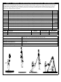
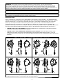
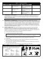
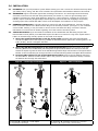
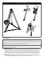
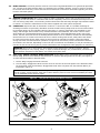
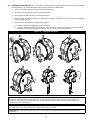
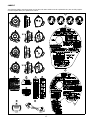
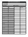
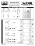
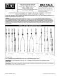
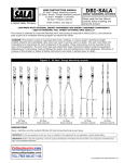
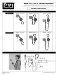
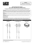
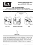
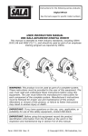
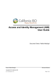
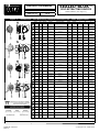
INSTRUCTION MANUAL
SELF-RETRACTING DEVICES
ANSI Z359.14 Class B
ANSI A10.32
SEALED-BLOK™
Model Numbers: (See Figure 1.)
OSHA
The Ultimate in Fall Protection
Figure 1 – Sealed-Blok™ Self-Retracting Lanyards with Fast-Line™ Cable Replacement
A
Model
D
A
W
B
L
B
C
Working
Range
D
A
B
B
D
B
W
C
L
D
A
Working
Range
B
B
C
C
D
D
W
A
L
Working
Range
B
B
C
D
A
D
D
W
B
B
L
C
Working
Range
D
A
B
B
C
D
A
B
A
B
Housing
Fast-Line Lifeline
Range1
Capacity
L
W
D
3400900
RSQ
Retrieval
Aluminum
3900105
50 ft
(15.2 m)
420 lbs
(189 kg)
13.3 in
(34 cm)
10.4 in
(27 cm)
6.9 in
(18 cm)
3400920
Aluminum
3900105
50 ft
(15.2 m)
420 lbs
(189 kg)
13.3 in
(34 cm)
10.4 in
(27 cm)
6.9 in
(18 cm)
Aluminum
3900105
50 ft
(15.2 m)
420 lbs
(189 kg)
13.3 in
(34 cm)
10.4 in
(27 cm)
6.9 in
(18 cm)
3400930
Aluminum
3900105
50 ft
(15.2 m)
310 lbs
(141 kg)
13.3 in
(34 cm)
10.4 in
(27 cm)
6.9 in
(18 cm)
3400940
Aluminum
3900105
50 ft
(15.2 m)
310 lbs
(141 kg)
13.3 in
(34 cm)
10.4 in
(27 cm)
6.9 in
(18 cm)
3400902
Aluminum
3900107
50 ft
(15.2 m)
420 lbs
(189 kg)
13.3 in
(34 cm)
10.4 in
(27 cm)
6.9 in
(18 cm)
3400922
Aluminum
3900107
50 ft
(15.2 m)
420 lbs
(189 kg)
13.3 in
(34 cm)
10.4 in
(27 cm)
6.9 in
(18 cm)
Aluminum
3900107
50 ft
(15.2 m)
420 lbs
(189 kg)
13.3 in
(34 cm)
10.4 in
(27 cm)
6.9 in
(18 cm)
3400932
Aluminum
3900107
50 ft
(15.2 m)
310 lbs
(141 kg)
13.3 in
(34 cm)
10.4 in
(27 cm)
6.9 in
(18 cm)
3400942
Aluminum
3900107
50 ft
(15.2 m)
310 lbs
(141 kg)
13.3 in
(34 cm)
10.4 in
(27 cm)
6.9 in
(18 cm)
3400860
Aluminum
3900108
85 ft
(25.9 m)
420 lbs
(189 kg)
16 in
(41 cm)
9.9 in
(25 cm)
6.7 in
(17 cm)
3400870
Aluminum
3900108
85 ft
(25.9 m)
420 lbs
(189 kg)
16 in
(41 cm)
9.9 in
(25 cm)
6.7 in
(17 cm)
Aluminum
3900108
85 ft
(25.9 m)
420 lbs
(189 kg)
16 in
(41 cm)
9.9 in
(25 cm)
6.7 in
(17 cm)
3400885
Aluminum
3900108
85 ft
(25.9 m)
310 lbs
(141 kg)
16 in
(41 cm)
9.9 in
(25 cm)
6.7 in
(17 cm)
3400910
Aluminum
3900108
85 ft
(25.9 m)
310 lbs
(141 kg)
16 in
(41 cm)
9.9 in
(25 cm)
6.7 in
(17 cm)
3400862
Aluminum
3900111
85 ft
(25.9 m)
420 lbs
(189 kg)
16 in
(41 cm)
9.9 in
(25 cm)
6.7 in
(17 cm)
3400874
Aluminum
3900111
85 ft
(25.9 m)
420 lbs
(189 kg)
16 in
(41 cm)
9.9 in
(25 cm)
6.7 in
(17 cm)
Aluminum
3900111
85 ft
(25.9 m)
420 lbs
(189 kg)
16 in
(41 cm)
9.9 in
(25 cm)
6.7 in
(17 cm)
3400886
Aluminum
3900111
85 ft
(25.9 m)
310 lbs
(141 kg)
16 in
(41 cm)
9.9 in
(25 cm)
6.7 in
(17 cm)
3400912
Aluminum
3900111
85 ft
(25.9 m)
310 lbs
(141 kg)
16 in
(41 cm)
9.9 in
(25 cm)
6.7 in
(17 cm)
3400965
Aluminum
3900112
130 ft
(39.6 m)
420 lbs
(189 kg)
16.8 in
(43 cm)
14 in
(36 cm)
8 in
(20 cm)
3400975
Aluminum
3900112
130 ft
(39.6 m)
420 lbs
(189 kg)
16.8 in
(43 cm)
14 in
(36 cm)
8 in
(20 cm)
Aluminum
3900112
130 ft
(39.6 m)
420 lbs
(189 kg)
16.8 in
(43 cm)
14 in
(36 cm)
8 in
(20 cm)
3400990
Aluminum
3900112
130 ft
(39.6 m)
310 lbs
(141 kg)
16.8 in
(43 cm)
14 in
(36 cm)
8 in
(20 cm)
3401002
Aluminum
3900112
130 ft
(39.6 m)
310 lbs
(141 kg)
16.8 in
(43 cm)
14 in
(36 cm)
8 in
(20 cm)
3400967
Aluminum
3900114
130 ft
(39.6 m)
420 lbs
(189 kg)
16.8 in
(43 cm)
14 in
(36 cm)
8 in
(20 cm)
3400979
Aluminum
3900114
130 ft
(39.6 m)
420 lbs
(189 kg)
16.8 in
(43 cm)
14 in
(36 cm)
8 in
(20 cm)
Aluminum
3900114
130 ft
(39.6 m)
420 lbs
(189 kg)
16.8 in
(43 cm)
14 in
(36 cm)
8 in
(20 cm)
3400991
Aluminum
3900114
130 ft
(39.6 m)
310 lbs
(141 kg)
16.8 in
(43 cm)
14 in
(36 cm)
8 in
(20 cm)
3401004
Aluminum
3900114
130 ft
(39.6 m)
310 lbs
(141 kg)
16.8 in
(43 cm)
14 in
(36 cm)
8 in
(20 cm)
3400650
Aluminum
3900168
175 ft
(53.3 m)
420 lbs
(189 kg)
16.8 in
(43 cm)
14 in
(36 cm)
12.3 in
(31 cm)
3400660
Aluminum
3900168
175 ft
(53.3 m)
420 lbs
(189 kg)
16.8 in
(43 cm)
14 in
(36 cm)
12.3 in
(31 cm)
3400652
Aluminum
3900170
175 ft
(53.3 m)
420 lbs
(189 kg)
16.8 in
(43 cm)
14 in
(36 cm)
12.3 in
(31 cm)
3400661
Aluminum
3900170
175 ft
(53.3 m)
420 lbs
(189 kg)
16.8 in
(43 cm)
14 in
(36 cm)
12.3 in
(31 cm)
3400923
+ Bracket
3400926
+ Bracket
3400871
+ Bracket
3400882
+ Bracket
3400976
+ Bracket
3400987
+ Bracket
1 - In addition to the Working Range, there is a 2 ft (61 cm) Emergency Reserve.
+ Bracket - Includes Mounting Bracket
continued...
FORM NO: 5903774
REV: B
© Copyright 2015, Capital Safety
Figure 1 – Sealed-Blok™ Self-Retracting Lanyards with Fast-Line™ Cable Replacement
Owners of FAST-Line Sealed Blok SRLs with a date of manufacture after January 4, 2015 are no longer required to send their FastLine SRLs back to Capital Safety for recertification in the event of a fall or if the impact indicator indicates the hook is in need of
replacement. Simply replace the cable and hook via FAST-Line in accordance with the FAST-Line Service Manual (5903076) and
complete the Competent Person inspection.
Fast-Line
Lifeline Description
3900105
50 ft. (15 m) of 3/16 in. (4.76 mm) galvanized wire rope, self locking plated steel swiveling snap hook with indicator.
3900106
50 ft. (15 m) of 3/16 in. (4.76 mm) stainless wire rope, self locking plated steel swiveling snap hook with indicator.
2000180
3900107
50 ft. (15 m) of 3/16 in. (4.76 mm) stainless wire rope, self locking stainless steel swiveling snap hook with indicator.
2000181
3900108
85 ft. (26 m) of 3/16 in. (4.76 mm) galvanized wire rope, self locking plated steel swiveling snap hook with indicator.
2000180
3900109
85 ft. (26 m) of 3/16 in. (4.76 mm) stainless wire rope, self locking plated steel swiveling snap hook with indicator.
2000180
3900111
85 ft. (26 m) of 3/16 in. (4.76 mm) stainless wire rope, self locking stainless steel swiveling snap hook with indicator.
2000181
3900112
130 ft. (40 m) of 3/16 in. (4.76 mm) galvanized wire rope, self locking plated steel swiveling snap hook with indicator.
2000180
3900113
130 ft. (40 m) of 3/16 in. (4.76 mm) stainless wire rope, self locking plated steel swiveling snap hook with indicator.
2000180
3900114
130 ft. (40 m) of 3/16 in. (4.76 mm) stainless wire rope, self locking stainless steel swiveling snap hook with indicator.
2000181
3900168
175 ft. (53 m) of 3/16 in. (4.76 mm) galvanized wire rope, self locking plated steel swiveling snap hook with indicator.
2000180
3900169
175 ft. (53 m) of 3/16 in. (4.76 mm) stainless wire rope, self locking plated steel swiveling snap hook with indicator.
2000180
3900170
175 ft. (53 m) of 3/16 in. (4.76 mm) stainless wire rope, self locking stainless steel swiveling snap hook with indicator.
2000181
Hook
Hook
Description
2000180
Material
Gate Strength
Throat Size
2000180
Swiveling Self-Locking Snap Hook with Impact Indicator
Alloy Steel
3,600 lbs (16 kN)
3/4 in (1.9 cm)
2000181
Swiveling Self-Locking Snap Hook with Impact Indicator
Stainless Steel
3,600 lbs (16 kN)
3/4 in (1.9 cm)
Wire Rope Lifeline Tensile Strength:
Galvanized Steel - Min. Tensile Strength 4,200 lbs (18.7 kN)
Stainless Steel - Min. Tensile Strength 3,600 lbs (16.0 kN)
Maximum Arrest Force:
1,350 lbs (6 kN)
Average Arrest Force:
900 lbs (4 Kn)
Maximum Arrest Distance:
42 in (1.1 m)
Average Locking Speed:
4.5 ft/s (1.4 m/s)
RSQ Descent Speed Range:
2-3 ft/s (0.6 - 0.9 m/s)
Fall Arrest
Self-Rescue
Assisted Rescue
Confined Space Entry/Rescue
WARNING: This product is part of a personal fall arrest or rescue system. The user must follow the
manufacturer’s instructions for each component of the system. These instructions must be provided to the
user of this equipment. The user must read and understand these instructions before using this equipment.
Manufacturer’s instructions must be followed for proper use and maintenance of this equipment. Alterations or
misuse of this product or failure to follow instructions may result in serious injury or death.
IMPORTANT: If you have questions on the use, care, or suitability of this equipment for your application,
contact Capital Safety.
IMPORTANT: Before using this equipment, record the product identification information from the ID label in
the ‘Inspection and Maintenance Log’ at the back of this manual.
DESCRIPTION:
Figure 2 identifies key components of the Sealed-Blok™ Self-Retracting Lanyards (SRLs). The Sealed-Blok SRLs
covered in this Instruction Manual are replaceable Fast-Line™ Wire Rope Lifelines (A) which retract into a sealed
aluminum Housing (B). They hang from overhead anchorage by a Carabiner attached through the Anchorage
Handle (C) on the top of the SRL. A Self-Locking Snap Hook (D) on the end of the Lifeline attaches to the
designated Fall Arrest connection on a Full Body Harness. A Bumper (E), equipped with an i-Safe RFID Tag,
protects the Wire Rope and Ferrules securing the Snap Hook from abrasion and corrosion. Sealed-Blok SRL models
may also include RSQ Dual-Mode Rescue/Descent and/or 3-Way Emergency Retrieval options (see Figure 1):
•
SEALED-BLOK™ RSQ™ SRL MODELS: Sealed-Blok RSQ SRLs are equipped with an RSQ Rescue/Descent
Knob (F) for automatic or assisted Rescue Descent.
•
SEALED-BLOK™ 3-WAY EMERGENCY RETRIEVAL SRL-R MODELS: Sealed-Blok Retrieval SRLs meet
ANSI Z359.14 Class B requirements for Self-Retracting Lanyards with Integral Rescue (SRL-R). They are
equipped with a Rescue Hand Crank (G) and Tripod Mounting Bracket (H) for Confined Space Entry and Rescue
Retrieval.
Figure 2 – Sealed-Blok™ Self-Retracting Lanyard (SRL) Components
}
E
C
B
G
E
H
}
C
B
A
D
A
D
Sealed-Blok SRL-R with Retrieval
Sealed-Blok SRL
C
B
F
E
C
B
}
F
E
A
D
G
}
A
D
Sealed-Blok SRL with RSQ Descent
Sealed-Blok SRL-R with RSQ Descent & Retrieval
A - Fast-Line Lifeline B - Housing C - Anchorage Handle D - Self-Locking Snap Hook E - Bumper
F - RSQ Rescue/Descent Knob G - Rescue Hand Crank H - Mounting Bracket
3
1.0 APPLICATIONS
1.1
PURPOSE: Capital Safety Self-Retracting Lanyards (SRLs) are designed to be a component in a personal
fall arrest system (PFAS). Figure 1 illustrates SRLs covered by this instruction manual and their typical
applications. They may be used in most situations where a combination of worker mobility and fall protection
is required (i.e. inspection work, general construction, maintenance work, oil production, confined space
work, etc.). Some SRL models are equipped with integral rescue capability in the form of an RSQ™ Fall
Arrest/Descent Selection Knob or 3-Way Retrieval Hand Crank,
1.2
STANDARDS: Your SRL conforms to the national or regional standard(s) identified on the front cover of
these instructions.
1.3
TRAINING: This equipment is intended to be used by persons trained in its correct application and use. It is the
responsibility of the user to assure they are familiar with these instructions and are trained in the correct care and use
of this equipment. Users must also be aware of the operating characteristics, application limits, and the consequences of
improper use.
1.4
LIMITATIONS: Always consider the following limitations and requirements when installing or using this
equipment:
•
Capacity: This SRL has been compliance tested for use by one person with a combined weight (clothing,
tools, etc.) from 130 lbs (59 kg) to 310 lbs (141 kg).1 Make sure all of the components in your system
are rated to a capacity appropriate to your application.
•
Anchorage: Anchorages selected for fall arrest systems shall have a strength capable of sustaining
static loads applied in the directions permitted by the system of at least:
1.
2.
5,000 lbs. (22.2 kN) for non-certified anchorages, or
Two times the maximum arresting force for certified anchorages.
When more than one fall arrest system is attached to an anchorage, the strengths set forth in (1) and
(2) above shall be multiplied by the number of systems attached to the anchorage.
FROM OSHA 1926.500 AND 1910.66: Anchorages used for attachment of personal fall arrest systems shall be
independent of any anchorage being used to support or suspend platforms, and capable of supporting at least 5,000 lbs.
per user attached, or be designed, installed, and used as part of a complete personal fall arrest systems which maintains
a safety factor of at least two, and is under the supervision of a qualified person.
1
•
Locking Speed: Situations which do not allow for an unobstructed fall path should be avoided. Working
in confined or cramped spaces may not allow the body to reach sufficient speed to cause the SRL to lock
if a fall occurs. Working on slowly shifting material, such as sand or grain,may not allow enough speed
buildup to cause the SRL to lock. A clear path is required to assure positive locking of the SRL.
•
Free fall: When used correctly, SRLs will limit the free fall distance to 2 ft. (61 cm). To avoid increased fall
distances, do not work above the anchorage level. Do not lengthen SRLs by connecting a lanyard or
similar component without consulting Capital Safety. Never clamp, knot, or prevent the lifeline
from retracting or being taut. Avoid slack line.
•
Swing Falls: Swing Falls occur when the anchorage point is not directly above the point where a fall
occurs. The force of striking an object in a swing fall may cause serious injury (see Figure 3A). Minimize
swing falls by working as directly below the anchorage point as possible.
•
Fall Clearance: Figure 3B illustrates Fall Clearance. SRL Fall Arrest Systems should have a minimum Fall
Clearance of 6 ft (2 m) for falls from a standing position where the SRL is anchored directly overhead. Falls
from a kneeling or crouching position will require an additional 3 ft (1 m) of Fall Clearance. In a swing fall
situation, the total vertical fall distance will be greater than if the user had fallen directly below the
anchorage point and may require additional Fall Clearance. The table in Figure 3 provides the minimum
vertical Fall Clearance needed below the working level of the SRL user where added Swing Fall distance
is within the recommended range of use.
•
Hazards: Use of this equipment in areas where surrounding hazards exist may require additional precautions to
reduce the possibility of injury to the user or damage to the equipment. Hazards may include, but are not limited
to: high heat, caustic chemicals, corrosive environments, high voltage power lines, explosive or toxic gases, moving
machinery, or overhead materials that may fall and contact the user or fall arrest system. Avoid working where
your lifeline may cross or tangle with that of another worker. Avoid working where an object may fall and strike the
lifeline; resulting in loss of balance or damage to the lifeline. Do not allow the lifeline to pass under arms or between
legs.
•
Sharp Edges: Avoid working where the lifeline will be in contact with or abrade against unprotected
sharp edges. Where contact with a sharp edge is unavoidable, cover the edge with a protective material.
Capacity: 130 lbs -310 lbs (59 kg- 141 kg) is the capacity range required by standard ANSI Z359.14. Some DBI-SALA SRLs are tested to a 420 lbs (191 kg)
capacity. See Figure 1 for the SRL models covered by this instruction and their capacities.
4
Figure 3 – Fall Clearance and Swing Fall
FC = Minimum Fall Clearance
A
B
FC
ft (m)
H
FC
! WARNING
V - Vertical Distance from Anchorage Point
V
0
(0.0)
10
(3)
20
(6.1)
30
(9.1)
40
(12.2)
50
(15.2)
60
(18.3)
70
(21.3)
80
(24.4)
90
(27.4)
100
(30.5)
110
(33.5)
120
(36.6)
130
(39.6)
140
(42.7)
150
(45.7)
160
(48.8)
170
(51.8)
180
(54.9)
190
(57.9)
H - Horizontal Distance from Anchorage Point
0
(0.0)
2
(0.6)
4
(1.2)
6
(1.8)
8
(2.4)
10
(3.0)
12
(3.7)
14
(4.3)
16
(4.9)
18
(5.5)
20
(6.1)
6
(2)
6
(2)
6
(2)
6
(2)
6
(2)
6
(2)
6
(2)
6
(2)
6
(2)
6
(2)
6
(2)
6
(2)
6
(2)
6
(2)
6
(2)
6
(2)
6
(2)
6
(2)
6
(2)
6
(2)
8
(2.6)
6.2
(2.1)
6.1
(2)
6.1
(2.1)
6
(2)
6
(2)
6
(2)
6
(2)
6
(2)
6
(2)
6
(2)
6
(2)
6
(2)
6
(2)
6
(2)
6
(2)
6
(2)
6
(2)
6
(2)
6
(2)
6.8
(2.3)
6.4
(2.1)
6.3
(2.1)
6.2
(2.1)
6.2
(2.1)
6.1
(2)
6.1
(2.1)
6.1
(2)
6.1
(2.1)
6.1
(2)
6.1
(2.1)
6.1
(2)
6.1
(2.1)
6.1
(2)
6.1
(2.1)
6
(2)
6
(2)
6
(2)
6
(2)
7.7
(2.6)
6.9
(2.3)
6.6
(2.2)
6.4
(2.1)
6.4
(2.2)
6.3
(2.1)
6.3
(2.1)
6.2
(2)
6.2
(2.1)
6.2
(2)
6.2
(2.1)
6.1
(2)
6.1
(2.1)
6.1
(2)
6.1
(2.1)
6.1
(2)
6.1
(2)
6.1
(2)
6.1
(2)
8.8
(2.9)
7.5
(2.5)
7
(2.3)
6.8
(2.2)
6.6
(2.2)
6.5
(2.1)
6.5
(2.2)
6.4
(2.1)
6.4
(2.2)
6.3
(2.1)
6.3
(2.1)
6.3
(2.1)
6.2
(2.1)
6.2
(2)
6.2
(2.1)
6.2
(2)
6.2
(2.1)
6.2
(2)
6.2
(2.1)
8.4
(2.7)
7.6
(2.5)
7.2
(2.4)
7
(2.3)
6.8
(2.2)
6.7
(2.2)
6.6
(2.2)
6.6
(2.2)
6.5
(2.1)
6.5
(2.2)
6.4
(2.1)
6.4
(2.1)
6.4
(2.1)
6.3
(2.1)
6.3
(2.1)
6.3
(2.1)
6.3
(2.1)
6.3
(2.1)
9.3
(3)
8.3
(2.7)
7.8
(2.5)
7.4
(2.5)
7.2
(2.4)
7
(2.3)
6.9
(2.3)
6.8
(2.3)
6.7
(2.2)
6.7
(2.2)
6.6
(2.2)
6.6
(2.2)
6.5
(2.1)
6.5
(2.2)
6.4
(2.1)
6.4
(2.1)
6.4
(2.1)
6.4
(2.1)
9.1
(3)
8.4
(2.7)
7.9
(2.6)
7.6
(2.5)
7.4
(2.5)
7.2
(2.3)
7.1
(2.4)
7
(2.3)
6.9
(2.3)
6.8
(2.2)
6.8
(2.3)
6.7
(2.2)
6.7
(2.2)
6.6
(2.2)
6.6
(2.2)
6.5
(2.1)
6.5
(2.2)
9.1
(2.9)
8.5
(2.8)
8.1
(2.6)
7.8
(2.6)
7.6
(2.5)
7.4
(2.5)
7.3
(2.4)
7.2
(2.4)
7.1
(2.3)
7
(2.3)
6.9
(2.2)
6.9
(2.3)
6.8
(2.2)
6.8
(2.3)
6.7
(2.2)
6.7
(2.2)
9.9
(3.2)
9.1
(3)
8.6
(2.8)
8.3
(2.7)
8
(2.6)
7.8
(2.6)
7.6
(2.5)
7.5
(2.5)
7.3
(2.4)
7.2
(2.4)
7.2
(2.3)
7.1
(2.4)
7
(2.3)
7
(2.3)
6.9
(2.2)
6.9
(2.3)
9.9
(3.2)
9.2
(3)
8.8
(2.9)
8.5
(2.7)
8.2
(2.7)
8
(2.6)
7.8
(2.6)
7.7
(2.5)
7.5
(2.5)
7.4
(2.4)
7.3
(2.4)
7.2
(2.3)
7.2
(2.4)
7.1
(2.3)
7
(2.3)
Added Swing Fall Length is not within the recommended work zone.
NOTE: Fall Clearance (FC) values in the above table assume a fall from a standing position. If the
worker is kneeling or crouching near an edge when a fall occurs, an additional 3 ft (1 m) of Fall
Clearance is needed.
2.0 USE
2.1
RESCUE PLAN: When using this equipment, the employer must have a rescue plan and the means at hand
to implement it and communicate that plan to users, authorized persons, and rescuers.
2.2
INSPECTION FREQUENCY: SRLs shall be inspected by the authorized person1 or rescuer2 before each
use (See Table 2). Additionally, inspections shall be conducted by a competent person3 other than the
user. Extreme working conditions (harsh environment, prolonged use, etc.) may necessitate more frequent
competent person inspections. The competent person shall use the Inspection Schedule (Table 1) to
determine appropriate inspection intervals. Inspection procedures are described in the “Inspection Checklist”
(Table 2). Results of the Competent Person inspection should be recorded in the “Inspection and Maintenance
Log” on the back pages of these instructions or recorded with the i-Safe™ system (see Section 5).
2.3
NORMAL OPERATIONS: Normal operation will allow the lifeline to extend and retract with no hesitation
or slack as the worker moves at normal speeds. If a fall occurs, a speed sensing brake system will activate,
stopping the fall and absorbing much of the energy created. Sudden or quick movements should be avoided
during normal work operation, as this may cause the SRL to lock up. For falls which occur near the end of
the lifeline travel, a reserve lifeline system or Energy Absorber has been incorporated to reduce the fall
arrest forces. If the SRL has been subjected to fall arrest forces: remove it from service, mark or tag as
“UNUSABLE”, inspect and service as instructed in Sections 5 and 6.
2.4
BODY SUPPORT: A Full Body Harness must be used with the Self-Retracting Lanyard. The harness
connection point must be above the user’s center of gravity. A body belt is not authorized for use with the
Self-Retracting Lanyard. If a fall occurs when using a body belt it may cause unintentional release or physical
trauma from improper body support.
1
2
3
Authorized Person: A person assigned by the employer to perform duties at a location where the person will be exposed to a fall hazard.
Rescuer: Person or persons other than the rescue subject acting to perform an assisted rescue by operation of a rescue system.
Competent Person: An individual designated by the employer to be responsible for the immediate supervision, implementation, and monitoring of the
employer’s managed fall protection program who, through training and knowledge, is capable of identifying, evaluating, and addressing existing and potential fall
hazards, and who has the employer’s authority to take prompt corrective action with regard to such hazards.
5
Table 1 – Inspection Schedule
Type of Use
Infrequent to Light
Application Examples
Rescue and Confined Space,
Factory Maintenance
Moderate to Heavy
Transportation, Residential
Construction, Utilities,
Warehouse
Sever to Continuous
Commercial Construction, Oil
and Gas, Mining
2.5
Conditions of Use
Good Storage Conditions,
Indoor or Infrequent Outdoor
Use, Room Temperature, Clean
Environments
Fair Storage Conditions, Indoor
and Extended Outdoor Use, All
Temperatures, Clean or Dusty
Environments
Harsh Storage Conditions,
Prolonged or Continuous
Outdoor Use, All Temperatures,
Dirty Environment
Inspection Frequency
Competent Person
Annually
Semi-Annually to Annually
Quarterly to Semi-Annually
COMPATIBILITY OF COMPONENTS: Unless otherwise noted, Capital Safety equipment is designed for use
with Capital Safety approved components and subsystems only. Substitutions or replacements made with non
approved components or subsystems may jeopardize compatibility of equipment and may affect safety and
reliability of the complete system.
IMPORTANT: Follow manufacturer’s instructions for components and subsystems in your personal fall arrest system.
2.6
COMPATIBILITY OF CONNECTORS: Connectors are considered to be compatible with connecting
elements when they have been designed to work together in such a way that their sizes and shapes do not
cause their gate mechanisms to inadvertently open regardless of how they become oriented. Contact Capital
Safety if you have any questions about compatibility. Connectors (hooks, carabiners, and D-rings) must be
capable of supporting at least 5,000 lbs. (22.2 kN). Connectors must be compatible with the anchorage or
other system components. Do not use equipment that is not compatible. Non-compatible connectors may
unintentionally disengage (see Figure 4). Connectors must be compatible in size, shape, and strength. Selflocking snap hooks and carabiners are required.
2.7
MAKING CONNECTIONS: Snap hooks and carabiners used with this equipment must be self-locking.
Ensure all connections are compatible in size, shape and strength. Do not use equipment that is not
compatible. Ensure all connectors are fully closed and locked. Capital Safety connectors (snap hooks and
carabiners) are designed to be used only as specified in each product’s user’s instructions. See Figure 5 for
examples of inappropriate connections. Do not connect snap hooks and carabiners:
A. To a D-ring to which another connector is attached.
B. In a manner that would result in a load on the gate.
NOTE: Large throat snap hooks should not be connected to standard size D-rings or similar objects which will
result in a load on the gate if the hook or D-ring twists or rotates, unless the snap hook is equipped with a 3,600 lb
(16 kN) gate. Check the marking on your snap hook to verify that it is appropriate for your application.
C. In a false engagement, where features that protrude from the snap hook or carabiner catch on the
anchor, and without visual confirmation seems to be fully engaged to the anchor point.
D. To each other.
E.
Directly to webbing or rope lanyard or tie-back (unless the manufacturer’s instructions for both the
lanyard and connector specifically allows such a connection).
F.
To any object which is shaped or dimensioned such that the snap hook or carabiner will not close and
lock, or that roll-out could occur.
G. In a manner that does not allow the connector to align properly while under load.
Figure 4 – Unintentional Disengagement
If the connecting element to which a snap hook (shown) or carabiner attaches
is undersized or irregular in shape, a situation could occur where the connecting
element applies a force to the gate of the snap hook or carabiner. This force may
cause the gate (of either a self-locking or a non-locking snap hook) to open,
allowing the snap hook or carabiner to disengage from the connecting point.
Figure 5 – Inappropriate Connections
A.
B.
C.
D.
Small ring or other
non-compatibly
shaped element
E.
Force is applied to the
Snap Hook.
The Gate presses against
the Connecting Ring.
The Gate opens allowing
the Snap Hook to slip off.
6
F.
G.
3.0 INSTALLATION
3.1
PLANNING: Plan your fall protection system before starting your work. Account for all factors that may affect
your safety before, during, and after a fall. Consider all requirements and limitations defined in this manual.
3.2
ANCHORAGE: Figure 6 illustrates typical SRL anchorage connections. The anchorage should be directly
overhead to minimize Free Fall and Swing Fall hazards (see Section 2). Select a rigid anchorage point
capable of sustaining the static loads defined in Section 2.2. Some industries, including the oil and gas
industry require secondary Dropped Object Anchorage to prevent the SRL from dropping if the primary
anchorage point fails. Sealed-Blok SRLs include a Tie-Off Adaptor and Carabiner for this purpose.
3.3
HARNESS CONNECTION: A Full Body Harness is required for Fall Arrest applications. Connect the Snap
Hook on the SRL Lifeline to the Back Dorsal D-Ring on the Full Body Harness. (see Figure 7). For situations
such as ladder climbing, it may be useful to connect to the front Sternal D-Ring. Consult the harness
manufacturer’s instructions for details regarding use of the harness connection points.
3.4
TRIPOD MOUNTING: Figure 8 illustrates installation of the Sealed-Blok Self-Retracting Lanyard with
Retrieval Hand-Crank (SRL-R) on a DBI-SALA Tripod. The SRL-R is mounted on a leg of the Tripod and the
Lifeline is routed through a Pulley System on the Head of the Tripod:
1. Secure the Quick Mount Bracket on the leg of the Tripod: Assemble the Quick Mount Bracket
around the Upper Tube of the Tripod Leg. Position as desired and then tighten the mounting bolts to 15
ft-lbs (20 Nm). Do not overtighten the bolts.
IMPORTANT: Never mount the Quick Mount Bracket on the Lower (Telescoping) Tube of the Tripod Leg.
2. Secure the SRL Mounting Bracket on the Quick Mount Bracket: Position the notches in the SRL
Mounting Bracket over the Rod Ends protruding from the Quick Mount Bracket and then pivot the SRL
toward the Tripod Leg until the holes in the SRL Mounting Bracket align with the holes in the Quick Mount
Bracket. Insert the Mounting Pin through the holes in the SRL Mounting Bracket and Quick Mount Bracket.
3. Route the SRL Lifeline over the Tripod Head Mount Pulleys: Remove the two Retainer Pins from
the Head Mount. Position the SRL Lifeline cable in the grooves in the two Head Mount Pulleys. Reinsert
the Retainer Pins through the Head Mount.
Figure 6 – Anchorage Connections
B
A
B
Figure 7 – SRL Connections
A
A
B
C
D
A
A
C
C
B
E
C
B
D
B
C
A - Anchorage B - Carabiner C - Tie-Off Adapter
D - Dropped Object Anchorage
A - Anchorage B - Anchorage Connector C - Connector
(Carabiner) D - Snap Hook E - Dorsal D-Ring
7
Figure 8 – Tripod Mounting
1
2
3
4.0 OPERATION
WARNING: Do not alter or intentionally misuse this equipment. Consult Capital Safety when using this
equipment in combination with components or subsystems other than those described in this manual. Some
subsystem and component combinations may interfere with the operation of this equipment. Use caution when
using this equipment around moving machinery, electrical hazards, chemical hazards, sharp edges, or overhead
materials that may fall onto the lifeline. Do not loop the lifeline around small structural members. Failure to heed
this warning may result in equipment malfunction, serious injury, or death.
WARNING: Consult your doctor if there is reason to doubt your fitness to safely absorb the shock from a fall
arrest. Age and fitness seriously affect a worker’s ability to withstand falls. Pregnant women or minors must not
use DBI-SALA Self-Retracting Lanyards.
4.1
BEFORE EACH USE: Before each use of this fall protection equipment carefully inspect it to assure it is in
good working condition. Check for worn or damaged parts. Ensure all bolts are present and secure. Check
that the lifeline is retracting properly by pulling out the line and allowing it to slowly retract. If there is any
hesitation in retraction the unit should be marked as “UNUSABLE” and inspected and serviced per Sections
5 and 6. Inspect the lifeline for cuts, frays, burns, crushing and corrosion. Check locking action by pulling
sharply on the line. See Section 5 for inspection details. Do not use if inspection reveals an unsafe condition.
4.2
AFTER A FALL: Any equipment which has been subjected to the forces of arresting a fall or exhibits
damage consistent with the effect of fall arrest forces; must be removed from service immediately, marked
as “UNUSABLE”, and inspected and serviced per the instructions in Sections 5 and 6.
8
4.3
BODY SUPPORT: A full body harness must be worn when using DBI-SALA SRLs. For general fall protection
use, connect to the back Dorsal D-Ring. For situations such as ladder climbing, it may be useful to connect
to the front Sternal D-Ring. Consult the harness manufacturer’s instructions for details regarding use of the
harness connection points.
IMPORTANT: Do not use a body belt for free fall applications. See OSHA 1926.502 for guidelines.
4.4
MAKING CONNECTIONS: When using a hook to make a connection, ensure roll-out cannot occur (see
Figure 5). Do not use hooks or connectors that will not completely close over the attachment object. Do not
use non-locking snap hooks. The mounting surface should meet the anchorage strength requirements stated
in section 2.2. Follow the manufacturer’s instructions supplied with each system component.
4.5
OPERATION: Inspect the SRL as described in section 5.0. Connect the SRL to a suitable anchorage or
anchorage connector as previously described. Connect the Self-Locking Snap Hook on the end of the lifeline
to the Dorsal D-Ring on the Full Body Harness (see Figure 7). Ensure connections are compatible in size,
shape, and strength. Ensure hook is fully closed and locked. Once attached, the worker is free to move
about within the recommended working area at normal speeds. If the RSQ Selection Knob is set to ‘Fall
Arrest’, the SRL will arrest the fall. If the RSQ Selection Knob is set to ‘Descent’, the SRL will automatically
descend the user to a lower level when a fall occurs. When working with an SRL, always allow the lifeline
to recoil back into the device under control. A tag line may be required to extend or retract the lifeline
during connection and disconnection operations. A tag line can be used to prevent uncontrolled retraction
of the lifeline into the SRL. Depending on the work site environment and conditions, it may be necessary to
restrain the free end of the tag line to prevent interference and entanglement with equipment or machinery.
WARNING: Do not tie or knot lifeline. Avoid lifeline contact with sharp or abrasive surfaces. Inspect
lifeline frequently for cuts, fraying, burns, or signs of chemical damage. Dirt, contaminants, and water can
lower dielectric properties of the lifeline. Use caution near power lines.
4.6
RSQ™ FALL ARREST/DESCENT MODE SELECTION: Sealed-Blok™ RSQ™ Dual-Mode SRLs are equipped
with an RSQ Knob to select between the Fall Arrest or Descent operating modes of the SRL (see Figure 9).
To select Fall Arrest Mode or Descent Mode:
1.
Pull the RSQ™ Engagement Knob outward.
2.
Turn the RSQ™ Engagement Knob until the arrow on the face of the knob points to the Selection Notch
for the desired mode and the RSQ™ Engagement Knob clicks into place with the Selection Notch (as
illustrated in Figure 9).
IMPORTANT: Sealed-Blok RSQ SRLs are designed for emergency fall arrest and descent and may only be
used for a single, vertical descent. If the SRL is used to descend, remove it from service immediately and send
it to an authorized service center for repair.
Figure 9 – RSQ Fall Arrest/Descent Mode Selection
B
A
Descent Mode
Fall Arrest Mode
A - Descent Selection Notch B - Fall Arrest Selection Notch
9
RSQ Descent Mode: In Descent Mode, the user automatically descends to a lower level when a fall occurs.
RSQ Fall Arrest Mode: In Fall Arrest Mode, the SRL arrests the fall and the user remains suspended.
Descent is activated and controlled with the RSQ™ Engagement Knob Pull Ring or an optional Extension Pole
Release Tool (see Figure 10):
•
Engagement Knob Pull Ring: Figure 10 illustrates operation of the Engagement Knob Pull Ring. To
disengage Fall Arrest Mode and initiate descent, grasp the Pull Ring and pull the Engagement Knob
straight out. To stop descent; release the Pull Ring to re-engage Fall Arrest Mode. To fully engage
Descent Mode so descent continues without pulling the Pull Ring, turn the Engagement Knob counterclockwise until the arrow on face of the knob points to the Descent Selection Notch (see Figure 9).
NOTE: 80 lbs - 100 lbs (0.36 kN - 0.45 kN) of pulling force is required to release the RSQ™
Engagement Knob from Fall Arrest Mode.
•
Extension Pole Release Tool: Insert the Extension Pole Release Tool from any direction so the ends of
the Release Forks surround the base of the RSQ™ Engagement Knob below the Knurled Ridge and Pull
Ring (see Figure 10). To disengage Fall Arrest Mode and initiate descent, push forward on the Extension
Pole until the RSQ™ Engagement Knob is fully lodged in the Release Fork. Descent will continue as long
as the Release Fork is fully lodged between the RSQ™ Engagement Knob and the Housing. Removal of
Release Fork may cause unit to re-engage Fall Arrest Mode.
IMPORTANT: The Release Fork on the Extension Pole Release tool is tapered to push the RSQ™ Engagement
Knob straight out as the fork is pushed forward on the knob. It is not necessary to pry the knob with the
Extension Pole. Prying could break off the knob.
Figure 10 – Assisted Rescue Operation
Engagement Knob Pull Ring
Extension Pole Release Tool
Insert Fork
under Pull Ring
and Knurled
Ridge on
Engagement
Knob.
Pull to descend.
270°
90°
Release to stop descent.
Fork can be inserted from 90° to 270 °.
Pull & turn
counterclockwise
for hands-free
Descent Mode.
10
4.7
RETRIEVAL OPERATION: Figure 11 illustrates operation of the Integral Rescue Hand Crank on Sealed-Blok
Retrieval SRL-Rs. To activate Retrieval mode and use the Rescue Hand Crank:
1.
Loosen the Locking Thumb Screw to release the Crank Arm.
2.
Rotate the Retrieval Handle up from the SRL Body 90°.
3.
Pull and hold the Shift Knob in the unlocked position.
4.
Push the Crank Arm in and release the Shift Knob to engage. If needed, rotate the Crank Arm clockwise
to help engage the gear.
5.
Raise and lower the Lifeline as illustrated in Figure 11
A. To Raise: Rotate the Crank Arm counterclockwise.
B. To Lower: Rotate the Crank Arm clockwise. After Fall Arrest; crank the Crank Arm counterclockwise
slightly first to release the Fall Arrest Brake, then crank the Crank Arm clockwise.
Figure 11 – Retrieval Operation
1
2
3
4
5A
5B
RETRIEVAL OVERLOAD: Sealed-Blok SRL-Rs do not incorporate an Overload Clutch to limit the force exerted
on the drive components and attached person. Avoid line slack while in Retrieval mode. Also, monitor the
individual during retrieval to ensure they are not subjected to excessive force from continued lifting after
entanglement on an obstruction.
NOTE: A minimum load of 75 lbs (33.9 kg) is required to lower or pay out the Lifeline. A force of 30 lbs (0.13
kN) is required to operate the Retrieval system when loaded to capacity.
CAUTION: Stop cranking when the Lifeline is fully extended or retracted. Continued cranking can damage
components.
11
4.8
RETRIEVAL DISENGAGEMENT: To disengage Retrieval mode:
CAUTION: When Retrieval mode is disengaged, any extended Lifeline will retract into the SRL. To avoid
possible injury, retract the Lifeline prior to disengagement or hold onto the Lifeline.
1.
Remove any load from the Lifeline.
2.
Pull and hold the Shift Knob in the unlocked position.
3.
Pull the Crank Arm out to disengage and then release the Shift Knob.
4.
Pull out and rotate the Retrieval Handle down toward the SRL Body to stowed position.
5.0 INSPECTION
5.1
i-Safe™ RFID TAG: The Self-Retracting Lanyard includes
an i-Safe™ Radio Frequency Identification (RFID) tag. The
RFID tag can be used in conjunction with the i-Safe handheld
reading device and web based portal to simplify inspection and
inventory control and provide records for your fall protection
equipment. For details, contact a Capital Safety Customer
Service representative (see back cover); or if you have already
registered, go to http://isafe3.capitalsafety.com/Pro/. Follow
the instructions provided with your i-Safe handheld reader, or
on the web portal, to transfer your data to your web log.
5.2
INSPECTION FREQUENCY: The Sealed-Blok Self-Retracting Lanyard must be inspected at the intervals
defined in Section 2.2 - Inspection Frequency”. Inspection procedures are described in the “Inspection
Checklist” (Table 2).
Figure 12 – i-Safe RFID Tag
IMPORTANT: If the Self-Retracting Lanyard has been subjected to fall arrest or impact forces it must be
immediately removed from service, marked as “UNUSABLE”, and inspected by a Competent Person per
instructions in Table 2 to determine service options.
IMPORTANT: Extreme working conditions (harsh environments, prolonged use, etc.) may require
increasing the frequency of inspections.
5.3
UNSAFE OR DEFECTIVE CONDITIONS: If inspection reveals an unsafe defective condition, remove the
Self-Retracting Lanyard from service immediately, mark as “UNUSABLE”, and perform a Competent Person
inspection to determine service options.
NOTE: Only Capital Safety or parties authorized in writing may make repairs other than FAST-Line Lifeline
replacement to this equipment.
5.4
PRODUCT LIFE: The functional life of DBI-SALA Self-Retracting Lanyards is determined by work conditions
and maintenance. As long as the product passes inspection criteria, it may remain in service.
6.0 CLEANING, SERVICE, STORAGE, AND TRANSPORT
6.1
CLEANING: Cleaning procedures for the Self-Retracting Lanyard are as follows:
•
Periodically clean the exterior of the SRL using water and a mild soap solution. Position the SRL so
excess water can drain out. Clean labels as required.
•
Clean lifeline with water and mild soap solution. Rinse and thoroughly air dry. Do not force dry with
heat. An excessive buildup of dirt, paint, etc. may prevent the lifeline from fully retracting back into the
housing causing a potential free fall hazard. Replace lifeline if excessive buildup is present.
6.2
SERVICE: FAST-Line Lifelines can be replaced in the field by a Competent Person1. See Figure 1 for the
required FAST-Line Lifeline Replacement Kit. Install the lifeline per the instructions in the Service Manual
(5903076) include with the FAST-Line kit. Always perform a complete Competent Person inspection after
replacing the FAST-Line Lifeline. Additional service, determined from the Competent Person inspection, must
be completed by an authorized service center. Do not attempt to disassemble the SRL or lubricate any parts.
6.3
STORAGE AND TRANSPORT: Store and transport Self-Retracting Lanyard in a cool, dry, clean environment
out of direct sunlight. Avoid areas where chemical vapors may exist. Thoroughly inspect the SRL after any
period of extended storage.
1
Competent Person: An individual designated by the employer to be responsible for the immediate supervision, implementation, and monitoring of the
employer’s managed fall protection program who, through training and knowledge, is capable of identifying, evaluating, and addressing existing and potential fall
hazards, and who has the employer’s authority to take prompt corrective action with regard to such hazards.
12
LABELS
The following labels must be present on the Ultra-Lok SRL. Labels must be replaced if they are not fully legible.
Contact Capital Safety for replacement labels.
A
B
A
D
B
E
A
G
C
D
E
A
J
I
B
D
F
A
H
J
C
D
I
C
F
D
E
G
H
Mfrd/Fab.
Lot
Service Dates /
Dates de Réparation
F
I
J
13
Table 2 – Inspection Checklist
Component:
Authorized
Person or
Rescuer
Inspection:
SRL
(Diagram 1)
Competent
Person
Inspect for loose bolts and bent or damaged parts.
Inspect Housing (A) for distortion, cracks, or other damage.
Inspect the Swivel Eye (B) for distortion, cracks, or other damage. The Swivel Eye should be attached
securely to the SRL, but should pivot freely.
The Lifeline (C) should pull out and retract fully without hesitation or creating a slack line condition.
Ensure device locks up when lifeline is jerked sharply. Lockup should be positive with no slipping.
NOTE: SRLs with RSQ should be in Fall Arrest Mode for this test (see Figure 8)
The labels must be present and fully legible (see “Labels”).
Look for signs of corrosion on the entire unit.
Swivel Snap Hook & Impact
Indicator
(Diagram 2)
Inspect the Swivel Snap Hook for signs of damage, corrosion, and working condition. Swivel should
rotate freely. Inspect the Impact Indicator. If the Red Band is displayed (Indicated Mode), impact
loading has occurred and the SRL must be removed from service and inspected. Do not attempt to
reset the Impact Indicator. Return the SRL to an authorized service center for resetting. NOTE: The
Swivel will not turn freely when the Impact Indicator is in Indicated Mode.
⌧ FAST-Line Means LIFETIME: If the Red Band on the Swivel Snap Hook Impact Indicator is
displaying (Indicated Mode); contact Capital Safety regarding service by an Authorized Service Center,
or replace the FAST-Line Lifeline per the instructions in the “FAST-Line Lifeline Replacement Kit Service
Manual (5903076)” and complete the Competent Person inspection.
FAST-Line Wire Rope Lifeline
(Diagram 3)
Inspect wire rope for cuts, kinks, broken wires, bird-caging, welding splatter, corrosion, chemical
contact areas, or severely abraded areas. Slide the cable bumper up and inspect ferrules for cracks or
damage and inspect the wire rope for corrosion and broken wires. Replace the wire rope assembly if
there are six or more randomly distributed broken wires in one lay, or three or more broken wires in
one strand in one lay. A “lay” of wire rope is the length of wire rope it takes for a strand (the larger
groups of wires) to complete one revolution or twist along the rope. Replace the wire rope assembly if
there are any broken wires within 1 inch (25 mm) of the ferrules.
⌧ FAST-Line Means LIFETIME: If inspection in the previous step indicates lifeline replacement;
contact Capital Safety regarding service by an Authorized Service Center, or replace the FAST-Line
Lifeline per the instructions in the “FAST-Line Lifeline Replacement Kit Service Manual (5903076)” and
complete the Competent Person inspection.
RSQ Components
(Diagram 4)
A hand pull test should be performed on RSQ™ Components prior to each use:
Retrieval Integral Rescue Hand
Crank
(Diagram 5)
Inspect the Crank Arm (A) for distortion or other damage. Ensure that the Retrieval Handle (B) can be
folded out and secured in the cranking position.
1.
2.
3.
Set RSQ Engagement Knob to Descent position (Diagram 4).
Grasp the lifeline and pull firmly to engage descent mechanism.
Continue to smoothly pull out approximately 3 feet (1 m) of cable. Steady resistance should be
felt when pulling out cable.
Ensure the Retrieval Shift Knob (C) can be pulled out to the unlocked position and then released,
locking the Crank Arm in both the engaged and disengaged positions.
Test the retrieval feature for proper operation by raising and lowering a test weight of at least 75 lbs
(34 kg). When the Retrieval Handle is released, the weight should not move and the Retrieval Handle
should remain in position (no movement). A ‘clicking’ sound should be audible when raising the load.
Diagram 1 – SRL Inspection
B
A
C
Diagram 2 – Impact Indicator
B
Diagram 3 – Wire Rope
Kinked Wire Rope
Red
Band
A
C
Broken Wires
Indicated
Mode
Normal
Mode
Bird-Caging
Welding Splatter
Diagram 4 – RSQ Engagement Knob
Diagram 5 – Retrieval Components
B
D
A
C
14
INSPECTION AND MAINTENANCE LOG
SERIAL NUMBER:
MODEL NUMBER:
DATE PURCHASED:
INSPECTION DATE
Approved By:
Approved By:
Approved By:
Approved By:
Approved By:
Approved By:
Approved By:
Approved By:
Approved By:
Approved By:
Approved By:
Approved By:
Approved By:
Approved By:
Approved By:
Approved By:
Approved By:
Approved By:
DATE OF FIRST USE:
INSPECTION ITEMS
NOTED
CORRECTIVE ACTION
MAINTENANCE
PERFORMED
LIMITED LIFETIME WARRANTY
Warranty to End User: D B Industries, LLC d/b/a Capital Safety USA (“CAPITAL SAFETY”) warrants to the
original end user (“End User”) that its products are free from defects in materials and workmanship under
normal use and service. This warranty extends for the lifetime of the product from the date the product is
purchased by the End User, in new and unused condition, from a CAPITAL SAFETY authorized distributor.
CAPITAL SAFETY’S entire liability to End User and End User’s exclusive remedy under this warranty is limited
to the repair or replacement in kind of any defective product within its lifetime (as CAPITAL SAFETY in its sole
discretion determines and deems appropriate). No oral or written information or advice given by CAPITAL
SAFETY, its distributors, directors, officers, agents or employees shall create any different or additional
warranties or in any way increase the scope of this warranty. CAPITAL SAFETY will not accept liability for defects
that are the result of product abuse, misuse, alteration or modification, or for defects that are due to a failure to
install, maintain, or use the product in accordance with the manufacturer’s instructions.
CAPITAL SAFETY’S WARRANTY APPLIES ONLY TO THE END USER. THIS WARRANTY IS THE ONLY WARRANTY
APPLICABLE TO OUR PRODUCTS AND IS IN LIEU OF ALL OTHER WARRANTIES AND LIABILITIES, EXPRESSED
OR IMPLIED. CAPITAL SAFETY EXPRESSLY EXCLUDES AND DISCLAIMS ANY IMPLIED WARRANTIES OF
MERCHANTABILITY OR FITNESS FOR A PARTICULAR PURPOSE, AND SHALL NOT BE LIABLE FOR INCIDENTAL,
PUNITIVE OR CONSEQUENTIAL DAMAGES OF ANY NATURE, INCLUDING WITHOUT LIMITATION, LOST PROFITS,
REVENUES, OR PRODUCTIVITY, OR FOR BODILY INJURY OR DEATH OR LOSS OR DAMAGE TO PROPERTY, UNDER
ANY THEORY OF LIABILITY, INCLUDING WITHOUT LIMITATION, CONTRACT, WARRANTY, STRICT LIABILITY, TORT
(INCLUDING NEGLIGENCE) OR OTHER LEGAL OR EQUITABLE THEORY.
The Ultimate in Fall Protection
CAPITAL SAFETY
USA & Latin America
3833 SALA Way
Red Wing, MN 55066-5005
Toll Free: 800.328.6146
Phone: 651.388.8282
Fax: 651.388.5065
[email protected]
Canada
260 Export Boulevard
Mississauga, ON L5S 1Y9
Phone: 905.795.9333
Toll-Free: 800.387.7484
Fax: 888.387.7484
[email protected]
Northern Europe
5a Merse Road
North Moons, Moat
Reditch, Worcestershire, UK
B98 9HL
Phone: + 44 (0)1527 548 000
Fax: + 44 (0)1527 591 000
[email protected]
EMEA
(Europe, Middle East, Africa)
Le Broc Center
Z.I. 1ère Avenue
5600 M B.P. 15
06511 Carros Le Broc Cedex
France
Phone: + 33 4 97 10 00 10
Fax: + 33 4 93 08 79 70
[email protected]
Australia & New Zealand
95 Derby Street
Silverwater
Sydney NSW 2128
AUSTRALIA
Phone: +(61) 2 8753 7600
Toll-Free : 1 800 245 002 (AUS)
Toll-Free : 0800 212 505 (NZ)
Fax: +(61) 2 8753 7603
[email protected]
Asia
Singapore:
16S, Enterprise Road
Singapore 627666
Phone: +65 - 65587758
Fax: +65 - 65587058
[email protected]
www.capitalsafety.com
I S O
9001
Shanghai:
Rm 1406, China Venturetech Plaza
819 Nan Jing Xi Rd,
Shanghai 200041, P R China
Phone: +86 21 62539050
Fax: +86 21 62539060