1
CTV S26K497lrc
Servlce
manual
P tups
o
Volume control
Rl3
@
Tone control
@
@
Brlghtness control
Rl3 80
Contrast control
R92 9
Slrlted
o
@
o
81
R976
Saturatlon
Hue
control
control
VItrF + IJHF
R1382
R1043
hmtng
U14
@
@
@
Matns
swlteh
Black-whhte/colour
Speech/muslc
SKl
swltch
swltch
SK-3
SKz
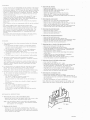
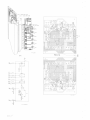
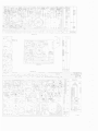
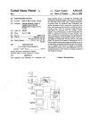
for receptlon of black-whlta and colour transmltters operatlng according to CCIR-PAL standard.
Aerlal match-tng
Convergence
tr'ocus strng
I. F. lumlnance
I. F. sound
75 O
magnetlc
electro- statlc
38. I MHz
32.9 MHz
F"M sound
6,0 MHZ
I. F. chromln[utce
Subcarri.er
Malns voltage
Power consumptlon
Band I
Band III
Band IV +
(WIF)
(VHF)
V (LIHF)
470 47
1-74
34,47 MHz
4.43 MHz
220 - 240 V
280 W
68 MHz
230 MIlz
890 MlIz
s)
604 PURLEY WAY . WADDON. CROYDON . CHg 4DR
TELEPHONE: 0l-686
0505
(Recorded messages after business
hours)
TELEX: 262308
Index: CS27062-CS27074, CS26984, CS26985, CS27075
Subject to modification
4822 727 L0525
csz7062
Printed in the Netherlandg
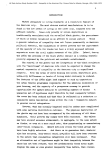
WARNINGS
.
.
.
.
.
.
3. Removlng the chassls.
As the chaesls ls llve lnde@nddnt of the posltlon of the malns
plug the set shcrld be connected to the rnalng vla an lsolatlng
trangformer (approx, 500 VA) wben the rear panel ls removed.
Due to the htgb tenslon (ca. 25 kV) the valves ln the HT cage
produce a certaln amount of X-radiatlon. However, when the
cage ls closed the screenlng ls so effectlve that the X-rays
ca:mot leave the cage.
To prevent that the set can operate wlth opened HT cage a
safety swltch has been provlded whlch lnterrupts the 92
voltage for the llne output valves. Thls ewltch should never
be closed or shunted when the cage ls open.
After repalr ensure tlat all Bcrews tn tle ltd are properly
tlghtened.
Never replace valves or components whlle the set ls svltched
- Hlnge out the chassls.
- Remove the plugs A,B,C,E,F,H,L,M -T-2.
- Remove the prlnt of the plcture tube.
- Unsolder the two earth leads.
- Detach the suspenslon cord from the chassls.
- Detach the H. T. -cable from the plcfure tube.
- Llft the chassls out of the two hlnge polnts and remove lt
from the chassls.
4. Removlng the control
-
on.
U6e safety goggles when replaclng the plchrre tube,
When replaclng valves or other componenta ln the HT cage,
removlng the chasels and replaclng the plcture tube, ftrst
short-clrcult the residual charge on the plcture tube. For
thls connect a properly lnsulated wlre to the chaesls and
hold the other end agalnst the H.T. connectlon for a few
seconds.
Be careful when meagurlng the voltages on the tube Bocket.
The focusslng voltage (on potnt 9) ls approx. 4.5 kV,
-
5. Removlng the push-button unlt
-
Remove the plugs X and Y.
Remove the three flxtng screws.
Remove the push-button unlt.
6. Replaclng the hrnlng potentlometers
-
Remove the push-button unlt.
- Remove the cap from the push-button unlt.
- Unsolder the leads from the defectlve potentlometer strip.
- Bend the tag wlth whlch the strlp ls flxed, upwards.
- Replace the strtp wlth the potentlometer.
REMARKS
1. The osclllogtams have been measured under the followlng
condltlons.
7. Replaclng the p. c. board of the band swltch of U14
- Remove the hrnlng unlt from tlre set.
- Remove the screenlng cap and the polnter.
- Loosen the ftxlng screw from the p.c.board
a. For
the black and whlte sectlon a cross hatch pattern
has been used as lnput stgnal and for the chromlnance
sectlon a colour bar pattern.
b. The brtghtness contrl,
lcrob 3, at normal brlghtness.
Imob 4, set to 4 Vp-p on the
c.
panel
Remove the cover from the convergence panel.
Remove the convergenee panel from tire set.
Remove wlth a long screwdrlver.the two screws from the
under- and the upperslde of the control panel.
Remove the slx larobs (volume, tone , etc. ) from the front
of the set and remove the control panel backrvards.
The contrast control,
control grtd of the vldeo output valve.
d. Saturatlon control larob 5, set to 40 mV p-p on the base
of TS439.
e. The hue control, lcrob 6 ln the mechanlcal mld-posltlon
2. The dlrect voltages have been measured as follows:
No aerlal slgnal, minlmum brlghtness, maxlnum contrast
and saturatlon.
The voltages ln the chromlnance sectlon marked wlth an x
have been measured wtth the colour/black-whtte swltch ln
posltlon 'rcolour" and the collector and emltter of TS443
lnterconnected.
a blank pattern ls required when the PM 5507 ls used,
thls pattern can be obtalned by means of the ralnbouw
slgnal, the vldeo knob turned fuIly clockwlse and the
black/whtte-switch of the set turned to posltlon blacVwhtte.
4. Integrated clrcult TAA550 (U414) mounted on p. c. board
8, ls avallable ln varlous verslons under one code number.
-
-
8. Replaclng valves ln the hlgh-voltage cage.
- Flrst read the warnlngs.
- Remove the cover from the H. T. cage.
- Loosen the serews fixtng the top plate, a few hrrns; push
3. If
These verslons are malked as follows:
a. Red or yellow palnt dot.
The Zener voltage ls between 30 and 33 V.
Thls I. C. may be marked as follows:
No code number or code number 30 on the houslng of
the I. C.
In this case the brtdge wlre should be fttted tn parallel
wtth Rl513.
b. Green palnt dot :
The Zener voltage ls between 33 and 36 V.
Thts I.C. may be marked as follows:
Code-number 33 on the houslng of the I. C.
In thls case no brldge wire should be fltted ln parallel
of the band
swltch and pull the p. c. board outwards. (Attentton! Do
not damage the contact sprlngs. )
Write down the colours of the connectlng wlres and unsolder them.
Connect the new p. c.board and place lt ln posltlon,
carefully ltftlng up the contact sprlngs.
Reftt the polnter and adjust the helght of the p.c.board
so that the polnter can move unhampered.
9.
thls plate upwards. Consequently, the PD500 ls algo
movlng upwards so that lt can be easlly removed.
Push the valve of valve holder GY 501 sllghtly upwards
so that the top connectlon of thls valve can be removed.
Now the valve can remove from the holder.
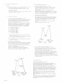
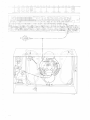
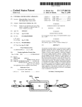
Removlng the convergence colls
-
Remove the multlpole plugs
- Insert a thln screwdrlver
-
N,O, and P.
tnto the mlddle opening (Flg. 2)
and carefully press the screwdrlver downwards.to dlsengage
the locklng pln.
Now the convergence coll can be wlthdrawn.
Note: When the coll ls lnserted agaln lnto the holder, one
should hear the holder cllcktng ln the openlng of the coll.
wlth R1513.
MECHANICAL INSTRUCTIONS
1.
-
Remove the screw from the upper slde of the cover to the
left of the rear panel, and remove thls cover.
Note: The c(nvergence panel ls provlded wlth explalnlng
slgns to facllttat€ converglng. The numbers lndtchte
- the sequence of converglng.
2. Hlnglng out the chassls
- Remove the rear panel and, subsequently, the nylon
-
locking pln from the rtght-hand upp€r slde of the chassls
Push the plastic locldng plate on the rtght-hand urderslde
of the chassls to the rtght.
Fig.2
csz 7063
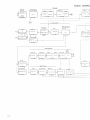
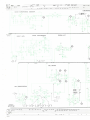
BLOCK DIAGRAM
SOUND
s526,527
B
-Y-001
GR163
TS 121 ,
/oatr.e
L22,L23,L58
TS 521
U5540
- 8402t
U554
I
I
i
tE_AMp.
B
B-P-002
GR160
-S -001
B
-S-005
B
cHRol
DETEc
-C-010
/oarcz
LUM INA
N
CE
GR459, /,70
U
536o,
B
U
,L72,L73
TS/,25, L27,L28,L29
553 b
-L-007
B/,01, 416t
U536c
LUM.IF.AMP.
IF. AMPLIFIER
U562 od,o
OETECTOR
CHROM. IF. AMP.
u1l.'17
I
B-C-010
B-r-007
BURST
B-L-008
AMP
I
I
U553o
B-C-015
B
- L-010
H OR
IZON TA L
U589
e
GR 495
TS
/.52, 453
PULSE AMP
6R /.90, /,91
8408t
8408p
Bl.10,t'11,u2
8L13, L1L
PHASE DISCR
B-T-002
B-T-003
B
-T- 008
TS /.3/.
TS 426
EMITTER FOLLOWER
( L uM.)
B
TS15r 6R488
INTERFERENCE
B
VERTICAL
-T-007
-T-007
SUPPR
TS455
PULSE
B
AMP.
-T-007
TS
456
6R
496
AUT. FIELD SYNC.
B- C-012
8116p ,
L17
T597
TRANSDUCTOR
B-L-009
BURS'
io,ra*,",*
OCK DIAGRAM
CHROMINANCE
TS/.36
IE-A
CHROM.
MP,
DE
T
/ tstls
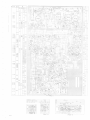
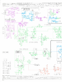
The lay-out of thls block dlagram follows the lay-out of the
clrcult dlagram as closely as posslble.
CHROM. AMPLIFIERS
ECTOR
B
-C-011
B
Wtth the aid of the numbers of the valves, unlts, etc. stated
above the blocks, the relevant sectlon of the ctrcult dlagram
can be located eaeily. The numbers below the blocks lndlcate
-C-012
the chapter of the SERV-O-MECUM ln whlch the worldng of
these clrcuits ls descrlbed.
U562
od,of,oi,op
TS 435
U
563
k
U
REACT CIRCUIT
- ---1suB.osc
suB oscrrL.
CHROM. AGC.
TSI.I3,LLL GR479
563 n,t,
R 1215
I
COLOUR KILLER +
AMP
"WHITE" SETTING
WHITE SWITCH
:
B-
C
U553e
B-C-016
-0i5
B-C-017
B-
_
C-018
B-B-007
CH ROM. VIDEO
TS
4/.7
GR
185, /.86
u578 i.f
8403,10/., 405
BLUE LATERAL
R1299/ | R 1307
STAT. CONV,
CONV.
(R-Y)AMPLIFIER
BEAM CURRENT
TS /.3/.
TS
SETTING
t L\,Ll.2 GR 493
B
COLOUROIFF.
-C -012
+
MULTIVIERATOR
DC LEVEL SETTIN6
B- C-012
B-B-009 r
B-B-009
AMPS.
B-
B-007
HOR
CONV.
VERT. CONV
TS 445
B-C-012
B-B-002 |
(B-Y)AMPLIFIER
B-C-013
B
-C-0
B-C- 029
GR 198
499,500
B-B-003
R1315
/
R1323
12
I T V 2/.16
v7 841
R 1125
R1126
s 598
TD 5/.0
R
2o
A
2b
6.tlt,
1o
Q
1338
u 578
n37
R 1303
1b
-
1336
lDENTIF.T,SkHz
SK9
u s62
R
ao o1Z:rL
4b
Or|rs
5o Sr5rs
o tlrc
8o Or!r,
sb orlre
6o Q t5rt
sb
R1298
G2 Blr!
u536
R
o
o
v5L7
u572
3/,,5 MHz
@e
R
33,1 MH z
1050
sl(10
(R-Y)'+(a-v)'l+
Oo
R1307
u 569
u 553
(R-Y)'+
+*
€
(g-Y)'
R
R1306
1055
SATURATION//CONTRAST
u 552
R
TD 570
997
5,5 MHZ
@t$v
1
330
32.? MHz
KONVERG.
Fig. 3
cs27065
1299
SK8
R1258
R909
+25
s 598
8 L1L
PD
Y
r03
I
G2 8119
B
419
R1299
l
72
R
1215
R1307
HOR. SYNC
R 1207
R1212
BALANCE
B 41 AlBA11
2
Fig. 3
s6o4
5OO
A
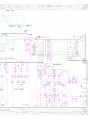
ADJUSTMENTS
t-
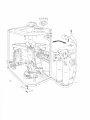
Adiustlng for a stralght ptchrre (see Flg.3)
Sllghtly loosen screw B. T\rrn the complete deflectlon
unlt stlghtly to the left or to the rlght untll the plchrre
ls stralght.
Ttghten screw B agaln.
2
Focuslng (see Flg.
of U589 so that the entlre plcture ls
as sharp as posslble at hlgh brtghbress.
3
Dynamlc convergence (see Flg. 4)
Remove the cover ln
Pln-cushlon correctlon (see Flg. 3)
z.
Wlth the atd of 5598 and Rl292 make the horlzontal
llnes at the top and bottom of the plcture as stralght
as possible.
b. Wlth the atd of R1179 make the vertlcal llnes ln the
mlddle of the plchrre as stralght as posslble.
Start by checklng ild, lf necessary, readjustlng the statlc
convergence (see polnt ?a and 7b).
Use a crossl'hatch pattern, swltch off the blue gun wlth
Vertlcal llnearlty (see Fig.
If the centre horlzontal green and red llnes lntersect, turn
the core of S604 (see Flg. 3) untll the llnes are parallel
as far as posslble or untll they colnclde.
Slttch on SKll.
lcrobs 7a, 7b and 7c (only lf the convergence strongly
devlates): start wtth the lsrobs ln the mld-posltlon.
Make the central horlzontal blue llnes as stralght as
posslble.
. Wlth
. Srvltch off the blue gun (SK11).
. Wlth lonob 3:
Adjust so that the horlzontal red and green llnes are
parallel over the entlre plcture wldth.
Horlzontal llnearlt (see Flg. 3)
Thls ts adjusted wlth the core ln coll x of U589.
3)
a. Devlatlons over the full plchrre helght are corrected
wlth the ald of R1273.
b. Devlatlons ln the top of the plchrre are corrected wlth
. Wlth lmobs 4a and 4b:
Adjust so that the central vertlcal red and green llnes are
parlllel over the entlre plchrre helght.
. Wlth lmobs 5a and 5b:
Adjust so that the dlstance beiween the horlzontal llne
palrs (red + green) ls equal over the entlre plcture helght
ln the mtddld of the screen.
the ald of R1284.
Plcture helght (see Ftg. 3)
Thts ls adjusted wlth R1266.
7.
StatLc convergence (see
. Wlth
Flg.3)
Use a dot or cross-hatch pattern.
a. Swttch off the blue gun wlth SK1l, see Flg. 3.
Make the red and green patterns colnclde ln the centre
of the plcture by means of lmob la and knob lb. Thus
a yellow pattern ts obtalned.
Srrltch on the blue gun agaln.
b. Adjust lmob 2a and 2b so that the blue pattern and the
yellow pattern colnpl$e in the centre of the screen. As
a result a whlte pattern ls obtained.
Note: If no satlsfactory result ls obtalned, lt ls posslble to lnterchange the termlnals S1-S2 of the -blue lateral
untt, see Fig. 3.
Centrlng (see Flg.
3)
a.. Wlth R1290 the picfirre carr be shtfted ln the horlzontal
dlrectlon.
b. Wlth R1289 the plcture
can be shlfted ln the
vertlcal
dlrectlon.
Colour purltv (see Flg. 3)
Allow the set to warm up for approx. 20 mlnutes. Apply
a blank pattern slgnal. The room should be as dark as
posslble, brlghtness and contrast should be set to normal
llght lntenslty. Slltch off the green and blue guns by means
of SK8 and SK10 respectlvely.
Loosen the four wlng nuts A a few firrns and sllde the
deflectlon coll as far as possible forwards or bac}ilvards
untll the red blur on the screen ls as small as posslble.
After thls the red spot ls centred as well as posslble by
means of colour purlty rlngs C.
After thls the deflectlon coll ls slld back untll the entlre
screen ls unlformly red. Subsequehtly, check the blue
and green colour purlty by flrst swltchlng on only SK8
and then only SK10. When after thls SK8, SKg and SK10
are swltched on slmultaneously, a unlformly whlte plcture
should be obtalned. Thls plcture should contaln no blurg.
If lt contalns blurs, correctlon to some extent ls posstble
by sllghtly hrrnlng the colour ptrrlty rlngs and/or sllghtly
movlng the deflectlon coll. After thls the three colours
should be rechecked lndivldually. Tlghten the wlng nuts
agaln.
If no prqper result ls obtalned the complete procedure
should be repeated.
For checklng the landtgg of'the electron beams on the
phosphor dots,use can be made of mlcroscope tlrye 800/
MLS, ordertng number 4822 395 90041.
csz?066
front of the convergence panel.
SKll.
3)
Set potentlometer ap
10
lmobs 6a and 6b:
Adjust so that the dlstance between the vertlcal llne palrs
(red + gleen) ls equal over the entlre plcture wldth ln
the mlddle of the screen.
. Cary out red and green statlc oonvergence (see polnt 7a).
. Wlth lmobs 7a, 7b and 7c:
Adjust so that the central horlzontal blue llne and the
correspondlng horlzontal yellow Ilne are parallel over
the entlre plchrre wldth.
.
Wlth lorobs 8a and 8b:
Adjust so that the dlstance between the horlzontal llne
palrs (blue and yellow) ls equal over the entlre plcture
helght ln the mlddle of the screen.
. Statlc convergence (see 7a and ?b).
. Wlth lmob 9:
Adjust so that the dlstance between the vertlcal ltne
palrs (blue and yellow) ls equal over the entlre plchrre
wtdth ln the mlddle of the,screen.
Note: If no satlsfactory result ls obtalned lt ls posslble
to lnterchange the termlnals R1-R2 of the blue
lateral unlt, see Flg. 3.
.
Statlc convergence (see point 7a and 7b).
11 At the back of the set above the addltlonal
loudspeaker
socket there are the knobs R, G and B (Rl302-R1298
and R1306 respectlvely) behlnd the cap on the rear panel.
Wtth these knobs the background colour can be adjusted
accordlng to the wlshes of the customer.
ADJUSTMENTS AFTER REPAIRS
1.
2.
IF-AGC
10. Trackln of saturatlon
Contrast and sahrratlon controls to maxlmum.
Connect an oscllloscope to 7M05; measure and note down
HF-AGC
the peak-to-peak value of the colour slgnal.
Connect the oscllloscope to 7 8401; measure and note
down the dlfference ln voltage between the black and the
whlte level.
Reduce thls voltage wtth the ald of the contrast control to
Z/S of. the value measured.
Connect the oscllloscope again to 78405 and adjust R1055
to 2/3 of the voltage measured at thls polnt.
Thls clrcult ls only operatlve at very strong lnput slgnals.
If the plcfure of a local transmltter ls dlstorted, adjust
R997 so that the plcture ls undlstorted.
3.
Horlzontal tlme base (use a cross-hatch pattern)
a. Connect junctlon C785/R1170 (M7) to chassls.
Adjust U587 so that the plcture ls stralght.
Remove the connectlon between junctlon C785/R11?0
and chassls.
Connect bTS453 to chassls.
Adjust Rl162 so that the plcture ls stralght.
Remove the connectlon between bTS453 and chassls.
b.
4.
Booster voltage (a) and booster dlode current (b)
(use a cross-hatch pattern)
a. Connect a valve voltmeter (range 1000 V d. c. ) between
junctlon C860/5590 (r'-'r) and polnt 10 of U589 (Ml0).
Adjust Rl207 to 550 V meter deflectlon.
b. Connect a valve voltmeter between 9B410 (M8) and
3B411 (M9).
Adiust Rl203 to 0 V meter'deflectlon.
Check the voltage under a agaln and, lf necessary,
correct lt.
Note: The booster voltage should be aceurately adjusted
to the value speclfled and should never exceed thls
value.
Also take lnto: account the tolerances of the measurlng
lnstrument used and ensure that the mains voltage does
not devlate.
5.
and contrast (appty a colour slgnal)
Adjust R1003 for ma:rlmum nolse ln the plcture (no stgnal).
11.
@
(e. g.
after replacement of plcture tube;
use a blank pattern)
Set the
colour swltch SK3 to posltlon black
a^nd
whlte.
Use another set of the same type as a reference; thts set
should be connected and adjusted ln the same way.
Allow both sets to warm up for approx. 10 mlnutes.
Adjust the cut-off polnt of the new plcture tube (see polnt 6).
If requlred, correct t};re 92 flne adjustments (R1298, R1302
and 1306) untll the llght lntenslty of both tubes ls the
same (at low brlghtness).
Next, set both hrbes to a hlgh brlghtness. If the whlte
oolour of the new hrbe devlates, the cursors A, B and C
of sllde potentlometer R1215 (see Flg.3) should be adjusted
untll the whtte tones of both tubes are approxlmaterly
the game.
If the sllders A and B of sllde potentlometer R1215 have to
cross each other, the jumpers V2 and V3 on the plcture tube
prlnted panel can be soldered ln the other positlon.
In both sets remove SV3 and connect the pln of SV3 on the
p. c.board to the +25 V (junctlon R9L4/R905 on prlnt 5).
Now eqtrallse the white colours wtth cursor D.
Rernove the lnterconnectlon and reflt termtrral SV3.
Beam current llmttatlon (use a plaln whlte and synchronlzed raster)
Brlghtness and contrast to maxlmum.
Remove jumper across R1213 (wlre support on hlgh-voltage cage).
Connect voltmeter across R1213 and adjust for 0.1 V
wlth F"L2]-2.
Subsequently, brlghtness and contrast to mlnlmum. The
meter readlng should now be 1. 3 V (t 0. 1 V)
Reflt jumper across R1213.
Check the booster voltage. For any eorrectlons see
polnt 4a.
6.
Cut-off polnt of plcture tube (use no aerlal slgnal)
Remove slngle plug from p. c. board 4. (CRT-base panel)
R1298, R1302 and R1306 (g2-flne adjustment) to mld-
posltlon.
Make the room as dark as posslble.
The potentlometers mentloned below should be adjusted
so that the screen just remalns dark.
R1299 for the green gun (swltch on SK8 and swltch off
SK9+SK10 ).
R1303
for the red gun (swltch on SK9 and swltch off
SK8+SK10 ).
R1307 f.or the blue gun (swltch on SK10 and swltch off
SK8+SK9).
reflt the slngle plug.
Apply a black /whLte test pattern from a transmltter or
a generator, and vary the brtghtness from hlgh to low
wlth the brlghtness control.
Lr so dolng, the grey hue should not change. Correct any
devlatlons at a low level of brlghtness by means of larobs
Swttch on SK8 and SK9 and
G,
R,
(Rl
7.
and B.
29 8
, R130 2 and R130 6).
+25 Supplv Voltage
Connect a voltmeter between the collector of TS421 and
chassis.
Adjust R909 so that the meter readlng ls 24.6 V.
8.
Vertlcal tlme base (use a cross-hatch pattern)
Short-clrcult RL246.
Connect an 8.2 M0 reslstor between the cursor of R1258
and 28416.
Adjust R1258 untll the plcture ls statlonary;
Remove the short-clrcult and the 8.2 M0 reslstor.
9.
Vertlcal output stage
Connect a voltmeter between 784L7 and chassls.
Adjust Rl280 to the voltage value lndlcated on the chassls.
csz 7067
(J
TRIMMING INSTRUCTIONS
B. THE CHROMINANCE CIRCUIT
Note s :
1.
1.
2
Durlng trimmlng the T. V. set should be connected to the
malns vla an lsolatlng transformer (500 VA).
The measurlng equlpment should be properly earthed.
The IF chromlnance detector (see Flg. 3)
Set the band swltch to posltlon UHF an apply an unmodulated 36.8 MHz slgnal of approx. 10 mV to the IF
lnjectlon polnt on the hharurel selector (see polnt 2
under |tNotestt).
Apply a dlrect voltage of 5. 5 V between junctlon
R100s/Clat (test polnt "M2") and chassls (ff-'' to chassls).
Connect a valve voltmeter (posltlon 10 V d.c., negatlve)
to polnt 1 of U554 (test polnt ttlU,.f.z9rr) and adjust core I'in'r
Applvlng the IF-slgnal
Apply the IF-slgnal vla 1000 pF capacltor to polnt G of the
VHF channel selector (prlnt 8).
of U554 for mfurlmum deflectlon.
2.
A.
1.
The IF st
es
* lumlnance detector (see
at
40. 9
to posltlon UHF and apply a wobbu-
polnt on the \IHF channel selector. Apply a voltage of
5.5 V between junctlon Rl003/C681 (test polnt rfM2")
and chassls (tr-r' to chassls).
Connect an oscllloscope to polnt 1 of U554 (test polnt
Flg. 3)
to posltlon UHF and apply unmodulated
IF slgnals of approx. 10 mV to the IF lnjectlon polnt on
the VHF channel selector (see polnt 2 under "Notes").
Turn the contrast control to ma:r.
Appty a dlrect voltage of 5.5 V between junctlon R1003/
C681 (measurlng polnt 'tN'.I?rr) and chassls ('r-rr at chassls).
Connect a valve voltmeter (posttbn 10 V d. c. negatlve)
to junctlon S45I/C654 (test potnt '?M3"), arid adjust the
cores mentloned below for mlnlmum meter deflectlon.
"frfr of. 1J552 at 30. 9 MItz tt
rfef
of. U552 at 30. 9 MHz x
of. 1J552
IF bandpass curve
lator slgnal of 36 MHz (sweep 10 MHz) to the IF lnjectlon
Set the band swltch
rrlil
Checklng the
Set the band swltch
LUMINANCE CIRCUIT
f
rM29 rt).
The curve should be as shown ln Flg.8.
38,9MHz
MHz x
rfirr of U552 at 40.9 MHz x
rdil of U553 at 33, 1 MHz
rrdrr of U536 at 33,1 MHz
rfe'r of U536 at34,5MHz xtr
U551 at 32.7 MHz
f
x Cores 'et' and ttj, of U552 are hollow and are located
at the top of the coll can.
Coll 'ff'f and tflfr are accesslble by means of a trlmmlng
f
key through the hollow cores
xx
rferr
and
36,8MHz
rrjrr.
For adjustlng thls core flrst lnterconnect the collector
emltter of TS443.
33.1MHz
25x
and
,
Checklng the
IF bandpass curve
>500x
of the VHF channel selector. Apply a dlrect voltage of
5.5 V between junctlon R1003/C681 (test polnt ttMz'?) and
chassls (rr-rf to chassls).
Connect an oscllloscope to polnt 1 of U536.
The curve should be as sho'urn ln Flg. 7 . When the
collector and the emltter of TS443 are lnterconnected,
the dotted curve of Fig. ?, should be obtalned.
I
I
2
\\
3.
M
Hz
>500 x
30,9MHz
to posltlon UHF and apply a wobbulator
slgnal of 36 MHz (sweep 10'MHz) to the IF lnjectlon polnt
Set the band swltch
/'0,9
41,5 MH z
Fig.8
>70x
The 4.43 MHz chromlnance-ampllfler, see Flg. 3
Pull out the IF cable at the bottom-left on the chassls
Turn the saturatlon control to max. and set black-whtte/
colour swltch (SK3) to posttl-on "colours'f .
hrtercormect the collector and emltter of TM43.
Connect an oscllloscope (prosltlon AC) or valve voltmeter
wlth frequency range up to 6 MHz to the collector of TS439.
Apply an unrnodulated 6 MHz slgnal (approx. 10 mV) to
polnt 1of U55A (test polnt I'M29rr) vla a capacltor of
2200 pF and adjust core I'bf f of U558 for mlnlmum ampllhrde,
Now apply 15,5 MHz slgnal and adjust core t'err of U558 for
mlnlmum amplltude.
38MHz
C.:SOUND SECTION
35MHz
The 6 MHz sound sectlon (see Flg. 3)
\
38,9MH
z
t
33,1 MH z
> 320x
?l),--13!,17MHz
-Y 10x
-
3
0,gMHz
>500 x
Fig .7
4o,gMHz
,500,
41,5 MH2
>70 x
P'rlI out the IF cable at the bottom-left on the chassls.
Apply an unmodulated 6 MHz slgnal (approx. 10 mV) to polnt 1
of U554 (test polnt rrM29") vla a 2200 pF capacltor.
Connect a valve voltmeter (pobttlon 3 V d. c. posltlve) to
junctlon R975/C665 (test polnt "M5t'). Turn core 'h, il' of
U547 a quarter turn antl-cloclsrdse (the meter glves a readtng
of approx. 1 V) and adjust ?tf , g" of U547 for ma:r. meter
deflectlon. Subsegrently, connect an 820 Q reslstor between
polnt 3 of U557 and chassls and adjust rreff of U557 for max.
defleetlon.
Remove the reslstor from polnt 3 and connect lt between
polnt 9 of U55? and chassls and adjutst "c,d" of U557 for
max. deflectlon.
Remove the reslstor and adjustth,lt'of U54l to a deflectlon
of 0 V.
Subsequently, apply a 30 7o modulated AM stgnal and adjust
rralrf of U547 for mlnlmum ouptt voltage on test polnt rtM5rt,
to be measured by means of an oscllloscope or mllltvoltmeter"
csz
706 8
n
D. seECIFIC SHRoMINANcE ADJusTMENTs
1.
(see Fig.3)
The sub-osclllator
Apply a colour slgnal and adjust the recelver to normal
setttng.
Connect an oscllloscope to polnt 9 of U563 vla an attenuator probe (10 :1 ) .
Connect junctton 5561 /Caaa to chassls and lnterconnect the collector and emltter of TM43.
Adjust ''ab" of U563 for mlnlmum amplttude on the oscll=
loscope.
Remove the oecllloscope and adjust "ff ' of U563 so that
the colirur pattern ls practlcally statlonary.
2,
F is.11
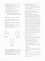
The ldenttflcatlon clrcult
Apply a colour slgnal and set all controls of the recelver
to thelr normal posltlons.
a. By means of a slngle-beam oscllloscope:
Connect an oscllloscope to the collector of TS434
(measurlng polnt M23) and adjust 5556 for murlmum
amplltude (about 20 V p-p). Remove the oscilloscope
b. By means of a double-beam oscllloscope:
Connect the "beam A" lnput to the collector of TS434
(measuring polnt M23) and the "beam Bf ' lnput to
junctlon C732/C?33. Adjust S556 so that the Ilne
pulse colncldes wlth the maxlmum and the mlnlmum
value of the ldentlflcatlon slgnal (see Flg.9).
Remove the oscllloscoPe.
F
i9.12
When Flg. 10b ls obtalned, adjust R1103 so that Flg. 10a
arlses. Subsequently, connect the I'beam Arf lnput to
the collector of T5445 (test polnt 'rM18) and adjust the
horlzontal ttme base so that 2] perlods arlse (see Flgs.11
and 12). In these figures the sectlons lndlcated by means
of the clrcle are essenttal. Dlsplay one of these sectlons
on the oscllloscope by settlng the horlzontal amplltude
to x5 (lf necessary, use Xshlft). The oscllloscope rnav
now show one of Flgs. 13.
Fig
3.
9
The colour AGC
- Appty a colour slgnat and set all controls of the recelver
to thelr normal Posltlons.
- Connect a valve voltmeter (1n;poslttron 10 V.:) to
jrrnctlon RL029/R1031 (measurlng polnt M"25rr) and
adjust "h,1" of 1J562 for mlnlmum meter readlng
(about 5 V).
Remove the voltmeter.
Fig.13o
Fig.13b
4a. The dela Ilne TD570 (wlth PM 5507)
Apply the ralnbow slgnal from the PI\{5507 and adjust
the recelver to normal settlng. Connect the rrbeam Bil
lnput of a double beam oscllloscope to junctlon Rll04/U575
(test polnt I'Ml9") and adjust the horlzontal tlme base
so that three perlods are dlsplayed (see Flgs.lOa and 10b).
F ig .13c
Fig.13c
Fig. 13d
- If Flg. 13a ls dtsplayed both for the B-Y'
F ig. 10o
(Flg. 11) and
for the R-Yt slgnal (Flg.L2\, the amplltude and phase
of the delay llne are correct and no further adjustment
ls necessary.
- If Flg. 13b ls only obtalned for the B-Yt slgnal, then
adjust V572 so that Flg. 13a 1s obtalned.
Flg. 13b ls obtalned both for the B-Y' and for the
R-Yt slgnal, then flrst adjust the core (crosshead) of
U569 so that Flg. 13a ls obtalned for the R-Yt slgnal
and adjustcUl72 so that thls td also obtalned for the
B-Y I slgnal.
- If
Flg. 13d ls obtatned, flrst adjust.R1060 so that
Flg. 13b ls dlsplayed, Rrrther proceed as descrlbed
ln the precedlng sectlon.
If Flg. 13c ls obtalned, adjust R1060 so that Flg. 13a
ls dlsplayed.
- If
Fig.10 b
csz7069
-
4b. The PAL dela IlneTDJ?q(wlth PM5506 or PM5508)
Set the generator to posltlon "Delay". Set the contrast and
the brlghtness to thelr normal posltlons, and set the
saturatlon control to 3/4 of tts range.
- If the thlrd bar shows the I'Venetlan bllnds?' effect,
5b. The sub-osclllator
and the burst- hase dl scr lm lnator
(wtth PM 5506 or PI\4 5508)
Set the geDerator to posltlon rrPhaseI and set all controls
of the receiver to thelr normal posltlons.
a. Adjust I'aerr of U563 unttl the lower part of bars 1 and
2 ls practlcally equal to the upper part of these bars.
b, Adjust t'vrrof U562 untll the Iower and the upper part
of the thhd bar are equal.
c. Repeat the adjustments mentloned sub a) and b) until
the Iower and the upper part of the flrst, the second
and the thlrd bar are equal.
elemlnate thts wlth R1060.
- If the flrst and second bars show the "Venetlan
-
bllndrr
effect, ellmlnate thls wlth U569.
to posltlon 'Colorlr Barr'.
the fifth bar.from the left (cyan and
magneta respectlvely) shows the I'Venetlan bllnds"
Set the generator
f
Il the thlrd or
-
effect, ellmlnate this wlth U572.
Set the generator
6a. The
to posltlon "Matrlxr'.
elimlnate thls wlth R1103.
Note: For photographs of the I'Venetlan bllnds" effect
reference ls made to the Dlrectlons for Use of
the colour pattern generator (PM 5506 - PM 5508).
5a. The sub-osclllator phase
trAdjustments after repalrsr'.
Apply the colour bar pattern from the PM5507 and tune
the recelver carefully to the hlgher sldeband.
Turn contrast and saturatlon to maxknum and brlghtness
to mlnlmum. Set the hue control to lts mld-posltlon and
the black-whtte/colour swltch to rtcolour". Turn the
vldeo control of the PM 5507 to maxlmum. Connect an
oscllloscope to polnt 12 of 8419 (B-Y stgnal) and adjust
rrolr of U577 to 150 V,
@eak-to-peak value). By means
of the saturatlon control decrease thls value to half
(75 V), then by adjusttng "oil of U577 lncrease lt agaln to
150 V.
Next adjust, ln turn, the contrast,brlghtness and saturatlon controls for a normal plcture. Wlth the vertlcal
amplttude control of the oscllloscope adjust the peak-topeak value of the slgnal to 4 blocks. Measure the peakto-peak value of the voltage at polnt 11 of 8419 on the
oscllloscope and note lt. Next adjust the amplitude control
of the oscilloscope so that the peak-to-peak value of the
voltage at polnt 2 of 8419 corresponds to the value noted,
Connect the oscllloscope to_polnt 3 of B4t9 (R-Y slgnal)
and adjust "o" of U578 to 2{ blocks. Then connect the
oscllloscope to point 6 of 8419 and set the amplltude
control of the oscllloscope so that tle peak-to-peak value
ls the same as that prevlously noted.
Swltch off the red and the blue gun (wlth SKg and SK10
respectlvely) and set the black-whtte/colour switch to
rrblack-whlte". Adjust the brlghtness control untll the
green bars are just vlsible, then set the black-whlte/
colour swltch to rtcolourrr. Adjust R1125 so that on the
screen the 6th green bar from the rlght (there are 10 ln
total) just looses lts brlghtness. Connect the oscllloscope
to polnt 7 of 8419 (G-Y sfgnal) and adjust R1126 so that
the peak-to-peak value ls 1.4 blocks.
a
Check adjustments 1,2 and 3.
Apply the ralnbow slgnal from the PM 5507 and hrrn
contrast and saturatlon to ma>rlmum.
Connect a valve voltmeter (posltlon 30 V d. c. , posltive)
to polnt 3 of U562.
Apply a dlrect voltage of 5 V between junctlon R1029/
R1031 (test polnt ttM25") and chassls ("-f'to chassls).
Adjust th,1" and rrvil of U562 accurately to mzuctmum
meter deflectlon.
Remove the dlrect voltage and the valve voltmeter.
Interconnect polnts 4 and 5 (test polnts 'M16" and rMlTrr
respectlvely) of delay llne TD570.
Connect the Y lnput of an oscllloscope to polnt 3 of 8405
and the X lnput to polnt 3 of 840 3.
The oscllloscope now shows elllpses accordlug to one
f
f
of Ftgs .L4.
6b.
Fig.1l,b
Fig.14 o
R-Y/B-Y demodulator and G-Y matrlx (wlth PM5507)
Check successtbely the above adjustments 1,2,4a
and 5a then adjustments 5-6 and 11 under the headlng
If the red bar shows the "Venetlan bllnds" effeet,
The R-Y/B-Y demodulator 4nd the c-Y matrtx (wlth
PM 5506 or PM 5508)
Thls adjustment can only be reallsed with the aid of the
modlfled I'Colour Bar" test pattern; in thls case the
upper part of the pattern ls made up cf colour bars and
the lower part of a white area. If thts should not be the
case. flrst refer to the converslon lnstructlons Cd 583
for generators PM
-
Fig .11,c
-
5506 and PM 5508.
Check successlvely the above adjustments 1,2,4b
and 5b, then adjustments 5-6 and 11 under the
headlng trAdjustments after repalrsrt.
Set the generator to posltlon "Colour Bar",
Adjust the contrast and the saturatlon to maxlmum
and the brlghtness to mlnlmum.
Set the hue control to mld-posltlon.
Cormect an oscllloscope to polnt 12 of the picture
tube (B-Y slgnal) and ailjust for 150 Vp-p wlth preset
I'orr of U5?7,
Adjust the saturatlon control untll the voltage ls reduced
to 100 Vp-p.
- Adjust tlreset" "o"
hr these Flgs. one elllpse ls lndlcated wlth an lnterrupted
llne and one wlth an unlterrupted the.
Adjust the vldeo amplltude of the PM 5507 so that approx.
2.5 V ls obtalned ln the Y dlrectlon.
- If Flg. 14b ls obtalned, adjust ttvtt of u562 so that the
two elllpses preclsely coyer each other as shown ln
Fig. L4a.
adjuet traerf of U563 tuttll
the two elltpses colnclde (see Flg. 14b) and then adjust
fv" of U562 untll Flg. 14a [s obtalned.
- ff ftg.L4c ls obtalned, flrst
f
csz7070
of U577 agaln to 150 Vp-p remove
the oscllloscope.
- Swltch off the red and green guns with SK9 and SK8
reepectlvely. Adjust the brlghtnese, the contrast and
the saturatlon so that there ts no dlfference ln brightness between the four blue bare, and the tlue lower part
of the screen.
- Swltch on the red gun and swltch off the blue gun. If
requlred, a,iLiuiit ilrcset "oi'of IJ578 si;i;hat there ls no
dlfference ln b::1::ht;res: l:etrvct-'rr the four red bars and
the red Irler pirrl ol. the scrceil.
- S{.ttch on the glr:en grrn ard sq'itch rrlf the red gun. If
necessar]', adjrisr H1125 and Rli26 so that there ls no
dliference in brlghtness between the four green bars
and tht-; icrwcr grc*ln part cl the screen.
- Swltch on the r-ed and thc green gun agaln.
- Check adrrstment 5b.
pos.1
: L822 /,66
10184
pos 2 1 1822 290 80186
PRINT
x2
<-
{{X5
Y6
X1
{r
X3
-lF
Y5
+
TTV 2O60
A
8
,'tTl1
\\-\
'.,tgt*rll. -I___l\_-__
IAt
r
t
rAis
\\"
>'l
TTV
2
/.59
N
\-(={-:
w
K
ttg
nz
1
B, TS, GR
m
o
PRINT
PRINT '!3
1
811
832 937
648 860 818
836 843
850
829 838
833
812
846
853 8l.L
TS156
6R496
IS L23
TS 455
B /.16
831 831
828 845
8s6
855
826
825
821
857
T
596 Bt
17
8s2
6/.6
600
800
I
913 912 905 S1r 907 908 906
910
799
909
1?10 121? 12t 3 12t 6 1253 1252 12r,5 1250 \218 1219 1279 1266 1?51 1251127 31?651211 1210 1256 1277 125?
\237
128c
1211 1238
\218
1235
]269
'lr'80
1285
1267
1258 1259
12'lL
1?16
PRINT
TS 122
GR 459
TS 421
851
-
c
1261
S,T,U BJS,GT
5
598
PRINT 6
l2 l8
12
r9
t31l
1223
r310
1292
122L
1222
861
864
1220
1228
r30 3
962
1301
865
122?
5l,L
r300
1297
r295
1215
1299
PRINT 4
1307
R
GR4g1
GR490
PRINT
8408 GR/.81
GR461
GR468
101'1 911
898
899
1165 1163 1164116? 117011751162',1171 11721113118211791176 1178
1288
1290 1289
901
1'181
r
896 895
',1192
203
11851195
897 9',t6 892
1206
1208 120'.t
GR/.66
s 529
903
890 900
891
118/. 1191 119/. 1168 1196
120t
S
GR/,62 GR49/. GR495 GR45{, GR{,63
s528 5604
u587
T 597
c
2
1121
B,TS,G
S, T, U
904, 800 -'1099
1100-1199
1118
129/,1293 12091212 1295 1210 1211
1286
1200-
1397
R1286
'l'16
'l9L
PRINT
3
795
781
?89
798
799
782
792
797
783
788
791
785
't7g
?86
'18'l
793
?t7
ffiffiF
-*'{.ffi&
r:'!ii'li
+3
700
I
r.,..
li
---
799
I TV 21,65
R
=-\_.BLlL
PRINT
.t
^1,4r
i"'u^*L
-R8etl
56.58,60.?0
--l
L
I
I
l1fu
.t, 'ri]l
PRll-,T
;;
I
I
I
I
L_--_
b5
b6
b7
b10
b11
b8
TT V 2469
TS{,26
610
503o b c
TS1400 rS/.31 TS451 GR461 GR462 rS452
GR 488
TS432 TS453 GRt,75
TS455 GR463 TS{5€: GR468 GR464 TS456
u1l,1l,
u1416 S526
51i
678
d
621 620 622 612 523 680 613
765 760 766 757
= 619
624o
684
525 681 682
b c
s528
T 586
689
685
627
683
628 630 637
778
775
761
8410 -/.11 _- _--112
TT?
I JJ.
__--L1t
?T
J."L
-11',7 -1,',16
-401-/.04-403-405-402-408
828
826
825
GR{,90
GRr
U553
638 639 629
782 787
776
I
827
SUPPLY
?T
.J- 4
+31
1.1v
fJU
:"s !fl'-&aJd-'
4V
c 880
c szo SLB'
ter
TS 458
4zKIGRL61
c609c
2K2
R
c509d
2K2
GR /.60
t
13/.3
6R 463
xBY 127
55?8
BAI(t
c
,K
o
tx
rl
2
A
ut4
i,,"[_rl
ce
zall
:il?i
c529 -g,gV
GR 16{,
=
!tooopr
8Z Y88
c9v1
R 890
1l
+20
200v
GR/,68
BA I(8
TS 1400
'BC1t8C
t
IF-AMPLIFIER
R
1/"60
u 552
l*
l.J-
=^
*| 1K7
I
-.
c 5s5
c 689
T,,,
11K
7
['
n
5
'-l
tl
tc
l*
b
aftsi
wl
I
LT
,
c 681
_-l
H'
ok
lox
[IHF
-
-w-[-
nl
-toK
Trcx'
-l
tly__J
3)v
3
ir'r,
-
l,xlT
R995
tv
TS431
8C
+21
148C
roo3
l-fc582
c eeo
A-
R
't002
I
]o
GR
!75
"y,rtr,
-
Rroo6
+25
x
997
R
1004
R
998
AUT-GAI
N
,rurrrr{\r/\1,,
2v
CONTROL
-U
R
994
l,3v
-U
c7?8 Rtl63
a
t50K
Rt16?
SYNC. SEPARATOR
R
rt5
+?q
7 76
i,lllfilHliliilllfii4'i R
GR(9'
I
n
,
.)
+ ''. 7 ctss
. rr
.^.lt
52
t7
115115,1
TS 4
8C 1{,8
)
crrol ii*
rzo
TS4 53
BC
147
5%
o,sw:llfi
5%
c 761
10%
row
+ |
5o/o
I
Rlrsl
I
I
{}
0,25w
{-l-
lw
{i
2w
-f]
: lUfi
5Yo
1C%
<2"2Mn.
>
2,2M5?
I
I
I
282
S
't0%
s,sw :i33fi
I
:t!'u",
5%
ln o/
tv /d
5%
:{F- {,oov {}!{F- socv fiF
1r11--
\
DC
o,12sw
%
BAX15,
c7't5
AC
---+:---
-il[}
/3(
0,2v
\
-€:f-
t
R
1'l 58
1't55
r\Y;[
--->--
585
5a/o
R
t?1"!
c7 66
:A
JE
Be l5B
tJv
J
oR 488
-llvR
soov
oa 90
soov
roov 3{}- rooov
c76i
R
Ir 50
ri.s\
828
lo
121
lax
c 167
:A
c 836
(7/F7
,00
+26
SUBJECI
TO MODIFICATIONS
886 88? 889 888 884 922 924 9s3 992
bUU -
999
CD
it>!
I
200
-68v
I
115?
1450
891 8s2 893 895 89? 896
99/. 995
996 997
1151 r150 11r,6 11r,9 11r,5 1111
11,61
ll62
1457
1456
k 58
1460
1398
1657
998
11.53
899
898 901 I 11
1152
1154
1000
1r,55
1
510
It5a
- 1006
1155
1158
1513 1238 1?31 12t
1
i2L2
13t
',]213
3.1348 1397
1?
/.6
1215
I
t
TS t
630
u 536
537
638 639 62s
643 6/,4
785 786
612
778 '.t76
782
781
833
83/.836 837
.
STAB
840
VO LTAG E
A
1(8
rf
4V
c
aI,ce rt
JTT
.-643
,K
SOUN D
2
843
gt,t,
848
C6LL
(70.p F
c
3o
o0K
DETECTC
U5L1
-
+25
t1K
t1 0Y
SOUND
L
u557
- -_-_l
I
oof
BF 195
8C r07
c646
;5.l5lTsL22
851 852 806 807 800 801 853
845
m
TS4?3
R
909
AC128101 7
6
B4
t-
R
Tttzl
U5L7
-IF-AMPLIFIER
91(
BZY 88/C1s
2s,3v
I0x2
/.67
GR
8t
+26
,8V
-
EIF
8 4',10 B 411
795 797 798 799
841
c768 o
tTyFl
n
903 c61?
tK
25
s 537
R 1153
GR 466
v
1.t
650
768 791 ?89 191 't9*
880
u 557
549
R
6(8
at
910
r-
I t00p
F
L
+20
200v
LUMINANCE-DETECTOR
+25
u553
-1
b
o
8F195
I
C1
8F 197
I
1
652
lC 651
.FrF
l17yF 14K7
l" r
J
o
v
5,8V
6,6V
/
R/
/l
2
9
8F 196
V
9?6
eE2
ocl
i," ,,t
6,5
R
I
.,H
921
.12
+25
I
r$.t
R
9;0
l13l
oo
r;-l txo t-;l loo
n
e2?
-d|
i6E8
J.
R9
t,sv
@
1s6
2s,,
<VTl,,
i
_.llit
tri,L\,^
HOR. SY NC
T
c778 Ril53
a
c eos
t0K
c795
6
,K
.6R490
r.
BAX16
L
81,11
\
.!
27
*f
t00
c776
PL 504
a
c 788
a lt
820
t00 K
-F
c798
\..,r?o
c 800
-I9
6
)
R
18
K
il
tl
c ?9r
I
I
/(ft,
I
ll
ll
3tl J
io'" lij,?,,
.L.Ll
'.';lEJ
c 793
+
aK7
I
t__
ll
]L
I
I
I
I
Y
l
VERT OSCILLATOR
VERT. SY NC.
-\\
L
1i._T
! \-_t
Rl?55
uo,, V ERT OUT PUT
I
I
'20K
8(1
c
t'{F
oF16r |
R
1
250
R
c 811
l?5r
270
oi
x
R
1?5i
I
"?,[!J
c838
T,i,,
c834
c 832
t a
t
J 3K
l
1'0K
i;;7
-c833
R
125?
ltooK
1C837
lR56
i;,-i'ar
t12
c
j{}
8(0
8K2
c865
t:ll-
c 841
t'{}
c 8r.5
{}R -0,5V
22K
127
1
J9K
o;
22K
2
903
'r162
)48 139?
1?
t
3
1?
r.6
12
-
r165
L5
1168
il67
90/.
1170
-
905 907 906 908 909 910 912
1250
9r3
',r21,9
r251 1252
1253
1254
920 921
9u,
1175 1176 r1?9 r178
1171
1153
1181 1182 1185
1256 1257
118/.
1261 1258 1259
69
57
63
1022
1260
1186 1194 1195
1264
1191 1192 1188
1189
1213 1265-1261 1204 1203 1269 1211
66
67
928
931 935
S33
119?
50
12',7A
12',t1 121112nn11202121612181280
812',10
I
71
1i
TSt25
B
/.10
Lzl
IS
84',]1
GR/.69 TS 428
T 596
TD
U5L7
851 852 806 807 800
t
B 415
TS 521 GR,{70
GRt,8t
31,13
Giir,91
GR472
540 S590 S541
5543
U5B9
s545 T597
654 655 656 659 667 665 566 668 657 658 669
859
801
5598
s 54/,
660
670
671
r
663
GR,173
5/,9
6't2
GR
495
s 515 S 516
662
86"
+25
Acl
Y
SOUND DETECTOR
SOUND
-AF-.AMPLiFIER
c 655
17K
{,
LU M I NAN CE
4-^_32 b)
- AM PLI FIER
lla*
Itt
66
r63
D/
llf
fll"ilLillrrfliLi
)\Ir
TD 51,0
l2v
trt
\
840'l
R
9 59
'1Pt802
J
1l
22
R945
;tiA-
5,8v
TSt27 o
6V
8C
5 8v'
6_
c556
,
e{F
R
s
1s9
+
c660
fiy Eapr
220
5{,1
1/
^t
r'/'
R
917
R
9C i48C
x
934
R96f.
K
c 659
'5'lFl -+.-A
R930./
R
929
|
'
EF
t80
-Z4V
8416t
GR470
r
GR{'72
\
957
R
941
I
,/
}ruu
Y
,/
iii^,,,yya(
R
2,tv
I
oAgr
9/.9
t,5v ljtRI.69
'1il,f-
X
R
953
+-.-r
s0l
81i
E H.T
HOR
fll
OUTPUT
l--
hran
30v
x
12
T
c aoo
c 800
IA
L
BL12
100 K
.F
t0K
00
PY
5OO
8411
=ll
PL 504
;l
t)
tt,.|
GR(95
BAX16
I,.l
7
h
ll
f\-I'
T
ll l26ovi2ocv
Ll t
_Jt___l
L
,ronl I
80{,
A
I--i
LIT
K2
i
F
63,2132 +
Of,=D.rl r
r{l--'-,----
<-_
26 30,
.C 60, 6i,62i
l
soov v ERT
OUT PUT
481
I
863
e
BA 1&8
I
2V8
_t__
c85516
(70T|
-
C
85
7lo
170
-.5Cv
R!
250 v
c853
I
e$
I
I75V 5r(sf
I
I
b6
5K5
L
d
c96
c 856
I-r
t
?r'
(
I
f80v I
l\
l_:\]---J-
t
l\
e 859
20 0&0yF
-(
4
L^
5
r3c
10 33,35
18, 39 41
-{--
l8
39 8
1269 12?r r2?0
1271 121l1279:2a1vozn'n:27B2ar
60 8 12 't0
I
'11
1206 1208
1207
l2aL noo
3105
ac
6'i,62,90,9'l
{'r
9
97
I
lrc
L
---
t:so+
1395
fm-ngr rssalzSs
1286
1292
1288
rzsor2Tf-
1210
1
t822 727 1808.4
noa-ru1,
129: r:ao rflz
K7o (B-To)
| 1199
urr rZs5l 1200-
IS. B.GR
GR /.77
TS 434
5T.U
600 699
c 700 799
s 561
s 556
688
TS
ss8 696 -Oga
693
LLz
u 562
485
GR 483
692
591 690
GR
s
u 558
u554
486
559
436 TS /.45
575 S 573
TS
U
697
702
706 721 7t1
u565
',t23
KT 502
705
800-
CHROMINANCE
CHROM. A.G.C.
'!
ili
s----{-F
I,I
ri
llI l,tx
ri
ti
ll
l'
,,1,ilil
?0
PAL
PAL
18
SWITCH
IDENTIFICATION
\
I
?6 30 32,
33. 36 38,19,40.
{,1. 60. 61.6? 80
10.
.*---!>
Mj,,,
81
r0r3 1014 1015
1,47,,, Jl--lL/,' "Lt-T
r08? 1093 1089 1096
l09l
"'L}J
1088 1092 1097 1098
1023
1095
1106 'tl0?
1103
1102 1101 11001099 1030
fizL
1025 1026
1029
1075 1076 1081 1090 1082
1031 110/. 1036 1035
1033
436 TS /./.
u575 S 573
GR4/.5 GR/.48+450 GR/.92 GR522 B/,03 TS439
TS
2
706 '.tzL
7t
us6s
1
u578 U577 U553
KT 502
711 709
723
u 567
712 713
?10
GR/.79 GR523 g{,05
s 568
RE 5I8
708
715
8404
750
756 752 75t,'118 753
757
731755713?/,17t5 721
1t-9117
813 +816
+2s
DELAY LINE
SK3
i
?T
su,
i
-l,UUlJl,l,-l
I
I
i
+25
I
I'
i
I
I
I
I
COLOUR
i
K
ILLER
I
I
I
I
I
I
I
I
I
I
I
I
','tt}*! ,'W','fuilA\
I
I
t,
V
52
54
70
AMPL.
R-Y
ir rs" | *'
ll
Bi
.e,
i
i
;
OU
r
i.e,
"
i ",r,:.
.7"'
i\*.:
i.-r,,jt.
$-r
jlfi- td__" I
'i. ;
-, zo-i--*
,,,"
t,",
f'
1n
I,TI
mn
i'[a;ro-*\ 840/.P
v,',,
"o**l I ^
G-Y
ffinlo')'
i-.J i
i
r
+=-+
.!o i
iiL,l
iic..i.-, I I
i r
- i --'I
-i
'}i i;j
i
. i .i\
-.NF-i ,'ix
i
I
I
!,
J
I
I
15
"
I
i:i,li
ii:rrai
2,
)t(
L
1035
i
;
GR 523
BZY88/C7vs
ilio
i,
-
I
|
'
tl|
:
,
D
!i
1104
I
__A{,ssirn=
I
I
1076 1081 1090 1082 1033
i
l-l
I
,-----*-tI--{
lt
'';J .{
*
I
n,,7
l. ^'''
i
n
B
i.a
*Y NFn
ETH|";
-*--1019 1038 1039 1040 -
I
1046
'1050
104
8
1054
-
i
,"|-tflJtIL;
]
,,Eo
./sl
1
0
5?
.'140+
1035
Ctt
]121
1143
1122
10/"9
1125
1130
i126
1131 1115 1113 112? 1052 1053 1070
r135 1139 1111 1043b 1063
10?1
1382
76 8/. 85
86
't]
19 1t
81
20 21
1112
1116
1061'
1119 111/. 1058=1060
22
-
1068
1120 1121
DELAY LINE
c0L0l..,R
otl
r;}l
,
Rt 22C
+5K
2
tov
iu.l,
TS
2C.'tt.r
RXZ?3
-='
1,,5 k V
l"
il'iilt6
I
I
B
I
R r215
I
lc
v1
I
I
+25
I
I
'e
KILLER
I
L
#-r, -f1r'/','FIAA\
+3
?
)L.,._
iil
c 8?7
220 K
_. *
i,:2"2
VERGENCE
u593 k
R
'12
lR
i
CO N
96
r22'l
ei
in
il
.p'
^!
,I
i
1
B
BEAM
/'04t
CURRENT
PC(F) 2oo
1112
119
1116
',l'11/. 1058-
1064
-
1060
1073 10?L 1077
1058
1'120 1121
1296
-
1299
1300
-
1303
1215 1218',1219 1291 1222 1220
r30? 1306 1310 1311
27
28
1330 1333 1329 1331 1338 131,1 13?5
13?? 1332
26
TTV 2&59
n
-A
/r'l\
lEl
T597
s598
s600
s601
s602
s603
s604
l---l
\c/
840r.
B4O2
B4O3
F,4O4
8610 5
B4O B
841 0
B4r 1
B4L2
841 3
8414
8416
B4L7
841_9
GR495
GR496
GR498
GR499
GR500
GR522
PL802
PCLB6
PC F2OO
PCFzOO
PC F20 0
PC FBO 2
PL50
VL5O 5
VL5O 6
BV5I2
Printed board
PD500
PC F8O
PLsO
8
-
120
X
s5l_5
s516
-
4
4
{t
- 16
CI
RE5l_ 8
@
s525
BC 148C
s528
s529
s530
s531
u536
s537
TD54O
s541
s543
s544
s545
U547
T549
u551
- UK
u552
u553
u554
s556
u557
u55 8
s559
u562
pi
u565
u567
GR446 BAX16
GR448 BAX16
GR449 BAXl6
GR45O BAXl6
GR459 0F161
GR46O F-YL27
GR461 RYJ.27
GR462 BYL27
GR46:] 8A148
GR464 BZYsB/ C9V1
GR466 84148
GR46 7
BZY88/ Cl8
GR468 84'148
GR469 BAXl6
GR47O OF161
GR47 2
04.91
GR47 3
0F161
GR47 5
0F161
GR477 BAX16
GR4?8 BZY}g/C?V5
GR47 9
0A91
GR481 8,{148
GR4B3 OF161
GR485 04.90
GR486 0,4'90
GR48 8
04'90
GIT4gO BAX16
GP.491 BAX16
GTt492 0F161
tlP,zlj{ BYX10
u569
TD57O
71-
240
240
280
157
4822 157
L0007
30066
70093
50308
10006
4822
4822
4822
4822
4822
157
158
158
2L0
L57
50308
10101
10101
20L56
50624
4822
4822
4822
4822
4822
r57 50652
253 30027
253 30027
466 t0L44
2L2 20063
157
L57
157
157
10034
10042
10007
10007
4822 2L0
4822 140
4822 154
4822 2L2
4822 2L2
20L86
60184
50133
20034
2005L
210
158
154
L54
4822 158
20158
20184
40039
30029
10251
L57
156
2L8
157
156
L0045
10332
24042
10007
10332
4822 157 10011
4822 L56 20493
4822 2r2 20038
s573
u575
u57
4822
4822
4822
4822
4822
4822
4822
4822
4822
s568
s5
242 70L4t
4822 L56 202L2
4822 2L2 20049
4822 2L2 20037
4822 L54 90027
4822 153 90025
s561
U563
4822
4822
4822
4822
4822
4822
4822
4822
4822
u572
+$-
ul.4l'4
BZY88/C7V5
KT5O2
py500
cy501
TS421 ACl28/Ot
BCT47
T S42 2
T S4tZ iJ
BC 10 7
T5425 BCr_49
TS426 8C148
TS427 8C159
TS428 8C159
T S42 9
BC148C
TS431 BC148C
TS432 8C149
T S434 BC 14 78
TS43 5
BC148C
TS43 6
8F 194
T 5437
BF195
TS43B 8F195
TS43 9
8F194
T 5441
BC 148
T5442 BC148
TS443 BCi77
T5444 BC 148
Br'19 5
T S44 5
T5447 8F1.95
T 5451
tsC 148
T 5452
BC 14 8
TM53 8C147
TS455 BCr_48
TM56 8C158
TS45B AC128/A1
TS521 BCI ?jc'tr's1400
0 F161
9
PL504
A66
BAX16
0F161
0F161
0F161
7
2r2
u578
4822
s585
4822 157 10008
T 586
4822 157 40109
4822 156 10044
4822 140 10107
4822 rzt 40L93
4822 122 50033
u587
U589
ab
ad
l-w
af
10 kpF
100 kpF
50 pF
6CI
aJ
ao
ap
AS
30 M0
500 ka
39 kCI
at
au
N. T. C.
e
8Y176
f
g
h
t
x
z
s590
u591
u592
U593 a-h
t-
j-k
T 596
48L2
4822
4822
4822
4822
20038
LzL 40L92
113 90046
111 70103
101 20365
rL}
20L49
4822 252 60002
30065
30588
10102
10102
4822 116
4822 130
4822 158
4822 158
4822
4822
4822
4822
4822
158 10102
157 50583
L50 50027
L57 50592
158 10082
4822 150
4822 156
4822 150
4822 L50
4822 140
20015
30278
10076
200L2
20036
4822 152 30075
4822 L56 20484
4822 156 40495
4822 156 40496
4822 156 20546
4822 157 50585
4822 L57 50239
4822 130 40463
- TAA550
ilR886
R887
R888
R891
R892
R895
R896
R897
R900
R901
R904
R905
R909
R911
R914
R916
R929
R941
R958
R960
R969
R976
R981
R985
R987
R988
R995
R997
R1000
R1001
R1003
R1019
R1026
R1043
R10 50
R10 55
R1060
R1103
R1111
R1113
R1115
R1125
R112 6
P"Lt27
R1130
R1131
R1135
R1139
R1162
RLl 79
R1197
R1199
R1203
R1206
R120 7
R1210
RL2L2
R1215
R1258
R1266
RL273
RL274
RL279
R1280
RL2B4
R1289
R1290
Rr292
R1298
R1299
100 0
100 fi
V. D. R.
4, 7 Q
4, 7 {l
4822 116 40006
4822 116 40006
4822 116 20081
4822 113 80121
4822 113 80121
150 A
150 A
5, 6 I
390 a
33 A
L/e
4822 115
4822 113
4822 113
4822 11_1
4822 111
10031
90044
90045
50166
30004
r/2 w
4822 111
4822 r1l
4822 100
4822 113
4822 111
30011
50346
10036
90043
50193
330 0
22 I
4K7 St
680 CI
220 A
L/8
100 CI
10 k0
1K2A
L/4 w
3K3 A
27 St
t/4 w
3W
470 CI
200 kO + 200 kCI
15
27
r/a w
0
10w
l<Sl
180
L/2 W
A
t/4 w
3K90
V. D. R.
220
CI
v. D. R.
v.
D. R.
4K7 0
120 kCI
470
470
l/a w
A
CI
L/4 W
2K2A
220 0
2k2 0
470 0
10w
10w
10w
10 k9
10 kS'
10
l<st
- 22 ldr
10 k0
10w
8K2A
12 0
68 A
82 A
82 0
t/+ w
1/s w
L/4 W
L/4 w
22 W
10 kQ
0,51 0
470 kCI
V. D. R.
100 ka
3k90
1 MA
1 MA
CI
V. D. R.
1 MO
100 kS'
+ 11
Q
7,5Q+7,5Q
47 0- 2W
470 kfit
2Nr2 A
111
116
100
116
116
30018
20063
10075
20083
20083
4822 100 10036
4822 110 60163
4822 100 10038
4822 101 10115
4822 11-1 30015
4822 100
4822 100
4822 100
4822 112
4822 112
10019
10029
10038
30134
30134
t'1
4822 112 30134
4822 100 10051
4822 100 10035
4822 LLz 30L32
4822 1l-1 30255
4822 111 30007
4822 111 3 0299
4822 111 30299
4822 100 10051
4822 100 10035
4822 100
4822 111
4822 116
4822 101
4822 101
1 kO
O
4822
4822
4822
4822
4822
4822 116 20003
4822 101 10027
4822 105 20013
4822 101 10019
4822 101 10019
V. D. R.
47 T<SI
11
4822 101 10069
4822 101 10116
4822 111 30027
4822 LLz 30145
4822 LLL 50204
4822 113 60088
4822 113 60084
4822 101 10068
4822 116 20038
4822 101 10022
10
220
4822 111 30343
4822 101 l-0118
4822 111 30316
4822 115 90077
4822 111 30003
10102
70006
20084
10019
10022
_^\
4822 103 10087
4822 103 20213
4822 103 10076
4822 LOL 20262
4822 L}L 20265
t
csz7a75
I
R1302
R1303
R1306
R130 7
R1315
R1316
R1318
R1319
R1320
Rl_321
RI322
RL327
R1330
R1335
R1336
R133 7
F,133 8
R1341
RL347
R1375
R1383
R1384
R1385
R1398
C610
C611
C623
C624
C625
C629
C639
C644
C648
C649
470
W
4822
4822
4822
4822
4822
2M2 {t
470 kO
2M2{2
330 0
330 CI
150 Q+
100 A
L20 A
L20 A
100 A
47
100
100
100
100
100
100
0
A
0
CI
CI
0
0
LOL 20263
LOL 20265
103 10079
2W
2W
4822 103 10079
150 A - 2W 4822 103 10081
2W
4822 103 10078
2W
4822 103 10082
2W
4822 103 10082
2W
4822 103 10078
2W
4822 103 10076
2W
4822 103 10078
2W
4822 103 10078
2W
4822 ln3 10078
2W
4822 103 10078
2W
4822 103 10078
2W
4822 103 10078
1K50
L2 0
35W
47 t<St
33 k0
Vew
Uaw
22
LOL 20263
LO]- 20265
A
560 ldt
L/+ w
L/+ w
c652
c 653
c 660
c672
c677
c682
c 685
c 691
c694
c 698
c 703
c708
C7L2
c 713
C7L6
c 718
C7L9
C72L
c735
c753
C755
C768
C820
C826
C833
C851
C852
C859
C860
C870
C871
C880
C881
C1431
C1433
CI435
kpF - 250 V
100 kpF - 250 V
400 pF
500 + 250 + 50 prF
16 pF - 300 V
pF
16 V
470 ttF
100 pF
33 irF
40 V
47 ttE
25 V
63 V
350 V
16 V
16 V
1000
4 trE - 400 V
4,7 1tF
8pF prF
120 pF
L20 pE
47 pP
47 pF
lpF
15pF
47 1tF
27 pF
33pF
82 1tF
47 1tF
47 1tF
250 ttF
1 t-rF
47 1.tF
500 pF 4 ttF 47 1tF'
5 kpF 4,7 ltF
33 pF
33 prF
16 pF 20.000 pF 1000 prF
330 pF
50 pF
4700 1tF
500 pF 1 pF
1 pF
47 pF
100
40 V
40 V
16 V
25 V
25 V
63V
63 V
25 V
25 V
60152
60147
50063
30181
4822
4822
4822
4822
4822
L2L 20068
LzL 20068
r24 40087
L24 40088
I24
20433
4822 r24
4822 L24
4822 L24
4822 L24
4822 L24
20417
20035
20407
20384
20366
4822 L24 2037L
4822 L24 20347
4822' L24 20066
4822 124 20385
4822 L24 20385
4822
4822
4822
4822
4822
r24 20385
L24
L24
L24
L24
2037L
2037L
20341
20357
r24 20371,
r24 20362
V
V
V
V
2,5 V
4822
4822
4822
4822
4822
L24
L24
L24
L24
L24
400 V
25 V
5000 V
63 V
4822
4822
4822
4822
4822
L24 20035
L24 2037L
124 20347
L24 2036.6
4822
4822
4822
4822
4822
L24
L24
L24
L24
L24
4822
4822
4822
4822
4822
4822
L24 4009L
r24 20428
L24 20408
40 V
300 V
2,5 V
16 V
16 V
30 V
4V
2,5 V
63 V
63 V
25 V
Push-button unlt Ut4
P. C. board of band switch UL4
Potentlometer strlp UL4
Contact holder of band-swltch TJL
I{nob 92 (flne-trurlng)
Switch SK3-SK11
110
110
110
110
L24 20366
L24 20379
L24 2037I
40 V
4822 459 20L28
4822 492 61398
4822
4822
4822
4822
25 V
25 V
25
25
63
25
Dlal wlndow of push-button unlt
Clamplng spring of p. c. board of channel
selector
Mountlng plate of control panel
Splndle of potentlometers (volume, etc " )
Matrs swltch SKL
Knob, volume , tone , etc .
4822 116 30087
4822 115 50129
4822
4822
4822
4822
4822
40V
4822 462 70698
4822 404 30051
4822 404 30052
4822 404 30053
4822 410 21068
Rear panel
Long spihdle of convergence lalobs
Strort splndle of convergence lcrobs
Convergence lmob, small dlameter
{F
100
Table protector
Cam securlng the chassls
Hinge of chassls
Cam securlng the rear panel
Push-button of m.alns swltch
2037L
20399
2034t
2037L
20024
r24 20067
20366
20433
40097
204L7
20403
L24 2034L
L24 2034L
I24 2037L
4822 459 602LL
4822 535 70345
4822 276 L0372
4822 4L3 30446
4822 2L0 40LLL
4822 466 10184
4822 101 90043
4822 290 80186
4822 432 10081
535 90678
535 90667
4L3 30448
691 10113
Convergence box
4822
4822
4822
4822
Slltch
4822 273 30t79
SK8-9-10
Knob of SK3-SK11
Caslng of deflectlon coll
Buffer rlng of deflectlon coll
Purlty rlngs
Sprlng securlng the purlty rlngs
4822 4L3 30*47
4822 276 10383
4822 410 21003
4822 691 10068
Red plug on convergence r.rnlt
Green plug on convergence unlt
4822 532 60438
4822 532 507L2
4822 492 6L342
4822 266 40029
4822 266 40031
BIue plug on convergence unlt
Coaxial plug M
Coaxial coupllng socket M
Plugs A-B-C-D-X-Y
Plugs H-L
4822 266 40032
4822 264 10036
4822 267 10036
4822 266 30055
4822 266 20045
Plugs
Plugs
Zq
E
4822 266 30054
4822 264 5005L
4822 492 60063
4822 413 40396
4822 255 70L47
-F
Holder of safety fuse
I{rrob, , focuslng
Plug holder F
Valve
Valve
Valve
Valve
Valve
holder, 10 plns, pertlnax
4822
4822
4822
4822
255
255
255
255
4822 255
holder, 9 plns, ceramlc
holder , I plns, pertlnax
holder, PL
508
holder of ptcfure hrbe
Valve holder PL504 - PL509
Valv6 holder GY501
Fllament wlndlng GY 501
-
Focus cable
HT-cable,with cap
PY500-PD500
7007L
70L39
70L0L
70097
70L42
4822 255 70044
4822 255 70L4L
4822 320 20043
4822 320 2004,5
4822 320 20035
Ring round HT-cable
Top connectlon PD 500
Safety swltch of HT-cage
4822 532 60307
4822 256 90066
4822 276 L0302
4822 2L0 40L04
4822 2L0 50064
Aerlal caslng, complete
4822 691 10143
Channel selector VIIF
Channel selector UHF
- U1416
- U1412
'ERVICE
15-4- 1 9? 1
NNATIO//I
K?0 CTV setg
Bk 41
a. S22K4e2/L6/56 - S26K497 /L5/55.
Modified: Channel selector U1417 - UHF - 4822 210 50064.
New version with built-in n+{ -filter 4822 zLB 20057.
b. General.
Modified line outprt stage, see Fig. 1.
8411 (PL504) has been replaced by PL509.
R1181 (2? kA) hae been replaced by a resistor of 47 kO.
Added: Rl180 (220 k0 - L/8 W) between 38408 and 88{08.
No longer uged: R893.
R899 (18 kO) has been replaced by a resistor of 1.8 kO.
In the filament circuit, Bl10 has been fitted in the place of B{11, and vice veroa.
RIl99 (1 Q),has been replaced bv a reeistor of 0.51 f2- 4822lfg 60088.
Added: D503 - D 504, BYL27, between 98410 ard 18410. erd between 98411
end 18411
Reagon: Reduction of diesipation of 8410 end protectlon of PL509.
c. General.
Modifted: Controls on gZ panel.
Control 92 fine tuniry wae 4822 413 3044?; hes become 4822 413 3043?.
d. General.
Modtfted: Blue and Green AdJuetment.
Added : R1312 - 8.2 kQ - L/4 W betweenpoint 2 of the picturetube and Junctlon
R1215
- Vl.
e. General.
Modlfied: R1209 hae beer. replaced by aafety regletor
Reason : Protection agair. t picture tube flashover.
f.
- 22 kf| -
4822 LLL
General.
Modtfted: R906 (470 0) has been replaced by a resistor of 680 0.
Reaeon : Improvement of stabllisatlon.
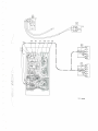
g. Generel.
Modtftcatlon brightneeB control, 8ee Fig. 2"
Modtfied : OF 161 (cR4?3) hee been replaced, by AAZ 17.
R971 (390 kQ) has been replaced by a reglgtor of 4?0 k0.
The supply voltage on R9?1 was +?. and has becmre '+3.
Added: R1108 - 1kA. R1109 - 68 Sl and R1110 - 2.2k92.
'Reason:De*eageYrt",frT,il,tffi
r
niltfi :t:$:il1""J""f,T?;;t:?"k,a*ons.
Copyrrght ror.rv.d. Confidrntiel informrtion for
Pdattd ia rhc
Nrrh{mdr
scrvicG"$tehrc CSZgg?S
BK L1
B/.1 0
PL 509
8Y127
a
R
1197
I
p1509
R
1199
R1202
1
F5
Fig
c663
A
+3
R
-21
961
R
R
971 .Y
967
\
1c662
+25
R
1110
-y
+ZS
R969
R1109
Rrlog
c3 Rl3Bo
Fi
c9299??
9.2
o
t\
{
hf
o
B3
13A