1
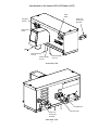
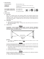
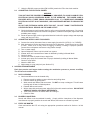
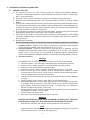
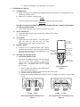
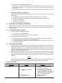
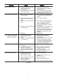
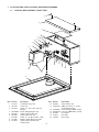
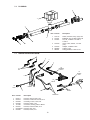
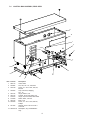
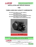
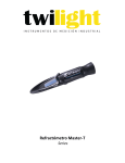
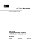
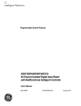
Check out the Lancer web site:
www.lancercorp.com
INSTALLATION AND SERVICE MANUAL
FOR
LANCER LEV® FILL STATION (LFS)
(PART NUMBER 85-0084-01)
NOTICE TO USERS:
THIS DISPENSER UNIT IS INTENDED FOR IN-DOOR USE ONLY.
This manual is an initial issue.
6655 LANCER BLVD. • SAN ANTONIO, TEXAS 78219 USA • (210) 310-7000
FAX SALES
USA -CANADA – 210-310-7250 • LATIN AMERICA – 210-310-7245 • ASIA – 210-310-7242
EUROPE – 32-2-755-2399 • PACIFIC – 61-8-8268-1978
FAX ENGINEERING: • 210-310-7096
"Lancer" is the registered trademark of Lancer • Copyright — 2001 by Lancer, all rights reserved.
REV:
P.N.
10/19/01
28–0510
TABLE OF CONTENTS
NOTICE TO USERS................................................................................................................................COVER
TABLE OF CONTENTS ......................................................................................................................................i
INTRODUCTION TO THE LANCER LEV® FILL STATION (LFS) ....................................................................ii
1. SPECIFICATIONS .......................................................................................................................................1
2. INSTALLATION ...........................................................................................................................................1
2.1 RECEIVING........................................................................................................................................1
2.2 UNPACKING ......................................................................................................................................1
2.3 INSTALLATION ..................................................................................................................................1
2.4 CONNECTING TO ELECTRICAL POWER .......................................................................................2
2.5 CONNECTING SUPPLY LINES TO SOURCES ................................................................................2
3. SCHEDULED MAINTENANCE ...................................................................................................................2
3.1 DAILY .................................................................................................................................................2
3.2 BIWEEKLY SANITIZING ....................................................................................................................2
3.3 EVERY SIX MONTHS........................................................................................................................2
4. DISPENSER CLEANING AND SANITIZING ..............................................................................................3
4.1 AMBIENT PROCESS .........................................................................................................................3
5. OPERATION OF THE LFS..........................................................................................................................4
5.1 CONNECTIONS .................................................................................................................................4
5.2 INITIAL POWER UP...........................................................................................................................4
5.3 AUTO MODE......................................................................................................................................4
5.4 MANUAL MODE.................................................................................................................................4
5.5 SETTING THE DESIRED RATIO.......................................................................................................4
5.6 CHANGING SYRUP PACKAGE PROCEDURE ................................................................................5
5.7 CHANGING THE BOX OF SYRUP....................................................................................................5
5.8 FUNCTIONS AND ALARMS ..............................................................................................................5
6. TROUBLESHOOTING.................................................................................................................................5
6.1 GREEN POWER LIGHT DOES NOT COME ON ..............................................................................5
6.2 UNDER SOLD OUT CONDITION, SOLD OUT ALARM SOUNDS, BUT THE
RED SOLD OUT LED DOES NOT FLASH........................................................................................6
6.3 UNIT WILL NOT GO INTO AUTO MODE ..........................................................................................6
6.4 SOLD OUT ALARM DOES NOT SHUT OFF.....................................................................................6
6.5 WATER NOT DISPENSING FROM VALVE .......................................................................................6
6.6 RED LIGHT ON CIRCUIT COMES ON OR GREEN LIGHT
ON THE CIRCUIT BOARD DOES NOT COME ON ..........................................................................6
6.7 WATER LEAKAGE AROUND NOZZLE .............................................................................................6
6.8 LEAKAGE BETWEEN UPPER AND LOWER BODIES.....................................................................6
6.9 MISCELLANEOUS LEAKAGE ...........................................................................................................6
6.10 INSUFFICIENT WATER FLOW..........................................................................................................6
6.11 INSUFFICIENT SYRUP FLOW..........................................................................................................6
6.12 ERRATIC RATIO oBRIX .....................................................................................................................7
6.13 NO PRODUCT DISPENSED .............................................................................................................7
6.14 WATER ONLY DISPENSED, NO SYRUP, OR SYRUP ONLY DISPENSED, NO WATER ...............7
6.15 VALVE WILL NOT SHUT OFF ...........................................................................................................7
6.16 EXCESSIVE FOAMING .....................................................................................................................7
7. ILLUSTRATIONS, PARTS LISTINGS, AND WIRING DIAGRAMS ............................................................9
7.1 CONTROL BOX ASSEMBLY, FRONT VIEW .....................................................................................9
7.2 PLUMBING.......................................................................................................................................10
7.3 WIRING HARNESS DIAGRAM........................................................................................................10
7.4 CONTROL BOX ASSEMBLY, REAR VIEW......................................................................................11
7.5 INTERNAL COMPONENTS .............................................................................................................12
7.6 WIRING DIAGRAM ..........................................................................................................................13
i
Introduction to the Lancer LEV® Fill Station (LFS)
Power
Switch
Power Cord,
Three Prong,
Grounded
LED (Red),
Sold Out
LED (Green),
Power
LEV R
Probe Assembly,
LO Level
Probe Assembly,
HI Level
Probe Assembly,
LO Level
Front View, LFS
3/8" Water Inlet
Power Cord,
Three Prong,
Grounded
Rear View, LFS
ii
3/8" Syrup Inlet
1. SPECIFICATIONS
SHIPPING WEIGHT
Nine (9) pounds (4.1 kg)
DIMENSIONS
14.5" x 5.5" x 6.5" (36.83 cm x 13.97 cm x 16.51 cm)
ELECTRICAL
115V/60Hz/1.0A
(Power Cord is provided with three prong grounded plug)
INLET SYRUP CONNECTIONS
3/8 inch Male Flare
INLET WATER CONNECTIONS
3/8 inch Male Flare
FLOW
4.5 ounces per second
2. INSTALLATION
2.1
RECEIVING
Each unit is completely tested under operating conditions and thoroughly inspected before
shipment. At the time of shipment, the carrier accepts the unit and any claim for damage must be
made with the carrier. Upon receiving unit(s) from the delivering carrier, carefully inspect carton for
visible indication of damage. If damage exists, have carrier note same on bill of lading and file a
claim with the carrier.
2.2
UNPACKING
A. Carefully remove unit from shipping carton.
B. Inspect unit for concealed damage. If damage exists, notify delivering carrier note and file a
claim against the carrier.
2.3
INSTALLATION
WARNING
DISCONNECT SLUSH MACHINE FROM POWER SOURCE BEFORE BEGINNING
INSTALLATION OF THE LANCER LEV® FILL STATION (LFS) TO AVOID POSSIBLE FATAL
ELECTRICAL SHOCK OR SERIOUS INJURY.
Base Fill Assembly
Screw Mounting, Hole Pattern
PN 30-3122
Figure 1
Mounting
A. The dispenser is designed for in-door use ONLY and to be mounted on unit, in a well
lighted, visible area.
CAUTION
FAILURE TO MAINTAIN PROPER AIR CLEARANCE WILL CAUSE THE UNIT TO OVERHEAT AND
WILL RESULT IN PREMATURE COMPONENT FAILURE.
B. Locate slush machine with approximately five (5) inches clearance between a wall and the back
of the LFS unit. Follow slush machine manufacturer’s installation instructions for side and rear
ventilation requirements.
C. If required, locate and mark four (4) holes using base of fill station (see Figure 1).
D. Cover hopper with lid before drilling holes.
CAUTION
ENSURE HOLES ARE CAREFULLY DRILLED TO AVOID DRILLING TOO DEEP AND THEREBY
POSSIBLY DAMAGING REFRIGERATION LINES.
E. Drill four (4) holes using a #19 drill bit (0.166) drill bit.
1
F.
2.4
Using the ROLOC screws provided (PN 04-0558), attach the LFS to the slush machine.
CONNECTING TO ELECTRICAL POWER
WARNING
THIS UNIT MUST BE PROPERLY ELECTRICALLY GROUNDED TO AVOID POSSIBLE FATAL
ELECTRICAL SHOCK OR SERIOUS INJURY TO THE OPERATOR. THE POWER CORD IS
PROVIDED WITH A THREE PRONG GROUNDED PLUG. IF A THREE-HOLE GROUNDED
ELECTRICAL OUTLET IS NOT AVAILABLE, USE AN APPROVED METHOD TO GROUND THE
UNIT.
DO NOT USE EXTENSION CORDS WITH THIS UNIT. DO NOT "GANG" TOGETHER WITH
OTHER ELECTRICAL DEVICES ON THE SAME OUTLET.
A. Check the dispenser serial number plate for unit's correct electrical requirements. Do not plug
into electrical outlet unless unit electrical configuration, located on serial plate, agrees with local
available power supply.
B. Route the power supply cord to a grounded electrical outlet of the proper voltage and amperage
rating, and plug in the unit.
2.5
CONNECTING SUPPLY LINES TO SOURCES
A. Connect free end of plain water lines to water supply [must be 30-110 PSI (2.1 to 7.6 BAR)].
B. Mark both ends of product and water lines and route to dispenser. Flush lines to be sure each
is clean. Failure to do so may result in clogging of valve(s), resulting in improper operation.
Connect lines to dispenser and secure using Oetiker clamps.
C. Turn on water supply.
D. Open all dispenser valves until air is bled from system.
E. Actuate valve until a smooth flow of water is obtained by holding in Manual Mode.
F. Check for leaks.
G. Connect free ends of product lines to bag-in-box.
H. Activate syrup pump until smooth flow of syrup is obtained by holding in Manual Mode.
I. Check for syrup leaks.
J. Adust the water flow.
K. Adjust water to syrup (ratio) brix (see Section 5.5).
3. SCHEDULED MAINTENANCE
Drain host product unit hopper before starting the sanitization process to prevent overfilling.
The LFS must be sanitized first.
3.1
DAILY CLEANING
A. Nozzle and diffuser must be cleaned daily.
1. Remove nozzle by twisting counter clockwise and pulling down.
2. Remove diffuser by pulling down.
3. Wash nozzle and diffuser with warm water. DO NOT use soap or detergent. This will cause
foaming and off taste in finished product.
4. Reinstall diffuser and nozzle.
5. With a clean cloth and warm water, wipe off all of the unit's exterior surfaces. DO NOT USE
ABRASIVE SOAPS OR STRONG DETERGENTS.
6. Taste each product for off tastes and/or brix changes.
7. Check for leaks.
3.2
BI-WEEKLY SANITIZING
Nozzle and diffuser must be sanitized bi-weekly. Comply with the instructions of the dispenser
manufacturer to properly sanitize the nozzle and diffuser, and ensure no off-taste is present.
3.3
EVERY SIX MONTHS
Clean and sanitize the LFS unit using the appropriate procedures outlined in Section 4 of this
manual.
2
4. DISPENSER CLEANING AND SANITIZING
4.1
AMBIENT PROCESS
A. The ambient process is the most common method for cleaning and sanitizing dispenser
equipment. The detergent should be caustic-based and the sanitizer should be a low pH (less
than 7.0) chloride solution.
B. Disconnect syrup containers and remove product from tubing by purging with water.
C. Rinse the lines and fittings with clean, room temperature water to remove all traces of residual
product.
D. Fill lines with a caustic-based (low-sudsing, non-perfumed, and easily rinsed) detergent solution.
The solution should be prepared in accordance with the manufacturer's recommendations, but
should be at least two (2) percent sodium hydroxide. Make sure the lines are completely filled
and allow to stand for at least ten (10) minutes.
E. Flush the detergent solution from the lines with clean water. Continue rinsing until testing with
phenolpthalein shows that the rinse water is free of residual detergent.
F. Fill the lines with a low pH (7.0) chlorine solution containing at least 100 parts per million (PPM)
(100 mg/L) available chlorine. Make sure that lines are completely filled and allow to stand for
ten (10) minutes.
G. Nozzle/Diffuser Sanitizing
Use the following procedure to sanitize the nozzle housing during dispenser sanitization.
1. Cleaning Solution - Prepare a low sudsing, non-perfumed, and easily rinsed detergent
solution and clean, potable water at a temperature of 90° to 110°F.
2. Sanitizing Solution - Prepare a chlorine solution (less than pH 7.0) containing 100 PPM
available chlorine with clean, potable water at a temperature of 90° to 110°F. Any sanitizing
solution may be used as long as it is prepared in accordance with the manufacturer's
written recommendations and safety guidelines, and provides 100 PPM available chlorine.
3. Cleaning Procedure
CAUTION
BE CAREFUL NOT TO GET SANITIZING SOLUTION ON THE CIRCUIT BOARD.
a.
b.
c.
d.
e.
Disconnect power, so the valve will not be inadvertently activated while cleaning.
Remove nozzle housing by twisting it counter-clockwise and pulling it down.
Wash the nozzle housing with the cleaning solution.
Immerse the nozzle housing in a bath of the sanitizing solution for 15 minutes.
While the parts are in the sanitizing solution, visually inspect around the nozzle
mounting area for syrup residue. Using a cloth or nozzle brush and sanitizing solution,
clean this area and the bottom of the nozzle body.
f. Wipe off the valve shroud assembly and any other areas that may have been splashed
by syrup.
g. Wearing sanitary gloves, remove, drain, and air dry the nozzle housing.
h. Make certain the nozzle o-ring is in place around the nozzle mounting area on the valve.
If necessary, slide a new nozzle o-ring (PN 02-0228) onto the nozzle mounting area.
(Wear sanitary gloves while handling the o-ring.) If needed, apply 111 lubricant (or
another FDA approved lubricant) to the o-ring.
i. Wearing sanitary gloves, install the nozzle housing by inserting it into the nozzle body
and twisting it clockwise to lock it in place.
j. Connect power and replace cover.
k. Reconnect syrup containers and ready Unit for operation.
WARNING
REMOVE SANITIZING SOLUTION FROM DISPENSER AS INSTRUCTED. RESIDUAL
SANITIZING SOLUTION LEFT IN SYSTEM COULD CREATE HEALTH HAZARD.
l.
Draw drinks to refill lines and flush the chlorine solution from the dispenser.
NOTE
Please note that a fresh water rinse cannot follow sanitization of equipment. Purge only
with the end use product. This is an NSF requirement.
3
m. Taste the beverage to verify that there is no off taste.
5. OPERATION OF THE LFS
5.1
CONNECTIONS
A. Attach 3/8” syrup hoses between syrup (BIB), syrup pump, and the unit. Inlet syrup hose, 3/8”,
attaches to left side of unit.
B. Attach CO2 connection to syrup pump.
NOTE:
The unit recognizes the left side of the unit as syrup and right side as water.
WARNING:
FAILURE TO RUN UNIT WITHOUT WATER LINES CONNECTED WILL RESULT IN OVERHEAT
OF THE SOLENOID VALVES.
C. Attach water lines from water source or prechiller to the unit.
5.2
INITIAL POWER UP
A. Insure the switches on the unit are set to the middle (OFF) position.
B. Plug in the unit.
5.3
AUTO MODE
A. Switch the unit into AUTO Mode. The Green power
light will come on and the valve will start
dispensing syrup and water out of the valve.
5.4
MANUAL MODE
A. Switch the unit in MANUAL Mode (this requires
holding down the switch). The Green power light will
come on and the valve will start dispensing syrup
and water out of the valve.
5.5
I.D. PANEL
(Shown in
open position)
COVER SCREW
FLOW CONTROL
WATER
FLOW CONTROL
SYRUP
Increase Decrease
SETTING THE DESIRED RATIO
Increase Decrease
A. ADJUSTING WATER FLOW
The Model 145 LEV® water flow may be adjusted
from 2.0 oz/sec (59.2 ml/sec) to 4.50 oz/sec
(133.2 ml/sec). The restricted flow adjustment plug
adjusts to a maximum flow of 3.3 oz/sec
(97.7 ml/sec).
NOZZLE (WITH
DIFFUSER INSIDE)
Valve Adjustment
Figure 2
1. Slide I.D. panel UP until flow control adjustments
are exposed (see Figure 2).
2. Remove nozzle by twisting counter clockwise and pulling down.
3. Remove diffuser by pulling down.
4. Install Lancer syrup separator (PN 54-0201, smoke, for Model 145 valves) in place of the
nozzle.
WATER
STEMS
SYRUP
WATER
OPEN
STEMS
Mounting Block Stems in OPEN Position
FIgure 3
4
SYRUP
CLOSED
Mounting Block Stems in CLOSED Position
FIgure 4
5. Activate valve to fill separator syrup tube.
6. Hold a Brix cup under syrup separator. Dispense water and syrup into cup for two (2) seconds. Divide number of ounces (ml) of water in cup by two (2) to determine water flow rate
per second.
7. To obtain desired water flow rate, use a screwdriver to adjust water flow control (see Figure
2).
B. ADJUSTING WATER TO SYRUP BRIX
The Model 145 syrup flow may be adjusted from 0.50 oz/sec (14.8 ml/sec) to 0.90 oz/sec
(26.6 ml/sec).
1.
2.
3.
4.
5.
5.6
Hold the Brix cup under the syrup separator and activate valve. Check Brix.
To obtain desired Brix, use screwdriver to adjust syrup flow control (see Figure 2).
Remove syrup separator.
Install diffuser and nozzle.
Slide I.D. panel (Valve Cover) down.
CHANGING SYRUP PACKAGE PROCEDURE
When a package of syrup is empty and the unit is in AUTO mode or MANUAL mode, the SOLD OUT
light will blink and the alarm will sound until a new package is replaced as described in the
following section.
5.7
CHANGING THE BOX OF SYRUP
A. If the ratio does not need to be changed:
1. Put the switch in the AUTO position.
2. The unit should be ready to fill in the AUTO mode again.
B. If the ratio does need to be changed:
1. Put the Switch in OFF mode and use MANUAL mode to dispense product as needed.
2. Follow the procedure to change the ratio (see Section 5.5).
3. Put the Switch in AUTO mode to go into AUTO fill mode. The unit should be ready to fill in
the AUTO mode again.
5.8
FUNCTIONS AND ALARMS
A. Probes monitor the level of product in the hopper if the level of product flows below the Lo
probes then the valve comes on and begins filling the hopper until contact is made with both Lo
probes plus an additional 17 seconds after that and then shuts off. If the level of product ever
comes in contact the Hi probe then the valve shuts off until the level drops below this probe.
(Applies for AUTO and MANUAL Mode.)
B. Sold out Alarm monitors the amount of syrup in the bag in the box when the level is low the
pressure switch activates and triggers an alarm and red led light which will blink. The alarm can
be turned off by replacing the bag in the box, changing the CO2 bottle or switching the unit in
MANUAL.
NOTE:
By switching the unit in MANUAL and then back into AUTO, you turn the sound alarm only OFF.
The red SOLD OUT switch continues to blink until one of the above is performed.
6. TROUBLESHOOTING
TROUBLE
6.1
Green power light does
not come on.
CAUSE
REMEDY
A. Unit not plugged in.
B. Loose connection.
C. Polarity incorrect (wires
crossed).
D. Failed transformer.
E. Failed PCB.
5
A. Check to ensure unit is plugged in.
B. Unscrew cover and ensure all
connections are secure.
C. Looking at terminals (LED away
from you), ensure flat side of the
rectangle (between the terminals) is
at bottom and that the red positive
wire is on the right terminal.
D. Replace transformer.
E. Replace PCB.
TROUBLE
CAUSE
REMEDY
6.2
Under SOLD OUT
condition, SOLD OUT
alarm sounds, but the
Red SOLD OUT LED
does not flash.
A. Loose connection.
B. Polarity incorrect (cables
crossed).
A. Ensure cables are secure.
B. Looking at terminals (LED away
from you), ensure flat side of the
rectangle (between the terminals) is
at bottom and that the red positive
wire is on the right terminal.
6.3
Unit will not go into
AUTO mode.
A. Loose connection.
A. Check to ensure cables plugged in
correctly.
B. Replace Switch.
C. Replace PCB.
SOLD OUT Alarm does
not shut OFF.
A. Pressure Switch is ON.
6.4
B. Switch is broken.
C. Failed PCB.
B. Failed PCB.
A. 1. Check Syrup supply.
2. Check Syrup Bag Line
Connections.
3. Check CO2 supply.
4. Check for loose connection.
5. Replace pressure switch.
B. Replace PCB.
6.5
Water not dispensing
from valve.
6.6
Red light on the circuit
A. Loose connection.
A. Check all connections.
comes on or Green
B. Bad solder joint or failed PCB. B. Replace PCB.
light on the circuit board
does not come on.
6.7
Water leakage around
nozzle.
A. O-ring is not properly installed A. Install or replace o-ring correctly.
above diffuser.
B. O-ring is damaged or missing. B. Replace o-ring.
6.8
Leakage between
upper and lower
bodies.
A. One or more retaining screws
loose.
B. Paddle arm assemblies are
worn or damaged.
A. Tighten all six (6) retaining screws.
Miscellaneous leakage.
A. Gap between parts.
A. Tighten appropriate retaining
screws.
B. Replace appropriate o-rings.
6.9
A. Water is not on.
A. Check water supply.
B. Chiller is clogged or shut OFF. B Ensure there are no leaks or clogs
in the chiller and that chiller is ON.
B. Damaged, missing, or
improperly installed o-rings.
6.10 Insufficient water flow.
A. Water flowing pressure is
too low, or restricted.
B. Foreign debris in water flow
controls.
6.11 Insufficient syrup flow.
A. Syrup flowing pressure is
too low, or restricted.
B. Foreign debris in syrup
flow controls.
6
B. Replace paddle arm assemblies.
A. 1. Check incoming water from
carbonator to ensure minimum
flowing pressure. See
SPECIFICATIONS.
2. Check stems on mounting
block to ensure it is in fully
OPEN position.
B. Remove water flow control from
upper body and clean out any
foreign materials to ensure smooth
free piston movement.
A. 1. Check incoming syrup to
ensure minimum flowing
pressure. See
SPECIFICATIONS.
2. Check shutoff on mounting
block to ensure it is in fully
OPEN position.
B. Remove syrup flow control from
upper body and clean out any
foreign materials to ensure
smooth free piston movement.
TROUBLE
CAUSE
REMEDY
6.12 Erratic Ratio oBrix.
A. Incoming water and/or syrup
supply not at sufficient
flowing pressure.
B. Foreign debris in water and/or
syrup flow controls.
A. Check incoming water and
syrup supply to ensure sufficient
flowing pressure.
B. Remove flow controls and clean
out any foreign materials to ensure
smooth free piston movement.
6.13 No product dispensed.
A. Water and syrup shutoffs are
not fully OPEN.
A. Check stems on mounting block
to ensure they are in fully OPEN
position.
B. If not, repair or replace.
B. Ensure cup lever arm, or I.D.
Panel actuator is actuating
switch.
C. Electric current not reaching
valve.
D. Improper or inadequate water
or syrup supply.
E. BIB empty.
C. Check electric current supplied to
valve. See SPECIFICATIONS. If
current is adequate, check
solenoid coil and switch. Replace
if necessary.
D. Remove valve from mounting block
and open stems slightly and
check to ensure proper water and
syrup supply. If no supply, check
dispenser for freeze-up or other
problems.
E. Replace BIB.
6.14 Water only dispensed,
no syrup; or syrup only
dispensed, no water.
A. Water or syrup stem on
mounting block not fully
OPEN.
B. Improper or inadequate water
or syrup supply.
A. Check stems on mounting
block to ensure they are in full
OPEN position.
B. Remove valve from mounting block
and open stem slightly to check
for proper syrup and water supply.
If no supply, check dispenser for
freeze-up or other problems.
6.15 Valve will not shut OFF.
A. Cup Lever may be sticking
or binding.
B. Switch not actuating properly.
C. Solenoid armature not
returning to bottom position.
D. Debris or damage to Paddle
arms.
A. Correct or replace lever.
6.16 Excessive foaming.
A. Incoming water or syrup
temperature too high.
B. Water flow rate too high.
C. Nozzle and diffuser not clean.
D. Nozzle and diffuser not
properly installed.
E. CO2 pressure too high.
NOTES:
7
B. Check switch for free actuation.
C. Replace defective solenoid
armature or spring.
D. Remove debris and/or replace
damaged paddle arms.
A. Correct at dispenser.
B. Readjust and reset oBrix. See
Section 5.5.
C. Remove and clean.
D. Remove and install properly.
E. Check for proper pressure setting.
NOTES:
8
7. ILLUSTRATIONS, PARTS LISTINGS, AND WIRING DIAGRAMS
7.1
CONTROL BOX ASSEMBLY, FRONT VIEW
3
2
4
1
6
15
5
16
7
12
8
9
13
10
11
14
Item Part No.
1
2
3
4
5
6
7
8
9
Description
Control Box Assy, LFS
Cover, LFS
Screw, 10 - 32 x 0.250, THD, SL,
MS, SS
06-2486/01 Decal, Wiring Diagram, LFS
06-2485
Label, Sold Out LED, LFS
06-2484
Label, Power LED, LFS
04-1089
Screw, 10 - 32, RH, PFH/SL, 1.000
13-0005
Bushing, Strain Relief, 0.312 OD
12-0446
Switch, Rocker, Double Pole,
Double Throw
Item Part No.
Description
10 06-2483
Label, Switch, LFS
11 19-0181/01 LEV®, 4.5, W/O C, L, S, WH
(includes back block)
12 54-0029/01 Cover, Subassy, LEV®, Lift-Off
13 05-0287/02 Panel, ID. LEV®, Basic, Lift-Off
14 05-1964
Lid, Hopper
15 12-0447
LED, Red
16 12-0448
LED, Green
51-1397
30-3125
04-0148
9
7.2
PLUMBING
2
1
7
Item Part No.
3
4
5
6
7.3
1
2
3
12-0115
01-2241
01-2207
4
07-0433
5
6
7
01-0012
02-0005
08-0461
Description
Switch, Pressure, Assy, Syrup Out
Bulkhead, SS, 1/4 Barb X 3/8 FLR
Tee, SS, 1/4 Barb x 1/4 Barb x
1/4 NPT
Clamp, Hose, STPLS, 13.3 mm
(1/2”)
Adaptor, 1/4 Barb x Dole
O-Ring, 2-010
Tubing, Redline, 0.265 x 0.457
WIRING HARNESS DIAGRAM
7
6
5
4
TO
PRESSURE
SWITCH
TO
LED
TO
GROUND
STUD
8
TO
SWITCH
TO
PROBES
TO
VALVE
Item Part No.
1
2
3
4
5
6
7
8
52-2511
52-2510
52-2509
52-2496
11-0180
52-2497
52-2498/01
52-2500
TO
PRIMARY
2
1
TO
SECONDARY
Description
Harness, Valve to PCB, LFS
Harness, Transformer to PCB, LFS
Cord Assy, Power, 115V, LFS
Harness, Switch, LFS
Connector, Housing, Wire to Board
Harness, Sold Out Valve, LFS
Harness, LED, LFS
Harness, Probe, LFS
10
3
7.4
CONTROL BOX ASSEMBLY, REAR VIEW
11
12
1
2
WATER
SYRUP
3
4
10
5
9
6
8
7
Item Part No.
1
2
3
06-0112
04-0684
04-0148
4
04-0045
5
6
7
8
9
10
30-3134
30-3135
07-0575
13-0028
30-3122
04-0558
11 04-1292
12 06-0075-01
3
Description
Label, Water
Nut, Hex, 5/8 - 18, JAM, SST
Screw, 10 - 32 x 0.250, THD, SL,
MS, SS
Cap, Protective, Shipping,
5/8 - 18
Hinge, Bottom, LFS
Support, Syrup and Water, LFS
Hinge, SS, Concealed, Removable
Relief, Strain, 7/8” DIA
Base, LFS
Screw, 10 - 32 x 0.375, ROLOC,
Phillips
Washer, SS, 0.5 ID x 0.87 OD x
0.03 THK
Nameplate, Vinyl, PN/SN/ELEC
Only
11
7.5
INTERNAL COMPONENTS
2
1
4
14
13
3
6
12
5
7
9
8
10
10
11
Item Part No.
1
2
52-2502
05-1535
3
4
03-0095
03-0342
5
04-1308
6
7
8
30-3131
04-1053
04-1315
9
04-1285
Description
Item Part No.
PCB Assy, LFS
Support, PCB, 0.156 x 0.187 x
0.25 OH
Spring, Outside, Yoke
Ring, Retaining, 1/8 Shaft,
External, Self Locking
Washer, Flat, 0.032 x 0.265 ID x
0.500 OD, SS
Kick Stand, LFS
Screw, Shoulder, 10 - 24, Draft
Washer, Flat, 3/8 x 5/8 x 1/16
Thick
Nut, SS, 3/8 - 16
10 52-2492
11 52-2493
12 25-0039
13 04-0286
14 04-0504
12
Description
Probe Assy, LO Level, LFS
Probe Assy,, HI Level, LFS
Transformer, 120V/50-60Hz, 24V,
50VA
Nut, Hex, 10 - 24 x 5/16, SS, KEPS
Washer
Screw, 8 - 18 x 0.375, PHD,
W/ELW, PH, AB
7.6
WIRING DIAGRAM
PRESSURE SWITCH
NC
RED
NO
BLK
GRN
LED
J6
P1
PUR
BLK
GRY
RED
BLU
PROBES
J1
WHT
SWITCH
52-2496
52-2500
J3
WHT
RED
52-2498
BLK
J2
ON
WHT
LO
HI
+
52-2498
BLK
+
RED
LO
BLK
RED
LED
52-2497
LED AWAY
FLAT DOWN
CONNECT RED
TO RIGHT TAB
COM
J7
11-0180
52-2511
TO VALVE
J4
52-2510
J5
PC BOARD
BLK
BLK
SEC
PRI
WHT
WHT
TRANSFORMER
52-2509
GRN/YEL
®
06-2486/01
WIRING DIAGRAM, FILL STATION
13