1
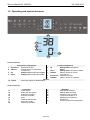
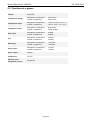
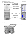
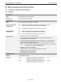
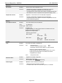
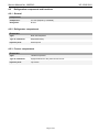
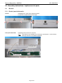
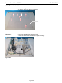
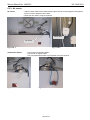
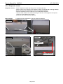
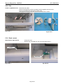
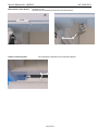
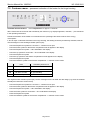
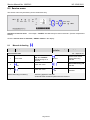
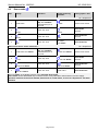
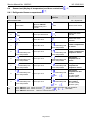
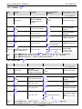
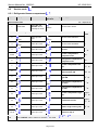
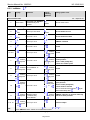
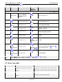
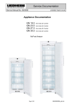
Service Documentation After Sales Service International Service Manual No. 199/2012 LWL/KDT-baj/08.08.12 Appliance Documentation HC 1540/1541 (ECN 5026 vers. 137/237 from Index 10) NoFrost fridge-freezer 30“ wide (freezer compartment with pull-out drawer) Page 1/43 199201200SM_gb Service Manual No. 199/2012 HC 1540/1541 Contents 1.0 2.0 3.0 3.1 3.2 4.0 4.1 Operating and control elements ............................................................................................. 3 Functions at a glance .............................................................................................................. 4 Description of appliance ......................................................................................................... 5 Sensor positions, schematic diagrams ...................................................................................... 6 Plinth layout ............................................................................................................................... 6 Main components and their functions ................................................................................... 7 Electrical components and functions ......................................................................................... 7 4.1.1 General .................................................................................................................................................. 7 4.1.2 Refrigerator compartment ..................................................................................................................... 8 4.1.3 Freezer compartment ............................................................................................................................ 9 4.2 Refrigeration components and functions ................................................................................. 11 4.2.1 General ................................................................................................................................................ 11 4.2.2 Refrigerator compartment ................................................................................................................... 11 4.2.3 Freezer compartment .......................................................................................................................... 11 5.0 Assembly instructions / replacement of parts .................................................................... 12 5.1 General ................................................................................................................................... 12 5.1.1 Control panel electronics ..................................................................................................................... 12 5.1.2 Power electronics ................................................................................................................................ 13 5.1.3 Condenser fan ..................................................................................................................................... 15 5.2 Refrigerator compartment........................................................................................................ 17 5.2.1 5.2.2 5.2.3 5.2.4 Door replacement .............................................................................................................................. 17 Hinge replacement ............................................................................................................................. 19 Soft-close mechanism replacement .................................................................................................... 21 Heating of hinge housing ..................................................................................................................... 21 5.3 Freezer compartment .............................................................................................................. 27 5.3.1 5.3.2 5.3.3 5.3.4 5.3.5 5.3.6 6.0 6.1 6.2 6.3 7.0 8.0 8.1 8.2 8.3 8.4 Dismantling the freezer compartment drawers ................................................................................... 27 Evaporator cover ................................................................................................................................. 29 Air sensor ............................................................................................................................................ 30 Evaporator sensor ............................................................................................................................... 31 Fan ...................................................................................................................................................... 32 Reed contact ....................................................................................................................................... 32 Technical data ....................................................................................................................... 34 General ................................................................................................................................... 34 Refrigerator compartment........................................................................................................ 34 Freezer compartment .............................................................................................................. 34 Customer menu – permanent activation of the heater for the hinge housing .................. 35 Service menu ......................................................................................................................... 36 Manual defrosting .................................................................................................................... 36 Demo mode ............................................................................................................................. 37 Panel test ................................................................................................................................ 38 Sensor test (display of temperature) and door contact test...................................................... 39 8.4.1 Refrigerator/freezer compartment ....................................................................................................... 39 8.4.2 IceMaker.............................................................................................................................................. 40 8.5 Service mode .......................................................................................................................... 41 8.5.1 Refrigerator/freezer compartment ....................................................................................................... 41 8.5.2 IceMaker.............................................................................................................................................. 42 8.5.3 Water tank pump 9.0 ......................................................................................................................... 43 Error code table ..................................................................................................................... 43 Page 2/43 Service Manual No. 199/2012 HC 1540/1541 1.0 Operating and control elements 10 1 2 3 4 11 15 12 16 13 17 14 18 5 6 7 8 9 23 19 20 21 °F°F 22 24 Control elements: 1 2 3 4 10 Refrigerator compartment SuperCool SuperCool function ON/OFF ON/OFF button for refrigerator compartment Up Setting button temperature higher Down Setting button temperature lower Alarm 5 6 7 8 9 General Alarm OFF button for audible alarm Freezer compartment Setting button temperature higher Down Setting button temperature lower ON/OFF ON/OFF button for freezer compartment SuperFrost SuperFrost function IceMaker ON/OFF button for IceMaker Up Control elements: 11 12 13 14 15 16 17 18 Front panel Power failure Clean dust filter (plinth) SuperCool activated Child lock activated Alarm IceMaker switched ON Water tank empty SuperFrost activated 19 20 21 22 23 24 Page 3/43 MagicEye Demo Mode activated Sabbath Mode activated Customer menu activated Temperature display in °F Refrigerator compartment temperature Freezer compartment temperature Service Manual No. 199/2012 HC 1540/1541 2.0 Functions at a glance Control: Electronics Temperature display: Refrigerator compartment: Freezer compartment: Actual value Actual value Temperature range: Refrigerator compartment: Freezer compartment: +36°F to +45°F (+2°C to +7°C) +6°F to -15°F (-14°C to -26°C) Temperature alarm: Refrigerator compartment: Freezer compartment: Not present Visual, audible Door alarm: Refrigerator compartment: Freezer compartment: Audible Audible Fan: Refrigerator compartment: Freezer compartment: Present Present Defrosting: Refrigerator compartment: Freezer compartment: Automatic Automatic Interior light: Refrigerator compartment: Freezer compartment: Present Present Service menu: Present Compressor: 2x VCC Solenoid valve refrigeration circuit: Not present Page 4/43 Service Manual No. 199/2012 HC 1540/1541 3.0 Description of appliance The HC 1540/1541 is a fridge-freezer with a NoFrost freezer compartment with IceMaker. The refrigerator compartment is cooled via a freely suspended rear wall evaporator. The temperature is controlled by an air sensor and an evaporator sensor. The temperature in the freezer compartment is controlled by an air sensor. The defrosting phases are initiated by way of the electronic control system, taking compressor running time and door openings into account. The appliance has 2 speed-controlled compressors. The refrigerator compartment and freezer compartment thus have separate refrigeration circuits and can be controlled separately. Page 5/43 Service Manual No. 199/2012 3.1 HC 1540/1541 Sensor positions, schematic diagrams Power PCB Front panel with PCB and reed contact Refrigerator compartment air sensor Refrigerator compartment evaporator sensor Freezer compartment air sensor Freezer compartment evaporator sensor Condenser 3.2 Plinth layout Refrigerator compartment compressor Condenser fan Filter Page 6/43 Freezer compartment compressor Service Manual No. 199/2012 HC 1540/1541 4.0 Main components and their functions 4.1 Electrical components and functions 4.1.1 General Electronics Type: Series 6 electronic control system Components: Control panel and power PCB Compressor Type: 2 VCC compressors (frequency-controlled) Function-refrigerator compartment: ON: Refrigerator compartment evaporator sensor switch-on value. Note: On-delay time (8 minutes) must have elapsed. OFF: Refrigerator compartment air sensor switch-off value ON: Freezer compartment air sensor switch-on value Note: On-delay time (8 minutes) must have elapsed. OFF: Freezer compartment air sensor switch-off value Function-freezer compartment: Function VCC: • Compressor with various speed settings. • The compressor is triggered via an inverter, the inverter electronics are mounted directly on the compressor. • The speed settings and switching-off of the compressor are controlled by the inverter via an appropriate frequency signal (pulse-width modulated square wave voltage on a separate signal line). Note: In the event of the frequency signal being interrupted, the compressor continues to run at a pre-specified speed! • Runtime longer than 70 minutes: Speed increase by one step during compressor operation. • Runtime shorter than 40 minutes: Speed reduction on next start-up. Condenser fan Position: In the appliance plinth Function: ON: - refrigerator compartment compressor on - freezer compartment compressor on. or OFF: - refrigerator compartment compressor off - freezer compartment compressor off and Page 7/43 Service Manual No. 199/2012 HC 1540/1541 4.1.2 Refrigerator compartment Electronics Setting range: Refrigerator compartment: +36°F to +45°F (+2°C to +7°C) Display range: +32°F to 99°F (actual value display) Temperatures colder or equal to 32°F are displayed as 32°F. Functions SuperCool: ON: refrigerator compartment is controlled at +36°F for 6 hours. OFF: The refrigerator compartment adjusts itself to the set value. Defrosting: Automatic during compressor standstill phase. Door alarm: When: If door is open, after 180 seconds. Audible: 3 beeps. Position: In sensor holder on the back of the evaporator. Function: - Switches the refrigerator compartment compressor ON. - Ends the defrosting phase. Position: In the refrigerator compartment on the right side wall. Function: - Switches the refrigerator compartment compressor OFF. - Generates the refrigerator compartment temperature display value. Position: In front panel. Type: Tube-type reed Sensors Evaporator sensor: Air sensor: Switch Door switch: Contact type: Make contact Function: Activation via: magnet on the door, magnet is replaceable. Switching signal when: Door closed: Fan Interior light ON OFF Door open: Fan Interior light Door alarm OFF ON ON after 180 seconds Loads Fan: Position: At the backside of the evaporator cover. Function: Parallel to the compressor. Note: Interior light: Heating for hinge housing: After switching off the compressor, the fan runs for 30 minutes. Position: In the air duct at the ceiling of the fridge compartment Function: - Shines as soon as the door is opened. - Is switched OFF after door has been open for 15 minutes. Position: Glued and foamed-in on the back of the two bottom hinge housings (left and right). Function: Can be activated when condensate collects. Page 8/43 Service Manual No. 199/2012 HC 1540/1541 4.1.3 Freezer compartment Electronics Setting range: +6°F to -15°F (-14°C to -26°C) Display range: +32°F to -58°F (actual value display) values over +32°F are indicated on bar display. Functions Temperature alarm: Alarm value: 4K warmer than set value. SuperFrost alarm value: +14°F (-10°C) Delay: 60 minutes Visual: Flashing temperature display. Audible: 4 beeps. During start-up: The temperature display flashes until the switch-off value is reached, the audible alarm is switched OFF. After the defrosting phase begins, the temperature alarm is suppressed for 1.5 hrs. Defrosting: ON: - During start-up after 6 hours cumulative compressor running time. - After a cumulative compressor running time of 15 to 24 hours maximum, depending on the number/duration of the door openings. As the defrosting phase begins, the compressor and fan are switched OFF and the defrost heater is switched ON. Duration: The defrost heater remains switched ON until such time as - the freezer compartment evaporator sensor has reached +41°F(+5°C) or - a max. defrosting time of 50 minutes has been reached. Door alarm: SuperFrost: Info: - After the end of the heating phase, the compressor is switched ON with a 10-minute delay. - If the SuperFrost function is activated during the defrosting phase, this will not interrupt defrosting. When: If door is open, after 180 seconds. Audible: 3 beeps. SuperFrost ON: Freezer compartment sets itself to -29°F (-34°C) for 30 hours. In the following 35 hours SuperFrost is ended automatically after the temperature falls 8K below the set value (at 0°F -> 8°F) or on expiry of the total period of 65 hours. SuperFrost OFF: The freezer compartment sets itself to the set value. Attention: If SuperFrost is actuated during a defrosting phase, the SuperFrost function is not performed before the defrosting phase has finished its cycle.. Page 9/43 Service Manual No. 199/2012 HC 1540/1541 Sensors Air sensor: Evaporator sensor: Position: On the front of the evaporator cover Function: - Switches the freezer compartment compressor on and off. - Freezer compartment evaporator sensor and freezer Compartment air sensor switch the freezer compartment fan ON. - Generates the freezer compartment temperature display value. Position: Slipped in, in the lower area of the lamellar evaporator. Function: - Freezer compartment evaporator sensor and freezer compartment air sensor switch the freezer compartment fan ON. - Ends the defrosting phase. Position: In the bar between the two drawers. Type: 2x reed PCB Switch Door/Drawer switch: Contact type: Make contact Function: Activation via: magnet foamed in on the top door interior on bottom left or the bottom door interior on top left. Magnet is not replaceable. Switching signal when: Door closed: Fan Interior light ON OFF Door open: Fan Interior light Door alarm OFF ON ON after 180 seconds Loads Fan: Position: Top centre of freezer compartment. Function: ON: - Compressor on and - Freezer compartment door closed and - Evaporator and air sensor switch-on value reached. Switch-on value evaporator sensor: a) During start-up / after defrosting phase: 0°F (-18°C). b) During normal operation 2K colder than freezer compartment air sensor. OFF: Defrost heater: Interior light: - Compressor OFF Position: Clipped into lamellar evaporator. Function: Defrosts the evaporator. For activation, see: Functions Defrosting Position: Below the cross connector and the bar. Function: - Shines as soon as the door is opened. - Is switched OFF after door has been open for 15 minutes. Page 10/43 Service Manual No. 199/2012 4.2 HC 1540/1541 Refrigeration components and functions 4.2.1 General Compressor Compressor: 2 x VCC (frequency-controlled) Refrigerant: R134a 4.2.2 Refrigerator compartment Evaporator Type: Rear wall evaporator Type of installation: Suspended freely. Injection point: At the top left 4.2.3 Freezer compartment Evaporator Type: Lamellar evaporator Type of installation: Upright between air duct panel and inner liner. Injection point: Top centre Page 11/43 Service Manual No. 199/2012 HC 1540/1541 5.0 Assembly instructions / replacement of parts 5.1 General 5.1.1 Control panel electronics Covers: - Disengage the covers at the marked locations. - Unclip the front panel at the left and right. Fig. 5.1.1/ 1 Fig. 5.1.1/ 2 Front panel with PCB: - Disengage and remove bus connector. Note: Front panel is only available in its entirety as a spare part, i.e. the PCB and tube-type reed are not available separately! Tube-type reed Bus connector Fig. 5.1.1/ 3 Page 12/43 Service Manual No. 199/2012 HC 1540/1541 5.1.2 Power electronics Cover: - remove fastening screw. - lift up cover at the rear and pull backwards. Cover Fig. 5.1.2/ 1 PCB carrier: - Disconnect all cables from the power PCB. - remove the entire PCB carrier from the appliance ceiling. Fig. 5.1.2/ 2 Page 13/43 Service Manual No. 199/2012 Power PCB: Fig. 5.1.2/ 3 HC 1540/1541 - Unclip and remove the cover of the PCB carrier. - Disengage the PCB at the marked locations. Fig. 5.1.2/ 4 Page 14/43 Service Manual No. 199/2012 HC 1540/1541 5.1.3 Condenser fan Fan mount: - Remove the ventilation grille and dust filter. - Press down the locating lugs of the mount at the same time and remove the mount from the funnel along with the motor. - Electrical connection is by means of a rigid plug-in connector. Left locating lug Right locating lug Fig. 5.1.3/ 1 Fig. 5.1.3/ 2 Plug-in connector Fig. 5.1.3/ 3 Page 15/43 Service Manual No. 199/2012 Fan mount: Fig. 5.1.3/ 4 HC 1540/1541 - unclip outer housing - strip the blades off the spindle. - remove fan motor from the mount. Please take care that the spring struts do not break! Fig. 5.1.3/ 5 Spring strut Spring strut Fig. 5.1.3/ 6 Fig. 5.1.3/ 7 Page 16/43 Service Manual No. 199/2012 5.2 HC 1540/1541 Refrigerator compartment 5.2.1 Door replacement CAUTION: To avoid injury to fingers or hands, both hinges must be loosened before replacing the door. Turn the screw in a clockwise direction (by approx. 8 turns) until it is in the 0-position. tightened loosened Fig. 5.2.1/ 1 Fig. 5.2.1/ 2 Page 17/43 Service Manual No. 199/2012 Disassembling the door HC 1540/1541 - Remove the fastening screws and take off the door. Note: When closed, the door is held to a certain extent by the effect of the magnet door seal. Support the door for safety or hold while removing the screws. - The hinges must be re-tightened as soon as the new door is mounted. Fig. 5.2.1/ 4 Fig. 5.2.1/ 3 Fig. 5.2.1/ 5 Adjust door: - Slightly loosen fastening screws. - With the help of the set screw on the respective mounting bracket the door can be adjusted in relation to the hinge and thus the appliance body. - Retighten the fastening screws afterwards. Set screw Set screw Fig. 5.2.1/ 6 Fig. 5.2.1/ 7 Set screw Set screw Fig. 5.2.1/ 8 Fig. 5.2.1/ 9 Page 18/43 Service Manual No. 199/2012 HC 1540/1541 5.2.2 Hinge replacement CAUTION: tensioned Fig. 5.2.2/ 1 To avoid injury to fingers or hands, both hinges must be loosened before replacing the door. Turn the screw in a clockwise direction (by approx. 8 turns) until it is in the 0-position. loosened Fig. 5.2.2 / 2 Page 19/43 Service Manual No. 199/2012 Hinge: HC 1540/1541 Remove fastening screws and hinge. On the outside, the hinge is hooked into the housing with two lugs. Recesses for lugs Fig. 5.2.2/ 4 Hinge Lugs Fig. 5.2.2/ 3 Hinge Fig. 5.2.2/ 5 Tighten hinge: To achieve the correct closing force, once the new hinge and door are mounted, the new hinge must be tightened. Note: Turn tensioning screw fully – not just until screw head is in I-position. Hinge Fig. 5.2.2/ 1 Hinge Fig. 5.2.2/ 6 loosened Fig. 5.2.2/ 7 tightened Fig. 5.2.2/ 8 Page 20/43 Service Manual No. 199/2012 HC 1540/1541 5.2.3 Soft-close mechanism replacement To prevent the door from slamming shut, two soft-close mechanisms are installed in each hinge housing. They are inserted in the recesses and can also be pulled out again. Soft-close mechanism Fig. 5.2.3/ 2 Soft-close mechanism Fig. 5.2.3/ 1 5.2.4 Heating of hinge housing To prevent condensation forming on the inside of the lower hinge housings, they are heated using a foamed-in heating system. Heating activation is described in chapter 7.0. Hinge housing Fig. 5.2.4/ 1 Page 21/43 Service Manual No. 199/2012 HC 1540/1541 5.2.5 Dismantling the refrigerator compartment evaporator cover Light cover: - Remove fastening screws and take off light cover. - Disconnect cable. Connector Fig. 5.2.5 / 1 Top air duct: - Remove fastening screws and withdraw air duct´. Top air duct Fig. 5.2.5 / 2 Bottom air duct: - Remove fastening screws and take off bottom cover. Fig. 5.2.5 / 3 Page 22/43 Service Manual No. 199/2012 Evaporator cover: HC 1540/1541 - Remove fastening screws, side retaining clips and bayonet screw. - Disconnect fan cable. - Pull forward bottom left corner of the cover slightly so that it slips out of the recess in the compartment liner in the area of the fan. - Then swivel forward the entire left side and remove the cover. Fan cable Fig. 5.2.5 / 4 5.2.6 Refrigerator compartment air sensor Air sensor: - Remove plugs and fastening screw from the sensor mount. - Pull out the air sensor through the back of the housing feedthrough and replace using the repair kit . Air sensor Fig. 5.2.6/ 1 Page 23/43 Service Manual No. 199/2012 HC 1540/1541 5.2.7 Refrigerator compartment evaporator sensor Evaporator sensor: - Loosen 4 bayonet screws. - Swing the evaporator to the left. Pull the sensor out of the mount. - Pull out the evaporator sensor through the back of the appliance feedthrough and replace using the repair kit. The repair instructions accompany the repair kit. Evaporator Fig. 5.2.7 / 2 Fig. 5.2.7/ 1 5.2.8 Refrigerator compartment fan Refrigerator compartment fan: - Unclip absorber ring along with fan. - Pull fan out of the absorber ring. Absorber ring Fig. 5.2.8/ 1 Fig. 5.2.8/ 2 Page 24/43 Service Manual No. 199/2012 HC 1540/1541 5.2.9 Water pump for IceMaker Base: - Remove fastening screws and twist up base. - Remove screws on the back. Fig. 5.2.9/ 1 Pump: Fig. 5.2.9/ 2 - Raise cover and disconnect water hose. Remove cover. - Disconnect cable for pump and reed contact. - Remove base and withdraw pump. Pump Hose Fig. 5.2.9/ 3 Fig. 5.2.9/ 4 Page 25/43 Service Manual No. 199/2012 HC 1540/1541 5.2.10 Pressure compensating valve Valve: - Pull out valve and remove lip. Valve Fig. 5.2.10 / 1 Page 26/43 Service Manual No. 199/2012 5.3 HC 1540/1541 Freezer compartment 5.3.1 Dismantling the freezer compartment drawers Remove insert: - Lift insert by approx. 2 cm at the front and then push back to unclip it at the rear. - Lift the insert up and out of the drawer. 2. 1. Fig. 5.3.1/ 1 Remove drawer: - Remove fastening screws on the left and right rails. - Unclip rails from the rear locking pins and remove the drawer. - Please note position of the adjusting aids at the front (important for assembly). Adjusting aid Fig. 5.3.1/ 2 Page 27/43 Service Manual No. 199/2012 Horizontal adjustment option: HC 1540/1541 - When assembling the drawers it must be ensured that the plastic shims under the front screws are properly mounted again. - They permit the horizontal adjustment of the drawers so that the outer edges are flush with the outer edges of the refrigerator compartment doors. - From the basic position (0) both drawers can be offset by 1mm or 2 mm respectively to the left or right. As an aid, the numbers and direction arrow are embossed on the shims Drawer offset to the left by 2mm: Neutral position: Drawer offset by 2mm to the right: Fig. 5.3.1/ 3 Fig. 5.3.1/ 4 Fig. 5.3.1/ 5 Page 28/43 Service Manual No. 199/2012 HC 1540/1541 5.3.2 Evaporator cover IceMaker: - Press up the locating lugs of the IceMaker and draw the IceMaker forwards. - Disconnect cables. Retaining Fig. 5.3.2/ 1 Cover: Fig. 5.3.2/ 2 - Unclip the air sensor and remove the four screws. - Draw the cover forwards and swing it out at the bottom. Cover Air sensor Fig. 5.3.2/ 3 Fig. 5.3.2/ 4 Page 29/43 Service Manual No. 199/2012 HC 1540/1541 5.3.3 Air sensor Air sensor: - Undo the strain relief for the cable feed-through at the back of the appliance and pull the sensor out of the appliance at the back. - Mount the new sensor using the repair kit. Strain relief Air sensor Fig. 5.3.3/ 1 Temperature limiter: Fig. 5.3.3/ 3 Fig. 5.3.3/ 2 - Unscrew the temperature limiter. - Cut into film to expose cable. - The new temperature limiter is put together using the repair kit. Fig. 5.3.3/ 4 Page 30/43 Service Manual No. 199/2012 HC 1540/1541 5.3.4 Evaporator sensor Evaporator sensor: - Raise evaporator module and swing it out in a forward direction. - Make incisions in the sheeting at the marked locations (see Fig. 5.3.4/ 1 and Fig. 5.3.4/ 2). - Bend or pull open the retaining lugs of the cover plate and remove it. - Draw the evaporator sensor to the left, out of the lamellar evaporator. - Undo the strain relief for the cable feed-through at the back of the appliance and pull the sensor out of the appliance at the back. - Mount the new sensor using the repair kit. Defrost heater: Is clipped into the evaporator fins. Can be replaced if defective. 1st step Fig. 5.3.4/ 1 Making an incision in the sheeting 2nd step 3rd step Defrost heater Evaporator sensor Fig. 5.3.4/ 2 Cutting open the evaporator cover Fig. 5.3.4/ 3 Lamellar evaporator Page 31/43 Service Manual No. 199/2012 HC 1540/1541 5.3.5 Fan Freezer compartment fan: - Disconnect fan cable. - Remove the fastening screws and detach the fan together with the mount. - Remove the blades and strip off the rubber rings. - Disengage the locating lugs and remove the bracket of the mount. Fig. 5.3.5/ 1 Fig. 5.3.5/ 2 5.3.6 Reed contact Reed PCB for upper drawer - Unclip the cover. - Remove the reed PCB from the mount and disconnect it. Cover Reed PCB Fig. 5.3.6/ 1 Fig. 5.3.6/ 2 Page 32/43 Service Manual No. 199/2012 Reed PCB for lower drawer HC 1540/1541 - Unclip the cover. - Remove the reed PCB from the mount and disconnect it. Cover Reed PCB Fig. 5.3.6/ 3 Position of the magnets: Fig. 5.3.6/ 4 - The magnets are foamed into the respective drawer. Magnet Fig. 5.3.6/ 5 Page 33/43 Service Manual No. 199/2012 HC 1540/1541 6.0 Technical data 6.1 General Sensor values: 6.2 Temperature [°C] Resistance value [kOhm] +35 +30 +25 +20 +15 +10 +5 0 -5 -10 -15 -20 -25 -30 -35 3.1 3.8 4.7 5.9 7.4 9.4 11.9 15.4 19.9 26.0 34.3 45.7 61.4 83.4 114.5 Refrigerator compartment Interior light Wattage: Voltage: 2 x 2,86 watts approx.. 13 Voltlt/DC Fan: Wattage: Voltage: 1,1 watts 11 Volt/DC Heating for hinge housing: Wattage: Voltage: 2x approx. 6 watts 115 Volt/AC 6.3 Freezer compartment Interior light 2 strips with 2 LEDs each: Wattage: 4 x approx. 1.1 W Voltage: approx. 18-20 V/DC, with connected LED lighting. In total: 4.4 W Fan: Wattage: Voltage: approx. 4,5 W 115 Volt/AC Defrost heater: Wattage: Voltage: approx. 194 W 115 Volt/AC Temperature fuse: Tripping temperature: +84°C (is defective after it has been tripped and has to be replaced) Page 34/43 Service Manual No. 199/2012 HC 1540/1541 7.0 Customer menu – permanent activation of the heater for the hinge housing Customer menu activation: Press "SuperFrost" for approx. 5 seconds. All the functions that can be set and activated by the customer (e.g. display brightness, child lock,...) are described in the operating instructions. Permanent activation of the heater is not described in the operating instructions because of the energy consumption: if, due to major condensate formation in the hinge housing, the heating should be permanently activated, state HI must be assigned a new heating activation period (HH): - Press the SuperFrost symbol for 5 seconds -> customer menu open - Press the Down symbol for the freezer compartment until H appears in the display - Press the SuperFrost symbol -> H0 is indicated in the display - Press the Up symbol for 5 seconds -> HH is indicated in the display - Press the SuperFrost symbol - Press the Up symbol for the freezer compartment until HI appears in the display - Press the SuperFrost symbol - Press the ON/OFF symbol for the freezer compartment -> customer menu closed New Activation period for HI HO Permanently OFF HA 20" ON / 40" OFF HI 20" ON / 40" OFF HL (as standard) Permanently ON HH The original heater activation period (HL) can be re-assigned to the HI state at a later stage (e.g. when the ambient humidity has returned to a lower level): - Press the SuperFrost symbol for 5 seconds -> customer menu open - Press the Down symbol for the freezer compartment until H appears in the display - Press the SuperFrost symbol -> H0 is indicated in the display - Press the Down symbol for 5 seconds -> HL is indicated in the display - Press the SuperFrost symbol - Press the ON/OFF symbol for the freezer compartment -> customer menu closed Page 35/43 Service Manual No. 199/2012 HC 1540/1541 8.0 Service menu The service menu may be used by service technicians only. Activation of service menu: buttons) Press "Up" + "ON/OFF" simultaneously for about 5 seconds (freezer compartment Once the service menu is activated, "MENU" flashes in the display. 8.1 Manual defrosting Step Display Operation Display following operation Testing option / Info Service menu start 1 Actual value 2 SF = SuperFrost Press "Up" and "ON/OFF" simultaneously for 5 seconds flashes static Manual defrosting ON selected static Manual defrosting ON activated Press "SF" once flashes 3 Press "SF" once static Manual defrosting is ended by: Service menu active, Manual defrosting selected - Switching appliance OFF/ON - Automatic after the defrost parameters are reached Page 36/43 Service Manual No. 199/2012 8.2 HC 1540/1541 Demo mode Step Display Operation Display following operation SF = SuperFrost Start service menu -- Demo mode ON -1 Actual value 2 Press "Up" and "ON/OFF" simultaneously for 5 seconds flashes Service menu active flashes Demo mode selected static Demo mode ON selected Press "Up" once flashes 3 Press "SF" once flashes 4 Press "SF" once static Set value and "Demo" Actual value and "Demo" 2 Press "Up" and "ON/OFF" simultaneously for 5 seconds flashes and "Demo" Service menu active flashes and "Demo" Demo mode selected static and "Demo" Demo mode OFF selected Actual value Demo mode OFF Press "Up" once flashes 3 Press "SF" once flashes and "Demo" 4 Demo mode ON SF = SuperFrost Start service menu --Demo mode OFF-1 Testing option / Info Press "SF" once static and "Demo" The text "Demo" in the display informs of the activated demo mode. Demo mode can be deactivated only via service menu, not by OFF/ON or disconnection from the supply. Operation switches to the mode wanted, demo mode or normal mode, as soon as "SuperFrost" has been actuated. Page 37/43 Service Manual No. 199/2012 8.3 HC 1540/1541 Panel test Step Display Operation Display following operation Service menu start 1 Actual value Testing option / Info SF = SuperFrost Press "Up" and "ON/OFF" simultaneously for 5 seconds flashes Service menu active Panel test -- test of sensor buttons, display elements, door sensor and beep -2 Press "Up" twice flashes 3 Panel test selected flashes static Panel test activated All symbols/segments All symbols/segments Press "SF" once flashes 4 Press "SF" once static 5 End All symbols/segments Doors closed/open and - Beep for 2 sec. press all buttons one after - appliance switches the other OFF (each operation is confirmed by a beep) After the last button has been pressed a beep sounds for 2 seconds, only if the test has been successful. Panel test cannot be ended in step 2, for example, it has to be performed in full. Should a button/sensor be defective, there will be no 2-second beep and the appliance will not switch OFF. The appliance then has to be unplugged and plugged back in again. Page 38/43 Service Manual No. 199/2012 8.4 HC 1540/1541 Sensor test (display of temperature) and door contact test 8.4.1 Refrigerator/freezer compartment Step Display Operation Display following operation Testing option / Info Service menu start 1 Actual value SF = SuperFrost Press "Up" and "ON/OFF" simultaneously for 5 seconds flashes Service menu active Sensor test and door contact test (sensor values without offset, appliance in control mode) 2 3 Sensor test mode selected static Sensor test mode activated Press "SF" once flashes 4 static Press "SF" once flashes alternately with sensor temperature 5 flashes alternately with sensor temperature Press "Up" once flashes alternately with sensor temperature flashes alternately with sensor temperature Press "Up" once flashes alternately with sensor temperature Press "Up" once 6 7 8 9 End flashes Press "Up" three times flashes flashes alternately with sensor temperature flashes alternately with sensor temperature Press "Up" once Press "Up" once Freezer compartment air sensor Freezer compartment evaporator sensor flashes alternately with sensor temperature Refrigerator compartment air sensor flashes alternately with sensor temperature Refrigerator compartment evaporator sensor flashes alternately with k or flashes alternately with k or Refrigerator compartment door contact (cL=door closed, oP=door open) Freezer compartment door contact (cL=door closed, oP=door open) Press "ON/OFF" once: Return to level 2 . No further points selectable with this appliance. Press "ON/OFF" twice: Return to level 1 . Points: , , , selectable Press "ON/OFF" three times: Return to normal/control mode Page 39/43 Service Manual No. 199/2012 HC 1540/1541 8.4.2 IceMaker Step Display Operation Display following operation Testing option / Info Service menu start 1 SF = SuperFrost Press "Up" and "ON/OFF" simultaneously for 5 seconds Actual value Service menu active flashes Sensor test and door contact test (sensor values without offset, appliance in control mode) 2 3 4 static Sensor test mode activated Press "Up" once static 56 Sensor test mode selected Press "SF" once flashes 65 flashes Press "Up" three times flashes IceMaker selected static Press "SF" once static flashes alternately with sensor temperature flashes alternately with sensor temperature Press "Up" once flashes alternately with k or IceMaker air sensor Ice-cube drawer door contact (oP=door open, cL=door closed) Press "ON/OFF" once: Return to level 2 . No further points selectable with this appliance. Press "ON/OFF" twice: Return to level 1 . Points: , , , selectable Press "ON/OFF" three times: Return to normal/control mode End 8.4.3 Water tank Step Display Operation Display following operation Testing option / Info Service menu start 1 Actual value SF = SuperFrost Hold down "Up" and "On/Off" together for 5 seconds flashes Service menu active Sensor test and door contact test (sensor values without offset, appliance in control mode) 2 flashes 3 static Sensor test mode activated Press "SF" once flashes 4 Press "Up" twice static 5 flashes Sensor test mode selected Press "Up" three times static Press "SF" once flashes alternately between k End Water tank selected static or Reed contact-water level (oP=empty, cL=full) Press "On/Off" once: Return to level 2 . No further items selectable with this appliance. Press "On/Off" twice: Return to level 1 . Points: , , , selectable Press "On/Off" three times: Return to normal/control mode Page 40/43 Service Manual No. 199/2012 8.5 HC 1540/1541 Service mode 8.5.1 Refrigerator/freezer compartment Step Display Operation Display following Testing option / Info operation Service menu start 1 Actual value SF = SuperFrost Press "Up" and "ON/OFF" simulflashes taneously for 5 sec. Service menu active Service mode -- testing electric loads-- 2 flashes 3 Press "Up" four times 4 Service mode activated --- All OFF approx. 4 W n/a static Freezer compartment compressor ON n/a static Refrigerator compartment compressor ON static Freezer compartment fan ON approx. 4.5 W static Freezer compartment defrost heater ON approx. 194 W static Refrigerator compartment light ON approx. 19 W static Refrigerator compartment fan slow approx. 6 W static Refrigerator compartment fan fast approx. 7 W Freezer compartment light ON approx. 8.5 W Condenser fan ON approx. 4.5 W Heater hinge housing ON approx. 12 W Return to step 5 --- Press "SF" once 155 static Press "Up" once static 6 Press "Up" once static 7 Press "Up" once static 8 Press "Up" once static 9 Press "Up" once static 10 Press "Up" once static 11 Press "Up" once static static 13 Press "Up" once static Press "Up" once static 14 Press "Up" once static End --- static static 5 15 Service mode selected flashes Press "SF" once flashes 12 Power input static Press "Up" once static static static Press "ON/OFF" once: Return to level 2 . Points: Press "ON/OFF" twice: Return to normal/control mode Page 41/43 , , , selectable Service Manual No. 199/2012 HC 1540/1541 8.5.2 IceMaker Step Display Operation Display following operation Testing option / Info Service menu start 1 Actual value SF = SuperFrost Press "Up" and "ON/OFF" simultaneously for 5 flashes seconds Service menu active Service mode -- testing electric loads-2 Press "Up" four times flashes 3 flashes Press "SF" once flashes 4 static Press "Up" once static 5 static Press "SF" once static 12 6 7 static static Press "Up" once flashes alternately with Press "SF" once Service mode selected Service mode activated IceMaker selected All OFF flashes All OFF alternately with - ice cube tray emptied and returns to flashes home position alternately with - 3 sec. water pump ON*) Drawer can remain open! 8 flashes Press IceMaker 1x alternately with "On/Off" flashes All OFF alternately with 9 flashes Press "Up" once alternately with flashes All OFF alternately with flashes alternately with - ice cube tray emptied and remains in flashes eject position alternately with - 25 sec. water pump ON*) Drawer must be closed! 10 Press "SF" once After 25 seconds have elapsed, flashes alternately with again 11 - Press IceMaker flashes ON/OFF button alternately with ( switch ON) - Close drawer flashes IceMaker switches on and ice cube tray alternately with returns to home position 6 12 flashes Press "Up" once alternately with static End Press "ON/OFF" once: Return to level 2: Items: , Press "ON/OFF" twice: Return to normal/control mode ) * Water pump only runs when the water tank is filling up. Page 42/43 Return to step 6 , selectable Service Manual No. 199/2012 HC 1540/1541 8.5.3 Water tank pump Step Display Operation Display following operation Testing option / Info Service menu start 1 SF = SuperFrost Actual value Press "Up" and "ON/OFF" simultaneously for 5 seconds Service menu active flashes Service mode -- testing electric loads-2 Press "Up" four times flashes 3 Service mode selected flashes Press "SF" once flashes 4 Service mode activated static Press "Up" once static IceMaker selected static Press "Up" once 5 static 6 Water tank pump selected static Press "SF" once All OFF Press "Up" once flashes All OFF alternately with static 97 static -Water tank pump ON for 10 seconds 8 flashes Press "SF" once alternately with flashes After the 10 seconds have elapsed, alternately with flashes alternately with 79 flashes Press "Up" once alternately with static End Return to step 7 Press "ON/OFF" once: Return to level 2 : Items: Press "ON/OFF" twice: Return to normal/control mode , , selectable 9.0 Error code table Error code Defective component Emergency mode F1 Refrigerator compartment air sensor Compressor 10 minutes ON and 30 minutes OFF. F2 Refrigerator compartment evaporator sensor Compressor 10 minutes ON and 30 minutes OFF. F3 Freezer compartment air sensor Compressor continuous operation F4 Freezer compartment evaporator sensor Compressor continuous operation FE IceMaker sensor Page 43/43