1
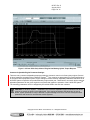
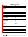
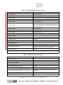
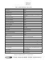
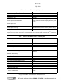
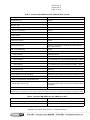
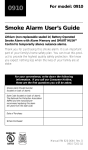
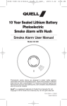
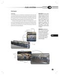
Revisions to this document are noted by a stripe in the lefthand margin SUBJECT: #1707, Rev. C August, 2013 Page 1 of 12 Troubleshooting Techniques for Low Power Complaints with Cummins ISB/ISL Engine MODELS AFFECTED: Allison H 40/50 EP SystemTM Introduction: The purpose of this bulletin is to provide the Servicing Technician with additional information and troubleshooting techniques in diagnosing engine low power complaints in conjunction with Diagnostic Trouble Codes (DTCs) in the Main Code 17 & 65 category. Table 1 contains the Diagnostic Trouble Codes most often associated with a low power complaint in the H 40/50 EP SystemTM. Table 1. Diagnostic Trouble Codes Associated With Engine Performance Description DTC Failure Record PBSS Display Lamp 1722 Engine Speed Profile Mismatch No Yes 6512 Engine Controller Stop Yes No Stop Engine Lamp 6513 Engine Controller Warning No No Check Engine Lamp 6514 Engine Controller Malfunction Indicator Lamp No No 6515 Engine Controller Protect Yes No Flash Stop Engine Light 6516 Engine Protection System Shutdown Yes Yes Stop System (Stop Engine Lamp) Disable Propulsion 6517 Engine Controller Idle Shutdown No Yes Flash Stop System 6523 Engine Torque Verification Yes Yes Stop System 6524 Engine Torque Verification at Neutral Yes Yes Check System 6525 Engine Failed to Crank No No 6526 Engine Performance Yes Yes WBD / SL5581EN 69323 Copyright © 2013 Allison Transmission, Inc. All Rights Reserved. #1707, Rev. C August, 2013 Page 2 of 12 Diagnostic Trouble Code (DTC) Descriptions: DTC 1722 Engine Speed Profile Mismatch Description: This DTC will be logged when a deviation (greater than 200 rpm) is detected between the Requested Engine Speed and Actual Engine Speed. Service: Retrieve the engine Fault Code(s) and refer to the Fault Code troubleshooting tree(s) in the appropriate Cummins Troubleshooting and Repair manual. NOTE: The H 40/50 EP SystemTM overspeed faults (codes with a main code of 81) may be logged in conjunction with this code. DTC 6512 Engine Controller Stop Description: This DTC is logged when the engine has or will shutdown. The engine sends an Engine Controller Stop message to the hybrid system indicating that it has detected a fault associated with the engine and will illuminate the stop engine lamp. Typically, the engine will shutdown to protect hardware from extreme conditions, i.e. engine overheat or low oil pressure. Service: The Engine Control Module (ECM) will have stored a Fault Code associated with this condition. Retrieve the engine Fault Code(s) and refer to the Fault Code troubleshooting tree(s) in the appropriate Cummins Troubleshooting and Repair manual. NOTE: The H 40/50 EP SystemTM does not shutdown the engine or illuminate any dash lamps during this diagnostic condition. DTC 6513 Engine Controller Warning Description: This DTC is logged when the engine sends an Engine Controller Warning message to the hybrid system indicating that it has detected a fault associated with the engine and will illuminate the check engine lamp. Service: The engine ECM will have stored a Fault Code associated with this condition. Retrieve the engine Fault Code(s) and refer to the Fault Code troubleshooting tree(s) in the appropriate Cummins Troubleshooting and Repair manual. NOTE: The H 40/50 EP SystemTM does not shutdown the engine or illuminate any dash lamps during this diagnostic condition. DTC 6514 Engine Controller Malfunction Indicator Lamp Description: This DTC is logged when the engine sends a message to the hybrid system indicating that it has detected a fault associated with the engine and will illuminate the Malfunction Indicator Lamp (MIL). Service: Typically, the MIL is illuminated when a diagnostic condition exists associated with the emission control system of the engine. The engine ECM will have stored a Fault Code associated with this condition. Retrieve the engine Fault Code(s) and refer to the Fault Code troubleshooting tree(s) in the appropriate Cummins Troubleshooting and Repair manual. Copyright © 2013 Allison Transmission, Inc. All Rights Reserved. #1707, Rev. C August, 2013 Page 3 of 12 NOTE: The H 40/50 EP SystemTM does not shutdown the engine or illuminate any dash lamps during this diagnostic condition. DTC 6515 Engine Controller Protect Description: This DTC is logged when the engine sends an Engine Controller Protect message to the hybrid system indicating that it has detected a fault associated with the engine that may warrant an engine shutdown condition. Service: The engine ECM will have stored a Fault Code associated with this condition. Retrieve the engine Fault Code(s) and refer to the Fault Code troubleshooting tree(s) in the appropriate Cummins Troubleshooting and Repair manual. NOTE: The H 40/50 EP SystemTM does not shutdown the engine or illuminate any dash lamps during this diagnostic condition. DTC 6516 Engine Protection System Shutdown Description: This DTC is logged when the engine has detected a condition that warrants an engine shutdown (i.e. engine overheat or low engine oil pressure). Service: The engine ECM will have stored a Fault Code associated with this condition. Retrieve the engine Fault Code(s) and refer to the Fault Code troubleshooting tree(s) in the appropriate Cummins Troubleshooting and Repair manual. DTC 6517 Engine Controller Idle Shutdown Description: Engine controller idle shutdown is an adjustable engine parameter setting. The setting is customer programmable and designed to shutdown the engine while in neutral at idle after a specified period of time. Service: Engine controller idle shutdown must be disabled with the H 40/50 EP SystemTM (see Customer Adjustable Engine Parameter Settings). The Customer Adjustable Engine Parameters can be verified using the Cummins INSITE tool. DTC 6523 Engine Torque Verification Description: This DTC is logged when there is a large deviation (greater than 500 N∙m) between reported and estimated engine torque while in Forward or Reverse. Either the engine is not producing enough torque or the engine is producing too much torque. Service: There may not be an ECM code associated with this condition. Refer to the Engine Performance Troubleshooting Tree in the appropriate Cummins Service Manual. DTC 6524 Engine Torque Verification at Neutral Description: This DTC is logged when there is a large deviation (greater than 500 N∙m) between reported and estimated engine torque while in Neutral. This condition will inhibit Neutral to range shifts. Either the engine is not producing enough torque or the engine is producing too much torque. Service: There may not be an ECM code associated with this condition. Refer to the Engine Performance Troubleshooting Tree in the appropriate Cummins Service Manual. Copyright © 2013 Allison Transmission, Inc. All Rights Reserved. #1707, Rev. C August, 2013 Page 4 of 12 DTC 6525 Engine Failed to Crank Description: This DTC is logged if the engine is unable to increase its speed by 25 rpm above the engine cranking speed of 600 rpm (above 32°F transmission sump temperature) or 820 rpm (below 32°F transmission sump temperature), after 10 seconds of cranking. The maximum engine cranking duration is 30 seconds. Service: Refer to the Engine Performance Troubleshooting Tree in the appropriate Cummins Service Manual. Refer to Allison SIL 2EP07 and Troubleshooting Manual TS3715EN. DTC 6526 Engine Performance Description: This DTC code is logged when the engine is not producing the requested torque as measured by the H 40/50 EP SystemTM. The H 40/50 EP SystemTM will respond by reducing system performance (output torque) in proportion to the engine performance reduction. There are three conditions that will log this code: Condition 1: Engine has a problem that is diagnosable (e.g. High engine temperature, low oil pressure) and cannot produce the requested engine torque. Since this condition is diagnosable, the engine still reports the actual engine torque to the hybrid system. In most cases, the ECM will have logged a Fault Code. Retrieve the engine Fault Code(s) and refer to the Fault Code troubleshooting tree(s) in the appropriate Cummins Troubleshooting and Repair manual. Condition 2: The engine has a problem that is NOT diagnosable by the ECM (e.g. Low fuel pressure, sticking/damaged exhaust brake valve) and cannot produce the torque requested by the hybrid system. The ECM may not log a Fault Code under these conditions. Refer to the Engine Performance Troubleshooting Tree in the appropriate Cummins Service Manual. Condition 3: Engine has a problem that is NOT diagnosable (e.g. damaged injectors) and cannot produce the engine torque requested by the hybrid system. This condition is NOT diagnosable and the engine reports the incorrect engine torque to the hybrid system. There will not be an ECM code associated with this condition. Refer to the Engine Performance Troubleshooting Tree in the appropriate Cummins Service Manual. Condition 3 Note: This DTC is different from 6523: Engine Torque Verification diagnostic. The Engine Torque Verification fault logic is insensitive to minor and medium engine torque reduction problems and only detects when there is a major torque reduction/increase from the engine (greater than 500 N∙m). Allison DOC® for PC–Service Tool (H 40/50 EPTM) Troubleshooting Techniques: Allison DOC® for PC–Service Tool (H 40/50 EPTM) can be used to view Requested Engine and Actual Engine Output Torque and Speed. Using the Strip Chart function, the parameters can be plotted and reviewed to assist in diagnosing vehicle low power complaints. Recording a Snapshot with Allison DOC®: Connect the laptop and necessary communication hardware to the vehicle diagnostic port. 1. Launch Allison DOC® for PC–Service Tool (H 40/50 EPTM) by double clicking the icon on the desktop. 2. Connect to the vehicle and press F6 (Fire Trigger) to begin recording. 3. Operate the vehicle while in range until the code becomes active or the low power condition is experienced. 4. Press F7 (Stop Recording) and save the Snapshot for replay and analysis. Playback of a Snapshot with Allison DOC®: 1. Launch Allison DOC® for PC–Service Tool (H 40/50 EPTM) by double clicking the icon on the desktop. Copyright © 2013 Allison Transmission, Inc. All Rights Reserved. #1707, Rev. C August, 2013 Page 5 of 12 2. Select the Snapshot / Playback / Open Playback File feature on the top toolbar and open the Snapshot previously saved. 3. Select the Diagnostic button or press F3 and select Strip Chart. The Strip Chart Configuration screen will appear. 4. Scroll to the Engine Information category, and highlight the parameters desired (i.e. Requested Engine Torque, Actual Engine Torque). Select the Add button to add the desired parameters to the graph. 5. Once parameter selection is complete, select the OK button to plot the Strip Chart. 6. Monitor Actual Engine performance vs. Requested Engine performance. Under normal circumstances the Actual Engine Torque will meet the Requested Engine Torque with some initial lag due to turbo spool up. Figure 1 provides a representation for a typical Requested Engine Torque vs. Actual Engine Torque acceleration scenario. 7. When Actual Engine Torque does not meet the Requested Engine Torque, vehicle performance will be degraded and H 40/50 EPTM output torque will be reduced. Figure 2 provides a representation for a typical Requested Engine Torque vs. Actual Engine Torque acceleration scenario where the engine is not capable of providing the requested torque. Figure 1. Allison DOC® Strip Chart of Engine Meeting Hybrid Torque Request Copyright © 2013 Allison Transmission, Inc. All Rights Reserved. #1707, Rev. C August, 2013 Page 6 of 12 Figure 2. Allison DOC® Strip Chart of Engine Not Meeting Hybrid Torque Request Customer Adjustable Engine Parameter Settings: There are many customer adjustable parameters within the electronic control unit of heavyduty engines. Several of these impact the operation of the H 40/50 EP SystemTM. They must be set appropriately for optimal performance of the entire vehicle propulsion system. Engine settings for these customer adjustable parameters that affect the H 40/50 EP SystemTM operation are provided below by engine model year. These lists do not contain all the customer adjustable parameters for the given engine but only those that impact the operation of the H 40/50 EP SystemTM. The remaining parameters are to be assigned by the vehicle OEM or the enduser customer. CAUTION: For H 50 EP SystemTM installations, the Customer Adjustable Engine Parameters and Values must be set exactly as shown in the table below. If the engine parameters and values are not set as shown, system performance may be affected or system damage could occur. Do NOT modify the listed parameters and values for use with other vehicle systems. Copyright © 2013 Allison Transmission, Inc. All Rights Reserved. #1707, Rev. C August, 2013 Page 7 of 12 Table 2. Cummins ISB and ISL (2013) Accelerator Interlock Disable Adjustable Low Idle Speed Low Idle Speed 700 or 750 rpm (must be same as CSS selection) Low Idle Speed Adjustment Switch Disable Aftertreatment Aftertreatment Diesel Particulate Filter Diesel Particulate Filter Regeneration Permit Switch Enabled (for vehicles with HUSHTM mode; otherwise, no preference) Alternator Failure Warning Alternator Speedup Disable Clutch Pedal Position Switch Not Installed Cruise Control Disable Cruise Control and Engine Brake Interaction Disable Engine Brake Control Delay Time 0.0 Seconds Engine Brake Type Exhaust Brake OR Variable Geometry Turbo Minimum Vehicle Speed 0.0 mph Clutch Pedal Activation Disable Service Brake Activation Disable Fan Control Fan on With Engine Brake Disable Fast Idle Warmup Disable Gear Down Protection Disable Governor Type Governor Type Automotive Governor Type Switch Disable Idle Shutdown Disable (refer to 6.6) J1939 Controls J1939 Stop Broadcast Allowed Disable Powertrain Protection Disable PTO Disable Road Speed Governor Maximum Accelerator Vehicle Speed Set to 130 mph or maximum allowed Maximum Vehicle Speed Set to 130 mph or maximum allowed Switched Maximum Vehicle Speed Disable SAE J1939 Multiplexing Copyright © 2013 Allison Transmission, Inc. All Rights Reserved. #1707, Rev. C August, 2013 Page 8 of 12 Table 2. Cummins ISB and ISL (2013) (cont’d) Accelerator Pedal or Lever Position Enable Source Address 3 Transmission #1 Aftertreatment Regeneration Permit Switch Disable (Enable only for vehicles with HUSHTM Mode) 3 – Transmission #1 * (only for vehicles with HUSHTM Mode) Source Address Enable (only for vehicles with HUSHTM Mode) Auxiliary Shutdown Switch Source Address 3 Transmission #1 Enable for vehicles that are configured to "Use engine cooling fan for auxiliary braking" and/or have the transmission cooler stacked with the engine cooler (Vehicle Fan Configurations 1 & 2 on the CSS form) Fan Control Switch Source Address 3 Transmission #1 Idle Validation Switch Enable Source Address 3 Transmission #1 Switched Maximum Engine Operating Speed Disable Transmission Setup Top Gear Transmission Ratio 0.5 Transmission Type Automatic Vehicle Acceleration Management (VAM) Disable (ISB only; VAM does not apply to ISL) Vehicle Speed Source Number of Transmission Tailshaft Gear Teeth 16 Vehicle Speed Sensor Type Magnetic (only if wired on the vehicle. If not, set to "Data Link Tailshaft", which is Cummins’ preferred setting) Two Speed Rear Axle Disable * Trap regeneration controller will listen to only one source address. The transmission is an acceptable source address. If the vehicle controller is the source address, then the vehicle controller must listen to the transmission controller CAN message and respond accordingly. Table 3. Cummins ISB and ISL (2010) Accelerator Interlock Disable Accelerator Options Remote Accelerator Pedal or Lever Enable (only if a throttle is used with the rear start option) Adjustable Low Idle Speed Low Idle Speed 700 rpm Low Idle Speed Adjustment Switch Disable Aftertreatment Diesel Particulate Filter Regeneration Permit Switch Enable (for vehicles with HUSHTM mode; otherwise, no preference) Alternator Failure Warning Idle Speedup Disable Copyright © 2013 Allison Transmission, Inc. All Rights Reserved. #1707, Rev. C August, 2013 Page 9 of 12 Table 3. Cummins ISB and ISL (2010) (cont’d) Clutch Pedal Position Switch Not Installed Cruise Control Disable Cruise Control and Engine Brake Interaction Disable Engine Brake Control Enable Delay Time 0 sec Engine Brake Type Exhaust Brake (if Exhaust Brake can not be selected, use Undefined) Minimum Vehicle Speed 0 mph Clutch Pedal Activation Disable Service Brake Activation Disable Fan Control Fan on with engine braking Disable Fast Idle Warmup Disable Gear Down Protection Disable Governor Type Governor Type Automotive Governor Type Switch Disable Idle Shutdown Disable (refer to 2.9.6) J1939 Controls J1939 Stop Broadcast Allowed Disable Powertrain Protection Disable PTO Disable Road Speed Governor Disable (If locked Enabled, set Maximum Vehicle Speed to 130 mph or maximum allowed) SAE J1939 Multiplexing Accelerator Pedal or Lever Position Source Address 3 – Transmission #1 Aftertreatment Regeneration Permit Switch Source Address Auxiliary Shutdown Switch Enable Disable (Enable only for vehicles with HUSHTM Mode) 3 – Transmission #1 * (only for vehicles with HUSHTM Mode) Disable (Enable only for vehicles with HUSHTM Mode) Source Address 3 – Transmission #1 (only for vehicles with HUSHTM Mode) Fan Control Switch Enable (only for vehicles that enable "Use engine cooling fan for auxiliary braking" in the H 40/50 EP SystemTM cal, otherwise Disable) Source Address Idle Validation Switch Source Address 3 – Transmission #1 Enable 3 – Transmission #1 Copyright © 2013 Allison Transmission, Inc. All Rights Reserved. #1707, Rev. C August, 2013 Page 10 of 12 Table 3. Cummins ISB and ISL (2010) (cont’d) Switched Maximum Engine Operating Speed Disable Transmission Setup Top Gear Transmission Ratio 0.5 Transmission Type Automatic Vehicle Acceleration Management Disable (ISB only; VAM does not apply to ISL) Vehicle Speed Sensor AntiTampering Disable (if locked Enabled, set Tampering Sensitivity Level to Low) Vehicle Speed Source Number of Transmission Tailshaft Gear Teeth 16 Vehicle Speed Sensor Type Magnetic (only if wired on the vehicle. If not, set to DATALINK TAILSHAFT SPEED, which is Cummins’ preferred setting) Two Speed Rear Axle Disable * Trap regeneration controller will listen to only one source address. The transmission is an acceptable source address. If the vehicle controller is the source address, then the vehicle controller must listen to the transmission controller H 40/50 EP SystemTM message and respond accordingly. Table 4. Cummins ISB CM2150 and ISL CM2150 (2007) Accelerator Interlock Disable Accelerator Options Remote Accelerator Pedal or Lever Enable (only if there is a throttle used with a rear start option) Adjustable Low Idle Speed Low Idle Speed 600 rpm Low Idle Adjustment Switch Disable After Treatment Diesel Particulate Filter Regeneration Permit Switch Enable (for vehicles with HUSHTM mode; otherwise, no preference) Alternator Failure Warning Disable Idle Speedup Clutch Pedal Position Switch Not Installed Cruise Control Disable Cruise Control and Engine Brake Interaction Disable Engine Brake Control Enable Delay Time 0 sec Engine Brake Type Exhaust Brake Minimum Vehicle Speed 0 mph Clutch Peal Activation Disable Service Brake Activation Disable Fan Control Copyright © 2013 Allison Transmission, Inc. All Rights Reserved. #1707, Rev. C August, 2013 Page 11 of 12 Table 4. Cummins ISB CM2150 and ISL CM2150 (2007) (cont’d) Fan on with engine braking Disable Fast Idle Warmup Disable Gear Down Protection Disable Governor Type Governor Type Automotive Governor Type Switch Disable Idle Shutdown Disable (refer to 2.9.6) J1939 Controls J1939 Stop Broadcast Allowed Disable Powertrain Protection Disable PTO/Remote PTO Disable Road Speed Governor Disable (if locked Enabled, set Maximum Vehicle Speed to 130 or Max. Allowed) SAE J1939 Multiplexing Enable Accelerator Pedal or Lever Position Source Address Enable 3Transmission #1 After Treatment Regeneration Permit Switch Disable (Enable only for vehicles with HUSHTM Mode) 3 – Transmission #1 * (only for vehicles with HUSHTM Mode) Source Address Disable (Enable only for vehicles with HUSHTM Mode) Auxiliary Shutdown Switch 3 – Transmission #1 (only for vehicles with HUSHTM Mode) Source Address Transmission Setup Transmission Type Automatic Vehicle Acceleration Management Disable Vehicle Speed Sensor AntiTampering Disable (if Locked Enabled, set tampering sensitivity to low) Vehicle Speed Source Number of Transmission Tailshaft Gear Teeth 16 Vehicle Speed Sensor Type Magnetic (only if wired on the vehicle; if not, set to DATALINK TAILSHAFT SPEED which is the Cummins’ preferred setting regardless) Two Speed Axle Disable * Trap regeneration controller will listen to only one source address. The transmission is an acceptable source address. If the vehicle controller is the source address, then the vehicle controller must listen to the transmission controller CAN message and respond accordingly. Table 5. Cummins ISB CM850 and ISL CM850 (pre 2007) Accelerator Interlock Disable Adjustable Low Idle Speed Low Idle Speed 600 rpm Copyright © 2013 Allison Transmission, Inc. All Rights Reserved. #1707, Rev. C August, 2013 Page 12 of 12 Table 5. Cummins ISB CM850 and ISL CM850 (pre 2007) (cont’d) Low Idle Adjustment Switch Disable Battery Voltage Monitor Disable Idle Speedup Cruise Control Disable Engine Brake Control Enable Cruise Control Activation Disable Engine Brake Delay Time 0 sec Engine Brake Minimum Vehicle Speed 0 mph Engine Brake Type Exhaust Brake Service Brake Activation Disable Fast Idle Warmup Disable Gear Down Protection Disable Governor Type (was Accelerator Type) Accelerator Type Automotive Governor Type Switch Disable Disable Idle Shutdown J1939 Controls (was Generic Tool Permissions) J1939 Stop Broadcast Allowed Disable Powertrain Protection Disable PTO/Remote PTO Disable Remote Accelerator Enable (only if there is a remote throttle used with the rear start option) Remote Governor Disable (if locked Enabled, set Maximum Vehicle Speed to 130) SAE J1939 Multiplexing Enable (if controller supports J1939 multiplexing) Accelerator Pedal Position Idle Validation Switch Source Address 3Transmission #1 Transmission Setup Clutch Pedal Position Switch Not Installed Transmission Type Automatic Vehicle Acceleration Management Disable Vehicle Speed Source Two Speed Rear Axle Disable Vehicle Speed Sensor Type Magnetic (only if wired on the vehicle; if not, set to DATALINK TAILSHAFT SPEED which is the Cummins’ preferred setting regardless) Number of Transmission Tailshaft Gear Teeth 16 Copyright © 2013 Allison Transmission, Inc. All Rights Reserved.