1
Cash Register
ECR 7900
SERVICE MANUAL
Code Y108540-8
PUBLICATION ISSUED BY:
Olivetti S.p.A.
10015 Ivrea (Italy)
Gruppo Telecom Italia
Via Jervis, 77- 10015 Ivrea (ITALY)
www.olivetti.com
Copyright© 2008, Olivetti
All rights reserved
ATTENZIONE
Pericolo di esplosione se la batteria non viene sostituita in modo corretto.
Sostituire solo con un tipo uguale o equivalente raccomandato dal costruttore.
Eliminare le batterie usate seguendo le istruzioni del costruttore.
CONTENTS
MAJOR FEATURES................................................................................................... 1
ECR 7900 CASH REGISTER COMPONENTS .......................................................... 2
CASH REGISTER SPECIFICATIONS ....................................................................... 3
SAFETY PRECAUTIONS ........................................................................................................ 4
MAINTAINING THE CASH REGISTER ................................................................................... 4
UNPACKING AND SETTING UP THE CASH REGISTER......................................... 5
STANDARD ACCESSORIES .................................................................................................. 5
THE KEYPAD FOR ECR 7900................................................................................... 6
KEYPAD FUNCTIONS............................................................................................................. 6
OPERATOR AND CUSTOMER DISPLAYS ............................................................... 9
SWITCHING THE OPERATOR DISPLAY ON ......................................................................... 9
SWITCHING THE OPERATOR DISPLAY 0FF ........................................................................ 9
SYMBOLS AND MESSAGES.................................................................................................. 9
PROGRAMMING MODE – Operator Display ......................................................... 11
PRINTER COMPARTMENT..................................................................................... 12
1. PRODUCT OUTLINE ........................................................................................... 15
1-1. HARDWARE................................................................................................................... 15
1-2. DISPLAY......................................................................................................................... 15
1-3. KEYBOARD ................................................................................................................... 16
1-4. DRAWER ........................................................................................................................ 17
1-5. PRINTER ........................................................................................................................ 18
1-6. INTERFACE.................................................................................................................... 18
1-7 SYSTEM BLOCK DIAGRAM .......................................................................................... 19
2. TROUBLE SHOOTING GUIDANCE .................................................................... 19
2. TROUBLE SHOOTING GUIDANCE .................................................................... 20
3. CIRCUITRY .......................................................................................................... 21
3-1 POWER SUPPLY CIRCUIT ............................................................................................. 21
3-2. TRANSFORMER WIRING DIAGRAM............................................................................ 23
3-3. M30842MC
MICROCOMPUTER.................................................................................. 24
3-4. RESET CIRCUIT ............................................................................................................ 27
3-5. POWER FAIL CIRCUIT .................................................................................................. 28
3-6. WINDING MOTOR CIRCUIT .......................................................................................... 28
3-7. DISPLAY CIRCUIT ......................................................................................................... 30
Y108540-8
ECR 7900 Service Manual
I
3-8. DISPLAY INFORMATION............................................................................................... 32
3-9. KEYBOARD CIRCUIT .................................................................................................... 33
3-10. DRAWER CIRCUIT....................................................................................................... 34
3-11. BUZZER CIRCUIT ........................................................................................................ 35
3-12. BATTERY CIRCUIT ...................................................................................................... 36
3-13. EXTERNAL MEMORY.................................................................................................. 38
3-13-1. SRAM (BS62LV4006SCP-70)........................................................................... 38
3-13-2. FROM (S29AL004D70TFI010) ......................................................................... 40
3-14. PRINTER CIRCUIT....................................................................................................... 43
3-15. INTERFACE CIRCUIT .................................................................................................. 46
4. DIAGNOSTIC SOFTWARE.................................................................................. 48
4-1. DIAGNOSTIC CHECK & FINISHED GOODS CHECK................................................... 48
4-2. SOFTWARE VERSION CHECK ..................................................................................... 56
5. INSTALLING SOFTWARE ................................................................................... 58
5-1.USB driver install ........................................................................................................... 66
6. ASSEMBLY INSTRUCTION................................................................................. 73
6-1. TOP CASE UNIT ............................................................................................................ 73
6-2. Display unit ASSY ......................................................................................................... 80
6-3. Bottom case unit ASSY ................................................................................................ 83
8. CIRCUIT DIAGRAM ............................................................................................. 93
9. EXPLODED DIAGRAM...................................................................................... 101
II
ECR 7900 Service Manual
Y108540-8
PREFACE
This Service Manual is addressed to the field engineers who will install and service the cash
register. it also provides product maintenance guidelines.
SUMMARY
This manual Is divided into five chapters.
The first two chapters describe the operating, functional checks and maintenance
procedures.
Chapter 3 describes the disassembly and reassembly procedures, Chapter 4 gives
troubleshooting/repair
information while Chapter 5 describes the electronic circuitry.
PREREQUISITES
The topics described in this manual require knowledge of similar products.
REFERENCE DOCUMENTATION
• Instruction Manual (provided with the product)
• Spare Parts Catalogue
-
DISTRIBUTION: General
LAST EDITION: January 2008
Y108540-8
ECR 7900 Service Manual
III
MAJOR FEATURES
•
•
•
•
•
•
•
•
•
•
•
•
•
•
•
•
•
e
•
•
•
•
•
e
e
e
e
e
e
e
•
•
•
99 departments that can be grouped into up to 10 merchandise categories;
Up to 3,000 Price Look-Ups (PLU) with the possibility of associating a department and tax
status to each;
15 clerk numbers to monitor the sales of individual employees with programmable Clerk
security system;
Maximum 12,000-line internal Electronic Journal memory, substantially expandable via
SD card;
Thermal printer with journal record or receipt printing capabilities;
PLU creation for barcoded articles and barcode programming;
Cash register programming via computer;
Quantity entries using decimal point;
Training mode facility with related password;
Replaceable keycaps;
Receipt on/off capabilities;
Programmable names for departments, department (merchandise) groups, clerks, PLUs,
foreign currencies and payment media;
Customer sales receipt header and footer personalization and logo creation via PC;
Special rounding capabilities for Swiss, Danish and Swedish and Euro currencies;
Detailed department programming;
4 foreign currency exchange rates with reIated currency descriptors;
Cash, check, charge card and 6 other credit card tender media keys, with change
tendered on all payments; 4 different VAT rates, with temporary override;
Sales transaction hold and recall function;
Battery back-up protection for sales transaction and programming data;
Programmable clerk operating limitations for enhanced security;
Payment transfer from one payment media to another after transaction completion;
Single-line customer display with programmable scrolling messages;
LCD operator display with Menu system f or accessing all cash register functions;
Optional passwords for Manager mode, X report mode and Programming/Z report
modes;
PLU rapid inquiry key;
PLU fast programming key;
Programmable VAT details printing on sales receipts;
Multi-lingual interface f or customer receipts, management reports and display messages
in Danish, Dutch, English, French, German, Portuguese, Spanish and Swedish;
User-defined captions in any language for printing on receipts and reports;
Keypad personalization through reassignment of keys;
Programmable key sequences executed by actioning single chain function keys;
Sales function selection via pop-up Iists;
Barcode reader connectivity.
Y108540-8
ECR 7900 Service Manual
1
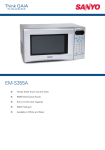
ECR 7900 CASH REGISTER COMPONENTS
With reference to figure:
1. Customer display.
2. Operator display.
3. Keypad.
4. Cash drawer and box.
5. Cash drawer lock and slot.
6. Item deposit drawer.
7. Power cord.
8. Storage Device (SD) - under printer compartment cover.
9. Printer compartment cover with receipt output window.
10. USB interface for connecting the computer for cash register programming. See
the note below.
11. RS232 serial interface for barcode reader.
NOTE:
From the company website you can download the software
needed to program the cash register directly from your computer.
2
ECR 7900 Service Manual
Y108540-8
CASH REGISTER SPECIFICATIONS
Technical Characteristics
Listed below are the technical characteristics of this cash register model.
Type:
Electronic cash register with clamshell thermal printer, 10 departrnent groups, 99
departrnents, 15 derks, up to 3,000 PLU settings. Max. 12,000-line Electronic
Journal internal memory, expandable via memory storage device. Removable cash
drawer.
Displays: 160x80 dot, tiltable, Operator LCD for displaying all transaction data with menu
system for cash register programming. 1 0-digit Client alphanumeric display.
Symbols for change, subtotal, minus, total, foreign currency value, department
number and item count shown.
Capacity: 8-digit input and readout
Printer:
24-column line thermal printer with drop-in paper loading.
Paper supply: 58.5 ± 0.5 mm thermal paper.
Batteries:
3 standard ‘ AA’ size batteries which safeguard
memory contents in the event of power failures.
Technology: CMOS RAM.
Powercons.
Standby 12.1 W, Operating4l.8W.
Operating 32 — 104°F (0°C —40 °C)
Temperature:
Dimensions: 10 mm (W) x 430 mm (D) x 294 mm (H)
Weight:
Y108540-8
9,9 Kg (21,82 lbs)
ECR 7900 Service Manual
3
SAFETY PRECAUTIONS
The power socket for this cash register must be Iocated near the machine and must be easily
accessible.
Do not use this cash register outdoors in the ram or near any Iiquid.
MAINTAINING THE CASH REGISTER
Provided below is information on how to maintain the cash register.
Note:
Before cleaning the cash register, make sure it Is powered off and/or unplugged from
the wall outlet. Before unplugging the cash register from the wall outlet, make sure
that three charged AA standard backup batteries are installed in the battery
compartment. All data stored in memory will be cancelled if you unplug the cash
register from the electrical wall outlet without back-up battery supply.
1.
Keep all liquids away from the cash register so as to avoid spills which could damage
the electronic components.
2.
To clean the cash register firstly turn it off and/or unplug it from the wall outlet (be sure
the back-up batteries are installed), then use just a damp cloth. Do not use corrosive
substances such as solvents, alcohol, petrol, or abrasive components.
3.
Il the cash register is stored in extreme hot or cold temperatures (0 °C – 40 °C), allow
the temperature inside the cash register to reach room temperature before turning it on.
4.
DO NOT attempt to pull the paper tape when the cash register Is printing or when you
are loading paper. Always use the [Feed] key to feed paper. Pulling the paper tape
could damage the print mechanism.
4
ECR 7900 Service Manual
Y108540-8
UNPACKING AND SETTING UP THE CASH REGISTER
STANDARD ACCESSORIES
The cash register comes with the following items:
•
One black plastic journal winder spindle
•
One roll of standard paper tape
•
Three standard ‘AN’ size batteries for the battery back-up system
• The multilingual User’s Guide, Reference Guide in English and Warranty Card + Setup
Poster
• A set of keys for looking the cash drawer
Make sure that the cash register and all of the above items are included in the shipping canon.
Open the cash register’s shipping carton and carefully withdraw each component. Make sure
that the cash register and all al its accessories, listed in the section entitled Standard
Accessories, are present in order to setup the cash register by following these guidelines:
1.
Place the cash register on a level, stable, vibration-free and dust-free surface. Make sure it
is near a power outlet compliant will the latest safety standards.
2.
Plug the cash register into a power outlet compliant with the latest safety standards.
3.
Insert memory backup batteries as explained in the section entitled Inserting/Replacing
Batteries. Do not insert the batteries unless the cash register is plugged into an electrical
power outlet.
WARNING: The machine must be plugged into an electrical outlet before you insert the
batteries.
4. Load the thermal paper roll as explained in the section entitled Loading Thermal Paper.
5. Set the desired program options as explained in the section Cash Register Programming.
Y108540-8
ECR 7900 Service Manual
5
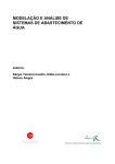
THE KEYPAD FOR ECR 7900
The figure below shows the keypad layout
22
3
4
6
5
24
1
19
23
21
2
7
8
20
18
9
10
17
11
16
15
14
13
12
KEYPAD FUNCTIONS
The keys described here are those configured by default on the cash register keyboard, shown
in figure 5. The symbol (*) indicates that the key is also used in caption programming.
NOTE:
Settings”, if
The keys can be reconfigured using the Free Key Layout option in “Advanced
required.
1. - Advances the receipt or journal paper one me feed; advances the paper
continuously when held down. Interrupts report printing when kept depressed.
2. - Pop-up list (2) allowing EC/VOID, FULI VOID or REFUND operations to be
performed. As EC/VOID, deletes the last item entered, and corrects a particular entry
after it is processed and printed. FULL VOID deletes full entries after a subtotal 1As REFUND,
subtracts an item that is returned for refund; sales and activity totals are also rectified.
3. - As [CLERK] confirms the clerk code entered. As the [ESC] key in programming
mode, displays the previous menu or exits caption programming.
4. -
Toggles the cash register between printing and not printing the sales receipt in
registration and manager modes.
5. -Allows price entries for departments 20-38 and 39-99. For departments 20-38,
press this key before pressing the corresponding department key. For departments
39-99, press this key, manually enter the department number using the numeric keypad and
then press this key again.
6. -(*) Holds and then recalls a sales transaction so that a second transaction can be
performed in the meantime. In caption programming, toggles between caps on/off to
allow captions to be written in upper or lower case letters.
6
ECR 7900 Service Manual
Y108540-8
7. - (*) Transfers payment from one form of payment media to another after the sales
transaction is finalized.
8. - -(*) Pop-up list (5) allowing FC or TAKE-OUT sales operations to be performed. As
FC, automatically calculates and displays the value in foreign currency of the subtotal of
a sale or of a particular amount registered. As the TAKE-OUT key modifies temporarily the tax
status associated with a PLU code.
9. -(*) Pop-up list (1) allowing transaction payment to be registered to a check, charge
card, or one of six credit cards.
10. -(*)Subtotals a sale
11. - As the [TOTAL]key totals exact cash transactions, computes change and
totals transactions that are split tendered with check, credit card and/or cash.
Pressed a
second time, prints one or more copies of the last receipt, depending on how multiple receipts
are programmed (see “Receipt Printing Mode”). As [ENTER], in Programming mode, selects a
menu option when it is highlighted, or confirms the data entered for a form field.
12. (*) Registers single or multiple item sales to departments numbered
between 1 and 38. To enter a department number from 1 to 19, press the
corresponding key. To enter a
department number from 20 to 38, press first the
key, then the corresponding
department key. For department numbers from 39 to 99, see
above.
In caption programming, these keys can be used to input the characters indicated on the
related key as indicated in the Character Table. You can define clerk names, receipt
header/footer, department names, department group names, PLU product names, currency
identifiers and credit card
captions. As the [SP] key,
can be used to add spaces between characters and to
confirm entry of repeated characters.
13. - (*) Enters a decimal point for defining product quantities with decimals during
sales transactions. In caption programming, as the [DEL] key, it performs the typical
backspace function for deleting the last character entered.
14. -(*) Input amounts, indicate multiple items, add and subtract
amounts and percentages, and input department numeric codes from
39 to 99
(see”
“above).
15. - When operated outside of a sales transaction, displays setup information: the
current date and time, clerk number, Electronic Journal status and number of free EJ
lines.
Using
and
the LCD contrast can be adjusted. When operated during a sales
transaction, allows multiple quantities to be specified for a sales item.
Y108540-8
ECR 7900 Service Manual
7
16. - (*) Clears an entry made from the numeric keypad or with
before finalizing a
transaction with a Department or function key. Also used to clear error conditions. In
caption programming, deletes any caption characters entered before pressing
In 0ff mode, activates menu for resetting cash register.
17. - Price look-up function. Registers the preset price of an individual item to the
appropriate department. When programming PLUS, to display a given PLU, enter its
number then press this key.
18. - (*) Temporarily overrides a price that was assigned to a PLU number. During
caption programming, when pressed before a character, sets the character as double
width.
19. - Pop-up list (4) allowing Paid Out (P0) or Received on Account (RA) transactions.
As the P0 key registers any money taken out of the cash drawer that is not part of a
sale.
AS the RA key registers any money received on account that is not part of a
sale, for example, the start-up money put in the drawer at the start of each business
day can be registered as RA.
20. - Pop-up list (3) allowing direct/percent discounts and add-on operations: as the 1%
+/- or 2% +/- key, when appropriately programmed, applies a preset percentage
reduction or add-on to the price of an item or to the sales total. As the 1+/- or 2 +/key, subtracts or adds an amount from/to an item or sales total.
21. - Opens the cash drawer without registering any amount or when changing cash for
a non-sales transaction. When programming entities such as clerks PLUs, depts and so
on, press
…... and so on).
to display the next item in numeric sequence (i.e.: clerk O1, clerkO2,
22. - When the operator display is off, this key switches it on. When the display is on,
pressing this key displays the Main menu. The Main menu contains the 0ff mode option
which you can use to switch the operator display off. During a clerk transaction, allows
you to switch to Manager mode to perform operations disabled for the clerk. Pressing
the key again afterwards, switches back to the clerk transaction.
23. - In Programming mode, these keys can be used to move through the menu
options and form fields in the direction indicated on the key.
When the menu item required is highlighted, press
to select it.
When navigating forms, if me numbers are present on the left, jump to the line
you want by entering its number followed by either arrow key.
24. - In Programming mode, when selecting data for preset value fields, use
these keys to scroll through the values available, highlight the value wanted,
and then select with
8
ECR 7900 Service Manual
Y108540-8
OPERATOR AND CUSTOMER DISPLAYS
The operator LCD display has a Menu system providing access to all cash register functions.
You can raise and tilt the display to obtain the most comfortable viewing position. The pop-up,
single-line, customer display can be raised and swivelled to obtain the most favorable
position for customer viewing. When sales transaction data is not displayed, scrolling
messages can be
programmed to appear according to the cash register state (idle, off and so on).
SWITCHING THE OPERATOR DISPLAY ON
To switch on the operator display press the
key on the keypad. The Main menu is
displayed from which you can select:
• Registration mode - to enter sales transactions as a clerk (also in training mode)
• Manager mode - to enter all sales transactions as a Manager (also in training mode)
• X1 & X2 Report mode - to print X financial reports
• Z1 & Z2 Report mode - to print Z financial reports
• Programming Mode - to set up the cash register and program sales functions
• 0ff mode - to switch off the menus and the operator display.
See “Using the Menus” for how to navigate the menus.
NOTE: The first time you switch on the cash register, it must be initialized (see “Quick Start
Programming”).
SWITCHING THE OPERATOR DISPLAY 0FF
To switch off the operator display, first terminate any sales transactions, then:
1. Press
to display the Main menu.
2. Use
to scroll to the option Off Mode.
3. Press
SYMBOLS AND MESSAGES
The Operator Display (OD) and Customer Display (CD) symbols and messages can be
understood as follows REGISTRATION MODE
(4) n/a Training mode
(4) n/a Hold mode - A transaction has been temporarily put on hold.
(4) n/a RecalI mode - A transaction on Hold has been recalled for completion.
(3) n/a Receipts 0ff - no receipts are issued until
is pressed again.
(3) n/a EJ nearly – full condition
(Clerk ld.) n/a If the Clerk System is active, the clerk number/name is displayed after
logon at top left.
Y108540-8
ECR 7900 Service Manual
9
(Dept
name)
(Dept
Indicates
dept
number
(CD) or
no.)
Cash
CA
Indicates a sales transaction paid by cash.
Check
Ch
Indicates a sales transaction paid by check.
Credit
Cr
Indicates a sales transaction paid by credit card.
Charge
Cr
Indicates a sales transaction paid by charge card.
-
-
Displays a minus sign if the subtotal or cash tendered total is a
negative number due to a return or refund.
Change
C
lndicates that amount displayed is the change due to the customer.
ST
lndicates that the amount shown is the subtotal of a transaction,
including sales tax if applicable
Total
lndicates the total due from the sales transaction (OD, top-left)
lndicates an amount registered in a foreign currency (left-side CD)
(FC name)
n/a
dept name (OD) entered.
(no.)
n/a
lndicates amounts entered and sales totals, max. 8-digits (rightside
CD).
lndicates that a Take-out tax rate is applied to the transaction.
(4)
n/a = not applicable.
These symbols clear automatically when you start the next entry or press the
10
ECR 7900 Service Manual
key.
Y108540-8
PROGRAMMING MODE – Operator Display
Ref. (1) Navigation Mode
Ref. (1) Data Entry Mode – Lowercase
Ref. (1) Data Entry Mode – Uppercase letters
Ref. (2) In Navigation Mode, field selection
Ref. (5)
Ref. (2)
In Navigation Mode, indicates a menu option (appears on the right)
Manager mode
PROGRAMMING MODE – Operator Display
Y108540-8
ECR 7900 Service Manual
11
PRINTER COMPARTMENT
The printer compartment is on the top Ieft-hand side of the cash register. It houses the thermal
paper roll, journal winder spindle, back-up batteries and the thermal printer. This cash register
uses standard 21/4” (57 mm) thermal paper.
LOADING THERMAL PAPER FOR ECR 7900 MODELS
Proceed as follows to load the cash register with paper.
1. Make sure the cash register is plugged into a grounded power outlet.
2. Unlock, open and remove the printer compartment cover then remove the plastic journal
winder spindle.
,
3. Release and Iift the clamshell mechanism as shown in the following figure.
4. With a pair of scissors, cut the end of the paper tape to create a straight, even edge so that
the paper can be properly fed through the print mechanism.
12
ECR 7900 Service Manual
Y108540-8
5. Set the paper roll in the bottom of the printer compartment so that the paper feeds out from
the bottom of the roll.
6. Lower the clamshell mechanism and secure it in place by pushing it all the way down until it
clicks into pace.
7. Replace journal winder with wheel to right of compartment.
8. Pass the edge of the customer receipt through the receipt window on the compartment
cover.
9. Insert the edge of the paper into the paper slot as shown below. Reposition and dose the
printer compartment cover.
Y108540-8
ECR 7900 Service Manual
13
14
ECR 7900 Service Manual
Y108540-8
1. PRODUCT OUTLINE
1-1. HARDWARE
The terminal uses
32-bits single chip microcomputer.
The CPU has…
128K bytes of internal MASK ROM and 10k bytes internal RAM
512kbytes FROM
512kbtes S-RAM of external memory.
This terminal uses 160 x 80 dots LCD and 10-digits 16 segment VFD.
This terminal also has a battery-backed up clock that keeps track of the month, day of the year,
hour and minute.
The printer is SII LTPC-235, that is a line thermal printer developed for ECR use.
1-2. DISPLAY
Front Display is 160 x 80 dots Multiline LCD.
Rear display is 10-digits 16 segment VFD.
<Front Display>
<Rear Display>
160 x 80 dot matrix
MultiLine LCD
Adjustable Display Angle, LCD Housing
View area : 89.0mm x 47.5
Y108540-8
ECR 7900 Service Manual
10 digit VFD
1 x Alphanumeric
14mm C.H. x 4.9mm
15
1-3. KEYBOARD
The keyboard consists of Stroke 42 keys with key caps (except numeric keys).
Numeric keys
16
Department keys and letters for
programming
ECR 7900 Service Manual
Amount tender key
Y108540-8
1-4. DRAWER
The drawer type is DSCA, 4 Bill / 8 Coin with D/DRAWER.
D/Drawer
4 Bill tray
8Coin tray
Y108540-8
ECR 7900 Service Manual
17
1-5. PRINTER
The printer is SII LTPC-235, that is a line thermal printer developed for ECR use.
58mm 1 Station Thermal Printer.
1-6. INTERFACE
RS232C for Barcode Reader, USB for PC communication and SD memory card slot.
USB I/F for PC
RS232C for
Barcode Reader
SD Memory
card slot
18
ECR 7900 Service Manual
Y108540-8
1-7 SYSTEM BLOCK DIAGRAM
Printer
Rear Display
Display
Control
Motor
10digits 16segment VFD
Control
LTPC235
Main CPU
Front Display
M30842MC
160 x 80 dots LCD
Key scans
Print
Control
Return
Keyboard
Wind Motor
Buzzer
Drawer
Sol. Driver
X’TAL
9.83 MHz
Main Clock
32.768KHz
Sub Clock
A0-A19
FROM
D0-D7
CS WE OE
A0-A18
S-RAM
RS232C
Driver
RS232C
Interface
USB
Interface
D0-D7
CS WE OE
SD CARD
Interface
+VCC3
+VCC5
+VPRN
+VBB
Reset
+VDRW
-VPW
Power Fail
Power supply
Dry Battery
VF
Y108540-8
ECR 7900 Service Manual
19
2. TROUBLE SHOOTING GUIDANCE
In the event following abnormal symptom happened, refer to the solution corresponding to its
symptom.
No.
1
Symptom
No Power.
2
Winding reel does not work.
3
Main display does not work properly.
4
5
Rear display does not turn on.
Key operation unable.
6
Drawer does not open.
7
8
9
Drawer does not close.
Buzzer does not beep.
Cannot work memory backup.
10
Can not print properly.
11
Scanner does not work.
12
13
Cannot use USB I/F
Cannot use SD card
20
Check point / Detailed symptom
Check the Power supply circuit. - - - Try STEP 1&2
If Power supply circuit is OK, check RESET circuit.
Start up Diagnostic software.
If it doesn’t work through the Diagnostic software, start
Diagnostic software again and check voltage.
No display but backlight turns on.
Display OK but backlight does not turn on.
No display / No backlight.
Check the power supply of the display tube.
All keys do not work at all.
Only a specific key does not work.
Drawer does not open when it is not locked by a
drawer lock key.
Drawer remains opened or does not close.
No buzzer sound when [clear] key is depressed.
Check whether the batteries are supplied or not.
Check the voltage of each battery.
Check voltage.
Cannot print or cannot Feed paper.
Faded print or run print.
Cannot cancel Head-up sensor error
Cannot cancel Paper-end sensor error
Head-up sensor or Paper-end sensor does not work.
Scanner head lamp does not light up when power ON.
Scanner head lamp lights up but can’t read a barcode.
Cannot work the USB port.
Cannot write or read the data for SD card.
ECR 7900 Service Manual
Y108540-8
Page
P.9-11
P.15
P.17
P.17
P.18
P.18
P.18
P.19
P.21
P.21
P.22
P.26
P.23
P.24
P.24
P.24
P.31
P.31
P.31
P.31
P.31
P.33
P.33
P.33
P.33
3. CIRCUITRY
3-1 POWER SUPPLY CIRCUIT
+VDRW
+VDRW is generated using the AC input across pins 3 of CN12. This AC voltage is rectified by D15,
a 1SR154 diode. The resulting DC voltage is about +24V. This voltage is used by the drawer
solenoid and the buzzer.
VCC5
VCC5 is generated using the 13V AC input across pins 1 and 2 of CN12. This AC voltage is rectified
by the RS402 bridge rectifier and filtered by EC14 a 15000uF capacitor.
The resulting DC voltage is about +12V. It is supplied to the input of U9, a M5291 comparator and
then it outputs +5V.
VCC3, VBB
VCC3 and VBB are generated using the VCC5. VCC5 is supplied to the input of U15, a
BA00CC0WFP regulator and then it outputs about 3.6V.
After 3.6V passes through D12, it becomes 3.3V as VCC3.
After 3.6V passes through D13, it becomes 3.3V as VBB.
VPRN
VPRN the printer motor voltage is generated using the 13V AC input across pins 1 and 2 of CN12.
This AC voltage is rectified by the RS402 bridge rectifier and filtered by EC14 a 15000uF capacitor.
The resulting DC voltage is about +12V. It is supplied to the collector of Q10, a 2SD1415 transistor.
This base voltage is controlled by ZD7. This emitter voltage is about +7.6V.
-VPW
The –VPW circuit uses 26.5V AC across pins 4 and 5 of CN12.
This AC voltage is rectified by D4, a 1SR154 diode and filtered by EC13.
The resulting DC voltage is about -30V. It is supplied to the collector of Q12, a 2SA1284D transistor,
and base voltage is controlled by ZD8.
-VPW is approximately -28V DC. This voltage is used by the display.
VF
The filament voltage, VF1, VF2 are used by the display tube.
Its AC input is 4.3V, and uses a ground reference -23V from the -28V circuit dropped across ZD9
and R181, R182, a 470 ohm resistor.
Fuse for Secondary side.
F1
F2
F3
F4
F5
250V
250V
250V
250V
250V
1.6A
3.15A
1.6A
1A
500mA
Y108540-8
TR-5 19370
MRT3.15A
TR-5 19370
TR-5 19370
TR-5 19370
1.6A
1.6A
1A
0.5A
ECR 7900 Service Manual
21
POWER SUPPLY CIRCUIT continued
(5)
A
TP2
D15
VDRW
VDRW
K
1SR154-400
EC18
R102
10K
R199
10K
(4)
E
+
470uF_50V
Q8
2SA1036K
C
B
C
R169
2.2K
TP3
VPRN
GOT-4540-SPL
Q10
2SD1415A
VPRN (+7.6V)
E
B
R136
4.7K
HT1
EC11
R140
1K
+
K
C
100uF_16V
F1
TR-5 19370 1.6A
Q9
DTC143EKA
B
C25
ZD7
RD9.1EB2
0.1uF
E
A
HVPSW
(2)
PG
TP8
VCC3
A
R131
100
EC12
1SR154-400
8
7
6
5
FB10
EXCELSA35
RS402
K
C137
0.01uF_film
ZD8
RD30EB3
R103
10K
100uF_63V
F5
TR-5 19370 0.5A
K
D4
R174
3.3K
A
C
2SB1455R
VCC5
L1
SF-T8-40S-PF
3
2
1
K
Vout
ADJ
4
4.3K_F
5
+
EC7
+
EC
*3.9K_F
10uF_16V
10
R179
C27
2.2K_F
0.1uF
-Vpw
A
0(3225)
K
N.C.
Vin
CTL
R180
TP6
-Vpw
R184
RD5.6EB1 0.1uF_50V
D11
EC31QS06
EC16
1000uF_16V
(3)
K
(6)
PG
E
TR-5 19370 1A
C139
+
330pF
C26
0.1uF
D13
EC31QS06
R178
U15
BA00CC0WFP
FB11
C138
A
TP7
VCC5
GN1
GND-ONE_POINT
F4
ZD9
3.6K_F
R175
1.1K_F
Q12
2SA1284D
1SR154-400
R181
470
+
100uF_50V
B
+
A
EC13
B7P-SHF-1AA
EC15
15000uF_25V
10K
-
*ERZV05D390
B
300_1W
R176
EC14
+
N
M
CN12
Q11
R177
TP9
VBB VBB
A
+
L
1
2
3
4
5
6
7
1
2
3
4
EXCELSA35
R104
MRT 3.15A
C136
SC
SE
Co
GND
M5291FP
DB1
F2
Qo
Ipek
Vin
Vref
GND
K
P
TR-5 19370 1.6A
D3
FIN
A
VCC3
K
EC31QS06
+
100uF_16V
(1)
E
U9
F3
C
TP5
Vin1
Vin1
D12
VF1
TP13
VF1
R183
56K
(7)
TP10
VS
R182
470
TP12
VF2
R185
VF2
Trouble shooting
- STEP 1
Check the voltage (DC +5.0V) at point (1).
If it does not output properly - - - Check FUSE F2 & F3 continuity and replace it if OPEN.
Check the voltage (DC +3.3V) at point (2).
If it does not output properly - - - Check FUSE F2 & F3 continuity and replace it if OPEN.
Check the voltage (DC +3.3V) at point (2).
If it does not output properly - - - Check FUSE F2 & F3 continuity and replace it if OPEN.
Check the voltage (DC + 7.6V) at point (4).
If it does not output properly- - - Check FUSE F1&F2 continuity and replace it if OPEN.
Check the voltage (DC +24V) at point (5).
If it does not output properly- - - Check FUSE F1 continuity and replace it if OPEN.
Check the voltage (DC -28V) at point (6).
If it does not output properly- - - Check FUSE F5 continuity and replace it if OPEN.
Check the voltage (AC 3.9V) at point (7).
If it does not output properly- - - Check FUSE F4 continuity and replace it if OPEN.
- STEP 2
After replacing FUSE at STEP 1 but the FUSE opens again.- - - Replace Main board.
No voltage at all the points from (1) to (7). - - - Replace Transformer.
22
ECR 7900 Service Manual
Y108540-8
3-2. TRANSFORMER WIRING DIAGRAM
PrimaryFuse
AC250VT500mAL
CT-89E
115
/ 2A
AC13V
AC24V
Input Voltage
AC230V
50Hz
AC26.7V
1
2
3
4
5
6
7
(1)
AC4.8V
Trouble shooting
- Check the Continuity at Primary FUSE.
If it’s OPEN. - - - Replace Fuse.
After replacing FUSE but it opens again.- - - Check Power Supply circuit. (P.9, 10)
- Check the Thermal Fuse.
Check the voltage (AC 4.8V) at point (1) (6 pin and 7 pin).
If it outputs almost 0V - - - Replace Transformer.
Y108540-8
ECR 7900 Service Manual
23
3-3. M30842MC
MICROCOMPUTER
Refer to the specification (attached).
24
ECR 7900 Service Manual
Y108540-8
Port Assignment for ECR7900
(M30842MC)
Port Assign List
M32C/ 84 Group 144Pin Version
Por t #
P0
P1
P2
P3
P4
P5
P6
P7
P8
0
1
2
3
4
5
6
7
0
1
2
3
4
5
6
7
0
1
2
3
4
5
6
7
0
1
2
3
4
5
6
7
0
1
2
3
4
5
6
7
0
1
2
3
4
5
6
7
0
1
2
3
4
5
6
7
0
1
2
3
4
5
6
7
0
1
2
3
4
5
6
7
Pi n Speci f i cat i on
#
Pi n Name
122 D0/ AN00
121 D1/ AN01
120 D2/ AN02
119 D3/ AN03
113 D4/ AN04
112 D5/ AN05
111 D6/ AN06
110 D7/ AN07
109 D8
108 D9
107 D10
106 D11
105 D12
104 D13/ I NT3#
103 D14/ I NT4#
102 D15/ I NT5#
101 A0( / D0) / AN20
100 A1( / D1) / AN21
99 A2( / D2) / AN22
98 A3( / D3) / AN23
97 A4( / D4) / AN24
96 A5( / D5) / AN25
95 A6( / D6) / AN26
94 A7( / D7) / AN27
92 A8( / D8)
85 A9( / D9)
84 A10( / D10)
83 A11( / D11)
82 A12( / D12)
81 A13( / D13)
80 A14( / D14)
79 A15( / D15)
78 A16
77 A17
75 A18
73 A19
72 A20/ CS3#
71 A21/ CS2#
70 A22/ CS1#
69 A23#/ CS0#
65 WRL#/ WR#
64 WRH#/ BHE#
63 RD#
62 CLKout / BCLK/ ALE
55 HLDA#/ ALE
54 HOLD#
53 ALE
52 RDY#
47 CTS0#/ RTS0#/ SS0#
46 CLK0
45 RXD0/ SCL0/ STXD0
44 TXD0/ SDA0/ SRXD0
43 CTS1#/ RTS1#/ SS1#
42 CLK1
40 RXD1/ SCL1/ STXD1
38 TXD1/ SDA1/ SRXD1
37 TA0out / TXD2/ SDA2/ SRXD2/ I NPC16/ OUTC16
36 TB5i n/ TA0i n/ RXD2/ SCL2/ STXD2/ OUTC17/ I NPC17
35 TA1out / V/ CLK2
34 TA1i n/ V#/ CTS2#/ RTS2#/ SS2#/ I NPC10/ OUTC10/ I STXD1/ BE1out
33 TA2out / W/ I NPC11/ OUTC11/ I SCLK1
32 TA2i n/ W#/ I NPC12/ OUTC12/ I SRXD1/ BE1i n
31 TA3out / CAN0out / OUTC13/ I NPC13/ I STXD0
30 TA3i n/ CAN0i n/ OUTC14/ I NPC14/ I SCLK0
29 TA4out / U/ I SRXD0
28 TA4i n/ U#/ OUTC15/ I NPC15
27 I NT0#/ CAN0out
26 I NT1#/ CAN0i n
25 I NT2#
24 NMI #
18 Xcout
17 Xci n
Y108540-8
MODEL: ECR7900
CPU : M30842MC- xxxGP
I / O Type
I/O
I/O
I/O
I/O
I/O
I/O
I/O
I/O
I/O
I/O
I/O
I/O
I/O
I/O
I/O
I/O
I/O
I/O
I/O
I/O
I/O
I/O
I/O
I/O
I/O
I/O
I/O
I/O
I/O
I/O
I/O
I/O
I/O
I/O
I/O
I/O
I/O
I/O
I/O
I/O
I/O
I/O
I/O
I/O
I/O
I/O
I/O
I/O
I/O
I/O
I/O
I/O
I/O
I/O
I/O
I/O
I / O O. D.
I / O O. D.
I/O
I/O
I/O
I/O
I/O
I/O
I/O
I/O
I/O
I/O
I/O
I
I/O
I/O
Si gnal
Name
D0
D1
D2
D3
D4
D5
D6
D7
STB1#
STB2#
Si gnal Speci f i cat i on
Dat a Bus b0
Dat a Bus b1
Dat a Bus b2
Dat a Bus b3
Dat a Bus b4
Dat a Bus b5
Dat a Bus b6
Dat a Bus b7
PH. St r obe 1
PH. St r obe 2
I/O
I/O
I/O
I/O
I/O
I/O
I/O
I/O
I/O
O
O
SD_CARD SD_CARD I n
I
SD_WP
SD_Wr i t e Pr ot ect
I
A0
Addr ess Bus b0
O
A1
Addr ess Bus b1
O
A2
Addr ess Bus b2
O
A3
Addr ess Bus b3
O
A4
Addr ess Bus b4
O
A5
Addr ess Bus b5
O
A6
Addr ess Bus b6
O
A7
Addr ess Bus b7
O
A8
Addr ess Bus b8
O
A9
Addr ess Bus b9
O
A10
Addr ess Bus b10
O
A11
Addr ess Bus b11
O
A12
Addr ess Bus b12
O
A13
Addr ess Bus b13
O
A14
Addr ess Bus b14
O
A15
Addr ess Bus b15
O
A16
Addr ess Bus b16
O
A17
Addr ess Bus b17
O
A18
Addr ess Bus b18
O
A19
Addr ess Bus b19
O
A20
Addr ess Bus b20
O
RAMCS#
SRAM Sel ect
O
I OCS#
I O Sel ect
O
ROMCS#
FLASH Memor y Sel ect
O
Wr i t e Si gnal <SI O Mode CS#> O<I >
WR#
N. C.
( O)
RD#
Read Si gnal
O
( BCLK)
To Gat e Ar r ay Cl ock
0
N. C.
( O)
EPM#
SI O Mode EPM#
(I )
N. C. ( ALE)
( O)
N. C.
Fi xed Hi gh
(I )
VFD_CS0# Lower Di spl ay Sel ect
O
VFD_CLK Di spl ay Tx Cl ock
O
VFD_CS1# Upper Di spl ay Sel ect
O
VFD_TXD Di spl ay Tx Dat a
O
SD_CS#
SD_CS
O
SD_CK
SD_SCLK
O
SD_DI
SD_Dat a I n
I
SD_DO
SD_Dat a Out
O
TxD2
RS232C #2
O
RxD2
RS232C #2
I
CTS2#
RS232C #2
I
RTS2#
RS232C #2
O
BUZZER
Buzzer
O
BKL_ON
LCD BackLi ght LED On
O
LCD_RST# LCD Reset
O
FRDY
Fl ash Memor y Ready
I
WI ND_ON Wi ndi ng Mot or On
O
( NET RST#)Net ( LAN) Reset
O
PF#
Power Fai l Si gnal
I
( NET I NT#)I RC I nt er upt
I
( G_RI NT#) G/ A I nt er r upt
I
N. C. ( NMI ) Fi xed Hi gh
(I )
Xcout
Cr yst al 32. 768kHz
O
Xci n
Cr yst al 32. 768kHz
I
ECR 7900 Service Manual
Pi n I NI TI AL PF( Backup)
Remar k
Ter m. I / O Dat a I / O Dat a
P. D.
O
L Dat a Bus
P. D.
O
L
P. D.
O
L
P. D.
O
L
P. D.
O
L
P. D.
O
L
P. D.
O
L
P. D.
O
L
O
H
O
L Pr i nt er St r obe
O
H
O
L
p. u.
p. u.
P. U.
p. u.
P. U.
P. U.
P. U.
P. U.
P. U.
p. u.
p. u.
p. u.
p. u.
P. D.
P. D.
p. u.
P. U.
P. D.
P. U.
-
I
I
O
O
O
H
H
H
O
I
( H)
I
O
O
O
O
O
O
I
O
O
I
I
O
O
O
O
I
O
O
I
I
I
I
O
I
( H)
H
L
H
L
H
L
L
L
L
H
L
L
H
L
H
H
( H)
( H)
( H)
I
I
O
O
O
O
O
O
O
O
O
O
O
O
O
O
O
O
O
O
O
O
O
O
O
O
O
O
O
O
O
I
O
I
O
O
O
O
O
O
I
O
O
I
I
O
O
O
O
I
O
O
I
O
O
I
O
I
L
L
L
L
L
L
L
L
L
L
L
L
L
L
L
L
L
L
L
L
L
L
L
H
L
H
H
L
H
L
L
( H)
L
( H)
L
L
L
L
L
L
L
L
L
L
L
L
L
L
L
( H)
L
L
L
L
L
( H)
SD CARD
Adr ess Bus
Adr ess Bus
Adr ess Bus
SRAM, Expanded SRAM
LCD
Pr ogr am ROM
CPU Cont r ol Si gnal
f or Fl ash CPU
Di spl ay Cont r ol
SD CARD
f or Fl ash CPU
SD CARD
RS232C #2
f or USB
Buzzer
Di spl ay Cont r ol
FMEM Ready Si gnal
Wi ndi ng Mot or
LAN
PF
CPU Cont r ol Si gnal
f or RTC
25
P9
P10
P11
P12
P13
P14
P15
0
1
2
3
4
5
6
7
0
1
2
3
4
5
6
7
0
1
2
3
4
7 TB0i n/ CLK3
6 TB1i n/ RXD3/ SCL3/ STXD3
5 TB2i n/ TXD3/ SDA3/ SRXD3
4 DA0/ TB3i n/ CTS3#/ RTS3#/ SS3#
3 DA1/ TB4i n/ CTS4#/ RTS4#/ SS4#
2 ANEX0/ CLK4
1 ANEX1/ TXD4/ SDA4/ SRXD4
144 ADt r g#/ RXD4/ SCL4/ STXD4
141 AN0
139 AN1
138 AN2
137 AN3
136 AN4/ KI 0#
135 AN5/ KI 1#
134 AN6/ KI 2#
133 AN7/ KI 3#
118 I NPC10/ OUTC10/ I STXD1/ BE1out
117 I NPC11/ OUTC11/ I SCLK1
116 I NPC12/ OUTC12/ I SRXD1/ BE1i n
115 I NPC13/ OUTC13
114
I/O
I/O
I/O
I/O
I/O
I/O
I/O
I/O
I/O
I/O
I/O
I/O
I/O
I/O
I/O
I/O
I/O
I/O
I/O
I/O
I/O
HCLK
HLATCH#
nDATA
HVPSW
RTS1#
CTS1#
TxD1
RxD1
SHVP
SVBT
R_SHTH
J_SHTH
R_PEND
J_PEND
R_HDUP
J_HDUP
DRW_ON
DRW_SEN
BCR_ON
CHG_ON
VSD_EN
Pr i nt er Head Cl ock
Pr i nt er Head Lat ch
Pr i nt er Head Dat a
Pr i nt er Power On
RS232C #1
RS232C #1
RS232C #1
RS232C #1
Ther mal Head Power
Back Up Bat t er y Sense
TH Temp. R
TH Temp. J
Paper End R
Paper End J
Head Up R
Head Up J
Dr awer On/ Of f
Dr awer Sensor
BCR Power On
Back Up Bat t er y
SD_Vsd Power On
O
O
O
O
O
I
O
I
AI
AI
AI
AI
I
I
I
I
O
I
O
O
O
P. D.
P. D.
P. D.
p. u.
p. u.
p. u.
p. u.
p. u.
p. u.
P. D.
P. D.
P. D.
O
O
O
O
O
I
O
I
I
I
I
I
I
I
I
I
O
I
O
O
O
0
1
2
3
4
5
6
7
0
1
2
3
4
5
6
7
0
1
2
3
4
5
6
90
89
88
87
86
68
67
66
61
60
58
56
51
50
49
48
14
13
12
11
10
9
8
I/O
I/O
I/O
I/O
I/O
I/O
I/O
I/O
I/O
I/O
I/O
I/O
I/O
I/O
I/O
I/O
I/O
I/O
I/O
I/O
I/O
I/O
I/O
KR0
KR1
KR2
KR3
KR4
KR5
KR6
KR7
KS0
KS1
KS2
KS3
KS4
KS5
KS6
KS7
KR8
KR9
KR10
KR11
( KR12)
( KR13)
CTL RTN
Key Ret ur n 0
Key Ret ur n 1
Key Ret ur n 2
Key Ret ur n 3
Key Ret ur n 4
Key Ret ur n 5
Key Ret ur n 6
Key Ret ur n 7
Key Scan 0
Key Scan 1
Key Scan 2
Key Scan 3
Key Scan 4
Key Scan 5
Key Scan 6
Key Scan 7
Key Ret ur n 8
Key Ret ur n 9
Key Ret ur n 10
Key Ret ur n 11
( Key Ret ur n 12)
( Key Ret ur n 13)
Cont r ol Lock Ret ur n
I
I
I
I
I
I
I
I
O
O
O
O
O
O
O
O
I
I
I
I
I
I
I
p. u.
p. u.
p. u.
p. u.
p. u.
p. u.
p. u.
p. u.
p. u.
p. u.
p. u.
p. u.
p. u.
p. u.
p. u.
p. u.
p. u.
p. u.
p. u.
p. u.
p. u.
p. u.
p. u.
I
I
I
I
I
I
I
I
O
O
O
O
O
O
O
O
I
I
I
I
I
I
I
0
1
2
3
4
5
6
7
131 AN150/ I STXD0
129 AN151/ I SCLK0
128 AN152/ I SRXD0
127 AN153
126 AN154
125 AN155
124 AN156
123 AN157
15 BYTE ( * 1)
16 CNVss ( * 2)
19 RESET#
20 Xout
21 Vss
22 Xi n
23 Vcc1
39 Vcc1
41 Vss
57 Vss
59 Vcc2
74 Vcc2
76 Vss
91 Vcc2
93 Vss
130 Vss
132 Vcc1
140 Avss
142 Vr ef
143 Avcc
I/O
I/O
I/O
I/O
I/O
I/O
I/O
I/O
I
I
I
O
I Power
I
I Power
I Power
I Power
I Power
I Power
I Power
I Power
I Power
I Power
I Power
I Power
I Power
I
I Power
PH1
Mot or PH1
PH2
Mot or PH2
PH3
Mot or PH3
PH4
Mot or PH4
R_SEL
R_MOTOR_SELECT
J_SEL
J_MOTOR_SELECT
C_SEL
C_MOTOR_SELECT
C_SEN
CUTTER SENSOR
P. U.
P. U. ( H) : 8bi t Dat a Bus
FMP_CNVSS P. D. ( Vss) : Mem. Ext . Mode
CPU_RST# RESET
CR pi n
Cer ami c Resonat or 9. 83MHz
GND
Gr ound( 0V)
CR pi n
Cer ami c Resonat or 9. 83MHz
VBB
P- ON: +3. 3V/ BackUp: +3. 3V_3V
VBB
P- ON: +3. 3V/ BackUp: +3. 3V_3V
GND
Gr ound( 0V)
GND
Gr ound( 0V)
VBB
P- ON: +3. 3V/ BackUp: +3. 3V_3V
VBB
P- ON: +3. 3V/ BackUp: +3. 3V_3V
GND
Gr ound( 0V)
VBB
P- ON: +3. 3V/ BackUp: +3. 3V_3V
GND
Gr ound( 0V)
GND
Gr ound( 0V)
VBB
P- ON: +3. 3V/ BackUp: +3. 3V_3V
GND
Gr ound( 0V)
VBB
P- ON: +3. 3V/ BackUp: +3. 3V_3V
VBB
P- ON: +3. 3V/ BackUp: +3. 3V_3V
O
O
O
O
O
O
O
I
I
I
I
O
I
I
I
I
I
I
I
I
I
I
I
I
I
I
I
I
p. u.
p. u.
p. u.
p. u.
P. U.
P. D.
P. U.
O
O
O
O
O
O
O
I
I
I
I
I NPC14/ OUTC14
I NPC15/ OUTC15
I NPC16/ OUTC16
I NPC17/ OUTC17
L
H
L
L
H
L
H
H
H
H
L
H
L
H
H
L
L
L
L
L
L
L
L
H
H
H
H
( H)
( L)
O
O
O
O
O
I
O
I
I
I
I
I
I
I
I
I
O
I
O
O
O
O
O
O
O
O
O
O
O
O
O
O
O
O
O
O
O
O
O
O
O
O
O
O
O
O
O
O
O
O
O
I
I
I
I
L Pr i nt er Cont r ol
L
L
L
L RS232C #1,
( L) Pr ogr am Down Load
L
( L)
Anal og I nput
Pr i nt er Paper
Pr i nt er Head
L
L
L
L
L
Dr awer Cont r ol
BCR
Bat t er y Char ge
SD CARD
L Key r et ur n
L
L
L
L
L
L
L
L Key r et ur n
L
L
L
L
L
L
L
L Key r et ur n
L
L
L
L
L
L
L
L
L
L
L
L
L
L
( H)
( L)
Pr i nt er Mot or
Mot or Sel ect
Cut t er Sensor
f or Fl ash CPU
O. D. : Open Dr ai n out put
Power : Power suppl y i nput
P. U. : Pul l up ( VBB)
p. u. : Pul l up ( VCC)
P. D. : Pul l down ( GND)
26
ECR 7900 Service Manual
Y108540-8
3-4. RESET CIRCUIT
The reset circuit prevents the CPU from starting to operate before the system is fully powered-up
and initialized. Then 29m sec. after power is applied, reset goes high and the CPU can begin
functioning.
When power is first applied to the circuit, the VBB begins charging C141 a capacitor.
Output of Reset IC(U10) is low-resistance at VBB-Line is less than 3.0 Volts.
VBB
VBB
TP11
RST
R107
4.7K
RESET#
RESET#
U10
C29
1
2
3
VOUT
VDD
GND
C.T.
N.C.
BD5230G-TR
5
(1)
4
C141
4700pF
0.1uF
RE SET
Trouble shooting
- When power ON but no display / any key operation unable.
Check the voltage at point (1)
DC +3.3V - - - Reset circuit is OK. The problem may come from other causes.
Check the Power supply circuit again and replace Main board
if no problem found in the power supply circuit.
0V - - - Reset circuit has a problem. Replace Main board.
Y108540-8
ECR 7900 Service Manual
27
3-5. POWER FAIL CIRCUIT
Power fail generated by a circuit using the PF DTC voltage.
When power is on and the system is operating normally, the power fall signal stays at a higher
voltage than 1.21V.
The CPU watches power failure signals all the time. When power is on, PF -5pin at High level.
When power down and CPU(U1)27pin voltage goes down lower than PF detection voltage(=1.21V),
low-power-supply detector circuit of the CPU works and execute PF.
Vin1
VCC5
VCC3
Power Fa i l
R170
4.7K_F
C134
R172
*3.9K_F
VCC3
0.1uF
TP4
PF
U8
1
2
3
4
C133
0.1uF
R171
1.5K_F
NC
IN
NC
GND
NC
VCC
OUT
CAP
8
7
6
5
R106
4.7K
PF#
M51957BFP
PF#
R173
*47K
C135
*1000pF
3-6. WINDING MOTOR CIRCUIT
The winding motor power is VPRN at Printer Power voltage.
Printer Power voltage is on, and WIND_ON is Hi ,when Q3 is ON as the winding motor is run.
VPRN
R134
To Motor
(1)
K
18_1W
*0.1uF_50V
C
A
1SR154-400
(2)
From Motor
C58
D2
WIND_ON
WIND_ON
R135
C59
C60
*0.1uF_50V
*0.1uF_50V
Q3
B
4.7K
2SD1817
E
PG
R88
10K
WI ND MOTOR I / F
PG
28
ECR 7900 Service Manual
Y108540-8
Trouble shooting
- Start up the Diagnostic software and check whether winding motor is properly working or
not.
- - -See 4-1. DIAGNOSTIC SOFTWARE
CHECK
- If Winding motor does not work, start up Diagnostic software again and
check the following voltage when the test report is printing on a receipt.
Note)
When a printer is not working, the power supply of the winding motor should be OFF status / 0V.
Therefore make sure the following voltage should be checked during the printing in the diagnostic
checking.
Check voltage (DC +7.6V) at point (1)
If it output properly - - - Replace the motor
If it does not output properly - - - Check Power supply circuit (p. 9-11)
Check voltage (DC +5.0V) at point (2)
If it output properly - - - Replace the motor or Main board
If it does not output properly - - - Replace the Main Board
Y108540-8
ECR 7900 Service Manual
29
3-7. DISPLAY CIRCUIT
VCC5
FB7
0(3216)
10K
10K
10K
10K
10K
10K
10K
10K
FB6
C114
C22
0.1uF_film
EC10 +
100uF_16V
(1)
0.1uF
0(3216)
20
R191
R192
R193
R194
R195
R196
R197
R198
C20
0.1uF
LC_CD#
LC_RD#
LC_RST#
LC_WR#
LC_D0
LC_D1
LC_D2
LC_D3
LC_D4
LC_D5
LC_D6
LC_D7
LC_CE#
LC_LEDA
0.1uF
U11
33
33
33
33
33
33
33
33
1
19
33
33
33
33
33
K 2
K 2
K 1
ZD6
3 A
K 2
K 1
3 A
K 2
K 1
3 A
K 2
K 1
3 A
K 2
K 1
K 1
3 A
ZD5
C24
0.1uF
*HZM6.2MWATR-E
R74
R75
R76
R77
R78
ZD4
*HZM6.2MWATR-E
G1
G2
18
17
16
15
14
13
12
11
Y1
Y2
Y3
Y4
Y5
Y6
Y7
Y8
ZD3
*HZM6.2MWATR-E
VCC
C55
*1000pF
A1
A2
A3
A4
A5
A6
A7
A8
GND
2
3
4
5
6
7
8
9
ZD2
*HZM6.2MWATR-E
0.1uF
U12
A0
RD#
LCD_RST#
WR#
LCD_CS#
ZD1
*HZM6.2MWATR-E
20
C23
3 A
VCC3
R36
0
*HZM6.2MWATR-E
10
SN74LV245APWR
100pF
100pF
100pF
100pF
100pF
100pF
DIR
G
R66
R67
R68
R69
R70
R71
R72
R73
C123
C124
C125
C126
C127
C128
B1
B2
B3
1 B4
0 B5
B6
B7
B8
100pF
100pF
100pF
100pF
100pF
100pF
100pF
100pF
1
19
A1
A2
A3
A4
A5
A6
A7
A8
C115
C116
C117
C118
C119
C120
C121
C122
RD#
18
17
16
15
14
13
12
11
VCC
2
3
4
5
6
7
8
9
GND
D0
D1
D2
D3
D4
D5
D6
D7
10
SN74LV541APWR
VCC5
Q7
E
C
R98
B
2SA1036K
10K
R168
C
2K
Q6
DTC143EKA
B
E
BKL_ON
Trouble shooting
- No display but backlight turns on - - Replace LCD unit or Main board.
- Display OK, but backlight does not turn on.
Check voltage at point (2)
DC +5V - - - Replace LCD unit.
DC 0V - - - Replace Main board.
(2)
- No display and no backlight.
Check voltage at point (1)
DC +5V - - - Replace LCD unit or Main board.
DC 0V - - - Check Power supply circuit. (P.9-11)
30
ECR 7900 Service Manual
Y108540-8
1
2
3
4
5
6
7
8
9
10
11
12
13
14
15
16
17
18
19
20
C03-20AG1 10 x 2 (MALE)
10x2 Box-Header(P=2.54mm)
LCD Module
CN11
C21
VCC3
VCC5VF2
VCC5
VCC5
VF1
-Vpw
C142 1000pF
0(3216)
K
C143 1000pF
R139
1K
R99
R100
R101
K
10K
10K
10K
*1SS355
K *1SS355
*1SS355
FB8
9
7
5
3
R79
R80
R81
A
D8 A
D9
A
D10 A
K
TC74VHCT244FT
33
33
33
EC6
+
*0.1uF
10uF_16V
- Check the power supply of Display tube.
Check voltage (AC 3.9V) at point (3)
If it outputs properly - - - Replace Customer Display Unit.
If it doesn’t output properly - - - Check Power supply circuit. (P.9-11)
Check voltage (DC -28V) at point (4)
If it outputs properly - - - Replace Customer Display Unit.
If it doesn’t output properly - - - Check Power supply circuit. (P.9-11)
Check voltage (DC +5V) at point (5)
If it outputs properly - - - Replace Customer Display Unit.
If it doesn’t output properly - - - Check Power supply circuit. (P.9-11)
Y108540-8
ECR 7900 Service Manual
EC17
*100uF_50V
FB9
0(3216)
Trouble shooting
31
VF1
VCC
GND
CS0#
TXD
CLK
-VPW
VF2
B8B-PH-K-S
C129
*330pF
*330pF
*330pF
Y1
Y2
Y3
Y4
1
2
3
4
5
6
7
8
C130
C131
C132
G
A1
A2
A3
A4
*1SS355
K *1SS355
*1SS355
K
VFD_CS0#
VFD_TXD
VFD_CLK
19
11
13
15
17
D5
D6
D7
A
A
CN9
+
U6B
3-8. DISPLAY INFORMATION
Front Display
LCD (160 x 80 dots)
Part No.: GY1608A8SKY6T
Refer to the specification (attached).
Rear Display
VFD (16 segments)
Part No.: 10LY-01G
.
.
G10
G9
.
G8
.
.
G7
G6
.
G5
.
G4
.
G3
.
G2
.
G1
Segment
a1
f
h
j
g
e r
a2
k
b
m
p
n
c
dp
d1
d2
.
(Union Jack)
Character size : 14 mm (H) x 4.9 mm (W)
32
ECR 7900 Service Manual
Y108540-8
3-9. KEYBOARD CIRCUIT
Keyboard Scan lines are the CPU ports, these CPU ports are P120-126 and P130-137.
Keyboard Return lines are the CPU ports, these CPU ports are P140-145.
It is consist of matrix of Scan line (15) × Return line (6).
KEY MATRIX
1
2
3
4
5
6
7
8
9
10
1
2
3
4
5
6
7
8
9
10
11
KEY RTN0
KEY RTN1
KEY RTN2
KEY RTN3
KEY RTN4
KEY SCN0
KEY SCN1
KEY SCN2
KEY SCN3
KEY SCN4
KEY SCN5
KEY SCN6
KEY SCN7
KEY SCN8
KEY SCN9
KEY SCN10
KEY SCN0
KEY SCN1
KEY SCN2
KEY SCN3
KEY SCN4
KEY SCN5
KEY SCN6
KEY SCN7
KEY SCN8
KEY SCN9
KEY SCN10
J2
P2.0mm*11pin
4A
49
48
47
46
45
44
43
42
41
40
3A
39
38
37
36
35
34
33
32
31
30
2A
29
28
27
26
25
24
23
22
21
20
1A
19
18
17
16
15
14
13
12
11
10
0A
09
08
07
06
05
04
03
02
01
KEY RTN4
KEY RTN3
KEY RTN2
KEY RTN1
01
KEY RTN0
KEY LAYOUT
4A 49 48 47 46 45 44 43 42 41 40
3A 39 38 37 36 35 34 33 32 31 30
2A 29 28 27 26 25 24 23 22 21 20
1A 19 18 17 16 15 14 13 12 11 10
0A 09 08 07 06 05 04 03 02 01 01
Trouble shooting
- All keys do not work at all. - - - Replace Main board.
- Only a specific key does not work.
Check the lead wire.
Lead wire is broken - - - Replace Lead wire.
Lead wire is not broken - - - Replace K/B unit.
When it’s not broken, replace K/B unit.
Y108540-8
ECR 7900 Service Manual
33
3-10. DRAWER CIRCUIT
The solenoid for a drawer is activated using the signal P110 from the CPU.
This signal is normally Low, and goes High to cause the drawer to run. When P110 is High, Q2 is on.
Current flow through the transistor cause the collector to be held Low, near grand potential.
K
VDRW
D1
CN5
1SR154-400
A
1
2
3
B
Q2
4.7K
B3P-SHF-1AA
E
2SD986
*0.1uF_50V
DRW_ON
C57
DRW_ON
*0.1uF_50V
R105
C56
C
(1)
R108
10K
PG
PG
Trouble shooting
- Drawer remains opened. (Drawer does not close.)
Check the voltage at point (1)
DC +3.3V - - - Replace Main board.
0V - - - Replace the Drawer unit.
- Drawer remains closed. (Drawer does not open)
Check whether or not the drawer opens by emergency lever.
If drawer opens - - - It should not be considered a mechanic problem.
Check the voltage at point (1)
If drawer does not open - - - It should be considered a mechanic problem.
Replace the drawer unit.
34
ECR 7900 Service Manual
Y108540-8
3-11. BUZZER CIRCUIT
The buzzer circuit uses as its input signal P74 from the CPU. This normally Low signal and goes
High on 2 conditions. First on an error tone, P74 goes Clocked until the error condition is cleared.
For a key beep tone, P74 goes High and then returns to its Low state. This pulse is of extremely
short duration.
VDRW
R190
4.7K
R189
BZ1
KPT-G1720-5V
C
22K
(1)
Q13
DTC143EKA
B
E
BUZZER
Trouble shooting
- No buzzer sound when [clear] key is depressed.
Check the voltage at point (1)
DC +24V - - - Replace Main board.
0V - - - Check Power supply circuit. (P.9-11)
Y108540-8
ECR 7900 Service Manual
35
3-12. BATTERY CIRCUIT
VBB voltage is used by CPU, external RAM and FROM.
It is supplied by dry battery at the time of back-up.
Battery specification
Type : AA x 3pcs
Voltage: 4.5V
CAUTION;
RISK OF EXPLOSION IF BATTERY IS REPLACED BY AN INCORRECT TYPE.
DISPOSE OF USED BATTERIES ACCORDING TO THE INSTRUCTIONS.
A
VCC3
D16
1SS355
K
R200
10K
R203
39
C
1
2
Q14
2SC2412K
B
R204
62
E
750
D19
(1)
R201
*10K
U13
R205
R202
0
A
D18
1SS355
*RB520S-30
VBB
D14
A
A K
K
D17
1SS355
*EC31QS06
K
A K
VBB
VSS
CN13
XC6215
CE
4
VIN
C140
2
1
3
VOUT
B2B-XH-A
1uF
C28
0.1uF
Trouble shooting
- Check whether the batteries are supplied in the battery box.
- Check the voltage of each battery. (It should be over 1.1V per battery.)
It outputs less than 1.1V per battery (less than 3.3V with 3 batteries) - - - Replace the battery.
It outputs over 1.1V per battery (over 3.3V with 3 batteries). - - - Check the voltage at point (1).
- Check the voltage at point (1)
It outputs almost same voltage as battery voltage - - - Replace Main Board.
It outputs much less than the battery voltage or 0V - - - Replace Battery unit.
36
ECR 7900 Service Manual
Y108540-8
Y108540-8
ECR 7900 Service Manual
37
3-13. EXTERNAL MEMORY
3-13-1. SRAM (BS62LV4006SCP-70)
512K bytes S-RAM used as an external RAM for PLU and Electric Journal and etc.
P00 through P07 are multiplex bus that consists of data bus (D0-D7).
P20 through P27 are multiplex bus that consists of data bus (A0-A7).
P30 through P37 are multiplex bus that consists of data bus (A8-A15).
P40 is multiplex bus that consists of data bus (A16).
P41 is multiplex bus that consists of data bus (A17).
P42 is multiplex bus that consists of data bus (A18).
P45 is used for chip select at RAM.
P52 is used for Output Enable, P50 is used for Write Enable control.
EXTERNAL MEMORY CIRCUIT
A0
A1
A2
A3
A4
A5
A6
A7
A8
A9
A10
A11
A12
A13
A14
A15
A16
A17
A18
RAMCS#
WR#
RD#
U3
12
11
10
9
8
7
6
5
27
26
23
25
4
28
3
31
2
30
1
22
29
24
A0
A1
A2
A3
A4
A5
A6
A7
A8
A9
A10
A11
A12
A13
A14
A15
A16
A17/CE2
A18/A17
CE
WE
OE
D0
D1
D2
D3
D4
D5
D6
D7
D0
D1
D2
D3
D4
D5
D6
D7
13
14
15
17
18
19
20
21
VBB
VCC
GND
32
C19
16
C79
*0.01uF
0.1uF
BS62LV4006SCP-70
C73
*100pF
38
ECR 7900 Service Manual
Y108540-8
S-RAM PIN Configuration
Refer to the specification. (attached data sheet)
Y108540-8
ECR 7900 Service Manual
39
3-13-2. FROM (S29AL004D70TFI010)
512K bytes FROM is used as programming.
P00 through P07 are multiplex bus that consists of data bus (D0-D7).
P20 through P27 are multiplex bus that consists of data bus (A0-A7).
P30 through P37 are multiplex bus that consists of data bus (A8-A15).
P40 is multiplex bus that consists of data bus (A16).
P41 is multiplex bus that consists of data bus (A17).
P42 is multiplex bus that consists of data bus (A18)
P43 is multiplex bus that consists of data bus (A19)
P47 is used for chip select at RAM.
P52 is used for Output Enable, P50 is used for Write Enable control.
EXTERNAL MEMORY CIRCUIT
U2
A0
A1
A2
A3
A4
A5
A6
A7
A8
A9
A10
A11
A12
A13
A14
A15
A16
A17
A18
A19
45
25
24
23
22
21
20
19
18
8
7
6
5
4
3
2
1
48
17
16
9
10
13
WR#
RD#
ROM_CS#
C70
*100pF
40
11
28
26
RESET#
12
D15/A-1
A0
A1
A2
A3
A4
A5
A6
A7
A8
A9
A10
A11
A12
A13
A14
A15
A16
A17
A18
NC
NC
NC
WE
OE
CE
RESET
S29AL004D70TFI010
ECR 7900 Service Manual
D0
D1
D2
D3
D4
D5
D6
D7
D8
D9
D10
D11
D12
D13
D14
RY/BY
NC
D0
D1
D2
D3
D4
D5
D6
D7
29
31
33
35
38
40
42
44
30
32
34
36
39
41
43
VBB
R92
10K
FRDY
15
14
VBB
VCC
VSS
VSS
BYTE
37
C111
27 *0.01uF
46
47
C17
0.1uF
R95
10K
Y108540-8
FROM PIN Configuration
Refer to the specification. (attached data sheet)
Y108540-8
ECR 7900 Service Manual
41
42
ECR 7900 Service Manual
Y108540-8
3-14. PRINTER CIRCUIT
Thermal Head
The thermal head of the printer consists of heat elements, and head drivers to drive the heat
elements.
Serial printing data input from the DAT IN pin is transferred to the shift register synchronously with
the CLK signal, then stored in the latch register with the timing of the LATCH signal.
Inputting the head activation signal activates heat elements in accordance with the printing data
stored in the latch register.
Each 144-dot block for LTPC235 are printed.
Sensor
This printer has Head-up sensor and Paper-end sensor.
Both signals normally outputs Low, but it out puts High when Head-up or Paper-end.
This High signal goes through Nor-gate and changed Low, then it is input into CPU (U1).
Excitation Sequence
As shown in Table 3-14-1, the printer feeds paper in the normal direction when the motor is
excited in the order of step 1, step 2, step 3, step 4 step 1, step 2, ….by inputting the voltage
signals in Figure 3-14-1.
Figure 3-14-1. Input Voltage Signals for the Sample Drive Circuit
Table 3-14-1. Excitation Sequence
Y108540-8
ECR 7900 Service Manual
43
Motor and Thermal Head drive timing
Figure 3-14-2. 2-Division Printing Timing Chart
44
ECR 7900 Service Manual
Y108540-8
PRINTER CIRCUIT
VPRN
R121
SHVP
15K_F
R132
C74
(1)
5.1K_F
*470pF
10K
10K
10K
VCC5
VCC5
100
100
P_DST2#
P_DST1#
EC9
R120
*100pF
*100pF
*100pF
C64
C65
0.1uF
R133
220
16K_F
CN6
P_TH
9
8
7
6
5
4
3
2
1
14
VCC5
R_HDUP
2
U5B
4
U5A
1
SN74LV14APWR
R89
10K
R141
47K
HS
VPS
3
PS
7
R_PEND
47uF_16V
C4
VCC5
0.1uF
R_SHTH
VCC5
+
R125
R126
VCC3
10
TC74VHCT244FT
DAT_IN
CLK
LATCH#
*100pF
VCC3
C2
100
100
100
C63
(2)
1G
2G
R122
R123
R124
*100pF
1
19
18
16
14
12
9
7
5
3
1Y1
1Y2
1Y3
1Y4
2Y1
2Y2
2Y3
2Y4
C62
STB2#
STB1#
VCC
STB2#
STB1#
1A1
1A2
1A3
1A4
2A1
2A2
2A3
2A4
GND
U14
2
4
6
8
11
13
15
17
C61
0.1uF
nDATA
HCLK
HLATCH#
nDATA
HCLK
HLATCH#
R85
R86
R87
20
C3
SN74LV14APWR
52147-0910
(3)
VCC3
Motor +
C7
C75
0.1uF
470pF
CN7
VPRN
13
12
11
10
9
8
7
6
5
4
3
2
1
C5
Motor -
0.1uF
U4
PH1
PH3
PH2
PH4
PH1
PH3
PH2
PH4
1
2
6
13
9
7
14
VCC
VS1
IN1
VS2
IN2
VCONT
IN3
OUT1
IN4
OUT2
GND1 OUT3
GND2 OUT4
4
11
8
3
5
12
10
0.1uF
C6
A
/A
/B
B
52147-1310
LB1836M
Trouble shooting
- Cannot print, or cannot Feed paper.
Check voltage (AC +7.6V) at point (1).
If it outputs properly - - - Replace Main board or printer.
If it doesn’t output properly - - - Check Power supply circuit. (P.9-11)
- Faded print, or run print. - - - Replace Main board or printer.
- Cannot cancel Head-up sensor error.
Check voltage at point (2).
If DC+5.0V is properly output - - - Replace Main Board.
If DC+5.0V is not properly output - - - Replace Printer.
- Cannot cancel Paper-end sensor error.
Check voltage at point (3).
If DC+5.0V is properly output - - - Replace Main Board.
If DC+5.0V is not properly output - - - Replace Printer.
- Head-up sensor or Paper-end sensor does not work.
nter.
Y108540-8
TH
VDD
CLK
VP
HS
VPS
PS
ECR 7900 Service Manual
- - - Replace Main board and pri
45
GND
DST2#
DST1#
GND
VP
GND
GND
/A
B
A
/B
3-15. INTERFACE CIRCUIT
BCR I/F
TXD2, RXD2, RTS2 and CTS2 are UART communication parts from the CPU (U1).
U7 (MAX3232CPWR) is RS232C transceiver.
The BCR power supply (+5V) is output by the BCR-ON signal from the CPU.
USB I/F
USB I/F is controlled by the M38K07M4L (U1).
The serial I/F is transferred to USB I/F in this circuit.
SD card I/F
SD card I/F is controlled by the CPU (U1).
When the data is written/read, VSD_EN goes High and VMEM is supplied to SD card.
VCC5
R138
S
1K
R137
Q4
C
G
200
D
BCR_ON
2SJ377
Q5
DTC143EKA
B
VCC3
VCC5
20
E
C8
R186
*10K
VCC5
0.1uF
G
A1
A2
A3
A4
Y1
Y2
Y3
Y4
GND
1
2
4
6
8
TXD1
RTS1#
VCC
U6A
18
16
14
12
CN8
U_TXD
U_RTS#
U_RXD
U_CTS#
FB2
FB3
FB4
FB5
CTS1#
8
9
6
10
SN74LV14APWR
U5E
11
12
SN74LV14APWR
U5F
13
5
SN74LV14APWR
SN74LV14APWR
VCC3
FB1
+R206
VCC3
10K
R1
100k
*100pF
*100pF
*100pF
C69
0.1uF
C68
C14
C67
C12
MAX3232CPWR
*100pF
14
7
13
8
16
2
6
15
0.1uF
T1OUT
T2OUT
R1IN
R2IN
VCC
V+
VGND
C13
0.1uF
0.1uF
HAT1089C-EL-E
D
T1IN
T2IN
R1OUT
R2OUT
C1+
C1C2+
C2-
R127
R128
R129
R130
CN10
1
2
3
4
5
6
100
100
100
100
C15
RS232C
B6B-P
0.1uF
VMEM
G
S
+
11
10
12
9
1
3
4
5
C11
C10
10K
Q1
VCC3
EC1
R91
R90
10K
TXD2
RTS2#
RXD2
CTS2#
0(3216)
U7
TXD2
RTS2#
RXD2
CTS2#
C66
R188
*10K
0.1uF
R187
*10K
USB
52147C9
0.1uF
R26
R142
R27
R143
10
U5C
U5D
RXD1
1
2
3
4
5
6
7
8
100K
*100K
100K
*100K
TC74VHCT244FT
0(2012)
0(2012)
0(2012)
0(2012)
10uF_16V
R28
51
VMEM
VMEM
(1)
100k
100k
100k
VSD_EN
SD_CS#
SD_DO
SD_CK
SD_DI
R43
33
R44
33
C30
CN2
R14
33
33
R13
R41
R42
R12
C1
0.1uF
VCC3
*10pF
SD_CARD
SD_WP
46
1
2
3
4
5
6
7
8
9
10
SD card
R45
R46
10K
10K
R82
R83
A2004WV10-10
33
33
ECR 7900 Service Manual
Y108540-8
Trouble shooting
- Scanner head lamp does not light up when power ON.
Check the voltage (AC +5.0V) at point (1).
If it outputs properly - - - Replace the Harness ass’y.
If it doesn’t output properly - - - Replace the Main board.
- Scanner head lamp lights up but the scanner does not read a barcode.
- - - Replace the Harness. If the condition is not changed, replace the Main board.
- Cannot work the USB port - - - Replace USB I/F Board.
- Cannot write or read the data for SD card
Check the voltage (DC +3.0V) at point (2).
If it outputs properly - - - Replace Main board or SD card unit.
If it doesn’t output properly - - - Replace Main board.
Y108540-8
ECR 7900 Service Manual
47
4. DIAGNOSTIC SOFTWARE
4-1. DIAGNOSTIC CHECK & FINISHED GOODS CHECK
Diagnostic Software will check whether the machine works properly or not. It is already built in the
machine and is always ready to boot this software by the following instructions. It is also useful to
check after repairing the machine.
Note)
Once you start up the diagnostic software, you should operate all the checkup items. In other words,
it is impossible to check only Keyboard unit, Display unit, or Drawer unit etc. Please make sure you
should complete the diagnostic software and it means OK when no error occurs through the
checkup.
DIAGNOSTIC CHECK LIST
48
ECR 7900 Service Manual
Y108540-8
Y108540-8
ECR 7900 Service Manual
49
50
ECR 7900 Service Manual
Y108540-8
Y108540-8
ECR 7900 Service Manual
51
After repairing the machine, go through the finished goods check list below.
It means OK when no error occurs through the checkup.
FINISHED GOODS CHECK LIST
52
ECR 7900 Service Manual
Y108540-8
Y108540-8
ECR 7900 Service Manual
53
54
ECR 7900 Service Manual
Y108540-8
Y108540-8
ECR 7900 Service Manual
55
4-2. SOFTWARE VERSION CHECK
Through the diagnostic check, it shows the software version in the beginning of the check. However,
it is possible to check only the software version without diagnostic check.
SOFTWARE VERSION CHECK
56
ECR 7900 Service Manual
Y108540-8
Note) The latest version of the ER7900 is “ Ver 1.01”.
Appendix : jig for RS232C PORT
Testing jig = Loop back connector for barcode scanner
<Connecting Diagram>
D-sub 9 pin
1
2
3
4
5
6
7
8
9
1kΩ
Y108540-8
ECR 7900 Service Manual
57
5. INSTALLING SOFTWARE
In order to install software, start up “M32CPU series ECR_LOADER”.
The down load is available via the USB interface. Before doing the following procedure, the PC
has to install the USB-COM driver referring to “6 USB driver install”.
Please follow the instruction below in numeric order.
PC side
1) First of all, please check the PC COM Port number.
Right click on [My Computer], and then Click [Properties].
2) Click [Device Manager].
58
ECR 7900 Service Manual
Y108540-8
3) Check COM Port number.
Note)If you use usb-com conversion, there might be shown “USB Serial Port (COMn)”.
After you checked the COM Port number, please close the “device manager”.
4) Execute Up_Loader.
Y108540-8
You can find the icon as shown.
ECR 7900 Service Manual
59
5) Set the COM Port number using [Com set] button.
Set the COM Port number which you checked at 3).
Click [OK].
ECR side
6) Unplug the power and remove the battery.
7) Connect the cable to PC.
PC side
8) Click [OK].
60
ECR 7900 Service Manual
Y108540-8
9) Click [Boot] button.
10) Up_Loader is waiting for the ECR start-up.
ECR side
11) Turn on the power with depressing [1] and [9] of ten key together.
When the connection (to PC) is confirmed, it beeps twice. (“Pi Pi”)
12) If it doesn’t perform properly at this stage, ECR side might have started up the LOADER already.
Click [STOP] button first, and then click [ENQ] button to confirm the condition of the ECR. If the
LOADER is already started up, go ahead to .
Y108540-8
ECR 7900 Service Manual
61
PC side
13) When it’s connected to ECR, it shows [Boot OK].
Click [EEPROM Erase] button.
14) When it successfully done the deletion, it shows [OK].
62
ECR 7900 Service Manual
Y108540-8
15) Click [UP LOAD] button.
Select the file you wish to download.
Click [Open].
16) It shows a status for transmitting.
Y108540-8
ECR 7900 Service Manual
63
17) It shows [Up Load OK]
18) Click [Ver] button.
64
ECR 7900 Service Manual
Y108540-8
19) It shows the version which was transmitted.
20) Click [RUN] button.
ECR will be started-up by the software loaded just now.
Now that the machine has installed new software, it is required to check its functions are properly
installed or not. Please go back to section 3, “DIAGNOSTIC SOFTWARE” to check the machine.
Y108540-8
ECR 7900 Service Manual
65
5-1.USB driver install
1. Preparation
This driver is USB-COM conversion driver. When the driver is installed, virtual
COM(RS232C) port
is made on the PC.
2.Support OS
Microsoft Windows 2000,Windows XP
3.Driver file
Win2kcom.inf
Note. WindowsXP uses the same file.
4. How to install the driver
Note. The sample screens use Windows2000
1) Connect the device’s AC plug to the consent. And turn on the power supply of the PC.
2) Connect the USB cable to the PC. Device is detected.
3) Click the “Next”.
3) Click the “Next”.
66
ECR 7900 Service Manual
Y108540-8
4) Click the “Next”.
5) Specify the place of the driver file. Please click ”Next” after
checking ”Specify a location”.
6) The folder selection screen is displayed. Click the ”Browse”.
6) The folder selection screen is displayed. Click the ”Browse”.
Y108540-8
ECR 7900 Service Manual
67
7) Please open the folder that is preserved Win2kcom.inf, and click "Open" after selecting the
file.
8) Click the “OK”.
8) Click the “OK”.
9) Click the “Next”.
9) Click the “Next”.
68
ECR 7900 Service Manual
Y108540-8
10) The driver's installation is completed by this operation. Please click "Finish".
11) Next, please confirm whether the driver was normally installed.
Please right-click at the My computer, and click “Properties".
Y108540-8
ECR 7900 Service Manual
69
12) Click the “HardWare tab”.
13) Click the ”Device Manager”.
70
ECR 7900 Service Manual
Y108540-8
14) Please confirm the display of "USB COM test(COMn)".
COM7 was made in the example of the following.
Y108540-8
ECR 7900 Service Manual
71
5.DeviceClass specification
Comply with USB device class’s communication device class Abstract Control Model spec.
Please refer to “USB Class Definition for Communication Devices Version 1.1” of the USB
society issue for a detailed specification.
6. Restriction of use
This driver emulates the RS232C operation by the USB connection.
The following usage restrictions are generated under the WindowsAPI environment.
1) COMSTAT structure
Neither fXoffHold nor fDsrHold are detected automatically. Please note that this function cannot
be used by the application. Please correspond by the following content when using it.
#1 fXoffHold…Please examine receive data from the device by the application, and judge
the Xon/Xoff character directly.
#2 fDsrHold・・・Please use GetCommModemStatus API.Sample is follows.
//C language sample source
DWORD ModemStat;
GetCommModemStatus(hCom, &ModemStat);
if(ModemStat & MS_DSR_ON)
{
//DSR signal is on.(Device is not busy)
}
else
{
//DSR signal is off.(Device is busy)
}
2) Virtual COM(RS232C) port
Please do not turn off the power supply of the device and do not pull out the USB cable
while having opened virtual COM port by the application. After that, the port might not
be able to be used until the personal computer is rebooted.
72
ECR 7900 Service Manual
Y108540-8
6. ASSEMBLY INSTRUCTION
6-1. TOP CASE UNIT
KEY CAP [1X1]
RUNNER GATE POSITION
ON TOP SIDE
(1) FIX KEY TOP SHEET TO KEY
CAP THEN FIX TO BASE TOP
KEY.
KEY CAP [1X2]
RUNNER GATE POSITION
ON LEFT SIDE
KEY TOP SHEET
BASE TOP KEY
KEY FRAME
Y108540-8
SCREW
ECR 7900 Service Manual
(2) FIX K/B PWB UNIT TO KEY
FRAME WITH FLAT. IT MUST BE
ON FITTING BOSSES POSITION
THEN
FASTENING
15PCS
SCREW.
73
(3)
1] FIX 2PCS PAPER ROLLER TO
TOP CASE. [AS SHOWN ON THE
UPPER PICTURE ]
2] SLOT MOTOR SET PIECE TO
TOP CASE. [AS SHOWN ON THE
BELOW PICTURE ]
TTOP CASE
PAPER ROLLER
(4) FIX 2PCS BATTERY CONTACT
TO TOP CASE. [LOCATION AS
SHOWN ON PICTURE.]
TOP CASE
BATTERY CONTACT
[EAM-3363]
BATTERY CONTACT
[EAM-3362]
74
ECR 7900 Service Manual
Y108540-8
(5) FIX KEY FRAME TO TOP CASE
PRESS UNTIL IS LOCKED.
TOP CASE
KEY TOP
Y108540-8
(6)FASTENING 6PCS SCREW,
KEY FRAME TO TOP CASE.
SCREW
ECR 7900 Service Manual
75
LCD COVER
(7)
1]APPEARANCE
CHECK
LCD
COVER.
2] FIX LCD COVER TO TOP CASE.
[AS SHOWN ON PICTURE.]
TOP CASE
(8) FIX LCD COVER TO TOP CASE
BY FASTENING 4PCS SCREW.
1
2
3
SCREW
4
76
ECR 7900 Service Manual
Y108540-8
PLATEN ARM
(9) FIX 2PCS PLATEN SPRING TO
PLATEN ARM THEN FIX TO TOP
CASE.
PLATEN SPRING
(10) FIX LCD MODULE UNIT TO
TOP CASE.
NOTE: The display unit is described
in the next section (6-2).
LCD MODULE UNIT
Y108540-8
PRESS UNITIL
IS LOCKED
PRESS UNITIL
IS LOCKED
CABLE SLOT HERE
ECR 7900 Service Manual
77
R/DISPLAY UNIT
(11)
1] FIX R/DISPLAY UNIT TO TOP
CASE.
2] CHECK AND CLEAN REMOTE
FILTER AND DISPLAY TUBE BY
USE METHANOL.
3] FIX REMOTE FILTER TO
R/DISPLAY CASE. [AS SHOWN
ON PICTURE.]
REMOTE FILTER
AMOU
78
ECR 7900 Service Manual
Y108540-8
(12)
1]CLIP FERRITE CLAMP TO
HARNESS ASSY THEN TURN
ONE ROUND TO FERRITE
2] CLIP HARNESS ASSY TO CORD
CLAMP.
[AS
SHOWN
ON
PICTURE.]
30mm
FERRITE
[1 TURN]
CLAMP
CLIP HARNESS ASSY IN THIS CORD CLAMP
TOP CASE UNIT
Y108540-8
ECR 7900 Service Manual
79
6-2. Display unit ASSY
(1) INSERT HARNESS ASSY LCD
MODULE UNIT.
LCD MIRROR NON-GLARE SURFACE
(TAK SILAU)
HARNESS ASSY
LCD MODULE
UNIT
SOLDER LED
(2) SOLDER HARNESS ASSY TO
LCD MODULE UNIT.
LCD MODULE
UNIT
80
ECR 7900 Service Manual
Y108540-8
(3)
1] SLOT LCD MODULE HARNESS
ASSY TO LCD REAR CASE.
2] FIX LCD MODULE TO LCD
REAR CASE.
3] FIX LCD FRONT CASE TO LCD
REAR CASE AND PREES UNTIL IS
LOCKED.
LCD REAR
CASE
LCD MODULE
LCD FRONT
CASE
Y108540-8
ECR 7900 Service Manual
81
(4) CLIP FERRITE CLAMP TO
HARNESS ASSY AND TURN ONE
ROUND TO FERRITE CLAMP.
HARNESS ASSY
FERRITE CLAMP
[1 TURN]
30mm
82
ECR 7900 Service Manual
Y108540-8
6-3. Bottom case unit ASSY
BOTTOM CASE
(1)
1]APPEARANCE
CHECK
THE
BOTTOM CASE.
2]STICK
CORD
CLAMP
TO
BOTTOM CASE. [LOCATION AS
SHOWN ON PICTURE.]
TAB SIDE
CORD CLAMP
Y108540-8
ECR 7900 Service Manual
83
HARNESS ASSY SLOT HERE
(2)
1] SLOT HARNESS ASSY TO
BOTTOM CASE. [FOLLOW THE
PICTURE
AS
SHOWN
ON
FIGURE.]
2] TIE TOGETHER HARNESS
ASSY WITH BOTTOM CASE BY
USE INSULOCK TIE.
[AS
SHOWN ON PICTURE.]
HARNESS ASSY
[CA24-903A]
BOTTOM CASE
INSULOCK TIE
130mm
84
ECR 7900 Service Manual
Y108540-8
(4) FIX TRANSFORMER UNIT TO
DRAWER UNIT BY FASTENING
2PCS SCREW.
AC CORD SLOT HERE
SCREW
Y108540-8
ECR 7900 Service Manual
85
AC CORD PUT LIKE THIS
(5)
1] FIX AC CORD TO BOTTOM
CASE.
2] FIX INLET SET PIECE TO
BOTTOM CASE BY FASTEN 2PCS
SCREW.
[AS SHOWN ON
PICTURE]
BOTTOM CASE
INLET SET PIECE
SCREW
86
ECR 7900 Service Manual
Y108540-8
BOTTOM
CASE
(6)
1] FIX FUSE HOLDER PWB TO
BOTTOM CASE BY FASTENING
1PC SCREW.
[AS ON
PICTURE 1.]
2] SLOT FUSE TO FUSE HOLDER.
[AS ON PICTURE 2.]
3] FIX FUSE CAP TO FUSE
HOLDER. [AS ON PICTURE 3.]
PICTURE 1
SCREW
PICTURE 2
PICTURE 3
FUSE
FUSE CAP
(7) FASTEN 8PCS SCREW, MAIN
PWB TO BOTTOM CASE.
MAIN PWB
SCREW
Y108540-8
ECR 7900 Service Manual
87
(8)
1] INSERT DRAWER CONNECTOR
AND TRANSFORMER
CONNECTOR TO MAIN PWB
UNIT. [AS ON PICTURE ]
2] INSERT USB JUMPER LEAD
AND I/F/PLATE CABLE TO MAIN
PWB.
MAIN PWB
TRANSFORMER
HARNESS
DRAWER
HARNESSINSER
INSERT TO [CN12]
T TO [CN5]
FIRST PIN
CABLE FROM
I/F/PLATE INSERT
TO [CN10]
JUMPER LEAD FROM USB
BOARD
INSERT TO [CN8]
PLUG HOLE
COVER
SCREW
(9)FIX PRINTER EARTH WIRE
AND DRAWER EARTH WIRE TO
UPPER PLATE THEN
FASTENING 1PC SCREW.
EARTH WIRE
FROMPRINTE
R HEAD
EARTH WIRE FROM
HARNESS ASSY
[CA24-903A]
88
ECR 7900 Service Manual
Y108540-8
(10) INSERT DISPLAY HARNESS,
BATTERY BOX HARNESS AND
PRINTER PWB JUMPER LEAD TO
MAIN PWB.
[LOCATION AS
SHOWN ON PICTURE.]
FIRST PIN
PRINTER PWB
JUMPER LEAD
[9pin] INSERT TO [CN6]
PRINTER PWB JUMPER
LEAD
[13pin] INSERT TO [CN7]
FRONT DISPLAY
HARNESS
INSERT TO [CN9]
BATTERY BOX
HARNESS
INSERT TO [CN13]
Y108540-8
ECR 7900 Service Manual
89
(11) INSERT LCD MODULE
HARNESS, SD CARD HARNESS
AND K/B JUMPER LEAD TO
MAIN PWB. [LOCATION AS
SHOWN ON PICTURE.]
LCD MODULE
HARNESS
INSERT TO [CN11]
SD CARD
HARNESS
INSERT TO [CN2]
FIRST PIN
K/B JUMPER LEAD
INSERT TO [CN1]
[10pin]
K/B JUMPER LEAD
INSERT TO [CN3] [11pin]
90
ECR 7900 Service Manual
Y108540-8
(12) FIX SEMI SET TO BOTTOM
CASE
SEMI SET
(13) FASTEN 2PCS SCREW, TOP
CASE TO BOTTOM CASE.
SCREW
Y108540-8
ECR 7900 Service Manual
91
(14) FIX KEY FRAME TO TOP
CASE PRESS UNTIL IS LOCKED.
DEPOSIT DRAWER
(15) COPLETE AND FUNCTION
TEST.
BATTERY
WINDING REEL
ASSY UNIT
92
ECR 7900 Service Manual
Y108540-8
8. CIRCUIT DIAGRAM
2
3
P_PS
SVBT
R_SHTH
SHVP
P_PS
SVBT
R_SHTH
SHVP
C2
C1
*10K
*10K
*10K
*10K
R7
R8
R9
R1 0
R1 1
R1 2
R1 3
R1 4
KR[0..7]
D0
D1
D2
D3
D4
D5
D6
D7
D0
D1
D2
D3
D4
D5
D6
D7
CNVSS = Vss
BYTE = "H"
KS8
FMP_CNVSS
30pF
32.768KHz
10K
*10K
*10K
R62
*10K
0
9.83MHz(CSTCE)
PF#
BCR_ON
FRDY
33
33
33
33
R2 2
R2 3
R2 4
R2 5
33 pF
33 pF
33 pF
33 pF
33 pF
33 pF
33 pF
33 pF
33
33
33
33
R1 8
R1 9
R2 0
R2 1
0.1 uF_2 5V
C5
C6
C7
C8
C9
C1 0
C1 1
C1 2
33
33
33
33
33
33
33
33
A0
A1
A2
A3
A4
A5
A6
A7
EC1
10 uF_1 6V
14 4
14 3
14 2
14 1
14 0
13 9
13 8
13 7
13 6
13 5
13 4
13 3
13 2
13 1
13 0
12 9
12 8
12 7
12 6
12 5
12 4
12 3
12 2
12 1
12 0
11 9
11 8
11 7
11 6
11 5
11 4
11 3
11 2
11 1
11 0
10 9
R7 8
R7 9
RESET#
12
R52
33
A8
D0
D1
D2
D3
D4
D5
D6
D7
D8
D9
D10
D11
D12
D13
D14
RY/BY
NC
29
31
33
35
38
40
42
44
30
32
34
36
39
41
43
D0
D1
D2
D3
D4
D5
D6
D7
VBB
R17
10K
15
FRDY
14
VBB
VCC
WE
OE
CE
VSS
VSS
RESET
BYTE
37
C13
27
46
0.1uF_25V
47
R39
MBM29F400BC-70PFTN
10K
Flash Memory
VBB
R28
KS0
KS1
KS2
KS3
KS4
C3 4
D
C
R56
R58
R60
R61
R63
R64
R66
R67
R68
33
33
33
33
33
33
33
33
33
A9
A10
A11
A12
A13
A14
A15
A16
A17
R70
33
A18
R203 33
A19
A0
A1
A2
A3
A4
A5
A6
A7
A8
A9
A10
A11
A12
A13
A14
A15
A16
A18
A17
*0
0
R202
U3
12
11
10
9
8
7
6
5
27
26
23
25
4
28
3
31
2
30
1
22
29
24
RAMCS#
WR#
RD#
TP 1
BCLK
*10K
10K
10K
*10K
0.1 uF_2 5V
R74
R75
R76
R77
1uF_10 V
*10K
*10K
*10K
C4 1
10 00pF
B
R71
R72
R73
C4 2
37
38
39
40
41
42
43
44
45
46
47
48
49
50
51
52
53
54
55
56
57
58
59
60
61
62
63
64
65
66
67
68
69
70
71
72
LCD_RST#
BKL_ON
BUZZER
C1 10
LCD_RST#
BKL_ON
BUZZER
IO2
CR1
R55
R57
R59
*10 0K
R65
R6 9
IO1
CPU_RST#
G
PF#
VBB
0
11
28
26
*10 K
R54
15pF
BCR_ON
R53
*100K
R44
R45
R46
R47
R48
R49
R50
R51
A0
A1
A2
A3
A4
A5
A6
A7
A8
A9
A10
A11
A12
A13
A14
A15
A16
A17/CE2
A18/A17
CE
WE
OE
D0
D1
D2
D3
D4
D5
D6
D7
13
14
15
17
18
19
20
21
D0
D1
D2
D3
D4
D5
D6
D7
VBB
VCC
GND
32
16
C26
1uF_10V
C27
0.1uF_25V
BS62LV4007SC-70
S-RAM (Program & PLU)
A19
A18
A17
A16
A15
A14
A13
A12
A11
A10
A9
A8
A7
A6
A5
A4
A3
A2
A1
A0
C109
C17
C18
C19
C20
C21
C22
C23
C24
C25
C28
C29
C30
C31
C32
C33
C36
C37
C39
C40
33pF
33pF
33pF
33pF
33pF
33pF
33pF
33pF
33pF
33pF
33pF
33pF
33pF
33pF
33pF
33pF
33pF
33pF
33pF
33pF
B
A[0..19]
A[0..19]
A0
KS5
KS6
KS7
KS8
R8 0
C15
CPU
10 K
10 K
* Si ngle-Chip. Mode
* 8- bit Data-Bus
WR#
RD#
ROMCS#
D15/A-1
A0
A1
A2
A3
A4
A5
A6
A7
A8
A9
A10
A11
A12
A13
A14
A15
A16
A17
NC/A18
NC
NC
NC
C3 8 *10 0pF
10K
108
107
106
105
104
103
102
101
100
99
98
97
96
95
94
93
92
91
90
89
88
87
86
85
84
83
82
81
80
79
78
77
76
75
74
73
45
25
24
23
22
21
20
19
18
8
7
6
5
4
3
2
1
48
17
16
9
10
13
A0
A1
A2
A3
A4
A5
A6
A7
A8
A9
A10
A11
A12
A13
A14
A15
A16
A17
A18
A19
C1 4 *10 0pF
10K
P11/D9
P12/D10
P13/D11
P14/D12
P15/D13
P16/D14
P17/D15
P20/A0
P21/A1
P22/A2
P23/A3
P24/A4
P25/A5
P26/A6
P27/A7
Vss
P30/A8
Vcc2
P120
P121
P122
P123
P124
P31/A9
P32/A10
P33/A11
P34/A12
P35/A13
P36/A14
P37/A15
P40/A16
P41/A17
Vss
P42/A18
Vcc2
P43/A19
*10K
*10K
*10K
*10K
*10K
*10K
*10K
*10K
1uF_10 V
R43
P96
P95
P94
P93
P92
P91
P90
P146
P145
P144
P143
P142
P141
P140
BYTE
CNVSS
P87/XCIN
P86/XCOUT
RESET
XOUT
Vss
XIN
Vcc1
P85/NMI
P84
P83
P82/INT0
P81
P80/TA4OUT
P77
P76
P75
P74
P73
P72
P71/RxD2
R26
R27
R29
R30
R31
R32
R34
R36
+
0.1 uF_2 5V
C3 5
VBB
1
2
3
4
5
6
7
8
9
10
11
12
13
14
15
16
17
18
19
20
21
22
23
24
25
26
27
28
29
30
31
32
33
34
35
36
P7 0/TxD2
P6 7
Vcc1
P6 6
Vss
P6 5
P6 4
P6 3
P6 2
P6 1
P6 0
P1 37
P1 36
P1 35
P1 34
P5 7/RDY
P5 6/ALE
P5 5/HO LD
P5 4/HO LDA
P1 33
Vss
P1 32
Vcc2
P1 31
P1 30
P5 3/BCLK
P5 2/RD
P5 1/BHE
P5 0/WR
P1 27
P1 26
P1 25
P4 7/CS 0
P4 6/CS 1
P4 5/CS 2
P4 4/A20
R42
VBB
P9 7
AV cc
VREF
P1 00/AN0
AV ss
P1 01/AN1
P1 02/AN2
P1 03/AN3
P1 04
P1 05
P1 06
P1 07
Vcc1
P1 50/IS TxD0
Vss
P1 51/IS CLK0
P1 52
P1 53
P1 54
P1 55
P1 56
P1 57
P0 0/D0
P0 1/D1
P0 2/D2
P0 3/D3
P1 10/IS TXD1
P1 11/IS CLK1
P1 12
P1 13
P1 14
P0 4/D4
P0 5/D5
P0 6/D6
P0 7/D7
P1 0/D8
*10K
*10K
*10K
*10K
*10K
*10K
C
C16
1uF_10 V
U2
M30842MC-054GP
R33
R35
R37
R38
R40
R41
X1
C4
C3
RXD1
TXD1
CTS1#
RTS1#
SVCC_ON
HDATA
HLATCH#
HCLK
D[0..7]
U1
VBB
RXD1
TXD1
CTS1#
RTS1#
SVCC_ON
HDATA
HLATCH#
HCLK
8
D[0..7]
R5
R6
R15
R16
KR[0..7]
7
VBB
0.1 uF_2 5V
VBB
KR7
KR6
KR5
KR4
KR3
KR2
KR1
KR0
D
6
*10K
*10K
*10K
*10K
DRW_ON
DRW_ON
5
10 K
10 K
10 K
10 K
10 K
10 K
10 K
10 K
R1
R2
R3
R4
4
0.1 uF_2 5V
1
A0
VBB
VBB
10 K
10 K
10 K
R8 4
R8 5
*10 0pF
R8 3
C4 4
10 K
R8 2
LCDCS#
RD#
WR#
TP2
CON1
*0.1uF_25V
GND
R86
CONNECT_PATTERN
U4
*74LV1G08
VBB
R87
0
3
VBB
VBB
CPU_RST#
C111
0.01uF
+
+
+
A
* mark is unmounted parts.
10 uF_1 6V
4
2
EC4
1
*HIF3FC-10PA-2.54DSA
10 uF_1 6V
*10K
EC2
FMP_CNVSS
A
C45
5
1 2
3 4
5 6
7 8
9 10
KS[0..8]
2
1
CN1
*HEADER 2P
VBB
CN2
*10 0pF
SCS#
STXD
SRXD
SCLK
SBUSY
EPM#
C4 3
LCDCS#
RAMCS#
ROMCS#
RD#
WR#
10 K
M_B
M_A
M_ENA
R8 1
KS[0..8]
VBB
EC3
M_B
M_A
M_ENA
VFD_TXD
VFD_CLK
VFD_CS0#
HVPSW
WIND_ON
STB2#
STB1#
10 uF_1 6V
VFD_TXD
VFD_CLK
VFD_CS0#
HVPSW
WIND_ON
STB2#
STB1#
CPU F-MEM Write Port
RESET#
1
Y108540-8
RESET#
RESET#
2
ECR 7900 Service Manual
3
4
5
93
6
7
8
5
6
VCC
D[0..7]
*
K
D1 0A
D1 1 A
D1 2A
D1 3 A
D1 4A
A
A
A
A
*
CN3
FB1
FB2
0.1uF_25V
U5
DIR
G
R102
R103
R104
R105
R106
R107
R108
R109
33
33
33
33
33
33
33
33
10 0pF
10 0pF
10 0pF
10 0pF
10 0pF
10 0pF
10
10 0pF
10 0pF
10 0pF
10 0pF
10 0pF
10 0pF
10 0pF
10 0pF
74LV245A
*1S S35 5
K *1S S35 5
K *1S S35 5
K *1S S35 5
K *1S S35 5
0
18
17
16
15
14
13
12
11
EC23
+
K
1
B1
B2
B3
B4
B5
B6
B7
B8
K *1S S35 5
*1S S35 5
K *1S S35 5
K *1S S35 5
K *1S S35 5
K *1S S35 5
K *1S S35 5
K *1S S35 5
1
19
VCC
A1
A2
A3
A4
A5
A6
A7
A8
K
2
3
4
5
6
7
8
9
D0
D1
D2
D3
D4
D5
D6
D7
EC5
R199
*
D2 4 A
A
D2 5
D2 6 A
A
D2 7
D2 8 A
A
A
A
A
A
A
A
D1 5
D1 6
D1 7
D1 8
D1 9
D2 0
D2 1
D2 2
C61
20
A
C5 5
C5 6
C5 7
C5 8
C5 9
C6 0
C4 7
C4 8
C4 9
C5 0
C5 1
C5 2
C5 3
C5 4
VCC
0
1
2
3
4
5
6
7
8
9
10
11
12
13
14
15
16
17
18
8x2 Box- Header (2.54mm Pitch)
9x2 Box- Header (2.54mm Pitch)
EC22
+
+
10uF_16V
100uF_16V 10uF_16V
C
SBY321611T-320Y-S
SBY321611T-320Y-S
LC_C_D#
LC_RD#
LC_RST#
LC_WR#
LC_D0
LC_D1
LC_D2
LC_D3
LC_D4
LC_D5
LC_D6
LC_D7
LC_CE#
LC_LEDA
GND
D[0..7]
20
C46
LCD Module Interface
VCC
*
D1
D2
D3
D4
D5
D6
D7
D8
VCC
D
*1S S35 5
K *1S S35 5
*1S S35 5
K *1S S35 5
K *1S S35 5
K *1S S35 5
*1S S35 5
K *1S S35 5
*1S S35 5
K *1S S35 5
K *1S S35 5
K *1S S35 5
K *1S S35 5
*10 k
*10 k
*10 k
*10 k
*10 k
R9 7
R9 8
R9 9
R1 00
R1 01
K
10 k
10 k
10 k
10 k
10 k
10 k
10 k
10 k
R8 8
R8 9
R9 0
R9 1
R9 2
R9 3
R9 4
R9 5
D
VCC
K
VCC
8
7
A
VCC
A
4
A
3
K
2
A
1
CN13
1
*
C
TAB_TERMINAL
0.1uF_25V
1
19
IMAGE ADDRESS
VCC
C6 2
DISPLAY DATA
G1
G2
Y1
Y2
Y3
Y4
Y5
Y6
Y7
Y8
18
17
16
15
14
13
12
11
R110
R111
R112
R113
R114
33
33
33
33
33
74LV541A
10
200002H
3FFFFFH
CONTROL DATA
A1
A2
A3
A4
A5
A6
A7
A8
VCC
E
R115
TP17
VBL
Q6
2SA1036K
C
B
200001H
*10 00pF
200000H
2
3
4
5
6
7
8
9
A0
RD#
LCD_RST#
WR#
LCDCS#
GND
U6
A0
RD#
LCD_RST#
WR#
LCDCS#
LCD Back-Light Power (+5V)
10k
R187
2k
VCC
-Vpw
EC6
B
+
*10 K
*10 K
*10 K
Q7
DTC143EKA
K*1S S35 5
B
BKL_ON
VCC
*
*
VF1 VF2
10uF_16V
FB3
E
BKL_ON
K*1S S35 5
B
K*1S S35 5
C
VCC
CN4
R1 19
R1 18
R1 17
Remote Display Interface
SBY321611T-320Y-S
1
2
3
4
5
6
7
8
*10 00pF
*10 00pF
*
*10 00pF
RD_CS#
RD_DATA
RD_CLK
K*1S S35 5
100
100
100
D3 1 A
R120
R121
R122
D3 0 A
VFD_CS0#
VFD_TXD
VFD_CLK
K*1S S35 5
VFD_CS0#
VFD_TXD
VFD_CLK
K*1S S35 5
D2 9 A
R116
1k
*
B8B-PH- K-S
FB4
EC21
+
A
C6 5
C6 4
C6 3
A
* mark is unmounted parts.
1
94
D3 4 A
10 uF_1 6V
+
EC12
EC9
+
10uF_50V
VCC
10 uF_1 6V
VCC
10 uF_1 6V
+
EC8
EC7
+
VCC
10 uF_1 6V
VCC
D3 3 A
D3 2 A
SBY321611T-320Y-S
2
ECR 7900 Service Manual
3
4
Y108540-8
5
6
7
8
1
Y108540-8
2
ECR 7900 Service Manual
TxD1
RTS1#
RxD1
CTS1#
3
TxD1
RTS1#
RxD1
CTS1#
4
95
11
10
12
9
1
3
4
5
T1IN
T2IN
R1OUT
R2OUT
C1+
C1C2+
C2T1OUT
T2OUT
R1IN
R2IN
VCC
V+
VGND
MAX3232CPW R
A
5
14
7
13
8
16
2
6
15
6
33 0pF
C84
0.1uF_25V
33 0pF
VCC
C8 8
Q2
DTC143EKA
33 0pF
B
C8 7
BCR_ON
200
33 0pF
R158
C8 6
BCR_ON
A
A
A
A
A
A
A
A
K *1S S35 5
*1S S35 5
K *1S S35 5
K *1S S35 5
K *1S S35 5
K *1S S35 5
K *1S S35 5
K *1S S35 5
K
D5 3
D5 4A
D5 5
D5 6A
D5 7
D5 8A
D5 9
D6 0A
A
A
A
A
K *1S S35 5
*1S S35 5
K *1S S35 5
K *1S S35 5
K *1S S35 5
K *1S S35 5
K *1S S35 5
K *1S S35 5
K
A
A
A
A
A
A
K
K
K
K
K
*1S S35 5
K *1S S35 5
*1S S35 5
K *1S S35 5
*1S S35 5
K *1S S35 5
*1S S35 5
K *1S S35 5
*1S S35 5
D3 5A
D3 6
D3 7A
D3 8
D3 9A
D4 0
D4 1A
D4 2
D4 3A
A
A
A
A
K
*1S S35 5
K *1S S35 5
*1S S35 5
K *1S S35 5
K *1S S35 5
K *1S S35 5
K *1S S35 5
K *1S S35 5
K *1S S35 5
K
5
C8 5
D6 1
D6 2
D6 3
D6 4
D6 5
D6 6
D6 7
D6 8
KR[0..7]
0.1 uF_2 5V
*33 0pF
33 0pF
33 0pF
33 0pF
33 0pF
33 0pF
33 0pF
33 0pF
R149
R150
R151
R152
R153
R154
R155
R156
*
C9 0
S
C7 5
C7 6
C7 7
C7 8
C7 9
C8 0
C8 1
C8 2
KR0
KR1
KR2
KR3
KR4
KR5
KR6
KR7
A
A
KS[0..8]
D
B
C
C
A
VCC
33 0pF
33 0pF
33 0pF
33 0pF
33 0pF
33 0pF
33 0pF
33 0pF
33 0pF
10 k
10 k
10 k
10 k
10 k
10 k
10 k
10 k
10 k
VCC
0.1 uF_2 5V
E
KR[0..7]
R132
R133
R134
R135
R136
R137
R138
R139
R140
D4 4
D4 5
D4 6
D4 7
D4 8
D4 9
D5 0
D5 1
D5 2
C6 6
C6 7
C6 8
C6 9
C7 0
C7 1
C7 2
C7 3
C7 4
KS0
KS1
KS2
KS3
KS4
KS5
KS6
KS7
KS8
0.1 uF_2 5V
R1 23
R1 24
R1 25
R1 26
R1 27
R1 28
R1 29
R1 30
R1 31
D
4
C9 2
C9 1
KS[0..8]
3
0.1 uF_2 5V
10 k
10 k
10 k
10 k
10 k
10 k
10 k
10 k
10 k
10 k
2
C8 9
R1 63
R1 64
R1 41
R1 42
R1 43
R1 44
R1 45
R1 46
R1 47
R1 48
1
6
7
0
0
0
0
0
0
0
0
0
0
0
0
0
0
0
0
*0
C83
0.1uF_25V
R159
R160
R161
R162
7
8
VCC
*
CN5
D
KSCAN0
KSCAN1
KSCAN2
KSCAN3
KSCAN4
KSCAN5
KSCAN6
KSCAN7
KSCAN8
9
8
7
6
5
4
3
2
1
KRETURN0
KRETURN1
KRETURN2
KRETURN3
KRETURN4
KRETURN5
KRETURN6
KRETURN7
*
R157
1k
G
Q1
2SJ377
FB5
SBY321611T-320Y-S
Key Board
B7B-PH- K-S
VCC
*
CN6
1
2
3
4
5
6
7
8
9
10
C
B9B-PH- K-S
TP3
GND
VCC
CN7
BCR/PC Interface
1
2
3
4
5
6
(RS-232C)
B
RS232C #1
B6P-SHF-1AA
U7
100
100
100
100
FB6
SBY321611T-320Y-S
GN1
R165
*1M_1/4W
GND-SCREW _HOLE
FG
* mark is unmounted parts.
A
8
1
2
3
4
VCC
5
6
8
7
VPRN
D
D
VPRN
U8
M_ENA
M_A
1
2
3
4
5
6
7
M_ENA
M_A
VCC GND
ENA1 ENA2
OUT1 OUT3
VS1
VS2
OUT2 OUT4
IN1
IN2
GND VCNT
14
13
12
11
10
9
8
R166
9.1k_F
LB1838M
M_B
C94
VCC
47uF_16V
47uF_16V
0.1uF_25V
*100pF
STB1#
STB2#
STB1#
STB2#
R171
R172
HCLK
HDATA
HCLK
HDATA
R173
R174
PRINTER(M-T53 II) I/F
KD7 3
KD7 2
PG
A
B#
B
A#
1S S355A
KD7 0
KD7 1
1S S355A
1S S355A
KD6 9
1S S355A
10 k
10 k
R170
1S S355A
PG
HLATCH#
HLATCH#
R167
10k_F
EC10
+
C95
0.1uF_25V
R1 68
R1 69
VCC
C93
+ EC11
SHVP
SHVP
M_B
VCC
VPRN
VPRN
P_LAT#
P_TM
GND_P
GND_P
P_STB1#
VCC
P_STB2#
GND_P
GND_P
P_CLK
P_DATA
VPRN
VPRN
N2012ZA102
N2012ZA102
N2012ZA102
C
KD7 8
KD7 7
KD7 6
KD7 5
KD7 4
R200
K
10k
R201
2k
R204
1uF_10V
R175
220
PRINTER
27
26
25
24
23
22
21
20
19
18
17
16
15
14
13
12
11
10
9
8
7
6
5
4
3
2
1
1
2
3
4
5
6
7
8
9
10
11
12
13
14
15
16
17
18
19
20
21
22
23
24
25
26
27
VH
VH
VH
VH
(OPEN)
HLW27S-2C7
C
M-T53 II
0_1W
C
R177
K
0
VCC
D8 0
K
0.01uF
Q11
DTC143EKA
PG
E
A
1S S355
B
1S S355
C101
C102
0.1uF_25V
P_PS
A
P_PS
D8 2
R178
1k
1S S355
K
A
D8 1
SVCC
SLED
P_PEND
C112
1S S355
D7 9
A
R_SHTH
C
2SA1036K
Q10
VCC
R176
10k_F
R_SHTH
*0
B
VCC
1S S355A
1S S355A
1S S355A
1S S355A
1S S355A
33 0pF
33 0pF
33 0pF
33 0pF
R96
E
C1 00
C9 9
C9 8
C9 7
C9 6
33 0pF
N2012ZA102
N2012ZA102
CN8
R179
1k
SVCC_ON
SVCC_ON
B
WIND MOTOR I/F
VPRN
R180
33_1W
B
CN9
1
2
3
C103
0.1uF_50V
C
B3B-XH
WIND_ON
R181
4.7k
B
Q3
2SD1817
R182
*0
E
WIND_ON
VPRN
+
R183
10k
VPRN
EC18
10uF_50V
PG
+
EC19
10uF_50V
PG
PG
A
1
96
A
* mark is unmounted parts.
2
ECR 7900 Service Manual
3
4
Y108540-8
5
6
7
8
1
2
3
HVPSW
4
5
HVPSW
6
VCC
TP4
VBB
Q4
2SA1036K
TP5
+24V
E
VBB
Battery Back-up Power
C
+24V (+32V)
Printer Power (+7.5V)
10uF_50V
CN10
+
1
2
3
4
5
6
7
8
9
10
11
12
13
14
15
ZD1
RD3.3EB1
D83
RB520S- 30
R184
2K
A
VPRN
EC15
100uF_16V
+
Logic Power (+5.0V)
R205
C
Q9
EC17
VFD Drive Power (-28V)
C113
680K_F
1000pF
E
R191
62
C114
CN11
1uF_10V
+
R206
SVBT
2SC2412K
TP8
GND
100uF_16V
B15B-PH-K-S
SVBT
100K_F
R190
750
B
R185
*0_1W
VCC
EC16
R189
39
EC20
33uF_16V
PG
TP7
VCC
+
K
TP6
VPRN
D
EC13
33uF_16V
B
EC14
A
+
+
K
D
8
7
2
1
TP9
-Vpw
Battery (AA[1.5V] x 3)
B2B-XH- A
*10uF_50V
-Vpw
TP10
VF1
VF1
TP11
VF2
VFD Filament Power (3.9V P-P)
C
C
VF2
+24V
F1
CN12
JUMPER
D85
1SR154-400
C104
0.1uF_25V
5.6K_F
R198
C106
1.2K_F
1000pF
NC
IN
NC
GND
NC
VCC
OUT
C
R192
1K
C A
U10
Drawer Interface
B3P-SHF-1AA
R186
8
7
6
5
PF#
DRW_ON
PF#
B
DRW_ON
Q5
2SD986
4.7k
R188
M51957BFP
E
1
2
3
4
R197
PF_IN
1
2
3
K
VCC
Power Fail
10k
C107
*0.1uF_25V
B
B
PG
VBB
BUZZER
VBB
BUZZER
R193
R194
4.7K
10K
VCC
E
R196
1k
BZ1
Q8
2SA1036K
B
RESET#
C105
PS1740P02
BD5230G
VO
VDD
GND
C
U9
1
2
3
RESET#
5
CT
R195
RESET
4
NC
4.7K
-Vpw
Buzzer
C108
0.1uF_25V
4700pF (29ms delay)
A
A
* mark is unmounted parts.
1
Y108540-8
2
ECR 7900 Service Manual
3
4
5
97
6
7
8
1
2
3
4
5
6
8
7
P_ON
D
D
+24V (+32V)
D1
A
K
C
Q1
2SD1415
VPRN
Printer Power (+7.5V)
HT1
F1
E
1SR154-400
TR-5 19370 1.6A
(125V/F1.6AL)
B
C1
R4
4.7k
R2
EC1
C2
2.2k_1/4W
22k
K
C
0.1uF_50V
GOT-4540-SPL
Q2
2SA1036K
C
R3
+
EC2
33 00uF_50V
B
E
R1
10k
Q3
DTC143EKA
B
+
R5
0.1uF_25V
10k
100uF_16V
C3
ZD1
RD9.1EB1
E
A
0.1uF_50V
CN1
PG
A
D2
K
VI
HT2
U1
TA7805S
Vin
GND
C
EC31QS06
D3
K
A
A
D5
K
A
AC115V 60Hz
AC25V 0.1A
CQ-203B
R15
+
+
K
10K
4700uF_25V
+
16P-SAN
R7
100uF_16V 10k
0.1uF_25V
EC5
DSA26C
EC3
C5
0.1uF_25V
15000uF_25V
FH1
1
2
3
4
5
6
7
C4
C
FH2
0218-004
(250V/T4AL)
CQ-203B
GN1
EC6
100uF_50V +
B7P-SHF-1AA
R8
10k
GND-ONE_POINT
PF_IN
ZD2
RD30EB3
B
A
AC4V 0.5A
D6
EC4
K
DC23V 200mA
OSH-3425A-SP
(Non Contact -Pin)
R6
10K
F2
CN2
DC12V 1500mA
K
VCC
Logic Power (+5.0V)
DSA26C
DSA26C
CT-89A
D4
G
A
DSA26C
Vout
VO
1
2
3
4
5
6
7
8
9
10
11
12
13
14
15
16
R9
3.3k
F3
F4
B
K
TR-5 19370 0.5A
(125V/F500mAL)
TR-5 19370 1A
(125V/F1AL)
D7
A
C
VFD Drive Power (-28V)
E
-Vpw
Q4
2SA1284D
1SR154-400
B
VF1
R10
3.3_1/4W
(3225size)
A
R11
470
ZD3
K
C6
R12
56k
0.1uF_50V
RD5.6EB1
VFD Filament Power (3.9V P-P)
R13
470
VF2
R14
3.3_1/4W
(3225size)
* Mark not used.
A
1
98
2
ECR 7900 Service Manual
3
4
Y108540-8
5
A
6
7
8
1
2
3
4
5
6
7
8
_77
KS10
D
D
CN33
UV SW
CN32
9
8
7
6
5
4
3
2
1
JP_2PIN
UV_SW+
UV_SWK_SCAN0
K_SCAN1
K_SCAN2
K_SCAN3
K_SCAN4
K_SCAN5
K_SCAN6
CN34
Z
X
J3
3
_61
_51
_52
D19
JUMPER
_26
KS2
_28
KS1
_53
D20
_54
D22
D21
JUMPER
_33
KS3
JUMPER
_32
KS4
_55
_56
D23
JUMPER
_31
KS5
_57
D24
JUMPER
_30
KS6
_58
D26
D25
JUMPER
_29
KS7
JUMPER
_27
KS8
_59
D27
JUMPER
_34
KS9
JUMPER
_73
KS10
_68
C
J6
2
_64
K_SCAN7
K_SCAN8
K_RETURN0
K_RETURN1
K_RETURN2
K_RETURN3
K_RETURN4
K_RETURN5
K_RETURN6
_67
C
J4
REG2J5
CN31_74
_69
C
REG1J7
J8
1
_62
OFF J9 _66
0
J10
PRG J11_65
9
_70
C
_71
C
J12
_72
C
C
00
_9
KS11
01
_10
KS12
02
_11
KS13
03
_12
KS14
04
_13
KS15
05
_14
KS16
06
_15
KS17
07
_16
KS18
08
_17
KS19
60
JP_8PIN
JP_9PIN
C
J2
4
_63
_76
JP_9PIN
1
2
3
4
5
6
7
8
9
J1
10
_19
KS20
11
_18
KS21
12
_24
KS22
13
_23
KS23
14
_22
KS24
15
_21
KS25
16
_20
KS26
17
_50
KS27
18
_25
KS28
20
21
_1
KS30
22
_2
KS31
23
_3
KS32
24
_4
KS33
25
_5
KS34
26
_6
KS35
27
_7
KS36
28
_8
KS37
31
32
_41
KS39
33
_40
KS40
34
_39
KS41
35
_38
KS42
36
_37
KS43
37
_35
KS44
38
_42
KS45
40
_44
KS46
42
_49
KS47
43
_48
KS48
44
_47
KS49
45
_46
KS50
46
_45
KS51
47
_43
KS52
50
52
53
54
55
56
57
KS29
30
_36
KS38
C
_60
_75
D29
D28
JUMPER
JUMPER
48
B
B
A
1
Y108540-8
2
ECR 7900 Service Manual
60 11 01
14 25 36 47
07 08
31 21
33 43 53
24 35 46 57
17 18
00 10
03 13 23
34 45 56 06
27 28
20 30
02 12 22
44 55 05 16
37 38
40 50
32 42 52
54 04 15 26
48
3
4
5
99
6
A
7
8
100
2
ECR 7900 Service Manual
3
1000pF
C5
1000pF
F2
F2
C4
38
39
C
1
C1
0.1uF
RM1
100kx6
1000pF
-Vpw
12
13
14
15
16
17
18
19
20
21
22
4
Y108540-8
CS
SIN
SOUT
SCLK
VEE
VEE
DIG0
DIG1
DIG2
DIG3
DIG4
A
5
VDD
SEG0
SEG1
SEG2
SEG3
SEG4
SEG5
SEG6
SEG7
SEG8
SEG9
VFD_a
1uF/50V
VFD_d
VFD_c
VFD_b
*S- 80845ANY
11
10
9
8
7
6
5
4
3
2
1
1
AN0
AN1
AN2
AN3
AN4
AN5
RE SET
Xin
VS S
Xout
VDD
O
DIG 5
DIG 6
DIG 7
DIG 8
DIG 9
SE G15
SE G14
SE G13
SE G12
SE G11
SE G10
V
VFD_CLK
VFD_DATA
VFD_CS #
8
7
6
5
4
3
2
1
4
VFD_D_ P
VFD_r
VFD_p
VFD_n
VFD_m
VFD_k
VFD_j
VFD_h
VFD_g
VFD_f
VFD_e
23
24
25
26
27
28
29
30
31
32
33
7
6
5
4
3
2
2
VFD_Line
VFD_10 G
VFD_9G
VFD_8G
VFD_7G
VFD_6G
VFD_5G
VFD_4G
VFD_3G
VFD_2G
VFD_1G
R1
100k
10 G
9G
8G
7G
6G
5G
4G
3G
2G
1G
NC
NC
com
D.P
r
p
n
m
k
j
h
g
f
e
d2
d1
c
b
a2
a1
K
D
5
6
7
8
9
10
11
12
13
14
15
16
17
18
19
20
21
22
23
24
25
26
27
28
29
30
31
32
33
34
35
IC1
A
VF1
F1
F1
G
3
+
1
2
1
2
3
1
5
6
6
7
7
8
CN1
B8B-PH-K-S
Main Board
VF2
VCC
D
D1
1N4148
RESET#
+ EC1
EC2
10uF/16V
C2
0.1uF
C3
C6
22pF
IC2
C
44
43
42
41
40
39
38
37
36
35
34
PT6355
B
B
DG1
10- LY-01G
* Mark not used.
A
8
9. EXPLODED DIAGRAM
Y108540-8
ECR 7900 Service Manual
101

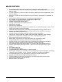
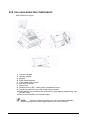
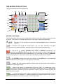
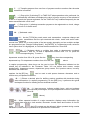
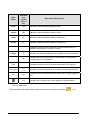
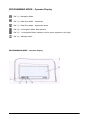
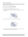
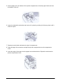


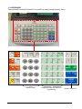
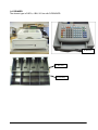
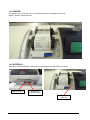
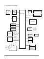
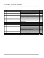
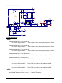
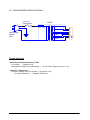
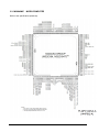
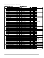

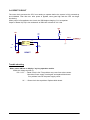
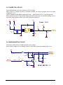
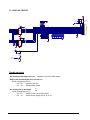
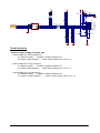
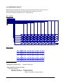
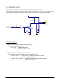
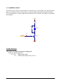
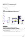

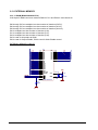
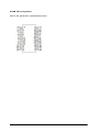
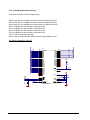
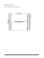

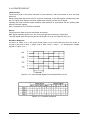
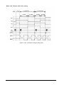
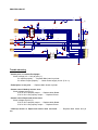
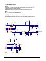

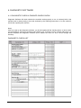
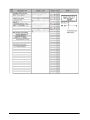
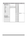
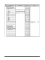
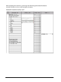
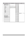
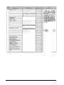
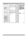
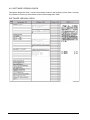

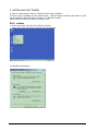
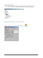
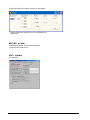
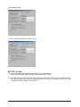
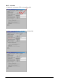
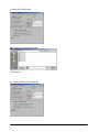
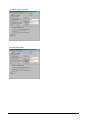
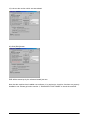
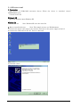
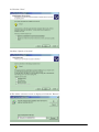
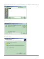
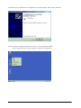
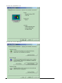
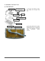
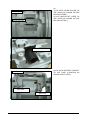
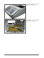
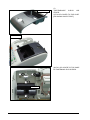
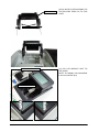
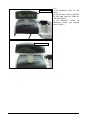
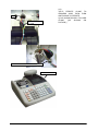
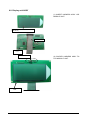
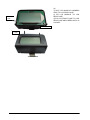
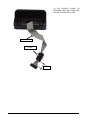
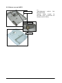
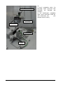
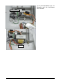
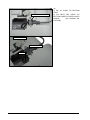
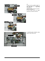
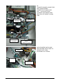
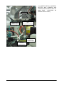
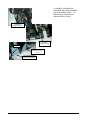
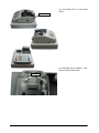
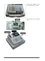

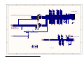
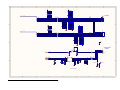
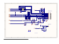
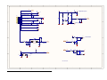
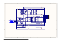
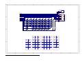
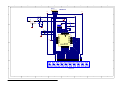
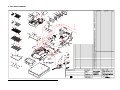

![[SPT-3000] e](http://vs1.manualzilla.com/store/data/005667089_1-a5f3766b3193f6552f250995926a69c5-150x150.png)