1
§
I
I
I
o
I
I!O 01 'ON
6
€3
a
a
a
a
G
5
r
'
I
r
- ..................................................
.a w ! J q n i g l ~ e ~ l a~d dl nj ! ~
...................................................... alez!Jqni 'Jahal d o i s H!J.
5
....................................alg3liqnl 'slea~)/lohlda l y m u y a l p u e ~ ~ a l p l
9
..............................................
. a l e 3 v q n ~' a 6 e y u i i I~!~S/~IIIOJU~
- 5
..........................................................
a l w p q n l ' u ~ laA!MS
d
................................................. a ~ e z l ~ q n' syd ~ u e l a;eldJolelS
3
............................................a l e ~ q n 7i e a 5 uo!u!d JOION . y a m s
---
.................................................
I u o ! : l p L ' o 3 [ ? , a u 3
'sEn!J y ~ e d s
. . . . . . . . . . . . . . . . . . . . . . . . . . . 133dSu1'SUC!l33uU03 1831~33ai3
11vrSpe3; 6nld JESS
~
3. Inspect spark plug hole threacls and clean before installing plugs.
1. Compression Check
e n g i n e several times
1. Rrmovr spark plug wires and all spark plugs and check condition.
2. Uisconnwt or install a ground wire. as i:tstructed on wiring diagram (see
"Wiring Diagram" by model, following). to render ignition system inoperative while perforn~ingcompression check.
3. In3tall ronlprrssion gauge in spark p111ghole.
4. Crank e ~ ~ g i rthru
w at lrast 4 compression strokes at wide-open throttle
'
( W N ) tu oLtain higliest possihle reatl~ng.
5. Clirck and rrrord rornprrisior~of each cylinder. Variation of more than 15
Ibs. per sq. in. (1 .OT,Okg/cm') between cy!inders indicates that lower comorcssion cylindrrs a r r in some way defective, such as worn o r sticking
piston rings and/or scored pistons and cylinders.
6. Cornlr.ssion check is important because an engine with low or uneven
comprcssiior cannot b r tuned successf~~lly
to give [teak perforn~ancc.11is
essential, therefore, that improper compression be corrected before proceeding with an engine tuncup.
7. If powerhrad shows any indications of overheating. such asdiscolored o r
scorched paint, inspect cylinders visually thru transfer ports for ~ o s s i b l e
srorir~g.It is possil,lo for a cylinder :o bescored slightly and still have comparativtaly good rcmpr-:sion.
8. Check watrr pump. A failure may bc cause of overheating.
2. Spark Plugs Inspection and
Adjustment
1. I n ~ p e c each
t
spark plug for m ~ k and
e heat range. All plugs must be of the
same make and number o r heat range.
2. Rcrnow spark plugs, clean and Inspect. If center electrode IS eroded
(Figure 1). replace w ~ t hnew spark pluglisted rn"T~rn~rr~/S~nchroniz~ng/
Adjustmg" section, follow~ng.
-
*-
- ----- *T
-i
nalerlnl which might become dislodged d u r i n g c l e a n i n g
operatlan.
4. Install spark plugs in engine with new gaskets and tighten to 17 ft. Ibs.
(2.35mkg) torq!le. Improper installation is one of t h e greatest single
causes of unsatisfactory spark plng performance.
5. Always use n new gasket and wipe seats in head clean. Gasket must be fully
compressed on clean seats to complete heat transfer and provide a gas
tight sral in the c)-linder. For this rrason, as well as t h e necessity of maintaining correct plug gap. the use of correct torque is extremely important
during installation.
3. Water Pump Installation
REMOVE WATER PUMP
1. Set gear housing in vise in upright position with skeg held between blocks
of wood.
2. Remove centrifugal slinger from drive shaft.
3. Remove water pump body assernhly.
4. Remove water pump and remove impeller and impeller drive pin and face
plate.
5. Cheek impeller face plate and water pump insert closely for wear o r
damage.
6. Remove water pump base assembly and water inlet tube (if equipped).
7. Remove "0" ring and oil seal from base plate assemldy and watch for
shims under hase assembly.
SHIMMING of WATER PUMP BASE
Lower units, with a ball bearing on the driveshaft, must b e s h i n ~ m e dto "Zero"
clearance between drive shaft ball bearing and water pump base, as follows:
1. Position a new gasket to lower unit over water pump studs.
2. Install original shims, plus .020" ( S l r n m ) additional shims, above drive
shaft bearing. This will result in a n "over-shim condition".
3. Lubricate seals in water pump base. Remove "O" ring from water pump
base to rase installation for measurement only.
4. Position water pump hase into lower unit: push down firmly.
5. Measure gap between water punlp base gasket and water pomp base with a
feeler gange.
6. T h e gap measured. p l ~ i s.002" ( . G I mm), is t h e correct amount ofshims to
remove. This will result in "Zero" gap between water pump baseand drive
shaft bearing,whirh is correct and will result in .002" compressior~of the
gasket.
EXAMPLE: If gap measured is .010' (.25mm), remove .012"
(30mm) shim. If gap measured is .005" (.13mm), removo .007"
(.18mm) shim.
7. hferc 110-7545 models d o not use a gasket. If gap measured is .005",
remove .W5" shim to give "Zero" gap.
8. Install "0"ring o n water pump base and install base t o lower unit.
NOTE:
Louwr unlts uxth
~ ~ ~ p p drive
e r d shaft beanngs d o not require shim-
ming of water pump h r .
-
b Centbr E l e c t r o d e
Figure 1. T h u n d e r b o l t Plug
a - 1!32 (O.Omm)
INSTALLING WATER PUMP
1. Install water pump base to face plate gasket, stainless steel lace plate and
face plate to water pump cover gasket.
p u pau!slqos!
~
ainlx!m uuaal ool p u n ~ ( ~ M O as!fiqJop
IS
Cdu!uin~a n u y u o 3 .S
.paads dn sy3!d au!2ua pue
REPWlRS and ADJUSTMENTS
For carburetor repair procedures (disassembly, cleaning, adjustments and
reassembly), refer to "Fuel Systems" in Service Manual (by carburetor type).
-
a Fuel O u t k,t
b - Diaphragm
c Check Valves
d Fuel Inlet
Flgure 3. Fuel P u m p
for Mort Modela
-
a Screen
b
- Idle Mixture S c r e w
Flgure 2. l d l e Adjustment (Typical)
8. Check inlet v d s e hy reverse procedure. If leakage is encountered, check
for free operation and accurate setting of valves.
9. Worn or slightly warped valve will cause leakage. Replncewith new valves
for more accurate seatin$.
10. When installing fuel line fittings, we recommend aviation Permatex for
sealing. Apply sparin~lyto avoid clogging of fucl lines.
) 2-CylinderModels
,
3
'
1. When starting a cold engine, choke shutter must be fully closed. Adjust
choke linkage and choke return spring for fast, positive action of choke
shutter.
2. It may be necessary to readjust the qarburetor idle mixture scrsw up to
Yh-turn with each change in brand of gasoline to compensate for varying
volatility snd differences in relining process.
CAUTION: Do not u s e Liquid Neoprene o n fuel Ilneflttlngs.
Neoprene Is recommended only for e x p o s e d dlectrlcal connections. Permatex is available thru all local hardware
stores.
b
11. Reassemble fuel pump(s), using new gasket(s).
.
FUEL LINES and FILTERS
3-4 and &Cylinder Models
Hard starting is often traced to improper choke shutter operation. Adjust
choke Ilrtkage and choke return spring for fast, positive action of the choke
shutters.
5. Fuel System
-
FUEL PUMPS VACUUM TYPE (Figure 3)
1. Wash all parts thoroughly and use compress~dair to dry.
2. Inspect each par: carefully for wear or damage.
3. Replace pulsator diaphragm with new, if old diaphragm shows the least
sign of deterioration.
4. Be ;ore that valve seats provide flat contact area for valve disc.
5. T i g h ~ e relbows
~
and check valve connections firmly when replacing.
6. Do not usc I'ermatex on valve retainer gasket.
7. Check valves after reassnmhling fucl pump cover by blowing thru outlet
hole. Air should blcw thru valve but should close immediately when
attempting to draw air thru it.
1. Inspect fuel lines for kinks, leaks and restrictions and correct any defects
found. If necessary, remove fuel lines and blow out with compressed air to
remove any f o r e i g ~material.
~
When reinstalling lines, besure that they are
not twisted or kinked. thereby causing restrictions.
2. Clean or replace fuel line filter element(s) as follows:
a. Remove filter cover(%)and elernenr(s).
b. Wash parts in solvent nnd dry with compressed air.
3. Reinstall eIe~nent(s).
NOTE: If a romplninr of poor high speedperformane mists.fuelpumpprcssure test should be performrd.
FUEL PUMP DIAPHRAGM
A defective fuel pump diaphragm (Figure 4) is often mistakingly diagnosed
ignition trouble. A tiny pin-hole in diaphragm will permit gas to enter crankease, causing that particular cylinder to wet foul the spark plug at idle speed.
At higher speeds, gas quantity is limited and plug will fire normally.
1
a - Gasket
-
c - Screw
I
e - "0"R i n g g D i a p h r a g m
-
b C h e c k Valves d - filter S c r e e n I Cover
F l g u m 4. F u e l P u m p A-66530A2
h
- Base
6. ignition System
I
1
*
i
1
r
1. Use Mercury Marine Thunderbolt Ignition Analyzer (C-91-62563A1). All
ignition conlponents must be checked.
2. Maker Points (1975 Merc45): Maker points (with some timeon them) will
show discoloration. but this is not a reason for replacement. Points.that
show zero resistanceacross contacts, are satisfactory. Maker points, which
show slight resistance, may affect idle operation. Points, which show high
resistance, may cause 3 malfunction cf ignition system and subsequent
loss of spark.
3. Complete "Timing/SynchronizinglAdjusting", following, t o assure correct rngine operation.
Sec " T r o ~ b l e ~ h o o t iThunderbolt
n~
Ignition", information, /ohwing.
7. Starter Motor and Solenoid
STARTER MOTOR
greaye disso!ving wlvent for cleaning armature o r field coils, as insulation
will be damaged.
3. Test pinion g w r atid screw shaft. Pinion gear must move freely on screw.
Check pinion gcar to src :hat it is not chipped c r worn excessively. Check
for bent armatirre shaft.
4. Check that t1r11sl1holdrrs are not deformed o r bent and will properly hold
brushes again51 cvlnmu:ator.
5. Check brush spri:rp. It tmsion is insufficient. the hrushes will arc and
wear very rapidly.
6. Check condition of brushes. If pit:ed o r worn to one half their original
length, they should be rrplaced.
7. Check fit of armature s l d t in hushingof drive end plate. Shaft should fit
snugly in bushing. If hushing is worn, it should be replaced. Apply No. 10
oil to this b u s l ~ i r ~before
g
reassembly. Avoid excessive lubrication.
8. Check fit of bushing in commutator end plate. If this bushing is damaged
or worn excessively, enrl plate bushing or assemhly should be replaced.
Apply NO. 10 oil to t l ~ i sbushing before reassembly. Avoid excessivelubrication. Lubricant forced onto commutator will gum and cause poor commutation, with resultinfi decrease in starter motor performance.
9. Inspect armaturc commutator. If commutator is rough o r out-of-round, it
st~ouldbe turr~eddown and under-cut. Inspect points, where armature
conductors join commutator bars, to make sure that it is a good firm connection. Burnzd commutator har usually isevidenceofs poorconnection.
10. T o remedy any of preceding conditions, refer to the Service Manual.
11. Reassemble starter motor and lubricate pinion gear and screw shaft with
No. 10 oil.
12. Check return spring for normal tension. Pinion must return from engaged
position smoothly and rapidly.
TESTING SOLENOID
1. T u r n selector switch of Magneto Analyzer to Position No. 2 (Distributor
Resistance) and clip small red and black lead together. .
a - C o n n e c t S m a l l Red Test L e a d
-d - C o n n e c t S m a l l B l a c k Test L e a d
.T e r m l n s l s on S o l e n o i d
b "S" T e r m i n a l
c "I" T e r m i n a l
Testing Starter Motor
1. Be sure that brlttrry is fully charged and at least 70 ampere hour capacity
hciore testing starter motor. Many starter motors are needlessly disasserr~bledwhen battery actually is at fault.
2. Using a voltmeter, connected to :he starter motor positive terminal and
ground, check battery voltage under load as follows: With voltmeter connected. turn ignition switch to Start position while observing voltmeter.
If voltage is 91/2 volts or more and starter motor fails to operate, repair o r
replace starter mdtor.
Clea~lngand inspection of Starter Motor
1. Remove starter motor and disassemble.
2. W i t h starter motor completely disassembled. except for removal of field
coils, component parts should be cleaned and inspected. DO NOT use
2. T u r n meter adjustnlrnt knob for Scale No. 2 until meter pointer lines u p
with set position on left side of "OK" block on Scale No. 2.
3. Unclip small rerl and black leads. (Figure 5)
4. Connect small red test lead to one I q e frrminal of solenoid and connect
small black tee! lead to other large terminal, as shown in Figure 1.
CAUTION: Do n o t c o n n e c t battory l e a d s t o l a r g e t e r m l n e l r
o f aolenold, or n i e t e r wlll be d a m a g e d .
5. Using 12-volt battery and jumper leads, connect positive lead tosmall "S"
terminal of solenoid.
6. Connect negative battery lend to "I" terminal of solenoid.
7. Meter pointer hand must move into t h e " O K block, o r solenoid is opencircuited a n 3 must he replaced.
8. With lead apart, "zero" meter to right side ofScale2. Check between "S"
and "I" terminal (2.1 to 2.7 ohms).
The lower HI'M is recommrnded for large, heavy, slow boats or for conlmercial
applications. T h e highrr RPM is recornmended for light. fast boats. T h e wide
RPM range will result in q w l c r satisfaction derived from m a x i n ~ u nper~
f r ~ r cconomy.
l
formance and mani~n~irn
WATER PRESSURE TEST (A-55664A1 or A-65614A1)
1. Water pressure at the rylindrr Mock should br chrcked whenever a n overhtating ror~Jitionis detected or susprrtrd.
2. A large kerl or othrr arrrssories, loratrd cm the boat bottom forward of
if the engine speed is too high, try a higher pitch o r the same pitch cupped.
Likewise, if engine speed is low, try a lower pitch prop. There normally is a
300-500 RPM change Iwlwrer! propeller pitches.
t h r nrutor, can cause what is mistakenly diagnosed as water pump failure.
3. A motor mountrd unusually high on the transom also can cause overheating. A solid, unrrstrirted water flow nlust he delivered to the gear
housing for maxin~urncooling and engine efficiency.
For dual installation. the llext higher pitch propeller may be best. For water
skiing, it may be h i r a t ~ l to
r use the next lower pitch; howevcr.use cautiondo not operate at f11l1throttlt: when using ski propeller and not pulling skiers.
I n this case, the I~rnpellrrhas too littlr pitch for the application, and
d a n ~ r r o u so v e r ~ ~ ) of
~ rthe:
d engine may result. If t h e propeller has too much
pitch for the a p p l i v ~ i o n :~ccrlrration
.
will be slow.
4. Insrall necessary fitting and watrr pressure hoseon thecylinder blockand
place water pressure gauge in ronvrnirnt position for viewing while
operating hoar. Water pressure at full throttle under any running conditions. i.e., turning, maneuvering, etr, must be 5 psi (Ibs. per sq. in.)
(0.35kg/rmz) or more.
FUEL PRESSURE (C-9140692)
Iug and ignition Data
1. Fuel pressure at the top carburetor should be checked whenever insufficient fuel is suspected, o r if other than Mercury Marine fuel tank is used.
Check "foreign" fuel tanks for the following:
a. Adequate air vent in fuel cap.
1). Fuel linr large enough (5/16-to-3/8") (8-to-9.5mm).
r. Filter o n r n d of pickup too small or clogged, or fuel pickup tube too
small. Ilsc: A-3233909A.1. Furl Pickup Assembly as a comparison.
2. lnsulfirirr~tfuel supply will cause engine to run lean, lose RPM or cause
piston scoring.
3. 'Tlw fuel pwssure gauge should he installed at the end of the fuel line that
lends to the upper carhuretor. Fuei pressure must be 2 psi (Ibs, per sq. in.)
( O . l - l l k e / c n ~ ~or) more at full throttle.
1-1
Me"
Model
LOW SPEED PERFORMANCE
For optimum low sprcd motor performance, we rrcommend that idle mixture
and idle HI'XI he readjustrd under actual operating conditions.
OPERATION at RECOMMENDED RPM
,
NOTE: Turn in all spark plugs finger-tigh before applying torque wrench.
Torque plugs to 20 ft. Ibs. (2.76111
kg).
5 Champion
QL7J.S or QL7J for countries other t
h
US.
l'lrr corrrrt proprllrr should he installrd on the tmglnr so that it will run at
Merc
Merc 45 Capacitor/Module Test
Model
I0 (2-CyI.1
15
:5
110
200
402
500
650
650XS
700
800
850
050XS
900
1150
1400
1500
1500XS
1500 V-6
1750 V-6
2cm v-6
..
2. Tl~underboltIgnition Anolyzer Meter 2 - 9 1- 6 ~ j 6 . 3I ~
) , red =ace 5
3 . Merc-O-Tro~icIgnition Analyzer (C-91-25213) $
-
-
IMPORTANT: Disconnect Stator Leads before Testing Stator Assembly.
Disconnect Stator Coil Wires before Testing Coils.
Mere Model
end Year
Tester Leadr to
200 (1975-76)
;/N 4377556 and
Below)
ZOO (1976-77-78
$N4403787 and
Above)
Between Yellow Stator W ~ r eand Ground
-1
R x 100
Between Yellow and Whtte Cod Wires
7.5-10
R x 100
R x 1000
(Htgh Speed) Between Yel!ow and Blue Cotl Leads
(Low Speed) Between Yeliow and Red C o ~Leads
l
6-8
5 3-6.1
R x 100
Between Yellow Stator Lead and Ground
15-20
R x 100
Between Yellow and White Coil Wires
Rx 1
Between Red and B!ue Coil Wires
aA-338-499iA
R x 1000 Between White and Blue Coil Wires
AA-33S5209A
-
R x 100
R x 100
nA-339-6119A
AA-339-6120L
Scale
Reading
R x 100
Witator Coll
A339-5566Am339-5589A8339-5590A MA-336-4470AHA-336-4469AAA-339-5209AAA-339-5566AA-33453 1 2 L
A-339-531 3A1A-339-5589AA-339-5590AA-33461 1 9 A
A-339-61 2 0 L
HA-338-4992A-
-
Between Yellow Stator Lead and Ground
Between Yellow and White Coil Wires
(Continued on Next Page)
15-20
180-340
5.2-7. .2
15-20
7.5-10
2. Adjust retard cable (Figure 1) so that approximately 3-10-4 threads 1%"
(3.2mrn)J ale exposed, as shown in Figure 1. Tighten jam nuts securely.
3. With twist grip held against idlestop,adjust advancccable (Figure 1) until
no d a r k exists in cable. Tighten jam nuts securely.
4. Hernovc remote idle lever from idle screw (on carburetor) and preset carburetor idle screw at i %turns (_+i/B turn) out from lightly seated position.
8. X.',tlt the ~ d l edjustment
e
knob (F1gure3) In "Run" posltlon, re~nstallthe
remote ~ d l elever onto carburelor ~ d l esrrew In the 9 o'clock pos~tlon.
9. D~sconnccttlmlnK I~ghta d tachometer from cnglne and remstall c n d n e
cowl.
DYNAMIC TIMING PROCEDURE
1. Place engine in a test tank and remove engine cowl.
R
-
c
.a - ldle Adjustment K n o b
-,*.
"""SJC10926
Flgure 3. ldle A d j u s t m e n t K n o b L o c a t l o n
a - T r i g g e r Link R o d
-
- - -.
-
.I
s
---.ri 1 0 9 2 3
ere 45 with
Phase-Maker Ignition
b Maximum S p a r k A d v a n c e S c r e w
c - Retard C a b l e
F l g u r e 2. A d j u r t m o n t L o c a t i o n s
2. Connect Timing Light (C-91-35507) to engine by connecting red lead to
No. 1 (top) spark plug and connecting black leads to 12-volt battery positive (+) and negativc (-) trrnlinals. Connect tachometer to engine.
Firing O r d e r
Spark Plug
Spark Plug G a p
Timing Moxirnum A d v a n c e
Throttle P i c k u p
Full Throttle RPM
Idle RPM
l s i n g l e Cylinder
AC-V40FFK & C h a m p i o n L78V
Not Adjustable
,198" BTDC
5" ATDC
4500-5500 RPM
650-800 RPM in Forward G e a r
(Approximatoly 9' t o 1 2 O ATDC)
Water P r e s s u r e (at Tell-Tale) 4 t o 7 psi (.281 t o .492kg/cm2)
IMPORTANT: lmmedlately after rtartlng englne, m a k e certaln
that w a t e r p u m p 18 operating (check for w a t e r d l r c h a r g e f r o m exh a u s t mllef h o l e s a t r e a r of drive r h a n houslng).
3. Start engine, shift into fwward gear and run at Yz-throttle lor approximstrly 5 n~inutosto warm up engine.
at 5000 RPM
4, Set idle tinting as follows:
a. With cngine in gear and running at 1000 to 1500 RPM, observe ignition timing while quickly closing throttle against idle stop. The timing
will flrlly retard to approxim;ltcly 18" 1020' ATDC, then will advance
slightly to 15' to 10' A'IDC as the idle speed approaches 600 RPM.
b. Adjust trigger link rod (Figure 2) to set idle timing at 2' below the
advance readingwhich is obtained as idle speed approsches 600 RPM.
TIMING ADJUSTPAEECTS
-
EXAMPLE: Tirnrngfully %tar& tu 18' ATDC a.s throttle h closed. adoanca
at 600 RPM; set ~ d ktlming (11 170 ATDC.
to 15" A7'I)C
-
.
I
5. Advance throttle grip until 22" to 26' BTDC is reached, thonadjust maximum spark advance screw (F~grrre2).to contact stop. Tighten jam nut
(on spark advance screw) securely.
6. Turn twist throttle grip against idle stop. Advance throttle grip until
throttle cam contacts cluster pin, then check timing. Timing should Im 14'
+ 2' ATDC. If throttle pickup is incorrect, readjust throttle cam, as required, to obtain throttle pickup at 14" +_ 2" ATDC.
7. Adjust carburetor setting a3 outlincd, preceding.
1. Remove top cowl, flywheel and module cover to expose maker-point set.
(Finrre 1)
2. ~ o cranksl~aft
k
to place cam follower at high point on cam (Figure 1).
Adjuvt point gap to .020n (.51mm) and reinstall flywheel. Torque flywheel
nut to specification in "Specifications" section of Service Manual.
3. Remove spark plug and iristall Dial Indicator (C.91-58222) into spark plug
hole.
4. Rotate crankshaft clockwise to find piston TDC (top dead center). Set dial
indicator at zero and lock set screw. (Figure 2)
5. Rotate crankshaft counterclockwise to place piston at .198" (5.03mm)
M'DC.
6. UsingVOAMeter (C-91-52iSl),set meter on R x 1000scale. Clip test leads
together and zero meter to right side of scale. Connect red test lead 10
l~nitioncoil white wire terminal and black lead to engine ground.
7. Turn twist grip throttle to open throttle to n~aximumsparkadvance point.
IFtpre 3)
G
.j. Tlghtm jam nut on spark advance screw after adjustment is made.
6. Close throttle w ~ t htwirl grip. Shut engine off and remove timing light.
4314385)and Merc I 10 (Below
.
. adjustment
t a r t e g i n information,
e a a u t idle rn~xturescrew
hest idle. aefer tocarburetor
%isforengine
is equipped with an
Serial No. 4304785)
Firing O r d e r
Spark Plug
Spark Plug G a p
Timing M a x i m u m A d v a n c e
T h r o t t l e Primary P i c k u p
Full Throttle RPM
ldle RPM
Water P r e s s u r e (at Tell-Tale)
*
j
Alternate Firing
AC-V40FFK o r C h a m p i o n L78V'
Not Adjustable
I
!
I
integral fuel pump carburetor. Follow proper idle mixture instructions.
Do not set carburetor !caner than necessary, as a lean setting causes hard
starting.
2. Set engine idle RPM ~ t n screw
p
to attain 650 to 750 RPM in forward gear.
,
MAXIMUM NEUTRAL RPM LIMITER
350 BTDC
I
Not Adjustable
4500-5500 RPM
1 1.
550.750 RPM in FOnuard Gear
4 t o 8 psi (.281 t o .562ka/cmz)
,
@ 4 5 0 0 RPM
* Merc 75's (bclow 4131610) and Merc
110's (below 412&60)
use AC-V40Fl;iM or Champion L76V
TIMING ADJUSTMENTS
1. Place engine in test tank and attach fuel line.
2. Install Timing Light (C-91-35507) by connecting large red lead to No. 1
spark plug, then connect one small lead to battery negative (-) post and
other lead to positive (+) post.
3. Start engine and shift into forward gear. Turn twist grip to full throttle.
4. Adjust maximum spark advance screw (Figure 1) until timing line on flywheel aligns with timing specification on starter housing decal. (Figure3
I
With engine r u l l n i n ~in ~ ~ e u t rgear,
a l loosen neutral RPM limiter screw
(located in the bottorn cowl!, Move limiter toward rear of engine and
tighten the screw only enough to placelight tension on the limiter. (Figure
3\
JI
2. Turn
twist grip to at tain 2400 to 2700 RPM. then tighten the limiter screw
securely. Recheck limiter HPhl by returning to idle, then opening throttle
I
to the limit stop. Readjust i l necessary.
3. Check that neutral RPh! limiter does not interfere with tlirottle operation
I
in forward gear. If it should interfere, move end of limiter toward cylinder
;
block and recheck neutral HPM.
I
NOTE: This odjustmenr must be accurate to -re
easy starting when engine
u cold.
a -Timing Decal
b - Timing Mark
F l g u r e 2. T l m l n g Mark Alignment
a - Maximum S p a r k A d v a n c e S c r e w
-
-
c ldle Mixture Screw
b Locknclts
d Idle RPM S c r e w
Flgurcs 1. Maxlmum Spark Screw and l d l e Speed S c r e w
CH./ADJUSTING
Merc 75 (Serial NO.4314385thw-4397536) and Met-c 110
(Serial Mom4304785-thPu4387436)
r
Merc 75
I Merc 110
tlinlnr mark (we rpechcation above) on starter housng. Adjust m a n mum advance screw (F~gnre1) untd end of screw just touches throttle
Itver. Tighten jar11 nut.
5.
ttlr0ttie with twist grip. s h u t engine offand remow riming Ligllt.
uose
.
,
CARBURETOR ADJUSTMENT
I
Flring Order
Alternate Fwng
AC-VIOFFK or Champion L78V
Spark Plug
Not Adjustable
Spark Plug Gap
T ~ m ~ nMaximum
g
30" BTDC
35" BTDC
Advance
Not Adjustable
Throttle Pickup
Full Throttle RPM
4500-5500 RPM
Idle RPM
650-7.50 RPM (in ~ear)l650-750RPM (in Gear)
(Approx loo
(ApprOx. 15" ATDC)
Water Pressure
4 to 8 psi (.281 to .562kg/crn2) at 5000 RPM
(at Tell-Tale)
I
1. Restart ecglnr and .idjsst tdle rwxture for "best idle" In forwardgear. See
carburetor adlu5tmrut ~nformation,prcced~ng.
2. Set ~ d l eRI'M to y r r c ~ f ~ c : ~ tin~ oforward
n
grar.
1. W ~ t henpnv rnnnlng In nrutral. Ionsen neutral RPM lim~terscrew.
(F~gurt.2) M o \ e Irmlter toward rear oT, engme and tighten screw only
enough to place !~ghttcnslon on I~mrter.
2. Turn t w ~ s tgrip to attaln 240&2700 RPM, then t~ghtenllrn~terscrew
securely. Recheck RI'M hy returnmg to idle, then open throttle against
I ~ m ~ t eReadjust
r.
111nlterIT necessary.
3. Check that neutral HPM h m ~ t e does
r
not interfere wlth throttleoperation
in forward gear. If limlter interferes, move its back edge toward cylinder
then recheck neutral RPM.
NOTE: ~ h &judlu.tmnu
b
MOST BE m u a u
.-
r
TIMING ADJUSTMENTS
1. Placc englne In a test tank and connect fuel line. Pre-set idle mixturescrew
at 1Yz turns ( t Y 4 turn) out from seated pos~tion.
2. Install T ~ m i nLight
~ (C-91-35507)by connecting red lead to NO. 1 (top)
spark plug and connecting black leads to battery positive (+) and negative
(-) posts.
!
1
I
MAXIMUM NEUTRAL RPhl LIMITER ADJUSTMENT
I
I
I
; A d \ a n c ~twist grlp until timlng line on flywhed aligns with maximum
to m3u.e t
!
qstarting
i
I
i
1
i
1
i
v~un
engine L cold.
.
P
-
r
r
l
T
a ,
'h
.-
A"-\
E
it
T----------"
1
I
f
i
i!
5
a
u-.
-
c - Idle Mixture Screw
d Idle RPM Screw
b Locknuts
Flgure 1. Maximum Spark Advance Adjuswlent
a Max~mumSpark Advance Screw
-
...*
-
-
- . --
- --- .3 08395
Neutral RPM Limiter
b Adjustment Screw
naun 2. Neutral RPM Limiter Adjustment
-.
-
I
TiMlNG/SYNCH./ADJUSTlNG
Mere 35 (Above Serial No.
4397537) and Merc 1 10 (Above
Serial No. 4387437)
TILLER HANDLE DECAL PLACEMENT
1. With engine in neutral and twist grip turned against neutral RPM limiter.
"Start" on twist p p decal must align with arrow on tiller hnndle. (Figure3)
'
I
I
07822
-
a Arrow
b
- "Start"
Figure 3. Tlller Handle and Decal Alignment
2. Repositiont w i s t grip, if necessary, by removing2 allen head screws at tiller
handle knuckle (Figure 4) and realign gears, as necessary, to align "Start"
with arrow. Reinstall allen screws.
,
Firing Ordor
Spark Plug
Spark Plug Gap
Timing Maximum Advance
Throttle P i c k u ~
Full Throttle RPM
Idle RPM
Water Pressure (at Tell-Tale)
I
I
I
Alternate Firing
AC-V4OFFK or Champion L78V
Not Adjustable
Align Timing Marks
Not Adjustable
4500-5500 RPM
650-750 RPM in Gear
4 to 8 psi (.281 to .562kg/cm*)
at 5000 RPM
A
TIMING ADJUSTMENTS
1. Place engine in r test tank and connect fuel line.
2. Pre-set carburetor Idle mixture screw 1% turns out from lightly seated
position.
3. Connect Tlming Light (C-91-35507) to No. 1 (top) spark plug.
"
a
-*-,.-
-
-.
..
~
- h l a x ~ ~ n uT~ming
m
Mark (on Flywheel)
-,v.
"S'
'
as*-,
~ 1 1 0 9 7 3
b - Timmg Al~gnmentMark
Flgura 1. Maxlmum Spark Advance Tlmlng Mnrkr Allgned
4. Start engine and shift into forward gear. Advance engine RPhl until maxi-
-
a Allen Head Screws
Flgslm 4. Tlller Handle Gear Reallgnment
mum timing mark on flywheel i s aligned with timing alignment mark on
starter housing, as shown in Figure 1. Adjust maximum spark advance
screw (Figure 2 ) so that end of screw just touches throttle lever. Retighten
nut on adjustment screw. Return throttle hack to idle and turn offengine.
Disconnect timing light.
-
b Bolt
a - Maximum Nout:al S p e e d S t o p
Figure 4. M e x l n r m Kairtrsl Speed Llmlter Adjuatment Only
Enelnos with a Tiller (Twist Grip) H a n d l e
on
MAXIMUM NEUTRAL RPM LIMITER ADJUSTMENT
a - Maximum
S p a r k Advance S c r e w
Figure 2. Maxlmum S p a r k Advance Adjustment
CARBURETOR ADJUSTMENT
1. Start engine and allow to warm up to normal operating temperature.
2. With engine running in forward gear, adjust carburetor idle mixture screw
to attain "best idle" in forward gear. Refer to carburetor adjustment information, preceding.
!
3. Adjust engine idle RPM to specifications with engine running in forward
gear. (Figure 3) Retighten nut on adjustment screw.
IMPORTANT: Maxlmum neutral opsed llmlier adjustment s t o p s
t h e rotation of llller handla-twlst grip w h e n throttle la a t specified
maxlmurn neutral opeed. T h b adjustment must be a c c u r a t e to
assure e a s y starting w h e n e n g l n e Is c o l d a n d prevent e n g l n e from
otartlng a t rnaxlmurn RPM.
1. With engine idling in neutral, loosen bolt (Figure4) just enough to enable
maximum neutral spwd stop (Figure4) to slide back-and-forth, then turn
twist grip (advance engine RPXI) to 2400-2700 tUJhl. Without turning
twist grip, position and secure maximum neutral speed stopagainst neutral
speed limiter followr: (Figure 5) This will stop throttle at nlaximunl
neutral speed. Recheck adjustment to see if maximum neutral speed stop
stops the throttle at 2400-2700 RPM. Readjust if necessary.
2. Shift engine into forward nnd check that neutral speed stop does not interfere with throttle operation in forwardgear. If stop interferes, move back
edge of atop toward cylinder block.
a - Arrow
a - ldle RPM Screw
Flgure
3. l d l e RPM Adjustment
-
07822
b "Start"
Flgure 4. Throttle Handle a n d Throttle Decal Alignment
TILLER HANDLE and THROTTLE DECAL ALIGNMENT
I U'lth engine nnt running, shift into rleutral position and turn twist grip
" ~ throttle
1
is against maximurn neutral stop. The word, "Start", on
' h t t l f ! decal must be aligned with arrow on tiller handle, as shown in
re 4. If "Start" does not alikm with arrow, refer to steps, following:
a. R e m o v ~(and retain) 2 screws (Figure 5) which secure tiller handle to
englne.
h. Reahgn gears (Figure 5), as necessary, to align "Start" with arrow.
c. Hr~nstalltilltr handle to e n p e with 2 screws. Tighten screws securely.
"
'
t
v
.Ylr
--.%
..
" +
07839
a - Allen '!cad Screws (One Hidden)
Flgure 5. Tlllsr Handle Gear Realignment
-
b Link Rod
a - Elastic Stop Nuts (2)
Flgure 1. Mexlmum Spark Advance Adjustment (Model wlth Adjustable Elastlc Stop Nub)
Merc 200 (All Models, except
Electric Mo els, Serial No.
4709593 and Above)
Firing Order
.
Spark Plug
Spark Plug Gap
Timing Maximum Advance
Throttle Pickup
Alternate Firing
AC-V4OFFK or Champion L78V
Not Adjustable
33" BTDC @ 5000 RPM
Below Serial No. 4102790 - 2'
BTDC to 2" ATDC; Above Serial
NO.4102789 3' to 7' BTDC
4000-5500 RPM
Full Throttle RPM
Idle RPM
550-650 in Gear (Approx. 10°ATDC
Water Pressure (at Tell-Tale) 6 to 8 psi (.422 to .562kg/cm2) at
5G00 RPM
-
1. Place engine in test tank and connect fuel line.
2. Pre-set carburetor idle mixture screw at 1% turns out from lightly seated
position.
3. Connect Timing Light to No. 1 (top) spark plug.
.,,,A
I
L
.. --A 1102.5
- Jam Nut
b - Link Rod
Figure 2. Maxlrnurn Spark Advance Adjurtment (Model wlth Adjurtable Llnk Rod)
n
4. Start engine and shift into forward grar. Advance throttle to full throttle
RPM and adjust 2 elastic stop nuts (Figure I ) or adjust link rod (Figure2).
that timing mark on flywheel is aligned with 33' BTDC markon rewind
ntarter housing, as shown in Figure 3. lletighten elastic stop nuts (Figure
1) or jam nut (Figure 2) and return throttle back to idle.
a - Full T h r o t t l e S t o p S c r e w
F l g u r e 5. Full T h r o t t l e S t o p A d j u s t m e n t
a - Timing Mark o n Flywheel
CARBURETOR ADJUSTMENT
F l g u m 3. T l m l n g Mark A l i g n m e n t
6.-
.
1
,
.
,..
a - T h r o t t l e Pickup S c r e w
.
+
-
,-'
b
.
1. Start engine and allow to warm up to normal operating temperature.
2. With engine r u l n ~ i n gin forward gear, adjust carburetor idle mixture screw
to attain "best idle" in forwardgear. Refer to carburetor adjustment information, preceding.
3. Adjust idle RPM to specifications with engine running i n forward gear.
(Figure 6 ) Retighten nut o n adjustment screw.
--
a
10975
- Carburetor Cluster Pin
F l g u r o 4. T h r o t t l e P l c k u p A d J u s t m o n t
.
. .&
5. With engine running in forward gear, advance engine speed so that timing
mark on flywheel is aligned with specilied throttle pickup, thrn adjust
throttle pickup screw (Figure 4) so that end of screw just touches carl~urrtor cluster pin. as shown in Figure4. Retighten nut o n adjustment screw.
Return engine speed hack to idle, turn off engine and disconnect timing
light.
6 . W ~ t hw g l n r n o t runnlng, n ~ o v ethrottle arm to w~de-open-throttle(WOT)
and adjust full throttle stop screw ( F ~ g u 5)
r ~ to allow full carburetor
butter openlngat WOT. Makesurr that carbur-torshutte~docsnotuct*
a throttle stop. Allow .010"to ,015" (.25mm to .38mm) clearance between
throttle pickup screw and carburetor cluster pin.
a - l d l e RPM S c r e w
.
,.
.......;l 10966
F l g u r o 6. l d l e RPM A d j u s t m e n t
MAXIMUM NEUTRAL SPEED LIMITER ADJUSTMENT
IMPORTANT: Maxinium n e u t r a l cpssd lirnller a d j u n t m e n t atow
rolatlon of tlller hendl+tw:et g r l p w h e n t h r o t t l e it eE s p a c l f l e d
W X k w m neutral speed. This a d j u s t m e n t m u s t be aCCurat@ 10
easy atcrtlng w h e n e n g l n e Is c o l d and p r e v e n t engine f r o m
r B r t l a~t m a x l m u m RPM.
a
- Throttle Pickup S c r e w
-
b Carburetor Cluster Pin
Flgure 4. Throttle P i c k u p Adjustment
k&,
*.&- ---a
&
..
5. With engine runring in forward gear, advance engine speed so that timing
pointer is aligned with throttle pickup mark (5olid line) on flywheel
(Figure I ) , then adjust throttle pickup screw (Figure 4) so that end of
screw just touches carburetor cluster
as shown-in ~ i G r e 4Retighten
.
nut on adjustment scrcw. Return engine speed back to idle. turn offengine
and disconnect timini!" liebt.
"
6. With engine
running, move throttle lever to wide-open-throttlc
(WOT) and adjust full throttle stop screw (Figure 5) to allow full carbu
retor strutter opening at WOT. Make sure that carburetor shutter doesnot
act as a throttle stop. Allow .010" to .015" (.25mm to .38mm) clearance
between throttle pickup screw and carburetor cluster pin.
P L,
. ..
., .
.
a - ldle RPM S c r e w
Flgure 6. ldle RPM Adjustment
MAXIMUM NEUTRAL SPEED LIMITER ADJUSTMENT [for Models with Tiller (Twist Grip) Handle]
ir
E
IMPORTANT: Moxlmum neutral s p e e d llmlter adjustment s t o p s
tho rotation of tiller handle-twlst grip w h e n throttle Is a t speclfled
maxlmum neutral speed. This adjustment m u s t be a c c u r a t o to
assure e a s y startlng w h e n e n g i n e Is c o l d a n d prevent e n g i n e from
rtartlng a t maxlmum RPM.
-.A 1C974
a - Full Throt!le S t o p S c r e w
Flgure 5. Full Throttle S t o p S c r e w Adjustment
i
CARBURETOR ADJUSTMENT
,/-
1. Start cnglrlc arid allow to warm up lo rlormal oprratlng temperature.
2. Wtth engne rrrrlnlngm forward gear, adjust carburetor idle mlxturescr@'
to altaln "best ~dle"In forward gear. Refer to carburetor a d p t m e n t id@
rnatlon, precedmg.
3. Adjust Idle RPM to speclficstions wlth engine runnmg in forward 6CU
(Figure 6) Ret15hten nut on adjustment screw.
uv
-
c
'
i
.107&
a - Maximum Neutral S p e e d S t o p
b Bolt
7. Mexlmum Neutral S p e e d Limiter Adjustment ( f o r Models
wllh Tlllar Hendle)
X
rrr
-
; U'ilh pngine running in forward gear,advanceengine speed to full t l ~ r o t t l e
.%XK).5200 RI'M. Adlust maximum spark advance screw (Figure 5) until
liming mark (straight line) on flywheel is aligned with notch in timing
window, as slioun i r ~Figurc 4. Return engine speed back to idle and turn
off engine. D i s c o ~ r ~ ~timing
e c t light.
Figure 2. Throt:le Pickup Tlmlng Markr Aligned
o - Maximum Spark Advance S c r e w
Flgure 5. Maxlmum Spark Advance Adjustment
a - J u s t Touching
-
b Turnbuckle
Figure 3. Thronle Pickup Adjustment
r
7-
-D
'
.
-
Y
v-
, ,
i'
&>AJ*A
%"
-
"I
--. --A 073%
a - h l a x i m u m T m ~ n gMark Al:gned with N o t c h in T i m i n g Window
Flagre 4. Max!mum Timing Marks Allgned
!$?-
1
L
k'
&k.-..
/
[
I
-
2-
---
a - S e c o n d a r y Pickilp S c r e w
.
1
.-
-..-1910987
Flgure 6. Secondary Plckup Screw Adjustment
-?--
-*-
$ CARBURETOR ADJUSTMENTS
1 . Start enginr and al1l.w it to warm u p in forward p a r .
2. Adjust rarhuretor id!!, rnlxturc: screw to attail, best idle in forward gear.
See carburrtor atlj~:stmcntinformation, preceding.
1. Adjust enginr idle Hl'hl as follows:
a. With cnginr: in wntpr, connect electrical harness and fuel line to
engine. St.~rter~gir~tand allow to warm up.
b. With throttle: cablr barrel removed from barrel retainer, adjust idle
RPhl t o S(0-650 itiW with engine running in forward gear. (Figure9)
Hetightcr~nut on adjustment screw.
c. With en4 of throttle cable connected to throttle lever, hold throttle
lever spainst idlc stop. Adjust throttle cable barrel to slip into barrel
retail~eron whle anchor bracket with a very light preload of throttle
lever against itllr stop. Lock barrel in place.
d. Check preload o n throttle cable by placing a thin piece of paper
between idle strip screw and idle stop. Preload is correct when paper
can be rrmoved without tearing but hassome dragon it. Headjust cable
barrel. if necessary.
*. -
5
1
Ll
-..
\
rA
r_.e.Y
-
.I
. .-d
1
A
07377
IMPORTANT: Excessive preload an throttle cable wlll cause dlfflculty when shC3lng from fomard to neutral. (Readjust throttle
cable barrel, If necernary.)
b - Secondary Throttle Pickup Screw
c Secondary Cluster Arm
Flgure 7. Adjusting Secondrilty Throttle Pickup
a Just Touching
-
6. With engine not running, position spark advance lever agnirlst maximum
spark stop. DO NOTactuate throttle lever. Adjust secondary throttle pickup screw (Figure 6 ) so that end o f s c r ~ w
just tourhessecondary pickup arm
on carburetor cluster, a s shown in Figure 7. Retighten nut on adjustment
screw.
7. W i t h engine not running, move throttle lever to wide-open-throttle
(WOT) and adjust throttle stop screw (Figure 8) to allow full carburetor
shutter opening at WOT. Make sure that carburetor shutter does not act as
a throttle stop. Allow ,010" to .015" (.25mm to .38mm) clearance between
secondary pickup screw nnd secondary pickup arm o n cnrburetor cluster.
-
a Idle RPM Screw
Flgure 9. ldle RPM Adjustment
@
--
sia4, L L ,
-
-..--.
..
"
i ----d-e&wd
a Full Throttle Stop Screw
Figure 8. Fdil Throt3e Stop Adjurtnont
ra
10gsa
Install Timing Light (C-31-35507) by connecting red lead to No. 1 (top)
spark plug and connecting black leads to 12-volt battery positive (+) and
negative (-1 pests. Connect tachometer to engine.
With engine running in forward gear, open throttle to align timing mark
(straight line o n flywheel rim) with throttle primary pickup specification.
(Figure 3)
...
a - Carburetor
i
..
"
I .
.
1
03797
c - Just T o u c h i n g
b - Actuator Plate
Cluster
Flgure 5. T h r o t t l e P r i m a r y P i c k u p A d j u s t m e n t
7. With engine running in forwardgear at WOT,determine engine RPM with
t u c h o m r ~ r rllse
. this HPM to select correct maximum spark advance from
~ t l preredinl;
r
chart. With rngine running in forward gear at WOT,adjust
maximum spark stop screw to align timing mark on flywheel rim with corresponding drgrre m a r k on timing decal. Tighten locknut. (Figure 6)
8. Close throttle to idle position. Shut engine off and removeTiming Light.
9. With distributor adaptor held against maximum spark stop screw (but not
actuating economizer collar spring), adjust throttle secondary pickup
screw (Figure 4) to juut touch secondary pickup arm on carburetor cluster.
(Figure 7) Tighten locknut.
a - Screws
b
- Throttle Actuator
Plate
c - Throttle Secoridary Pickup S c r e w
F l g u r e 4. T h r o t t l e A c t u a t o r P l a t e A d j u s t m e n t
5. 'X'ith throitle I~ositionedas in S t r p 4, lunsm 2 actuator plate srrews
(Figure 4) and rotate actuator late, as necessary, so that primary cam just
touches primary pickup lever on carburetor cluster (Figure 5), then
tighten screws.
6. Due to the electronic timing characteristics of this ignition, it is necessary
to run the engine at widr-sprn-throttle (WOT) and to know the approximatr RPhl while adjusting the maximum spark advance. Hefer to the
chart, following, for maximum spark advance settings at differing RPM
while at wirle-oprrr.throttIt*. Engine R P M will vary, drpending upon prop e l k t pitch and waror level in tes! tank.
W T E : The engine may he tirnrl on o t m d , hut it must he tirnrd at uride-openthrottle.
-
Maximum S p a r k S t o p S c r e w
b Full T h r o t t l e Stop
c - Idle RPM Screw
F l g ~ ~ 6.
r eStop Screw Locations
--
Screw
-. d:'
).
A:,-
c-3
Actuator Plate
Primary Carn
b
3%
s-
- . . . 0984
- Carburetor Cluster Primarj eve
-
c -Just Touchina
Figure 2. Primary Throttle Pickup Adjustment
IMPORTANR Electroolc tlrnlng characterlstlcs of this lgnltion
system require that, when adjustlng maximum spark advance, ltlr
necessary to set the maxlmum spark advance at 32" BTDC to
attain 30" BTDC spark advance.
a - Secondary Pickup Screw
Figure 4. Secondary Pickup Screw Adjustment
9
K)!
I?
-+b
9
i
i
'
-%----L
..
-
---%.
f .J
.
-\A
*
-a"A--
,
a - Maximum Spark Advance Screw
Figure, 3. ldrxlmum Spark Advance Adjustment
1
.J
"1 1097;
.
.
- -
- -
Figure 5. Full Throttle Stop Screw Adjustment
6
,
!,,<?I,.,.
.A
;:t,
(.I
i"'ZI';
r , , ~ i r l vr i ~ i , n ~ nin
g
forward Rrar, open throttle to align 3"-5' marks
fl,-i~rt.i d w a l *ti11 tinting pointer. Adjust the screw between throttle
a,l,l
*!'ark nrnl. R S necessary, to cause the throttle actuator cam to just
tout!, tl~rottlrlever pin. (Figure 2) Tighten locknut.
,,It
r;.
i
L '&.,--,-..
a
-- .- Belt Alignment Mark
b -Timing Pointer
c - Cast Tabs Aligned
74".
Figure 1. Distrlbutor Driva Belt Ailgnment
07346
I
TIMING ADJUSTMENTS
-
-
a - Just Touching
c Throttle Lever
b Throttle Actuator Cam
d Adjustment Screw
Figure 2. Throttls Prlrnsry Pickup ~djurtmont
-
b - Spark Stop Screw
- Just Touching
a Spark Advance Arm
1 . Place engine in a test tank and connect electrical harness and fta-1 Hne 1
2. Proset carburetor idle mixture screws at one turn out fromseatedposition
c
Figure 3. Adjusting Maximum Spark Advance
-
a Throttle Arm
-
b Throttle Stop Screw
Flgura 4. Adjusting Full Throttle Stop Screw
I
4366882 and Above) with
Distributor-less ignition
a - Throttle Actuator C a m
b - Secondary Pickup
F l g u r e 8. S e c o n d a r y P i c k u p
Firing S e q u e n c e
Spark Plug
Spark Plug G a p
Timing M a x i m u m
Throttle P r i m a r y P i c k u p
,
-
...
CARBURETOR ADJUSTMENTS
.
~
1 . Start engine and a11ow it to warm up in forward gear.
2.
carlluretor mixture screws to attain h s t idle in forward F a r
carburetor adjustment informniion, preceding.
3. Adjust engine idle R P M as follows:
see
I
a. With engine in water, connect electrical llarness and fuel line to
c:n~,ine. Start enginp and allow to warm (IF).
b. a l l 1 1 throttle cable hairrl rrmove~lfrom barrel retainer, adjust idle I
RPM to 650-750HPM with engine running in frrrward gmr. (Figure9)
Nrtigllten nut on adjuntmcnt screw.
c. With end of throttle cable connected to throttle lever, hold throttle
lever aprinst idle 5top. Adjust throttlr rable barrel to slip into barrel '
rrtainer on c a l k anrhor bracket with a vcry ligtit preload of throttle Ir
I
h e r against idlr stop. Lock barrel in place.
d. Cllwk prrlsad or1 throttlr cahle by placing a thin piece of papa )i
I)rtwrrr~idlr stop s c r ~ wand idle stop. Preload is corrcct whrn paper I
can t~ r m o v e d without tearing but trassome~lragonit. R d j u s t cable
h r r r l , if rirrt-~~:iry.
IMPORTANT: E x c e s s i v e p r e l o a d on t h r o t t l e c a b l e will cause dlfficult^ w h e n shlfllng f r o m f o r ~ d r dt o neutral. i R e a d j u s f fhrottle
c a b l e barrol, if necessarv.1
90" C o n s e c u t i v e
AC-V40FFK o r C h a m p i o n L78V
Not Adjustable
27" B T D C
2"-4" B T D C ( B e l o w S e r i a l No.
4423 1 12)
2" BTDC t o 2' ATDC (Serial No.
44231 12 a n d A b o v e )
Throttle S e c o n d a r y P i c k u p N o t A d j u s t a b l e
Full T h r o t t l e R P M
5000-5500 R P M
ldle R P M
550-650 R P M (5'43' A T D C ) i n Gea
W a t e r P r e s s u r e ( a t C y l i n d e ~ 2 t o 5 psi (.I41 t o .352kg/cm2) @
Block)
2000 RPM
TIMING POINTER ADJUSTMENT
i
A
\-
%--2rL
-..-- ,. ".
-- X . . U U - , ~ - I * l 10230
a - ldle RPM S c r e w
*
f lgurtt
9. Id!e R P M A d j u s t t n e n t
I
SAFETY WARNING: E n g l n e p o s s l b l y c o u l d s t a r t when
t u m l n g f l y w h e e l t o c h e c k timing p o i n t e r a d j u s t m e n t . Remove all s p a r k p l u g s f r o m e n g l n e t o p r e v e n t e n g l n e f r o m
rtatilna.
----
I
1. Removeall spark plugs and install Dial Indicator (C-91-58222A1, Figure 1)
into No. 1 cylinder (top).
2. Turn flywheel in a clockwisedirectiorl until No. 1 piston is at topdead center (TDC), then set dial indirator at "0" (zero) and tighten indicator set
screw.
------A_."
-----A,
---*.-.---___Y(
a - Dtal Installed I n t o N o . 1 C y l t n d e r
flg~ft? 1. Dlal l n d l c a t o r l n a t a l i e d I n t o No. 1 C y l i n d e r
i
- 10969
6. With n ~ g i s erunning in forward gcz.ir,advance e r 1 ~ i n e s ~ n : 0that
so
pointer is a l i p d with specilied rnaxim~rmspark advar~ceon tinling drral,
Adjust n i a x i m ~ ~ rspark
s~
advanre slop screw so that end of screw just
tourhrs spark Irvrr, as shown in Figure 5. Hetighten nut on adjustment
stop screw. Move throttle back to idle and turn offengine. Remove timing
light.
6. With engine not running, advance throttle lever to wide-open-throttle
( W W ) and adjust full throttle stop screw (Figure 6) to allow fill1 carbu.
retor shutter opening at WOT. Make sure that carb~nretorshutters do not
act a s a throttle stop. Allow ,010" to .015" (.75mm to .38mm) clearance
between throttle cam and pin on carburetor cluster when throttleis WOT,
as s h ~ w nin Figure 7.
CAREIL:RE?0R ADJUSTMENTS
1 . Start w p n e and a!lnw engine to warm up in forward gear.
2. ~ d j i i s tc a r h u r ~ ~ oidle
r mixture screws to attain best idle in forward gear.
Set: carl~uretoradjustment information, preceding.
3. Adjust engine idle RPM as follows:
a. With engine in xater, connect clectrical harness and fuel line to
enginr:. Start engine and allow to warn] up.
b. With throttle cable barrel removed from barrel retainer, adjrrst idle
IiPM to 550-650RPM with engine running in forward gear. (Figure8)
Retighten nut on adjustment screw.
c. With ond of tl~rottlecable connected to throttle lever, hold throttle
lever against idle stop. Adjust throttle cable barrel to slip into barrel
r r t a i r ~ r ron ciahle anrllor bracket with a very light preload of throttle
Irver a g a i r ~ii!lr
~ ~ stop. Lock barrel in place.
d. Ctieck prrlonrl on throttle cable by placing a thin picce of paper
b r t r e r ~ lidle stop srrew and idle stop. Preload is correct when paper
ran br removed without tearing but has some dr.y:orr it. Readjust cahle
barrel, if rlrcrssary.
IMPORTANT: Excessive p r e l o a d on throttle c c b l e wlll cause dlfflculty w h o n shlfilng f r o m forward to neutral. ( R e a d j u s t t h r o t t l e
c a b l e barrel, If necessary.)
-
.-
- --. -- .-...
-
. .-..
--..... ..09837
A
a Throltle Lever
b Throttle S t o p S c r e w
F i g u r e 6. Full T h r o t t l e S t o p Screw A d j u s t m e n t
L
.-..--.
" "
-
-.
*
.
a l d l e RPM S c r e w
F i g u r e 8. E n g l n e l d l e RPM A d j u s t m e n t
a - C a r b u r e t o r C l u s t e r Pin
b - T h r o t t l e Cam
Figurn 7. Full T h r o t r l e Stop A d j u s t m e n t
-
-
A
d
.3
10979
-
g,
.
J.[il.c
Merc 850 ( elow Serial No.
4366801)
Firing O r d e r
Firing S e q u e n c e
Spark Plug
Spark Plug G a p
Timing M a x i m u m
Throttle Primary Pickup
Throttle Secondary Pickup
Full T h r o t t l e R P M
Idle RPM
W a t e r P r e s s u r e (at C y l i n d e r
Block)
1-3-2-4
pi.l\ey until arrow (cast inlopolley) is pointingal 3 dots
over pulley and install pulley cover,
artti bolt. l'ttrque covrr bolt to 60 in. Ihs. (69kg-cnt).
,{i.rril,~ttr,r
,,,, ( ~ ! . ~ t ~ ~ . , ;I<.\-al.
.l
Siip drive helt
.YOTI.:: 1C'hrn in.dling timing belt on 4 a n d 6 q l i n d e r outbards with Thun&&A Ignition. the nrrow on the pulley may not d i p directly with the mark
on the flywheel. If h i s should occur. dip the arrow slightly clockwise (as
viewed from front of outboard). This will appear to be approximat~ly'/z-tooth
offi (Figure 2) lnstnlling the he& V2-tooih to the lefi (counterclockwise) will
make engine synchronization drffinr& and r a u k in rough engine operalion.
1
90" C o n s e c u t i v e
AC-40FFM or Champion L76V
Not Adjustable
27" B T D C
3'-5" B T D C
27" B T D C
4800-5500 R P M
550-600 RPM
2 t o 5 p s i (.I41 to .352kg/cm2)
@ 2000 RPM
'
DISTR18UTBR DRIVE BELT INSTALLATION
I. Rotate flywheel until 3 dots o n flywheel timing decal are aliened with
center of distributor shaft. (Figure 1)
,
P l g u r e 2. Allgnmsnt %-Tooth Clockwise
TIMING ABJUSTMENTS
a
-
b 3 Dots o n Timing Decal
- Arrow
Flnure 1. Dlstrlbutsr Drive Belt lnstallatlon
1. Piace engine in a irst tank and connect electrical harness and fuel line.
2. Prrss r n r h u r r ~ o ridle mixture scrrws 1Yc turns out from seated position.
3. Install Timing I,ip,Iit (C-91-35507) by connecting rrd lead to KO. 1 (top)
spark ping and cnnnrcting black leads to 12-volt hattery positivr: (+) and
ncgativc (-) posts.
4. Wrih err@ne r u n n i n ~in iorward gear. move the throttlelever to alig113~to
So DI'UC on timing deral with timing pointer. (Figure 3)
5. With throttle positioned as in Step4.loose1l2actuatorplateretair1erbolts
(Figure 4) and rotatc actuator platr, as necrssary. s o that primary cam just
touches primr4ry pickup lever o n carburetor cluster. (Figure 4) Tighten 2
bolts.
6. Advance throttlr lever t o align 27' BTDC mark on timing decal with
timing pointer (Figtire 5) and adjust maximum spark stop srrew (Figure6)
to just touch distributor adaptor. Tighten locknut and rcchcck maximum
spark advance.
:,R c ~ r r r rc-npinr
~
tu idle and stop rngine. Remove Tinling Light.
a n 1111 cnfiinv .itopprd, ndvalrce throttle levrr to maxirnuin sp;irk
advance
w r r w tmt nnt :tctrrati~~g
the econon~izrrcollar spring, adjust thc sccondary
thro:tle pickup screw (E'igllre6) so that thesecondary pickup just touches
secondary lever on cartmretor cluster. (Figurr 7) Tighten locknut.
9. Advance throttle lever to wideopen-throttle (U'OT) position. Adjust
throttlc stop screw (Figure 6) to allow full carburetor shutter opening, but
1/32" (.8mm)
not to allow shutters to act as a stop. Allow approx~n~ately
clearance between t!~rottlc secondary pickup and sccondary lcver on carburetor clustcr, tighten lock nu^ and recheck adjustment.
a - To Specification
Flgure 3. Adjustlng Throttle Primary Pickup
a - Primary P i c k u p L e v e r
b A c t u a t o r Piate R e t a i n e r
Bolts (Out o f Sight)
-
-
a Timing Pointer
Figure 5. Aligning 27' BTDC Mark with Timing Pointer
-
c - Throttle Cam
d Just Touching
-
Figure 4. Throflie Cam Zust Touching Carburetor Primary Lever
,
b S e c o n d a r y T h r o t t l e P i c k u p Screw
c E c o n o m i z e r C o l l a r Spring
d Throttle S t o p Screw
e Maximum S p a r k Stop Screw
f Idle R P M Screw
Fbum 6. Adlurtlng Secondary Throttle Plcku:,
. -.
Tarr~
lbwileel
u n t i l si%lf!'dol
(3 dots on pr~-I978Mwr I I S O and 1511,
modrl5) on fly\\.!lwl timing clrcal i s alignc~lwith center of distributor
shaft, a.: .;hewn in Fiprt: 1.
3. T I I ~~ l ~~ s t r i l ~ u pullvy
tor
11nti1
as-row (Fiq~rt.I)i s a l i g r ~ r l iw i t t l singlellol
(:I r h l s o n prrlq78 LIcrc I150 and l%)O models) on th, liming d m ~ lthen
,
slil) ~in~in!:
I w l t o7t.r pull,.y,
R , . all
~ ~sp7rk
~ ~ ~ lrom
engirle
all({ install
i)ial indicator (c.415R222/\1! i l l t o No. 1 cylinrler, as shown in Figuro 2.
2. 7'vin flywherl clockwise ~rntilNo. 1 pistonisat topdradccnter (TDC). Set
dial indicator at "0" (zero) and tighten indicator s c t screw.
T~~~~
flywheel co~~rltercl~~ckwise
dial indicator needlei s appsox. %turn beyond .4&" (I~I~III),thcn tur~lflywheelclochwisesothatdial indicator reads .461." exactly.
4. Reposition timing winter. i f neccssary, so tha~timing pointer i s aligned
with .W" mark on tinling decal. as shorn in
3. RctigI1ten pointer
attaching screw.
5. Remove Did Indicator from cylinder and reinstall p u k plug and spark
plug leads.
,
IMPORTANT: When lnstalllng t h i n g belt on englnes with
Thunderbolt Ignit~on.ariow on pulley may not allgn directly ulth
dot(@ on flywheel. If this should occur, allgn arrow sllghtb
counterclockwise. This will appear to be approximately %-tooth
off. If arrow ISaligned sllghtly cl~ckwlsc,instead of counterclockwise, this wlll make engine synchronlzatlon dlfflcult and
result In rough engine operation.
TIMING POlNTER ADJUSTMENT
SAFETY WARNING: Engine could start when turning flywheel to check tlmlng pointer adjustment. Remove all
spark plugs from englne to pievent engine from 8:artlng.
;
I
-
a Throttle Irctuator Plate
b Actuator Plate etai in-ing Bolts
Flgura 4. Throttle Actuator Plate
a - Dial Installed into No. 1 Cylinder
Figure 2. Dial Indicator Installed Into No. 1 Cylinder
.---------.--
- w ~ ' ~ ~ . . -
-
b - Timing Pointer Attaching Bolt
a Tirning Pointer
Figure 3. Ttming Pointer Alignment
- Prifnary Pickup Lever
----
-. .
--
-.. -- li 08097-
c Throttle Cam
Plate Retainei Bolts (Out of Sight) d Just Touching
Figure 5. Prlmery T h r ~ t t l ePIckugi Adjustment
- "t~ator
V-6 Merc 1500-2000(I 97
V-6 Ailerc 1500 I V-6 Merc 2000
--- - --
-
1-2-3-4-5-6
60" Consecu!ive
Firing Sequence
AC-V40FFM or Champion L76V
Spark Plugs
Not Adjustable
Spark Plug Gap
16' BTDC
18' BTDC
Timing Maximitm
8
' to 10' ATDC
7.5'-8.5' ATDC
Throttle Primary Pickup
Not Adjustable
Throttle Secondary Pickup
5300 to 5800
5000 to 5500
Full Throttle RPM
550450 at 12'
ldle RPM (in Forward Gear) I 600-700 at-7.5'
to 15O ATDC
:o 8.5' ATDC
10 to 25 psi @ 5000 RPM
Water Pressure
Firing Order
(
I
1
TIMING POINTER ADJUSTMENT
a - ldle RPM Screw
Flgure 12. Englne ldle AdJuotrnent
SAFETY WARNING: Englne could start when turnlng flywheel to check tlmlng polnter adjustment, therefore, remove all spark plugs to prevent englne from starting.
1. Remove all spark plugs and install Dial Indicator (C-91-58222Al) (Figure
1) into No. 1 cylinder (lop cylinder, starhoard bank).
2. Turn flywheel in a clockwise direction until No. 1piston isat top dead center (TDC). Set dial indicator at
"O" (zero) and tighten indicator set screw.
3. Turn flywheel counterclockwise until dial indicator needle is approx. %turn beyond .462" (12mm).then turn flywheel clockwise so that dial indicator reads 4 2 " exactly.
-
a Dial indicator Installed in No. 1 Cylinder
Flgure 1. Dial lndlcator Installed In Cyllnder
I
CAUTION: Eiigtne la timed whlle crrrnklng e c g l n e over wlih
starter motor. T o prevent e n g l n e from starting when belng
cranked, al! sperk plugs must b e removed, e x c e p t No. 1
plug.
1. Rcrnove all ?park ~ I L I ~except
S
No. 1 spark lug (top cylinder, starboard
bank), from engine.
2. D~sconnectremote f'wl line from engine.
3. Connect elrr:lr~rxIharness to engine.
4. Remove throttle cable batm4 from barrel retainer on cable anchor bracket.
Adjust idle stop srrelv so that top surface of throttle cam is aligned with
edge on reed kllo~hhousing boss, as shown in Figure 3. Do not reinstall
throttle cablr: at this time.
5. Connect Tinling Light to No. 1 spark plug (top starboard bank).
a - Timing Pointer b - Timing Pointer Attaching S c r e w
Figure 2. Tlming Pointer Alignment
4. Repos~tiontiming polnter, if necessary, so that timing pointer is aligned
w ~ t h.462" mark on tuning decal. (Figure2) Retighten pointer attaching
screws.
5. Remove dial indicator from cylinder and reinstall No. 1 spark plug and
spark plug lead.
SAFETY WARNING: Before crknklng engine, k e e p d e a r of
propellor, 8s it ntey rotate.
I
v
,
I
I!
6. With engine in neutral, hold throttle arm so that idle stop screw (Figure4)
is against idle stop. Crank engine with starter motor and adjust throttle
primary pickup screw (Figure 4) to align specified throttle primary pickup
mark on timing decal with timing pointer. Retighten nut on adjustment
screw.
TIMING ADJUSTMENTS
IMPORTANT: If link rod w a s disassembled, m a k e s u r e that 11/16"
(17.5mm) dlmenslon Is retained, as s h o w n in Figure 4.
a - Pickup Alignment Line
b
- Reed Block Housing B o s s
c - Throttle Cam
d - ldle S l o p S c r e w
Figure 3. ldle S t o p S c r e w A d j ~ s t m e n t
-
a Primary Pickup S c r e w
d
5 Maximum S?ark Advance Lever
c Throttle Lever
-
Figure
(I.
- Idle S t o p S c r e w (Position
a g a i n s t S t o p When
Adjusting Primary Pickup)
e - Link Rod
Throttle Primary P i c k u p Adjustment
p,
w .;h t*nnlriv i r i ncutrol. niovetirrottlp lever to p l w t rnaxinn~msp:~rk
wrew
L I ~ (:r,~ink
I.
rri,:iile with starter n o t o r and adjust maximurn spark
.* tlmlrlg
( f . ~ p ~ ~ r v nf ~! i!p 20" (hlcrc
or lRo (hlerc 1500) RTDCrnark
decal with finling pointer. Because of spark advance characteru;.r,ll..~
2000)
t~
on
i s ~ i r softh19 rgni:ion system, this adjustment will result in asparkadvnnce
of l R o (hlerc 2000) or 16' (Mere 1500) at maximum RPM. Retighten nut
on adjustment screw. Remove timing light from engine.
9. W I I engine
~
not running, niove throttle lever to wide-open-throttle
(WOT) and adjust full throttle stop screw (Figure 7) to allow full ~ h r o t t l e
shutter opening at W01'.Make sure that throttle shuttcrs do not act as n
throttle stop. Allow .01rJ"-,015" (.25mm to .38mni) clearance brtween
roller and throtlle ram at U'OT, a s shown in Figure 7. Retighten nut on
adjustment screw.
p
.
.
3
23
+a ldle S t o p S c r c w
-
-.. -
-.-4 09830
Ptckup Timing S c r e w
Roller A r m
S y n c h r o n i z a t i o n Screws
118" (3.2rnm)
( U p p e r S c r e w N o t i n View)
F i g u r e 5. C l r r b u r e t o r S y n c h r o n l z l n g
c - Full T h r o t t l e S t o p
b T h r o t t l e Cam
d
-
a - Full T h r o t t l e
-
b Push Downward
d - Roller
c - .010" to .015" C l e a r a n c e
Stop Screw
e Throttle
F i g u r e 7. Full T h r o t t l e Stop A d j u s t m e n t
a - M a x t m u m S p a r k Advance Screw
-
-."-.A
10991
F i g u r e 6. M a x l r n u m S p a r k A d v a n c e A d j u s t m e n t
7. Loosen 3 carburetor s y n - h r o n i z i r ~screws.
~
(Figure 5) Position throttle
lever against idle slop. Move roller arm (Figure 5) until roller just touches
throttle cam. Without movinp roller arm, retighten 3 carburetor synchro.
nizing screws.
F i g u r e 8. l d l e R P M A d j u s t m e n t
-
Cam
10. Adjust engine idle RPiM as follows:
a. With engine in water, connect elertricnl harness and fuel lillt. t o
engine. Start rngine and allow to warm up.
b. With throttle cable barrel rcmovt-d from barrel retainer, adjust idle
HPhI to specified idle RPM with engine running in forward gear.
(figure 8) Retighten nut on adjustment screw.
c. With end of throttle cable connected to throttle lever, hold throttle
levrr against idle stop. Adjust throttle cable barrel to slip into barrel
retainer on cable anchor bracket with a very light preload of throttle
lever against idle stop. Lock barrel in place.
d. Check preload on throttle cable by placing a thin piece of paper
between idle stop screw and idle stop. Preload is correct when paper
can be removed without tearing but has sonw dragon it. Readjust cable
tnrrel. if necer;snry.
IMPORTANT: Excessive p r e l o a d on t h r o t t l e c a b l e will cause dlfflc u l t y w h e n s h l i t l n g f r o m f o r w e r d t o neutral. ( R e a d j u s t t h r o t t l e
c a b l e barre!, If necessary.)
NOTE: Carburrtor idle mixture is not equipped with djustment screw.
m arc
o ~ h wAferciiry Outhards. See carburetor jet rhart, preceding, /or jet change.
KOTE: I j srfficirnt thvottle cable barrel adjustment is not available, a rheck
must be made for correct installation of link rod (located between the throttle
lewr a n d ~hrot!lr c r m ) . Each end of this link rod must be threaded inlo its
plmtic barrel until it bottoms against the throttle lever or throttle cam costing,
then turned out only .far enough to obtain correct orient&ion oJ link rod ( l a
than orre turn). A l l timing adjustments must be reset after this ~rocedure.
Firing O r d e r
Firing S e q u e n c e
spark plug
S p a r k P l u g Gap
Timing M a x i m u m
Throttle P ~ i m a r yPickup
Throttle S e c o n d a r y P i c k u p
Full T h r o t t l e t7PM
Idle RPM
Water P r e s s u m
--1-2-3-4-5-6
60" C o n s e c u t i v e
AC-V40FFM o r C h a m p i o n L76V
Not Adjustable
15" ( O n e P u n c h M a r k ) BTDC
8-lo0 (3 P u n c h M a r k s ) ATDC
Not Adjustable
4800-5800 R P M
550-650 RPM i n Gear
8 t o 11 p s i ( 5 6 t o .77kg/cm2) @
3000 flPM
IMPORTANT: Tlrnlrig p r o c e d u r e h a s b e e n c h a n g e d f o r all M e n :
1750 (1976-77) m o d e l s , as s h o w n In F l g u r e 1 ( o n e p u n c h m a r k
r e p l a c e s 2 punch m a r k s on flywheel). I1 tlrnlng c h a n g e h a s not
b e e n m a d o to e n g i n e b e l n y timed, c o m p l e t e Step 1, following.
b e f o r e t l m j n g engine.
1. New tinling change (Figure 1)
a. Remove ALL spark plugs. Install a dial indicator (6-91-58222A1 o r
equivalent) in No. 1 spark plug hole.
b. Rotate flywheel ~rntiltop dead center (TDC) is found and set the dial
indicator to zero.
c. Rotatc: thc flywheel counterclockwise to approximately .100"
(2.54rnm) br-fore top dead center (BTDC), then rotate the flywheel
clockwise until .OG9" (1.75mm) BTDC is located. (DO NOT locate
.069" B'IDC by rotating flywhrel counterclockwise.)
d. With a center punch. and using the existing timing reference mark on
flywheel covcr as a guide, make a new punch mark o n flywheel in center of timi116 mark, as shown in Figure 1.
e. Rcrnove dial indicator and install spark plug in No. 1 cylinder only.
f. Remove (or paint over with black paint) the .119" (22") BTDCtirning
decal o n the front air box rover.
a - Reference Point
b - P u n c h M a r k on F l y w h e e l
Flgirre 1. f l e w P u n c h M a r k on F l y w h e e l
i
t
r
A
.
%
2
z
i -'-
o
cY
; 5
d
f. Rrinstall sound box cover to engine.
6 . (;,tr~nt-c.ttiming light to No. 1 spark plug (top starboard bank).
c r a n k l a g e n g l n e , keep clear of
7. Wilh vnl;ine in neutral, hold throttle so that idlrstop screw (Figure4) is
aqiilrlst idle stop, then crank engine with starter motor and adjust throttle
pl imary pickup screw (Figilre 4) to align 14" ATDC mark on timing decal
nitl: timir~&pointrr. Retighten nut on adjnstment screw.
8. wit!^ mgine in n ~ u t r a l move
,
throttle lever to place rnaximum spark screw
ngai~iststop. Crank engine with starter motrrr and adjust maximum spark
s r r r s l iFigure 5) to aligr.20" BTDCmark on timingdecal with the pointer.
D u e to the advance cl~aracteristicsoithis ignition system, thisadjustment
will rviul: in a spark advance of 18' at maximum RPM. Retighten nut on
ndjus!.nent screw. Remove timing light from engine.
a - Full
b
c - ,010" to ,015" C l e a r a n c e
d Roller
e - T h r o t t l e Cam
F i g u r e 6. Full T h r o t t l e Stop A d j u s t m a n t
Throttle S t o p
- P u s h Downward
Screw
-
b. With throttle cable barrel removed from barrel retainer, adjust idle
RPM to600-700 HPM with engine running in forward gear. (Figure7)
Retighten nut on adjustment screw.
c. With end of throttle csbla cor~nectedto throttle lever, hold throttle
lever against idle stop. Adjust throttle cable barrel to slip into barrel
retainer o n cable anchor bracket with a very light preload of throttle
levrr against idle stop. Lock barrel in place.
d. Check preload o n throtlle cahle by placing a thin piece of paper
between idle stop screw nnd idle stop. Preload is correct when paper
can be removed without tearing but has some dragon it. Readjust cable
barrel, if necessary.
a - Maximum Spark A d v a n c e S c r e w
F l g w e 5. M a w l r n u ~ nSpark A d v a n c e A d j u s t m e n t
9. 'Xiti. c:-,iinv I V I ! running, movr: t!irottle lever to wide-open-throttle
(%'01')?:!,I .1O~~:~t
I,;:: t t ~ r o t tstop
l ~ screw (Figure 6) to allow full throttle
s11uitr.r nprning ;L: R'CYI'. X!nke sure that tt~iottleshutters do not acl a s s
t l ~ r o t t l rstop. Allow .01n"-.015" (0.25mm to0.38mn;) clearance between
roller 3nrl t h r o t t l ~cam at WOI', as shown in Figure 6. Retighten nut (1"
adjustment screw.
10. Adjust engine idle RPM as f o l ! o ~ s :
a. With engine in wat?r, connect electrical !:arncrs and fuel line ta
engine. Start engine and allow to warm up.
a - ldle S t o p S c r e w
Flgum 7. l d l e RPM A d j u s t m e n t
HIGH TENSION
SPAR# PLUG CABLE
*White /or 1978 Model; Brown
for Previous Models
Z 'ON '1A 3
1 'ON ' 7 A 3
HiGH TENSION
S T A T 0 2 (LIGHTING)
TRIGGER
COIL
rl-""-2_1""pLF?
COIL
HIGH TENSION
-0 -0
zz
VOLTAGE
REGULATOR&Red
BOX:
-
c Alternator
@z L
Wiring
I ~ r a o g e
T
STOP SWITCH
LEAD
+
HIGH TENSION
'OIL
11 I
I
STOP SWITCH
I
I
HIGH TENSION
E
rn
50
TRIGGER
COIL
0
LIGHTING WINDING
-J
IGNITION
HIGH TENSION COIL
LEAD
m-
Y'd
A
0
1
h
I
Orange
Brown----<+
-4
0
?
7
-4
K
0
flGreen
1
Green-Whit
-L
cD
-J
K
0)
Y
m
rn
t-
713
-
0
Brown
V)
7-
STOP SWITCH
STARTER
STARTER
2
31
4
xlot
m
rZ
h?,
C9
0
h
d
cD
-4
CR
V
a
r
m
2JD-
0
V)
I
>
3
I
HlGH TENSION
HIGH TENSION
F
CY L. NO. 2
II
C
4'
CYL. NO. 1
0
Green-White
BlueWhite
Blue
I
IGNITION
- - - IAlternator Wiring
I
STATOR (LIGHTING)
I
I
I
I------I
Ysllowded j
VOLTAGE
REGULATOR
LIGHTING HARNESS
STATOR
STARTER
12WOLT BATTERY
rfilllllllll~qEXTERNAL
0
3 WIR!NG
TACHOMETER
RECTIFIER
/
ALTERNATE
XTERNAL
IGNITION STATOR
ENGINE HARNESS
STATOR
KEY
SWITCH
REMOTE CONTROL
CHOKE
lnm
SHlFT urd THROTTLE
\
\
\
12 M L T BATTERY
HIGH TENSIOH CABLE
HIGH TENSION CAB1
IGNITION COIL
12 R q u i n d )
EXTERNAL WIRING HARNESS
REMOTE CONTROL wiL
S3tITCH BOX
SWITCH and CHOKE PANEL
Whit
KEY
CHOKE
SWITCH
SWITCA
NO. I COIL
- -
I
I
-- - - - -
-
_-
-
---
NO. I COIL
-_
- __
-
STATOR
,
C
I
'
1
1
L
CY L. NO. 1
TRIGGER PLATE
White-
O
w
Elack
--A
Green
n
SWITCH
BOX
CY L. NO. 2
IGNITION CGIL
(2 R e q u t r e d )
i=
m
s
0
b
0
N,
r4
.A
-4
I
?
+
Blue
Red
;J
-4
0)
V
'
'
TACHOMETER
TERMINAL
BLOCK
E
B
z
c
B-
A Black--elt
&an9
STOP SWITCH
r
Orange
V)
L-
--
REMOTE STOP SWITCHKB~~C~
Black
Brown
z
4
ALTERNATOR STATOR
L E A 0 a B&CK SIDE
m
----
3 I S u n l &own
4 I ~ , n , hW
l k t e Black-
&SOLENOID
to
STARTER CABLE
/
1
-
IGNITION COIL
I
Vdlor
CIw
ENGINE HARNESS
WIRING HARNESS mrd SWITCHES
REMOTE CCUTROL
ALTERNATOR STATOR
KEY SWITCH
P a $ t n n1 I"0ft"l . E D
Position 2 ("Run")- A-F
Podtion 3 I"RunSurt'') . A.F.8
CONNECTOR
12.VOLT BATTERY
1
---===-l
-
ALTERNATOR FLYWHEEL
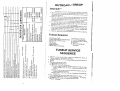
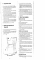
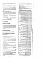

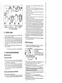

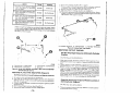
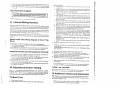
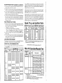
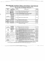
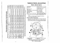
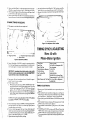
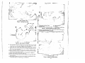
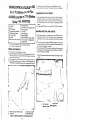

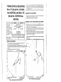
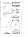


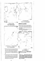

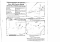
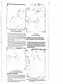
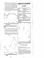


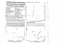

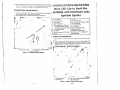


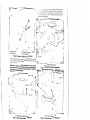

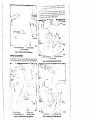


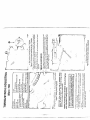

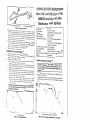


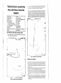

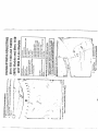


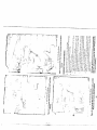

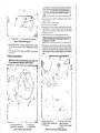
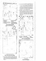
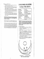
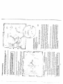
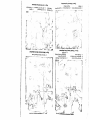
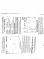
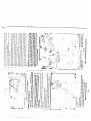
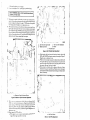
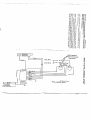

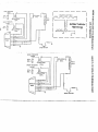
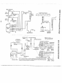
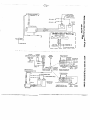


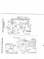
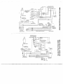
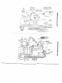
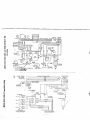


![ISQUES COLUMBIA L. Preetzmann—Àggerhalm ]](http://vs1.manualzilla.com/store/data/006392774_1-0422bcc5d356255aa7f43d6945e506b7-150x150.png)