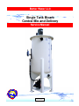
1
Better Water LLC
Single Tank Bicarb
Central Mix and Delivery
Service Manual
rev. Jan 2014
Better Water LLC. All rights reserved.
The content of this manual is the intellectual property of Better Water LLC. It is furnished for the
express use by Better Water LLC, their customers and dealers, for informational use only for operation,
service, and internal training. No part of this manual may be reproduced for distribution, sale, or any
intent other than previously described without the written permission of Better Water LLC. This manual
is subject to change without notice. Better Water LLC assumes no responsibility or liability for any error
or inaccuracies that may appear in this documentation.
Adobe and Acrobat are registered trademarks of Adobe Systems, Inc.
Better Water LLC; 698 Swan Dr; Smyrna, TN 37167; www.betterwater.com
Single Bicarb Tank, Central Mix and Delivery
Service Manual
TABLE OF CONTENTS
Our Company ……………………………………………………………………………………... 01
- Contact Us ……………………………………………………………………………………….. 01
- Technical Phone Support ………………………………………………………………………. 01
- Technical Support Info Online …………………………………………………………………. 01
- Specific Contacts ……………………………………………………………………………….. 02
Introduction ………………………………………………………………………………………… 02
Warnings & Cautions ………………………………………………………………………..…... 03
Models ……………………………………………………………………………………………… 04
- Important Information for Support ……………………………………………………………... 04
- Model Changes Relevant for Support and Replacement Parts ……………………………. 05
Single Bicarb
- Front View ……………………………………………………………………………………….. 07
- Back View ……………………………………………………………………………………….. 08
- Lid and Mounting Hardware …………………………………………………………………… 09
- Mixer Motor Mounts …………………………………………………………………………….. 10
- Mixer Motor, Shaft, & Propellers Diagram ……………………………………………………. 11
- Replacing Propellers, Shaft, and/or Coupling ………………………………………………... 12
- Replacing a Mixer Motor ……………………………………………………………………….. 13
- Return-to-Tank Fitting / Drop-Down Tube …………………………………………………… 14
- Fill Inlet Connections …………………………………………………………………………… 15
- Verifying Float Switch Functionality …………………………………………………………… 16
- Replacing Float Switches ………………………………………………………………………. 17
- Replacing Proximity Sensors ………………………………………………………………….. 18
- Jug Fill Subassembly …………………………………………………………………………… 19
- Replacing the Pump ……………………………………………………………………………. 20
- Pump Mounting Hardware ……………………………………………………………………… 21
- Plumbing Header and Tank Diagram …………………………………………………………. 22
- Plumbing Header ………………………………………………………………………………... 23
- Bicarb Valves Descriptions …………………………………………………………………….. 24
- Bicarb Flow Diagram ………..………………………………………………………………….. 25
Control Box
- Front View ……………………………………………………………………………………….. 26
- Inside Box View, pre January 2005 …………………………………………………………… 27
- Inside Box View, post January 2005 ………………………………………………………….. 28
- Inside Lid View ………………………………………………………………………………….. 29
- Wiring Schematic ……………………………………………………………………………….. 30
Related Replacement Parts ……………………………………………………………………... 31
Limited Warranty Terms and Conditions ……………………………………………………….. 35
Better Water LLC; rev. Jan 2014
Single Bicarb Tank, Central Mix and Delivery
Service Manual
Visit our website to see our complete product line of
water purification products!
www.betterwater.com
Better Water LLC; 698 Swan Dr; Smyrna, TN 37167; www.betterwater.com
Better Water LLC; rev. Jan 2014
Single Bicarb Tank, Central Mix and Delivery
0
Our
Company
Service Manual
Better Water LLC is a leading integrated manufacturer of water treatment
equipment and components for the industrial, commercial and institutional
markets.
Located in Smyrna, Tennessee,
Better Water LLC continues its history
of manufacturing and distribution of
equipment specifically designed for the
renal dialysis market.
Founded in 1971, Better Water LLC has
built a reputation for solving our
customers' toughest problems with high
quality products and unmatched service.
Contact
Us
Technical
Phone
Support
Better Water LLC
698 Swan Dr
Smyrna, TN 37167
Technical Support:
Phone (615) 355-6063, press "1"
Email [email protected]
Phone (615) 355-6063
Fax
(615) 355-6065
Customer Service:
Phone (615) 355-6063, press "3"
Email [email protected]
Support is available regarding all Better Water LLC systems,
24 hours a day, 7 days a week.
• Normal business hours are Monday through Friday from
8:00 am until 3:30 pm, Central Standard Time (excluding holidays)
Call (615) 355-6063, press "1" for Technical Support
Emergency assistance is available after normal business hours (including
holidays) by calling (615) 708-8627.
BEFORE calling for emergency assistance:
• Check the Troubleshooting guide in this manual
•
Check the electrical-power connections, fuses/circuit breakers
(if applicable)
•
Check all valves to ensure each is in the correct position
(if applicable)
Technical
Support
Info
Online
Our website, www.betterwater.com, which is updated
frequently, contains a wealth of technical support information on the
SUPPORT tab and includes:
• Operator and Service Manuals
• Interactive Frequently Asked Questions for Troubleshooting
• Consumables and Accessories Lists
• Technical Service Bulletins
For your convenience there are also online forms for placing Orders
and requesting Returned Goods Authorization. These are Adobe
forms that can be downloaded and either faxed or emailed to us.
Better Water LLC; rev. Jan 2014
Page 1 of 37
Single Bicarb Tank, Central Mix and Delivery
Specific
Contacts
Service Manual
Technical Support
Phone (615) 355-6063, option “1”
Email [email protected]
To Place an Order
(purchase orders)
Fax
(615) 355-6065
Email [email protected]
Phone (615) 355-6063
Customer Service
(returns)
Phone (615) 355-6063, option “2”
Fax
(615) 355-6065
Email [email protected]
Website
www.betterwater.com
Helpful information and forms that can be found on our website:
- Operator & Service Manuals
- Technical Service Bulletins
- Consumables and Replacement Parts List
- Brochures
- Order Form
- Return Goods Authorization Request Form
Introduction
This Service Manual has been developed for the purpose of ordering
factory replacement parts and for Troubleshooting the Single Bicarbs.
This Service Manual is not intended to replace the Operator Manual, but
serve as a supplement to it. Current versions of this Service Manual
and the Operator Manual as well as other helpful information can be
found on our website at www.betterwater.com/support.
It is important to understand that the Better Water Bicarb Unit is a Class
II Medical Device and that non-factory replacement parts could affect
the safety, performance, and warranty of the unit.
This manual includes parts lists, photographs, schematics, and
diagrams to assist you in servicing the unit.
Better Water LLC; rev. Jan 2014
Page 2 of 37
Single Bicarb Tank, Central Mix and Delivery
Service Manual
WARNINGS
1. It is unsafe to operate or service this device without first reading and understanding the entire
Operator and Service Manuals. Keep this manual and other associated documentation for future
reference.
2. Misuse, improper operation, and/or improper monitoring of this system could result in serious
injury, death, or other serious reactions to patients undergoing hemodialysis treatment.
3. Misuse, improper use, or handling of disinfectants and chemical cleaning solutions could result
in serious injury or even death. You must comply with the information contained in the Material
Safety Data Sheet (MSDS) for the chemical being used.
4. To avoid electrical shock hazard, do not operate this device when the covers or panels are
removed.
5.
ELECTROMAGNETIC INTERFERENCE: This device can create and radiate
radio frequency energy and may cause harmful interference if not installed
according to the manufacturer's instructions.
CAUTIONS
1. When used as a medical device, federal law restricts this device to sale by or on the authority
of a physician. Per CFR 801.109 (b)(1).
2. Improper operation of this device could result in a low or no-flow alarm on the dialysis
machines.
3. Misuse or improper operation of this device will void any warranty.
4. Where water is mentioned, unless otherwise noted, it must be AAMI standard quality water.
5. Electrical and plumbing connections must adhere to local statutes and any facility codes.
Connect this device to a proper ground connection in accordance with the National Electrical
Code. Do not remove the ground wire or ground plug. Do not use an extension cord with this
device.
6. Do not remove any Caution, Warning, or any other descriptive labels from the device.
7. Do not operate this device in an explosive environment or in the presence of flammable
materials. Do not use this device to store, mix, or transfer flammable liquids.
8. Movement or vibrations during shipment may cause connections to loosen.
o
9. Do not operate this unit in an environment where temperatures may be below 50 F or above
o
90 F.
10. This device should not be used for purposes outside the device’s stated applications,
specifications, or limitations.
Better Water LLC; rev. Jan 2014
Page 3 of 37
Single Bicarb Tank, Central Mix and Delivery
Service Manual
MODELS
There are two models of the Dual Bicarb unit; the 60 gallon and the 100 gallon. The operation,
service, and replacement parts of these two units are the same with the only difference being the
size of the tanks.
Single 60 Gallon Bicarb Unit
Single 100 Gallon Bicarb Unit
Part#
Part#
EQASSY60BC-1TNK
EQASSY100BC-1TNK
IMPORTANT INFORMATION FOR SUPPORT
Adhered to the front of each Bicarb unit is a label containing important information relating to the
specific Bicarb unit, and details both the Model and Serial Number. Both of these pieces of
information are very important in obtaining support, determining warranty, and properly servicing
the Bicarb unit. Please have this information available if you contact Technical Support.
“13” – Year
“01” - Month
The first four numbers in the serial number denote the year and month the device was
manufactured. In the example above the Single 60 Gallon Bicarb was produced in 2013, in the
month of January.
Better Water LLC; rev. Jan 2014
Page 4 of 37
Single Bicarb Tank, Central Mix and Delivery
Service Manual
MODEL CHANGES RELEVANT for SUPPORT and
REPLACEMENT PARTS
The following is a summary of changes that were made and the time period they were made in
that are relevant to support and determining the correct replacement part numbers. Refer to the
section above concerning the serial number in determining the year and month the device was
manufactured to determine the relevance of these changes to your device.
January 2005 – Control Box Change
The following changes were made to the Control Box:
- Changed from multiple standard relays to a single smart relay and expansion module
- Changed from a contactor/thermal overload to branch circuit protection
* These changes are detailed in the Control Box-Inside View section below
January 2006 – Float Switch Change
A change was made in the float switches in January 2006. Prior to this a shorter, white float
switch was used, and after a longer, black float switch. The shorter, white float switches are no
longer available, so the float switches described below can be ordered as a replacement. If this
is done, a new bulkhead, through which the float switch is installed, is required. This new
bulkhead must have the inside enlarged to accommodate the area required for full motion of the
longer, black float switches.
* See the Single Bicarb-Front View as well as the Replacing Float Switches sections below.
Prior to January 2006
Shorter, White Float Switch
After January 2006
Longer, Black Float Switch
June 2006 – Mixer Motor Mount Change
Prior to June 2006, the mixer motor was mounted on an elongated plastic mount which raised the
motor a few inches above the lid. After June 2006 on, a flat plastic mount was used which
lowered the height of the mixer motor. The mounting hardware also changed to accommodate
the new mount.
* These changes are detailed in the Mixer Motor Mount section below.
Prior to June 2006, Elongated Mount
After June 2006, Flat Mount
Better Water LLC; rev. Jan 2014
Page 5 of 37
Single Bicarb Tank, Central Mix and Delivery
Service Manual
January 2009 – Change from Float Switches to Proximity Sensors
Prior to January 2009, High and Low Level Float Switches were used which are mechanical in
nature. From January 2009 and beyond, electronic sensors were used, and they are not
interchangeable.
* These changes are detailed in the Single Bicarb-Back View as well as the Replacing Float
Switches sections below.
Prior to January 2009
Description
High Level Float Switch, Tank 1
Low Level Float Switch, Tank 1
From January 2009
part#
EQSUBBICBTNK1FL
EQSUBTNK1FL LOW
Description
High Level Sensor, Tank 1
Low Level Sensor, Tank 1
part#
EQSUBTNK1HL
EQSUBTNK1LL
Mid-July 2013 – Ball Valve Change
Units manufactured before mid-July 2013 contained Plast-O-Matic ball valves which were
changed to Asahi ball valves. These valves are not interchangeable. Although their function is
the same, their width and length are slightly different, and the handles are shaped differently.
* These changes are detailed in the Single Bicarb-Front View and Plumbing sections below.
Description
1/2" Ball Valve, Red Handle
3/4" Ball Valve, Red Handle
3/4" Ball Valve, Blue Handle
1” Ball Valve, Blue Handle
1” Ball Valve, Red Handle
Plast-O-Matic Valve
PLVAS800167
PLVAS800169
PLVAS800170
PLVAS800172
PLVAS800174
Asahi Valve
PLVAS800167-A
PLVAS800169-A
PLVAS800170-A
PLVAS800172-A
PLVAS800174-A
Mid-September 2013 – Fuse Change
The control box fuse was changed from a 3 amp to a 2 amp fuse, and moved from fusing the
secondary side of the transformer to fusing the primary side of the transformer. If the fuse
requires changing, it should be replaced with the same size fuse that the control box was built
with which is specified on the face of the box.
ELLFFS00834
Prior to Mid-September 2013
3 amp fuse
ELLFFS00832
After Mid-September 2013
2 amp fuse
Better Water LLC; rev. Jan 2014
Page 6 of 37
Single Bicarb Tank, Central Mix and Delivery
Service Manual
SINGLE BICARB (FRONT VIEW)
Mixer Motor
EQBICB01868
90º 1/2" Poly Elbow
MPT x Hose Barb
PLFIPO00355
Loop Service Valve, 3/4"
Pre-July 2013: PLVAS800170
Post-July 2013: PLVAS800170-A
Jug Fill Valve, 3/4"
Pre-July 2013: PLVAS800170
Post-July 2013: PLVAS800170-A
Service Valve, 1”
Pre-July 2013: PLVAS800172
Post-July 2013: PLVAS800172-A
3/4" 90 Poly Nipple (x2)
PLFIPO00351
Distribution Pump
EQPUIW00453
Drain Valve, 1”
Pre-July 2013: PLVAS800174
Post-July 2013: PLVAS800174-A
Close-Up of Pump
And Drain
Connection
Better Water LLC; rev. Jan 2014
Page 7 of 37
Single Bicarb Tank, Central Mix and Delivery
Service Manual
SINGLE BICARB (BACK VIEW)
High Level Sensor
Pre-2009 (float): EQSUBBICBTNK1FL
2009 (sensor): EQSUBTNK1HL
Flow Switch, 3/4”,
PVC-Clear
PLFSS800443
Low Level Sensor
Pre-2009 (float): EQSUBTNK1FL LOW
2009 (sensor): EQSUBTNK1LL
Clear Suction
Hose, 1FT
PLHOSU01237
Better Water LLC; rev. Jan 2014
Page 8 of 37
Single Bicarb Tank, Central Mix and Delivery
Service Manual
LID & MOUNTING HARDWARE
Mounting Hardware
Kit for 2 Bicarb Lids
<No Part Number>
Top View of Lid
10 holes per lid,
10 of each
1 3/8” x 1/4" Bolt
1/4" Flat Washer
1/4" Locking Washer
1/4" Nut
Underside View of Lid
LID
VOLARA FOAM for Tank Lid
If replacing the Volara Foam (.25” thick x 1.5” width) that helps seal the
lid to the tank, refer to the following:
* 6 ft for 60 gallon Tanks
* 10 ft for 100 gallon Tanks
Volara Foam (.25 x 1.5)
EQBICB01600
Better Water LLC; rev. Jan 2014
Page 9 of 37
Single Bicarb Tank, Central Mix and Delivery
Service Manual
MIXER MOTOR MOUNTS
Mixer Motor
EQBICB01868
Mixer Mount / Spacer
EQBICBMXRMNT
Power Cord
(not shown)
ELPCOO00200
Mounting Hardware
(4 each, not shown)
SS Bolts
HWBOSS01892
SS Lock Washers
HWWASS01913
SS Washers
HWWASS01889
The Mixer Mount / Spacer shown above is included on all Bicarbs produced from June 2006 to
present.
Prior to June 2006, the Mixer Mount shown below was included, but is no longer available.
Mixer Motor
EQBICB01868
Mounting Hardware
(4 each)
Power Cord
(not shown)
ELPCOO00200
SS Bolts
HWBOSS01886
SS Lock Washers
HWWASS01913
SS Washers
HWWASS01889
Mounting Hardware
(4 each)
SS Bolts
HWBOSS01888
SS Washers
HWWASS01889
Mixer Mount
This style no
longer available
SS Nuts (not shown)
HWNUSS01888
Better Water LLC; rev. Jan 2014
Page 10 of 37
Single Bicarb Tank, Central Mix and Delivery
Service Manual
MIXER MOTOR, SHAFT, & PROPELLERS
DIAGRAM
Mixer Motor
EQBICB01868
Power Cord
ELPCOO00200
Spacer
EQBICBMXRMNT
SS Coupling
EQBICB00472
Set Screws (x4)
HWSCSS01920
SS Shaft
EQBICB00471
Poly Pro Props (x3)
EQBICB01923
Set Screws (x3, 1 per prop)
EQBICB01920
Better Water LLC; rev. Jan 2014
Page 11 of 37
Single Bicarb Tank, Central Mix and Delivery
Service Manual
REPLACING PROPELLERS, SHAFT and/or COUPLING
1. Unplug the Bicarb’s Main Power Cord.
2. Remove the Lid bolts and nuts so the lid can be lifted (not removed).
3. Lift the Lid and remove the bolts and nuts holding the Motor to the Motor Mount.
4. Lift the Motor straight up, to expose the Coupling and Shaft above the Lid, then take a pair of
vice-grips and clamp them to the Shaft below the Coupling. This should allow enough support
and access to proceed.
5. Remove the top two Set Screws in the Coupling, then remove the Motor, carefully laying it on
top of the Tank (sideways).
6. The Coupling can remain attached to the Shaft if neither of these two pieces are being
replaced. If replacing the Shaft or Coupling, then remove the bottom two Set Screws in the
Coupling and set it aside.
7. Lift the Lid and take hold of the Shaft before removing the vice-grips, then remove the Shaft
from the Tank.
8. Remove each Propeller from the Shaft by loosening its related Set Screw. It may be
necessary to use a hammer to gently tap down the Propellers to remove them from the Shaft.
9. Replace each Propeller, aligning the Set Screw with the etched groove, then tighten carefully.
NOTE: Over-tightening can cause the threads on the propeller to strip.
10. Lift the Lid, take hold of the Shaft, and reinsert it back into the Tank, and up through the
Mixing Motor Mount. Hold in place with a pair of vice-grips, leaving enough room above the Shaft
to reattach the Coupling.
11. Reattach the Shaft to the Coupling, then the Motor to the Coupling with the Set Screws. Use
Lock-Tight on each of the Set-Screws before tightening because motor vibration will cause the
set screws to back out which can cause damage to the motor and/or shaft assemblies.
12. Remove the vice-grips and allow the Coupling and Shaft to slip down through the Motor
Mount, back into position.
13. Align and reattach the Motor to the Motor Mount using the previously removed bolts and nuts.
14. Realign the Lid and reattach to the Tank using the previously removed bolts and nuts.
15. Plug the Bicarb’s Main Power Cord to an electrical receptacle.
Better Water LLC; rev. Jan 2014
Page 12 of 37
Single Bicarb Tank, Central Mix and Delivery
Service Manual
REPLACING a MIXER MOTOR
1/4" HP Mixer Motor
EQBICB01868
Bicarb Power Cord
ELPCOO00200
1. Unplug the Bicarb’s Main Power Cord
2. Unplug the Motor’s Power Cord from the Control Box.
3. Remove the old Motor’s Wiring Cover and un-wire the Power Cord.
4. Remove the new Motor’s Wiring Cover and re-install/re-wire the Power Cord, consulting the
wiring diagram on the new motor and wire for low voltage. Replace the Wiring Cover when
finished.
* NOTE: Wire for clock-wise rotation to prevent upward water splash.
5. Remove the Lid bolts and nuts so the lid can be lifted (not removed).
6. Lift the Lid and remove the bolts and nuts holding the Motor to the Motor Mount.
7. Lift the Motor straight up, to expose the Coupling and Shaft above the Lid, then take a pair of
vice-grips and clamp them to the Shaft below the Coupling. This should allow enough support
and access to proceed.
8. Remove the top two Set Screws in the Coupling, then remove the Motor, carefully laying it on
top of the Tank (sideways).
9. Attach the new Motor to the Coupling, with the Set Screws. Use Lock-Tight on each of the SetScrews before tightening because motor vibration will cause the set screws to back out which can
cause damage to the motor and/or shaft assemblies.
10. Remove the vice-grips and allow the Coupling and Shaft to slip down through the Motor
Mount, back into position.
11. Align and reattach the Motor to the Motor Mount using the previously removed bolts and nuts.
12. Realign the Lid and reattach to the Tank using the previously removed bolts and nuts.
13. Plug the Motor’s Power Cord into the Control Box.
14. Plug the Bicarb’s Main Power Cord into an electrical receptacle.
Better Water LLC; rev. Jan 2014
Page 13 of 37
Single Bicarb Tank, Central Mix and Delivery
Service Manual
RETURN-to-TANK FITTINGS / DROP-DOWN TUBE
Return-to-Tank
Fitting
(Drop Down Tube
inside tank)
Top View of Lid
Showing Hose, Clamp, & Bulkhead
3/4” Hose Style 5000
Length from tank to header
PLHOST00315
Clamp Lined
Worm-Drive Hose
(x2, one for each end of hose)
PLHOCL002
90º 3/4" Poly Elbow
MPT x Hose Barb
PLFIPO00351
3/4" Poly Bulkhead
PLFIPO00308
3/4" Poly Bulkhead
PLFIPO00308
S8 Male Adapter SxT
PLFIS800098
3/4" Sch 80 Pipe
(32” length)
PLPIS800044
Underside of Lid
Inside Tank View
Showing Bulkhead, Adapter,
and Drop-Down Tube
Better Water LLC; rev. Jan 2014
Page 14 of 37
Single Bicarb Tank, Central Mix and Delivery
Service Manual
FILL INLET CONNECTIONS
1/2” Hose Style 5000
(60 gallon – 19”)
(100 gallon – 25”)
PLHOST00322
90º 1/2" Poly Elbow
MPT x Hose Barb
PLFIPO00355
Clamp Lined
Worm-Drive Hose
PLHOCL001
1/2" Poly Bulkhead
PLFIPO01848
Close-Up of Tank
Showing Hose, Clamp, & Bulkhead
Inside the Tank Connection to the Bulkhead can be one of two configurations both of
which are shipped with the Bicarb in the Accessories Box
90º 1/2" Poly Elbow
MPT x Hose Barb
PLFIPO02070
+
Flow Control, 2.0 GPM
PVC Sch-80
PLFCS802001
- OR -
Better Water LLC; rev. Jan 2014
Page 15 of 37
90º 1/2" Poly Elbow
MPT x Hose Barb
PLFIPO00355
Single Bicarb Tank, Central Mix and Delivery
Service Manual
VERIFYING FLOAT SWITCH FUNCTIONALITY
Float Switches were used on Bicarbs produced prior to January 2009. Bicarbs produced from
January 2009 use the High and Low Level Sensors.
When a Float Switch is suspected of poor functionality or failure, this test should be performed.
This is the same test performed at the Better Water manufacturing facility on returned Float
Switches to verify warranty claims.
1. Obtain a two-lead multi-meter and place in continuity mode.
2. Attach the multi-meter leads to the contacts on the Float Switch wire.
* NOTE: The wire colors are different between the High Level and Low Level Float Switches.
3. Cycle the Float between open and close by raising and lowering the Float.
4. Take note as to whether the multi-meter alarms with the action of the Float reliably.
- The multi-meter should steady alarm when the Float is in the closed position.
* HIGH LEVEL FLOAT SWITCH: alarms on the multi-meter when in the UP position
* LOW LEVEL FLOAT SWITCH: alarms on the multi-meter when in the DOWN position
A failure to steady alarm in the closed position is the determination of a
defective Float Switch.
HIGH LEVEL FLOAT SWITCH
EQSUBBICBTNK1FL
Alarms on the multi-meter when in the UP
position
Attach multi-meter
leads to the Float
Switch wire connection
holes here
LOW LEVEL FLOAT SWITCH
EQSUBTNK1FL LOW
Alarms on the multi-meter when in the
DOWN position
Better Water LLC; rev. Jan 2014
Page 16 of 37
Single Bicarb Tank, Central Mix and Delivery
Service Manual
REPLACING FLOAT SWITCHES
WHITE FLOAT SWITCHES vs. BLACK FLOAT SWITCHES
A change was made in the float switches in January 2006. Prior to this a shorter-white float
switch was used, and after a longer-black float switch. The shorter-white float switches are no
longer available, so the float switches described below can be ordered as a replacement.
Prior to January 2006
Shorter-White Float Switch
After January 2006
Longer-Black Float Switch
Description
High Level Float Switch
Low Level Float Switch
part#
EQSUBBICBTNK1FL
EQSUBTNK1FL LOW
If this is done, a new bulkhead, through which the float switch is installed, is required. This new
bulkhead must have the inside enlarged to accommodate the area required for full motion of the
longer, black float switches. The part number for this bulkhead is PLFIPO00321. If placing an
order for this bulkhead please note on the order “Drill-Out/Enlarge for Old, White, Float
Switch”.
REPLACEMENT INSTRUCTIONS
1. Disconnect the Float Switch’s Wire Connection from the Control Box’s Pigtail Connection.
2. Carefully unscrew the old Float Switch from the Bulkhead.
3. Place the new Float Switch into the bulkhead and carefully thread, taking care not to overtighten it.
4. Correctly orient the Float Switch’s Mechanical Float by turning the Float Switch either clockwise or counter-clockwise.
- HIGH LEVEL FLOAT SWITCH:
The Mechanical Float should be oriented
so that its normal position is sticking
straight out, such that it will pivot at the joint
to bend upward at a 90 degree angle when
floating.
- LOW LEVEL FLOAT SWITCH:
The Mechanical Float should be oriented
so that its normal position is bent at
the pivot at a 90 degree angle hanging
down, such that it will pivot to a straight-out
position when floating.
Normal Position
Floating Position
Normal Position
Floating Position
5. Reconnect the Float Switch’s Wire Connection to its corresponding Control Box’s Pigtail
Connection.
Better Water LLC; rev. Jan 2014
Page 17 of 37
Single Bicarb Tank, Central Mix and Delivery
Service Manual
REPLACING PROXIMITY SENSORS
Proximity Sensors
Prior to January 2009, High and Low Level Float Switches were used which are mechanical in
nature. From January 2009 and beyond, electronic, proximity sensors were used, and they are
not interchangeable.
* If Float Switches are required, see the section above on Replacing Float Switches.
Description
High Level Sensor, Tank 1
Low Level Sensor, Tank 1
part#
EQSUBTNK1HL
EQSUBTNK1LL
REPLACEMENT INSTRUCTIONS
1. Disconnect the Proximity Sensor’s Wire Connection from the Control Box’s Pigtail Connection.
2. Carefully unscrew the old Proximity Sensor from the Bulkhead.
3. Place the new Proximity Sensor into the Bulkhead and carefully thread, taking care not to overtighten it.
4. Reconnect the Proximity Sensor’s Wire Connection to its corresponding Control Box’s Pigtail
Connection.
Better Water LLC; rev. Jan 2014
Page 18 of 37
Single Bicarb Tank, Central Mix and Delivery
Service Manual
JUG FILL SUBASSEMBLY
Item#
Part#
Description
Qty
1
PLPIS800045
1” PVC Sch-80 Pipe, 2 3/16” length
2
2
PLPIS800044
3/4" PVC Sch-80 Pipe, 1 15/16” length
1
3
PLPIS800044
3/4" PVC Sch-80 Pipe, 4 7/16” length
1
4
PLPIS800044
3/4" PVC Sch-80 Pipe, cut to fit, approximately 8”
1
5
PLFIS800167
1” x 4” PVC Sch-80 Nipple, cut in half
1
6
PLFIS800050
1” PVC Sch-80 Tee SxSxS
1
7
PLFIS800062
1” PVC Sch-80 90º Elbow (SxS)
1
8
PLFIS800072
3/4" PVC Sch-80 45 Elbow (SxS)
2
9
PLVAS800170-A
3/4" Blue Ashai Valve
1
10
PLFIPO00351
3/4" MPT x 3/4" HN Polypro Elbow/Nipple
1
11
PLFIS801914
1” S x 1” S x 3/4" S Sch-80 Tee
1
* Reference DWG 3083
REPLACEMENT INSTRUCTIONS IF BROKEN
In the event this assembly gets broken it can be replaced. The parts required will depend upon at
which point the repair can be made, which should be at the pipes (item# 3 or 4), or at the
connection to the bottom of the tank (item# 5).
* A 3/4" Coupling (2 1/8” length) may be required to connect if the pipe
is broken (item# 1, 2, 2A, or 2B). This part number is PLFIS800928.
* Additionally two sections of 1” PVC Sch-80 Pipe may be required which connect to item# 6 Tee
and item# 7 Elbow. This part number is PLPIS800045; 13” for 100-gallon, 9 3/16” for 60-gallon.
Better Water LLC; rev. Jan 2014
Page 19 of 37
Single Bicarb Tank, Central Mix and Delivery
Service Manual
REPLACING the PUMP
1. Unplug the Bicarb’s Main Power Cord.
2. Unplug the cord from the Pump to the Control Box.
3. Disconnect both the 3/4" Hose and the 1” Hose from the pump.
4. Remove the mounting hardware nuts from underneath the Tank Base from the four mounting
holes.
5. Remove the pump, replacing with the new one.
6. Remount the pump to the Tank Base using the mounting hardware. (See Pump Mounting
Hardware diagram below)
7. Reconnect the 3/4" Hose and the 1” Hose to the pump.
8. Plug the Bicarb’s Main Power Cord into an electrical receptacle.
3/4" Worm Drive
Hose Clamp (x2)
PLHOCL002
1" Worm Drive
Hose Clamp (x2)
PLHOCL003
Item#
Part#
Description
Qty
1
EQPUIW00453
MD-100 1/3 HP, 1PH, 115V Pump
1
2
PLFIPO01230
1” x 3/4" Pg Reducer
1
3
PLFIPO00302
1” TxT Coupling
1
4
PLFIPO00351
3/4" Poly 90º Hose Nipple
1
5
PLFIPO00306
1” Poly Hose Nipple
1
6
EQTAFI01860
1” Hose Barb x Union
1
7
PLHOSU01237
1” Suction Hose (100 gal: 20”, 60 gal: 12”)
1
8
PLHOST00315
3/4" Style 5000 Hose (100 gal: 36”, 60 gal: 30”)
1
9
ELHBPL00765
Hubble 2 Pole 3 Wire 15A, 125V, NY PL
1
* Reference DWG 3303
Better Water LLC; rev. Jan 2014
Page 20 of 37
Single Bicarb Tank, Central Mix and Delivery
Service Manual
PUMP MOUNTING HARDWARE
Pump Base
Mounting Hole (x4)
1/4"-20 x 1 1/2" Bolt (x4)
HWBOOO01910
1/4" SS Flat Washer (x4)
HWWASS01888
PUMP BASE
1 3/4" x 3/8” x 3/8”
Rubber Bumper (x4)
HWBUOO00439
TANK BASE
1/4" SS Locking Washer (x4)
HWWAOO01931
1/4" SS Flat Washer (x4)
HWWASS01888
1/4"-20 SS Nut (x4)
HWNUOO01245
Better Water LLC; rev. Jan 2014
Page 21 of 37
Single Bicarb Tank, Central Mix and Delivery
Service Manual
PLUMBING HEADER and TANK DIAGRAM
Return
Hose
Loop
Return
Bicarb Return
Connection
from
Loop
¾” Schedule 80 PVC
Loop
Feed
ReturnPort
(from loop to
tank)
Fill
Hose
Fill Port
(to tank)
Rinse-Down
Hose
Connection
RO Inlet
Water Line
1”
Stainless
Tee
Bicarb Feed
Connection
to
Loop
¾” Schedule
80 PVC
Bicarb Feed Hose from
Bicarb Feed Valve
to
Loop
(valve on back of tank not
shown)
* Reference DWG 3489
Better Water LLC; rev. Jan 2014
Page 22 of 37
Single Bicarb Tank, Central Mix and Delivery
Service Manual
PLUMBING HEADER
Part# EQASSYBCB01859
Loop
Feed
Loop
Return
3/4" PVC Sch80
Union
PLFIS800134
3/4" PVC Sch80
Union
PLFIS800134
Disinfect Valve, 1/2"
Pre-July 2013: PLVAS800167
Post-July 2013: PLVAS800167-A
Sample Port
PLVAS800970
Check Valve, 1/2", SS
PLVASS00846
1/4” Poly Nipple
PLFIPO00304
1/2" Fill Hose
Nipple
PLFIPO00298
Tank Fill Solenoid Valve
PLVAS801819
1/2" Fill Valve
PLVASS00845
Bicarb Return Valve, 3/4"
Pre-July 2013: PLVAS800170
Post-July 2013: PLVAS800170-A
Check Valve, 1/2", SS
PLVASS00846
1/2” Rinse Down-Hose
Fitting
PLFINY00338
3/4" 90 Poly Nipple
PLFIPO00351
3/4" PVC Sch80
Female Adapter
PLFIS800093
Return-To Drain Valve, 3/4"
Pre-July 2013: PLVAS800169
Post-July 2013: PLVAS800169-A
Incoming-Water
Gauge
PLGAOO00653
1/2" Rinse DownHose Valve
PLVASS00845
1” x 1/2" SS
Bushing
Reducer
PLFISS00849
1” SS Tee
PLFISS00870
Better Water LLC; rev. Jan 2014
Page 23 of 37
3/4" 90 Poly
Nipple
PLFIPO00351
Single Bicarb Tank, Central Mix and Delivery
Service Manual
BICARB VALVES LEGEND & DESCRIPTIONS
Fill Valve
This is the main valve used to fill the Tank.
* NOTE: Tank Fill Switch on Control Panel must be in the Tank# 1 position to fill. Once the level
in the tank reaches the High Level Sensor, the Solenoid Valve will close and water flow will
cease.
Loop Return Valve to Tank (B-6)
When the pump is operating and when this valve is in the OPEN position, liquid will return to
Tank.
Return to Drain Valve
When the pump is operating and when this valve is in the OPEN position, liquid will return to
Drain.
Jug Fill Valve
After Bicarb Solution is mixed, this valve is used to take a sample to verify the Bicarb Solution is
mixed properly from Tank. After bicarb solution is verified, this valve is used to fill jugs from Tank
if needed. During the disinfect procedure, this valve can also be used to verify the presence of
disinfectant.
Service Valve
This valve is used to allow liquid to be pumped from Tank through the pump and to the
distribution Loop. When this valve is closed, Tank will be isolated from the pump and distribution
loop.
Drain Valve
This valve is used to drain all liquid from Tank.
Loop Service Valve
This valve must be open to pump any liquid from Tank to the distribution loop. In an emergency
situation, this valve can be closed and all flow to the distribution loop will cease.
Rinse-Down Valve (B-16)
This valve, when open, will allow water to flow through a connected hose to rinse down the inside
of the tanks.
Disinfect Valve (B-21)
This valve is used to rinse the Bicarb distribution loop. When opened, dialysis water will enter the
Bicarb distribution loop. The Return to Drain Valve should be open and this will flush the
distribution loop of all Bicarb solution or disinfect solution.
Loop Return Sample Port
This valve will allow the user to take a sample of the liquid flowing from the distribution loop. This
can be used to verify a Bicarb Solution or to verify the presence or absence of disinfectant
solution.
Tank Fill Solenoid Valve
This valve receives a signal from the High Level Sensors (in Tank) and the Tank Selector Switch
(on the front of the Control Box). If the level of liquid is above the High Level Sensor, this
Solenoid Valve will not open. This Solenoid Valve and the High Level Sensors are deactivated
when the Keyed Disinfect Switch is in the ON position.
Better Water LLC; rev. Jan 2014
Page 24 of 37
Single Bicarb Tank, Central Mix and Delivery
Service Manual
Flow Restrictor
When installed, the Flow Restrictors are installed to only allow 2gpm to flow though the fill lines.
This will prevent the filling process from using too much water from the distribution loop and
possibly causing the dialysis machines to go into a “Low Pressure” alarm condition.
BICARB FLOW DIAGRAM
* Reference DWG 3742
Better Water LLC; rev. Jan 2014
Page 25 of 37
Single Bicarb Tank, Central Mix and Delivery
Service Manual
CONTROL BOX (Front View)
Part# EQASSYBCB01854
Functions & Part Numbers
Pump Indicator Light
This Light will be illuminated when
the distribution Pump is running.
Mixer Control Switch
This switch turns the
mixer motor ON and OFF.
ELPWSW01132
Indicator Light (complete)
ELLPS01894
Replacement Bulb
ELLPLS01896
TANK ALARM Switch
This switch monitors the “Low
Level Alarm”.
ELPWSW01132
FUSE HOLDER / FUSE
This fuse will protect the
entire Control Box.
Fuse Holder
ELOTEL00833
Pre-mid-Sept 2013,
Replacement Fuse
3amp
ELLFFS00834
Post-mid-Sept 2013,
Replacement Fuse
2amp
ELLFFS80032
KEYED DISINFECT
Switch
This switch must be in the
“ON” position when
disinfecting.
This will override the high
level sensors so tanks
can be filled to capacity
for disinfection and
rinsing.
Keyed Disinfect Switch
ELPWSW01135
TANK-FILL Switch
This switch opens
the inlet solenoid
valve to fill the tank.
ELPWSW01132
START Button
After turning Off –
Operate Switch to
OPERATE, Push and
Hold Start Button until
Green Indicator light
stays on.
Start Button
ELPWSW01133
Replacement Key
ELIDRL01130
Replacement Clear
Rubber Boot
ELPWSW01134
Better Water LLC; rev. Jan 2014
Page 26 of 37
OFF – OPERATE Switch
Main Power Switch
ELPWSW01132
Single Bicarb Tank, Central Mix and Delivery
Service Manual
CONTROL BOX (Inside-Box View)
Part# EQASSYBCB01854
Functions & Part Numbers
For Models Produced from January 2005
Mixer Contactor,
5.5 - 8 amp
Provides overload
protection.
Pump Contactor,
2.8 - 4 amp
Provides overload
protection.
ELSICN015
ELSICN013
Smart Relay, 24V
The main controller
that controls all of
the functions of the
Bicarb Unit.
Expansion
Module, 24V
Works in
conjunction
with the Smart
Relay.
ELSIRL012
Transformer
This will convert
the incoming
120vac power and
to 24vac to run
the Smart Relay
ELSIRL014
ELMTTR01380
Receptacles (x3)
These provide a place to plug in
(from the back) the Distribution
Pump and both Mixers
ELHBRE01852
Better Water LLC; rev. Jan 2014
Page 27 of 37
Piezo Alarm
When activated, the
Piezo provides an
audible alarm when
the level in the tank
reaches the Low
Level Sensor
ELSAPZ01097
Single Bicarb Tank, Central Mix and Delivery
Service Manual
CONTROL BOX (Inside-Box View)
Part# EQASSYBCB01854
Functions & Part Numbers
For Models Produced before January 2005
Timer
Controls the length
of time that the
Mixers will run.
Receptacles (x3)
These provide a place to
plug in (from the back)
the Distribution Pump and
both Mixers.
Transformer
This will convert the incoming
120 vac power to 24 vac to
operate the timers and relays that
control all operations of the unit.
ELHBRE01852
ELMTTR01380
Timer Base
ELIDRL01839
Timer
ELIDRL01840
Contactor
Provides
overload
protection for
the Distribution
Pump
ELSICN003
Piezo Alarm
When activated,
the Piezo
provides an
audible alarm
when the level
in the tank
reaches the Low
Level Sensor.
Thermal
Overload
Provides
thermal
protection for
the
Distribution
Pump
Relay
Pump Start.
Relay Base
ELIDRL01142
ELSICN001
Relay
ELIDRL01146
Relay
Mix times.
Relay Base
ELIDRL01143
Relay
ELIDRL01145
Relay (x2)
Controls High and
Level Sensors for
Tank#1 (left) and
#2 (right).
Relay Base
ELIDRL01142
Latching Relay
High Level Shutoff and Disinfect.
ELSAPZ01097
Relay Base
ELIDRL01142
Relay
ELIDRL01146
Relay
ELIDRL01146
NOTE: No picture was available of the inside of the Single Bicarb Control Box built prior to January 2005. The picture shown is that of a Dual
Bicarb Control Box built prior to January 2005. The only difference is the three Receptacles are on the bottom of the box rather than the back.
Better Water LLC; rev. Jan 2014
Page 28 of 37
Single Bicarb Tank, Central Mix and Delivery
Service Manual
CONTROL BOX (Inside of Lid View)
Part# EQASSYBCB01854
Part Numbers
For All Models
Keyed Disinfect
Switch
ELPWSW01135
Tank Fill Switch
ELPWSW01132
Replacement Bulb Tool
ELOTEL02060
Mixer Control Switch
ELPWSW01132
Start Button
ELPWSW01133
Off – Operate Switch
ELPWSW01134
Tank Alarm Switch
ELPWSW01132
Indicator Light
ELLPS01894
Better Water LLC; rev. Jan 2014
Page 29 of 37
Fuse Holder
ELOTEL00833
Single Bicarb Tank, Central Mix and Delivery
Service Manual
CONTROL BOX WIRING SCHEMATIC
Part# EQASSYBCB01854
(printed on inside of Control Box Lid)
Better Water LLC; rev. Jan 2014
Page 30 of 37
Single Bicarb Tank, Central Mix and Delivery
Service Manual
RELATED REPLACEMENT PARTS
DESCRIPTION
PART#
Propeller Shaft
- 316 Stainless Steel
EQBICB00471
Propeller
- Polypropylene
EQBICB01923
Propeller Set Screw
- Stainless Steel
EQBICB01920
Shaft Coupling
- Stainless Steel
EQBICB00472
Coupling Set Screw
- Stainless Steel
HWSCSS01920
Mixer Motor
- 1/4 HP, 115 VAC
EQBICB01868
Mixer-Motor Power Cord
- For Mix/Delivery Bicarbs
EQPCOO00200
MD 100RLT Pump
- 1/3 HP, 1 Phase, 115 VAC
EQPUIW00453
Pictures do not reflect the size of the item in relation to the other pictures
Better Water LLC; rev. Jan 2014
Page 31 of 37
PICTURE
Single Bicarb Tank, Central Mix and Delivery
Service Manual
RELATED REPLACEMENT PARTS
DESCRIPTION
PART#
3/4" Red Handle Valve, Plast-O-Matic
* For models manufactured before mid-July 2013
PLVAS800169
3/4" Red Handle Valve, Asahi
* For models manufactured from mid-July 2013
PLVAS800169-A
3/4” Blue Handle Valve, Plast-O-Matic
* For models manufactured before mid-July 2013
PLVAS800170
3/4” Blue Handle Valve, Asahi
* For models manufactured from mid-July 2013
PLVAS800170-A
1” Blue Handle Valve, Plast-O-Matic
* For models manufactured before mid-July 2013
PLVAS800172
1” Blue Handle Valve, Asahi
* For models manufactured from mid-July 2013
PLVAS800172-A
1” Red Handle Valve, Plast-O-Matic
* For models manufactured before mid-July 2013
PLVAS800174
1” Red Handle Valve, Asahi
* For models manufactured from mid-July 2013
PLVAS800174-A
Pictures do not reflect the size of the item in relation to the other pictures
Better Water LLC; rev. Jan 2014
Page 32 of 37
PICTURE
Single Bicarb Tank, Central Mix and Delivery
Service Manual
RELATED REPLACEMENT PARTS
DESCRIPTION
PART#
High Level Proximity Sensor Subassembly
* For models manufactured from January 2009
EQSUBTNK1HL
Low Level Proximity Sensor Subassembly
* For models manufactured from January 2009
EQSUBTNK1LL
High Level Float Switch:
* For models manufactured before January 2009
EQSUBBICBTNK1FL
Low Level Float Switch
* For models manufactured before January 2009
EQSUBTNK1FL LOW
Concentrate Regulator Calibration Kit
EQASSYCC01
* For calibrating regulators in Floor-Valve-Boxes and Panels
* Blue wand is for bicarbonate; Red wand is for acid
Flow Control, 2.0 GPM PVC Sch-80
PLFCS802001
Check Valve, 1/2", 316 Stainless-Steel
PLVASS00846
Volara Foam for Tank Lid, .25” TK x 1.5” W
EQBICB01600
* 6 ft for 60 gallon Tanks
* 10 ft for 100 gallon Tanks
Pictures do not reflect the size of the item in relation to the other pictures
Better Water LLC; rev. Jan 2014
Page 33 of 37
PICTURE
Single Bicarb Tank, Central Mix and Delivery
Service Manual
RELATED REPLACEMENT PARTS
DESCRIPTION
PART#
Bicarb Remote Alarm Box
EQASSYBICB01709
Bicarb Control Box
EQASSYBCB01854
Fuse, 3 Amp, Little-Fuse
ELLFFS00834
* For models manufactured before mid-September 2013
Fuse, 2 Amp, Little-Fuse
* For models manufactured after mid-September 2013
ELLFFS00832
Fuse Holder
ELOTEL00833
Flow-Switch, 1”, PVC-Clear
PLFSS800443
Pictures do not reflect the size of the item in relation to the other pictures
Better Water LLC; rev. Jan 2014
Page 34 of 37
PICTURE
Single Bicarb Tank, Central Mix and Delivery
Service Manual
LIMITED WARRANTY TERMS and CONDITIONS
a. This limited warranty is given only to the original buyer and covers the equipment delivered
with this limited warranty.
b. The buyer shall be barred from any recovery on this limited warranty or otherwise for damages
due in whole or in part to…
… unreasonable use
… improper operation
… use beyond normal fashion
… failure to follow instructions
… failure to maintain the product in good condition and repair
… or the like.
c. If the buyer discovers or should have discovered a defect in which it is reasonable to conclude
that damage, either personal, property, or economic, may result, the buyer's continued use of the
product shall constitute any assumption of risk by the buyer and a bar to any recovery for breach
of this limited warranty or otherwise.
d. No oral or written representation, information, or advice given by Better Water LLC or any of its
representatives shall create a warranty or in any way increase the scope of this express limited
warranty and shall not form a part of the basis for bargain.
WHAT IS WARRANTED AND FOR HOW LONG?
a. All equipment, excluding ion exchange and filtration media and cartridges, are warranted to be
free from factory defects in materials, and workmanship under normal use for a period of one (1)
year from the date of shipment.
b. It is a condition precedent to recovery on this limited warranty that the buyer strictly comply
with all operating and maintenance guidelines established by Better Water LLC and that the serial
number (if applicable) is intact and legible on the equipment.
c. It is a condition precedent to recovery on this limited warranty for damage to the external finish
of the equipment that the buyer notifies Better Water LLC at the time of the installation that the
finish is damaged.
WHAT IS REMEDY FOR BREACH OF THIS LIMITED WARRANTY or
NEGLIGENCE BY BETTER WATER LLC
a. Buyer's sole and exclusive remedy for any breach of this limited warranty or negligence by
Better Water LLC shall be repair or replacement of the defective part, at the option of Better
Water LLC, provided such defective part is returned to Better Water LLC for inspection.
b. Better Water LLC shall not be obligated to supply an exact replacement of the defective part
and reserves the right to substitute new and improved parts.
c. Better Water LLC shall provide at no cost to buyer, labor to remove and/or replace defective
parts covered by this limited warranty for a period of ninety (90) days from the date of installation
by Better Water LLC of the equipment.
d. After such ninety (90) day period, buyer shall be responsible for any labor or service charge for
the removal and/or replacement of any defective parts.
e. Buyer shall be responsible for all travel expenses and freight charges at all times.
f. Better Water LLC shall have no obligation to repair or replace any defective part if buyer fails to
follow the procedure set forth in “HOW TO OBTAIN A REPLACEMENT PART UNDER LIMITED
WARRANTY”.
IN NO EVENT SHALL THIS LIMITED WARRANTY BE CONSTRUED TO COVER, NOR SHALL
BETTER WATER LLC BE LIABLE TO BUYER AS ANY OTHER PERSON FOR, ANY
CONSEQUENTIAL, INCIDENTIAL, ECONOMIC, DIRECT, INDIRECT, GENERAL OR SPECIAL
DAMAGES, WHICH ARE HEREBY EXPRESSLY DISCLAIMED.
Better Water LLC; rev. Jan 2014
Page 35 of 37
Single Bicarb Tank, Central Mix and Delivery
Service Manual
HOW TO OBTAIN A REPLACEMENT PART UNDER LIMITED WARRANTY
a. Buyer should contact the Customer Service or Technical Support Departments and request a
Return Goods Authorization.
b. Described part(s) will be sent with a purchase order.
c. The returned part(s) will be returned to the factory for limited warranty consideration. If part(s)
are not covered under the limited warranty, part(s) will be considered billable against the
purchase order supplied.
WHAT IS NOT COVERED BY THIS LIMITED WARRANTY:
By way of example and not limitation, this limited warranty does not cover:
• Damage to or replacement of any ion exchange resin of filter media.
• Labor or service charges for the removal and/or replacement of any defective parts after
the ninety (90) day period from the date of installation or sale by Better Water LLC.
• Freight charges and travel expenses.
• Damage from inadequate or defective wiring, improper voltage, improper connections or
electrical service, inadequate or defective plumbing, water supply, or water pressure, or
in violation of applicable building, plumbing or electrical codes, laws, ordinances or
regulations.
• Damage from improper installation or operation, including but not limited to, abuse,
accident, neglect, improper maintenance, freezing and fires, or abnormal use.
• Damage caused by contaminants in Buyer’s water supply, including hardness, chlorine,
chloramines, sulfur, bacterial iron, tannin, algae, oil, organic matter or other unusual
substances, if special equipment has not been installed by Better Water LLC to remove
such contaminants.
• Damage to or caused by filters/membranes or other replacement parts not purchased
from Better Water LLC or damage caused by modification, alteration, repair or service of
the equipment or any of its parts by anyone other than Better Water LLC or its expressly
authorized representatives.
Better Water LLC; rev. Jan 2014
Page 36 of 37
Single Bicarb Tank, Central Mix and Delivery
Better Water LLC; rev. Jan 2014
Page 37 of 37
Service Manual