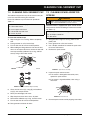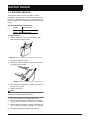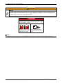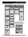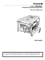
1
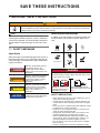
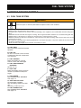
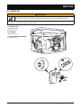
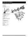
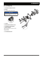
Portable Electrical Generator Service Manual HW7000EH For technical support and parts, contact your Regional Master Parts Distributor toll-free at 1-877-HWTECHS (498-3247) or visit www.honeywellgenerators.com. CONTENTS IMPORTANT SAFETY INSTRUCTIONS SAFETY MESSAGES WARRANTIES ....................................................................... 1-1 ..............................................................................................................................1-1 ............................................................................................................... 2-1 NORTHSHORE POWER SYSTEMS CONSUMER LIMITED WARRANTY ............................................2-1 NORTHSHORE POWER SYSTEMS EVAPORATIVE EMISSIONS CONTROL WARRANTY NORTHSHORE POWER SYSTEMS REPLACEMENT PARTS LIMITED WARRANTY SPECIFICATIONS AND WIRING DIAGRAM SPECIFICATIONS WIRING DIAGRAM ................................................................ 3-1 .................................................................................3-2 ..................................................................................................................................3-3 .............................................................................................................. 4-1 PREPARING FOR SERVICE REQUIRED TOOLS ......................................................................................... 5-1 .................................................................................................................................5-1 TRANSPORTING GENERATOR .............................................................................................................5-1 SERVICE REPAIR TIME ANALYSIS & FLAT RATE SCHEDULE MAINTENANCE CLEANING FUEL SEDIMENT CUP BATTERY SERVICE .............................................................................................7-1 .........................................................................................................7-3 CLEANING SPARK ARRESTOR SCREEN .............................................................................................7-3 ................................................................................................................................7-4 TROUBLESHOOTING ................................................................................................... 8-1 ELECTRICAL DIAGNOSTICS ..................................................................................................................8-2 SERVICE AND DISASSEMBLY FUEL TANK SYSTEM .................................................................................... 9-1 ..............................................................................................................................9-1 EMISSIONS CONTROL SYSTEM ...........................................................................................................9-2 .................................................................................................................................................9-3 ENGINE AND ALTERNATOR ALTERNATOR ..................................................................................................................9-4 .........................................................................................................................................9-5 CONTROL PANEL ...................................................................................................................................9-8 WHEEL, LEG, & HANDLE ASSEMBLY INDEX ............................... 6-1 ............................................................................................................. 7-1 CONSUMER MAINTENANCE SCHEDULE MUFFLER .........................2-4 ....................................................................................................................................3-1 BOLT AND FASTENER TORQUE INFORMATION COMPONENTS ................2-2 ...................................................................................................9-9 .......................................................................................................................... 10-1 Honeywell Portable Electrical Generator Service Manual www.honeywellgenerators.com i THIS PAGE INTENTIONALLY LEFT BLANK ii www.honeywellgenerators.com Honeywell Portable Electrical Generator Service Manual SAVE THESE INSTRUCTIONS 1: IMPORTANT SAFETY INSTRUCTIONS WARNING ANYONE using or servicing this generator must read, understand, and follow all safety and operation instructions provided in the product manual. Failure to closely follow these instructions can result in circumstances leading to death, serious injury, and property damage. Hazard Symbols and Meanings NOTE: Since there are many variations in the circumstances surrounding the installation, operation, service, and maintenance of this generator, we cannot possibly anticipate or provide advice or safety messages to cover every situation. 1.1 SAFETY MESSAGES In addition to the signal words, the following symbols may be used to draw your attention to specific types of hazards. + Explosion Toxic fumes Fire Signal Words Safety messages are provided throughout this manual to help prevent personal injury and equipment damage. All safety messages are introduced by a signal word indicating the hazard level. DANGER Indicates an imminently hazardous situation which, if not avoided, will result in death or serious injury to the operator or to bystanders. WARNING Indicates a potentially hazardous situation which, if not avoided, could result in death or serious injury to the operator or to bystanders. CAUTION Indicates a potentially hazardous situation which, if not avoided, may result in moderate or minor injury to the operator or to bystanders. NOTICE Indicates a situation which, if not avoided, may result in damage to the generator components. Honeywell Portable Electrical Generator Service Manual Chemical burn Hot surface Electrical shock DANGER Using a generator indoors CAN KILL YOU IN MINUTES. Generator exhaust contains carbon monoxide. This is a poison you cannot see or smell. NEVER use inside a home Only use OUTSIDE and far or garage, EVEN IF doors away from windows, doors, and vents. and windows are open. SAFETY PRECAUTIONS • Wear appropriate protective safety equipment, such as safety shoes and safety glasses. • Comply with the warnings in this manual and take special precautions when working around electrical equipment. • Never wear loose or damp clothing that might get caught in equipment or conduct electricity. • Keep service area organized and free of unnecessary clutter to reduce hazard potential. • Keep guards and shields in place on machinery and maintain equipment in good working condition. • Store flammable liquids in approved containers and away from fire, flame, spark, pilot light, switches, arcproducing equipment and other ignition sources. • Use the correct tool for the job and check its condition before starting. • Keep fire extinguishers and safety equipment nearby. www.honeywellgenerators.com 1-1 SAFETY MESSAGES Electric Shock Hazards WARNING Generators produce powerful voltage that can cause death or great physical harm. • NEVER touch bare wires or receptacles. • NEVER use generator with electrical cords that are worn, frayed, bare, or otherwise damaged. • NEVER operate generator in rain or snow, or when the generator is set on wet surface. • Exposed terminals, even on disconnected batteries, can cause electric shock. • NEVER touch both battery terminals with bare hands at the same time. • Remove rings, watches or any other object containing metal when working with battery. If metal comes into contact with battery terminals, electric shock and serious burns can result. • Only use insulated/non-conducting tools when working with or near battery. • NEVER lay tools or other metal objects on top of battery. Fire and Burn Hazards WARNING Fuel and its vapors are extremely flammable and explosive under certain conditions. • Refuel generator only outdoors, in a well-ventilated area. • NEVER enclose the generator in any structure. • Keep generator at least 6 feet (2 meters) away from buildings, other equipment, and combustible materials during operation. • NEVER fill fuel tank while the engine is running. Turn generator OFF and allow to cool before filling with fuel. • NEVER smoke or allow flames or sparks near the generator or where gasoline is stored. • NEVER overfill the fuel tank (there should be no fuel in the filler neck). After refueling, make sure the tank cap is closed properly and securely. • Be careful not to spill fuel when refueling. Spilled fuel or fuel vapor may ignite. If any fuel is spilled, be sure the area is dry before starting the engine. • Avoid repeated or prolonged contact with skin or breathing of vapor. 1-2 www.honeywellgenerators.com WARNING The muffler becomes very hot during operation and remains hot for a while after stopping the engine. • NEVER touch hot surfaces and avoid hot gases. • Let engine cool before storing the generator indoors. WARNING Battery gases are explosive. • NEVER allow open flames, lit cigarettes, sparks, or spark-producing equipment near the battery. Battery electrolyte fluid is comprised of sulfuric acid, which can be very dangerous and cause severe burns. • NEVER allow battery fluid to contact eyes, skin, or clothing. If contact or spillage occurs, immediately flush the area with water. Medical and Life Support Uses WARNING • In case of emergency, call 911 immediately. • NEVER use this product to power life support devices or life support appliances. • NEVER use this product to power medical devices or medical appliances. • Inform your electricity provider immediately if you or anyone in your household depends on electrical equipment to live. • Inform your electrical provider immediately if a loss of power would cause you or anyone in your household to experience a medical emergency. Generator Damage Hazards NOTICE Improper treatment or misuse of generator can cause permanent damage. • NEVER modify generator in any way. • NEVER tamper with governed speed. Generator supplies correct rated frequency and voltage when running at governed speed. • Damage to generator caused by misuse or modification is not covered under warranty. Honeywell Portable Electrical Generator Service Manual 2: WARRANTIES NORTHSHORE POWER SYSTEMS CONSUMER LIMITED WARRANTY Honeywell Portable Generator Effective March 1, 2009 LIMITED WARRANTY Northshore Power Systems, LLC, will repair or replace, free of charge, to the original retail customer, in North America, any parts of the portable generator found by Northshore Power Systems or an authorized service center to be defective in material or workmanship. This limited warranty covers the cost of the replacement parts and labor for defects. Transportation charges are the responsibility of the customer. This limited warranty has time period conditions, operating conditions and disclaimers, limitations of remedies & exclusions as stated below. For warranty service, customer should locate an authorized Honeywell Generator Dealer from www.honeywellgenerators.com or by calling 1-888-HWHELP1 (4943571). LIMITED WARRANTY PERIODS Consumer Use: 3 Years Limited. 1st year, parts and labor. 2nd & 3rd years, parts only. Commercial Use: 1 Year Limited. No warranty for rental use. Commencement and Definitions.The limited warranty period begins on the date of retail purchase by the original purchaser. The limited warranty is not transferable. "Consumer use" is personal use by a retail customer. "Commercial use" is any usage for income producing, business related use. No Extension of Warranty. Repair or replacement pursuant to this limited warranty shall not renew or extend the original warranty period, and any repaired product shall be warranted for the remaining original warranty period only. LIMITATIONS OF REMEDIES. NORTHSHORE POWER SYSTEMS SHALL NOT BE LIABLE TO CUSTOMER, OR TO ANYONE CLAIMING UNDER CUSTOMER, FOR ANY OTHER OBLIGATIONS OR LIABILITIES, INCLUDING, BUT NOT LIMITED TO, OBLIGATIONS OR LIABILITIES ARISING OUT OF BREACH OF CONTRACT OR WARRANTY, NEGLIGENCE OR OTHER TORT OR ANY THEORY OF STRICT LIABILITY, WITH RESPECT TO THE GENERATOR OR NORTHSHORE POWER SYSTEMS'S ACTS OR OMISSIONS OR OTHERWISE. TO THE FULLEST EXTENT PERMITTED BY APPLICABLE LAW, NORTHSHORE POWER SYSTEMS SHALL NOT, IN ANY EVENT, BE LIABLE FOR INCIDENTAL, COMPENSATORY, PUNITIVE, CONSEQUENTIAL, INDIRECT, SPECIAL OR OTHER DAMAGES, INCLUDING BUT NOT LIMITED TO LOSS OF USE, LOSS OF INCOME, LOSS OF TIME, LOSS OF SALES, INJURY TO PERSONAL PROPERTY, OR LIABILITY CUSTOMER INCURS WITH RESPECT TO ANY OTHER PERSON, OR ANY OTHER TYPE OR FORM OF CONSEQUENTIAL DAMAGE OR ECONOMIC LOSS. EXCLUSIONS. In addition to the foregoing disclaimers, limitations and terms, this limited warranty shall not apply to and does not cover accessories, nor does it cover products that are in any way subjected to: (i) improper setup, installation or storage; (ii) lack of proper maintenance and service; (iii) accident, damage, abuse or misuse; (iv) abnormal operating conditions or applications; (v) repair or modification by customer or any third party without prior written consent of Northshore Power Systems; (vi) use under operating conditions or in applications not made known to or contemplated by Northshore Power Systems; or (viii) acts of God. The application of these exclusions will be determined at Northshore Power Systems's sole discretion. DISCLAIMERS, LIMITATIONS OF REMEDIES & EXCLUSIONS This generator is equipped with an engine that is covered exclusively by a separate warranty from the engine manufacturer. Please refer to the engine documentation included with the generator for warranty information related to the engine. This warranty gives you specific legal rights, and you may also have other rights which vary from state to state. REGISTRATION MEDICAL AND LIFE SUPPORT USES. This warranty excludes any use of this product intended to power life support devices, life support appliances, medical devices, or medical appliances. Warranty registration with the Company is required on all products. You may send in the enclosed Product Registration, or register your product on-line at www.honeywellgenerators.com. DISCLAIMER OF OTHER WARRANTIES. TO THE FULLEST EXTENT PERMITTED BY APPLICABLE LAW, THIS LIMITED WARRANTY IS EXCLUSIVE AND EXPRESSLY IN LIEU OF ANY AND ALL OTHER WARRANTIES, INCLUDING, WITHOUT LIMITATION, ANY IMPLIED WARRANTIES OF MERCHANTABILITY OR FITNESS FOR A PARTICULAR PURPOSE OR ANY OTHER IMPLIED WARRANTIES THAT MAY ARISE FROM A COURSE OF DEALING OR USAGE OF TRADE. NORTHSHORE POWER SYSTEMS HEREBY DISCLAIMS AND EXCLUDES ALL OTHER WARRANTIES. To the extent that Northshore Power Systems's products are consumer products under applicable federal or state law with respect to any customer, the duration of any implied warranties (including, but not limited to, implied warranties of merchantability or fitness for a particular purpose) are limited to the shortest duration permitted by applicable law or the limited warranty period provided herein, whichever is longer. Warranty is also available by keeping and showing your original receipt from date of purchase to an authorized Honeywell Generator Dealer. Honeywell Portable Electrical Generator Service Manual GENERATOR SERVICE Do not return your generator to place of purchase for service. For all customer service inquiries, call 1-888-HWHELP1 (494-3571) or visit www.honeywellgenerators.com. Warranty inquiries can be addressed to: Northshore Power Systems, LLC Attention: Service and Warranty Dept. 4425 N Port Washington Road Suite 105 Milwaukee, WI 53212-1082 www.honeywellgenerators.com 2-1 WARRANTIES NORTHSHORE POWER SYSTEMS EVAPORATIVE EMISSIONS CONTROL WARRANTY 1. Any warranted part that is not scheduled for replacement as required maintenance in the written instructions supplied, is warranted for the warranty period stated above. If the part fails during the period of warranty coverage, the part will be repaired or replaced by Northshore Power Systems according to subsection (4) below. Any such part repaired or replaced under warranty will be warranted for the remainder of the period. 2. Any warranted part that is scheduled only for regular inspection in the written instructions supplied is warranted for the warranty period stated above. Any such part repaired or replaced under warranty will be warranted for the remaining warranty period. 3. This evaporative emission control system is warranted for two years. If any evaporative emission-related part on your equipment is defective, the part will be repaired or replaced by Northshore Power Systems. Any warranted part that is scheduled for replacement as required maintenance in the written instructions supplied is warranted for the period of time before the first scheduled replacement date for that part. If the part fails before the first scheduled replacement, the part will be repaired or replaced by Northshore Power Systems according to subsection (4) below. Any such part repaired or replaced under warranty will be warranted for the remainder of the period prior to the first scheduled replacement point for the part. 4. Repair or replacement of any warranted part under the warranty provisions herein must be performed at an authorized Honeywell Service Center. OWNER’S WARRANTY RESPONSIBILITIES 5. Notwithstanding the provisions herein, warranty services or repairs will be provided at an authorized Honeywell Service Center at no charge to the owner. 6. The portable generator owner will not be charged for diagnostic labor that is directly associated with diagnosis of a defective, emission-related warranted part, provided that such diagnostic work is performed at a warranty station. 7. Northshore Power Systems is liable for damages to other engine or equipment components proximately caused by a failure under warranty of any warranted part. 8. Throughout the portable generator warranty period stated above, Northshore Power Systems will maintain a supply of warranted parts sufficient to meet the expected demand for such parts. 9. Any replacement part may be used in the performance of any warranty maintenance or repairs and must be provided without charge to the owner. Such use will not reduce the warranty obligations of Northshore Power Systems. Honeywell Portable Generator WARRANTY STATEMENT The California Air Resources Board and Northshore Power Systems, LLC. are pleased to explain the evaporative emission control system (EECS) warranty on your 2009 portable generator. In California, new portable generators must be designed, built and equipped to meet the State’s stringent anti-smog standards. Northshore Power Systems must warrant the EECS on your portable generator for the period of time listed below provided there has been no abuse, neglect or improper maintenance of your portable generator. Your EECS may include parts such as the carburetor, fuel lines, fuel caps, valves, canisters, filters, vapor hoses, clamps, and other associated emission-related components. Where a warrantable condition exists, Northshore Power Systems will repair your portable generator at no cost to you including diagnosis, parts and labor. MANUFACTURER’S WARRANTY COVERAGE As the portable generator owner, you are responsible for performance of the required maintenance listed in your owner’s manual. Northshore Power Systems recommends that you retain all receipts covering maintenance on your portable generator, but Northshore Power Systems cannot deny warranty solely for the lack of receipts. As the portable generator owner, you should however be aware that Northshore Power Systems may deny you warranty coverage if your portable generator or a part has failed due to abuse, neglect, or improper maintenance or unapproved modifications. You are responsible for presenting your portable generator to Northshore Power Systems’s distribution center or service center as soon as the problem exists. The warranty repairs should be completed in a reasonable amount of time, not to exceed 30 days. If you have a question regarding your warranty coverage, you should contact www.honeywellgenerators.com or by calling 1-888-HWHELP1 (494-3571). GENERAL EVAPORATIVE EMISSIONS WARRANTY COVERAGE Northshore Power Systems warrants to the ultimate purchaser and each subsequent purchaser that the portable generator is: Designed, built and equipped so as to conform with all applicable regulations; and free from defects in materials and workmanship that cause the failure of a warranted part to be identical in all material respects to that part as described in the application for certification. The warranty period begins on the date the portable generator is delivered to an ultimate purchaser or first placed into service. The warranty period is two years. Subject to certain conditions and exclusions as stated below, the warranty on emission-related parts is as follows: 2-2 www.honeywellgenerators.com 10. Add-on or modified parts that are not exempted by the Air Resources Board may not be used. The use of any non-exempted add-on or modified parts by the ultimate purchaser will be grounds for disallowing a warranty claims. Northshore Power Systems will not be liable to warrant failures of warranted parts caused by the use of a non-exempted add-on or modified part. 2.1 WARRANTIES Honeywell Portable Electrical Generator Service Manual WARRANTIES WARRANTED PARTS The repair or replacement of any warranted part otherwise eligible for warranty coverage may be excluded from such warranty coverage if Northshore Power Systems demonstrates that the portable generator has been abused, neglected, or improperly maintained, and that such abuse, neglect, or improper maintenance was the direct cause of the need for repair or replacement of the part. That notwithstanding, any adjustment of a component that has a factory installed, and properly operating, adjustment limiting device is still eligible for warranty coverage. The following emission warranty parts are covered: A. B. C. D. E. F. G. H. I. Fuel Tank Fuel Cap Fuel Line Fuel Line Fittings Clamps Vapor Hoses Carbon Canister Canister Mounting Brackets Carburetor Purge Port Connector QUESTIONS If you have questions regarding your emissions warranty rights and responsibilities, you should contact the Service and Warranty Department at Northshore Power Systems. By phone: 1-414-332-2375 Via web: www.honeywellgenerators.com By US mail: Northshore Power Systems, LLC Attention: Service and Warranty Dept. 4425 N Port Washington Road Suite 105 Milwaukee, WI 53212-1082 Honeywell Portable Electrical Generator Service Manual www.honeywellgenerators.com 2-3 WARRANTIES NORTHSHORE POWER SYSTEMS REPLACEMENT PARTS LIMITED WARRANTY Honeywell Portable Generator For a period of 90 days from the date of sale or installation of a Northshore Power Systems, LLC supplied part, Northshore Power Systems will, at its option and sole discretion, repair or replace the part if it is found to be defective in material or workmanship after inspection by Northshore Power Systems. Any parts which the buyer claims to be defective must be examined by the nearest Authorized Northshore Power Systems Warranty Service Facility. All shipping costs under this limited warranty are to be borne and prepaid by the buyer. DISCLAIMERS, LIMITATIONS OF REMEDIES & EXCLUSIONS This warranty gives you specific legal rights, and you may also have other rights which vary from state to state. DISCLAIMER OF OTHER WARRANTIES. TO THE FULLEST EXTENT PERMITTED BY APPLICABLE LAW, THIS LIMITED WARRANTY IS EXCLUSIVE AND EXPRESSLY IN LIEU OF ANY AND ALL OTHER WARRANTIES, INCLUDING, WITHOUT LIMITATION, ANY IMPLIED WARRANTIES OF MERCHANTABILITY OR FITNESS FOR A PARTICULAR PURPOSE OR ANY OTHER IMPLIED WARRANTIES THAT MAY ARISE FROM A COURSE OF DEALING OR USAGE OF TRADE. NORTHSHORE POWER SYSTEMS HEREBY DISCLAIMS AND EXCLUDES ALL OTHER WARRANTIES. To the extent that Northshore Power Systems's products are consumer products under applicable federal or state law with respect to any customer, the duration of any implied warranties (including, but not limited to, implied warranties of merchantability or fitness for a particular purpose) are limited to the shortest duration permitted by applicable law or the limited warranty period provided herein, whichever is longer. LIMITATIONS OF REMEDIES. NORTHSHORE POWER SYSTEMS SHALL NOT BE LIABLE TO CUSTOMER, OR TO ANYONE CLAIMING UNDER CUSTOMER, FOR ANY OTHER OBLIGATIONS OR LIABILITIES, INCLUDING, BUT NOT LIMITED TO, OBLIGATIONS OR LIABILITIES ARISING OUT OF BREACH OF CONTRACT OR WARRANTY, NEGLIGENCE OR OTHER TORT OR ANY THEORY OF STRICT LIABILITY, WITH RESPECT TO THE GENERATOR OR NORTHSHORE POWER SYSTEMS'S ACTS OR OMISSIONS OR OTHERWISE. TO THE FULLEST EXTENT PERMITTED BY APPLICABLE LAW, NORTHSHORE POWER SYSTEMS SHALL NOT, IN ANY EVENT, BE LIABLE FOR INCIDENTAL, COMPENSATORY, PUNITIVE, CONSEQUENTIAL, INDIRECT, SPECIAL OR OTHER DAMAGES, INCLUDING BUT NOT LIMITED TO LOSS OF USE, LOSS OF INCOME, LOSS OF TIME, LOSS OF SALES, INJURY TO PERSONAL PROPERTY, OR LIABILITY CUSTOMER INCURS WITH RESPECT TO ANY OTHER PERSON, OR ANY OTHER TYPE OR FORM OF CONSEQUENTIAL DAMAGE OR ECONOMIC LOSS. 2-4 www.honeywellgenerators.com EXCLUSIONS. In addition to the foregoing disclaimers, limitations and terms, this limited warranty shall not apply to and does not cover products that are in any way subjected to: (i) improper setup, installation or storage; (ii) lack of proper maintenance and service; (iii) accident, damage, abuse or misuse; (iv) abnormal operating conditions or applications; (v) repair or modification by customer or any third party without prior written consent of Northshore Power Systems; (vi) use under operating conditions or in applications not made known to or contemplated by Northshore Power Systems; or (vii) acts of God. The application of these exclusions will be determined at Northshore Power Systems's sole discretion. NORTHSHORE POWER SYSTEMS PARTS LIMITED WARRANTY CLAIMS PROCEDURES DEFECTIVE NEW PARTS. Parts which are defective from new stock, or immediately upon installation must be filed under limited warranty. The defective part must be returned to Northshore Power Systems’s Service and Warranty Department under the following procedure: 1. Fill out a Warranty Claim Form listing the part number and write “New Defective” in the description. 2. List invoice number that the part was purchased on and/ or provide receipt. NOTE: Freight damaged parts are not valid as warranty claims. FAILURE WITHIN 90 DAYS. Parts which have been installed and have failed within 90 days will be handled by the Northshore Power Systems Service and Warranty Department. A Warranty Claim Form must accompany each part for which coverage under the limited warranty is sought. Claims will not be processed without the model and serial numbers of the unit and the purchase and failure dates for the part. Attach a copy of the original proof-of-purchase (for the part) to the Warranty Claim Form. WARRANTY CLAIMS Warranty claim forms and inquiries can be addressed to: Northshore Power Systems, LLC Attention: Service and Warranty Dept. 4425 N Port Washington Road Suite 105 Milwaukee, WI 53212-1082 Honeywell Portable Electrical Generator Service Manual 3: SPECIFICATIONS AND WIRING DIAGRAM 3.1 SPECIFICATIONS GENERATOR HW7000EH POWER Rated [watts] (+/- 10% under load) 7000 Frequency [hertz] (+/- 5% under load) 60 Voltage [volts] (+/- 5% under load) 120 / 240 OPERATING TEMPERATURE Maximum [F / C] 104q / 40q Minimum [F / C] 14q / -10q ENGINE Speed [rpm] Type Displacement [cc] 3600 OHV 4-Cycle 389 Fuel Tank Capacity [gal / l] 6.5 / 24.6 Engine Oil Capacity [qt / l] 1.2 / 1.1 See Honda Owner’s Manual for Additional Engine Information TABLE 3-2. Honeywell Portable Generator Specifications Honeywell Portable Electrical Generator Service Manual www.honeywellgenerators.com 3-1 BOLT AND FASTENER TORQUE INFORMATION 3.2 BOLT AND FASTENER TORQUE INFORMATION Component-Specific Fastener Fastener Size Torque Values N•m lb. ft. M5 x 12 4 3 M10 x 1.25 x 80 48 35 Axle Bracket Bolts M8 x 16 25 18 Brush Assembly Bolt M5 x 16 2 1.5 Carbon Canister Bracket Bolts M6 x 1.0 x 10 2 1.5 Control Panel Bolts M6 x 1.0 x 15 4 3 Exhaust Pipe Nuts M8 x 1.25 24 17 Fuel Tank Mounting Bolts M6 x 1.0 10 7 Fuel Shut-off Valve Hex Fitting M10 x 1.25 24 17 Muffler to Engine Bolts M8 x 1.25 29 22 M6 x 0.8 x 10 2 1.5 Support Leg to Frame Bolts M8 x 16 25 18 Support Leg to Rubber Stopper Bolts M8 x 25 25 18 Wheel Handle Pivot Bracket Bolts M6 x 40 10 7 Alternator End Cover Bolts Alternator Housing Bolts Spark Arrestor Bolts Engine Torque Values See Honda Owner’s Manual TABLE 3-4. Torque Values 3-2 www.honeywellgenerators.com Honeywell Portable Electrical Generator Service Manual Honeywell Portable Electrical Generator Service Manual Run Stop Start Honda Engine Block Switch Panel Back Green Black/White White Black Black 20A 120V 1 Pole Circuit Breakers 120V AC Hour Meter Electrical Panel Front 30A 240V 2 Pole Circuit Breaker Yellow Brown White Black Yellow X White (Y) Blue (W) Red (X) W G White Brown Yellow/Green (G) Y Connect Y Y G Ground Lug G G W W X X G G Housing W W WIRING DIAGRAM 3.3 WIRING DIAGRAM FIGURE 3-1: HW7000EH Wiring Diagram www.honeywellgenerators.com 3-3 Connector THIS PAGE INTENTIONALLY LEFT BLANK 3-4 www.honeywellgenerators.com Honeywell Portable Electrical Generator Service Manual 4: COMPONENTS K J L A E M I B H N G F C D FIGURE 4-2: Honeywell Portable Electrical Generator Controls and Components A—Power Control Center E—Engine Control Switch Household Outlets Control used to start and stop the engine ignition system. 125VAC 20 Amp Duplex (NEMA 5-20R) outlets to connect 120V appliances to generator for power. Generator Cord 125/250VAC 30 Amp Twist-Lock (NEMA L14-30R) outlet can be used to: • • Power 120V appliances using 4-in-1 power cord (not included). Power 240V appliances using appropriate (NEMA L1430P) power cord (not included). • • • START—Starts generator engine RUN—Prepares engine to start (manual start); Indicates engine is currently running (electric start) STOP—Stops generator engine by inhibiting ignition F—Fuel Shut-off Valve Controls flow of fuel from fuel tank to carburetor. G—Recoil Starter Grip Handle Provides means to manually start engine, if needed. H—Air Cleaner Assembly Breakers Removes dust from engine intake air. Protects circuits from damage caused by overload or short-circuit by stopping the flow of electricity from the generator to the appliance. Master circuit breaker controls power to all outlets. If there is no power at outlets, see TROUBLESHOOTING. I— Choke Control Hour Meter K—Fuel Gage Shows the total unit run time for maintenance purposes. Controls choke valve. Choke control must be moved to ON position when starting a cold engine. J—Fuel Tank Cap Provides a secure seal on fuel tank. Indicates level of fuel currently in fuel tank. Ground Terminal L—Muffler Equipped with Spark Arrester Connects generator to ground wire for grounding protection. Provides outlet for engine exhaust. Prevents sparks and other combustible materials from escaping generator. CAUTION Generator must be grounded to prevent electrical shock from faulty appliances. B—Battery Tray and Battery WARNING Muffler reaches temperatures that can cause serious burns if touched. NEVER touch hot surfaces. M—Spark Plug Cap (Wire) Provides power for electric start feature. Delivers voltage to spark plug. When spark plug needs service, cap must be removed. C—Oil Fill Dipstick N—Carbon Canister Seals off engine oil fill hole and provides indicator for engine oil level. Reduces hydrocarbon emissions. D—Oil Drain Screw Allows engine oil to drain from generator. Honeywell Portable Electrical Generator Service Manual www.honeywellgenerators.com 4-1 THIS PAGE INTENTIONALLY LEFT BLANK 4-2 www.honeywellgenerators.com Honeywell Portable Electrical Generator Service Manual 5: PREPARING FOR SERVICE WARNING ANYONE using or servicing this generator must read, understand, and follow all safety and operation instructions provided in this manual. Failure to closely follow these instructions can result in circumstances leading to death, serious injury, and property damage. 5.1 REQUIRED TOOLS 5.2 TRANSPORTING GENERATOR WARNING A complete set of standard and metric shop tools are required to service the generator. Also needed are: • Hammer • Torque wrench • Volt-ohm meter • Frequency meter • Resistive load - such as a load bank, heaters, light bulbs, etc. When transporting the generator: • Press engine control switch to STOP position. Wood block (for rotor support) • Turn fuel shut-off valve to OFF position. • Keep generator level to prevent fuel spillage. • Hot engine or exhaust system can cause serious burns or fires. Cool generator completely before transporting or storing. NOTICE NEVER drop, strike, or place heavy objects on generator when transporting. Honeywell Portable Electrical Generator Service Manual www.honeywellgenerators.com 5-1 THIS PAGE INTENTIONALLY LEFT BLANK 5-2 www.honeywellgenerators.com Honeywell Portable Electrical Generator Service Manual 6: SERVICE REPAIR TIME ANALYSIS & FLAT RATE SCHEDULE HW7000EH (min.) Operation ELECTRICAL Alternator Complete 120 Battery 30 Brush Assembly 45 Charging Coil Assembly 45 Flash the Field 45 Front Panel Assembly 60 Ignition Coil 50 Meters / Circuit Breakers 45 Oil Shutdown Switch 40 Oil Alert Sender 40 Receptacles / Ports 50 Recoil Assembly 30 Spark Plug 30 Electric Starter 45 Starter Solenoid 35 Voltage Regulator 60 ENGINE Refer to the Honda Shop Manual FUEL & EXHAUST Carbon Canister (with bracket) 45 Carbon Canister Tube 30 Fuel Gauge 30 Fuel Line 30 Fuel Tank 60 Fuel Shut-off Valve 40 Muffler 60 Muffler Gasket 60 Frame 120 Handle Assembly 30 Leg Assembly 30 Wheel Assembly 30 MISC NOTE: Repair times represent generally accepted intervals for conducting a repair. Service centers are always advised to provide feedback during the warranty claim process if additional time may be needed due to unforeseen circumstances. Honeywell Portable Electrical Generator Service Manual www.honeywellgenerators.com 6-1 THIS PAGE INTENTIONALLY LEFT BLANK 6.1 6-2 www.honeywellgenerators.com Honeywell Portable Electrical Generator Service Manual 7: MAINTENANCE 7.1 CONSUMER MAINTENANCE SCHEDULE Periodic maintenance and adjustment are necessary to keep the generator in good operating condition. Perform service and inspection at intervals shown in the Generator Maintenance Schedule (Table 7-1). DANGER WARNING Using a generator indoors CAN KILL YOU IN MINUTES. Generator exhaust contains carbon monoxide. This is a poison you cannot see or smell. Accidental starting of generator can cause severe injury or death. Before performing maintenance, disconnect spark plug cap from spark plug. Also disconnect both starting battery cables. Remove the negative (-) cable first to reduce the risk of arcing. NEVER use inside a home Only use OUTSIDE and far or garage, EVEN IF doors away from windows, doors, and vents. and windows are open. Improper maintenance, or failure to correct a problem before operation, can cause a malfunction in which you can be seriously hurt or killed. Always follow inspection and maintenance recommendations and schedules in this manual. WARNING • Shut off the engine before performing any maintenance. If the engine must be run, be sure the area is well ventilated. NOTICE The maintenance schedule applies to normal operating conditions. If you operate generator under severe conditions, such as sustained high-load or high-temperature, or use it in unusually wet or dusty conditions, consult your servicing dealer for recommendations applicable to your individual needs and use. NOTICE Maintenance, replacement, or repair of the emission control devices and systems may be performed by any non-road engine repair establishment or individual. FREQUENCY* MAINTENANCE TASK Before each use Inspect for/clean debris X Check engine oil level X Change engine oil Check air filter First month or 20 hours of use Every 3 months or 50 hours of use X Every 6 months or 100 hours of use Every year or300 hours of use X X Clean air filter X† Replace air filter Run engine X X‡ Check/adjust spark plug X Replace spark plug X Clean fuel sediment cup X Clean spark arrestor X Clean cylinder cooling fins X** Check/adjust idle speed X** Check/adjust valve clearance X** Clean fuel tank and filter Clean combustion chamber Check fuel tube X Every 500 hours** Every 2 years (replace if necessary)** TABLE 7-1. Generator Maintenance Schedule * Perform at every indicated month or operating hour interval, whichever comes first. † Clean more often when using generator in dusty areas. ‡ It is recommended that the generator is run for 30-60 minutes every three months to ensure the battery remains charged. If the unit is stored for more than a year without running, a battery charger may required to recharge the generator battery. ** These items should be serviced by a Honda service dealer, unless you have the proper tools and are mechanically proficient. Refer to the Honda shop manual for service procedures. Honeywell Portable Electrical Generator Service Manual www.honeywellgenerators.com 7-1 CONSUMER MAINTENANCE SCHEDULE FUEL RECOMMENDATIONS DANGER ENGINE OIL RECOMMENDATIONS NOTICE It is very important to maintain proper level of engine oil to keep engine in good running condition. Fuel and fuel vapors are extremely flammable and explosive under certain conditions. • Refuel generator only outdoors, in a well-ventilated area. • NEVER fill fuel tank while engine is running. Turn generator OFF and allow to cool before filling with fuel. • NEVER smoke or allow flames or sparks near generator or where gasoline is stored. • NEVER overfill fuel tank (no fuel should be in filler neck). After refueling, be sure fuel tank cap is closed properly and securely. • Be careful not to spill fuel when refueling. Spilled fuel or fuel vapor may ignite. If any fuel is spilled, be sure area is dry before starting engine. • Avoid repeated or prolonged contact with skin or breathing of vapor. • Check engine oil level prior to each use. Refill engine oil if oil level is too low. See the Honda Owner’s Manual for instructions on how to properly maintain the engine. Contact an authorized Honda service dealer for engine maintenance and repairs. In some locations, authorized Honeywell service dealers are also Honda service dealers. Contact your local dealer before transporting your generator for service. WARNING ALWAYS stop engine before removing oil fill dipstick. Crankcase pressure can cause hot engine oil to spray out of engine fill hole. Hot engine oil can cause severe burns. NOTICE To avoid damage to the engine, never use stale or contaminated gasoline or oil/gasoline mixture. Avoid getting dirt or water in the fuel tank. Use fresh gasoline with a pump octane rating of 86 or higher. WARNING Gasoline and flammable solvents can cause fire or explosion. NEVER use gasoline or flammable solvent to clean air filter element. • Use only household soap and water to clean air filter element. CAUTION Frequent or prolonged contact with engine oil may cause skin cancer. • Thoroughly wash hands and any areas of skin exposed to used oil with soap and water. 7-2 www.honeywellgenerators.com Honeywell Portable Electrical Generator Service Manual CLEANING FUEL SEDIMENT CUP 7.2 CLEANING FUEL SEDIMENT CUP The sediment cup prevents any dirt or water that may be in the fuel tank from entering the carburetor. 7.3 CLEANING SPARK ARRESTOR SCREEN WARNING Clean fuel sediment cup at the intervals specified in Table 7-1. Muffler reaches temperatures that can cause serious burns if touched. NEVER touch hot surfaces. To clean fuel sediment cup, you will need: Generator muffler is equipped with spark arrestor screen, which must be cleaned according to maintenance schedule (Table 7-1). 10 mm box wrench 22 mm open end wrench Household soap and water To clean spark arrestor screen, you will need: Clean, dry cloth #2 Phillips screwdriver To clean fuel sediment cup: 1. Stop the engine if it is running. Allow to completely cool. Wire brush 1. Stop generator if engine is running. Allow to completely cool. 2. Place generator on a flat, level surface. 2. Place generator on a flat, level surface. 3. Turn the fuel shut-off valve to the OFF position. 3. 4. While holding the fitting above the fuel shut-off valve with a 22 mm open end wrench, remove the fuel sediment cup assembly (sediment cup, o-ring, and fuel screen) using a 10 mm box wrench. Use a Phillips screwdriver to remove the spark arrestor screws and washers. 4. Remove the spark arrestor. C A B FIGURE 7-1: Fuel Sediment Cup Assembly Removal A FIGURE 8: Spark Arrestor Assembly 5. Inspect the spark arrestor screen. If the screen is damaged or excessively worn, replace the spark arrestor. If the screen is in good condition, clean using a wire brush. B C FIGURE 7-2: Fuel Sediment Cup Assembly 5. Clean the fuel screen (A), o-ring (B), and sediment cup (C), with soap and water. 6. Rinse parts thoroughly with water. 7. Wipe the pieces clean with a clean, dry cloth. 8. Reinstall the sediment cup, o-ring, and fuel screen. 9. Turn the fuel shut-off valve to the ON position. FIGURE 9: Clean Screen 6. Reinstall spark arrestor carefully aligning screw holes. 10. Start generator and check for leaks. Honeywell Portable Electrical Generator Service Manual www.honeywellgenerators.com 7-3 BATTERY SERVICE 7.4 BATTERY SERVICE To ensure the battery remains charged, it is recommended that the generator is started every three months. If the unit is stored for more than a year without running, a battery charger may be required to recharge the generator battery. Recommended Battery Replacement: Xtreme XTAX14AHL-BS Yuasa 12N14-3A TABLE 8. Replacement Batteries To replace battery: 1. Loosen and remove nuts on retaining plate; slide retaining plate off support rods. FIGURE 10: Electric Start Battery—Remove Retaining Plate 2. Tip battery slightly forward. 3. Disconnect the black negative (-) battery lead removing the boot, bolt, and nut. FIGURE 12: Electric Start Battery—Lead Connection 4. Disconnect the red positive (+) battery lead removing the boot, bolt, and nut. 5. Remove the battery. NOTE: Dispose of used battery according to guidelines established by your local or state government. 6. Place the new battery in the generator frame. 7. Connect the red positive (+) battery lead to the positive (+) post on the battery; install bolt, nut, and boot. 8. Connect the black negative (-) battery lead to the negative (-) post on the battery; install bolt, nut, and boot. 9. Reinstall retaining plate; tighten bolts and nuts. 7-4 www.honeywellgenerators.com Honeywell Portable Electrical Generator Service Manual 8: TROUBLESHOOTING WARNING NOTE: ANYONE using or servicing this generator must read, understand, and follow all safety and operation instructions provided in the product manual. Failure to closely follow these instructions can result in circumstances leading to death, serious injury, and property damage. DANGER Using a generator indoors CAN KILL YOU IN MINUTES. Generator exhaust contains carbon monoxide. This is a poison you cannot see or smell. NEVER use inside a home Only use OUTSIDE and far or garage, EVEN IF doors away from windows, doors, and vents. and windows are open. NOTE: For all dealer service inquiries, call 1-877-HWTECHS (498-3247) or visit www.honeywellgenerators.com. Honeywell Portable Electrical Generator Service Manual www.honeywellgenerators.com 8-1 ELECTRICAL DIAGNOSTICS 8.1 ELECTRICAL DIAGNOSTICS General Electrical Check Check for Tripped Master Breaker 240V Circuit Check (Out of Spec Voltage) 120V Circuit Check (Out of Spec Voltage) Rated Power Check (Low Power Output) Conduct This Check Only When Directed by General Eletrical Check Conduct This Check Only When Directed by General Eletrical Check Conduct This Check Only When Directed by General Eletrical Check Check Master Breaker Continuity Check Duplex Outlet Breaker Continuity NOTE: At high-altitudes, standard carburetor air-fuel mixture will be rich causing a decrease in engine performance and an increase in fuel consumption. Resolve Overload Problem to Ensure Safe Operation After Electrical Load Resolved Push to Reset Breaker If Out of Range, Replace Breaker If Out of Range, Replace Breaker If Cannot Reset, Replace Breaker Check for Tripped Duplex Circuit Breaker(s) Outlets Above the Breaker Indicate the Excess Load Source Resolve Overload Problem to Ensure Safe Operation After Electrical Load Resolved Wait Several Minutes (for Thermal Breaker to Cool) Push to Reset Breaker If Cannot Reset, Replace Breaker Check Continuity from NEMA L14-30R 240V Receptacle For Each Connection (X, Y, W, G) to Corresponding Alternator Terminal If No Continuity, Check for Tight Connections at the Receptacle & Alternator If Connections Did Not Correct Continuity, Replace Electrical Panel Check Continuity from NEMA 5-20R 120V Duplex Outlet For Each Connection (X or Y, W, G) to NEMA L14-30R 240V Receptacle If No Continuity, Check for Tight Connections at the Receptacle & Alternator If Connections Did Not Correct Continuity, Replace Electrical Panel If Frequency Still Out of Range, see Honda Shop Manual for Engine Troubleshooting Check Voltage Output at NEMA L14-30R 240V Receptacle 246252V G 228252V G X Check Rotor Winding Y (see Manual Section “Alternator Rotor Winding Connection”) 114126V W 114126V If Minimum Rated Power Cannot Be Achieved, see Honda Shop Manual for Engine Troubleshooting Check Main Winding (see Manual Section “Alternator Main Winding Terminal Block”) Check Exciter Winding (see Manual Section “Alternator Exciter Winding Connector”) X Y 123126V s0OWER/UTPUTIS7ITHIN Rated Power Specification Range s6OLTAGEOutput at the NEMA L14-30R 240V Receptacle Drops Below Minimum Start Engine and Run at No Load Adjust Governor, if necessary (see Honda Shop Manual) Start Engine and Add Resistive Loads Until One of the Following Occurs: s&REQUENCY$ROPS"ELOW(Z Check Alternator Brushes for Residue or Defect (see Manual Section “Alternator - Carbon Brushes”) Check Engine Frequency = 62.5 Hz + 0.5 If generator will always operate in altitudes higher than 5000 feet (1500 meters), install smaller carburetor main fuel jet and readjust pilot screw. W 123126V See “Specifications” Page For Rated Power, Voltage, & Frequency Specs Under Load and No Load Conditions Start Engine and Run at No Load If Voltage Out of Range, see “240V Circuit Check” Check Output Voltage = 246-252V Check Voltage Output at NEMA 5-20R 120V Duplex Outlet #1 Adjust Voltage Regulator, if necessary If Voltage Still Out of Range Replace Voltage Regulator W NEMA 5-20R 120V Duplex Outlet #1 NEMA 5-20R 120V Duplex Outlet #2 NEMA 14-30R 240V Receptacle Y G 123126V If Voltage Out of Range, see “120V Circuit Check” Check Voltage Output at NEMA 5-20R 120V Duplex Outlet #2 W X G 123126V If Voltage Out of Range, see “120V Circuit Check” Honeywell Portable Electrical Generator Service Manual www.honeywellgenerators.com 8-2 FUEL TANK SYSTEM 9: SERVICE AND DISASSEMBLY 9.1 FUEL TANK SYSTEM WARNING Fuel and its vapors are extremely flammable and explosive under certain conditions. • Refuel the generator only outdoors, in a well-ventilated area. • NEVER enclose the generator in any structure. • Keep generator at least 6 feet (2 meters) away from buildings, other equipment, and combustible materials during operation. • NEVER fill the fuel tank while the engine is running. Turn the generator OFF and allow it to cool before filling with fuel. • NEVER smoke or allow flames or sparks near the generator or where gasoline is stored. • NEVER overfill the fuel tank (there should be no fuel in the filler neck). After refueling, make sure the tank cap is closed properly and securely. • Be careful not to spill fuel when refueling. Spilled fuel or fuel vapor may ignite. If any fuel is spilled, be sure the area is dry before starting the engine. • Avoid repeated or prolonged contact with skin or breathing of vapor. A—FUEL GAGE After reassembly, check float for proper operation. A B B—FUEL CAP C Be sure air vent hole is clean and free of obstruction. Blow with compressed air if necessary. C—FUEL STRAINER D Before reassembly, be sure fuel strainer is clean and undamaged. E D—FUEL TANK MOUNTING HARDWARE 10 N•m (7 lb. ft.) E—FUEL TANK Before reassembly, clean fuel tank to remove any sediment and dry thoroughly. G F H F—FUEL SCREEN See CLEANING FUEL SEDIMENT CUP, page 7-3. G—FUEL SHUT-OFF VALVE Clear passages if clogged. After reinstalling, check for fuel leakage. Hex fitting - 24 N•m (17 lb. ft.) H—FUEL SEDIMENT CUP See CLEANING FUEL SEDIMENT CUP, page 7-3. Honeywell Portable Electrical Generator Service Manual www.honeywellgenerators.com 9-1 EMISSIONS CONTROL SYSTEM 9.2 EMISSIONS CONTROL SYSTEM A—CARBON CANISTER B—CARBON CANISTER TUBE Secure with hose clamps. C—VAPOR LINE Secure with hose clamps. D—CARBON CANISTER BRACKET 2 N•m (1.5 lb. ft.) C A B D 9-2 www.honeywellgenerators.com Honeywell Portable Electrical Generator Service Manual MUFFLER 9.3 MUFFLER WARNING The muffler becomes very hot during operation and remains hot for a while after stopping the engine. • NEVER touch hot surfaces and avoid hot gases. • Let engine cool before storing the generator indoors. A—EXHAUST PIPE Exhaust pipe nuts: 24 N•m (17 lb. ft.) B—MUFFLER 29 N•m (22 lb. ft.) C—SPARK ARRESTOR SCREEN 2 N•m (1.5 lb. ft.) A B C Honeywell Portable Electrical Generator Service Manual www.honeywellgenerators.com 9-3 ENGINE AND ALTERNATOR 9.4 ENGINE AND ALTERNATOR A—END COVER F 4 N•m (3 lb. ft.) B—ROTOR BOLT E Use oil before replacing the rotor bolt. D C A B C—ALTERNATOR HOUSING BOLTS 48 N•m (35 lb. ft.) D—ALTERNATOR REAR HOUSING AND STATOR H See ALTERNATOR, page 9-5. E—ROTOR See ROTOR, page 9-4. F—ENGINE Contact an authorized Honda service dealer for engine maintenance and repairs. G G—VIBRATION ISOLATOR Insert tabs into holes. Be sure rubber is not chipped, hardened, or worn. Refer to illustration for proper positioning. H—FRAME See WHEEL, LEG, & HANDLE ASSEMBLY, page 9-9. 9-4 www.honeywellgenerators.com Honeywell Portable Electrical Generator Service Manual ALTERNATOR 9.5 ALTERNATOR A—ALTERNATOR ENGINE ADAPTER A B—ROTOR Use appropriate tool to remove rotor. B NOTICE Rotor can become damaged if not properly supported. Place wooden block and rag underneath rotor for support. C E F G D C—STATOR D—MAIN WINDING TERMINAL BLOCK E—ALTERNATOR REAR HOUSING F—BRUSH ASSEMBLY Before removing rotor and stator, remove brush assembly. 2 N•m (1.5 lb. ft.) G—VOLTAGE REGULATOR Honeywell Portable Electrical Generator Service Manual www.honeywellgenerators.com 9-5 ALTERNATOR A—GROUND CABLE B—VOLTAGE REGULATOR A Voltage can be adjusted via potentiometer on rear of voltage regulator (120/240 volts +5%). Replace voltage regulator if adjustment does not correct the problem. C D E B C—EXCITER WINDING CONNECTOR Resistance Specifications*: 1.0-1.5 : Using an ohmmeter, measure resistance between the two blue wires. If specified resistance is not obtained, replace alternator. * The alternator must be at room temperature when resistance is measured. 9-6 www.honeywellgenerators.com Blue Green Blue White Honeywell Portable Electrical Generator Service Manual ALTERNATOR D—ROTOR WIRING Red White BRUSH ASSEMBLY Remove carbon brushes from brush assembly. Inspect brushes for excessive wear or any other defect. Replace if length is less than 5 mm (.2 in.). Using an ohmmeter, verify resistance is less than 0.1 : between the tip of each brush and the terminal. If resistance is out of range, replace brushes. 5-9 mm NOTICE Take care not to damage brushes when removing and installing the brush holder. SLIP RINGS Inspect slip rings for dust, rust, or other damage. If rings are dirty, wipe with clean, lint-free cloth. If rings are rusted or appear damaged, remove rotor and wipe with fine emory cloth. Slip Rings ROTOR WINDING CONNECTION Resistance Specifications*: 45-70 : Remove brushes and measure resistance between slip rings. If specified resistance is not obtained at slip rings, replace alternator. * The alternator must be at room temperature when resistance is measured. E—MAIN WINDING TERMINAL BLOCK Resistance Specifications*: 0.3-0.5 : Using an ohmmeter, measure resistance between the red and white wires. If specified resistance is not obtained, replace alternator. * The alternator must be at room temperature when resistance is measured. Honeywell Portable Electrical Generator Service Manual Red (2 wires) Brown (1 wire) Blue (2 wires) White (2 wires) www.honeywellgenerators.com 9-7 CONTROL PANEL 9.6 CONTROL PANEL A—CONTROL PANEL ASSEMBLY (FRONT) 4 N•m (3 lb. ft.) B—CONTROL PANEL ASSEMBLY (BACK) B C—MAIN CONTROL PANEL (FRONT) • 125VAC 20 Amp Duplex (NEMA 5-20R) • • • • 125/250VAC 30 Amp Twist-Lock (NEMA L14-30R) Master Circuit Breaker (Magnetic) Circuit Breaker (Thermal) Hour Meter C D D—MAIN CONTROL PANEL (BACK) E—SWITCH PLATE (FRONT) F—START / STOP / RUN SWITCH G—SWITCH PLATE (BACK) A ENGINE RUN START E STOP F G 9-8 www.honeywellgenerators.com Honeywell Portable Electrical Generator Service Manual WHEEL, LEG, & HANDLE ASSEMBLY 9.7 WHEEL, LEG, & HANDLE ASSEMBLY A—WHEEL HANDLE PIVOT BRACKET 10 N•m (7 lb. ft.) B—PIN AND CHAIN A C—HANDLE BAR D—RUBBER HANDLE GRIP B E—AXLE 25 N•m (18 lb. ft.) C D F—SUPPORT LEG 25 N•m (18 lb. ft.) G—RUBBER STOPPER 25 N•m (18 lb. ft.) H—WHEEL E NOTICE • Wheel kit is intended to be used specifically with this generator. • NEVER use wheel kit for any other purpose. • NEVER use wheel kit on-road. Honeywell Portable Electrical Generator Service Manual H F G www.honeywellgenerators.com 9-9 THIS PAGE INTENTIONALLY LEFT BLANK 9-10 www.honeywellgenerators.com Honeywell Portable Electrical Generator Service Manual 10: INDEX A P Alternator 9-4,9-5 exciter winding connector 9-6 ground cable 9-6 main winding terminal block 9-7 rotor winding connection 9-7 slip rings 9-7 voltage regulator 9-6 Power Control Center 4-1 ground terminal 4-1 household outlets 4-1 R Rotor 9-5 S B Safety, Important Instructions 1-1 Service and Disassembly 9-1 alternator 9-5 control panel 9-8 emissions control system 9-2 engine and alternator 9-4 fuel tank 9-1 muffler 9-3 preparing for 5-1 wheel, leg, & handle assembly 9-9 Service Repair Time 6-1 Spark Arrestor 7-3,9-3 Specifications 3-1 Battery 7-4 Brush Assembly 9-5 C Components breakers 4-1 choke control 4-1 engine control switch 4-1 fuel shut-off valve 4-1 hour meter 4-1 outlets household 4-1 recoil starter grip 4-1 spark plug cap 4-1 Control Panel 9-8 T Tools, Service 5-1 Torque Information 3-2 Transporting Generator 5-1 Troubleshooting 8-1 E Electrical Diagnostics 8-2 Emissions Control System 9-2 Engine 7-2,9-4 Engine Control Switch 4-1 F V Voltage Regulator 9-5,9-6 W Fuel Gauge 9-1 Fuel Recommendations 7-2 Fuel Sediment Cup 7-3,9-1 Fuel Shut-off Valve 4-1,9-1 Fuel Strainer 9-1 Fuel Tank 9-1 Warranty emissions control 2-2 limited 2-1 replacement parts 2-4 Wheel, Leg, & Handle Assembly 9-9 G Ground Terminal 4-1 H Hour Meter 4-1,9-8 M Maintenance 7-1 battery service 7-4 fuel sediment cup 7-3 schedule 7-1 spark arrestor screen 7-3 Muffler 9-3 O Oil Recommendations 7-2 Outlets 4-1,9-8 household 4-1 Honeywell Portable Electrical Generator Service Manual www.honeywellgenerators.com 10-1 THIS PAGE INTENTIONALLY LEFT BLANK 10-2 www.honeywellgenerators.com Honeywell Portable Electrical Generator Service Manual Northshore Power Systems, LLC 4425 N. Port Washington Rd., Suite 105 Milwaukee, WI 53212-1082 USA HW7000EH - P/N: 102141B August 2009 c 2009 Northshore Power Systems, LLC TEL 1-888-494-3571 The Honeywell Trademark is used under license from Honeywell International Inc. www.honeywellgenerators.com Honeywell International Inc. makes no representation or warranties with respect to this product