1
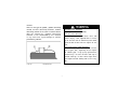
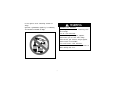
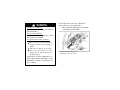
I M P O RTA N T MANUAL INFORMATION
FAILURE TO F O L L O W THE W ARNINGS CONTAINED IN THIS MANUAL CAN
RESULT IN SERIOUS INJURY OR DEATH.
Particularly important information is distinguished in this manual by the following notations:
The Safety Alert Symbol means ATTENTION! BECOME A L E RT!
YOUR SAFETY IS INVO LVED!
Failure to follow warning instructions could result in aevere
injury or death to the machine operator, a bystander or a person
inspecting or repairing the machine.
A CAUTION indicates special precautions that must be taken to
avoid damage to the machine
NOTE:
A NOTE provides key information to make procedures easier or clearer.
Indicates a potential hazard that could result
in serious injury or death.
CONTENTS
1 L O C ATION OF THE W ARNING
AND SPECIFICATION LABELS................ 1
2
SAFETY INFORMATION..........................5
3 DESCRIPTION AND MACHINE
IDENTIFICATION.....................................11
Vehicle identification number ..................... 12
4 CONTROL FUNCTIONS.......................... 13
Mainswitch...............................................13
Indicator and warning lights .......................14
Handlebarswitches......................................17
Throttlelever...............................................20
Speedlimiter................................................21
Frontbrakelever..............................................22
Brake pedal and rear brakeleve....................22
Parkingbrake..............................................23
Driveselectlever..........................................24
Recoilstarter..................................................24
Fueltankcap................................................25
Fuelcock.......................................................26
Starter(choke)................................................27
Seat...............................................................28
Storagebox....................................................29
Frontcarrier..................................................30
Rearcarrier...................................................30
Front shock absorber adjustment.....................30
Rear shock absorber adjustment ........................ 31
5 PRE-OPERATION CHECKS .......................... 33
Frontandrearbrakes.........................................34
Fuel......................................................................36
Engineoil............................................................38
Differentialgearoilreplacement....................110
Axleboots........................................................113
Sparkpluginspection......................................113
Airfilterelementcleaning...............................116
V-beltcoolingductcheckhose.......................119
V-beltcasedrainplug.......................................119
Sparkarrestercleaning...................................120
Carburetoradjustment.....................................121
Idlespeedadjustment.....................................122
Valveclearanceadjustment............................122
Throttleleveradjustment................................123
Frontbrakepadcheck.....................................124
Rearbrakeshoeinspection.............................125
Brakefluidlevelcheck....................................125
Brakefluidreplacement..................................127
Frontbrakeleverfreeplay...............................127
Rear brake pedal and lever adjustment...........128
Adjusting the rear brake light switch .............. 131
Cableinspectionandlubrication.....................132
Lubricating the brake levers and
brakepedal......................................................133
Wheelinstallation............................................134
Battery.............................................................136
Batterymaintenance..........................................137
Fusereplacement..............................................137
Replacingaheadlightbulb................................139
Headlightbeamadjustment..............................142
Tail/brakelightbulbreplacement......................143
Roubleshooting.................................................143
Troubleshootingchart........................................145
9 CLEANING AND STORAGE..........................146
A.Cleaning........................................................146
B.Storage..........................................................148
10 SPECIFICATIONS...........................................150
11 NOISE REGULATION....................................156
LOCATION OF THE W ARNING A N D
SPECIFICATION LABELS
1111
1
1-111111
3
SAFETY INFORMATION
AN AT V IS NOT A TO Y AND CAN BE HAZARDOUS TO OPERATE. An AT V handles differently
from other vehicles including motorcycles and cars. A collision or rollover can occur quickly, even
during routine maneuvers such as turning and riding on hills or over obstacles, if you fail to take
proper precautions.
SEVERE INJURY OR DEATH can result if you do not follow these instructions:
Read this manual and all labels carefully and follow the operating procedures described.
Never operate an AT V without proper training or instruction. Take a Training Course. Beginners should receive training from a certified instructor. Contact an authorized AT V dealer .
Always follow the age recommendation:
- A child under 16 years old should never operate an AT V with engine size greater than 90cc.
Never allow a child under age 16 to operate an AT V without adult supervision, and never allow
continued use of an AT V by a child if he or she does not have the abilities to operate it safely.
Never carry a passenger on an AT V.
Always avoid operating an AT V on any paved surfaces, including sidewalks, driveways, parking lots and streets.
Never operate an AT V on any public street, road or highway, even a dirt or gravel one.
5
Always follow proper procedures for climbing hills as described in this manual. Check the terrain carefully before you start up any hill. Never climb hills with excessively slippery or loose
surfaces. Shift your weight forward. Never open the throttle suddenly. Never go over the top of
a hill at high speed.
Always follow proper procedures for going down hills and for braking on hills as described in
this manual. Check the terrain carefully before you start down any hill. Shift your weight backward. Never go down a hill at high speed. Avoid going down a hill at an angle that would cause
the vehicle to lean sharply to one side. Go straight down the hill where possible.
Always follow proper procedures for crossing the side of a hill as described in this manual.
Avoid hills with excessively slippery or loose surfaces. Shift your weight to the uphill side of the
AT V. Never attempt to turn the AT V around on any hill until you have mastered the turning
technique described in this manual on level ground. Avoid crossing the side of a steep hill if
possible.
Always use proper procedures if you stall or roll backwards when climbing a hill. Maintain a
steady speed when climbing a hill. If you stall or roll backwards, follow the special procedure for
braking described in this manual. Dismount on the uphill side or to a side if pointed straight uphill. Turn the AT V around and remount, following the procedure described in this manual.
Always check for obstacles before operating in a new area. Never attempt to operate over large
obstacles, such as large rocks or fallen trees. Always follow proper procedures when operating
7
When transporting the AT V in another
vehicle, be sure it is kept upright and
that the fuel cock is in the “OFF” position. Otherwise, fuel may leak out of the
carburetor or fuel tank.
W H AT CAN HAPPEN
Gasoline is poisonous and can cause
injuries.
H O W TO AV OID THE HAZARD
If you should swallow some gasoline or
inhale a lot of gasoline vapor, or get
some gasoline in your eyes, see your
If you should swallow some gasoline or
doctor immediately.
If gasoline spills on your skin, wash with
soap and water. If gasoline spills on
your clothing, change your clothes.
POTENTIAL HAZARD
Improper handling of gasoline.
W H AT CAN HAPPEN
Gasoline can catch fire and you could
be burned.
H O W TO AV OID THE HAZARD
Always turn off the engine when refueling.
Do not refuel immediately after the engine has been running and is still very
hot.
Do not spill gasoline on the engine or
exhaust pipe/muffler when refueling.
Never refuel while smoking, or in the vicinity of sparks, open flames, or other
sources of ignition such as the pilot
lights of water heaters and clothes dryers.
9
DESCRIPTION AND MACHIN IDENTIFICATION
1. R ea r sho ck a bso rb er a sse mbly
sp rin g p re loa d a dj us ti ng rin g
1 2. F ro nt sho ck a bso rbe r as sem bl y
sp rin g p re loa d a dj us ti ng rin g
2. Sp ar k arre st er
13. V-b el t co ol in g d uct ch eck h o se
3. St o rag e b ox a nd t oo l kit
14 . O il f il t er ca rt rid ge
4. Sp ar k plu g
15 . Eng in e o il d ip st ic k
5. F ro nt sho ck a bso rbe r as sem bl y 16 . Re ar b rak e le ve r
sp rin g p re loa d a dj us ti ng rin g 17 . Le ft h an dl eb ar s wit ch e s
6. Bra ke pe da l
18 . St art e r (cho ke )
7. V-b e lt case
19 . Dri ve s ele ct le ve r
8. F ue l co ck
20 . Mai n sw it ch
9. Ai r fi lt e r case
21 . Fu e l t an k cap
1 0. F us es
22 . Ri gh t h an d le ba r s wi tc h
11. T ai l/ b rak e li gh t
23. Th ro t tl e le ve r
24 . Fr on t b ra ke le ve r
NOTE:
The machine you have purchased may differ slightly
from those shown in the figures of this manual.
11
CONTROL FUNCTIONS
Indicates a potential hazard that could
result in serious injury or death.
Main switch
Functions of the respective switch positions
are as follows:
ON:
The engine can be started only at this position
and the headlights and taillight come on when
the light switch is on.
OFF:
All electrical circuits are switched off. The key
can be removed in this position.
1. Main switch
13
Oil temperature warning light “ ”
When the oil temperature reaches a specified
level, this light comes on to warn that the engine oil temperature is too hot. If the light
comes on during operation, stop the engine
as soon as it is safe to do so and allow the engine to cool down for about 10 minutes.
The engine may overheat if the A T V is
overloaded. If this happens, reduce
the load to specification.
Restart after making sure that the light
is out. Continuous use while the light
is on may cause damage to the engine.
Left turning indicator light
After open left turning light cntrol,left turning
indicator light is on.
Speed demenstration
Speed demenstration is moving speed of the ATV.
Total course demenstration
Total course demenstration is total moving course of AT V
and can keeps memory.
Right turning indicator light
After open right turning light cntrol,right turning
indicator light is on.
Metric-English system transfer indicator button
Metric-English system transfer indicator button can control
transfer indicator between meric and English in meter.
Metric system demenstration indicator light
Metric system demenstration indicator light is on, it indicates
that vehhicle speed demenstraton is KM/h.
High beam indicator light
High beam indicator light is on, it indicates large headlight source
Small course demenstration
Small course table demenstration only records course number
before closing electrical source.If restart electrical source after
closing it,small course demenstration will record again.
English system demenstration indicator light
English system demenstration indicator light is on, it indicates
that vehhicle speed demenstraton is mph.
15
Handlebar switches
correspondingly, and indicator light”
” on the meter
plate also will light or be out correspondingly.
Do not use the headlights with the engine
turned off for more than thirty minutes.
The battery may discharge to the point
that the starter motor will not operate
properly. If this should happen, remove
the battery and recharge it.
1.High and low beam switch
2.Engine flame out ¡°
¡±
3.Horn switch
4.Electrical starter switch¡±
¡±
5.Turning light switch
¡ñ ¡±
6.light switch¡±
When light switch is pushed to “
” of the first
gear, taillight, front light and meter light will light.
When light switch is pushed to “¡ ”of the second
gear, taillight, front light, large headlight and meter
Turning light switch control
Press turnng light switch left,left front turning light,
left rear turning light and meter left turning indicator
lightarelit.
Press turnng light switch right,right front turning light,
right rear turning light and meter right turning indicatorlightarelit.
Press turning light switch middle,all turning light and
turning indicator light are out.
lightwilllight.
When light switch is pushed to “
” of the second
gear, and press down the button of high & low beam
When change vehicle lines or turn each time on the
move, must form the habit of sending signal. After finishing changing vehicle lines or turning operation,
switch, and high & low beam of large headlight will shift
must close turning light.
17
1. Four-wheel drive switch “2WD/4WD”
2.Emergency light switch ¡°
/ ¡ñ¡±
O n - C o m m a n d f o u r -wheel drive
switch“2WD/4WD”
To change from two-wheel drive (2WD) to
four-wheel drive (4WD), stop the AT V and
set the switch to the 4WD position.
To change from four-wheel drive (4WD) to
two-wheel drive (2WD), stop the AT V and set
the switch to the 2WD position.
19
POTENTIAL HAZARD
Changing from 2WD to 4WD or from
4WD to 2WD while the AT V is moving.
W H AT CAN HAPPEN
The AT V handles differently in 2WD
than in 4WD in some circumstances.
Changing from 2WD to 4WD or from
the AT V to unexpectedly handle differ
ently. This could distract the operator
and increase the risk of losing control
and an accident.
H O W TO AVOID THE HAZARD
Always stop the AT V before changing
from 2WD to 4WD or vice-versa.
Emergency light switch
When AT V happens to be troublesome or
other conditions do, need stop the vehicle
right away to warn other drivers
Speed limiter
The speed limiter keeps the throttle from fully
opening, even when the throttle lever is pushed
to the maximum. Turning in the adjusting screw
limits the maximum engine power available and
decreases the maximum speed of the AT V.
1.Locknut
a. 12 mm (0.47 in)
POTENTIAL HAZARD
Improper adjustment of the speed limiter and throttle.
W H AT CAN HAPPEN
The throttle cable could be damaged.
Improper throttle operation could result.
You could lose control, have an accident or be injured.
H O W TO AV OID THE HAZARD
Do not turn the adjusting screw out
more than 12 mm (0.47 in). Always make
sure the throttle lever free play is adjusted to 3
5 mm (0.12
0.20 in). See page
122.
2. Adjusting screw
21
Parking brake
Use the parking brake when you have to start
the engine or park the machine, especially on
a slope. Apply the rear brake lever and push
down the lock plate to apply the parking
brake. Squeeze the rear brake lever to release the parking brake.
ing the engine. This could of control or a
collision.
The brake could overheat if you ride the AT V
without releasing the parking brake. You could
lose braking perfor-mance which could cause
an accident.
You could also wear out the brakes prematurely.
H O W TO AVOID THE HAZARD
Always set the parking brake before
starting the engine.
Always be sure you have released the
parking brake before you begin to ride.
1.seeerign lock
1. Lock plate
POTENTIAL HAZARD
Improper use of the parking brake.
W H AT CAN HAPPEN
The AT V could start moving unexpect-edly if the
parking brake is not applied before start23
Steering locd
turn the steering bar left,and rnscrew the
lock cover,then insert the key into the
lockstitch,turnitforacompleteroundwith
force, then the steering mechanism can be
locked.
Fuel tank cap
Remove the fuel tank cap by turning it counterclockwise.
POTENTIAL HAZARD
Starting the engine without shifting into
the neutral position.
W H AT CAN HAPPEN
The AT V could start to move unexpectedly, which could cause an accident.
H O W TO AV OID THE HAZARD
Shift the drive select lever into the neutral position and apply the parking brake
before starting the engine.
1. Fuel tank cap
25
Starter (choke) “
”
Starting a cold engine requires a richer air-fuel
mixture. A separate starter circuit supplies this
mixture.
Move in direction a to turn on the starter
(choke).
Move in direction b to turn off the starter
(choke).
Refer to “Starting a cold engine” for proper operation. (See page 43.)
1. Arrow mark pointing to “RES”
1. Starter (choke) “
27
”
Storage box
NOTE:
There is a check hose at the bottom of the
storage box. If any water collects in this hose,
remove the hose, empty it, and then install it.
Maximum load limit: 2 kg (4.4 lb)
To protect from damage, do not put metal
products, like tools or sharply edged products directly in the storage box. If they
must be stored, wrap them in appropriate
cushion material.
1. Storage box check hose
1. Storage box
29
Rear shock absorber adjustment
The spring preload can be adjusted to suit the
rider’s weight and riding conditions.
Adjust the spring preload as follows:
To increase the spring preload, turn the adjusting ring in direction a .
To decrease the spring preload, turn the adjusting ring in direction b .
POTENTIAL HAZARD
Improper shock absorber adjustment.
W H AT CAN HAPPEN
Uneven adjustment can cause poor
handling and loss of stability, which
could lead to an accident.
H O W TO AVOID THE HAZARD
Always adjust the shock absorbers on
the left and right side to the same setting.
1. Spring preload adjusting ring
2. Position indicator
31
PRE-OPERATION CHECKS
Before using this machine, check the following points:
ITEM
ROUTINE
Front brake
Check operation, free play, fluid level and fluid leakage.
Fill with DOT 4 brake fluid if necessary.
Rear brake
Check operation, condition and free play.
Adjust if necessary.
Fuel
Engine oil
111111 PA G E
34-35
123-126
34-35
127-129
124
Check fuel level.
Fill with fuel if necessary.
Check oil level.
Fill with oil if necessary.
36-37
38
102-107
36-37
107-111
Fina l gear oil/
differential gear oil
Check for leakage.
Throttle
Check for proper throttle cable operation.
Wheels and tires
Check tire pressure, wear and damage.
Fittings and fasteners
Check all fittings and fasteners.
Lights and switches
Check for proper operation.
Axle boots
Check for damage.
37
122-123
38-41
132-133
37
37
129-130
138-142
112
33
Brake fluid leakage (front brake)
Check to see if any brake fluid is leaking out of
the hose, joint or brake fluid reservoir of the front
brake. Apply the brake firmly for one minute. If
the lever moves slowly inward, there may be a leak
in the brake system. If there is any leakage, the brake
system should be inspected by a dealer.
POTENTIAL HAZARD
Riding with improperly operating brakes.
W H AT CAN HAPPEN
You could lose braking ability, which could
lead to an accident.
H O W TO AV OID THE HAZARD
Always check the brakes at the start of
every ride. Do not ride the AT V if you find
any problem with the brakes. If a problem
cannot be corrected by the adjustment
procedures provided in this manual, have
a dealer check for the cause.
Brake operation
Test the brakes at slow speed after starting out to
make sure they are working properly.
If the brakes do not provide proper braking performance, inspect the brake pads and shoes for
wear. (See page 123.)
35
Gasohol
There are two types of gasohol; gasohol containing
ethanol and that containing methanol. Gasohol
containing ethanol can be used if ethanol content
does not exceed 10%. Gasohol containing
methanol is not recommended by AT V because
it may cause fuel system damage or vehicle
performance problems.
1. Fuel level
POTENTIAL HAZARD
Improper care when refueling.
W H AT CAN HAPPEN
Fuel can spill, which can cause a fire and
severe injury. Fuel expands when it heats
up.If the fuel tank is overfilled, fuel could
spill out due to heat from the engine or the
sun.
H O W TO AV OID THE HAZARD
Do not overfill the fuel tank. Be careful
not to spill fuel, especially on the engine
or exhaust pipe. W ipe up any spilled fuel
immediately. Be sure the fuel tank cap is
closed securely. Do not refuel right after
the engine has been running and is still very
hot.
2. Fuel tank filler tube
37
Fittings and fasteners
Always check the tightness of chassis fittings and
fasteners before a ride. Take the machine to a AT V
dealer or refer to the Service Manual for correct
tightening torque.
Differential gear oil
Make sure the differential gear oil is at the
specified level. Add oil as necessary. (See pages
110--111 for details.)
Recommended oil:
SAE 80 API GL-4 Hypoid gear oil
Lights
Check the headlights and tail/brake light to make
sure they are in working condition. Repair as
necessary for proper operation.
Throttle lever
Check to see that the throttle lever operates
correctly. It must open smoothly and spring back
to the idle position when released. Have a AT V
dealer repair as necessary for proper operation.
Switches
Check the operation of all switches. Have a AT V
dealer repair as necessary for proper operation.
39
How to measuretire pressure
Use the low-pressure tire gauge.
NOTE:
The low-pressure tire gauge is included as
standard equipment. Make two measurements
of the tire pressure and use the second reading.
Dust or dirt in the gauge could cause the first
reading to be incorrect.
Set pressure with tires cold.
Set tire pressures to the following specifications:
Recommended
pressure
Minimum
Maximum
25kPa
Front (0.25kgf/cm,
3.6psi)
22kPa
(0.22kgf/cm,
3.2psi)
28kPa
(0.28kgf/cm,
4.0psi)
25kPa
(0.25kgf/cm,
3.6psi)
22kPa
(0.22kgf/cm,
3.2psi)
28kPa
(0.28kgf/cm,
4.0psi)
Rear
1. Low-pressure tire gauge
41
Starting a cold engine
O P E R ATION
POTENTIAL HAZARD
Freezing control cables in cold weather.
W H AT CAN HAPPEN
You could be unable to control the AT V,
which could lead to an accident or collision.
H O W TO AV OID THE HAZARD
When riding in cold weather, always make
sure all control cables work smoothly
before you begin riding.
Indicates a potential hazard that could result in
serious injury or death.
POTENTIAL HAZARD
Operating AT V without being familiar with
all controls.
W H AT CAN HAPPEN
Loss of control, which could cause an accident or injury.
H O W TO AVOID THE HAZARD
Read the Owner’s Manual carefully. If there
is a control or function you do notunderstand, ask your AT V dealer.
1. Apply the brake pedal.
2. Turn the fuel cock to “ON”.
3. Turn the main switch to “ON” and the engine stop switch to “
”.
4. Shift the drive select lever into the neutral
position.
43
NOTE:
If the engine fails to start, release the start switch,
See the “Engine break-in” section prior to
operating the engine for the first time.
then push the start switch again. Pause a few
seconds before the next attempt. Each crank
ing should be as short as possible to preserve
battery energy. Do not crank the engine more
than 10 seconds on each attempt.
If the battery is discharged, pull the recoil starter
to start the engine.
Starting a warm engine
To start a warm engine, refer to the “Starting a cold
engine” section. The starter (choke) should not be
used. The throttle should be opened slightly.
7. If the engine is started with the starter (choke) in
position 1 , the starter (choke)should be returned to position 2 to warm up the
engine. If the engine is started with the
starter (choke) in position 2 , keep the starter
(choke) in this position to warm up the
engine.
8. Continue warming up the engine until it idles
smoothly and return the starter (choke) to
position 3 before riding.
W arming up
To get maximum engine life, always warm up the
engine before starting off. Never accelerate hard
with a cold engine! To see whether or not the
engine is warm, check if it responds to the throttle
normally with the starter (choke) turned off
.
45
Shifting: reverse
1. Bring the machine to a complete stop and
return the throttle lever to the closed position.
2. Apply the brake pedal.
3. Shift the gear from neutral to reverse and vice
versa by moving the drive select lever along
the shift guide.
NOTE:
When in reverse, the reverse indicator light should
be on. If the light does not come on, ask a AT V
dealer to inspect.
1. Drive select lever
4. Check behind for people or obstacles, then
release the brake pedal.
5. Open the throttle lever gradually and continue to watch to the rear while backing.
47
Each full throttle acceleration sequence should be
followed with a substantial rest period for the
engine
by cruising at lower r/min so the engine can rid
itself of the temporary build up of heat If any
abnormality is noticed during this period, consult
a AT V dealer.
Engine break-in
There is never a more important period in the life
of your machine than the period between zero
and 20 hours.
For this reason, we ask that you carefully read the
following material. Because the engine is brand
new, you must not put an excessive load on it for
the first several hours of running.
During the first 20 hours, the various parts in the
engine wear and polish themselves to the correct
operating clearances.
During this period, prolonged full throttle operation or any condition which might result in excessive engine heating must be avoided.
However, momentary (2-3 seconds maximum)
full throttle operation under load does not harm
the engine.
0-10 hours:
Avoid continuous operation above half throttle.
Allow a cooling off period of five to ten minutes
after every hour of operation. Vary the speed of
the machine from time to time. Do not operate it
at one set throttle position.
49
Parking on a slope
1. Bring the machine to a stop by applying the
brakes.
2. Stop the engine.
3. W ith the rear brake lever and pedal applied,
apply the parking brake, and then lowly
release the brake pedal.
POTENTIAL HAZARD
Parking on a hill or other incline.
W H AT CAN HAPPEN
The AT V could roll out of control, increas
ing the chance of an accident.
H O W TO AV OID THE HAZARD
Avoid parking on hills or other inclines. If
you must park on an incline, place the
machine transversely across the incline,
apply the parking brake, and block the front
and rear wheels with rocks or other objects.
Do not park the AT V at all on hills that are
so steep you could not walk up them easily.
51
Loading
Cargo or a trailer can change the stability and
handling of an AT V.
You must use common sense and good judgment
when carrying cargo or towing a trailer. Keep the
following points in mind:
Never exceed the weight limits shown. An overloaded AT V can be unstable.
Do not exceed the maximum tongue weight. You
can measure tongue weight with a bathroom
scale. Put the tongue of the loaded trailer on the
scale with the tongue at hitch height. Adjust the
load in the trailer, if necessary, to reduce the
weight on hitch.
If you are carrying cargo and towing a trailer,
include the tongue weight in the maximum
vehicle load limit.
Load cargo on the carrier as close to the center of
the vehicle as possible. Put cargo at the rear of
the front carrier and at the front of the rear
carrier. Center the load from side to side.
Tie down cargo securely to the carriers. Make sure
cargo in the trailer cannot move around. A shifting load can cause an accident.
Make sure the load does not interfere with controls
or your ability to see where you are going.
MAXIMUM LOADING LIMIT
Vehicle loading limit (total weight of cargo,
rider and accessories, and tongue weight):
210 kg (463 lb)
Front carrier: 40 kg (88 lb)
Rear carrier: 80 kg (176 lb)
Storage box: 2.0 kg (4.4 lb)
Trailer hitch:
Pulling load (total weight of trailer and
cargo): 500 kgf (1,102 lbf)
Tongue weight (vertical weight on trailer
hitch point): 15 kgf (33 lbf)
53
Indicates a potential hazard that could
result in serious injury or death.
55
57
RIDE WITH CARE A N D G O O D
JUDGEMENT
H O W TO AVOID THE HAZARD
Beginning and inexperienced operators
should complete the certified training course
offered by AT V.They should then regularly
practice the skills learned in the course and
the operating techniques described in this
Owner’s Manual. For more information
about the training course, contact an authorized AT V dealer.
Get training if you are inexperienced.
Beginners should get training from a certified
instructor.
Become familiar with this AT V at slow speeds
first, even if you are an experienced operator.
Do not attempt to operate at maximum performance until you are totally familiar with the
ATV’s handling and performance characteristics.
Riding your AT V requires skills acquired
through practice over a period of time.
Take the time to learn the basic techniques well
before attempting more difficult maneuvers.
POTENTIAL HAZARD
Operating this AT V without proper instruction.
W H AT CAN HAPPEN
The risk of an accident is greatly increased
if the operator does not know how to operate the AT V properly in different situations
and on different types of terrain.
59
This AT V is designed to carry operator and
cargo only - passengers prohibited.
POTENTIAL HAZARD
Carrying a passenger on this AT V.
W H AT CAN HAPPEN
Greatly reduces your ability to balance
and control this AT V. Could cause an
accident, resulting in harm to you and/
or your passenger.
H O W TO AV OID THE HAZARD
Never carry a passenger. The long seat
is to allow the operator to shift position
as needed during operation. It is not for
carrying passengers.
61
Do not operate after consuming alcohol or
drugs.
Operator’s performance capability is reduced by
the influence of alcohol or drugs.
POTENTIAL HAZARD
Operating this AT V after consuming alcohol or drugs.
W H AT CAN HAPPEN
Could seriously affect your judgment.
Could cause you to react more slowly.
Could affect your balance and perception.
Could result in an accident.
H O W TO AV OID THE HAZARD
Never consume alcohol or drugs before or
while driving this AT V.
c
63
Speed limiter
For riders less experienced with this model, this
model is equipped with a speed limiter in the
throttle lever housing. The speed limiter keeps the
throttle from fully opening, even when the throttle
lever is pushed to the maximum. Turning the
adjusting screw in limits the maximum engine
power available and decreases the maximum
speed of the AT V.Turning the adjusting screw in
decreases top speed and turning it out increases
top speed.
Indicates a potential hazard that could result
in serious injury or death.
Do not operate at speeds too fast for your
skills or the conditions.
POTENTIAL HAZARD
Operating this AT V at speeds too fast
for your skills or the conditions.
W H AT CAN HAPPEN
Increases your chances of losing control of the AT V, which can result in an
accident.
H O W TO AV OID THE HAZARD
Always go at a speed that is proper for
the terrain, visibility and operating conditions, and your experience.
1.Locknut
65
2. Adjusting screw
During operation
Always keep your feet on the footboards during
operation. Otherwise your feet may contact the
rear wheels.
POTENTIAL HAZARD
Removing hands from handlebars or feet
from footboards during operation.
W H AT CAN HAPPEN
Removing even one hand or foot can reduce
your ability to control the AT V or could
cause you to lose your balance and fall off
of the AT V. If you remove a foot from a
footboard, your foot or leg may come into
contact with the rear wheels, which could
injure you or cause an accident.
H O W TO AVOID THE HAZARD
Always keep both hands on the handlebars
and both feet on the footboards of your
AT V your AT V during operation.
67
Modifications
POTENTIAL HAZARD
Operating this AT V with improper modifications.
W H AT CAN HAPPEN
Improper installation of accessories or
modification of this vehicle may cause
changes in handling which in some situations could lead to an accident.
H O W TO AV OID THE HAZARD
Never modify this AT V through improper
installation or use of accessories. All parts
and accessories added to this vehicle
should be genuine AT V or equivalent components designed for use on this AT V and
should be installed and used according to
instructions. If you have questions, consult
an authorized AT V dealer.
69
Know the terrain where you ride. Ride cautiously
in unfamiliar areas. Stay alert for holes, rocks,
or roots in the terrain, and other hidden
hazards which may cause the AT V to upset.
POTENTIAL HAZARD
Failure to use extra care when operating
this AT V on unfamiliar terrain.
W H AT CAN HAPPEN
You can come upon hidden rocks,
bumps, or holes, without enough time to
react. Could result in the AT V overturning or going out of control.
H O W TO AVOID THE HAZARD
Go slowly and be extra careful when operating on unfamiliar terrain. Always be
alert to changing terrain conditions
when operating the AT V.
71
When riding in an area where you might not
easily be seen, such as desert terrain, mount a
caution flag on the AT V. DO NOT use the flag
pole bracket as a trailer hitch.
W H AT CAN HAPPEN
You could be in a collision. You could
be injured.
H O W TO AVOID THE HAZARD
Always mount a caution flag on the AT V
to make you more visible. W atch carefully for other vehicles.
Do not ride in areas posted “no trespassing”. Do
not ride on private property without getting permission.
POTENTIAL HAZARD
Operating in areas where you might not
be seen by other off-road vehicles.
75
TURNING YOUR AT V
To achieve maximum traction while riding off
road, the two rear wheels are mounted solidly
on one axle and turn together at the same speed.
Therefore, unless the wheel on the in side of the
turn is allowed to slip or lose some traction, the
AT V will resist turning. A special turning
technique must be used to allow the AT V to
make turns quickly and easily. It is essential
that this skill be learned first at low speed.
H O W TO AV OID THE HAZARD
Always follow proper procedures for
turning as described in this Owner’s
Manual.
Practice turning at low speeds before attempting to turn at faster speeds. Do not
turn at speeds too fast for your skills or
the conditions.
As you approach a curve, slow down and begin
to turn the handlebars in the desired direction. As
you do so, put your weight on the footboard to
the outside of the turn (opposite your desired
direction) and lean your upper body into the turn.
Use the throttle to maintain an even speed through the turn. This maneuver will let the wheel on
the inside of the turn slip slightly, allowing the
AT V to make the turn properly.
POTENTIAL HAZARD
Turning improperly.
W H AT CAN HAPPEN
AT V could go out of control, causing a
collision or overturn.
77
CLIMBING UPHILL
Use proper riding techniques to avoid vehicle
overturns on hills. Be sure that you can maneuver your AT V well on flat ground before attempting any incline and then practice riding first on
gentle slopes. Try more difficult climbs only
after you have developed your skill. In all cases
avoid inclines with slippery or loose surfaces,
or obstacles that might cause you to
lose control.
H O W TO AV OID THE HAZARD
Never operate the AT V on hills too steep
for the AT V or for your abilities. Practice
on smaller hills before attempting large
hills.
It is important when climbing a hill to make sure
that your weight is transferred forward on the
AT V.This can be accomplished by leaning forward
and, on steeper inclines, standing on the footboards
and leaning forward overthe handlebars.
POTENTIAL HAZARD
Operating on excessively steep hills.
W H AT CAN HAPPEN
The vehicle can overturn more easily on
extremely steep hills than on level surfaces or small hills.
79
If you are climbing a hill and you find that you
have not properly judged your ability to make it
to the top, you should turn the AT V around while
you still have forward motion (provided you
have the room to do so) and go down the hill.
POTENTIAL HAZARD
Improperly crossing hills or turning on
hills.
W H AT CAN HAPPEN
Could cause loss of control or cause the
AT V to overturn.
H O W TO AVOID THE HAZARD
Never attempt to turn the AT V around
on any hill until you have mastered the
turning technique as described in the
Owner’s Manual on level ground. Be
very careful when turning on any hill.
Avoid crossing the side of a steep hill if
possible.
81
If your AT V has stalled or stopped and you believe
you can continue up the hill, restart carefully to
make sure you do not lift the front wheels which
could cause you to lose control. If you are unable
to continue up the hill, dismount the AT V on the
uphill side. Physically turn the AT V around and
then descend the hill.
POTENTIAL HAZARD
Stalling, rolling backwards or improperly
dismounting while climbing a hill.
W H AT CAN HAPPEN
Could result in AT V overturning.
H O W TO AV OID THE HAZARD
Maintain steady speed when climbing a hill.
If you lose all forward speed:
If you start to roll backwards, DO NOT apply
either brake abruptly. If you are in 2WD, apply
only the front brake. When this AT V is in 4WD,
all wheels (front and rear) are interconnected by
the drive train. This means that applying either the
front brake or the rear brake will brake all wheels.
When descending hills, using either brake lever or
the brake pedal will brake the wheels on the downhillside. Avoid sudden application of either the
front or rear brake because the wheels on the uphill side could come off the ground. The AT V
could easily tip over backwards. Apply both the
front and rear brakes gradually, or dismount the
AT V immediately on the uphill side.
Keep weight uphill.
Apply the brakes.
Apply the parking brake after you are
stopped.
83
When this AT V is in 4WD, all wheels (front and
rear) are interconnected by the drive train. This
means that applying either the front brake or the
rear brake will brake all wheels. When descending
hills, using either brake lever or the brake pedal
will brake the wheels on the down hill side. Avoid
sudden application of either the front or rear brake
because the wheels on the uphill side could come
off the ground. Apply both the front and rear
brakes gradually.
RIDING DOWNHILL
When riding your AT V downhill, shift your weight
as far to the rear and uphill side of the AT V as
possible. Move back on the seat and sit with your
arms straight. Engine compression will do most of
the braking for you. For maximum engine compression braking effect, change to 4WD before
beginning to descend the hill. Improper braking may
cause a loss of traction. Use caution while descending a hill with loose or slippery surfaces. Braking ability and traction may be adversely affected
by these surfaces. Improper braking may also cause
a loss of traction.
Whenever possible, ride your AT V straight downhill. Avoid sharp angles which could allow the
AT V to tip or roll over. Carefully choose your
path and ride no faster than you will be able to
react to obstacles which may appear.
85
CROSSING A SLOPE
Traversing a sloping surface on your AT V re
quires you to properly position your weight to
maintain proper balance. Be sure that you have
learned the basic riding skills on flat ground before attempting to cross a sloping surface. Avoid
slopes with slippery surfaces or rough terrain that
may upset your balance.
POTENTIAL HAZARD
Improperly crossing hills or turning on
hills.
W H AT CAN HAPPEN
Could cause loss of control or cause the
AT V to overturn.
H O W TO AV OID THE HAZARD
Never attempt to turn the AT V around on
any hill until you have mastered the turning technique as described in the Owner’s
Manual on level ground. Be very careful
when turning on any hill.
Avoid crossing the side of a steep hill if
possible.
When crossing the side of a hill:
Always follow proper procedures as described in the Owner’s Manual.
Avoid hills with excessively slippery or
loose surfaces. Shift your weight to the
uphill side of the AT V.
As you travel across a slope, lean your body in the
uphill direction. It may be necessary to correct the
steering when riding on loose surfaces by pointing
the front wheels slightly uphill. When riding on
slopes be sure not to make sharp turns either up or
down hill.
If your AT V does begin to tip over, gradually steer
in the downhill direction if there are no obstacles
in your path. As you regain proper balance,
gradually steer again in the direction you wish to
travel.
87
CROSSING T H R O U G H S H A L L O W W AT E R
The AT V can be used to cross slow moving,shallow water of up to a maximum of 35 cm (14
inches) in depth. Before entering the water, choose your path carefully. Enter where there is no
sharp drop off, and avoid rocks or other obstacles
which may be slippery or upset the AT V. Drive
slowly and carefully.
POTENTIAL HAZARD
Operating this AT V through deep or fast
flowing water.
W H AT CAN HAPPEN
Tires may float, causing loss of traction
and loss of control, which could lead to
an accident.
H O W TO AV OID THE HAZARD
Never operate this AT V in fast flowing
water or in water deeper than that specified in your Owner’s Manual.
89
1. V-belt cooling duct check hose (left front side of ATV)
1. Storage box check hose
1. Drive select lever box check hose
1. V-belt case drain plug
91
If the rear wheels of your AT V start to slide sideways, control can usually be regained (if there is
room to do so) by steering in the direction of the
slide. Applying the brakes or accelerating is not
recommended until you have corrected the slide.
SLIDING AND SKIDDING
Care should be used when riding on loose or slippery surfaces since the AT V may slide. If unexpected and uncorrected, sliding could lead to an
accident.
To reduce the tendency for the front wheels to
slide in loose or slippery conditions, positioning
your weight over the front wheels will sometimes
help.
93
W H AT TO DO IF ...
This section is designed to be a reference guide
only. Be sure to read each section on riding techniques completely.
If your AT V starts to slide sideways:
Steer in the direction of the slide if you have
the room. Applying the brakes or accelerating
is not recommended until you have corrected
the slide. (See pages 93--94.)
If your AT V can’t make it up a hill you are trying
to climb:
Turn the AT V around if you still have forward
speed. If not, stop, dismount on the uphill side
of the AT V and physically turn the AT V
around. If the AT V starts to slip backwards,
DO NOT USE THE REAR BRAKE - the AT V
may tip over on top of you. Dismount the AT V
on the uphill side. (See pages 79--84.)
W H AT TO DO ...
If your AT V doesn’t turn when you want it to:
Bring the AT V to a stop and practice the turning
maneuvers again. Be sure you are putting your
weight on the footboard to the outside of the
turn. Position your weight over the front wheels
for better control. (See pages 77--78.)
If your AT V begins to tip while turning:
Lean more into the turn to regain balance. If
necessary, gradually let off the throttle and/or
steer to the outside of the turn. (See pages 77
--78.)
95
POTENTIAL HAZARD
Operating this AT V with improper modifications.
W H AT CAN HAPPEN
Improper installation of accessories or
modification of this vehicle may cause
changes in handling which in some situations could lead to an accident.
H O W TO AVOID THE HAZARD
Never modify this AT V through improper
installation or use of accessories. All parts
and accessories added to this vehicle
should be genuine A T V or equivalent
components designed for use on this AT V
and should be installed and used according
to instructions. If you have questions,
consult an authorized AT V dealer.
1. Owner’s manual
2. Owner’s tool kit
3. Low-pressure tire gauge
NOTE:
If you do not have a torque wrench available
during a service operation requiring one, take
your machine to a AT V dealer to check the
torque settings and adjust them as necessary.
98
EVERY
ITEM
Engine oil
Engine oil filter cartridge
Engine oil strainer*
Final gear oil
Differential gear oil
Front brake*
Rear brake*
Select lever safety system
cable*
V -belt*
Wheel*
Wheel bearing*
Front and rear
suspension*
Steering system*
month
whichever
km
ROUTINE
comes first (mi)
hours
Replace.(Warm engine before draining.)
Replace.
Clean.
Check for oil leakage.
Replace every 12 months.
Check operation/fuid leakage.(See NOTE page 8.
)
Correct if necessary.
Check operation.
Adjust if necessary.
Check operation.
Adjust if necessary.
Check operation.
Check for cracks or damage.
Check balance/damage/runout.
Repair if necessary.
Check bearing assemblies for losseness/damage.
Replace if damaged.
Check operation.
Correct if necessary.
Check operation./Replace if damaged.
Check toe-in./Adjust if necessary.
Drive shaft universal joint*
Lubricate with lithium-soap-based grease.
Axle boots*
Check operation.
Replace if damaged.
100
1
320
(200)
20
INITA L
6
3
12
6
2,400 4,800
1,200 1,200
(750) (1,500) (1,500) (3,000)
150
150
300
75
Panel removal and installation
The panel illustrated needs to be removed to
perform some of the maintenance described in
this chapter.
Refer to this section each time the panel has to
be removed or installed.
Panel A
To remove
Remove the bolt, and then take the panel off.
Toinstall
Place the panel in the original position and install
the bolt.
When installing the panel, be sure not to
pinch the cables or wires.
1. Panel A
1. Panel A
102
2.Bolt
5. Insert the dipstick in the oil filler hole (without screwing it in), and then remove it again
to check the oil level.
NOTE:
The engine oil should be between the minimum
and maximum level marks.
1. Maximum level mark
7. Insert the dipstick into the oil filler hole, and
then tighten the oil filler cap.
2. Minimum level mark
6. If the engine oil is at or below the minimum
level mark, add sufficient oil of the recommended type to raise it to the correct level.
104
1. Oil filter wrench
1. O-ring
NOTE:
An oil filter wrench is available at a nearby AT V
dealer.
5. Apply a light coat of engine oil to the O-ring of
the new oil filter cartridge.
NOTE:
Make sure the O-ring is seated properly.
106
Final gear oil
Final gear oil measurement
1. Place the machine on a level surface.
2. Remove the oil filler bolt, and then check the
oil level in the final gear case.
In order to prevent clutch slipppage (since
the engine oil also lubricates the clutch),
do not mix any chemical additives. Do not
use oils with a diesel specification of “CD
” or oils of a higher quality than specified.
In addition,
do not use oils labeled “ENERGY
CONSERVING II” or higher.
Make sure that no foreign material enters the crankcase.
NOTE:
The oil level should be at the brim of the filler
hole.
9. Start the engine and warm it up for seve-
ral minutes. While warming up, check for
oil leakage. If oil leakage is found, turn
the engine off immediately and check for
the cause.
10. Turn the engine off, and then check the
oil level and correct it if necessary.
1. Final gear oil
2. Final gear oil filler bolt
3. Proper oil level
108
4. Remove the oil filler bolt and the drain bolt to
drain the oil.
Recommended oil:
SAE 80 API GL-4 Hypoid gear oil
Oil quantity:
0.23 L (0.20 Imp qt, 0.24 US qt)
Be sure no foreign material enters the final
gear case.
7. Install the oil filler bolt, and then tighten it to
the specified torque.
8. Check for oil leakage. If oil leakage is found,
check for the cause.
9. Install the final gear case cover bolts, and then
tighten them to the specified torque.
1. Final gear oil drain bolt
5. Install the drain bolt, and then tighten it to the
specified torque.
Tightening torque:
Final gear oil drain bolt:
23 Nm (2.3 m .
kgf, 16 ft .
lbf)
Tightening torque:
Final gear case cover bolt:
16 Nm (1.6 m .kgf, 11 ft.
lbf)
6. Add the recommended final gear oil to the
brim of the filler hole.
110
5. Fill the differential gear case with the specified
amount of the recommended oil.
NOTE:
Do not exceed the specified differential gear
oil quantity when filling. Overfilling will
cause the oil to seep out of the breather
hose during and after riding.
The differential gear oil level cannot bechecked. The differential gear case capacity is
greater than the recommended oil quantity,
therefore the oil level cannot be accurately
checked from the oil filler cap hole.
Be sure no foreign material enters the differential gear case.
6. Install the oil filler bolt, and then tighten it to
the specified torque.
Tightening torque:
Differential gear oil filler bolt:
23 Nm (2.3 m .
kgf, 16 ft .
lbf)
7. Check for oil leakage. If oil leakage is found,
check for the cause.
Recommended oil:
SAE 80 API “GL-4” Hypoid gear oil
Oil quantity:
0.35 L (0.31 Imp qt, 0.37 US qt)
112
2. Use the spark plug wrench in the owner’s
tool kit to remove the spark plug as shown.
Instead, take the AT V toa AT V dealer.You should
periodically remove and inspect the spark plug
because heat and deposits will cause the spark
plug to slowly break down and erode. If elec
trode erosion becomes excessive, or if carbon
and other deposits are excessive, you should replace the spark plug with the specified plug.
Specified spark plug:
DR8EA (NGK)
Installation
1. Measure the electrode gap with a wire thickness gauge and, if necessary, adjust the gap to
specification.
1. Spark plug wrench
Inspection
The spark plug is an important engine component and is easy to inspect. The condition of the
spark plug can indicate the condition of the
engine.
The ideal color on the white insulator around
the center electrode is a medium-to-light tan
color for an AT V that is being ridden normally.
Do not attempt to diagnose such problems
yourself.
Spark plug gap:
0.6
0.7 mm (0.02
114
0.03 in)
Air filter element cleaning
NOTE:
There is a check hose at the bottom of the air
filter case. If dust or water collects in this hose,
empty the hose and clean the air filter element
and air filter case.
1. Holder (¡¡Á4) 2. Air filter case cover
3. Remove the air filter element assembly.
1. Air filter case check hose
1. Remove the seat. (See page 28 for seat
removal and installation procedures.)
2. Remove the air filter case cover by unhooking the holders.
1. Air filter element assembly
116
8. Apply atv foam air filter oil or other quality
foam air filter oil to the air filter element.
NOTE:
The air filter element should be wet but not
dripping.
NOTE:
The air filter element should be cleaned every
20
40 hours. It should be cleaned and lubricated more often if the machine is operated in
extremely dusty areas. Each time the air filter
element maintenance is performed, check the air
inlet to the filter case for obstructions. Check the
air filter case rubber joint to the carburetor and
manifold fittings for an airtight seal. Tighten all
fittings securely to avoid the possibility of unfiltered air entering the engine.
9. Pull the air filter element over its frame, and
then install the lock plate.
10. Install the air filter element assembly.
11. Install the air filter case cover by hooking
the fasteners onto the air filter case.
12. Install the seat.
Never operate the engine with the air filter
element removed. This will allow unfiltered
air to enter, causing rapid engine wear and
possible engine damage. Additionally, operation without the air filter element will affect
carburetor jetting with subsequent poor performance and possible engine overheating.
118
Spark arrester cleaning
Be sure the exhaust pipe and muffler are cool
before cleaning the spark arrester.
1. Remove the bolts.
2. Remove the tailpipe by pulling it out of
the muffler.
1.Spark arrester
4. Insert the tailpipe into the muffler and align
the bolt holes.
5. Install and tighten the bolts.
1. Bolt (¡3)
¡Á 2. Tailpipe
3. Tap the tailpipe lightly, and then use a
wire brush to remove any carbon deposits from the spark arrester portion of the
tailpipe.
120
Idle speed adjustment
NOTE:
A diagnostic tachometer must be used for this
procedure.
1. Start the engine and warm it up for a few
minutes at approximately 1,000 to 2,000
r/min. Occasionally rev the engine to 4,000
to 5,000 r/min. The engine is warm when it
quickly responds to the throttle.
2. Connect the tachometer to the spark plug
lead, and then set the idle to the specified
idling speed by adjusting the throttle stop
screw. Turn the screw in direction a to
increase the engine speed, and in direction
b to decrease the engine speed.
1. Throttle stop screw
Valve clearance adjustment
The correct valve clearance changes with use,
resulting in improper fuel/air supply or engine
noise. To prevent this, the valve clearance must
be adjusted regularly. This adjustment however,
should be left to a professional AT V service
technician.
Specified idle speed:
1,450 1,550 r/min
122
Front brake pad check
Check the brake pads for damage and wear. If a
brake pad thickness is less than 1 mm (0.04 in),
have a AT V dealer replace the pads as a set.
a. Throttle lever free play
a. Brake pad thickness
NOTE:
The wheels need to be removed to check the
brake pads. (See pages 134--135 for removal
and installation procedures.)
124
Observe these precautions:
Brake fluid may deteriorate painted surfaces or
plastic parts. Always clean up spilled fluid
immediately.
Have a dealer check the cause if the brake fluid
level goes down.
When checking the brake fluid level, make sure
the top of the brake fluid reservoir is level.
Use only the designated quality brake fluid,
otherwise, the rubber seals may deteriorate,
causing leakage and poor brake performance.
Recommended brake fluid: DOT 4
Refill with the same type of brake fluid. Mixing
fluids may result in a harmful chemical
reaction and lead to poor brake performance.
Be careful that water does not enter the brake
fluid reservoir when refilling. W ater will significantly lower the boiling point of the fluid
and may result in vapor lock.
126
Rear brake pedal and lever adjustment
Brake pedal free play adjustment
1. Fully loosen the adjusting nut on the brake
lever cable at the rear wheel.
POTENTIAL HAZARD
Operating with improperly serviced or
adjusted brakes.
W H AT CAN HAPPEN
You could lose braking ability, which
could lead to an accident.
H O W TO AVOID THE HAZARD
After servicing:
Make sure the brakes operate
smoothly and that the free play is
correct.
Make sure the brakes do not drag.
Make sure the brakes are not
spongy.All air must be bled fro m
the brake system.
1. Adjusting nut (brake pedal cable)
2. Adjusting nut (brake lever cable)
Replacement of brake components requires professional knowledge. These
procedures should be performed by
AT V a dealer.
128
2. Turn in the adjusting nut on brake cable to
provide a gap of 0 1 mm (0 0.04 in) between the brake camshaft lever and the pin.
3. Turn the adjusting bolt at the brake lever until
the free play at the brake lever pivot is 3 5
mm (0.12 0.20 in).
1. Adjusting nut (brake lever cable)
1. Locknut
2. Adjusting bolt
a. Rear brake lever free play
a. Gap
4. Tighten the locknut.
130
Cable inspection and lubrication
1. Rear brake light switch
POTENTIAL HAZARD
Damaged control cables.
W H AT CAN HAPPEN
Corrosion can result when the outer
covering of control cables becomes
damaged. Cables can also become
frayed or kinked. Operation of controls
could be restricted, which could cause
an accident or injury.
H O W TO AVOID THE HAZARD
Inspect cables frequently. Replace damaged cables.
2. Adjusting nut
Lubricate the inner cables and the cable ends. If
the cables do not operate smoothly, ask a AT V
dealer to replace them.
Recommended lubricant:
chain and cable lube or
SAE 10W30 motor oil
132
Wheel removal
1. Loosen the wheel nuts.
2. Elevate the AT V and place a suitable
stand under the frame.
3. Remove the nuts from the wheel.
4. Remove the wheel.
1. Nut ( ¡Á4)
134
Battery
This machine is equipped with a sealed-type
battery. Therefore it is not necessary to check
the electrolyte or add distilled water in the battery. If the battery seems to have discharged,
consult a AT V dealer.
H O W TO AVOID THE HAZARD
Avoid contact with skin, eyes or clothing. Always shield eyes when working
near batteries. Keep out of reach of children.
Antidote:
EXTERNAL: Flush with water.
INTERNAL: Drink large quantities of water or milk. Follow with milk of magnesia, beaten egg or vegetable oil. Get
prompt medical attention.
EYES: Flush with water for 15 minutes
and get prompt medical attention. Keep
batteries away from sparks, flames, cigarettes or other sources of ignition. Ventilate when charging or using in a closed
space.
Do not try to remove the sealing caps of the
battery cells. You may damage the battery.
POTENTIAL HAZARD
Failure to handle batteries or battery
electrolyte carefully.
W H AT CAN HAPPEN
You could be poisoned. You could be
severely burned by the sulfuric acid in
battery electrolyte. Batteries produce
explosive gases.
136
1. Main fuse
3. Fuse box
1. Headlight fuse
2. Ignition fuse
3. Four-wheel drive fuse
4. Signaling system fuse
5. Spare fuse ( ¡Á3)
2. Spare main fuse
Specified fuses:
Main fuse:
Headlight fuse:
Ignition fuse:
Four-wheel drive fuse:
Signaling system fuse:
138
30A
15 A
15 A
3A
10 A
2. Remove the headlight bulb holder by turning
it counterclockwise.
1. Headlight bulb holder tab ( ¡Á2)
1. Headlight bulb holder
3. Remove the defective bulb by unhooking
the headlight bulb holder tabs.
140
5. Install the headlight bulb holder by turning it
clockwise.
6. Install the headlight bulb holder cover at the
rear of the headlight.
Headlight beam adjustment
It is advisable to have a AT V dealer make
this adjustment.
To raise the beam, turn the adjusting screw in
direction a .
To lower the beam, turn the adjusting screw in
direction b .
1.headinght beam adjusting screw
142
POTENTIAL HAZARD
Checking the fuel system while smoking or near an open flame.
W H AT CAN HAPPEN
Fuel can ignite or explode, causing severe injury or property damage.
H O W TO AVOID THE HAZARD
Do not smoke when checking the fuel
system. Make sure there are no open
flames or sparks in the area, including
pilot lights from water heaters or
furnaces.
144
CLEANING AND STO R A G E
Excessive water pressure may cause water
seepage and deterioration of wheel bearings,
brakes, transmission seals and electrical devices. Many expensive repair bills have resulted from improper high pressure detergent
applications such as those available in coinoperated car washers.
A. CLEANING
Frequent, thorough cleaning of your machine
will not only enhance its appearance but will
improve its general performance and extend
the useful life of many components.
1. Before cleaning the machine:
a. Block off the end of the exhaust pipe to
prevent water entry.A plastic bag and
strong rubber band may be used.
b. Make sure the spark plug and all filler
caps are properly installed.
2. If the engine case is excessively greasy,
apply degreaser with a paint brush. Do not
apply degreaser to the wheel axles.
3. Rinse the dirt and degreaser off with a
garden hose. Use only enough pressure to
do the job.
4. Once the majority of the dirt has been hosed
off, wash all surfaces with warm water and
mild, detergent-type soap. An old toothbrush
or bottle brush is handy forhard-to-get-at
places.
5. Rinse the machine off immediately with clean
water and dry all surfaces with a chamois,
clean towel or soft absorbent cloth.
146
B. STORAGE
Long term storage (60 days or more) of your
machine will require some preventive proce
dures to guard against deterioration. After
thoroughly cleaning the machine, prepare for
storage as follows:
1. Fill the fuel tank with fresh fuel and add the
specified amount of ATVFuel Stabilizer and
Conditioner or an equivalent product.
2. Remove the spark plug, pour about one tablespoon of SAE 10W30 or 20W40 motor oil in
the spark plug hole and reinstall the spark plug.
Ground the spark plug wire and turn the
engine over several times to coat the cylinder
wall with oil.
3. Lubricate all control cables.
4. Block up the frame to raise all wheels off the
ground.
5. Tie aplastic bag over the exhaust pipe outlet
to prevent moisture from entering.
6. If storing in a humid or salt-air atmosphere,
coat all exposed metal surfaces with a light
film of oil. Do not apply oil to any rubber parts
or the seat cover.
Specified amount:
1 oz of stabilizer to each gallon of fuel
(or 7.5 cc of stabilizer to each liter of fuel)
NOTE:
Use of fuel stabilizer and conditioner eliminates
the need to drain the fuel system. Consult a AT V
dealer if the fuel system needsto be drained instead.
148
SPECIFICATIONS
Model
Di mensions:
Overall length
Overall width
Overall height
Seat height
Wheel base
Ground clearance
Minimum turing radius
Basic weight:
W ith o il and full fuel tank
350AT V
400AT V
1,984mm (78.1in)
1,984mm (78.1in)
1,085mm (42.7in)
1,085mm (42.7in)
1,120mm (44.1in)
1,120mm (44.1in)
827mm (32.6in)
1,233mm (48.5in)
245mm (9.65in)
3,000mm (118.1in)
827mm (32.6in)
1,233mm (48.5in)
245mm (9.65in)
3,000mm (118.1in)
265 kg
267 kg
Engine:
Engine type
Cylinder arrangement
Di splacement
Bore ¡Á stroke
Compression ratio
Star ting system
Lubrication system
Air cooled 4-stroke, SOHC
Forward-inclined single cylinder
348.9 cm 3
83.0¡Á¡64.5 mm
9.20 :1
Electric and recoil starter
W et sump
150
Air cooled 4-stroke, SOHC
Forward-inclined single cylinder
387cm3
83.0¡Á¡71.6 mm
9.50 :1
Electric and recoil starter
W et sump
Model
350ATV/400AT V
Final gear case oil:
Type
Quantity:
SAE80 API GL-4 Hypoid gear oil
0.23 L (0.20 Imp qt, 0.24 US qt)
Differen tial gear case oi l:
Type
Quantity:
SAE80 API GL-4 Hypoid gear oil
0.35 L (0.31 Imp qt, 0.37 US qt)
Airfilter:
W et element
Fuel:
Type
Fuel tank capacity
Fuel reser ve amount
UNLEADED GASOLINE ONLY
13.5 L (2.97 lmp gal, 3.57 US gal)
3.3 L (0.73 lmp gal, 0.87 US gal)
Carburetor:
Type/quantity
Manufacturer
BSR33 / 1
MIKUNI
Spark plug:
Type/manufacturer
Spark plug gap
DR8EA / NGK
0.6 0.7 mm (0.02
Clutch type:
W et, centrifugal automatic
152
0.03 in)
Model
350ATV/400AT V
Suspension:
Front su spensi on
Re ar suspension
Double wishbone
Swi ngar m (monocross)
Shock absorber:
Front shock absorber
Rear sh ock absorber
Coil spring / oil damper
Coil spring / oil damper
Wheel travel:
Front whee l travel
Rear wheel travel
160 mm (6.30 in)
180 mm (7.09 in)
Electrical:
Ignition system
Generator system
Battery type
Battery capacity
DC-C.D.I.
A.C. magneto
YTX14AH
12 V,12 Ah
Headli ght type:
Krypton bulb
154
NOISE REGULATION
TAMPERING WITH NOISE CONTROL SYSTEM PROHIBITED:
Federal law prohibits the following acts or the causing thereof: (1) The removal or rendering inoperative
by any person other than for purposes of maintenance, repair, or replacement of any device or element
of design incorporated into any new vehicle for the purpose of noise control prior to its sale or delivery
to the ultimate purchaser or while it is in use or (2) the use of the vehicle after such device or element
of design has been removed or rendered inoperative by any person.
“AMONG THOSE ACTS PRESUMED TO CONSTITUTE TAMPERING ARE THE ACTS LISTED
BELOW.”
These acts include tampering with the following systems; i.e., modification, removal, etc.
Exhaust
system
Muffler
Exhaust pipe
Silencer
Intake system
Air cleaner case
Air cleaner element
Intake duct
156