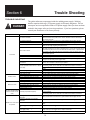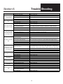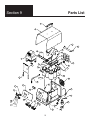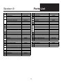
1
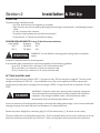
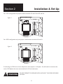
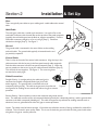
ILM004B
June, 2004
Price
$5.50 USD
Operation Manual
Capacitor Discharge Stud Welding Power Source CD110
BE SURE THIS INFORMATION REACHES THE OPERATOR. EXTRA COPIES ARE AVAILABLE THROUGH YOUR SUPPLIER.
CAUTION
THESE INSTRUCTIONS ARE FOR EXPERIENCED OPERATORS. If you are not fully familiar with the
principles of operation and safe practices for arc welding equipment, we urge you to read AWS SP “Safe Practices” available from the American Welding Society.
Do NOT permit untrained persons to install, operate, or maintain this equipment. Do NOT attempt to
install or operate this equipment until you have read and fully understand these instructions. If you do
not fully understand these instructions, contact your supplier for further information. Be sure to read
the Safety Precautions before installing or operating this equipment.
Table of Contents
SECTION 1:
Safety Precautions
3
SECTION 2:
Set Up
7
SECTION 3:
Normal Operation
10
SECTION 4:
Trouble Shooting
14
SECTION 5:
System Maintenance
16
SECTION 6:
Schematic Diagram
17
SECTION 7:
Part List
18
WARRANTY
Image warrants that the goods sold will be free from defects in workmanship and material. This warranty is expressly in lieu of other warranties,
expressed or implied or for fitness for a particular purpose. The liability shall arise only upon return of the defective goods at Buyer’s expense after
notice to Image. The warranty shall be limited to replacement with like goods or, at Image’s option, to refunding the purchase price. Image will not
accept receipt of equipment returned unless buyer has previously afforded Image’s personnel a reasonable opportunity to inspect and repair said
equipment. Image will warrant components for 1 year and labor for 180 days from date of shipment. Image shall not be liable for any
consequential damages including improper set up by buyer.
USERS RESPONSIBILITY
This equipment will perform in conformity with the description contained in this manual and accompanying labels and/or inserts when installed,
maintained and repaired in accordance with the instructions provided. This equipment must be checked periodically. Defective equipment should
not be used. Parts that are broken, missing, worn, distorted or contaminated should be replaced immediately. Should such repair or replacement
become necessary, the manufacturer recommends that a telephone or written request for service advice be made to the Authorized Distributer from
whom purchased.
This equipment or any of it’s parts should not be altered without the prior written approval of the manufacturer. The user of this equipment shall
have the sole responsibility for any malfunction which results from improper use, faulty maintenance, damage, improper repair or alteration by
anyone other than the manufacturer or a service facility designated by the manufacturer.
2
Section 1
Table o Safety Precautions
WARNING: These Safety Precautions are for your protection.
They summarize precautionary information from the references
listed in the Additional Safety Information section. Before
performing any installation or operating procedures, be sure to read
and follow the safety precautions listed below as well as all other
manuals, material safety data sheets, labels, etc. Failure to
observe Safety Precautions can result in injury or death.
PROTECT YOURSELF AND OTHERS Some welding, cutting, and gouging processes are noisy and require ear
protection. The arc, like the sun, emits ultraviolet (UV) and other radiation and can injure skin and eyes. Hot metal can
cause burns. Training in the proper use of the processes and equipment is essential to prevent accidents. Therefore:
1)
2)
3)
4)
5)
6)
Always wear safety glasses with side shields in any work area, even if welding helmets, face shields and goggles are also
required.
Use a face shield fitted with the correct filter. Cover sparks and rays of the arc when operating or observing operations. Warn bystanders not to watch the
arc and not to expose themselves to the rays of the electric-arc or hot metal.
Wear flameproof gauntlet type gloves, heavy long-sleeve shirt, cuffless trousers, high topped shoes, and a welding helmet or cap for hair protection, to
protect against arc rays and hot sparks or hot metal. A flameproof apron may also be desirable as protection against radiated heat and sparks.
Hot sparks or metal can lodge in rolled up sleeves, trousers cuffs or pockets. Sleeves and collars should be kept buttoned, and open pockets eliminated
from the front of clothing.
Protect other personnel from arc rays and hot sparks with suitable nonflammable partitions or curtains.
Use goggles over safety glasses when chipping slag or grinding. Chipped slag may be hot and can fly far. Bystanders should also wear goggles over
safety glasses.
FIRES AND EXPLOSIONS Heat from flames and arcs can start fires. Hot slag or sparks can also cause fires and explosions. Therefore:
1)
2)
3)
4)
5)
6)
7)
Remove all combustible materials well away from the work area or cover the materials with a protective nonflammable covering. Combustible materials
include wood, cloth, sawdust, liquid and gas fuels, solvents, paints and coatings, paper, etc.
Hot sparks or hot metal can fall through cracks or crevices in floors or wall openings and cause a hidden smoldering fire or fires on the floor below. Make
certain that such openings are protected from hot sparks and metal.
Do not weld, cut, or perform other hot work until the work piece has been completely cleaned so that there are no substances on the work piece which
might produce flammable or toxic vapors. Do not do hot work on closed containers. They may explode.
Have appropriate fire extinguishing equipment handy for instant use, such as a garden hose, water pail, sand bucket or portable fire extinguisher. Be sure
you are trained for proper use.
Do not use equipment beyond its ratings. For example, overloaded welding cable can overheat and create a fire hazard.
After completing operations, inspect the work area to make certain there are no hot sparks or hot metal which could cause a later fire. Use fire watchers
when necessary.
For additional information, refer to NFPA Standard 51B, “Fire Prevention in Use of Cutting and Welding Processes,” available from the National Fire
Protection Association, Batterymarch Park, Quincy, MA 02269
3
ELECTRICAL SHOCK Contact with live electrical parts and ground can cause severe injury or death. DO NOT use welding current in damp
areas, if movement is confined, or if there is danger of falling.
1)
2)
3)
4)
5)
6)
7)
8)
9)
Be sure the power source frame (chassis) is connected to the ground system of the input power.
Connect the work piece to a good electrical ground.
Connect the work cable to the work piece. A poor or missing connection can expose you or others to a fatal shock.
Use well-maintained equipment. Replace worn or damaged cables.
Keep everything dry, including clothing, work area, cables, torch/electrode holder and power source.
Make sure that all parts of your body are insulated from work and from the ground.
Do not stand directly on metal or the earth while working in tight quarters or a damp area; stand on dry boards or an insulating platform and wear rubbersoled shoes.
Put on dry, hole-free gloves before turning on the power.
Refer to ANSI/ASC Standard Z49.1 (listed on page 6) for specific grounding recommendations. Do not mistake the work lead for a ground cable.
ELECTRIC AND MAGNETIC FIELDS Electric and magnetic fields may be dangerous. Electric current flowing through any conductor causes localized Electric
and Magnetic Fields (EMF). Welding and cutting current creates EMF around welding cables and welding machines.
Therefore:
1)
2)
3)
Operators having pacemakers should consult their physician before welding. EMF may interfere with some pacemakers.
Exposure to EMF may have other health effects which are unknown.
Operators should use the following procedures to minimize exposure to EMF:
A) Route the electrode and work cables together. Secure them with tape when possible.
B) Never coil the torch or work cable around your body.
C) Do not place your body between the torch and work cables. Route cables on the same side of your body.
D) Connect the work cable to the work piece as close as possible to the area being welded.
E) Keep welding power source and cables as far away from your body as possible.
FUMES AND GASES Fumes and gases can cause discomfort or harm, particularly in confined spaces. Do not breathe fumes and gases.
Shielding gases can cause asphyxiation. Therefore:
1)
2)
3)
4)
Always provide adequate ventilation in the work area by natural or mechanical means. Do not weld, cut, or gouge on materials such as galvanized steel,
stainless steel, copper, zinc, lead, beryllium, or cadmium unless positive mechanical ventilation is provided. Do not breathe fumes from these materials.
Do not operate near degreasing and spraying operations. The heat or arc rays can react with chlorinated hydrocarbon vapors to form phosgene, a
highly toxic gas, and other irritant gasses.
If your develop momentary eye, nose, or throat irritation while operating, this is an indication that ventilation is not adequate. Stop work and take necessary
steps to improve ventilation in the work areas. Do not continue to operate if physical discomfort persists.
Refer to ANSI/ASC Standard Z49.1 (see listing on next page) for specific ventilation recommendations.
ELECTRICALLY POWERED EQUIPMENT
Faulty or improperly electrified equipment can cause injury or death.
Therefore:
1)
2)
3)
4)
Always have qualified personnel perform the installation, troubleshooting, and maintenance work. Do not perform any electrical work unless you are
qualified to perform such work.
Before performing any work inside a power source, disconnect the power source from the incoming electrical power using the disconnect switch at the fuse
box before working on the equipment.
Install equipment in accordance with the U.S. National Electrical Code, all local codes and the manufacture’s recommendations.
Ground the equipment in accordance with the U.S. National Electrical Code and the manufacturer’s recommendations.
4
CYLINDER HANDLING Cylinders, if mishandled, can rupture and violently release gas. Sudden rupture of cylinder, valve, or relief device can
injure or kill. Therefore:
1)
2)
3)
4)
5)
Use the proper gas for the process and use the proper pressure reducing regulator designed to operate from the compressed gas cylinder. Do not use
adaptors. Maintain hoses and fittings in good condition.
Always secure cylinders in an upright position by chain or strap to suitable hand trucks, undercarriages, benches, walls, post, or racks. Never secure
cylinders to work tables or fixtures where they may become part of an electrical circuit.
When not in use, keep cylinder valves closed. Have valve protection cap in place if regulator is not connected. Secure and move cylinders by using
suitable hand trucks. Avoid rough handling of cylinders.
Locate cylinders away from heat, sparks, and flames. Never strike an arc on a cylinder.
For additional information, refer to CGA Standard P-1, “Precautions for Safe Handling of Compressed Gases in Cylinders”, which is available from
Compressed Gas Association, 1235 Jefferson Davis Highway, Arlington, VA 22202
HEARING PROTECTION Prolonged Noise from Capacitor Discharge welding applications can damage hearing if levels exceed limits specified by
OSHA. Therefore:
1)
2)
3)
Use Approved ear plugs or ear muffs if noise level is high.
Warn others nearby about noise hazard.
For additional information, refer to OSHA Safety Standards 3074.
EYE PROTECTION Flying metal can injure eyes. Welding, chipping, wire brushing and grinding can cause sparks and flying metal. As
welds cool, they can throw off slag. Therefore:
1)
2)
Wear approved safety glasses with side shields even under your welding helmet.
Warn others nearby about flying metal hazard.
EQUIPMENT MAINTENANCE Faulty or improperly maintained equipment can cause injury or death.
Therefore:
1)
2)
3)
4)
5)
6)
Always have qualified personnel perform the installation, troubleshooting, and maintenance work. Do not perform any electrical work unless you are
qualified to perform such work.
Before performing any maintenance work inside a power source, disconnect the power source from the incoming electrical power.
Maintain cables, grounding wire, connections, power cord, and power supply in safe working order. Do not operate any equipment in faulty condition.
Do not abuse any equipment or accessories. Keep equipment away from:
- heat sources such as furnaces
- wet conditions such as water puddles and inclement weather
- oil or grease
- corrosive atmospheres.
Keep all safety devices and cabinet covers in position and in good repair.
Use equipment only for its intended purpose. Do not modify it in any manner.
5
MOVING PARTS CAN CAUSE INJURY Electric fan can start at any time without warning and cause severe injury, therefore:
1)
2)
3)
4)
5)
Always disconnect electrical power prior to service to prevent the fan from starting unexpectedly.
Keep all doors, panels, covers, and guards closed and securely in place.
Have only qualified people remove guards or covers for maintenance and troubleshooting as necessary.
Keep hands, hair, loose clothing, and tools away from moving parts.
Reinstall panels or guards and close doors when servicing is finished and before reenergizing welder.
ADDITIONAL SAFETY INFORMATION For more information on safe practices for electric arc welding refer to the following publications:
The following publications, which are available form the American Welding Society, 550 N.W. LeJuene Road, Miami, FL 33126, are recommended to you:
1)
ANSI/ASC Z49.1 - “Safety in Welding and Cutting”
2)
AWS C5.1 - “Recommended Practices for Plasma Arc Welding”
3)
AWS C5.6 - “Recommended Practices for Gas Metal Arc Welding”
4)
AWS SP - “Safe Practices” - Reprint, Welding Handbook.
5)
ANSI/AWS F4.1, “Recommended Safe Practices for Welding and Cutting of Containers That Have Held Hazardous Substances.”
This symbol appearing throughout this manual means
ATTENTION! BE ALERT!
Your safety is involved.
The following definitions apply to DANGER, WARNING, CAUTION found
throughout this manual.
DANGER
Used to call attention to immediate hazards
which, if not avoided, will result in immediate,
serious personal injury or loss of life.
WARNING
Used to call attention to potential hazards
which could result in personal injury or lost of
life.
CAUTION
Used to call attention to hazards which could
result in minor personal injury.
6
Section 2
Installation & Set Up
LOCATION
The power supply should be located:
• On a flat, level surfaces with adaquate air circulation
• Near the work area to limit welding cable length (shorter lengths are preferred). Avoid looping the weld
cables
• In a dry area away from moisture.
• To protect it from grinding dust and other contaminates.
• To provide min. 6” clearance on all sides for cooling.
POWER REQUIREMENTS Fusing / Cable Recommendations
Input Voltage
Frequency
Fusing
110 V
50/60Hz
15A
220 V
50/60Hz
10A
WARNING
WARNING: Do not defeat the incoming power cable ground on the power
supply.
Extension Cord specifications for incoming power:
If an extension cable is required (one is not recommended) use the following guidelines
Up to 25 ft. (8 meters) use a minimum of 16-3 wire extension cable
30 ft. (10 meters) use a minimum of 14-3 wire extension cable
50 ft. (15 meters) use a minimum of 12-3 wire extension cable
SETTING JUMPER LINKS
This power supply ships pre-wired as 110V. If you plan on using 110V no changes are required. The unit can be
configured to operate on 220V AC . If you would like to wire your unit to operate on 220V the jumper link
arrangement (and the power cord plug) must be changed. NOTE: Charge time will not vary between 110 and
220V.
DANGER
WARNING. Always be careful when working inside a capacitor storage unit.
Always disconnect the incoming power line when working inside of electrical
equipment. Even though the power switch is off and the power cable is
disconnected, there can still be voltages inside the unit.
Incorrect connection of the voltage select jumpers can damage the welding power supply. If you are not comfortable
changing the jumper links seek help from your distributor or a trained electrician.
Remove the power supply lid by unscrewing eight (8) #10 hex head screws (5/16 wrench or nut runner).
The main transformer has configurable jumper links. These are located directly on the main transformer on the top
side of the transformer nearest the rear of the unit. There are two jumper wires connected to the transformer.
7
Section 2
Installation & Set Up
For a 110V configuration the jumpers connect terminals H1 and H3 and H2 and H4.
Figure 1
110 V
110 V
H4 H3 H2 H1
For a 220V configuration only one jumper is used between terminals H2 and H3.
Figure 2
220 V
H4 H3 H2 H1
If connecting as a 220V unit, be sure and place the extra jumper in a safe place. You will need it to reconnect the
unit to 110V.Replace the cover and reinstall the 8 #10 hex head screws.
WARNING
DO NOT OPERATE THE POWER SUPPLY WITHOUT THE COVER SECURELY
IN PLACE.
8
Section 2
Installation & Set Up
Guns
There are typically two cables on your welding tool: a weld cable and a control
cable.
Dot
Weld Cable
The weld (gun) cable has a camlok style connector. Line up the flat on the
weld cable connector with the small dot on the top side of the panel receptacle
(typically the weld cable goes into the black or negative receptacle). Push the
weld cable connector straight in as far as it will go [Step 1]. Hand turn
clockwise to be tight [Step 2]. See Figure 3
Ground
The ground cable is connected in the same fashion as the welding
tool weld cable. The ground cable typically is inserted into the red
(or positive) receptacle.
Flat
2
1
Figure 3
Control Cable
There is a key in the end of the control cable connector. Align the key in the
cable connector with the key way in the front panel control cable receptacle.
Push the cable connector into the front panel receptacle [Step 1]. When the
two are seated turn the screw ring on the cable connector clockwise [Step 2].
This will lock the two together. See Figure 4. The screw ring does
Key
not need to be overly tight.
Cable Connections
Straight Polarity: In straight polarity the weld tool (gun) is
1
connected to the black receptacle labeled gun (this is electrode negative). The ground lead is connected to the red
receptacle (often ground). This cable arrangement is the preferred
Figure 4
arrangement for welding ferrous metals with either the gap or contact
processes.
2
Key way
Reverse Polarity: Reverse polarity reverses the weld tool and ground connections. The weld tool connects to the red receptacle labeled ground (this is electrode positive) and the ground cable
connects to the black receptacle (labeled gun). This cable arrangement is preferred for welding materials such as
aluminum, brass or galvanized with either the gap or contact processes.
Layout: The cables must be laid out straight. If the cables are coiled the amount of energy available for weld will be
reduced. This will result in poor quality welds. This is true for both the gun weld cable and the ground cable when
using either the gap or contact processes.
9
Section 3
Normal Operation
Voltage
Adjustment Knob
Voltage Display
(Amber) Lights when
there is a good weld path
(Red) Lights when gun
trigger is pulled
Capacitance
Adjustment Knob
(Green) Lights when welder
is ready to weld
DISPLAY FUNCTIONS
The main Weld Voltage Display shows the voltage that will be used for welding.
There are 3 indicator lights.
Trigger (Red)
This indicator lights when the trigger is pulled. This shows there is a good connection
through the gun trigger switch and cables.
Contact (Amber) This indicator lights when the unit detects contact with the work. This means there is a
good welding path.
Ready (Green)
This indicator lights when the unit is ready to weld. If the operator decreases the weld
voltage, this light will go out for a moment as the proper voltage is reached. This light
can also flash out error codes if certain error conditions occur (see troubleshooting for
specific error conditions).
ROTARY KNOBS
Voltage Control Knob
The upper rotary knob controls the weld voltage. Turning the knob clockwise increases the weld voltage up to
about 190V, turning the knob counter clockwise will decrease the weld voltage down to about 40V. The power
supply will take a moment to achieve the desired setting. Small changes make it easier to hit a target voltage level.
10
Section 3
Normal Operation
Capacitance Select Knob
The lower rotary knob has 3 positions. The operator can select from 3 different capacitance levels.
Low: 66,000uF
Medium: 88,000uF
High: 110,000uF
These different capacitance levels allow the power supply to be fine tuned to match the exact welding application for
the highest quality, most repeatable results.
POWER UP
Before power up, make sure all cables are properly connected. It is also a good practice to turn the voltage control
knob to the minimum voltage (all the way counter clockwise). Press the power switch (to the right or towards the
1), located on the lower left side of the control panel.
On power up the power supply initiates a self test. This test lasts approximately 2 seconds. The power supply will
then charge the level of capacitance set by the capacitance select knob to the voltage level set by the voltage select
knob. When charging is complete (3 seconds maximum) the ready light will turn on. Note: If the trigger is held or
the weld gun is in contact with the work, charging will be disabled until the trigger is released and/or the weld gun is
not in contact with the work.
WELDING
Stud Gun Settings
Refer to Stud Gun Manual
Welding Sequence
Position the gun against the work. Press down on the stud gun to make sure the spark shield or tripod legs sits
firmly against the work. While holding the gun in position, pull the trigger. The weld will initiate and complete.
There is a loud bang (hearing protection is recommended) associated with the weld process. This completes a weld
sequence. Note: Contact must be made BEFORE the trigger is pressed, otherwise welding will not occur.
Post Weld Sequence
After the weld is complete, but before the gun is pulled off the work, the unit will charge up to about 20V. When
the gun is pulled off the work (and the trigger is released) it will fully charge to the set point. If the operator pulls
the gun off the work immediately (and releases the trigger) the unit will charge to the set point. Pull the gun off of
the stud.
SET UP
Base Metal Preparation
As with most welding, clean weld studs and clean base metal will provide the best results. Typical weld penetration
is .002 to .004 inches (.05 to .1 mm). Mill scale may easily be this thick. When welding to steel with mill scale, the
scale must be removed first to achieve quality weld results.
11
Section 3
Normal Operation
A common CD welding mistake is to use a centerpunch mark for location. The ignition tip locates nicely in the
centerpunch mark, but it effectively shortens the tip length. Since the tip is sitting in a depression, the distance from
the workpiece to the face of the weld stud is shorter. Usually, this results in bad welds.
Aluminum can quickly form a layer of oxide. Oxide is non-conductive (not good for welding) and is tough. If
welding onto aluminum is causing problems, it is often best to remove the oxide layer. This can be accomplished via
abrasives. A stainless steel brush works well.
Recommended Power Supply Capacitance and Voltage Settings
Contact Gun
Stud Size
12 ga
10 ga
#4
#6
#8
#10
1/4
5/16
3/8
6mm
8mm
Mild Steel
Capacitance Plunge
Low
1/8
Low
1/8
Low
1/8
Low
1/8
Med
1/8
Med
1/8
Med
1/8
Hi
3/16
Hi
1/4
Med
1/8
Hi
3/16
Spring
Low
Low
Low
Low
Low
Low
Low
Med
Hi
Low
Med
Voltage
60
90
65
75
85
95
125
140
170
125
140
Stainless Steel
Capacitance Plunge Spring
Voltage
Aluminum
Capacitance Plunge Spring
Voltage
Low
Low
Med
Med
Med
Hi
1/8
1/8
1/8
1/8
1/8
3/16
Med
Med
Med
Med
Med
Med
70
75
85
95
130
150
Low
Med
Med
Med
Med
1/8
1/8
1/8
1/8
1/4
Hi
Hi
Hi
Hi
Hi
75
80
90
105
150
Med
Hi
1/8
3/16
Med
Med
130
150
Med
1/4
Hi
150
Acceptable Material Combinations
Typical Combinations of Base Metal and Stud Metal for Capacitor
Discharge Stud Welding
Base Metal
Low carbon steel, AISI 1006 to 1022
Stud Metal
Low carbon steel, AISI 1006 to 1010, stainless
steel, series 300*, copper alloy 260 and 268
(brass)
Stainless steel, series 300* and 400
Low carbon steel, AISI 1006 to 1010, stainless
steel, series 300*
Aluminum alloys, 1100, 3000 series, 5000 Aluminum alloy 1100, 5086, 6063
series, 6061 and 6063
ETP copper, lead free brass, and rolled
Low carbon steel, AISI 1006 to 1010, stainless
copper
steel, series 300*, copper alloys 260 and 268
(brass)
Zinc alloys (die cast)
Aluminum alloys 1100 and 5086
*Except for the free-machining Type 303 stainless steel.
12
Section 3
Normal Operation
Weld Quality
Visual Inspection
Too Hot
Excessive weld flash
and weld spatter.
This weld may break.
Correct
Normal weld flash.
No significant weld spatter.
This will be a good, strong weld.
Too Cold
No visible weld flash.
This weld will break.
Reduce Voltage,
Increase Spring Pressure,
or Reduce Capacitance
No Adjustments Required
IncreaseVoltage,
Reduce Spring Pressure,
or Increase Capacitance.
Also could be caused by a
short tip or a center punch mark
CONTACT CAPACITOR DISCHARGE PROCESS
The gun begins
to drive the stud
into the base metal
CD Stud is positioned against work
on the timing or ignition tip,
the gun mechanisms are compressed.
Complete fusion
The Trigger is pulled, the ignition
tip vaporizes and an arc is formed.
This arc melts the bottom of the
stud and top of the base metal.
At the end of travel, the power source
is completely discharged and the stud
has formed a complete bond with the
base material.
Note: The tip design/dimensions are very important. The ignition tip controls the arc length and weld duration. If
the ignition tip is too short there will not be enough weld time to ensure an adequate weld.
13
Section 6
Trouble Shooting
TROUBLE SHOOTING
DANGER
Problem
This guide references components inside the welding power supply. Working
inside a capacitor discharge (CD) power supply is inherently dangerous. Do not
attempt to service components inside a CD power supply unless you have not been
trained in the proper safety and service procedures. If you have questions, please
consult your distributor or the factory directly.
Possible Cause
Poor surface condition.
Poor ground connection.
Broken or loose cables.
Use of center punch or witness marks.
Loose collet or chuck.
Poor weld.
Dirt in gun preventing smooth operation.
Cables are coiled.
Voltage incorrect for size stud to be welded.
Studs or pins are not perpendicular to the
work surface.
Corrective Action
Properly prepare the weld surface. Make sure it is free of contaminants such as dirt
and oil. If there is heavy oxide (rust for steel or aluminum oxide for aluminum) it
must first be removed.
Make sure all cable connections are in good condition and are tightly secured.
Make sure all cable connections are in good condition and are tightly secured.
Do not use centerpunch/witness marks to locate CD weld studs. They effectively
reduce the tip length degrading weld performance.
The collet should have a firm hold on the weld stud. If you are able to easily (with no
real resistance) pull the stud out of the collet then the collet is worn. Replace Collet.
If the inside of the collet looks like there are threads in it then the collet is worn out
and should be replaced.
Service gun per your gun's service manual.
Uncoil weld and ground cables.
Check the weld parameter table on page 11 to ensure that you are using the correct
voltage for the size stud you are trying to weld.
If the operator can not suitably hold the welding tool perpendicular to the work
surface, then a template or fixture may be required.
Use double grounds, one on each side of the weld zone to balance current flow.
Arc blow (all weld material moves or "blows"
Move ground connections away from weld zone.
to one side).
Space ground connections evenly around weld zone.
Incorrect plunge setting.
Adjust plunge per gun's service manual.
Incorrect spring rate.
Adjust spring pressure per the gun's service manual.
Weld voltage too high.
Turn the voltage adjust knob counter-clockwise to decrease weld voltage.
Capacitance set too high.
Turn the capacitance knob counter-clockwise to charge fewer banks.
Weld is too hot.
Gap too small when using gap process.
If using a gap gun, increase the weld gap per gun's service manual.
Plunge too small.
Increase the plunge per gun's service manual.
Spring pressure to low.
Increase the spring pressure per the gun's service manual.
Weld voltage too low.
Turn the voltage adjust knob clockwise to increase weld voltage.
Capacitance set too low.
Turn the capacitance knob clockwise to charge more banks.
Weld is too cold.
Gap too large when using gap process.
If using a gap gun, decrease the weld gap per the gun's service manual.
Plunge too large.
Decrease the pluge per gun's service manual.
Spring pressure too high.
Decrease the spring pressure per the gun's service manual.
Reposition ground clamp to "steer" weld material. Weld material will flow away from
Arc blow (all weld material
the ground clamp.
moves or "blows" to one Ground(s) not positioned properly.
side).
Use double grounds, one on each side of the weld zone to balance current flow.
Broken ground cable or incomplete
connection.
Broken gun weld cable or incomplete
connection.
Welder turns on but does Broken control cable.
not operate.
Shorted trigger switch (trigger LED always
on).
Faulty trigger switch (trigger LED doesn't light
when trigger pulled).
Faulty control board.
Make sure all cable connections are in good condition and are tightly secured.
Make sure all cable connections are in good condition and are tightly secured.
Verify continuity on all leads in the control cable (black and white only for contact
guns).
Verify continuity on the trigger switch. Replace if defective.
Verify continuity on the trigger switch. Replace if defective.
Replace control board.
14
Section 6
Problem
Possible Cause
Shorted main charge SCR.
Shorted bank charge SCR.
Welds too hot regardless
of voltage setting.
Faulty voltage potentiometer.
Faulty control board.
Disconnected LED.
Green ready LED doesn't
Faulty LED.
light.
Faulty control board.
Voltage Adjust knob turned up too high
Green ready LED blinks,
Faulty voltage potentiometer.
welder does not operate.
Faulty bank select switch.
Faulty control board.
Missing or faulty ground.
Yellow contact LED
Broken sense wire (gap gun).
doesn't light when gun is
Disconnected LED.
placed against work.
Faulty LED.
Faulty control board.
Broken control cable.
Red trigger LED doesn't
light.
Trouble Shooting
Corrective Action
Replace charge SCR.
Replace charge SCR.
Verify voltage pot wiper has a resistance of 0-500 ohms. Replace if defective.
Replace control board.
Ensure LED is seated in holder and holder is pressed firmly onto bezel.
Replace LED.
Replace control board.
Turn the Voltage adjust knob counter-clockwise. Check voltage adjust potentiometer
for correct functionality.
Verify voltage pot wiper has a resistance of 0-500 ohms. Replace if defective.
Verify switch selects one output per position. Replace if defective.
Replace control board.
Make sure all cable connections are in good condition and are tightly secured.
Verify continuity on all leads in the control cable.
Ensure LED is seated in holder and holder is pressed firmly onto bezel.
Replace LED.
Replace control board.
Verify continuity on all leads in the control cable (black and white only for contact
guns).
Control cable not fully connected.
Make sure all cable connections are in good condition and are tightly secured.
Faulty trigger switch.
Disconnected LED.
Faulty LED.
Faulty control board.
Verify continuity on the trigger switch. Replace if defective
Ensure LED is seated in holder and holder is pressed firmly onto bezel.
Replace LED.
Replace control board.
Shorted weld capacitor.
Circuit fuse or CD110
breaker blows each time
Shorted bridge rectifier.
unit is powered on.
Incorrect primary connections.
Shorted transformer.
Not plugged in.
Breaker blown.
Welder does not turn on.
Faulty power switch.
Faulty control board.
Weld SCR shorted.
Welder shuts down
Faulty power switch.
immediately.
Faulty control board.
Charge SCR shorted or open.
Welder shuts down in a
Faulty power switch.
few seconds.
Faulty control board.
Welder shuts down after a Charge SCR shorted or open.
few minutes.
Faulty control board.
Weld SCR shorted or open.
Breaker blown.
Welder shuts down after a Faulty power switch.
weld.
Incorrect gap gun adjustment.
Faulty control board.
Use a capacitance meter to test function of each weld capacitor. Visually inspect
weld capacitors for obvious signs of damage. Replace any defective weld capacitor.
Replace bridge rectifier.
Check the jumper links on the transformer.
Replace transformer.
Plug in unit.
Reset breaker.
Replace power switch.
Replace control board.
Replace weld SCR.
Replace power switch.
Replace control board.
Replace charge SCR.
Replace power switch.
Replace control board.
Replace charge SCR.
Replace control board.
Replace weld SCR.
Reset breaker.
Replace power switch.
Gap process welds must complete within 400ms of trigger pull. Make adjustment per
your gun's service manual.
Replace control board.
15
Section 7
System Maintenance
SYSTEM MAINTENANCE
Power Supply
This system has been designed to be essentially maintenance free.
The only recommended maintenance is to blow out the power supply once a year. Dirt, grinding dust and other
contaminates can accumulate over time and they deteriorate the power supply’s cooling performance.
If the unit is located in a dirty environment the unit should be blown out more frequently.
Welding Tool
Typically, most trouble stems from the stud gun. The stud gun should be serviced once every quarter. Monthly
service may be required if use is exceptionally heavy. Please refer to the stud gun service manual for maintenance
guidelines and instructions.
Cables
Cables are also a frequent source trouble. Users often drag the power supply around by the cables. This can
damage cables. Whenever gun service is performed, the cables should be visually inspected for worn / damaged
insulation or fraying wire. If the cables are damaged they should be repaired to prevent any degradation of weld
quality.
BUILT IN EQUIPMENT SAFETY
A fault in the welding power supply can create a potentially dangerous condtion. The microprocessor continually
monitors the system for faults and shuts the unit off when one is detected. This is done for operator and
equipment safety purposes. The unit can be restarted, but will shut down again as soon as the fault condition is
detected. The unit must be repaired.
16
Schematic Diagram
Section 8
Wire 1
Wire 2
Wire 3
Wire 4
Wire 5
Wire 6
Wire 7
Wire 8
Wire 9
Wire 10
Wire 11
Wire 42
Wire 13
Wire 15
Wire 17
Wire 18
Wire 19
Wire 20
Wire 21
Wire 22
Wire 23
Wire 24
WIRE-5
WIRE-18
WIRE-22
WIRE-20
WIRE-24
J8
BLACK
WHITE
BLUE
BROWN
GUN CONNECTOR
1 WHITE J3
2 BLACK GREEN - READY
1 WHITE J4
2 BLACK YELLOW - CONTACT
-
4
D3
BRIDGE
+
1 WHITE J5
2 BLACK RED - TRIGGER
2
2
WIRE-41
WIRE-42
2
78
1
Q3
3
910
4
11
2
SW3
N.O. FAN
THEMALSWITCH
56
1
J14
WIRE-29
AC1
AC2
WIRE-29
WIRE-15
12
T1
R5
FAN
C1
Primary
Bank
C2
R2
WIRE-21
C3
Q1
C4
Bank #1
D1
WIRE-23
3
R3
C5
Q2
2
R1
Bank #2
1
D2
R4
Q4
SW1
9
8
7
12
11
10
Revision D
WIRE-10
1
2
3
C7
C6
WELD-
J10
WELD+
J9
BANK SELECT
4
5
6
13
17V 1A
17V 1B
17V 3A
17V 3B
L1 Hot
VSET Low
L2 Hot
VSET High
120 VAC
Bank Switch Pin13
Breaker Trip
Neutral
Cap Minus
Charge SCR Gate
Gun Common (Black)
Bridge Plus
Coil RTN (Blue)
Bank1 SCR Gate
Trigger RTN (White)
Bank2 SCR Gate
Gun Ground Ring (Brown)
Wire 26
Wire 27
Wire 28
Wire 29
Wire 30
Discharge Resistor
Weld Minus
Weld SCR Gate (White)
Bank Switch Pin3
Cap Plus
Bank Switch Pin 2
12(k) WIRE-9
WIRE-7
1
SW2
N.O. SHUTDOWN
THEMALSWITCH
WIRE-17
J13
17
Wire 32
Wire 33
Wire 34
Wire 35
Wire 36
Wire 37
Wire 38
Wire 39
Wire 40
22(k) WIRE-12
15
14
13
12
11
10
9
8
7
6
5
4
3
2
1
1
3
VSET Sig
Ready LED White
Ready LED Black
Trigger LED White
Trigger LED Black
Contact LED White
Contact LED Black
17V 2A
17V 2B
11
12(n)
SW4
12
21
WIRE-42
WIRE-11
15
14
13
12
11
10
9
8
7
6
5
4
3
2
1
J6
WIRE-13
1
2
3
4
5
6
7
8
9
10
11
12
13
14
15
16
17
18
19
20
21
22
23
24
25
26
27
28
29
30
31
32
33
34
35
36
37
38
39
40
CONTROL BOARD
J1
WIRE-43
WIRE-44
2
J2
WIRE-19
J11 J12
WIRE-49
WIRE-47
WIRE-48
WIRE-46
J7
PLUG AC MALE
1
3
WIRE-13
WIRE-27
WIRE-26
Section 9
Parts List
1
2
11
12
7
4
8
10
9
5
7
6
13
3
14
19
17
15
to #24
16
18
20
6
22
23
26
to #34
27
24
28
25
29
31
30
32
33
35
Red
Yellow
Green
34
36
37
42
38
39
41
40
18
Section 9
Item
01
02
03
04
05
06
07
08
09
10
11
12
13
14
15
16
17
18
19
20
22
23
24
25
26
27
Description
Handle
Handle Screw
Sheet Metal Cover
Cover Screws
Transformer
Transformer Mounting Nut
Transformer Mounting Screw
Transformer Voltage Select Jumper
Diode Insulator
Bank Select Diode
SCR
SCR Insulator Kit
#10-32 X 1/2 Hex Screw
#10 Bellville Washer
Isolator Shoulder Washer
#10-32 x 3/8 Hex Screw
Discharge Resistor
Resistor Bracket
Positive Buss Bar
Negative Buss Bar #1
Cooling Fan
Fan Mounting Screw
Bridge Rectifier
Control Printed Circuit Board
Capacitor Retention Block
Negative Buss Bar #2
Charge Resistor
Charge Resistor Mounting Screw
Weld Capacitor
Capacitor Retention Strap
Card Guide
Positive Jumper
Coupling Nut
Connector Stud
Fan Guard
Parts List
Part Number
PKM111
PPC31-62ZP
PKS240
HSC19-37ZP
PKE501
NUC25-50
PPC25-50ZP
PKH002
EI001
ED5004
ESR5006SM
EI002
HBC19F-50ZP
WBC19
WSN20-40-06X26-50
HBC19F-37ZP
ER100W-100
ERB-50
PKE2210
PKE2220
PKE900
BHC16-125
EBR03504Q
PKP101
PKK300
PKE2230
ER50W-10A
PPC11-37ZP
EC200-22KE
CTN19-14.5
PKK101
CW2SR-.65
NCC19-75ZP
TRC19-5
PKM900
19
Item
Description
28 Knob
29 Face Plate Decal
30 Voltage Meter
Power Cord
31
Cord Grip
Meter Bezel
32
Bezel Push Nut
33 Capacitance Selector Switch
34 Weld SCR
Red LED Lens
Yellow LED Lens
Green LED Lens
35
Red LED
Yellow LED
Green LED
36 Power Switch/Breaker
37 Red Ground (+ pos) Cable Connector
38 Black Weld Cable (- neg) Connector
39 Control Cable Connector
40 Chassis
41 Voltage Select Potentioneter
42 Weld SCR Mounting Bracket
Part Number
PAM110
PKD225
PKE101
PKE9000
PKM50
PKM101
PKM102
PKE2
PKE4
PKM81
PKM82
PKM83
ELED-R5
ELED-A5
ELED-G5
PKE101
CCL1/0RFR
CCL1/0RFB
CSS4MR
PKC225
ERV25-500
PKE2120
Items Not Shown
43 Wiring Harness
44 Filter Network Weld Output
45 Weld Capacitor Tie Down Strap
PKH001
PAE801
CTN19-14.5
Please visit us on the web at www.imageindustries.com