1
New 2012 Edition
Parts & Service Manual
35-60 TON GSL
Table of Contents
Standard Model Drawings
Gooseneck Operating Instructions
Gooseneck Hydraulic Schematics
Gooseneck Hydraulic Components
Engine Controls and Filters
Lowboy Decal Schematics & Manifest
Lowboy Front Flip Ramps
Lowboy Rear Ramps
Hub and Drum Assemblies
Brake Shoes and Springs
Slack Adjuster Determination
Cam Shaft Determination
Cush CLY-25-209
Cush CLU-25-009
Cush CAL-01
Cush CUU-25B09L (Hi Lift)
Cush Ride Height Setting
Barksdale Ride Height Control Valve
Cush Air Ride Valves
Hutch 900-50 Suspension
Hutch 9700 Suspension
Lowboy Air Schematics
Removable Axle Operating Instructions
Spread Axle Shimming and Scaling
Flip Axle with Lift Air System
Flip Axle (without Lift Air System)
Booster Flip Axle Air System
Booster and Flip Axle Pins
Electrical Harness with LED Lights
Electrical Wiring Schematics
Auxiliary Flasher Kit (PLUS)
Strobe Light Kit
Miscellaneous Parts List
OPERATION & SERVICE MANUAL
Parts
(800) 338-7088
Customer Service
(800) 722-8803
ext: 3251
Page #
2
4
7
8
9
10-11
12
13-14
15-17
18
19
20
21
22
23
24
25
26
27
28-29
30
31-40
41-42
43
44
45
46
47
48-49
50-51
52
53
54
APPENDED
Sales
(800) 257-8163
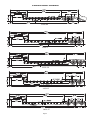
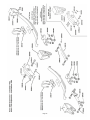
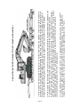
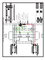
STANDARD MODEL DRAWINGS
35GSL/BR
35GSL-S
35GSL-S4S
35GSL-PT
50GSL/PT
Page 2
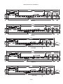
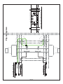
STANDARD MODEL DRAWINGS
50GSL/3
55GSL/3
55GSL/BR
60GSL/3
60GSL/BR
Page 3
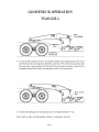
GOOSENECK OPERATION
35-60 GSL’s
Page 4
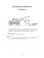
GOOSENECK OPERATION
35-60 GSL’s
Page 5
GOOSENECK OPERATION
35-60 GSL’s
Page 6
Page 7
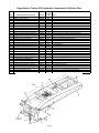
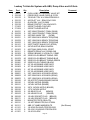
Eager Beaver Trailers GSL Hydraulic Components & Cylinder Pins
Item
1
1
1
2
2
2
2
2
3
3
4
4
5
6
7
8
8
8
8
8
8
8
8
9
9
10
10
11
11a
12
13
Hydraulic System Components
Stinger Cylinder - All GSL
Pin Set - Stinger Cylinder
Clevis End - Stinger Cylinder
35-40 GSL Lift Cylinder After 1987
35 & 50 GSL-PT Lift Cylinder after 8/2002
50 GSL Lift Cyl After July 1994
55 & 60 GSL Lift Cyl After July 1995
55 & 60 GSL-PT Begin Mar 2010
Hauling Pin Cylinder - All GSL
Lower Pin (3.25" Cylinder-to-Hauling Pin)
Hauling Pin - All GSL Models
Hauling Pin - 35 & 50 PT models only
Hauling Pin Collar ("Doughnut")
Lift Cylinder Top Pin after 1989
Lift Cylinder Bottom Pin after 1989
Main Pivot Pin RH 35-40 Ton before 1994
Main Pivot Pin LH 35-40 Ton before 1994
Main Pivot Pin - LH 1994 - 2005
Main Pivot Pin - RH 1994 - 2005
Main Pivot Pin - LH 2005-Sept 2006
Main Pivot Pin - RH 2005-Sept 2006
Headless Pin Retro Kit (LH or RH)
Main Pivot Headless Pin Begin Oct 2006
King Pin (Weld on Replacement)
King Pin (Drop in) - Optional After 1995
Hydraulic Quick Disconnect - Male
Hydraulic Quick Disconnect - Female
Hydraulic Oil Filter
Hydraulic Oil Tank, 6 Gallon Capacity
3-Spool 4-Way Control Valve
Hyd Pump (6-10 GPM @ 2,500-3,00 PSI)
Part #
2060898
2060965
2062209
2060513
2062100
2062128
2062246
371206
2060922
2060923
2062188
2063319
2063097
2063081
2063082
2060871
2060872
obsolete
obsolete
2063085
2063086
2063089
2062292
2060054
405021
2059941
2059942
2056554
2059365
2060823
2059919
Packing
Kit Only
PN
2060804
N/A
N/A
2059965
2062235
2060907
2062234
Sp. Order
2060961
N/A
N/A
N/A
N/A
N/A
N/A
N/A
N/A
N/A
N/A
N/A
N/A
N/A
N/A
N/A
N/A
N/A
N/A
N/A
N/A
2060992
2062339
Page 8
Notes
Pre 1987 requires bottom mounting tube trim
Pre 8/2002 had 12.5" barrel length. Replace in pairs w 11.5"
55/60PT models only 7.75" Bore x 11.5" Stroke
Cylinder has internal safety relief valve on retract.
Top Pin (5.75" long Cylinder-to-Frame) PN 185511
Except Models 35GSL-PT and 50GSL-PT
Weld On - Underside of Alignment Tray
8" Long x 2" Diameter
11.75" Long x 2" Diameter
2.5" Diameter Pin
2.5" Diameter Pin
3" Dia; Replace with Headless Pin Retro Kit PN 2063089
3" Dia; Replace with Headless Pin Retro Kit PN 2063089
3" Dia; Keeper in Eng Compartment (or use Retro Kit)
3" Dia; Keeper in Eng Compartment (or use Retro Kit)
3" Dia; When Replacing old style pins, order qty 2 kits
3" Dia; 1 Pin & 2 Snap Rings (Central Lube Sys only)
SAE 2" - Fixed GN Swing Clearance (not removable)
SAE 2" - Multi-Position GN Swing Clearance (drop in from top)
3/4" Female NPT Thread
3/4" Female NPT Thread
25 Micron (Power Pack Trailers only)
Power Pack Trailers Only ( Chevron AW ISO 68 Hyd Oil)
O-ring Kit Only (Centering Spring Not Included)
Seal Kit includes Shaft Seal (shaft seal only, PN 2062289)
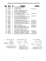
Eager Beaver Trailers
Power Pack Keys, Switches, Controls & Filters
Keys - Switch - Ignition Harness
Honda Ignition Key Only
Honda Ignition Switch
Honda Ignition Harness
Kohler Ignition Key Only
Kohler Ignition Switch
Kohler Ignition Switch Harness
Robins Ignition Key Only
Robins Ignition Switch
Robins Ignition Switch Harness
PN
2062001
2062147
2062150
2059876
2058207
2059202
2060892
2060848
2060897
Notes
Replacement Key Only
Includes Keys
72" Switch Extension Harness (between Switch and Engine)
Replacement Key Only
Includes Keys
All GFG-GHG and GSLs with Kohler Engines
Replacement Key Only
Includes Keys (Robins EY40, EH34 & EH41 Engines)
Choke & Throttle Cables
Choke Cable 96"
Honda 13HP Choke Linkage Kit
Throttle Cable 84" Long
PN
2059149
2062149
2059148
Notes
All Lowboys with Powerpack (Except Hatz Diesel)
Honda engine Only
All Lowboys with Powerpack
Filters & Starter Motors
Air Filter - HONDA
Air Filter - ROBINS EY40
Air Filter - ROBINS EH41
Starter Motor - HONDA
Hydraulic Oil Filter (25 Micron)
PN
2062145
2061022
2062270
2062146
2056554
Notes
Honda GX390
Robins EY 40 Only (Round, Cone Shaped)
Robins EH 41 Only (5 Sided, not Cone Shaped)
Honda GX390 up to SN GCANK 1414795 (2005 - 2007 only)
All Lowboys with Powerpack
Hydraulic Control Valve and Pump
Component
3-Spool 4-Way Control Valve
Replacement Handle
Black Ball Knob for Handle End
Handle, Knob & Linkage Kit
PN
2060823
2061080
2062189
2062266
Notes
Packing Kit Only PN 2060992
Handle only, no knob
Knob only, no handle
Hydraulic Pump
Seal Kit
Shaft Seal ONLY
Lovejoy half 9/16" shaft
Lovejoy half 1" shaft
Lovejoy half 1 1/8" shaft
Lovejoy Spider
Pump-to-Engine Mounting Housing
Pump-to-Engine Mounting Housing
2059919
2062339
2062289
2062324
2060478
2060477
2062325
2060267
372011
Prince SP-F26 **
Seal Kit includes Shaft Seal
Hydraulic Pump shaft (All Pumps)
Engine shaft - Honda, Robins Subaru, & Hatz Diesel Only
Engine shaft - Kohler Only
Honda, Robins Subaru, & Hatz Diesel only
Kohler only
Page 9
Page 10
Eager Beaver Trailers Lowboy Trailer Decals
PART #
2059016
2060618
2062005
2060608
2059181
2062007
2059162
2059370
2062208
2062173
QTY
2
2
2
48
2
1
2
2
1
1
2059329
2059348
2059585
2062009
2062010
2062011
2062012
1
1
1
9
1
1
1
With Detachable Hydraulic Gooseneck, Add the Following:
"HAULING PIN" DECAL
"HAULING PIN LEVER" DECAL
WARNING HAULING PIN" DECAL
"GREASE" FITTING DECAL
"LUBRICATION" DECAL
HAULING PIN "INTERLOCK WARNING" DECAL
COMPRESSION BLOCK NUT TIGHTEN DECAL
2062003
2061051
2062004
2062179
1
2
1
1
With ABS, Add the Following:
CAUTION TRAILER EQUIPPED W/ABS BRAKES
ABS DECAL(ALL WHEEL)
ABS INDICATOR LAMP INSTRUCTIONS
DANGER SPRING BRAKES
2063521
KIT
2059281
2059275
2059277
2062244
2059278
2
2
2
2
2
Add Trailer Model Decal (specify if "PT" or "BR" Model)
DECAL "25GLB" WHITE (specify if 35, 50 or 60 GLB)
DECAL "35GSL" WHITE
DECAL "50GSL" WHITE
DECAL "55GSL" WHITE
DECAL "60GSL" WHITE
2062245
2062143
1
1
With Cush Air Ride Suspension, Add the Following:
CUSH SUSPENSION TORQUE
AIRBAG EXHAUST OPERATION
2062249
2062008
1
1
With Pony Motor, Add the Following:
NOTICE - FUEL SHUT OFF VALVE
"HOT MUFFLER" DECAL
2062142
1
With a Lift Axle (All 50 - 60 Ton Trailers), Add the Following:
LIFT AXLE OPERATION
2
*For Goosenecks with Fenders or Relief Neck, Replace PN 2059370 with:
EAGER BEAVER TRAILERS DECAL - SMALL
2062020
DESCRIPTION
CHECK WHEEL LUGS DECAL
ROTO-RING™ DECAL
CAUTION CENTERLINE DECAL
RED/WHITE CONSPICUITY STRIPING ("DOT STRIPING")
"DO NOT SIDE LOAD" DECAL
WEB WHEEL TORQUE DECAL
RECOMMENDED TIRE PRESS DECAL
EAGER BEAVER TRAILERS DECAL - LARGE *
USA HARNESS DECAL
REPLACE DAMAGED WOOD DECAL
GSL WITH ABS DECAL KIT (Includes All Decals Listed Above)
Page 11
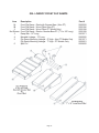
GSL LOWBOY FRONT FLIP RAMPS
Item
1A
1B
2
Not Shown
3
4
5
6
Description
Front Flip Ramp - Steel with Grouser Bars (Non-PT)
Front Flip Ramp - Wood Filled (Non-PT)
Front Flip Ramp - Wood Filled (PT Model Only)
Front Flip Ramp - Steel w Grouser Bars PT (7" H x 24" Long)
Ramp Bar - 16" Long
Movable Linkage - 13" Long
Flip Ramp Mounting Linkage - 9" High - Non PT Models Only
Flip Ramp Mounting Linkage - 7" High - PT Models Only
Split Pin
Page 12
Part #
2060550
2059196
2059198
2059199
2063071
2060500
2061071
2059201
2059020
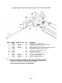
Lowboy Single Acting Rear Ramp Linkage - before September 2008
Item # Part No Alt Part No Qty
1
993880
1A
143721
2060553
2
1B
188205
2060866
1
2
993881
2059403
1
2A
143732
2
2B
218010
1
2C
143731
1
2D
168089
2
3
991822
2054640
1
4
402001
2059240
1
5
411601
2059020
1
Unit
EA
EA
AY
EA
EA
EA
EA
EA
EA
EA
Description
Order Items 1A & 1B Separately
Tailboard Fixed Linkage 1/2 X 4-5/8 X 11-3/4
Tailboard Hinge Pin 2" Dia. X 32"
BR Moveable Link Assy (Includes Items 2A, 2B, 2C, 2D)
Tailboard Movable Link 3/4 X 8.5X 11.125
2" SCH 40 X 18-3/8 SEAMLESS PIPE
Bar Link 1/2 X 4-1/2 X 8
Tailboard Link Spring Stop 1/2 X 2X 1.75
1.5" Dia. x 22" Dia Ramp Bar Assy
Heavy Duty Double Spring
Roll Pin - 5/16" Dia x 2.5" Long
Note: Item # 1 not available pre-assembled. Order 1A & 1B separately, as needed
Items # 1A & 1B require assembly at time of installation to trailer tailboard
Items # 3, 4, 5 and Ramps not included in any assembly
Item # 2 available as assembly under PN 2059403
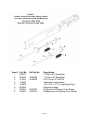
Page 13
Item #
1
2
3
4
5
6
7
8
Part No
991877
991876
411601
173642
178509
991863
402021
402007
Alt Part No
2063220
2059020
2062327
2062134
Description
2" Dia x 36.5" Ramp Bar
1.5" Dia x 25" Ramp Bar
5/16" Dia x 2.5" Roll Pin
Tailboard Fixed Linkage
1/2" x 3/4" x 17.5" Long Spring Stop
Rotating Linkage
Off-Ground Lift Spring (1 per Ramp)
Off-Beavertail Lift Spring (3 per Ramp)
Page 14
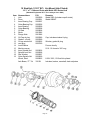
10 Stud Hub (11.25" BC) Uni-Mount (Hub Piloted)
16 ½" x 7" Outboard Drum with Webb 2023 Series Hub
(Standard Equipment 35-75 Ton Lowboys since 2000)
Item
1
2
3
4
5
6
7
8
9
10
11
12
13
14
15
16
17
18
19
Nomenclature
Hub
Drum
Inner Bearing Cup
Outer Bearing Cup
Inner Bearing
Outer Bearing
Oil Seal
Studs
Flange Nuts
Oil Cap w/ plug
Gasket - oil cap
Oil cap window kit
vent plug
Lock Washer
Machine screw
Inner Spindle Nut
Spindle Lock Nut
Star Washer
Outer Spindle Nut
Wheel, Steel
Axle Beam, 77" Trk
P/N
2062290
2062291
2058307
2058306
2058309
2058308
2055828
2061085
2061086
2055089
2055090
2058056
2055749
Remarks
Webb 2023 (Includes cups & studs)
Webb 66864F
Cap, includes window & plug
Window, gasket & plug
Procure locally
5/16 - 18 thread x 3/4" long
2055836
2058268
2058267
2059229
2060825
332101
8.25 X 22.5, 10 Stud Hub piloted
Includes, brakes, camshaft, slack adjusters
Page 15
10 Stud Hub (11.25" BC) Ball Seat Mount (Stud Piloted)
16 ½" x 7" Outboard Drum with Webb 2023 Series Hub
(Standard Equipment 35-60 Ton Lowboys 1997-2000)
Item
1a
1b
2
3
4
5
6
7
8a
8b
9a
9b
10a
10b
11
12
13
14
15
16
17
18
19
Nomenclature
Hub LH w Studs & Cups (no nuts)
Hub RH w Studs & Cups (no nuts)
Drum
Inner Bearing Cup
Outer Bearing Cup
Inner Bearing
Outer Bearing
Oil Seal
Stud, LH (Left Tighten)
Stud, RH (Right Tighten)
Inner Cap Nut - LH
Inner Cap Nut - RH
Outer Cap Nut - LH
Outer Cap Nut - RH
Gasket - oil cap
Oil Cap (complete)
Oil cap window kit
Oil Cap Rubber Plug
Machine screw & Lock Washer
Inner Spindle Nut
Spindle Lock Nut
Star Washer
Outer Spindle Nut
Rim, 10 Stud 8.25 x 22.5
P/N
Special Order
Special Order
2062291
2058307
2058306
2058309
2058308
2055828
Special Order
Special Order
2055701
2055538
2060878
2060879
2055090
2055089
2058056
2055749
Procure Locally
2055836
2058268
2058267
2059229
341018
# LH Hub with LH Studs go on Left Hand (Street Side) of Trailer
# RH Hub with RH Studs go on Righ Hand (Curb Side) of Trailer
Page 16
Remarks
Webb 20235-ML #
Webb 20235-MR #
Webb 66864F
HM218210
HM212011
HM218248
HM212049
Webb 101173
Webb 101172
Cap, includes window & plug
Window, screws, gasket & plug
Included with Window Kit
5/16 - 18 thread x 3/4" long
Special Order
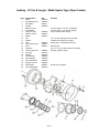
Lowboy - 35 Ton & Larger - Webb Spoke Type (Open Center)
Item
1
2
3
4
5
6
7
8
9
10
11
12
13
14
15
16
17
18
19
20
21
22
23
24
Nomenclature
Studs
Outer Bearing Cup
Rim Clamp
Rim Nut
Machine screw
Lock Washer
Oil Cap w/ plug
Gasket - oil cap
Spacer
Nut
Washer
Hub
Inner Bearing Cup
Drum
Capscrew
Oil cap window kit
Vent plug
Oil Seal
Inner Bearing
Outer Bearing
Inner Spindle Nut
Spindle Lock Nut
Star Washer
Outer Spindle Nut
P/N
2055084
2058306
2058317
2055085
2055089
2055090
2058316
2060453
2058307
2058313
2058056
2055749
2055828
2058309
2058308
2055836
2058268
2058267
2059229
Remarks
Procure locally - 5/16-18 x 3/4 Grade 5
Procure locally - 5/16-18 (fine thread)
Cap, includes window & plug
3/4" x 10 (incl with Dayton Kit 13-6583)
Included with Dayton Kit 13-6583
Webb 7520 - Includes Studs & Cups
Webb 67518
3/4" x 10 x 2" (incl with Dayton Kit 13-6583)
Window, gaskets, & plug
Not Shown in Diagram
Page 17
Page 18
94-'96 (PQ)
2060853
2060900
2055828
PQ Style
One End Closed
Upto '93 (P)
2055842
2058058
2055828
P Style
Both Ends Closed
Spicer Style
Both Ends Open
After '97 (Spicer)
2060455
2060956
2055828
* After 1998 most 35 Tons have 16 1/2" x 7" Drums. Prior to 2002, always have customer verify drum size.
Below are some general guidelines. However, customer verification still required.
- Prior to 1988 all 35 Ton and 3 Axle 40 Tons should have 12 1/4" x 7 1/2" Drums
- Between 1988 & 1998, only 35 Ton BR models should have 12 1/4" x 7 1/2" Drums
- Beginning in 1988 Straight Back (or -S) 35 Ton and 3 Axle 40 Ton models should have 16 1/2" x 7" Drums
- After 1998, with the exception of Model 35GSL-S4S, all 35 Tons had 16 1/2" x 7 " Drums
- Between 1998 and 2002, 12 1/4" x 7 /1/2" Drums were still used on Model 35GSL-S4S
After 2002, All 35 Tons regardless of model or configuration should have 16 1/2" x 7" Drums
35 & 40 Ton* - Pre 1998 (12 1/4" X 7 1/2" Drums)
Shoe (each)
Brake Repair Kit
Seal (per wheel)
All 35-75 Ton Lowboys (16 1/2" x 7" Drums) (See Below 35 Ton Exceptions * )
Shoe (each, need 2 per wheel)
2060915
Brake Repair Kit (per wheel)
2059157
Seal (per wheel)
2055828
Eager Beaver Trailers - Lowboy Air Brake Shoes
Eager Beaver Trailers
Slack Adjuster Determination & Ordering Worksheet
When ordering Slack Adjusters, please provide the following information:
1. Whether Automatic or Manual
2. Whether adjuster arm (which attaches to air brake chamber) is Straight or Curved
3. Whether it has 10 or 28 Splines
4. Manufacturer name and any part numbers from old slack adjuster
Circle Applicable Feature on Below Matrix
Straight
28 Spline
2060934
2060971
C.B. 10-12 Ton
Spicer, Haldex 35-60 Ton *
10 Spline
2060755
Spicer, Haldex 20-25 Ton (older) *
28 Spline
2061083
Spicer, Haldex 20-25 Ton *
Straight
10 Spline
2058077
Curved
10 Spline
2059480
Automatic
Curved
Manual
Slack Adjuster
EB Part # Application
10 Spline
2060873 C.B. 10-12 Ton
2062263 Spicer, Haldex 20-25 Ton (pre-'97) *
* Spicer Automatic Slack Adjuster Bracket
2061084
Not included with Slack
Original Slack Manufacturer:
OEM Part Number on Original Slack
Fax your order to Eager Beaver Trailer Parts: 856-423-0999
Your Name:
Your Voice Telephone:
Eager Beaver Trailers - 548 Swedesboro Ave, Mickleton, NJ 08056
Telephone 800-338-7088; FAX 856-423-0999
Page 19
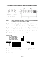
Cam Shaft Determination & Ordering Worksheet
Step 1
Decide whether the cam is a LEFT or a RIGHT hand and whether it
is a SMALL (3 3/32”) or LARGE (4 ¼”) head.
Step 2
Measure the length of the cam. It is best to provide both the
dimensions “A”, the distance from head to snap ring groove, and
dimension “B”, the distance from the head to the end of the cam.
Step 3
Measure the diameter of the cam at both “C”, just behind the head,
and “D” just inside the spline.
Step 4
Finally, determine whether the cam is a 10 spline or 28 tooth spline.
Please fill in the chart below when ordering a cam shaft
HEAD STYLE
LEFT HAND SMALL
RIGHT HAND SMALL
LEFT HAND LARGE
RIGHT HAND LARGE
DIMENSION
“A”
“B”
“C”
“D”
S P LI NE
10
28
Fax the completed worksheet to Eager Beaver Trailers @ 856-423-0999.
Your Name:
.
Your Voice Tel #:
.
Page 20
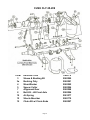
CUSH CLY-25-209
ITEM
3
3a
4
5
7
8
10
12
15
DESCRIPTION
Sleeve & Bushing Kit
Bushing Only
Wear Washer
Spacer Collar
Alignment Gear
Bolt Kit - LB Front Axle
Air Spring
Shock Absorber
Chain Kit w/ Clevis Ends
Page 21
PART #
2062280
2062281
2062282
2062284
2062288
2062286
2061077
2062170
2062287
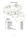
CUSH CLU-25-009
ITEM
1
4
5
6
7
9
11
14
DESCRIPTION
Bushing Only
Wear Washer
Spacer Collar
Alignment Gear
Bolt Kit
Air Spring
Shock Absorber
Chain Kit w/ Clevis Ends
Page 22
PART #
2062281
2062282
2062283
2062288
2062285
2061077
2062170
2062287
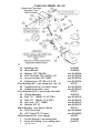
CUSH AIR LIFT MODEL CAL-01
APPLICATION
All 35-60 Ton Lowboys with Lift Axle
Used after 2003
Item
1
2
3
4
5
6
7
8
9
10
11
12
13
14
14a
14b
Parts List- Description
Hanger Sub-Assembly, 5" x-mber
Crank Sub-Assembly
Air Spring Pivot Sub-Assembly
Air Spring, Goodyear 2B12-440
Chain, 3/8 Grd P70 Transport (5 free links)
Clevis, Double-D, 3/8 Size
Bushing,
Urethane, 0.875 i.d.x 3.00 lg. Tube
.
Bushing, Urethane, 0.875 i.d.x 3.00 lg. Tube
Bush HHCS, 0.875-14UNF x 5 lg.
Bush Nut, NyLock, 0.875-14UNF
Pin, HHCS, 0.75 UNC x 6 lg.
Washer, Flat, 0.75 Size
Nut, Lock, 0.75 UNC, GR 5
KIT- Air Spring Mounting: 2B12-440
Flglock Nut, 0.50-13UNC, GR 2/5
Nylock Nut, Standard, 0.75-16UNF, GR 2/5
Part No.
SPECIAL ORDER
SPECIAL ORDER
SPECIAL ORDER
2062185
SPECIAL ORDER
SPECIAL ORDER
14b
SPECIAL ORDER
SPECIAL ORDER
SPECIAL ORDER
SPECIAL ORDER
SPECIAL ORDER
SPECIAL ORDER
SPECIAL ORDER
SPECIAL ORDER
SPECIAL ORDER
SPECIAL ORDER
14b
ANTI-SIEZE GREASE
Page 23
CUSH CUU-25B09L (Hi Lift)
ITEM DESCRIPTION
3a Bushing Only
3b Wear Washer
3c Washer .875" SAE ID
3d E-20 Torx Bolt .875"-9UNC x 10"
3e SecureLoc Nut .875"-9UNC
3f
Reducer fm 1.25" OD to 0.9" ID
Pivot Bushing Kit: 1 per swing arm (3a - 3f)
4a Alignment Gear, eccentric, outer
4b Alignment washer, inner
Pivot Alignment Kit: 1 per hanger (4a & 4b)
5a Shock Absorber
5b Bolt .75" - 10UNC x 3.35" GR 5
5c Bolt .75" - 10UNC x 9.5" GR 5
5d Nut, lock, .75" - 10UNC
5e Washer 3/4" ID
Shock Bolt Kit: 1 per Shock (5b-5e)
6a D-D Clevis Link
6b 3/8" Chain P70 (7 Links)
Chain Restraint Kit, 1 per hanger
7
Lift Air Spring (1 per swing arm)
8
Susp. Air Spring (1 per swing arm)
*
Special Order
Page 24
PART #
2062281
2062282
see Kit K0334
see Kit K0334
see Kit K0334
see Kit K0334
K0334 *
see Kit K0335
see Kit K0335
K0335 *
2062170
see Kit K0130
see Kit K0130
see Kit K0130
see Kit K0130
K0130 *
see Kit K0095
see Kit K0095
K0095*
2062186
2061077
Page 25
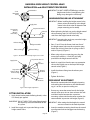
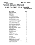
BARKSDALE RIDE HEIGHT CONTROL VALVE
INSTALLATION and ADJUSTMENT PROCEDURES
/4-20
Mounting
Studs
IMPORTANT: DO NOT OVERTIGHTEN fittings onto the
height control valve. Overtightening the
fittings may damage the valve body.
Part Number
1
C2
C1
VALVE MOUNTING/AIR LINE ATTACHMENT
Supply Port
Suspension Port C1
Suspension
Port C2
(Plug, If
Necessary)
Control
Arm
1. When tightening the lock nuts on the height control
valve mounting studs, DO NOT BACK OUT the
studs from the height control valve body.
IMPORTANT: Loosening the studs may cause the height
control valve to leak.
Exhaust Port
Exhaust Tube
IMPORTANT: Before installing the height control valve,
please review the drawings in the height
control valve kit in order to determine the
proper mounting and assembly.
Alignment Hole
2. Ports C1 and C2 on the forward and rear face of
the height control valve are the suspension ports.
Attach the air line(s) from the air springs to the C1
and/or C2 port(s) (Figure 1).
Exhaust Fitting
Figure 1. The Barksdale non-delay height control valve
Suspension Port C1
Supply Port
Fill
Position
3. When using only one suspension port, plug the
unused port with the 1/4 -inch NPT pipe plug
provided in the height control valve kit.
4. Attach air supply line from the pressure protection
valve to the supply port on the top of the height
control valve (Figure 1).
Raise
Suspension
Port C2 (Plug,
If Necessary)
Lower
Neutral
Position
5. Install the exhaust fitting into the exhaust port
(Figure 1).
6. Tighten all the lines.
Exhaust
Position
Exhaust Port
RIDE HEIGHT ADJUSTMENT
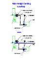
1. Determine recommended ride height by locating
and reading the information on the identification
tag; it is on the suspension trailing arm.
Figure 2. Ride height adjustment
1. Apply thread sealant onto the fitting threads, unless
it is already pre-applied.
2. If necessary, rotate the control arm for the height
control valve up to raise or down to lower the axle
until the distance between the suspension
mounting surface and the axle center matches the
recommended suspension ride height (Figure 2).
IMPORTANT: DO NOT APPLY TAPE to the fitting threads;
the tape may cause contamination of the
air system.
IMPORTANT: After setting the ride height, the control
arm must remain in the neutral position.
2. Install the supply and suspension fittings on the
height control valve.
3. Insert the wooden centering dowel into the control
arm alignment hole and engage into the housing
(Figure 1).
FITTING INSTALLATION
Page 26
Page 27
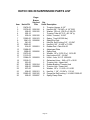
Page 28
HUTCH 900-50 SUSPENSION PARTS LIST
Item
1
2
3
4
5
7
8
9
10
12
13
14
15
16
17
18
19
20
21
22
23
24
25
Hutch PN
10476-03
10376-00
895-00
893-10
835-04
10055-00
9941-02
841-00
9293-00
814-00
10608-00
9938-00
10273-00
11513-03
10064-02
12919-01
891-00
890-00
892-00
837-00
836-00
10562-00
820-00
Eager
Beaver
Stocked
PNs
2058106
2058105
2058100
2058103
2058090
2058091
2058092
2058093
2058104
2058099
2058101
2060165
2058097
Qty
Used
2
4
2
1
4
2
4
4
8
8
4
4
8
8
8
2
2
2
2
8
8
16
2
Description
Trunnion Hanger, 4-1/2"
Hex Bolt 3/4" -16 UNF x 4 1/2" GR5
Washer, 7GA x 4 1/32 ID x 5 3/4 OD
Trunnion Tube (42" S.C.) 26-1/8" Ig
U-Bolt, Trunnion, 15-3/8"
Spring, 7 Leaf (50,000 Ibs.)
Spring End Cap
Hex Nut, Self Locking 3/4" - 16 UNF
Hex Bolt, 5/8" -18 UNF x 2" GR5
Rubber Pad - Plain 814-00
Adjustment Plate
Spring Seat
Washer, 1/8" x 21/32 ID x 1 15/16 0D
Hex Lockrrut 5/8" - 18 UNF
U-Bolt - Axle, 10-1/2" 10064-02
Galvanized Liner - .040 x 4.75 x 10.00
Trunnion Hub - Upper Half
Rubber Bushing, Trunnion Hub
Trunnion Hub - Lower Half
Washer, 1/8" x 1 1/4 ID x 2 1/4 OD
Hex Nut, 1 1/8" -12 UNF x 1 1/2 HI
Flange Nut Self Locking 1-14 UNS 10562-00
Spring Clamp Plate
Page 29
Page 30
Page 31
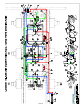
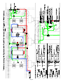
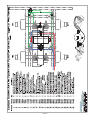
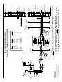
Lowboy Tri-Axle Air System with ABS, Dump Valve and Lift Axle
Item
1
2
3
4
5
6
7
8
9
10
11
12
13
14
15
16
17
18
19
20
21
22
23
24
25
26
27
28
29
30
31
32
33
34
35
36
37
38
39
40
41
42
43
44
45
Part
322071
322129
322132
322133
322135
322139
371503
371504
381031
381032
381041
381051
381052
381053
381101
381153
381203
381211
381302
381878
381879
381880
381881
381901
381902
381904
381910
382001
382002
382003
382106
382150
382151
382154
382156
382162
382163
382165
382171
382224
383121
391311
411101
411121
411301
Qty
1
1
2
2
1
1
1
1
4
6
6
3
1
1
2
2
2
2
2
60
45
30
10
6
4
2
2
5
10
3
10
1
2
2
2
8
2
2
1
1
1
1
2
8
2
Description
Comment
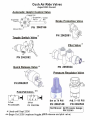
CUSH LWBY HT CONTROL VALVE KIT
PRESS REG VALVE,FIXED @ 70 PSI
TOGGLE CTRL VLV SEALCO#21600-2
AIR PILOT VLV - SEALCO #110591
QUICK REL VLV P/N 3800
BRAKE PROTECT VALVE #140270
3/8FNPT AIR/QD COUPLER
3/8FNPT AIR/QD NIPPLE
3/8T-3/8M STRAIGHT CONN (QCAB)
3/8T-1/4M STRAIGHT CONN (QCAB)
3/8TUBE UNION TEE
(QCAB)
3/8T-3/8M SWVL BRNCH TEE(QCAB)
3/8T-1/8M SWVL BRNCH TEE(QCAB)
3/8T-1/4M SWVL BRNCH TEE(QCAB)
3/8FPT3/8FPT BLKHD CUP (STEEL)
3/4"HD NIPPLE,SEALCO #6006
AIR TANK (2850)-CUSH, 2PORT
REMOTE DRAIN VLV (350002-048)
SPRING BRAKE VLV,SEALCO 110800
3/8OD NYLON BRAKE TUBING- RED
3/8OD NYLON BRAKE TUBING-BLUE
3/8OD NYLON BRAKE TUBING-GREEN
3/8OD NYLON TUBING (BLACK)
24" 3/8 AIR BRAKE HOSE ASSY
30" 3/8 AIR BRAKE HOSE ASSY
48" 3/8 AIR BRAKE HOSE ASSY
54" 3/8 AIR BRAKE HOSE ASSY
3/8T-1/4M SWVL 90 ELBOW (QCAB)
3/8T-3/8M SWVL 90 ELBOW (QCAB)
3/8T-1/8M SWVL 90 ELBOW (QCAB)
3/8 90°STRT ELBOW,BRASS,3400X6
3/8"HEX NIPPLE (BRASS)
1/4"HEX NIPPLE (BRASS)
3/8"X 1/4"HEX NIPPLE (BRASS)
1/2"X 3/4"HEX NIPPLE
3/8 SQHD PLUG
(BRASS)
3/4 HEXHD PLUG
(BRASS)
1/8 HEX SOCKET PLUG (BRASS)
1/4 HEX SOCKET PLUG (BRASS)
MOUNTED TEE'S (SEALCO)
1/4 NPT BRASS TEE,W/H 3700X4
ABS 2.5" AMBR MARKERLITE
(Not Shown)
1/4-20X2 ZN HXHD CPSCRW GR5
3/8-16X1.25 HEXHD CPSCRW GR5
1/4-20 NYLOCK
Page 32
28
Lowboy Tri-Axle Air System with ABS, Dump Valve and Lift Axle
Item
Part
46 411309
47 411321
48 411402
49 411471
50 411501
51 411503
52 411553
53 411626
54 411821
55 413002
56 413041
57 420001
58 423002
59 440041
60 440042
61 440043
62 445844
63 445845
64 445850
65 451007
66 451010
67 451022
68 451056
69 451020
70 451015
Qty
2
8
2
2
16
4
10
10
18
2
1
2
1
1
2
1
1
1
1
1
1
6
1
4
4
Description
5/16-18 HEXNUT ZN GR.2
3/8-16 NYLOC LOCKNUT
3/8 RBC CLAMP
1"SAE FLAT WASHER PLATED
3/8 STD FLAT WASHER,ZN
1/4"U.S.STD.FLAT WASHER,ZN
24" TIE WRAP #CT24HD
10-32X3/4 PANHD SCRW TYPE F ST
1/2ID HOSE SEPARATOR
5/16-20X2 1/2 TORXHD DECKSCREW
1/4X1.375" SAFETY SNAP PIN
AIRTANK MOUNTING PAD #1068
2.5"GROMMET PET#B142-18
"CAUTION TRLR EQPT W/ABS BRKS"
"ALL-WHEEL ABS"6.125X12.125
"ABS INDICATOR LAMP INSTRUCTN"
DECAL (LIFT AXLE)
DECAL (AIRBAG EXHAUST)
DECAL -DANGER,SPRING BRAKES
4005001030 (2&3 AXLE ECU),ESII
472-195-033-0 RELAY VALVE
4497130180 6' SENSOR EXT CBLE
4494410300 10' RELAY CABLE,ESII
4410328080 SENSOR W 1' CABLE
8997598154 SENSOR RETAINER CLIP
Page 33
Comment
(Not Shown)
(Not Shown)
(Not Shown)
(Not Shown)
(Not Shown)
(Not Shown)
(Not Shown)
(Not Shown)
(Not Shown)
(Not Shown)
(Not Shown)
(Not Shown)
(Not Shown)
(Not Shown)
Page 34
Page 35
Page 36
2
2
PULLED OUT
1
PUSHED IN
1
5
PULLED OUT
1 5
3
PUSHED IN
4
1
4
2
3
2
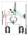
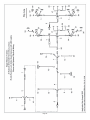
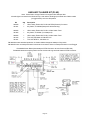
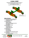
3rd Axle Lift/Dump Valve
3
3
LIFT VALVE
Description
Dump Valve
Air Bags
Exhaust
Lift Bag
Supply
LIFT VALVE
Description
Dump Valve
Air Bags
Exhaust
Lift Bag
Supply
PORT No
3
2
1
4
5
PORT No
3
2
1
4
5
Connected
Connected
Blocked
(5) Port x (2) Position
3rd Axle Air Bags are
Exhausted
Air Flows from Supply to Lift
Air Bag
- Knob OUT
Lift Air Bags is Exhausted
Connected
Blocked
Air Flows from Dump Valve
to 3rd Axle Air Bags
- Knob IN
Connected
(5) Port x (2) Position
DUMP VALVE (3) Port x (2) Position - Knob OUT
Description
Blocked
HCV
Air Flows from Air Bags out
Air Bags
Connected
of Exhaust
Exhaust
PORT No
1
2
3
(p/n 322128)
DUMP VALVE (3) Port x (2) Position - Knob IN
Description
Air Flows from HCV to Air
HCV
Connected
Bags
Air Bags
Blocked
Exhaust
PORT No
1
2
3
(p/n 322130)
5
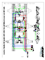
Controls Manual Raise & Lower Valve
for 3rd Axle Lift
Manual Raise and Lower Valve
Air Gauge
4
1st & 2nd Axle Dump Valve
1
BU1
3
2
3
1
2
4
1
5
10
0
2
10
3
1
20
90
2
30
80
3
40
70
BU2
Air Gauge
Manual Raise and Lower Valve
Supply from Tank
70 psi Regulator
from Dump Valve
to Lift Axle Lift Bag
to Lift Axle Main Air Bags
for 3rd Axle Lift
Exhaust Breather
from HCV
from Manual Raise & Lower Vlave
Controls Manual Raise & Lower Valve
to ALL Main Air Bags
to Non-Lift Axle Main Air Bags
Tri-Axle Lowboy Air System with Push/Pull Valves ( NO Pilot Valves) and Manual Raise & Lower
50
60
Page 37
Page 38
Page 39
Page 40
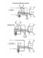
LIFT AIR BAG
EXHAUST
EXHAUST
TOGGLE SWITCH
(p/n 21600-2)
HEIGHT CONTROL VALVE
MAIN AIR BAG
BRAKE PROTECTION VALVE
SUPPLY
CONTROL
QUICK RELEASE VALVE
(p/n 3800)
Applicable to Lowboy Trailers with Toggle Control Switch
(manufactured before October 2006)
LIFT AXLE AIR SYSTEM
REMOVABLE AXLE OPERATING INSTRUCTIONS
Removable Axle ONLY Install
When the Removable Axle is close coupled to the trailer, simply connect the bottom and top
pins, bottom pins first. If equipped, u se the Manual over ride controls on the Removable Axle
to raise or lower the Removable Axle until the upper pins can be inserted.
Attach ALL air and electrical connections . See the final Check List at the end of this document
for removable axle operational notes.
WARNING!
Make sure that the manual over ride control are turned OFF before
moving trailer. To turn off the manual override control, push in the knob labeled PULL TO
TURN ON MANUAL OVERRIDE. See label to right.
Removable Axle and Nitro-Booster Install
When the Removable Axle is used with a Nitro-Spreader Bar, simply connect the bottom and
top pins of both the spreader bar and the Removable Axle, bottom pins first. Using the manual
raise and lower controls for both the trailer and Removable Axle, as well the jack on the NitroSpreader bar can facilitate this connecting procedure. See the operational instruction decal on
the Nitro-Spreader Bar for detail instructions of its use.
WARNING!
The Nitro-Spreader bar is for use with ONE Removable Axle ONLY. Using
more than one Removable Axle can damage the Nitro-Spreader bar.
WARNING!
Make sure that the manual over ride controls on the trailer and Removable
Axle are turned OFF before moving trailer.
Removable Axle and East Coast Spreader Install
When the Removable Axle is used with an East Coast Spreader Bar, a shimming process is
required to transfer the proper weight to the Removable Axle.
Install the bottom pins only of both the spreader bar and the Removable Axle. DO NOT install
the top pins. Connect SUPPLY RED air line. This will allow the use of the Removable Axle’s
manual override controls to raise and lower the Removable Axle. Install equal amounts of
Shims at the spreader to trailer connection as are used at the Removable Axle to spreader
connection. Make sure that the shims on each side of the trailer are always the same. Use the
Manual Override controls on both the trailer and Removable Axle to raise or lower the trailer
rear and the Removable Axle until the proper amount of shims can be inserted. This is usually
achieved by raising the trailer rear and lowering the Removable Axle.
Page 41
Changing the shim thickness may need to be done several times until ALL the axle loads are
equal. Checking axle loads requires a certified scale.
CAUTION!
Confirmation of axle loads should only be checked at Certified Scales.
Unequal axle loads can damage the trailer frame or suspensions.
WARNING!
moving trailer.
Make sure that the any manual over ride control are turned OFF before
Removable Axle Operation Check List
•
Make sure that the electrical plugs are firmly inserted and locked into the electrical
socket at the rear of the trailer and spreader bar, if installed. Check ALL Lights for
proper operation (Stop/Tail/Turn, Marker, Clearance and Strobe or Back-Up Lights (if
equipped)).
•
Make sure that all Air Lines are connected at both the rear of the trailer and spreader
bar, if installed. Check that the Air Brake will apply and release. Removable Axles do
NOT have the ABS function. The brake application is independent of the trailer brakes
and receives it supply (Emergency Line) and control (Service Line) directly from the
tractor. See chart below for air connection labeling.
Decal Image
RED SUPPLY (Emergency) air line from tractor.
BLUE Control (Service) air line from tractor.
Supply line from trailer tank brake protection valve.
Air Ride Supply air from trailer Automatic Height Control Valve.
•
The air suspensions air supply comes from the trailers Automatic Height Control Valve
(HCV), so the ride height should be the same as the trailers axles when loaded. The
Removable Axle should NOT be used when traveling empty or minimal load. The
Removable Axle can be complete removed or flipped over onto the trailer for storage.
WARNING!
Make sure that the manual over ride control are turned OFF and
back to automatic before moving the trailer. Failure to do so may damage either the
trailer frame or suspensions.
Page 42
Page 43
3. Push in the Push-Push air control valve on the +1 axle to engage automatic ride height control. Scale load with 3+1
axle configuration. Make final shim adjustments to achieve 25% load distribution goal. In essence, add shims to
increase weight distribution to the +1 axle; remove shims to decrease the weight distribution to the +1 axle.
2. With a load on the trailer, add or remove shims as necessary between trailer & spreader and between spreader & the
+1 spread axle to make top of trunnion beam over trailer axle almost level with top of beam on spread axle (see
Reference Point A & B, respectively, in above diagram). Use the manual raise - lower valve on both trailer (if installed)
and spread axle as a tool to raise & lower rear of trailer and spread axle to assist with adding shims. In order to achieve
separation between the spreader and +1 axle, blocking may need to be placed under the rear of the spreader in
conjunction with dumping the air from the +1 axle suspension.
1. With a load on the trailer, scale 3 trailer axles. To do this, either remove the spreader or remove all shims and dump
spread axle air to ensure negligible weight distributed to spread axle. Record the scale weight of the three trailer axles.
Goal will be to distribute 25% of this weight to spread axle. For example, if 3 axles scale at 78,000 lbs, goal will be to
distribute 19,500 lbs to the spread axle, thereby reducing the weight on the 3 trailer axles from 78,000 to 58,500.
Universal Spread Axle Shimming and Trailer Scaling Recommendations
Page 44
Air Supplied from Trailer Tank
Brake Protection Valve
Air Supplied from
Trailer ECU (BU1 port)
Air Supplied from
Trailer ECU (YE1 port)
Air Supplied from Trailer
Height Control Valve (HCV)
2
3
1
4
5
5
PULLED OUT
1 5
3
PUSHED IN
4
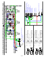
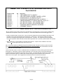
LIFT VALVE
Description
Dump Valve
Air Bags
Exhaust
Lift Bag
Supply
LIFT VALVE
Description
Dump Valve
Air Bags
Exhaust
Lift Bag
Supply
PORT No
3
2
1
4
5
PORT No
3
2
1
4
5
(p/n 322128)
Supply from Tank
70 psi Regulator
from Trailer HCV Valve
Exhaust Breather
for Flip Axle Lift
to Flip Axle Air Bags
4
1
(Note: Additional bulkhead and Quick Disconnect required)
to Lift Air Bag
2
3
BRAKES
YE1
AIR RIDE
Connected
Connected
Blocked
(5) Port x (2) Position
3rd Axle Air Bags are
Exhausted
Air Flows from Supply to Lift
Air Bag
- Knob OUT
Lift Air Bags is Exhausted
Connected
Blocked
Connected
- Knob IN
Air Flows from Dump Valve
to 3rd Axle Air Bags
(5) Port x (2) Position
Trailer Tailboard Modification for Flip
3rd Axle Lift/Dump Valve
2
BRAKES
BU1
Trailer Push-Pull Valve Holes
New 1-1/8" Ø Hole for Flip Lift Air Supply
Flip with Lift Air System with Push/Pull Valves
Page 45
Air Supplied from
Trailer ECU (BU1 port)
Air Supplied from
Trailer ECU (YE1 port)
Air Supplied from Trailer
Height Control Valve (HCV)
BRAKES
BU1
221
221
10
33
4
10
334
221
BRAKES
YE1
AIR RIDE
Trailer Push-Pull Valve Holes
Trailer Tailboard Modification for Flip
Flip Air System
Page 46
Page 47
No Bolt Style
with Shims
Begin
Dec 2005
2063091
2063093
NA
NA
NA
987135
413042
413043
Standard Flip 4th Axle Pins (Not for use with Universal)
Upper Flip Pin - 1.5" Dia x 4" Long
Lower Flip Pin - 2" Dia x 7" Long
Snap Pin to secure upper & lower pins (1 per pin)
All Models
Before Dec 2007
2063091
2063092
413042
Beginning in December 2007 Universal Booster Flip used on All Lowboys
Standard Flip 4th Axle ONLY (Pre Universal)
Booster and Universal Flip Axle Pins & Shims
Upper Pin - 1.5" Dia x 4" Long
Lower Pin - 2.5" Dia x 10" Long
Universal Flip Upper Pin - 1.75" Dia x 9" Long (includes snap pins)
Universal Flip & 1 Axle Spreader Lower Pin - 2" Dia x 9 " Long (incl. snap pins)
Universal Flip & 2 Axle Spreader Lower Pin - 2.5" Dia x 10" Long (incl. snap pins)
Shim Kit
Snap Pin to secure Upper Pin (2 of PN 413043 or 1 of PN 413042 per pin)
Snap Pin to secure Lower Pin (2 per pin required)
Bolt Style
"No Shim"
Until
Nov 2005
2063091
2063093
NA
NA
NA
NA
413042
413043
Booster 4th Axle & Flip 4th Axle Pins
Universal
with Shims
Begin
Dec 2007
NA
NA
2063095
2063094
2063093
987175
413043
413043
Page 48
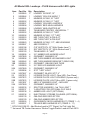
All Model GSL Lowboys - PLUS Harness with LED Lights
Item
1
2
3
4
5
6
7
8
9
10
11
12
13
14
15
16
17
18
18A
19
19A
19B
20
20A
21
21A
22
22A
22B
23
23A
24
25
26
27
Part No. Qty Description
2062045
2
LOWBOY SOCKET,12"
2062046
1
LOWBOY GSL G/N MAIN,11'
2062251
1
MARKER,2-POLE,19" "LED"
2062252
1
MARKER,2-POLE,51" "LED"
2062057
1
LOWBOY GSL BED JUMPER,6'
2062058
1
LOWBOY BED MAIN HARNESS
2062068
1
LOWBOY ABS ADAPTER,84"
2062061
1
TAILBOARD CENTER, UNIVERSAL **
2062252
1
MARKER,2-POLE,51" "LED"
2062256
1
MARKER,2-POLE,117" "LED"
2062253
1
MID TURN,"LED",4-POLE,47"
2062254
1
MID TURN,"LED",4-POLE,80"
2052063
1
MARKER,2-POLE,117", ABS WARNING
2062067
1
ABS POWER,41"
2062198
1
C/S "LED"PGTL,10" (With Strobe Lead *)
2062199
1
S/S "LED"PGTL,10" (With Strobe Lead *)
2062193
1
TAILBOARD I.D.,"LED"
2062095
4
2.5" AMBER LED MARKER LIGHT
2057069
4
GROMMET, MARKER 2.5"
2062096
2
MID TURN AMBER LED MARKER LIGHT
2062242
2
MID TURN MARKER BRACKET (WELD ON)
2062243
2
GROMMET, OBLONG MID TURN
2062093
5
2.5" RED LED MARKER LIGHT
2057069
5
GROMMET, MARKER 2.5"
2062094
4
S/T/T "LED" LIGHT
2057067
4
GROMMET, BLACK S/T/T 4"
2057075 1
LICENSE PLATE LIGHT (Non LED, One-Piece)
2057072 1
LICENSE PLATE LIGHT HOUSING (2-piece only)
2057074 1
LICENSE PLATE LIGHT (Non LED, 2-piece only)
2061097
1
ABS 2.5" MARKER LIGHT - NON LED
2057069
1
GROMMET, MARKER 2.5"
2062335
2
SPLITTER HARNESS - 3rd TAIL LIGHT *
2062337
1
Y ADAPTER FOR OPTIONAL FLIP AXLE
2062338
2
AMBER LED LIGHT (OPTIONAL)
2062336
2
ELECTRONIC STROBE FLASHER (OPTIONAL)
2062130
2
OBLONG RED REFLECTOR
2062129
6
OBLONG AMBER REFLECTOR
KIT
2062255
1
GOOSENECK NECK HARNESS KIT (ITEMS 1 - 4)
KIT
2062257
1
TRAILER BED HARNESS KIT (ITEMS 5 - 17)
* ECN 1604 2/26/10 - Add Strobe Lead to STT Pigtail; 3rd Tail Light Std
** Universal TB Center Harness w/ Strobe Toggle Switch Lead std Feb 2010
Page 49
Page 50
, 14893 Hiighway 27, Lake Wales, Florida, USA, 33859,
1-800-257-8163
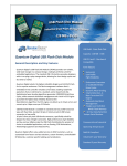
7-WAY
TRACTOR
PLUG
This drawing and specifications are the property of General Engines Co., Inc. dba Eager Beaver Trailers
shall not be reproduced, copied or used in any fashion without express written permission. Also, General
Engines Co., Inc. reserves the right to change designs, specification or materials without notice and
without incurring any obligation to such changes.
General Engines Co., Inc.
WHITE
BROWN
RED
IGNITION
SWITCH
BLUE
YELLOW
GREEN
Page 51
+
BLACK
STOP LIGHT
SWITCH
-
WHITE
BROWN
YELLOW
RED
GREEN
BLUE
BATTERY
10
Stop, ABS
Strobe Circuit
Charging, ABS
Red
Black
Blue
BLUE
BLACK
PLUG
YELLOW
RED
PLUG LOAD VIEW
(7-WAY)
BLACK
WHITE
BROWN
YELLOW
RED
GREEN
YELLOW
RED
BLUE
14
14
BLUE
BED FRONT
CLEARANCE
BED FRONT
CLEARANCE
MID TURN
MID TURN
ABS
ECU
TAILBOARD for STROBES
with SWITCH on TRAILER
TAILBOARD for STROBES
with SWITCH in TRACTOR
LEFT TURN
CLEARANCE
STROBE FLASHER
STOP
TAIL
STROBE
Acc Plug
LICENSE
I. D. LIGHTS
STROBE FLASHER
STROBE
STOP
TAIL
RIGHT TURN
CLEARANCE
LEFT TURN
CLEARANCE
STROBE FLASHER
STOP
TAIL
STROBE
LICENSE
STROBE SWITCH
Acc Plug
I. D. LIGHTS
STROBE FLASHER
STROBE
STOP
TAIL
RIGHT TURN
CLEARANCE
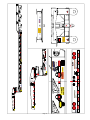
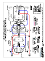
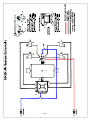
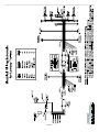
Notes: The Black wire is NOT normally used on trailers with ABS air brakes, but can be used
for Trailers with Back-UP Lights, Strobe Lights or for Auxiliary Power.
The White ground wire on the truck should be a good solid ground.
The Blue ABS wire on the truck should be keyed to the ignition and fused, 20-amp.
The Red stop light wire on the truck should be connected to the stop light switch.
FRONT SIDE
CLEARANCE
GREEN
WHITE
BROWN
SOCKET
SOCKET LOAD VIEW
GREEN
BROWN
BLACK
10
Tail Lights
Brown
WHITE
10
Left Turn
Yellow
FRONT SIDE
CLEARANCE
14
Right Turn
Green
8
Ground
White
Gauge
Function
Color
Electrical Wiring Schematic
for Lowboy Trailers with Strobe Lights
AUXILARY FLASHER KIT (PLUS)
Note: Power feed to charge Flasher is through the Blue Harness Wire
All trailer lights connected to the Brown wire (ie, side markers & tail lights) will Flash when flasher switch
(or toggle switch) are in the ON position
PN
999406
391921
Qty
1
1
999405
391905
1
1
USA-Lowboy Flasher Kit, PLUS w 2 Wire Switch Feed
Key Switch, CH M489 (non-waterproof)
999405
391915
391931
1
1
1
USA-Lowboy Flasher Kit, PLUS w 2 Wire Switch Feed
TGL SWT,CH #5582-10 ON-OFF PVC
TGL SWT MTG PL, CH #5543-15
Description
USA-Lowboy Flasher Kit, PLUS with DT06 (Deutsch) Connector
Key Switch, CH 95060 (waterproof with booted key)
PN 999406 became standard production in October 2008 and supports waterproof key switch
PN 999405 has a non-waterproof switch harness and connects to either non-waterproof switch or on/off toggle
PN 999406 Shown Below (Note waterproof DT06 Connector at end of harness GEN-185)
PN 999405 identical except key switch line has 2-wires with ring terminals instead of DT06 connector
Page 52
AMBER "LED" STROBE LITE ON TAILBOARD ADD-ON KIT
Part # 2063158
Component PN
Qty
Description
2062338
2062336
2057537
2057538
2057539
2062198 **
2062199 **
2062061 **
2057067
2
2
1
1
1
1
1
1
2
"LED" AMBER LIGHT, TL #44871Y
"LED" ELECTRONIC STROBE FLASHER, # 97253
TOGGLE SWITCH, CH #5582-10 ON-OFF *
TOGGLE SWITCH MOUNTING PLATE, CH #5543-1 *
T/BOARD HARNESS-TO-TOGGLE SWITCH, 2 Pole, 24" *
C/S "LED" STT PIGTAIL, WITH STROBE LEAD **
S/S "LED" STT PIGTAIL, WITH STROBE LEAD
TAILBOARD CENTER HARNESS, UNIVERSAL *
4"GROMMET B426-18
2057540
1
JUMPER, BLACK CIRCUIT, T/BRD CENTER HARNESS, UNIV ***
* May be omitted from Kit if Strobe On/Off to be controlled ONLY via switchd power in the tow vehicle (via Black Wire).
Asterik items are required in order to have a remote (i.e., on the trailer) tailboard mounted On/Off toggle control.
** Trailers manufactured after January 2010, may have Universal Tailboard Harness (PN 2062061) with Strobe Lead
and black circuit jumper (PN 2057540) on the Strobe lead. Between Feb - April 2010 C/S & S/S STT Pigtails
phased out and replaced with Pigtails that include Strobe lead. Therefore, new Tailboard Harness and Pigtails
may not be required for Strobe Lite Add-on Kit for trailers mfg between Feb - April 2010. (Subtract $160 if not required)
*** Not Included in Kit. Comes installed on Universal Center Harness. Jumper must be installed to close circuit
if there is no On/Off toggle switch being used to close circuit.
Note: Kit contains replacement tailboard wiring with the additional leads and switch necessary to power the strobe
lights. Power to the Strobe lights is supplied via the black wire in the nose harness. This lead should be connected
to a power source on the tow vehicle.
Customer will either need to cut two 4.5” Diameter holes in the Tailboard to mount the rubber grommets and amber
strobe lights or, manufacture a weld-on surface bracket with a 4.5” Dia. Hole in which to mount the strobe light.
A small hole through the tailboard for the strobe wires is required. For trailers Mfg after Feb 2010 with a 3rd Tail light,
replace the 3rd Red STT light & "Y" Splitter with an amber LED Light & Electronic Flasher and connect to the
Strobe Lead on STT Pigtail. Order Toggle Switch and Switch Harness for optional remote On/Off.
Page 53
Eager Beaver Trailers 35 - 60 Ton Lowboy
Miscellaneous Parts List
PART NO.
2054869
2059133
2059134
2060659
2058065
2062129
2062130
2060735
2063020
2054792
2061023
2061024
2061025
2061026
2062175
2062176
425001
DESCRIPTION
Deck Washer
Hex Head Bolt, Deck Washer, 3/8 x 2 1/2
Nut, Deck Washer, 3/8-16
Truck Wiring Harness
Air Tank Remote Drain Valve
Oblong Reflector - Amber
Oblong Reflector - Red
Eager Beaver Trailers Mud Flap - White 24" x 18"
Roto-Ring® Assembly
Weld-on HD Fixed D-Ring & Clip
Air Fitting, Nipple, 3/8 Male NPT
Air Fitting, Coupler, 3/8 Male NPT
Air Fitting, Coupler, 3/8 Female NPT
Air Fitting, Nipple, 3/8 Female NPT
Cast Steel Outrigger
Cast Steel Outrigger Bracket
Gooseneck Lube System Access Hole Cover
Eager Beaver
Standard Colors
Manufactured After
8/6/10
Dupont Imron
MFG between 9/22/06
and 8/6/10
PPG Color Code
Yellow
Red
Black
Blue
White
H7947
77968
1640
3759
1632
FP827
FP703
FP901
*
FP951
* Custom Mixed Color, No Code Assigned
Page 54
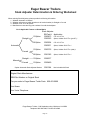
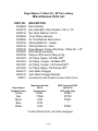
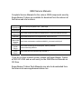
OEM Service Manuals
Complete Service Manuals for the various OEM components used by
Eager Beaver Trailers are available for download from the internet at
the below web site locations.
Cush
Suspensions
Hutch 900
Suspension
Hutch 9700
Suspension
Hendrickson
D22 Axle
Meritor
Wabco ABS
(Premium
ECU)
Honda
GX390
Engine
Hatz 1B40
Diesel
Engine
http://cushcorp.com/pdfs/P1203-1_Manual.pdf
http://www.hutchensindustries.com/pdfs/ssLib_900.pdf
http://www.hutchensindustries.com/pdfs/resource_suspensionMaintenance.pdf
http://www.hendrickson-intl.com/pdfs/trailer_PDFs/L1061.pdf
http://www.meritorwabco.com/MeritorWABCO_document/mm0180.pdf
http://www.honda-engines.com/Engines_owners_manuals/
ownersmanuals/gx390.htm
http://www.hatz-diesel.de/index.php?id=50&L=1
If you do not have internet access, please call Eager Beaver Trailers
at 800-257-8163 and we will send you the OEM Service Manuals on
CD Rom.
Eager Beaver Trailers Parts Manuals may also be downloaded from
the internet at www.eagerbeavertrailers.com