1
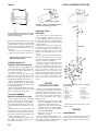
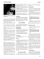
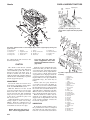
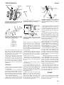
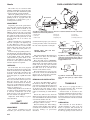
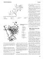
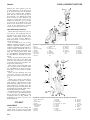
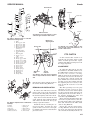
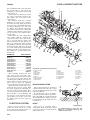
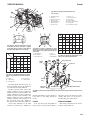
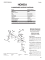
SERVICE MANUAL
Honda
HONDA
CONDENSED SPECIFICATIONS
Models
HT3813, HT4213
Engine Make
Model
Number of cylinders
Bore
Stroke
Displacement
Power Rating
Slow Idle
High Speed (No-Load)
Crankcase Capacity
Transaxle Capacity
Coolant Capacity
Honda
GX360
2
58 mm (2.28 in.)
68 mm (2.68 in.)
359 cc (21.9 cu. in.)
9.7 kW (13 hp.)
1300 rpm
3300 rpm
1.4 L* (1.5 qt.)
2.9 L (3.1 qt.)
1.35 L (1.4 qt.)
*If installing new filter, check oil level after running engine for a few minutes.
NOTE: Honda special tools may
be required for some procedures and are indicated in the
text. Read the text completely
before attempting procedure.
FRONT AXLE AND
STEERING SYSTEM
MAINTENANCE
Lubricate the steering spindles annually or after 100 hours of operation.
Inject multipurpose grease into the
grease fittings at the axle’s outer ends.
Clean the grease fittings before and after lubrication.
FRONT WHEELS AND BEARINGS
Each front wheel is supported by two
sealed ball bearings not requiring periodic lubrication.
Replace the bearings if they are loose
or do not spin smoothly. Tighten the
bearing retaining nut to 55-65 N·m
(40-47 ft.-lb.). Secure the nut with a cotter pin.
TIE ROD AND TOE-IN
Fig. HN1-1—Exploded view of front axle assembly.
1. Spindle (left)
2. Bushing
3. Axle main member
4. Tie rod
5. Washer
6. Bolt
7. Steering lever
8. Drag link
9. Bolt
10. Snap ring
11. Spindle (right)
The tie rod (4—Fig. HN1-1) is
equipped with threaded ends at each
end. Replace the tie rod if the ends are
damaged.
The recommended front wheel toe-in
is 6-14 mm (0.24-0.55 in.). Measure the
209
Honda
YARD & GARDEN TRACTORS
Punch marks
Punch marks
Spindle
Fig. HN1-3—Align punch marks on steering
lever and spindle during assembly.
Fig. HN1-2—Measure distance “A” and “B”
at front and rear of front wheels to determine front wheel toe-in.
distance (A—Fig. HN1-2) between the
front of the front wheels at hub height
and the distance (B) between the rear of
the front wheels. The front distance (A)
should be smaller than the rear distance (B).
To adjust toe-in, loosen the locknut at
each tie rod end and rotate the tie rod.
NOTE: Left tie rod end and nut
have left-hand threads.
STEERING SPINDLES
REMOVAL AND INSTALLATION
To remove the steering spindle, raise
and support the front of the tractor. Remove the front wheel. Disconnect tie
rod end from spindle.
To remove the left spindle (1—Fig.
HN1-1), remove the clamp bolt (6) and
detach the steering arm (7) from the
spindle. Slide spindle out of the axle.
When installing the steering lever,
align the punch mark on the spindle
end with the punch mark on the steering arm (Fig. HN1-3).
To remove the right spindle (11—Fig.
HN1-1), detach the snap ring (10) and
slide the spindle out of the axle.
AXLE MAIN MEMBER
REMOVAL AND INSTALLATION
The complete front axle assembly
may be removed as a unit. To remove
the axle main member (3—Fig. HN1-1),
raise and support the front of the tractor. Disconnect the drag link’s (8) outer
end.
Support the axle main member and
remove the axle retaining bolt (9).
Lower the axle main member from the
mainframe pivot point and roll the axle
out from under the tractor.
When installing the axle main member, tighten the axle retaining bolt to
45-55 N·m (33-40 ft.-lb.).
210
STEERING GEAR
OVERHAUL
To remove the steering shaft and
gear assembly, remove the cover
(1—Fig. HN1-4) and nut (2). Remove
the steering wheel (3) and flat washer
(4). Disconnect the drag link end and
steering arm (15).
Remove the cap screws retaining the
steering plate (8). Remove the three cap
screws retaining the steering gear
holder (17). Remove the nut (11) and
pull the steering shaft (6) out of the
tractor.
Remove the gear (9) and washer (10).
Remove the steering gear (14) and
washers (13 and 16). Replace the bushings (5, 7 and 12) as required.
Reverse the removal procedure for
reassembly. Make certain the front
wheels are straight ahead, the larger
opening in the steering wheel is toward
the top and the steering gears are
meshed in the center of the gear (14)
during reassembly. Tighten the three
bolts retaining the steering gear holder
(17) to 23-30 N·m (17-22 ft.-lb.) and
nuts (2 and 11) to 45-54 N·m (33-40
ft.-lb.).
SAFETY
INTERLOCK SYSTEM
The tractor is equipped with switches
and relays preventing inadvertent
starting of the tractor engine or operation if the operator leaves the tractor
seat. The tractor engine should not
start if the following occurs (engage
parking brake):
• Operator in the tractor seat, shift
lever in NEUTRAL and the PTO
clutch lever in the ON position.
• Operator in the tractor seat, PTO
clutch lever in the OFF position
and the shift lever in a position
other than NEUTRAL.
• Operator not in the seat when
starting the engine.
The seat switch should kill the engine if the operator is not in the seat or
leaves the seat when the PTO clutch is
engaged or the tractor is in gear.
Fig. HN1-4—Exploded view of steering
gear assembly.
1.
2.
3.
4.
5.
6.
7.
8.
9.
Cover
Nut
Steering wheel
Washer
Bushing
Steering shaft
Bushing
Steering plate
Gear
10.
11.
12.
13.
14.
15.
16.
17.
Washer
Nut
Bushing
Washer
Sector gear
Steering arm
Washer
Steering gear
holder
Refer to the wiring schematics at end
of this section.
ENGINE
MAINTENANCE
The engine is equipped with a dry air
filter that should be cleaned and inspected after every 50 hours of operation.
SERVICE MANUAL
Fig. HN1-5—To bleed cooling system, open
air bleed screw (S) and proceed as described in text.
Remove the foam and paper air filter
elements from the air filter housing.
Wash the foam element in a mild detergent and water solution. Rinse in clean
water and allow to air dry.
After the foam element is dry, soak it
in clean engine oil. Squeeze out excess
oil.
Paper element may be cleaned by directing low pressure compressed air
stream from inside the filter toward the
outside.
Replace the paper element if it cannot be cleaned satisfactorily, or if it is
damaged.
The engine oil level should be
checked prior to operating engine.
Check the oil level with the oil cap not
screwed in, but just touching the opening’s threads.
Oil should be changed after the first
20 hours of engine operation and after
every 100 hours thereafter. Change the
oil filter after every 300 hours of operation or after two years.
Use oil meeting the latest API service
classification. Use SAE 10W-30 or
10W-40 oil; use SAE 10W-40 if the temperature is above 90°F (32°C).
Crankcase capacity is 1.4 liters (1.5
qt.).
REMOVAL AND INSTALLATION
Raise the hood and disconnect the
battery cables. Disconnect the headlight wiring connector and remove bolt
from the ground lead. Remove the hood
hinge bolts and remove the hood.
Drain the coolant. Detach the radiator hoses and remove the radiator.
Loosen the PTO belt tension knob and
remove the mower drive belt.
Detach the engine ground cable from
the front frame crossmember. Disconnect the throttle cable. Disconnect the
fuel hoses.
Disconnect the wiring from the starting motor, charge coil and ignition coil.
Honda
Remove regulator/rectifier bracket assembly from the engine. Separate the
wiring from the engine.
Remove the cooling fan. Remove the
PTO clutch as described in the PTO
CLUTCH section. Detach the PTO cable from the brackets.
Remove the engine mounting bolts
and nuts. Lift the engine and move it
forward to separate the engine from the
drive shaft and remove it from the tractor.
Reverse the removal procedure to install engine. Tighten front engine retaining nuts to 35-40 N·m (26-29 ft.-lb.).
stat, are covered in the appropriate
Honda engine section at rear of this
manual.
MAINTENANCE
Maintain the coolant level between
the reservoir tank’s MIN and MAX
marks. The recommended coolant is a
50:50 mixture of clean water and permanent antifreeze.
Periodically clean debris from the radiator screen. Periodically inspect coolant hoses between the radiator and
engine water pump. Replace damaged
hoses.
OVERHAUL
Engine make and model are listed in
specifications table at the beginning of
this section. Refer to the appropriate
Honda engine section in this manual
for service information on the engine
and associated accessories.
FUEL SYSTEM
Refer to ENGINE and ELECTRICAL
SYSTEM sections for fuel system related components not covered here.
FUEL FILTER
MAINTENANCE
A fuel filter is located in the fuel line
between the fuel tank and the fuel
pump. The fuel filter is visible through
a hole in the rear hitch plate.
Inspect the fuel filter annually or after every 100 hours of operation. Replace the filter if it is dirty or damaged.
FUEL PUMP
The fuel pump is located on a bracket
below the fuel tank.
Testing
Before testing the fuel pump be sure
the fuel filter and fuel line are in good
condition and the fuel flow to the pump
is unimpeded.
Connect a suitable pressure gauge to
the fuel pump output port. Turn the ignition switch ON, but do not start the
engine. Fuel pump pressure should be
6.9-14.2 kPa (1.0-2.0 psi).
Direct a hose from pump output port
into a container. Turn the ignition
switch ON, but do not start the engine.
Fuel pump volume should be at least
350 cc (11.8 oz.) during one minute of
operation.
COOLING SYSTEM
Cooling components on the engine,
such as the water pump and thermo-
WARNING: Coolant in the system is pressurized. Remove the
pressure cap only when engine
is cold.
Change the coolant at least every two
years. Flush the cooling system at least
every three years. Coolant system capacity is approximately 1.35 liters (1.4
qt.).
CHANGE COOLANT
Remove the engine’s pressure cap
(C–Fig. HN1-5). Drain coolant by opening radiator drain valve.
WARNING: Coolant in the radiator is pressurized. Remove pressure cap only when the engine is
cold.
Empty the reservoir tank. Close the
radiator drain valve. Open the air bleed
screw (S—Fig. HN1-5). Refill with a
50:50 mixture of clean water and permanent antifreeze. Pour coolant into
the fill hole until air-free coolant runs
out of bleed screw hole, then reinstall
the bleed screw.
Position the pressure cap on the filler
neck, but do not tighten the cap. Run
the engine until the upper radiator
hose becomes warm. Stop the engine
and add coolant through the filler neck
as needed. Install and tighten the pressure cap.
Fill the reservoir tank with coolant to
proper level. Run the engine, while
monitoring the engine temperature to
be sure the engine does not overheat.
Allow the engine to cool and recheck the
coolant level.
HOSE ROUTING
The left radiator hose connects to the
thermostat housing. The right radiator
hose connects to a spigot on the right
side of the cylinder block. Bypass hose
attaches to a spigot at the right rear of
211
Honda
YARD & GARDEN TRACTORS
Shift
lever
Clutch arm
Adjusting nuts
Shift
gear
plate
0.5-1.0 mm
(0.02-0.04 in.)
Fig. HN1-7—Turn adjusting nuts at end of
clutch cable to adjust cable free play. Refer
to text.
Fig. HN1-6—Exploded view of clutch linkage. Adjust clutch rod (2) length by turning nuts
(1) at rod end.
1.
2.
3.
4.
Adjusting nuts
Clutch rod
Clutch cable
Damper arm
5.
6.
7.
8.
Damper
Adjustment bolt
Damper spring
Clutch arm
the cylinder block and connects to the
thermostat housing.
CLUTCH
The clutch is a disc that is actuated
by linkage connected to the shift lever
and clutch/brake pedal. The clutch is
disengaged when the shift lever is
moved to another slot or the brake is
applied. A hydraulic cylinder (damper)
attached to the clutch linkage regulates
clutch engagement speed.
ADJUSTMENT
Be sure the clutch is not worn excessively before attempting clutch adjustment. See INSPECTION section.
With the shift lever in the second
gear slot, measure the lever free play
between the side of the lever and the
closed end of the slot. The permissible
range for lever free play is 3-12 mm
(0.12-0.47 in.); desired free play is 7-8
mm (0.27-0.31 in.).
Adjust the shift lever free play by altering length of clutch rod (2—Fig.
HN1-6). Turn the adjusting nut (1)
clockwise to increase free play or counterclockwise to decrease free play.
NOTE: Shift lever free play affects clutch engagement time.
212
9.
10.
11.
12.
Spring
Change arm bracket
Bushing (2)
Washer (2)
13.
14.
15.
16.
Bushing (2)
Clutch arm shaft
Stopper arm
Spring
Less free play will slow the
clutch engagement time; more
free play will make the clutch engage faster.
Start the engine and shift the transmission into first gear. Note the clutch
engagement time; it should be less than
one second. If necessary, adjust shift lever free play to obtain desired clutch
engagement action. If proper clutch engagement cannot be obtained by adjusting the shift lever free play within the
permissible range, the clutch may be
faulty.
Clutch cable free play should be
0.5-1.0 mm (0.02-0.04 in.). To adjust, remove the seat and rear fenders. Shift
the transmission into second gear. Push
the clutch arm towards the shift lever
and hold it there. Adjust the nuts (Fig.
HN1-7) at the rear end of the clutch cable to obtain the desired cable free play.
Hold the shift lever all the way toward the seat. Adjust position of the
stopper bolt (1—Fig. HN1-8) so the end
of the clutch rod lightly contacts the
head of the stopper bolt.
INSPECTION
To check the clutch’s condition, place
the gearshift lever in the second speed
slot. Raise the seat and remove inspection hole cover. The indicator mark on
Fig. HN1-8—Exploded view of drive clutch
assembly.
1.
2.
3.
4.
5.
6.
7.
8.
9.
10.
11.
12.
13.
14.
15.
16.
17.
18.
19.
20.
21.
22.
23.
24.
25.
26.
Stop bolt
Clutch plate
Bolt
Dust seal
plate
Clutch rod
Bearing locknut
Ramp
Ball retainer
Rear clutch
housing
Nut
Lifter plate
Clutch disc
Pressure plate
Special washer
Bearing
Bearing
Collar
Washer
Cap screw
Spring
Clutch setting
spring
Clutch cover
Nut
Damper hub
Damper
Drive shaft
SERVICE MANUAL
Aligning marks
Honda
Red mark
Spring end
Upper
lock
nut
10 ± 1 mm
(0.4 ± 0.004 in.)
Index mark
Threaded
stud
Clevis pin
Lower
lock
nut
Fig. HN1-9—Measure the distance “D” between lifter plate and pressure plate to determine clutch disc thickness.
Fig. HN1-11—Align end of clutch spring
with threaded stud prior to assembly.
Rod
end
Upper nut
Stop
plate
Fig. HN1-10—Exploded view of springloaded clutch pack with special spring
compressor tool 07960-75000A.
1.
2.
3.
9.
11.
12.
13.
20.
22.
Nut
Washer
Special tool
Special tool
Lifter plate
Clutch disc
Pressure plate
Spring
Clutch cover
the clutch lever should be between the
two notches on the clutch housing (Fig.
HN1-9). If the indicator mark is past
the red notch on the clutch housing,
clutch disc must be replaced.
Measure the distance (D) between
the lifter plate and pressure plate. The
permissible range is 4.5-6.1 mm
(0.18-0.24 in.). If the measurement is
less than 4.5 mm (0.18 in.), clutch disc
is excessively worn. If distance is more
than 6.1 mm (0.24 in.), clutch is out of
adjustment.
OVERHAUL
Remove the seat and rear fenders.
Remove the drive shaft. Disconnect all
clutch linkage.
Remove three screws retaining the
damper hub (24—Fig. HN1-8) and remove the hub. Remove the cap screw
(19) and washer (18). Remove the three
nuts (10) and slide the clutch assembly
off the transaxle input shaft.
Use a spanner wrench or special tool
07916-3710100 to remove the left-hand
thread bearing locknut (6). Use special
Jam nut
Fig. HN1-12—Adjust upper nut so clutch
rod end height “A” is between 37-39 mm
(1.45-1.53 in.).
spring compressor tool 07960-750000A
or other suitable tool to compress the
spring (20) in clutch pack (Fig.
HN1-10). With the tool compressing the
clutch pack, remove the three nuts
(23—Fig. HN1-8). Slowly unscrew the
spring compressor tool and disassemble
the clutch pack.
The thickness of the clutch facing on
the disc (12—Fig. HN1-8) should be
5.9-6.1 mm (0.232-0.240 in.). Replace
the clutch disc if worn to a thickness of
4.5 mm (0.177 in.) or less.
The spring (20) free length should be
58.2 mm (2.29 in.). Replace the spring if
the free length is less than 56.2 mm
(2.21 in.).
Replace the clutch damper rubber
(25) if damaged.
When reassembling the clutch, refer
to Fig. HN1-8. Align the spring end
with one of the three threaded studs on
the pressure plate (Fig. HN1-11). Install the clutch disc (12—Fig. HN1-8)
with the splined hub’s long side toward
the lifter plate (11).
Tighten the nuts (23 and 10—Fig.
HN1-8) to 10-13 N·m (88-115 in.-lb.).
Tighten the screw (19) to 24-30 N·m
(18-22 ft.-lb.). Make certain the dust
plate (4) is mounted on the clutch plate
(2) and that the clutch plate studs are
through the dust plate holes.
Lower
adjusting
bolt
Flat pin
Fig. HN1-13—Adjust locknut on upper end
of damper until there is 10 mm (0.4 in.)
clearance between bottom of nut and the
clevis pin.
If removed, reinstall the clutch rod
end (Fig. HN1-12) so the top of rod end
is 37-39 mm (1.46-1.53 in.) above the
stop plate. Adjust the upper nut to obtain the desired height, and tighten the
jam nut.
To determine if the clutch damper is
functioning properly, remove the
damper and suspend a 3.5 kg (7.7 lb.)
weight from the bolt end of damper. After fully compressing the damper, measure the time required for the weight to
fully extend the damper.
A normally functioning damper
should extend in 3.4-4.3 seconds on
Models HT3813K0 or 2.7-3.4 seconds
on Models HT3813K1 and HT4213. Allowable limit is 3.2-4.5 seconds on
Models HT3813K0 or 2.4-3.8 seconds
on Models HT3813K1 and HT4213.
Before installing the damper, adjust
the bolt position at the damper’s lower
end. The end of the adjusting bolt
should be 25-27 mm (0.98-1.06 in.) from
the upper end of slot in the damper
bracket. Tighten jam nut to hold the
bolt’s position.
Install the damper. Move the shift lever to NEUTRAL. Thread the lower
locknut (Fig. HN1-13) onto the damper
as far as it will go toward the damper
body. Compress, then release the
damper. Be sure the lower adjusting
bolt is seated against the flat pin in the
damper bracket (Fig. FN1-13).
Turn the damper upper locknut so it
is 9-11 mm (0.35-0.43 in.) above the
clevis pin (Fig. HN1-13). Hold the upper nut so it cannot turn, then rotate
the lower nut so the clevis pin is forced
up against the upper nut.
BRAKE
The tractor is equipped with a drum
brake located in the transaxle case. The
brake drum is mounted on the
transaxle countershaft.
213
Honda
YARD & GARDEN TRACTORS
The brake may be actuated either
with the clutch/brake pedal or the parking brake lever. The clutch/brake pedal
actuates both the clutch and brake.
When the parking brake lever is engaged, an indicator lamp lights. If the
parking brake is engaged when the
transmission is shifted into gear, a
warning buzzer sounds.
No clearance
ADJUSTMENT
Depressing the brake pedal disengages the drive clutch and applies the
brake. Brake pedal rod must be adjusted so there is no clearance (Fig.
HN1-14) between the end of operating
rod and the front end of the brake pedal
slot when the brake pedal is released.
To adjust, loosen the jam nuts (2) and
turn the brake rod (4) to remove any
clearance.
When new brake shoes are installed,
turn the cam plate rod adjusting nut
(6—Fig. HN1-14) so there is a slight
clearance between the rod end and the
bottom end of the slot in the cam arm
plate (5) when the brake pedal is released.
To check for proper parking brake cable adjustment, pull the parking brake
lever up until the ratchet locks. The end
of the parking brake cable should be
aligned with the punch mark on the
spring sleeve (Fig. HN1-15). To adjust,
loosen the cable adjuster locknut and
turn the adjuster as required.
OVERHAUL
To check brake shoe wear, depress
the brake pedal and note position of the
brake wear indicator (N—Fig. HN1-16)
located near the brake assembly on the
transaxle. If the indicator is near the
wear limit point (P), replace the brake
shoes.
To remove the brake shoes, remove
the seat, rear fender and wire protector.
Raise the tractor’s right side so the
transaxle oil will not flow out. Remove
the screw (1—Fig. HN1-17), washer (2)
and brake drum (3). Remove the brake
spring (4) and shoes (5).
Brake lining thickness wear limit is
2.35 mm (0.093 in.). If the brake cam (6)
is removed, reinstall the cam in the
brake arm (11) so the punch marks on
the cam and arm are aligned.
Adjust the brake linkage as previously described.
SHIFT
CONTROL LINKAGE
ADJUSTMENT
The operator gearshift lever and
transaxle gear selector arm must be
214
Fig. HN1-14—Adjust brake rod (4) so there is no clearance between the end of the brake
rod and front end of brake pedal slot.
1. Brake pedal
2. Jam nuts
3. Clutch cable
4. Brake rod
5. Cam plate
6. Adjusting nut
synchronized for proper gear selection.
Loosen jam nuts on the rod and rotate
the rod end to adjust the rod length.
NO T E : R e a r j a m n u t h a s
left-hand threads.
7. Cam arm
8. Brake drum
9. Parking brake lever
Lever
Brake cam arm
Brake drum
Ratchet
Lock nut
Spring
sleeve
Adjuster
Punch mark
Parking brake cable
The punch marks (P–Fig. HN1-18) on
the shift lever shaft (12) and shifter
arm (16) must be aligned.
Move the shift lever to NEUTRAL.
Check the punch mark on the transaxle
shifter shaft (19) aligns with the index
mark cast in the top of the transaxle
case. Adjust the shift rod (17) length so
the shift lever (6) is centered in the
N-notch of the shifter console.
Move the shift lever to each gear position on the console and check that the
proper gear is engaged in transaxle.
Tighten the shift rod jam nuts.
REMOVAL AND INSTALLATION
To remove the shift linkage, remove
the shift lever knob (1—Fig. HN1-18),
seat and rear fenders. Remove the pivot
bolt (11) and withdraw the shift lever
(6). Remove the snap rings (2 and 3)
and thrust washer (4). Pull the clutch
roller (7) and bearing (5) off the shift lever.
Detach the shift rod (17) from the
shifter arm (16). Remove the clamp bolt
(18) and withdraw the shift lever shaft
(12) from the shifter arm (16).
Inspect all parts for wear or damage
and replace when necessary.
When installing the shift linkage,
align the punch marks on the shift lever shaft (12) and shifter arm (16). Adj us t t h e l i n k a g e a s p r e v i o u s l y
described.
Fig. HN1-15—The end of the parking brake
cable must align with the punch mark on
the spring sleeve when the parking brake is
engaged. Refer to text.
Fig. HN1-16—If brake wear indicator (N) is
near wear limit point (P), replace brake
shoes.
TRANSAXLE
The tractor is equipped with a
five-speed transaxle. The transaxle
also provides a reverse gear.
A drum brake is attached to the
transaxle mainshaft and is located in a
compartment on the right side of the
transaxle. Refer to previous sections for
service information on brake and clutch
assemblies.
LUBRICATION
The transaxle oil level should be
checked annually or after every 100
hours of operation. The transaxle oil
should be level with the bottom edge of
the fill cap opening located at the rear
SERVICE MANUAL
Honda
Fig. HN1-17—Exploded view of brake assembly.
1.
2.
3.
4.
Screw
Washer
Brake drum
Brake spring
5.
6.
7.
8.
Brake shoes
Cam
Stud
Backing plate
9. Parking brake
rod
10. Brake rod
11. Brake arm
12. Bolt
13. Seal
Fig. HN1-18—Exploded view
of shift linkage.
1.
2.
3.
4.
5.
6.
7.
8.
9.
10.
11.
12.
13.
14.
15.
16.
17.
18.
19.
of the transaxle. Be sure the machine is
on a level surface when checking the oil
level. Oil capacity is 2.9 liters (3.1 qt.).
Recommended oil is SAE 10W-40 engine oil.
REMOVAL AND INSTALLATION
Raise and support the rear of the
tractor. Remove the left and right
wheels. Remove drive shaft and drive
clutch. Disconnect shift rod from
transaxle shift lever.
Disconnect all interfering electrical
wires. Remove the fuel pump. Disconnect brake rod from the brake lever.
Knob
Snap ring
Snap ring
Thrust washer
Ball bearing
Shift lever
Clutch roller
Snap ring
Sleeve
Spring
Bolt
Change lever
shaft
Thrust washer
Bushings
Bracket
Shifter arm
Shift rod
Clamp bolt
Transaxle shifter
shaft
Support the transaxle and remove
transaxle mounting bolts. Lower the
transaxle assembly out of the frame
and pull the transaxle from the tractor.
Reinstall by reversing the removal
procedure. Tighten transaxle retaining
screws to 24-30 N·m (18-22 ft.-lb.).
Refill transaxle with oil as described
in the LUBRICATION paragraph. Adjust brake, clutch and shift linkage as
previously described.
OVERHAUL
Remove the drain screw and drain
the oil from the transaxle. Remove the
brake assembly. Unscrew and remove
the input shaft bearing housing
(3—Fig. HN1-19).
Break or bend back the staked area of
nut (6). Using Honda tool
07916-7500000, unscrew the nut (6)
and remove the input shaft (9). The old
nut should be discarded.
If bearing (8) must be removed, use
Honda tool 07916-7500000 to unscrew
the nut (7). Remove seal (1) and drive or
press out the bearing (5).
Unscrew and separate the transaxle
case halves (11 and 19). Remove the left
axle shaft (14), bearings and seals as
needed from the left housing (19).
Remove the countershaft gear
(1—Fig. HN1-20) and shaft (2), differential assembly (23) and mainshaft and
sliding gear shaft as an assembly (4)
from the right hou Remove the setscrew
(9) from the shift arm (10) and pull the
shift shaft (16) out of the housing. Remove bearings and seals from the housing as needed.
Separate the gears from the
mainshaft (6—Fig. HN1-21) and sliding gear shaft (24). Be careful not to
lose the detent balls (21) and springs
(20) when separating the gear selector
(23) and sliding gear shaft (24).
NOTE: Ring gear (3—Fig.
HN1-22) retaining screws have
left-hand threads.
To disassemble the differential, remove the bearings (2—Fig. HN1-22)
from the differential case (4). Unscrew
the ring gear screws (left-hand threads)
and separate the ring gear (3) from the
case. Drive out the spring pin (7) and
remove the pinion shaft (10), side gears
(6) and pinion gears (9) and thrust
washers (5 and 8).
Inspect all parts for damage and replace when necessary. Install new oil
seals and gaskets when assembling.
When reassembling transaxle, note
the following: If input shaft (9—Fig.
HN1-19), input shaft bearing, bevel
gear, main shaft (6—Fig. HN1-21),
shims or transaxle cases were replaced,
refer to the following section for the
shimming procedure.
Washers (11—Fig. HN1-21) are 2 mm
(0.080 in.) thick and the washer (19) is 1
mm (0.039 in.) thick. Install a Belleville
washer (7) so the cup side is toward the
gear (6). Install countershaft drive gear
(8) so the extended hub is toward end of
sliding gear shaft (24). Install the
countershaft driven gear (1—Fig.
HN1-20) so the extended hub is facing
away from the countershaft gear teeth.
Tighten the ring gear (3—Fig.
HN1-22) retaining screws (left-hand
threads) to 45-55 N·m (33-40 ft.-lb.).
215
Honda
YARD & GARDEN TRACTORS
Tighten the inner pinion gear nut
(7—Fig. HN1-19) to 70-80 N·m (52-58
ft.-lb.) and outer nut (6) to 90-110 N·m
(67-80 ft.-lb.). During final assembly,
stake the outer nut (6) into the slot in
the transaxle case. Tighten the input
shaft housing (3—Fig. HN1-19) cap
screws to 20-24 N·m (15-17 ft.-lb.).
Tighten the transaxle case cap screws
to 8-14 N·m (6-10 Tighten the axle
shaft-to-rear wheel nut to 550-65 N·m
(40-47 ft.-lb.). Tighten the neutral
switch to 16-20 N·m (12-15 ft.-lb.).
Gear Shimming Procedure
Input shaft gear and bevel gear contact pattern and backlash must be
checked if the input shaft (9—Fig.
HN1-19), input shaft bearing, bevel
gear, gear shaft (6—Fig. HN1-21),
shims or transaxle cases have been replaced or changed.
Coat the input bevel gear (9—Fig.
HN1-19) with Prussian Blue or other
suitable compound. Make a trial assembly by installing the input shaft assembly and the mainshaft and bevel
gear assembly in the transaxle cases
using the original pinion shaft shim
(10—Fig. HN1-19) and mainshaft shim
(1—Fig. HN1-21). Assemble the case
halves.
Rotate the input shaft in the normal
direction, then remove the shaft and
check the contact pattern on the input
gear teeth. Contact area should be centered on the tooth surface.
If the contact area is toward the outer
edge of tooth, install a thinner shim
(10—Fig. HN1-19). If contact area is toward base of tooth, install a thicker
shim (10).
After correctly adjusting the bevel
gear teeth contact, reassemble the
transaxle. Check the bevel gear backlash.
Attach a hose clamp or other device
to the mainshaft to provide a reading
point. Position a dial indicator on the
mainshaft (Fig. HN1-23). Prevent the
input shaft from turning using the
clutch or other device. Gently rotate the
mainshaft back and forth while observing the dial indicator reading.
Backlash should be 0.016-0.026 mm
(0.0006-0.0010 in.). If backlash is insufficient, decrease the thickness of the
mainshaft shim (1—Fig. HN21). If
backlash is excessive, increase the
shim’s thickness.
PTO BELT
ADJUSTMENT
Adjust belt tension by turning the
tension knob at front of tractor. Belt
tension is correct when the mark on the
216
Fig. HN1-19—Exploded view of transaxle pinion shaft assembly and left axle shaft.
1.
2.
3.
4.
5.
6.
7.
8.
Seal
Bracket
Bearing housing
Gasket
Bearing
Outer nut
Inner nut
Bearing
9. Pinion shaft
10. Shim
11. Transaxle case
half
12. Bearing
13. Washer
14. Axle shaft,
left
15.
16.
17.
18.
19.
Bearing
Washer
Bearing
Gasket
Transaxle
case
half
20.
21.
22.
23.
24.
25.
26.
Oil seal
Oil seal
Fill plug
O-ring
Dowel
Bearing
Bearing
Fig. HN1-20—Exploded view of transaxle. Also refer to Fig. HN1-19 and HN1-21.
1. Countershaft driven
gear
2. Countershaft
3. Washer
4. Mainshaft and
change shaft
assembly
5. Washer
6. Bearing
7. Bearing
8.
9.
10.
11.
12.
13.
14.
15.
Bearing
Setscrew
Shifter arm
Transaxle case, right
Oil seal
Oil seal
Oil seal
Neutral
switch
16. Shifter shaft
17. Oil seal
18. Bearing
19. Washer
(25 mm)
20. Axle shaft,
right
21. Washer
(20 mm)
22. Bearing
SERVICE MANUAL
Honda
Dial indicator
Clutch plate
Friction disc
Clutch side
plate
Clearances
Lock nut
Mainshaft shim
Fig. HN1-23—Use a dial indicator to measure bevel gear backlash. Refer to text.
Fig. HN1-21—Exploded view of transaxle
mainshaft and change shaft.
1.
2.
3.
4.
5.
6.
7.
8.
9.
10.
11.
12.
13.
14.
15.
16.
17.
18.
19.
20.
21.
22.
23.
24.
Shim
th
Main 5 gear (37T)
th
Main 4 gear (28T)
rd
Main 3 gear (21T)
Main 2nd gear (16T)
Mainshaft & bevel
pinion gear
Belleville washer
Countershaft drive
gear
Thrust washer
Change 5th gear
(32T)
Spacer (2 mm)
Change 4th gear (41T)
rd
Change 3 gear (48T)
nd
Change 2 gear (53T)
Change 1st gear (56T)
Neutral positioner
Reverse chain
Reverse gear
Spacer (1 mm)
Detent spring (3)
Detent ball (3)
Spring pin (2)
Key holder
Change shaft
Tension arm
Fig. HN1-25—Use a feeler gauge to measure the PTO clutch plate clearances “A”
and “B”. Refer to text.
PTO CLUTCH
A cable-actuated disc clutch is attached to the end of the engine crankshaft. A switch prevents the engine
starting if the PTO operating lever is in
the engaged position.
ADJUSTMENT
Alignment
mark
Tension
indicator
Fig. HN1-24—Turn belt tension adjusting
knob to adjust PTO belt tension. Refer to
text.
idler bracket aligns with the mark on
the tension bracket (Fig. HN1-24).
REMOVAL AND INSTALLATION
To remove the PTO belt, lower the
mower deck. Loosen the belt tension
knob. Raise the idler pulley and remove
the belt from pulleys and mower deck.
Fig. HN1-22—Exploded view of differential
assembly.
1. Washer
2. Bearing
3. Ring gear
4. Differential case
5. Thrust washer (2)
6.
7.
8.
9.
10.
Side gear (2)
Spring pin
Shim washer
Pinion gear (2)
Pinion shaft
Adjusting
bolt
Belt tension
adjusting knob
Open the hood and detach the belt
guide. Open the upper radiator shroud
and remove the belt from the top by
routing it past the radiator.
Install the belt by reversing the removal procedure. Position the belt
guide 3-6 mm (0.12-0.18 in.) from pulley. Adjust belt tension as described in
previous section.
To adjust the PTO clutch, open the
hood and move the PTO clutch lever to
the OFF position. Using a feeler gauge,
measure the clearance (A—Fig.
HN1-25) between the clutch plate and
friction disc and clearance (B) between
the friction disc and the clutch side
plate. Add the two measured clearances
together. Loosen the locknut and turn
the adjusting bolt as necessary so the
total (A plus B) clearance is 0.6 mm
(0.02 in.).
The PTO operating lever free play
should be 1-3 mm (0.04-0.1 in.) measured at the lever’s outer end. To adjust
free play, raise the hood and rotate adjusting nuts at the end of the clutch cable housing. Tighten the nuts and
recheck free plaOVERHAUL
Before removing the PTO clutch, disconnect the negative battery cable. Remove the hood, radiator, fan and mower
drive belt. Disconnect the PTO clutch
cable (4—Fig. HN1-26).
Detach the clutch return spring
(2—Fig. HN1-26). Unscrew the retaining screw (24), and remove the fan hub
(22) and clutch assembly from the en-
217
Honda
YARD & GARDEN TRACTORS
gine crankshaft. Remove the nuts from
the special bolts (3) and remove the
brake disc (5), ball retainer (9) and ball
control plate (7).
Unscrew the nuts and bolts securing
the clutch components. Separate the
drive pulley (18) and clutch components (12-17).
The standard brake disc (5) lining
thickness is 7.0 mm (0.28 in.). Replace
the brake disc if the lining is less than
5.0 mm (0.20 in.). Standard friction disc
(13) lining thickness is 6.0 mm (0.24
in.). Replace the brake disc if the lining
is less than 3.0 mm (0.12 in.). The brake
and friction discs must be replaced as a
set. Do not replace one without replacing the other.
To determine the correct shim thickness (11–Fig. HN1-26), assemble the
components (12-20). Place the assembly on a bench with the pulley (18)
down. Push down on the friction disc
hub so it contacts the pulley bearing
(Fig. HN1-27). Measure the height (H)
of the friction disc hub above the back
face of the clutch bracket. Install shim
thickness based on hub height above
the bracket face as specified in the following table:
Hub Height
Shim Thickness
Over 6.00 mm . . . . . . . . . . . . . . . . . 1.10 mm
(0.236 in.)
(0.043 in.)
5.90-6.00 mm . . . . . . . . . . . . . . . . . 1.20 mm
(0.232-0.236 in.)
(0.047 in.)
5.80-5.90 mm . . . . . . . . . . . . . . . . . 1.30 mm
(0.228-0.232 in.)
(0.051 in.)
5.70-5.80 mm . . . . . . . . . . . . . . . . . 1.40 mm
(0.224-0.228 in.)
(0.055 in.)
5.60-5.70 mm . . . . . . . . . . . . . . . . . 1.50 mm
(0.220-0.224 in.)
(0.059 in.)
Under 5.60 mm . . . . . . . . . . . . . . . . 1.60 mm
(0.220 in.)
(0.062 in.)
After assembly, measure the clearance between the side plate (Fig.
HN1-25) and friction disc, then measure
the clearance between the friction disc
and clutch plate. Add the clearances together. Total clearance should be 0.6
mm (0.024 in.). Rotate the adjusting
screw to obtain the specified clearance.
Adjust the PTO control cable as described in the previous section. With
the engine stopped, move the PTO control lever to the engaged position. Measure the gap between the brake pad on
the brake disc (5—Fig. HN1-26) and
the back face of the bracket (12). The
gap should be 1.5-2.3 mm (0.060-0.090
in.). If the gap is not correct, repeat adjustments.
ELECTRICAL SYSTEM
Engine related electrical components, such as the starter, are covered
in the appropriate Honda engine section at the rear of this manual.
218
Fig. HN1-26—Exploded view of PTO clutch.
1.
2.
3.
4.
5.
6.
7.
8.
9.
Spring bracket
Spring
Special bolt
PTO cable
Brake disc
Spacer
Ball control plate
Adjusting bolt
Ball retainer
10.
11.
12.
13.
14.
15.
16.
17.
REGULATOR/RECTIFIER
Key
Shim
Clutch cover
Side plate
Friction disc
Clutch plate
Spring seat
Spring
18.
19.
20.
21.
22.
23.
24.
25.
Pulley
Bearing
Snap ring
Key
Fan hub
Washer
Screw
Fan
Friction disc
hub
The regulator/rectifier is attached to
a bracket on the left side of the engine
and can be identified by the fins on the
body (Fig. HN1-28).
To test the unit, connect an ohmmeter to the terminals of the regulator/rectifier (Fig. HN1-29) as indicated in the
chart in Fig. HN1-30. Replace the regulator/rectifier if the specified values are
not obtained.
DIODE
The tractor is equipped with a
six-terminal diode in the fuel control
circuit. The diode is located below the
PTO control lever.
Pulley bearing
Fig. HN1-27—Measure clutch disc hub
height (H) to determine adjusting shim
thickness. Refer to text.
SERVICE MANUAL
Honda
Fig. HN1-28—Drawing showing wiring harness routing.
1.
2.
3.
4.
5.
6.
7.
T5
T4
8.
9.
10.
11.
12.
13.
14.
Headlight switch
Fuse box
Main wire harness
Ground cable
Regulator/rectifier
Thermoswitch
Starter motor
(+)
T1
(-)
1
1
T2
T3
Fig. HN1-29—Connect ohmmeter to regulator/rectifier terminals and refer to regulator/rectifier test procedure in text. Refer to
test table (Fig. HN1-30) for test values.
-Tester lead
T1
+Tester lead
T1
T2
T3
T4
T5
A
A
A
B
A
A
C
A
C
T2
C
T3
C
A
T4
D
E
E
T5
B
A
A
Fig. HN1-31—Connect ohmmeter to diode
terminals and refer to diode test procedure
in text. Refer to test table (Fig. HN1-32) for
test values.
1. Green/Yellow I
2. Green/White
3. Green/Yellow II
Buzzer
relay
4. Green
5. Green/Red
6. White/Black
Charge coil
Rear wire harness
Fuel pump
Neutral switch
Parking brake switch
Seat switch
Combination switch
2
3
4
5
6
1-200
¥
¥
¥
¥
¥
¥
¥
¥
1-200
¥
¥
¥
¥
2
¥
3
¥
¥
4
¥
¥
¥
5
¥
¥
¥
¥
6
¥
¥
¥
¥
1-200
¥
Fig. HN1-32—Diode test table. Refer to Fig.
HN1-31 for terminal identification.
Main
fuse
(20A)
Fuel pump relay
Fuse (5A)
Fuse box
D
A
Fig. HN1-30—Regulator/rectifier test table.
Refer to Fig. HN1-28 for terminal identification.
A. Infinity
B. 0.2k-5k ohms
C. 0.5k-20k ohms
Starter
relay
D. 1k-50k ohms
E. 0.5k-10k ohms
To test the diode, disconnect wire connector from diode and use an ohmmeter
set on R×1. Refer to Fig. HN1-31.
In three separate tests, connect the
positive ohmmeter lead to terminal 2
and the negative lead to terminal 1, the
positive ohmmeter lead to terminal 4
and the negative lead to terminal 3, the
positive ohmmeter lead to terminal 6
and the negative lead to terminal 5. In
the foregoing tests, the ohmmeter
should read 1-200 ohms (Fig. HN1-32).
Connect the ohmmeter to all other
terminal combinations. Ohmmeter
Control relay
Rear wire
harness
Relay bracket
Main wire harness
Fig. HN1-33—Electrical system relays are mounted on the relay bracket located next to the
battery.
should read infinity except in the three
tests where 1-200 ohms should be
found.
amp fuses are also used to protect some
circuits. The fuses are located on a
bracket adjacent to the battery.
FUSES
WIRING DIAGRAM
A 20 amp main fuse (Fig HN1-33)
protects the electrical system. Three 5
The wiring schematic for the tractor
is shown in Fig. HN1-34.
219
Honda
YARD & GARDEN TRACTORS
Diagram Key
Fuses
G/R
B/Y
B/Y
B/Y
Connectors
Buzzer
relay
Ground
Frame ground
G/L
G/B
G
G/Y
Fuel
pump
relay
Control
relay
B/Y
G/R
B/R
B
B/Y
W/B
B/W
B/W
B/Y
G/L
R/W
B/Y
Starter
relay
Connection
No connection
W/B
G/R
G
G/Y
G/W
G/Y
Diode
PTO
clutch
switch
G/Y
B
Parking
brake
switch
G/B
B
Neutral
switch
B/Y
B
Fuel
pump
G/R
B
Seat
switch
R/W
R/W
Headlight
switch
R/W
B
G/W
Headlight
G/W
Thermo
switch
G/L
G/Y
Parking
brake lamp
G/L
G/W
Overheat
alert lamp
Color Code
G/L
G/Y
Buzzer
Charging
coil
Ignition
coil
Battery
W
B/W
B/Y
B/R
B
B
B
B
B/W
Starter
motor
+
Fig. HN1-34—Wiring schematic.
Regulator/
rectifier
-
B
Gr
Gr
B/Y
W
B/R
Main
fuse
Spark
plugs
220
W/B
G/B
Off
On
Start
Combination
switch
B
W
R
G
L
Y
Br
Gr
Dg
B/W
B/R
B/L
B/Y
W/B
R/B
R/W
R/G
G/B
G/W
G/R
G/L
G/Y
G/O
L/B
Y/B
Y/G
Black
White
Red
Green
Blue
Yellow
Brown
Gray
Dark green
Black/White
Black/Red
Black/Blue
Black/Yellow
White/Black
Red/Black
Red/White
Red/Green
Green/Black
Green/White
Green/Red
Green/Blue
Green/Yellow
Green/Orange
Blue/Black
Yellow/Black
Yellow/Green