1
Table of Contents
Index
Application Supplement
Nutri-Pro® NH3 Safety
Using Anhydrous Ammonia Safely
Manufacturing, Inc.
www.greatplainsmfg.com
Read this manual AND the operator’s manual entirely. When you see
this symbol, the subsequent instructions and warnings are serious follow without exception. Your life and the lives of others depend on it!
31672
Illustrations may show implements and nurse tank that differ from those you are using.
ORIGINAL INSTRUCTIONS
© Copyright 2013
EN
Printed 2013-07-15
Table of Contents
Index
407-551M
Table of Contents
Index
Table of Contents
Index
Great Plains Manufacturing, Inc.
Cover
Index
iii
Table of Contents
Read All Manuals..........................................................1
Related Manuals, Some for Options.......................1
Enhanced Vigilance Required ........................................1
Missing Manual Hazard..................................................1
Anhydrous Ammonia Education .....................................2
Trained, Informed Personnel Only..............................2
Study All Decals .........................................................2
Be Aware of Signal Words .............................................3
Definitions...................................................................3
Prepare for Emergencies ...............................................3
Anhydrous Ammonia Information ..............................4
NH3 Icons and Decals ....................................................4
NFPA 704 3-1-0 hazmat diamond: .........................4
DOT UN 1005 Class 2.2 hazmat placard: ..............4
ANHYDROUS AMMONIA
INHALATION HAZARD: .....................................4
General NH3 Information................................................4
NH3 Concentrations (Parts Per Million) ..................4
Why Anhydrous Ammonia (NH3) Differs….....................5
Personal Safety with Ammonia ......................................6
Ammonia Emergency Action ..........................................7
Ammonia Nurse Tanks ................................................8
Nurse Tank Security.......................................................8
Nurse Tank Safety......................................................9
Nurse Tank Cart Components......................................10
Cart Hitch .................................................................10
Nurse Tank Front End ..............................................11
A59. Outlet Hose Configurations ..........................12
Nurse Tank Forward Fittings ....................................14
Nurse Tank Sides and Mid-Section ..........................19
Missing Nameplate? .............................................19
Nurse Tank Rear End...............................................22
Nurse Tank Acceptance ...............................................23
Anhydrous Application..............................................25
NH3 Temperature and Pressure Relationship ......25
Get Expert Advice ........................................................25
Weather Extremes........................................................25
Cold Weather Low Flow ........................................... 25
Hot Weather Venting................................................ 25
Avoid Dead Calm ..................................................... 25
Wash Water ................................................................. 26
Field Operation Safety ................................................. 26
Dry Run .................................................................... 27
Row Implement Adjustments ....................................... 27
Sealer Adjustment.................................................... 27
Start of Pass Planning.............................................. 27
Starting Application .................................................. 28
Field Turns ............................................................... 28
Stopping Application ................................................ 29
Suspending Application............................................ 30
Unhitching Nurse Tank ................................................ 31
Final Nurse Tank Unhitch......................................... 31
Exchanging Nurse Tanks ......................................... 31
Folding and Unfolding .................................................. 31
General Safety Rules ............................................... 32
Breakaway Event ..................................................... 33
Ammonia Maintenance Safety .................................. 35
Incompatible Materials ......................................... 35
Incompatible Cleaners ......................................... 35
Use a Mirror ................................................................. 36
About Bleed Valves:..................................................... 36
Avoid Trapped Anhydrous ........................................... 37
Avoid Line Traps ...................................................... 37
Clearing a Line Trap............................................. 37
Avoid Ball Traps ....................................................... 38
System Discharge........................................................ 39
Normal Discharge .................................................... 39
Hydrostatic Relief Valve Maintenance ......................... 40
Relief Valve Inspection............................................. 40
Valve Replacement .................................................. 41
Appendix..................................................................... 42
Single-Cooler NH3 Plumbing.................................... 42
Index............................................................................ 43
© Copyright 2010, 2013 All rights Reserved
Great Plains Manufacturing, Inc. provides this publication “as is” without warranty of any kind, either expressed or implied. While every precaution has been
taken in the preparation of this manual, Great Plains Manufacturing, Inc. assumes no responsibility for errors or omissions. Neither is any liability assumed for
damages resulting from the use of the information contained herein. Great Plains Manufacturing, Inc. reserves the right to revise and improve its products as
it sees fit. This publication describes the state of this product at the time of its publication, and may not reflect the product in the future.
Trademarks of Great Plains Manufacturing, Inc. include: Singulator Plus, Swath Command, Terra-Tine.
Registered Trademarks of Great Plains Manufacturing, Inc. include:
Air-Pro, Clear-Shot, Discovator, Great Plains, Land Pride, MeterCone, Nutri-Pro, Seed-Lok, Solid Stand,
Terra-Guard, Turbo-Chisel, Turbo-Chopper, Turbo Max, Turbo-Till, Ultra-Till, Verti-Till, Whirlfilter, Yield-Pro.
Brand and Product Names that appear and are owned by others are trademarks of their respective owners.
2013-07-15
Cover
Index
407-551M
iv
NH3 Safety
407-551M
Table of Contents
Index
Great Plains Manufacturing, Inc.
Table of Contents
Index
2013-07-15
Great Plains Manufacturing, Inc.
Table of Contents
Index
1
Read All Manuals
This Using Anhydrous Ammonia Safely manual is a
companion manual, supplied with the Operator manual
for your Great Plains anhydrous applicator.
There are additional manuals covering the metering
system, breakaway coupler, flow divider, controller
console, and other system components.
This manual, the applicator Operator manual, the meter
manual and the breakaway coupler manual are required
reading for safe operations. If you do not have the
current edition of all manuals, contact Great Plains for
replacement copies.
The present manual (407-551M) covers:
•
•
•
•
General anhydrous ammonia information.
Safety information specific to anhydrous ammonia.
Using anhydrous nurse tanks safely.
Nurse tank acceptance checklist.
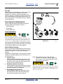
Enhanced Vigilance Required
Related Manuals, Some for Options
407-502M
Nutri-Pro® NP30A Operator
407-313P
Nutri-Pro® NP30A Parts
407-502M
Nutri-Pro® NP40A Operator
407-313P
Nutri-Pro® NP40A Parts
407-613M
Nutri-Pro® NP3000A Operator
407-613P
Nutri-Pro® NP3000A Parts
417-199M
Nutri-Pro® NP4000A Operator
417-199P
Nutri-Pro® NP4000A Parts
12-M-29
CDS-John Blue IP-1300/1800
Impellicone® parts
016-0159-403 Raven AccuFlow™ Operator manual
016-0159-831 Raven SCS-450 Installation, Operation
and Service manual
FVC062
Squibb-Taylor Flo-Max™ manual
016-0159-831 Raven SCS-450 Installation, Operation
and Service manual
Although a common, useful, and still economical
agricultural fertilizer - liquid or gaseous anhydrous
ammonia (NH3) is an extremely hazardous substance
(an EPA EHS hazmat).
EPA EHS (Extremely Hazardous Substance):
Despite the common odor, anhydrous ammonia properties are
dramatically different from those of household ammonia
cleaning solutions (dilute ammonium hydroxide, NH4OH).
An uncontrolled release of NH3 can easily be fatal or cause
permanent disabling injury.
Suffocation, Blinding, Burning, Freezing, Disabling and
Disfigurement Hazards:
Your life and health,
the lives and health of your workers and community,
the continued commercial availability of anhydrous ammonia,
and continuation of agricultural NH3 transport exceptions
depend on you conducting meticulously careful operations.
If you are new to NH3 operations, study everything you can
about this chemical and how to use it safely.
Missing Manual Hazard
The nurse tank(s) you own or are leasing may not have
current manuals. If so, the nurse tank topics in this
manual need your attention. These pages cannot be a
substitute for a complete and current nurse tank cart
manual, but they cover important information for using
nurse tanks safely.
2013-07-15
Table of Contents
Index
407-551M
2
NH3 Safety
Table of Contents
Index
Great Plains Manufacturing, Inc.
Anhydrous Ammonia Education
▲ Read this safety information. It may contain important
information not found in your other reference materials.
▲ Have anyone operating or merely working near the
implement read this safety information.
▲ Do not read only this safety information.
▲ A 20-minute video is no substitute for real anhydrous
ammonia safety training.
Trained, Informed Personnel Only
Anyone working with or near anhydrous ammonia
equipment must be fully trained on NH3 safety, know
exact procedures, know regulations, study all safety
information provided for materials and equipment, and
must be provisioned with adequate personal safety
equipment.
This training may be required by law in your locale.
This manual covers important information,
but is not a substitute for training.
If some terms in this manual are unfamiliar,
do not work with NH3 until they are.
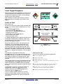
If any topic at right is unfamiliar, assume that the topic
applies to your operations, and your personal safety,
unless you have researched it and ruled it out.
• This manual is not a substitute for the MSDS and other
safety documents provided with the NH3 itself.
• This manual cannot cover all national, regional and
local laws and regulations, nor any organizational or
liability carrier rules.
• This manual cannot cover operations for all nurse
tanks.
• This manual and the Operator manual do not repeat
all of the Raven AccuFlow™ or Squibb-Taylor
Flo-Max™ manuals.
• This manual does not repeat full details of the industry
standards that apply to anhydrous ammonia tanks and
operations.
DOT
PHMSA
OSHA
NIOSH
State Law
State Regs
ANSI K61.1
/CGA G2.1
Insurer
Policies
Entity
Policies
MSDS
ASME
Nameplate
Manual,
Nurse Tank
Manual,
NP30A/NP40A
Manual,
NH3 Meter
Manual,
Coupler
Study All Decals
Anhydrous ammonia implements and tanks display more
decals, more detailed decals, and more
decals
than typical farm equipment.
Have all operators inspect all decals before using the
equipment. Make sure all operators understand what
hazards the decals identify, what the correct operational
procedures are, and what emergency actions to take.
407-551M
Table of Contents
Index
2013-07-15
Great Plains Manufacturing, Inc.
Table of Contents
Index
Read All Manuals
3
Be Aware of Signal Words
Signal words designate a degree or level of hazard
seriousness.
DANGER indicates an imminently hazardous situation
which, if not avoided, will result in death or serious injury.
This signal word is limited to the most extreme situations,
typically for machine components that, for functional
purposes, cannot be guarded.
WARNING indicates a potentially hazardous situation
which, if not avoided, could result in death or serious
injury, and includes hazards that are exposed when
guards are removed. It may also be used to alert against
unsafe practices.
CAUTION indicates a potentially hazardous situation
which, if not avoided, may result in minor or moderate
injury. It may also be used to alert against unsafe
practices.
Definitions
The following additional terms are used throughout this
manual.
NOTICE indicates a crucial point of information related to
the preceding topic. Read and follow the directions to
remain safe, avoid serious damage to equipment and
ensure desired field results.
U
Note: Useful information related to the preceding topic.
R
Right-hand and left-hand as used in this manual are
determined by facing the direction the machine will travel
while in use unless otherwise stated. An orientation rose
in some line art illustrations shows the directions of: Up,
Back, Left, Down, Front, Right.
F
A consistent system of callouts is used for most
implement and nurse tank cart components. See
page 42 for an applicator system illustration.
A11
A51
B
D
L
3-character callouts in the range A11 to A49 refer to
Nutri-Pro® NH3 system components (page 42).
3-character callouts in the range A51 to A87 refer to
nurse tank cart components (pages 10 to 22).
Prepare for Emergencies
▲ Keep emergency numbers for doctor, ambulance, hospital
and fire department near phone. Know the reporting
requirement for spills or releases of the chemicals you are
using. Have contact numbers available.
▲ For anhydrous ammonia operations, have additional
contact information for:
• national response center
• regional (state) response center
• local response center
▲ Have a first aid kit for typical farm injuries, but ignore it for
anhydrous ammonia exposure. The only first aid for
anhydrous ammonia is water.
2013-07-15
Table of Contents
Index
407-551M
4
NH3 Safety
Table of Contents
Index
Great Plains Manufacturing, Inc.
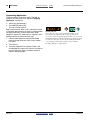
Anhydrous Ammonia Information
NH3 Icons and Decals
Topics in this manual, and the Operator manual, that
concern anhydrous ammonia safety are shown with
these icons nearby.
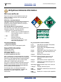
NFPA 704 3-1-0 hazmat diamond:
(see page 5 for details) This information is for emergency
responders, and is typically displayed only at fixed
anhydrous ammonia facilities (terminals), and not on
nurse tanks or implements.
DOT UN 1005 Class 2.2 hazmat placard:
This information is for trained users of the material and
emergency responders. This decal identifies:
• Green Color non-flammable (but see “2”)
• Tank Icon
content is a gas (at ambient temperature
and atmospheric pressure - in the tank, it
may be a liquid)
• 1005
Material Identity:
Anhydrous Ammonia
• 2
Hazmat Class: Division 2.2:
a non-flammable gas that can ignite
under some circumstances
ANHYDROUS AMMONIA
INHALATION HAZARD:
This decal is for all users and the general public.
General NH3 Information
Fertilizer Type: 82-0-0
Chemical formula: NH3
CAS number: 7664-41-7
EC NUMBER (EINECS): 231-635-3
EC INDEX NUMBER: 007-001-00-5
NH3 is a colorless gas at room temperature (any clouds
observed in releases are usually water or ice condensed
from the air by the refrigerant effect of NH3 evaporation).
NH3 is a colorless liquid, and is only a liquid at room
temperature if chilled and/or under pressure.
NH3 gas has a distinctive odor that provides warning of
dangerous concentrations (unless you have impaired
sense of smell, or develop olfactory fatigue/adaptation
due to extended low-level exposure).
Safe field operations can keep exposures below
permissible limits. Unsafe operations, accidents and
malfunctions can result in exposures at ANY
concentration.
407-551M
NH3 Concentrations (Parts Per Million)
5 ppm
Odor detection threshold (most people)
20-50 ppm
Readily detectable odor
25 ppm
NIOSH TWA (Time Weighted Average)
exposure limit
35 ppm
NIOSH STEL (Short Term Exposure Limit)
50 ppm
OSHA PEL (Permissible Exposure Limit,
8 hour TWA)
100 ppm
Rapid eye and nose irritation
150-200 ppm General discomfort, eye tearing. No
permanent health effects on short
exposure
200 ppm
AIHA ERPG-2 one-hour exposure limit
300 ppm
OSHA IDLH (Immediately Dangerous to
Life and Health).
400-700 ppm Severe irritation of eyes, ears, nose and
throat.
1700 ppm
Coughing, bronchial spasms
2000Dangerous: could be fatal in less than 30
3000 ppm
minutes
5000Rapidly fatal - escape may be impossible.
10000 ppm
Table of Contents
Index
2013-07-15
Great Plains Manufacturing, Inc.
Table of Contents
Index
Anhydrous Ammonia Information
5
Why Anhydrous Ammonia (NH3)
Differs…
…from typical liquid fertilizers:
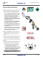
▲ NH3 is intensely hygroscopic:
On contact with water, such as unprotected skin, eyes,
mouth, airway and lungs, it dissolves immediately,
desiccating the cells and forming ammonium hydroxide.
▲ NH3 is highly caustic:
Ammonium hydroxide formed on contact is a strongly
corrosive alkaline solution, resulting in severe chemical
burning of skin and mucous membranes.
▲ NH3 is volatile:
NH3 boils at -28 °F (-33.4 °C), expanding by over 850 times.
It remains liquid in the nurse tank only because it is
pressurized at up to 250 psi. Leaks or above-ground releases
immediately cause an expanding gas cloud. Tanks begin
venting above 116 °F (46.7 °C).
FR
O
E
IT
B
ST
ST
B
IT
E
O
FR
▲ NH3 has a high heat of vaporization:
NH3 is a powerful refrigerant. Evaporating (boiling) liquid
NH3 may be at -100 °F (-73 °C), freezing whatever water it
touches (in addition to the other hazards). This can freeze
clothing to skin, prolonging tissue damage.
0
▲ NH3 is combustible:
Although NH3 generally does not burn with a self-sustaining
flame in the field, it is a significant fire hazard in closed areas
and/or if released near hot ignition sources (such as during
welding on implements).
▲ NH3 is reactive:
Although the reactivity is classified as “0” (in the NFPA
3-1-0 diamond for emergency response purposes), NH3 does
react with various materials, and can produce hazardous byproducts and/or have hazardous side-effects.
CORROSIVE
NH3 is corrosive to a surprising number of metals (see
page 35). Repairs with incompatible parts are likely to result
in malfunctions and a serious accident. Brass parts in
particular can fail rapidly, from the inside out.
Mixing NH3 with some common household and agricultural
chemicals can, for example, produce highly toxic gas. Never
mix NH3 with acids.
▲ NH3 is attractive to criminals:
Do not leave a loaded tank unattended. Secure your tank.
Clandestine lab operators steal NH3 from unattended nurse
tanks. Criminals and vandals often leave a tank in an unsafe
state.
2013-07-15
Table of Contents
Index
407-551M
6
NH3 Safety
Table of Contents
Index
Great Plains Manufacturing, Inc.
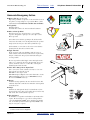
Personal Safety with Ammonia
▲ Carry personal flush water and wear Personal Protective
Equipment (PPE) at all times when working with or near
the nurse tank, and when working with an applicator not
known to be completely purged. Minimum PPE is:
• Carry a sealed squeeze container with 8-10 fluid
ounces (270 ml) of clean water or saline solution.
• Wear non-vented chemical splash goggles
specified for use with anhydrous ammonia. If you
wear glasses, make sure the goggles seal
completely. A vented full face mask provides extra
splash protection, but is not a substitute for primary
non-vented eye protection.
• Wear long cuff chemical gloves specified for use
with anhydrous ammonia. Turn back the cuff ends
to catch any liquids when arms are raised.
• Wear clothing made of heavy, tightly woven fabric,
that can be closed at the neck, and at the cuffs of
long shirt sleeves and long pants. Wear boots or
high, closed shoes.
• Have a mirror for inspecting ends of fittings, ports
and hoses. Never point an NH3 source at your face.
• Great Plains strongly recommends carrying a
wireless telephone or 2-way radio.
▲ Do not wear contact lenses when working with/near
anhydrous ammonia, nor with equipment that may contain
residual NH3 liquid/gas. NH3 can cause permanent eye
damage faster than you can remove contacts for eye
washing.
▲ Unfrozen wash water is required. Completely replace water
daily or more often in the 5 gallon (19 liter) tanks on nurse
tank cart and on implement. Wash water tanks may be
vented to allow the water out at the tap. The vent allows
NH3 gas to enter and gradually form an ammonia solution.
▲ Respirator?
Full face piece respirator protection is required for workers
at fixed ammonia facilities, but not for field operations.
Should you choose to use a full face respirator when
operating the applicator, be aware of two risk factors:
1. Loss of Warning: Filter cartridges may reduce
ammonia odor, preventing detection of
malfunctions or dangerous fume concentrations.
2. Over-Confidence: Typical respirators are intended
for extended low-level exposure, or escape from
high levels. They do not provide extended
protection at or above IDLHa (300 ppm).
?
?
a. A vapor concentration Immediately Dangerous to
Life or Health
407-551M
Table of Contents
Index
2013-07-15
Great Plains Manufacturing, Inc.
Table of Contents
Index
Anhydrous Ammonia Information
7
Ammonia Emergency Action
▲ Have a plan. Execute the plan.
Expect the possibility of exposure or uncontrolled release in
any phase of setup, transport or operations. Have contact
information at hand. Know the wind direction at all times.
▲ Act Quickly:
Training matters.
You must know what to do, and act without hesitation.
▲ Move or Turn Up-Wind:
The first priority is to avoid exposure, or stop further
exposure. On splash or spill, get out of the vapor cloud.
Move up-wind.
If a leak is detected while operating in the field, turn the
tractor into the wind, lower the implement into the ground
and perform an emergency flow shut-off. Pull the rope.
If a breakaway occurred, move the tractor some distance
upwind from the disconnected nurse tank.
▲ Apply First Aid:
Treat exposures with water flushing (and only water or
saline solution, unless instructed otherwise by a physician).
Irrigate continuously. Get professional medical help as
soon as possible.
Do not stop with one flush. Apply water until a physician
takes over or instructs otherwise. In particular, do not use
lotions, ointments, salves or creams. They can trap the
harmful agents under the skin.
▲ Close Valves Only if Not in Vapor Cloud
Once clear of the cloud, evaluate if it is safe to close any
shut-off valves not already closed.
DO NOT re-enter vapor cloud.
DO NOT attempt leak/spill control other than valve closure.
If Raven SCS 450 console is on, set MASTER switch off.
Do not turn POWER switch off.
▲ Escape:
Continue moving upwind of any uncontrolled release. The
wind may shift. On a calm day the ammonia cloud expands
in all directions.
▲ Notify:
Summon any aid required. Notify local authorities of any
uncontrolled release. Protect the public. Protect livestock if
that can be done without further exposure.
▲ Stay in Contact:
Be available to responders with whatever information they
require. Do not attempt to correct the accident problem
yourself. Standard field PPEa safety equipment is suitable
only for normal operations and escape. Field PPEa is not
safe for emergency response.
a. PPE: Personal Protective Equipment
2013-07-15
Table of Contents
Index
407-551M
8
NH3 Safety
Table of Contents
Index
Great Plains Manufacturing, Inc.
Ammonia Nurse Tanks
Use nurse tanks with proper current safety certification,
and current safety equipment and features.
Consult with your anhydrous ammonia supplier for safety
information and correct safe handling, transport and use
of anhydrous ammonia.
Consult with local and regional authorities on Safe and
legal use of anhydrous ammonia, including emergency
and environmental contacts, and release reporting
requirements.
Review any decals and manuals available for your nurse
tank cart, and for any of its components. There may be
separate manuals for the tank, running gear, indicators,
valves and fittings.
This manual covers typical operations for a
representative NH3 nurse tank cart. Compare the
features and controls of your cart to the model cart, so
that there will be no confusion about instruction steps.
Control Variation Hazard:
If you are using multiple nurse tanks, study each one
separately. Unless they are owned by you, and known to be
identical, there is a high probability that there are differences
between them, even if they are all from the same terminal.
Trailing Nurse Tanks Only:
This manual, and the applicator Operator manual, do not
cover operations with “applicator” anhydrous tanks.
A consistent system of callouts is used for most nurse
tank cart components.
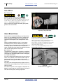
A51
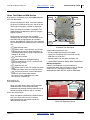
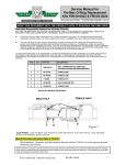
Figure 1
Typical NH3 Terminal
31558
Missing Information Hazard:
Take action to inform yourself. The majority of anhydrous
ammonia nurse tanks do not have an operator manual, for the
complete cart or for just the tank. Any manual that is available
may not accurately document the cart at hand, due to expired
component replacement, and/or complete tank replacement.
Field Operations Only:
This manual, and the applicator Operator manual, cover only
nurse tank field operations. Nurse tank terminal operations,
transport, storage and detailed maintenance are beyond the
scope of this manual.
3-character callouts in the range A51 to A87 refer to
nurse tank cart components, decribed on page 10
through page 22.
Nurse Tank Security
Standard Tank Controls:
This manual, and the applicator Operator manual, assume
standard (unlocked) tank fittings and controls are in use.
407-551M
Table of Contents
Index
2013-07-15
Great Plains Manufacturing, Inc.
Table of Contents
Index
Ammonia Nurse Tanks
9
Nurse Tank Safety
Many nurse tanks in use today were originally assembled
by cart integrators who are no longer in that business, or
assembled by an implement dealer, or by an end user.
Cart running gear often remains in service for decades,
with a periodic tank replacement, at which time it is
essentially a completely different nurse tank cart.
Hoses and various fittings are limited-life components
that are routinely replaced, and the replacements may
not precisely match the original parts.
In as few as four years, any original cart documentation
may no longer accurately describe the cart in its current
configuration.
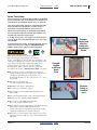
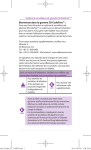
Example:
Peeling and
Missing
Safety and
Informational
Decals
If you do not have a current, up-to-date operator manual
for the nurse tank cart, study the “Ammonia Nurse
Tanks” section of this manual, starting on page 8.
Missing Information Hazard:
Many nurse tanks have no operator manual.
They may not have even a tank operator manual.
If there is a manual, the cart may have been modified, or the
tank replaced. Fittings are routinely replaced. Study how the
nurse tank works. The tank configuration, fitting, hoses,
indicators and controls may vary from the original
documentation (if any), and vary from the typical tank
described in the section “Ammonia Nurse Tanks” on page 8.
▲ Do not fill, accept or use a tank unless it conforms to
current regulatory and safety requirements, and passes a
careful inspection. Print pages 23 and 24 to use as
checklists. If the answer to any of the items is “no”, do not
use the tank.
Example:
Illegible
or Missing
Name
Plate
▲ Pull-type two-axle tanks only
(no semi-mounted nurse tank carts).
▲ Maximum total capacity 3000 gallons.
Example:
Failing or
Outdated
Hose
▲ Never fill to more than 85% capacity.
▲ Never transport a nurse tank behind an implement on
public roads.
▲ Never park a tank on public roads or in populated areas.
▲ Transport slowly: 20 mph (32 kph) maximum
▲ Never leave a loaded NH3 tank unattended.
Never leave a nurse tank unsecured.
▲ Know and follow the law applicable to anhydrous ammonia
tanks, transfer, transport and application. Some
jurisdictions require permits and specific documents and
equipment configuration for highway transport.
▲ Know how to perform a basic safety inspection of a nurse
tank (page 23). Do not fill or accept or fill a tank that fails
inspection.
2013-07-15
Table of Contents
Index
407-551M
10
NH3 Safety
Table of Contents
Index
Great Plains Manufacturing, Inc.
Nurse Tank Cart Components
For use with a Nutri-Pro® applicator, the nurse tank must
be a full-trailering pull-type with two or more axle running
gear. The Nutri-Pro® is not designed to pull a semimounted tank.
Note: Callout numbers A51 through A87 identify the
same nurse tank components throughout this
manual and the applicator Operator manual.
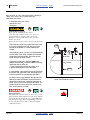
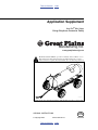
Cart Hitch
Refer to Figure 2
A51 A Nutri-Pro® applicator requires a nurse tank with a
clevis hitch having a locking 1 inch (2.5 cm) pin. See
the applicator Operator manual for cart hitching and
page 31 for unhitching.
A52 At least one safety chain is required. In some
regions, regulations may already require two safety
chains. Each chain, clasp, and weld must be rated
for the gross weight of the loaded cart.
A54
A52
A53 The tongue may have supports or caddies for hose
management (the depicted cart has the Acme
parking plug on top). Make sure you understand the
purpose of any tongue features.
A53
A51
When the nurse tank hose is attached, check that
the forward point at which it is secured to the tongue
or cart frame is at least 3 feet (92 cm) from the
implement break-away, with enough slack to elevate
the hose at least 13 inches (33 cm) above the
implement breakaway.
Figure 2
Nurse Tank Hitch
31559
Note: Nutri-Pro® implements do not provide a lighting
harness at the rear hitch, as field operations do not
require nurse tank lights. If the nurse tank has
lights, make sure there is provision to secure that
harness during field operations.
Note: A Nutri-Pro® implement does not provide passthrough connections for air, hydraulic or electric
brakes, as field operations do not require brakes.
If the nurse tank has brakes (rare), make sure they
can be set to off (freewheeling), and there is
provision to secure the unconnected brake lines
during field operations.
A54 Nurse tank cart tongues typically have unlimited
vertical movement. If the tongue pivots have stops,
make sure the clevis can be elevated to at least
48 inches (122 cm) above ground (for implement lift
in field turns).
407-551M
Table of Contents
Index
2013-07-15
Great Plains Manufacturing, Inc.
Table of Contents
Index
Ammonia Nurse Tanks
11
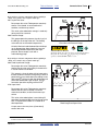
Nurse Tank Front End
A cart may have one or two tanks. A two-tank cart often
has a separate hookup for each tank. A two-tank, twohose cart may be used with a dual-cooler implement, or
a single-meter implement (one tank after another).
A58
Refer to Figure 3
A55 UN1005 decal:
See page 4. This information is for trained users of
the material and emergency responders.
A56
A55
A59
A56 25 MPH mirror image decal:
This decal is for the benefit of the operator
transporting the cart on public roads. It reads legibly
in a rear view mirror.
A57 Acmea parking plug:
An acceptable nurse tank must have a means of
securing the outlet end of each hose. This is usually
an Acme-threaded plug mounted on the tank or
tongue. See the applicator Operator manual for
hose hookup and unhitching.
Figure 3
Nurse Tank Front
31559
Figure 4
Acme Hose Coupler
31567
Vapor Exposure Hazard:
Acme plugs typically do not have gaskets, and do not make a
gas-tight seal. Residual liquid or gas in the hose slowly vents
at the plug. Use valves to close lines.
Refer to Figure 4
A58 Acme Female Hose Coupler:
A58
On a leased tank, the terminal may supply no hose,
in which case you need to provide your own.
A58
This end of the hose connects the tank withdrawal
valve to the leading implement inlet at the
breakaway coupler. For use with a Nutri-Pro®
applicator, the outlet end of the hose must be
equipped with a 13⁄4-4 female Acme fitting.
The outlet end of the hose has a swivel collarb or
shroud containing the female Acme fitting. This
allows connection without needing to twist the hose.
Acme hose couplers are intended for hand
tightening only. Do not use tools to make the cartimplement connection. A liquid-tight seal is made by
the gasket in the male Acme fitting on the
implement break-away coupler.
Suffocation, Blinding and Burning Hazards:
Never disconnect at an Acme coupler without first:
• shutting off the line at all valves, and
• bleeding the line at the connection.
Be up-wind for all operations.
a. Acme refers to the ANSI/ASME B1.5-1997 screw thread, which has a coarse trapezoidal thread profile.
b. Acme collars may be aluminum, but all internal coupler components must be NH3-safe, typically stainless steel.
2013-07-15
Table of Contents
Index
407-551M
12
NH3 Safety
Table of Contents
A59 Outlet Hose:
Index
Great Plains Manufacturing, Inc.
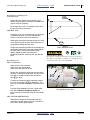
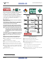
A59. Outlet Hose Configurations
The hose itself and any crimped or swaged NPTa
fittings are limited-life components. Check the
remove-after date on the hose. Valves and other
fittings may also be limited life.
Valves are described on page 13. Hoses may be
supplied in any of several valve configurations. See
table at right. Flow turn-on and turn-off sequencing
is different for each hose configuration. See
“Starting NH3 Tank Flow” in the applicator
Operator manual and “Stopping Application” on
page 29.
A59a. No Valves
A61b
A59b. Valve at Outlet End
A61a
A59c. Valve at Inlet End
A63
A59d. Valve at Both Ends
Figure 5
Nurse Tank Hose Configurations
31567
Figure 6
Hose Data Stripe
31535
Refer to Figure 6
A60 Nurse Tank Hose Body:
Hose data is printed on the full length of the hose.
The key information for operators is that the hose is
designed for “ANHYDROUS AMMONIA” use, and
that the replace-by “REMOVE ... BEFORE” date
has not yet arrived.
Do not rely exclusively on the expiration date.
Inspect the hose for excess wear, damage and
other signs of imminent failure. See hose checklist
on page 23.
a. National Pipe Thread (tapered). Never disconnect anhydrous ammonia NPT fittings in routine use.
407-551M
Table of Contents
Index
2013-07-15
Great Plains Manufacturing, Inc.
Table of Contents
Index
Ammonia Nurse Tanks
Refer to Figure 7
A61 Hose Valve(s)
If the nurse tank hose has one or more valves, study
how they work.
13
A61b
Hose valves are typically hand wheel valves (as
shown A61b ), or lever valves. Read any documents
provided for the valves. Have the terminal or dealer
explain how the valves work.
A62
Suffocation, Blinding and Burning Hazards:
Never test an anhydrous ammonia hose valve unless you
are absolutely certain the hose and valve bodies are
empty, or both hose ends are securely connected to sealed
systems.
Figure 7
Hose Shut-Off and Bleed Valves
31535
▲ A two-valve hose can contain a substantial amount of
NH3 even when completely disconnected. See “Avoid
Line Traps” on page 37.
▲ Older ball valves can contain NH3 inside the ball when
closed, even though disconnected at both ends.
See “Avoid Ball Traps” on page 38.
Follow instructions for bleeding and checking. Never use
a valve handle as a carrying handle. Keep hands clear of
bleed valves when carrying a hose.
Refer to Figure 8
A62 Bleed Valve(s):
Hose valves typically have bleed valves. The
purpose of a bleed valve is to perform a controlled
release, via an orifice A62a , of any fluid or gas
trapped in the closed line prior to disconnect at a
nearby Acme fitting.
A single bleed valve may be located on the inlet or
outlet side of the valve, and only protects that side
of the circuit when the valve is closed. More rarely, a
shut-off valve has bleed valves on both sides of the
valve.
A62a
Study the location of all bleed valves on your nurse
tank and implement.
Figure 8
Bleed Valve
Detail
31569
Suffocation, Blinding and Burning Hazards:
Be up-wind when operating a bleed valve.
Wear chemical gloves when operating a bleed valve.
Wear goggles when operating a bleed valve.
Do not place your body or head in front of the orifice.
Follow a check-list when operating a bleed valve.
Open a bleed valve slowly.
2013-07-15
Table of Contents
Index
407-551M
14
NH3 Safety
Table of Contents
Index
Great Plains Manufacturing, Inc.
Refer to Figure 9 (depicting a hydrostatic relief valve, with a
bleed valve for scale)
A63 Hydrostatic Relief Valve:
Hydrostatic relief valves may be found at multiple
locations, typically anywhere that NH3 could be
trapped (such as in a dual-valve hose).
A63
These are usually identified by a black polymer cap.
If the cap is missing, the valve may have been
activated at some time.
Hydrostatic relief valves are designed to open at
pressures higher than the nurse tank pressure relief
valve A80 (page 18, 250-265 psi). Normal excess
pressure vents at the nurse tank pressure relief
valve. A release at a hydrostatic relief valve
indicates a malfunction or operator error.
Figure 9
Hydrostatic Relief Valve
31564
Hydrostatic relief valves are usually limited-life
components.
Nurse Tank Forward Fittings
Decals on the tank or protective structure may identify
the valves and fittings. Valves may be color-coded. Make
sure all operators know where each valve or fitting is
located. Several of the valves have a similar mechanical
appearance.
}
Refer to Figure 10 and Figure 11
A welded roll cage, normally located at the top front of
the tank, contains all the operating and status fittings
except the relief valve ( A80 , page 21), and the drain valve
( A79 , page 21).
As the tank operator, you will operate one of these
fittings (the withdrawal valve A66 ), and periodically check
two others (the pressure A68 and float A71 gauges).
Figure 10
Nurse Tank Forward Fittings
You need to know the functions of all of the fittings in this
group for purposes of tank inspection and acceptance.
407-551M
Table of Contents
Index
31560
2013-07-15
Great Plains Manufacturing, Inc.
Table of Contents
Refer to Figure 11 (some components shown exploded for
clarity - never remove any except the outlet cap).
A64 Outlet:
The inlet end of the nurse tank hose attaches to this
fitting, which is located at the withdrawal valve A66
(which itself may not be on the tank top. See
page 16).
Index
A64
A65
Ammonia Nurse Tanks
A66
A67
15
A70
This may be a male Acme fitting, and if so should
have a an Acme cap on it when the hose is
disconnected. This Acme fitting may be a different
size than the implement 13⁄4-4 fitting, and if so, will
only accept one end of the hose.
If the hose connects with an NPT fitting, it is not
intended for routine disconnection.
A65 Excess Flow Valve:
This (usually time-dated) fitting may not be present,
or may be internal to the withdrawal valve A66 . Its
function is to substantially obstruct flow if an
unusually high flow is detected, such as a complete
shearing of the hose or a major breach in the hose.
If present, and correctly specified for the hose size
and maximum application rate, field operators do
not normallya interact with this fitting.
Figure 11
Nurse Tank Outlet Fittings
31574
Ammonia Release Hazard:
Do not approach a breached hose. In the event of a hose
breach, an excess flow valve does not completely shut off
NH3 flow. It reduces flow, which may still be a substantial
fraction of a gallon per minute. This flow may or may not
be marked by a visible cloud. This flow rate is beyond the
capabilities of field PPEb. Summon emergency
responders.
Note: An excess flow valve may also be present at
the liquid filler valve A67 or the vapor
valve A70 .
a. It is worthwhile to learn if an excess flow valve is installed, how to know if it has engaged, and what the reset procedure is. Also, an
incorrect configuration of undersize I.D. fittings on the outlet side of an excess flow valve could result in the valve failing to operate in
the event of a breach. If any reducer bushing or fitting present, reconsider accepting the nurse tank.
b. PPE: Personal Protective Equipment
2013-07-15
Table of Contents
Index
407-551M
16
NH3 Safety
Table of Contents
Index
Great Plains Manufacturing, Inc.
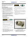
Refer to Figure 12 (some components shown exploded for
clarity - never remove any except the outlet cap).
A66 Withdrawal Valve:
In field operations, this valve is
opened first, and
closed first.
Ammonia Release Hazard:
Never open the withdrawal valve unless:
a. all other valves and bleed valves, are closed, or;
b. the implement is configured and ready for use.
Always be on the up-wind side for valve operation.
Always open slowly.
Always check for signs of release when opening this valve.
The withdrawal valve is the application outlet valve.
It is usually located on the tank top, but may be
located on the bottom. It is color coded red or
orange.
A66
The withdrawal valve may have an integrated bleed
valve or relief valve. Keep all bleed valves closed
except during disconnections. Be aware of relief
valves and stay up-wind of them.
NH3 GAS
A top-mount valve has a “dip tube” A66a which
collects the liquid NH3. Note that there is no pump.
Application flow is driven by:
a. vapor pressure of the NH3 gas above, and
b. gravity siphoning due to tank elevation.
NH3 LIQUID
A66a
In cold weather, vapor pressure may be insufficient
to support high application rates. See page 25 for
further information on cold weather operations.
Figure 12
Nurse Tank Withdrawal Valve
As there must be a gap between the dip tube inlet
opening and the tank bottom, there will be some
amount of ammonia that cannot be withdrawn as
liquid. This is normal and also provides safety. The
residual liquid ensures that the tank contains only
NH3, under positive pressure.
31574
Explosion Hazard:
Stop application when the flow meter and cooler pressure
gauges indicate that the liquid level in the nurse tank has
reached the dip tube inlet. Leave the residual NH3 in the
tank. Attempts to apply all of the liquid NH3 could cause
air to be introduced to the tank, creating a potentially
combustible mixture.
407-551M
Table of Contents
Index
2013-07-15
Great Plains Manufacturing, Inc.
Table of Contents
Index
Ammonia Nurse Tanks
Refer to Figure 13 (some components shown exploded for
clarity - never remove any except the outlet cap).
A67 Liquid Filler Valve:
17
A68
A67
Do not open this valve. Field operators need only
confirm: valve closed, in sound mechanical
condition, and Acme cap secure.
This valve, color coded red or orange, is used only
during tank fill at a terminal.
NH3 GAS
A68 Pressure Gauge:
NH3 LIQUID
This gauge reports the pressure (usually in psi) of
the NH3 gas at the top of the tank. The reading
varies with tank and ammonia temperature.
A freshly filled tank reads between 50 and 250 psi
(at air temperatures above freezing). Learn the
relationship between temperature and vapor
pressure. Do not accept a tank with a
malfunctioning gauge.
Figure 13
Filler Valve and Pressure Gauge
31574
Ammonia Release Hazard:
At 120°F (40°C), the vapor pressure reaches 250 psi. Above
this point, the relief valve ( on page 21) periodically
operates, and small NH3 releases occur.
Refer to Figure 14 (some components shown exploded for
clarity - never remove any except the outlet cap).
A69 Fixed Liquid Level Gauge:
Do not open this valve. Field operators need only
confirm that the valve at this fitting is closed and is
in sound mechanical condition.
This gauge is a short dip tube, with its lower end at
the 85% fill level in the tank. During filling, if terminal
personnel have any doubt about the reading on the
float gauge A71 , they may open the fixed gauge and
see if what is released is gas or liquid. This is a
hazardous operation requiring terminal PPEa.
A70 Vapor Valve:
A69
A70
A71
NH3 GAS
NH3 LIQUID
Do not open this valve. Field operators need only
confirm that this valve is closed, is in sound
mechanical condition, and that the Acme cap is
secure.
This valve, color coded yellow, is used during fill
operations to recapture NH3 gas from the top of the
tank, as liquid fills the bottom. It is closed for all
other operations.
Figure 14
Fixed Gauge and Vapor Valve
31574
A vapor return valve may have a [time-dated]
excess flow valve.
a. PPE: Personal Protective Equipment
2013-07-15
Table of Contents
Index
407-551M
18
NH3 Safety
Table of Contents
Index
Great Plains Manufacturing, Inc.
Refer to Figure 15 (some components shown exploded for
clarity - never remove any except the outlet cap).
A71 Liquid Level Float Gauge:
A71
Check this gauge when accepting a tank. It needs
to be in sound mechanical condition, legible, and
reading no higher than 85.
This gauge has a mechanical float that is coupled to
the indicator needle. Float gauges typically report
0-100 percent of fill.
NH3 GAS
Float gauges are typically mounted at tank top,
facing up, but may also be installed at 45°, with face
tilted up, or horizontal, with face to front or side.
NH3 LIQUID
On a leased tank, learn the reading to expect when
the tank level reaches minimum-usable. It may be
an indication above, at, or even below zero.
Figure 15
Float Gauge
The gauge reading may be inaccurate if the tank is
on a slope, or has just been moved (due to
sloshing).
407-551M
Table of Contents
Index
31574
2013-07-15
Great Plains Manufacturing, Inc.
Table of Contents
Index
Ammonia Nurse Tanks
19
Nurse Tank Sides and Mid-Section
Refer to Figure 17 (depicting a pre-1988 ASME nameplate)
A72 Tank Nameplate:
A72u
A72p
A72r
Locate and inspect this plate. It may be anywhere
on the tank (but will be on the tank, and not on the
running gear or tongue). It is often at top center.
Check that the plate is present, and legible. The
1966 vintage plate depicted at right has marginal
legibility in places.
A72s
A72m
Do not accept a nurse tank with an illegible
nameplate. Do not accept a nurse tank that is not
consistent with the requirements of anhydrous
service. See ANSI K61.1/CGA G-2.1 for a complete
list of requirements, but some key items to check for
are:
•
A72m
•
A72r Repair stamp - normally blank. An “R” here
indicates that the tank has been repaired by an
authorized facility. Do not accept a repaired tank
without an “R” stamp.
•
•
•
A72s
MWAP: Maximum Allowable Working
Pressure (250 PSIG @ 125°F, is minimum and
typical for NH3 service)
A72p
A72t
Figure 16
Anhydrous Tank Nameplate
Manufacturer name
Tank serial number
Type: Must be “AG”
•
A72u Official code “U”-over-”W” symbol. Any other
symbol here means the tank is not NH3 service.
•
A72y Year of manufacture. A tank made before
1999 may lack current safety features.
Do not use a tank made before July 1961.
Do not use an undated tank.
A72y
A72t
31562
A post-1988 nameplate will also:
• be fully welded onto the tank (not riveted)
• specify the standard to which it was built, usually
ANSI K61.1 or CGA G-2.1
• explicitly specify “for anhydrous ammonia use”
• specify MDMT (Minimum Design Metal Temperature)
Missing Nameplate?
If there is no nameplate, check for evidence of
recertification within the last five years, such as FMCSA
Cargo Tank (CT) registration number, or paper
documentation under DOT SP-13554 or CSA B620.
Refer to Figure 17
A73 Safety Decals:
A73
A74
Study any safety decals. Make sure all operators
understand them, and have learned safety
procedures well enough that they know what to do
without consulting the decals after an accident.
A74 Instructional Decals:
Study any operating information provided in decal
form. If the nurse tank cart has no manual,
informational decals may be the only formal
documentation available.
2013-07-15
Table of Contents
Figure 17
Nurse Tank Operations Decals
Index
31563
407-551M
20
NH3 Safety
Table of Contents
Index
Great Plains Manufacturing, Inc.
Refer to Figure 18 (simulated contact information)
A75 Owner Contact Information:
Required by transport regulations, on both sides of the
tank. On a leased tank, verify that the tank owner’s
name, address and phone numbers are present,
legible and up to date.
This information may not be present or required on a
tank that is operator owned.
A76
A75
A76 UN1005 Decal:
A77
Same as A55 on page 11. Required by transport and
hazardous materials regulations, on both sides of the
tank.
A77 INHALATION HAZARD Decal:
Required by transport and hazardous materials
regulations, on both sides of the tank. This decal is for
all users and the general public.
Figure 18
Nurse Tank Center
31560
A78 PPE Kit: (not shown)
A Personal Protective Equipment (PPE) kit must be
supplied with each nurse tank cart. In some locales,
this kit must be in a container affixed to the tank.
The kit must contain at least:
• chemical gloves
• goggles suitable for anhydrous use
If more than one person will be operating the tank in
the field, obtain a second kit. See page 6 for more
information on required and recommended PPEa.
a. PPE: Personal Protective Equipment
407-551M
Table of Contents
Index
2013-07-15
Great Plains Manufacturing, Inc.
Table of Contents
Index
Refer to Figure 19 and Figure 20
A79 Drain Valve:
Ammonia Nurse Tanks
21
A80
Inspect this valve (which may be merely a plug
fitting). Check for general mechanical condition, and
signs of criminal tampering.
Do not open this valve. It is used only to fully drain
the tank for major maintenance.
A80 Relief Valve:
Locate this valve. It is on the tank top, usually under
a protective structure away from the operating
valves. It may be near the wash water tank.
Refilling the wash water tank often places you close
to the relief valve. Be up-wind. Check the pressure
gauge before refilling the wash tank.
At high tank pressures the relief valve is designed to
release NH3 until the pressure drops below 250 psi.
At 120°F (40°C), the vapor pressure reaches
250 psi. Above this point, the relief valve
periodically operates, and small NH3 gas releases
occur.
Refer to Figure 20
A81 First Aid Water:
Check that this tank is present.
Check that it was freshly filled.
Check that hose ends are secure.
A79
Figure 19
Drain and Relief Valves
31574
Ammonia Release Hazard:
On a hot day, remain up-wind of the relief valve at all times.
On a hill, or if the tank is over-filled, or if the tank tips in an
accident, this valve can release liquid NH3.
A80
A81a
Ensure that all operators know how the tank works.
Where is it? How many hoses does it have? Do not
wait until an accident to learn which end of the
hose A81a is which.
Transport and materials safety regulations require
this tank, and the decal A81b that identifies it. The
tank may be installed on the top or side of the nurse
tank.
A81
A82
A81b
Figure 20
First Aid Wash Water Tank
The Nutri-Pro® implement also has a wash water
tank. See “Ammonia Emergency Action” on
page 7 for further information about First Aid Water
tanks.
31560
A82 CAUTION AMMONIA Decal:
Required by transport and hazardous materials
regulations, on both sides of the tank. This decal is
for all users and the general public.
2013-07-15
Table of Contents
Index
407-551M
22
NH3 Safety
Table of Contents
Index
Great Plains Manufacturing, Inc.
Nurse Tank Rear End
Refer to Figure 21
A83 Unit Number:
An emerging regulation requires a visible cart unit
identification string (letters and/or numbers) on
each cart in commercial service.
A83
A84
A84 CAUTION AMMONIA Decal:
Required by transport and hazardous materials
regulations, on both sides of the tank. This decal is
for all users and the general public.
A85
A86
A85 UN1005 Decal
Same as A55 on page 11. Required by transport
and hazardous materials regulations, on both sides,
and end of the tank.
A86 SMV Reflector:
Required for highway transport of any slow-moving
equipment.
Figure 21
Nurse Tank Rear End
A87 Lights: (not shown)
31561
Lights may be required in your jurisdiction. If
transporting at night, or in daytime where daytime
lights are required, test the lights before departure.
Never tow an anhydrous ammonia nurse tank
behind an implement on public roads.
407-551M
Table of Contents
Index
2013-07-15
Great Plains Manufacturing, Inc.
Table of Contents
Index
Ammonia Nurse Tanks
23
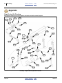
Nurse Tank Acceptance
Use this checklist in addition to any checklists provided
by the tank manufacturer, tank cart manufacturer and/or
anhydrous ammonia supplier.
If no other checklist is available, print these pages to use
a checklist when accepting a tank. If another checklist is
available, this list may include one or more items omitted
from the other lists. Check them all.
Transport the tank separately from the implement.
Consult the towing vehicle and tank operator manuals for
hitching the cart to a separate towing vehicle.
Figure 22
Checklists Matter
Hitch the tank to the implement at the field. This topic is
covered in the applicator Operator manual.
31673
There are two pages for this checklist.
YES ❑
NO ❑
• Does the tank have a visible
numeric, lettered or other unique
identifier?
• Will you have, with you in the field, an YES ❑
operator manual, or manuals, for the
cart, tank and all fittings and controls?
(if not, see CAUTION on page 8).
YES ❑
NO ❑
NO ❑
• Does the cart have a clevis hitch with
1 inch (2.5 cm) pin?
YES ❑
NO ❑
• Have the Nutri-Pro® operators studied YES ❑
the cart manuals?
NO ❑
• Does the cart have two safety
chains?
YES ❑
NO ❑
YES ❑
NO ❑
• Does each tank outlet hose have a
male 13⁄4-4 Acme fitting and cap?
YES ❑
NO ❑
• Are UN “1005” placards on at least
YES ❑
both sides and rear of the tank (set)?
NO ❑
NO ❑
• Are “ANHYDROUS AMMONIA”
labels on at least both sides and the
rear of the tank (set)?
YES ❑
NO ❑
• Are the hoses in good condition; free YES ❑
from cuts, soft spots, bulges,
blistering, kinking, flattening, or
indications that the hose is stretched
or damaged at the coupling?
• Are “INHALATION HAZARD” labels
on both sides of the tank (set)?
YES ❑
NO ❑
YES ❑
NO ❑
• Are all safety and instructional decals
present and legible?
YES ❑
NO ❑
• Is there at least 3 ft (92 cm) of free
cart hose from the front clamp/tie,
and provision to elevate the slack at
least 13 in (33 cm) above the
implement breakaway?
• Does the tank have a fully legible
manufacturer’s name platea stating
standards compliance?
YES ❑
NO ❑
• If the implement is twin-manifold or
twin-pump, does the cart have twin
hoses (if not twin tanks)?
YES ❑
NO ❑
• Is the tank compliant with
YES ❑
ANSI K61.1-1999 or CGA G-2.1-1999
or later (or other NH3 tank standarda
applicable in your jurisdiction)?
NO ❑
• Have means to secure both ends of
the hose during transit to prevent
damage to either hose or
connections been installed?
YES ❑
NO ❑
• Is the tank filled to less than 85% full? YES ❑
NO ❑
YES ❑
NO ❑
• Does the ammonia contain at least
0.2% water?
YES ❑
NO ❑
• Does the cart have rollover
protection structures for all vents,
valves and gauges?
• Do you have dealerb/supplier contact
information?
YES ❑
NO ❑
• Are valves, fittings and gauges rustfree and showing no signs of leaks?
YES ❑
NO ❑
• Do you know the wind direction?
• Do you have the MSDS for the tank
contents?
a. If the tank does not have a plate, or was not built to current standards, you may require a special permit for highway transport, such as
DOT SP-13354 in the U.S. and CSA B620 in Canada (tanks under the former “Green Book” program must transition to B620)
b. Regulations in some locales require tank owner information to be displayed on the sides of the tank in letters at least 2 inches high.
2013-07-15
Table of Contents
Index
407-551M
24
NH3 Safety
Table of Contents
• Is the hose outlet valve tightly
closed?
YES ❑
NO ❑
• Are the tank inlet and outlet valves
tightly closed?
YES ❑
NO ❑
• Are the liquid and vapor valves
labeled or color coded? (red/orange
for liquid and yellow for vapor)
YES ❑
NO ❑
• Does the tank have Acme caps for
vapor and liquid valves?
YES ❑
• Are all limited-life components within
their dated service lives?
Index
Great Plains Manufacturing, Inc.
• Are the tires inflated to specification
(not to exceed the maximum
pressure listed on the sidewalls).
YES ❑
NO ❑
• Is the tongue of the trailer straight
and in good condition?
YES ❑
NO ❑
YES ❑
NO ❑
NO ❑
• Is the tank paint in good condition? Is
it free of peeling, deep scratches,
bubbles and discolored spots (which
might be rust or a leak)?
YES ❑
NO ❑
• Is the tank free of rust and dents, and
showing no signs of cracks or leaks?
YES ❑
NO ❑
• Does the tank have an operating
fixed liquid level float gauge?
YES ❑
NO ❑
YES ❑
NO ❑
• Does the tank have an operating
pressure gauge.
YES ❑
NO ❑
• If the tank has been unattended and
unsecured, is it free of any signs of
tampering?
YES ❑
NO ❑
• Is there a rust-free functional
YES ❑
pressure relief valve, with a rain cap?
NO ❑
• Is the cart frame free of deep rust,
cracks, collision damage and other
signs of possible future failure?
• Is a clearly labelled five gallon
container of fresh clean water
attached to the nurse tank?
YES ❑
NO ❑
• Does the cart appear to be in an upto-date state of lubrication?
YES ❑
NO ❑
YES ❑
NO ❑
• Is one pair of goggles and one pair of
rubber gloves provided on the tank?
YES ❑
NO ❑
• Are the tank and plumbing free of
any signs of leaks?
YES ❑
NO ❑
• Are the tires the correct type and size
for the cart, and are they all of
identical type and size?
YES ❑
NO ❑
• Does the cart have an SMV (Slow
Moving Vehicle) reflector on the
rear?
YES ❑
NO ❑
• Do the cart tires have at least
3⁄ inch (0.5 mm) tread remaining.
16
Do all tires have about equal tread
wear?
YES ❑
• Does the cart have any required
trailer license plate or tags?
• Do you have all required permits/
licenses?
YES ❑
NO ❑
YES ❑
NO ❑
• Are the tires all free of signs of misalignment (uneven tread wear
indicating bent axles, failing
bearings, etc.)?
YES ❑
NO ❑
• Do you have contact information for
local, regional and national
Emergency Response Centers?
YES ❑
NO ❑
• Are the tire sidewalls free of signs of
weathering?
YES ❑
NO ❑
• Do you have a mobile means of
summoning emergency aid, such as
a cell phone? Is there adequate
wireless coverage along your entire
route and in the field?
407-551M
NO ❑
Table of Contents
Index
2013-07-15
Great Plains Manufacturing, Inc.
Table of Contents
Index
25
Anhydrous Application
Get Expert Advice
Anhydrous ammonia is 82% Nitrogen, the highest of any
fertilizer. The compound NH3 is normally a gas at
ambient temperatures. It is retained in the soil only by
chemical reactions and physical mechanisms, primarily
reactions with soil moisture.
Consult with your agronomist about optimal application
timing, rate and depth, based on proposed crop, soil
temperature, soil moisture content and ambient
temperature. Non-optimal applications can result in NH3
loss to the atmosphere, soil drying, and undesired long
term changes in soil pH.
NH3 Temperature and Pressure Relationship
Weather Extremes
Cold Weather Low Flow
Catastrophic Release Hazard:
Do not take measures to boost pressure in cold weather.
Ad hoc boosting could create risk of line rupture or tank
explosion. The Great Plains system is designed for vapor
pressure and gravity delivery only.
Vapor pressure changes with ambient temperature (see
table at right). In colder weather, there may be
insufficient pressure for higher application rates. The
Raven AccuFlow™ Installation and Operation manual
has a temperature-rate-speed chart.
Hot Weather Venting
Unexpected Release Hazard:
Avoid hot weather, or be extra vigilant about remaining
upwind of the tank relief valve ( A80 , page 21). In extremely hot
weather, the tank pressure relief valve will periodically vent
NH3 when the vapor pressure exceeds 250 psi. Tank
temperatures above 116°F (47°C) cause venting.
Degrees F (C)
Pressure (psi)
-28°F (-33°C)
0°F (-18°C)
32°F (0°C)
60°F (16°C)
100°F (38°C)
116°F (47°C)
0 psi
16 psi
48 psi
93 psi
197 psi
250 psi
Anhydrous Ammonia Exposure Hazard:
Keep the nurse tank cool. Stay up-wind of relief valves.
Check the tank pressure gauge. In hot weather, ammonia vapor
releases can occur at a relief valve.
Normally, over-pressure releases occur at the nurse tank relief
valve ( A80 , page 21). It is designed to operate at a lower
pressure than other (hydrostatic) relief valves in the system.
However, with operating valves closed, trapped NH3 could
activate hydrostatic relief valves anywhere in the system.
Direct sun on the tank, or parking the tank in a hot shed,
could result in relief venting well below an actual ambient
temperature of 116°F.
Avoid Dead Calm
The wind is your friend. Normal anhydrous ammonia
operations involve small releases of NH3 vapor.
Accidents, malfunctions and serious operator errors can
result in releases of liquid NH3, which turns into a rapidly
expanding gas cloud. You need to be “up wind” of all
potential releases, and that is only possible if there is at
least a breeze to carry the fumes away from you.
2013-07-15
Lower Operating Limit:
A manifold pressure of at least 10 psi is required for the
AccuFlow™ to operate correctly. If the static pressure prior to
operation is not much above that, it may fall below this limit
when NH3 begins to flow.
Table of Contents
Index
407-551M
26
NH3 Safety
Table of Contents
Index
Great Plains Manufacturing, Inc.
Wash Water
Refer to Figure 23
Empty the 10 gallon implement First Aid Water tank.
Refill it with fresh clean water. If the nurse tank cart is at
hand, refill the nurse tank wash water as well.
The water needs to be changed daily. Water absorbs
ammonia (NH3) vapor from the air, and becomes an
ammonium hydroxide (NH4OH) solution over time.
When emptying wash tanks, use the time and water to
train operators on tank operations, and first aid rinsing
procedures.
Figure 23
First Aid Water Station
Field Operation Safety
31599
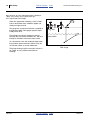
WIND
If field requirements permit, you can minimize exposure
to NH3 vapor with the following recommendations:
Refer to Figure 24
• Check the wind direction.
• Plan passes to be cross-wind and turns up-wind.
• Plan first pass on down-wind side of field.
• Choose your first pass to allow you to be up-wind
while operating valves at the nurse tank and
implement. Opening the emergency shut-off valve
typically requires climbing on the implement from the
right. Starting with the wind from the right is optimal.
Figure 24
Ideal Pass Planning
Anhydrous Ammonia Exposure Hazard:
If field requirements result in any down-wind operations:
-
▲ Use a tractor with a fully enclosed cab. A tractor that is not
fully enclosed exposes the operator to substantially more
NH3 vapor, particularly if field requirements result in
downwind turns or downwind passes.
▲ Have an escape route (up-wind turn) available for all
down-wind operations.
▲ Conduct end-of-pass operations to minimize above-ground
releases.
▲ Be mindful of the risks of olfactory fatigue. You can
“get used to” the odor and fail to notice when
concentrations get dangerously high.
407-551M
Anhydrous Ammonia Exposure Hazard:
Repeated exposure to NH3 vapor may exceed PEL
(Permissible Exposure Limits) and also may induce olfactory
fatigue (adaptation). Over time, you become less sensitive to
ammonia odor, and may fail to recognize dangerously high
concentrations.
Table of Contents
Index
2013-07-15
Great Plains Manufacturing, Inc.
Table of Contents
Index
Anhydrous Application
27
Dry Run
Before activating the NH3 delivery, cautious practice is to
make one dry run pass, including a turn in each
direction. This assures that tine or knife depth is set
correctly, hydraulics are working correctly, the nurse tank
cart is tracking without issue, proper slack exists for all
hoses and harnesses, and the meter console is reporting
correct field speed.
Row Implement Adjustments
Make all applicator adjustments before charging the
metering system with anhydrous ammonia:
• application depth
• coulter depth
• sealer adjustments
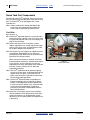
Sealer Adjustment
Ammonia Exposure Hazard:
Fine tune adjustments with dry runs prior to initial
application. Making adjustments after beginning application,
even with tines or knives left in the ground, could cause your
exposure to exceed PEL, leading to health problems or injury.
Figure 25
Adjustments
If you need to make adjustments after application begins,
discharge the system, and then lower the tines or knives
into the ground. Minimize your vapor exposure.
23200,
31593/7
31723
Start of Pass Planning
Ideally, you want NH3 to begin flowing out of the tines or
knives right at the start of a pass, with the tines or knives
already in the ground. This minimizes atmospheric
releases.
Depending on wind direction, tractor capability, available
headlands, and field conditions, there are several ways
to start each pass.
A. Capable Tractor:
Lower implement into ground at start of pass. Pull
forward to set them to operating depth. Start meter
flow. Do not start moving until flow divider pressure
gauge nears typical operating value.
B. Headlands Available, Any Tractor:
Lower implement to ground some distance ahead of
the application area. Move forward slowly. As tines or
knives enter ground, start meter flow.
C. No Headlands, Marginal Tractor:
Lower implement to ground at start of pass. Start
forward movement, then meter flow. Move slowly
until console rate display nears target rate.
2013-07-15
Note: The procedures at left are not operating
instructions or checklists. They are outlines for
planning pass starts. See the step details in the
applicator Operator manual.
Anhydrous Ammonia Exposure Hazard:
When raising in field, be facing into the wind or be turning upwind. Even if NH3 flow was stopped some distance before the
lift point, the tines or knives will still be emitting NH3 vapor
when out of the ground.
Table of Contents
Index
407-551M
28
NH3 Safety
Table of Contents
Index
Great Plains Manufacturing, Inc.
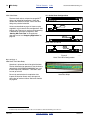
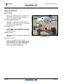
Starting Application
NH3: Possible Chemical Hazard:
Anhydrous ammonia is now flowing into the ground. Some
routinely escapes to the atmosphere. Check for leaks. Take
action if strong odor is detected or a leak seen. Turn up wind.
Turn off flow. Check gauges from tractor cab. Engage
emergency shut-off valve if a leak is detected.
Minor odor during application is normal, particularly if the
tractor cab is ever down wind of recent passes.
Strong or irritating odor indicates a problem. Conditions
may not be suitable for application (soil too dry, cloddy
and deeply cracked, for example), or there may be a
system problem.
Figure 26
Typical Application Screen
31585
Field Turns
a. Before the turn,
set the MASTER switch OFF.
Leave the implement in the ground, and
continue forward movement.
b.
Lift the implement at the turn point.
Major Spill / Equipment Damage Hazards:
Do not turn too tightly. The nurse tank could strike the
implement, be upset, and leak. On 2-Point and Pull-Type
applicators, the nurse tank tongue could strike the caster tires.
On 3-Point applicators, the nurse tank tires could strike
sealers, tine or knife shanks.
c.
Turn up-wind for the next pass.
d. Line up per your start of pass plan.
e. Lower the implement into the ground.
f.
Set the BOOMS 1 switch ON.
g. Pull forward and complete the pass.
407-551M
Ammonia Vapor Release Occurs at Turns:
Avoid down-wind turns.
Do not raise for turns if unprotected individuals or sensitive
livestock are immediately down-wind of the turn. Stop instead.
Turning off NH3 flow prior to raising for turns does deplete
some of the liquid ammonia in the applicator lines, but not all
of it, and considerable vapor remains. At turns, there will be
some release of NH3 vapor, and possibly some NH3 liquid.
Be prepared for it. Minimize exposure to yourself and others.
Turn up-wind immediately if a hazardous concentration of
fumes reaches the tractor cab.
Table of Contents
Index
2013-07-15
Great Plains Manufacturing, Inc.
Table of Contents
Index
Anhydrous Application
29
Stopping Application
Plan your stops. A safe stop requires depleting the
anhydrous, from the nurse tank withdrawal valve to the
tines or knives.
a. What is the wind direction?
b.
Suspend application per “Suspending
Application”, below.
c.
Put on your chemical gloves.
Be wearing your goggles.
d. Carefully approach the nurse tank from up-wind.
Expect some ammonia odor, but if it is extremely
strong, there may be an above-ground release in
progress due to malfunction or part failure. If so,
remain clear until the release subsides.
Ball Valves: Trapped NH3 Hazard:
Avoid routinely closing ball valves (other than the nurse tank
withdrawal valve) with liquid NH3 in the lines. Fluid is
trapped in the line above the valve, may trigger relief valves,
and can get trapped inside the valve ball unless it has a bleed
port (not yet common on nurse tank hoses). See “Avoid Line
Traps” on page 37 and “Avoid Ball Traps” on page 38.
A typical ball valve can trap enough NH3 to make a room the
size of a two-car garage uninhabitable (concentrations above
IDLH in moments). When the ball valve is later opened, while
warm, the NH3 is expelled at high pressure. If the line is
pointed at your face, you could receive a fatal exposure.
e. When safe to do so, shut off the nurse tank
withdrawal valve A66 (page 16).
f.
Re-enter the tractor cab.
i.
Continue field application until both cooler and
divider pressure gauges read zero.
n. Open all bleed valves. Standing up-wind of each,
and making sure orifices point away from you, slowly
open bleed valves at:
• nurse tank hose inlet end A61a (page 13)
• nurse tank hose outlet end A61a (page 13)
• breakaway bleed valve A13 or A16 (page 42)
(whichever is safer)
• cooler temperature gauge A27 (page 42).
j.
Facing into the wind, raise the implement and stop.
o.
k.
Set the MASTER switch to OFF.
l.
Wait at least 1 minute for row line vapor to dissipate.
Close all remaining operating valves:
• nurse tank hose inlet end A61a (page 13)
• nurse tank hose outlet end A61a (page 13)
• emergency shut-off valve A18 (page 42).
p.
Wait at least one hour before moving implement to
any spot near unprotected people or livestock. It will
continue to out-gas ammonia vapor for some time.
g. Turn MASTER switch ON.
h. Resume field application until reported rate begins to
fall. Increase rate to maximum (to fully open Control
Valve).
m. Turn so that the wind is directly from the right.
2013-07-15
Table of Contents
Index
407-551M
30
NH3 Safety
Table of Contents
Index
Great Plains Manufacturing, Inc.
Suspending Application
These instructions are for brief stops in the field, for
example, to make a phone call. See also “Stopping
Application” on page 29.
a. What is the wind direction?
b.
Turn MASTER switch OFF.
This turns On/Off Valve off.
With On/Off Valve off, there is still a substantial amount
of liquid NH3 downstream of all valves, in the flow divider,
row application tubing, and row applicators. When
stopped, in ground, this slowly warms, vaporizes, and is
expelled into the soil. See warning at right.
c.
Continue field application until the Flow Divider
pressure gauge reads zero. Wait at least another
5 minutes.
d. Turn up-wind.
Choking Hazard:
Never raise a recently operated implement when you are
down-wind of the implement. Be or turn up-wind if it is
necessary to raise a working implement. Wear your goggles. A
substantial amount of anhydrous ammonia is rapidly released
if you do not allow time for it to bleed off underground. The
concentration could be high enough to cause irritation,
breathing difficulty or asphyxiation.
e. Leave the implement in the ground. There is still
considerable NH3 vapor in the lines that are open to
the soil. There may also be a modest amount of
liquid in cold tubing loops.
407-551M
Table of Contents
Index
2013-07-15
Great Plains Manufacturing, Inc.
Table of Contents
Index
Anhydrous Application
31
Unhitching Nurse Tank
The procedure is different for exchanging tanks vs.
concluding application.
Exchanging Nurse Tanks
Consult with the nurse tank supplier, and all nurse tank
documents, before unhitching or exchanging tanks.
a. Suspend NH3 application per “Suspending
Application” on page 30.
The purpose of this step is minimize atmospheric
NH3 vapor while working at the rear hitch, because
you may not be able to conduct all unhitching and
re-hitching steps from up-wind of all the tines or
knives.
b.
Position the implement cross-wind, with the wind
from the right, tines or knives in ground.
c.
Use the rope to close the emergency shut-off
valve A18 (page 42).
d. Put on your goggle and rubber gloves.
Control Variation Hazard:
If you are using multiple nurse tanks, study each one
separately. Unless they are owned by you, and known to be
identical, there is a high probability that there are differences
between them, even if they are all from the same terminal.
Final Nurse Tank Unhitch
a. Conclude NH3 application per “Stopping
Application” on page 29.
The purpose of this step is minimize atmospheric NH3
vapor while working at the rear hitch, because you
may not be able to conduct all unhitching steps from
up-wind of all the tines or knives.
f. From the up-wind side, unscrew the nurse tank hose
outlet coupler A58 (page 11).
e. Shut off the nurse tank withdrawal
valve A66 (page 16). Leave the nurse tank hose
valves ( A61 (page 13), if any), open.
g. Secure the outlet coupler with the nurse tank’s Acme
parking plug.
f.
i.
Release the nurse tank safety chains.
j.
Remove the nurse tank hitch pin.
k.
Remove nurse tank from behind implement.
From up-wind, and with the orifice facing away from
you, slowly open the breakaway coupler inlet bleed
valve A13 (page 42).
g. Stand clear and wait for the hoses to discharge.
h. Close all opened bleed valves.
h. From the up-wind side, unscrew the nurse tank hose
outlet coupler A58 (page 11).
i.
Secure the nurse tank outlet coupler.
j.
Close all opened bleed valves.
k.
Release the nurse tank safety chains.
l.
Remove the nurse tank hitch pin.
Folding and Unfolding
Loop Ammonia Exposure Hazard:
Allow no one down-wind of the implement when folding and
unfolding. Applicator tubing loops may contain liquid NH3
that can drain out of tines or knives during wing movement.
This liquid can remain in the loops long after application has
ended.
After parking overnight or longer, any liquid present may be
highly caustic ammonium hydroxide (concentrated NH4OH, a
solution of NH3 and atmospheric moisture) rather than pure
NH3. Assume any liquid in loops is extremely hazardous.
Take full NH3 field precautions.
2013-07-15
Table of Contents
Figure 27
Applicator Loops
Index
31617
407-551M
32
NH3 Safety
Table of Contents
Index
Great Plains Manufacturing, Inc.
General Safety Rules
▲ Keep children, untrained personnel and unprotected
persons well away from equipment that uses anhydrous
ammonia. Children may not recognize or correctly react to
the smell of ammonia.
▲ Have required documents.
▲ Inspect all equipment carefully prior to operations.
Applicator and nurse tank hardware must meet strict
regulatory requirements and be in excellent working order.
Components must be within their expiration dates.
▲ Make sure all wash water tanks are full with fresh, clean
unfrozen water. Change water daily.
▲ Perform all required maintenance. Components with
specific limited service lives must be periodically replaced.
▲ Turn off all hose end and shutoff valves prior to transport.
▲ Check applicator tines or knives. In more challenging
conditions, tines or knives may wear prematurely, causing
stops for cleaning and unplugging, increasing low-level
exposure to anhydrous ammonia.
• Have documents required by law, liability carrier
rules and entity policy.
• Have MSDS (Material Safety Data Sheet) and
supplier documents for the anhydrous ammonia.
• Have any manuals for the nurse tank.
• Have the applicator Operator manual.
• Have the ammonia meter operator manual (such as
the 016-0159-403 Raven AccuFlow™ Operator
manual).
• Have the coupler operator manual (such as the
FVC062 Squibb-Taylor Flo-Max manual).
▲ Have an extra set of safety equipment in the tractor cab.
Have readily available communications to summon
professional aid in case of accident or release.
▲ Park the tank in outdoor shade on hot days and warm sunny
days. Never park near ignition sources. Do not smoke.
▲ On hot days and warm sunny days, do not stand down-wind
of the nurse tank. Even if the air temperature is below
116 °F (46.7 °C), parts of the tank may be above 116 °F,
raising the tank pressure to above 250 psig, and causing the
relief valve to vent NH3 gas until the pressure falls.
▲ Use hitch safety pins. Use safety chains.
▲ Follow operating instructions precisely.
Use checklists.
Do not skip steps.
▲ Do not have unsealed containers of food or drink near the
tank, implement or in the tractor. Any released NH3 will
combine with the water in the food or beverage.
▲ Do not move the implement indoors unless completely
discharged of ammonia, or the indoor area has two
openings (one up-wind), and reliable cross-ventilation.
▲ Always assume that, once used, NH3 residues are present in
implement hoses, tubes and metering system.
▲ Close valve firmly, but do not wrench.
▲ Never allow a hose, tube, pipe end or vent opening to point
at your face or body.
▲ Never use control valves as handles for moving hoses or
climbing equipment.
▲ Route the emergency shutoff cord to the tractor cab prior to
field operations.
▲ Expect small NH3 releases during connection,
disconnection, when raising the implement out of the
ground and after completion of application. Stand up-wind.
▲ Use only CDS-JohnBlue, Great Plains, Raven and
Squibb-Taylor specified parts to repair implement
components originally supplied by Great Plains. Many
common plumbing materials are incompatible with NH3.
Joint compounds must be specified as ammonia-resistant.
▲ Never mix anhydrous ammonia with other chemical liquids.
Reactions with many common materials can be violent
and/or produce highly toxic by-products.
▲ If a fire threatens an anhydrous ammonia tank, evacuate the
area. The tank may heat up faster than the relief valve can
vent the rising pressure, resulting in a catastrophic gas
release and possibly an explosion.
▲ Keep the implement down wind of unprotected persons,
livestock and open water after application.
407-551M
Table of Contents
Index
2013-07-15
Table of Contents
Great Plains Manufacturing, Inc.
Index
Anhydrous Application
33
Breakaway Event
Initially treat a breakaway coupler separation event as
you would any other field emergency. Perform the steps
at “Ammonia Emergency Action” on page 7. Only then
consider performing the steps on this page.
Although the breakaway coupler is designed to separate,
such breakaways are not routine events.
Upon a breakaway, what to do about the breakaway
coupler itself is the last consideration. Priorities are:
1. Protect: Perform basic field emergency action, which
may included summoning emergency responders if
a major release is in progress, or the nurse tank is
tipped over, or is otherwise at risk of a major release.
2. Assess: If the nurse tank appears intact, sound and
stable, determine the cause of the breakaway. It is
unlikely to be something simple that will allow a
timely re-coupling and resumption of application.
If, and only if, the nurse tank is safe to approach, take the
next steps to discharge both sides of the breakaway.
Upon Event: Probable Chemical Hazard:
A 60 cc liquid release to air has already occurred. Assume a
major release is also in progress or imminent. Act accordingly.
Request assistance from trained experts rather than risk
blindness, disfiguring/disabling injury or death.
A breakaway event is most likely due to a major equipment
failure (such as nurse tank running gear fracture), or a gross
operator error (such as towing/turning too fast, or departing
level ground). These cases can result in an immediate serious
spill, or result in a damaged tank at risk of leak at any time.
Even in the case of a basic operator error, such as movement
with only the nurse tank hose connected, both implement
systems and nurse tank hose at breakaway are fully charged
with liquid NH3, right up to the checks in the breakaway
halves. The nurse tank side is under full tank pressurization.
The implement hose may be under pressure.
Discharge Implement:
3. Perform the steps at “Stopping Application” on
page 29. Remain up wind and clear of nurse tank
while doing this.
4. With the orifice pointing away from you, and downwind, slowly open the coupler bleed
valve A16 (page 42) at the implement half of the
breakaway coupler. If you closed the emergency
shutoff after breakaway, each bleed will release
liquid NH3, under pressure, most likely as a spray.
This was an unplanned event. Wind direction may not be
favorable for discharging and re-coupling. If the wind is light
or calm, do not attempt to bleed the breakaway coupler
halves. Your field PPEa is not sufficient for the releases
necessary.
Discharge Nurse Tank Hose:
5. Position the tractor and implement near the nurse
tank. Stop up-wind of the tank, but slightly crosswind of the tank (so that you are not exposed to
residual implement fumes while working around the
tank). Face the tractor into the wind.
6. From up-wind, approach the nurse tank.
7. Close the nurse tank withdrawal valve
A66
(page 16).
8. From up-wind, approach the nurse tank hose outlet
end A58 (page 11).
9. Locate a bleed valve A13 (page 42) on the nurse
tank half of a coupler. Be careful not to touch or
loosen the Acme coupler A58 (page 11). Bleed only
one hose at a time.
10. Position the outlet such that the bleed valve orifice
points both away from you AND points down-wind
AND can be opened and left pointing that way
unattended. If this is not possible, get expert help.
2013-07-15
Table of Contents
a. PPE: Personal Protective Equipment
Index
407-551M
34
NH3 Safety
Table of Contents
11. Opening this bleed valve WILL release the
substantial amount of liquid NH3 presently trapped in
the hose, most likely as a spray. Open the valve very
slowly, just until some fluid appears. Leave the valve
just slightly open.
12. Walk away, up-wind. Stay away until the release
concludes. Carefully open bleed valve completely to
confirm hose is discharged. For dual-cooler, repeat
step 9 through step 12 for the other hose.
Index
Great Plains Manufacturing, Inc.
Before Re-connection: Elevated Exposure Hazard:
Exercise extreme care. Even if the nurse tank is undamaged,
sound and upright, a breakaway event is not a normal re-hitch
situation. A substantial NH3 bleed is required that WILL
release a flow of liquid anhydrous ammonia under pressure.
If the wind is calm or light, do not attempt to bleed the nurse
tank hose. Your field PPEa is not sufficient.
13. Close all breakaway bleed
valves ( A13 and A16 {page 42}), and any nurse tank
hose valves A61 (page 13). Disconnect the nurse
tank half of the breakaway coupler at the Acme
coupler A58 (page 11).
14. Correct the cause of breakaway, only if trivial to do in
the field.
15. Consult the breakaway manual for re-coupling
instructions.
a. PPE: Personal Protective Equipment
407-551M
Table of Contents
Index
2013-07-15
Great Plains Manufacturing, Inc.
Table of Contents
Index
35
Ammonia Maintenance Safety
Over half of NH3 accidents result from equipment failure.
These accidents can be prevented with responsible
stewardship and maintenance.
With most agricultural equipment, using substandard
parts or deferring maintenance until a part fails, merely
costs needless lost time and money.
With NH3 equipment,
using unapproved parts,
deferring maintenance, or
operating components past end-of-life,
could cost lives.
Suffocation, Blinding, Burning, Freezing, Disabling and
Disfigurement Hazards:
Do not perform maintenance with anhydrous ammonia in the
system. Fully discharge the system of NH3 liquid and vapor
before working on the implement. See page 39.
▲ Use only equipment that conforms to applicable
regulations, safety standards and manufacturer
recommendations.
▲ Inspect equipment carefully and thoroughly prior to every
use.
▲ Discharge implement of NH3 residues before performing
maintenance. Assume any liquid in tubing loops is
extremely hazardous. If not pure NH3, it is likely to be
highly concentrated ammonium hydroxide (NH4OH).
▲ Maintain equipment as instructed:
Follow all safety guidelines.
Use only approved replacement components.
Trapped Anhydrous Hazard:
Never service fittings without certain knowledge that the lines
and valves are fully discharged.
Implement systems can trap liquid NH3 between closed valves,
and inside closed valves (even when the lines on both sides of
the valve are discharged). This NH3 would then be released,
under pressure, when a fitting is cracked, or a valve opened,
days, weeks, or months after last field operations.
If an unvented ball valve had been closed on a full line, that
liquid would be released under pressure and vaporize in
seconds. It can contain enough liquid NH3 to render a space
the size of a two-car garage uninhabitable (NH3 concentration
at IDLH within moments).
If either end of the valve is pointed at or near your face, local
concentration would dramatically higher. The outcome could
be blinding, disfiguring, disabling or fatal.
▲ Replace components as they reach their dated life spans.
Incompatible Cleaners
▲ Unless the implement is free of all ammonia residues, avoid
cleaning the implement with products containing halogen
compounds (most commonly chlorine, such as bleach) or
strong oxidizers (such as any “oxi…” products. NH3 can
react violently with oxidizers and halogens, and can
produce toxic gases and/or explosive compounds.
2013-07-15
Incompatible Materials
NH3 is corrosive to:
aluminum (non-anodized)
brass
bronze
cadmium
calcium
cast iron
copper
gold
lithium
magnesium
mercury
silver
zinc
alloys containing these metals, as well as
galvanized surfaces.
Repairs with incompatible parts are likely to soon result in
malfunctions and a serious accident. Brass parts can fail
rapidly, from the inside out. Compounds formed with other
metals may be unstable or even explosive.
Table of Contents
Index
407-551M
36
NH3 Safety
Table of Contents
Index
Great Plains Manufacturing, Inc.
Use a Mirror
Refer to Figure 27
Blinding, Choking and Respiratory Hazard:
Never look directly into an ammonia hose or fitting.
Use a mirror. Always assume that ammonia is present in the
system. There are many ways it can hide, and surprise you
later. See “Avoid Trapped Anhydrous” on page 37.
Use a hand mirror to inspect hose ends, piping ends,
gaskets, vents and orifices.
Figure 27
Inspecting Fitting With Mirror
31565
About Bleed Valves:
Assume there is concentrated NH3 at any bleed valve,
unless you are completely certain which segment of a
line is serviced by that bleed valve, and that the line
segment has been open to the atmosphere for some
time.
When installed on operating valves, it is not always
immediately obvious what the bleed valve protects.
On globe valves, a bleed valve near center-line might be
for venting upstream or downstream. On older ball
valves, a bleed valve near center-line might be for either
side, or even venting the ball cavity itself.
Suffocation, Blinding and Burning Hazards:
Be up-wind when operating a bleed valve.
Wear chemical gloves when operating a bleed valve.
Wear goggles when operating a bleed valve.
Do not place your body or head in front of the orifice.
Follow a check-list when operating a bleed valve.
Open a bleed valve slowly.
Leave it open until all fluid and vapor flow ceases.
This can take a long time.
Refer to Figure 28
The purpose of a bleed valve is to perform a controlled
release, via an orifice 1 , of any fluid or gas trapped in a
closed line prior to operating other valves or uncapping
at a nearby Acme fitting.
1
If the line is discharged, opening the valve may have no
result, or may release a small amount of NH3 vapor at
low pressure. Leave the valve open at the current
position. Move away up-wind. Return when the release
concludes.
If the line is not discharged, opening a bleed valve may
release NH3 vapor at high pressure, or NH3 liquid, most
likely as a spray.
Figure 28
Coupler Bleed Valve
If the there is liquid in the line segment, completion of a
bleed can take a long time. As the fluid turns to vapor, it
chills the remaining fluid, slowing evaporation.
407-551M
Table of Contents
Index
31569
Detail
2013-07-15
Great Plains Manufacturing, Inc.
Table of Contents
Index
Ammonia Maintenance Safety
37
Avoid Trapped Anhydrous
Before servicing anhydrous equipment, or storing it near
untrained individuals, be absolutely certain that there is
no liquid NH3 trapped in the system, and no NH3vapor
present (or only trace amounts).
Follow bleeding and discharge instructions carefully.
Beware of places in the systems where NH3 can be
trapped.
Avoid Line Traps
Refer to Figure 30
Any two line valves in the system, if both closed with NH3
present, can trap that ammonia indefinitely. Line valves
include:
tank withdrawal A66 (page 16),
nurse tank hose valve A61 (page 13),
check valves at a disconnected breakaway,
emergency shut-off valve,
control valve at rate zero A30 (page 42),
On/Off solenoid valve, and
aftermarket section valves.
A61
A61
Valves Closed with
NH3 Present
In a properly designed system, segments not open to the
atmosphere are protected by hydrostatic relief valves,
but the operation of such valves only releases a small
portion of the trapped ammonia.
A62
Normal shut-down instructions, after closing the tank
withdrawal valve, are intended to bleed most of the
system NH3 into the soil. However, there can still be
substantial vapor in the system after that. And if shutdown procedures were not followed (or the state of the
equipment is unknown at time of servicing), you need to
assume that a closed valve represents a risk of trapped
NH3.
The illustration at right depicts a nurse tank
hose A59 (page 12) in use, and shut-off while still full of
liquid NH3. If this hose is removed to an enclosed space,
then opened, it represents an extreme hazard. Vapor
concentrations could rise to well above IDLH levels in
moments.
Valves Open in Use
A63
Figure 29
NH3 Trapped in Line
31616
Clearing a Line Trap
To clear a line segment with possible trapped NH3:
▲ Move the equipment outdoors.
▲ If calm, wait for wind.
▲ Stand up-wind of the bleed valve.
This example system line segment is equipped with relief
orifice-equipped ball valves A61 (page 13), but that only
bleeds the downstream side of a valve ball, the outlet
valve in this example. See page 38 for information about
ball traps.
▲ Point the bleed valve orifice down-wind and away from all
personnel.
The downstream side of this system line segment is
equipped with a bleed valve A62 (page 13). The
upstream side of the inlet valve is equipped with a
hydrostatic relief valve A63 (page 14).
▲ Open the valve very slowly. Once any discharge is
observed, (set any hose down) depart up-wind.
▲ If it’s a hose bleed valve, make sure you can set the hose
down with the valve still pointing in a safe direction.
▲ Remain up-wind until the discharge completes.
If this line segment warms, pressure can rise high
enough to cause periodic releases at the relief valve.
This protects the segment from rupture, but does not
clear the line.
2013-07-15
Table of Contents
Index
407-551M
38
NH3 Safety
Table of Contents
Index
Great Plains Manufacturing, Inc.
Avoid Ball Traps
IDLH Anhydrous Ammonia Exposure Hazard:
Beware of closed ball valves. A ball valve can trap liquid NH3.
If opened when disconnected, this liquid is likely at extreme
pressures, is emitted forcefully and vaporizes rapidly.
A 13⁄4in ball valve can trap enough NH3 to reach IDLH vapor
concentrations, within moments, in a space the size of a two
car garage. Anyone present could be burned, blinded, or
receive serious or permanent lung injury. If this happens in an
enclosed space, the consequences could be fatal.
Legacy Solid
Ball Valve
Newer Orifice
Ball Valve
Valve Open in Use
Refer to Figure 30
Always assume a closed ball valve contains liquid NH3
under high pressure.
The flow gate of a traditional ball valve is a solid steel ball
with a hole through it. When closed, the hole cavity is
sealed by the side walls of the valve body.
Valve Closed with
NH3 Present
If closed with the line full, the ball cavity is full of NH3.
If the valve is well constructed, that fluid remains there
indefinitely, presenting future field and service hazards.
Lines Bled on Both
Sides of Valve
Note: If the valve has a bleed valve and/or relief valve,
those safety valves do not vent the ball cavity when
a solid ball valve is closed. One of them may vent
just the downstream side of an orifice ball with the
ball closed.
Valve Removed for
Service Still Closed
The emergency shut-off valve A18 (page 42) supplied on
Great Plains implements in October 2010 and later has a
relief orifice on the downstream (strainer) side of the
valve.
Figure 30
Legacy Valve Ball Trap
Nurse tank hoses are likely to have solid ball valves
indefinitely. Treat all ball valves as potential traps.
▲ Wear your PPEa when servicing lines and fittings that are
in an uncertain status.
▲ Treat all closed valves as possible traps.
▲ Fully bleed all lines prior to servicing.
▲ Never point a closed valve at your face.
▲ Never carry a valve by the operating wheel or handle.
▲ Open ball valves when both sides of their lines are bled.
▲ Re-check the bleed on at least one side of the opened valve.
▲ If closing a ball valve for storage or parking, first wait for
the valve to warm to ambient temperature to ensure that no
liquid NH3 remains.
▲ Never point a hose at your face.
31614
▲ Never open a closed valve in an enclosed area.
▲ If replacing a ball valve, don’t just check that the new valve
is specified for NH3 service:
Replace orifice ball valves only with orifice ball valves.
Replace solid ball valves with orifice ball valves.
▲ Install an orifice ball valve correctly. The orifice side points
down-stream (in the direction of flow).
a. PPE: Personal Protective Equipment
407-551M
Table of Contents
Index
2013-07-15
Great Plains Manufacturing, Inc.
Table of Contents
Index
Ammonia Maintenance Safety
39
System Discharge
These steps are for clearing an implement for service or
for storage near untrained persons. These instructions
presume that you have followed the steps at:
“Stopping Application” on page 29,
and the nurse tank is unhitched, per:
“Final Nurse Tank Unhitch” on page 31.
For a breakaway event, follow the instructions on
page 33 up through breakaway re-connection. Then
perform a normal shutdown (other than nurse tank
steps), per page 29.
The challenges in system discharge are:
• NH3 liquid can remain in the system after the
recommended stopping procedures.
• NH3 liquid self-cools as it evaporates, slowing
evaporation. It can take a long time for all of it to turn to
vapor, particularly in cooler weather.
• Once there is only vapor in the system, there is usually
little gas movement to drive the rest of it out.
• The applicator tubing loops are usually the last to
clear, and may not fully clear. See sidebar.
Even if no ammonium hydroxide forms, the NH3 vapor in
the system dilutes slowly with air. Harmless trace
amounts, noticed as occasional odor, may remain
indefinitely.
Suffocation, Blinding, Burning, Freezing, Disabling and
Disfigurement Hazards:
Do not perform maintenance with anhydrous ammonia in the
system. Fully discharge the system of NH3 liquid and vapor
before working on the implement.
The applicator tubes are open to the atmosphere at the
tines or knives. When they don’t clear immediately, they
are likely to absorb atmospheric moisture, forming
ammonium hydroxide (NH4OH) in the tubes. This liquid
is highly caustic, and can persist for weeks or months,
but remains liquid at ambient temperatures, is harmless
to the tubing, and emits ammonia vapor slowly. If there
is liquid in the tubes, and it is not cold, it is likely to be an
NH4OH solution, and not pure NH3.
Normal Discharge
At the completion of stopping application and nurse tank
unhitching, all line valves are closed and all bleed valves
are open, and have been that way for at least an hour.
Transport may also have occurred, which aids clearing.
1. Verify that all line valves are closed, and all bleed
valves open. If this is not the case, there is risk of
trapped ammonia. See “Clearing a Line Trap” on
page 37.
2. Carefully walk down-wind of the implement. Check
for ammonia odor. If pungent, there is at least some
pure NH3 vapor in the system, and possibly some
liquid. Give the implement some time to vent.
If there is no, or only mild odor, check the applicator
loops for visible fluid. If only a few hours have
elapsed since application ended, this liquid is pure
NH3. Stay away until it has vaporized.
Figure 31
Applicator Loops
31617
3. From up-wind, check all the fittings and lines. If any
are cold (more than a few degrees below ambient
temperature), liquid evaporation is still in progress or
has only recently completed. Give the implement
more time to vent.
Steps continue on next page...
2013-07-15
Table of Contents
Index
407-551M
40
NH3 Safety
Table of Contents
Index
Great Plains Manufacturing, Inc.
Hydrostatic Relief Valve Maintenance
Relief valves require scheduled replacement and
periodic inspection.
Ammonia Exposure Hazards:
Relief Valve Inspection
▲ Wear safety equipment when inspecting or performing
maintenance on relief valves. Even if the line is bled, NH3
liquid or vapor may still be present.
Inspect relief valves seasonally, and during periodic
maintenance. Check for cap present (step 2) prior to
each application from a fresh tank of anhydrous.
1. Bleed the line at a relief valve before a detailed
inspection. See “System Discharge” on page 39.
Refer to Figure 32 (depicting cooler relief valve)
2. Check that the rain/dust cap is in place and fully
seated.
Do not operate with a missing cap. The cap keeps the
spring mechanism, outlet (vent port) 1 and weep
holes 2 free of contaminants that could prevent valve
operation in an over-pressure situation.
A missing or dislodged cap also indicates that the
valve may have operated, or may be malfunctioning.
Understand and correct the reason for a dislodged cap
prior to field operations.
▲ Always bleed the system before removing a relief valve cap
or performing any more detailed inspection or valve
maintenance.
▲ Never stand in front of or look directly into a relief valve.
Use a mirror. If an overpressure event or valve malfunction
is imminent or in progress, you can expect multiple valve
activations. The initial activation can blow debris as well as
liquid ammonia into your face.
▲ Follow inspection and replacement instructions carefully.
Use the instructions on these two pages only if no separate
instructions were supplied with the original and/or
replacement valve.
Replacement caps are:
breakaway: Continental 400-DC
cooler: Squibb-Taylor 1325-8.
Ammonia Exposure and Loss Hazards:
Understand and correct the reason for any lifted or
missing hydrostatic relief valve caps. If a cap is out of
place, that line section may have been closed with liquid
NH3 present, which later partially vented, dislodging the
cap.
3
1
Liquid NH3 may still be present. Carefully bleed the line
section before taking any other action.
2
It is also possible that the valve disc has deteriorated, or
has debris under the seat and is venting or leaking at
normal operating pressures.
Any hydrostatic relief valve that fully opens (“pops”) must
be removed and re-tested (or simply replaced).
Figure 32
Uncapped Relief Valve
3. Carefully remove the dust cap.
4. Check the replace-by date 3 stamped on the valve.
If it has passed, replace the valve before next use.
5. Clean any clogged weep holes
cleaned, replace the valve.
407-551M
2
. If they cannot be
31635
A23
Note: In severe conditions (such as exposure to salt,
corrosive chemicals or pollutants), or if a valve has
fully opened, you may need to replace a
hydrostatic relief valve sooner than 5 years.
Table of Contents
Index
2013-07-15
Great Plains Manufacturing, Inc.
Table of Contents
Index
Ammonia Maintenance Safety
41
6. Inspect for dirt, sand, grease, paint, damage,
corrosion, signs of tampering or insect activity. If
visible, check the metal surface of the spring.
If debris cannot be easily cleared, replace the valve.
If there are signs of damage, replace the valve.
If there is any question, replace the valve.
7. If a valve is venting at normal operating pressures,
replace the valve.
8. Never force a valve closed. If a valve has remained
open after operating, or is leaking, it is seriously
contaminated or failed. Replace the valve.
9. Never attempt to protect a valve orifice with grease.
Grease can harden over time, and/or collect
contaminants. Either factor could prevent valve
operation in an overpressure situation.
Never plug a relief valve outlet. Relief valves are
economical defense against serious ruptures and
major releases. Help a valve do its job of protecting
you.
Valve Replacement
The safest source for a replacement valve is Great
Plains. Check the latest edition of the Parts manual
(page 1) or the Great Plains internet parts lookup. This
assures a correct and compatible part that reflects any
engineering enhancements.
Ammonia Exposure Hazard:
Fully discharge the system (page 39) before removing an old
valve. Wear protective equipment. If the implement was
recently used, or ammonia was trapped, there could still be
NH3 liquid or vapor behind the valve.
Ammonia Exposure and Rupture Hazards:
Always replace a relief valve with a valve:
Do not attempt to repair or adjust a relief valve.
Hydrostatic relief valves are factory-set and tested, on
specialized equipment, to discharge at a specific
pressure.
▲ that has the same NPT pipe thread size, and;
▲ that is an external “hydrostatic relief valve”,
▲ that is specified for anhydrous ammonia service,
▲ that is rated for the same discharge pressure as the valve
removed (or as otherwise specified by Great Plains or the
manufacturer of the protected component).
On the component being protected by the valve, inspect
the threaded hole after removing the valve. If there are
signs of corrosion, replace the entire component.
Discharge pressure is specific to the valve location in the
system.
Use pipe sealant when installing a replacement valve.
Use only pipe sealant specified for use with anhydrous
ammonia, such as RectorSeal No. 5. Do not use tape.
Using a valve rated too high could result in bursting of
system components and a major liquid NH3 release.
Record the replace-by date of the new valve in the
“Replacement Log” section of the applicator Operator
manual.
Using a valve rated too low could result in unexpected
liquid NH3 release, and material loss during application.
2013-07-15
Table of Contents
Index
407-551M
42
NH3 Safety
Table of Contents
Index
Great Plains Manufacturing, Inc.
Appendix
Single-Cooler NH3 Plumbing
See applicator Operator manual for legends, dual-cooler and section control diagrams.
A16 A15
A13
A12
A11
A23
A17
A14
A47
A48
A19
A48
A47
A21
A22
A18
A34
A24
A20
A27
A28
A40
A33
A45
A42
A44
A25
A49
A43
A41
A29
A32
A45
A31
A26
A30
Figure 33
Plumbing - Single Cooler Single Section System
407-551M
Table of Contents
Index
A46
34960
2013-07-15
Table of Contents
Great Plains Manufacturing, Inc.
Index
43
Index
A
accident .............................................. 7
AccuFlow™ ...................................... 25
acids ................................................... 5
Acme .... 10, 11, 13, 15, 17, 36
AG .................................................... 19
AIHA ................................................... 4
air, in tank ......................................... 16
alkaline ............................................... 5
aluminum ................................ 11, 35
ammonium hydroxide .1, 5, 35, 39
anhydrous ammonia .......................... 1
ANSI ................................................. 19
ANSI K61.1 ...................................... 19
ANSI K61.1-1999 ............................. 23
applicator tank .................................... 8
ASME ............................................... 19
B
ball trap ................................... 29, 38
ball valve .......................................... 35
black cap .......................................... 14
bleach .............................................. 35
bleed valve .............................. 16, 36
hose ........................................... 13
brakes .............................................. 10
brass ......................................... 5, 35
breakaway ............................... 33, 39
bronze .............................................. 35
bushing, reducer .............................. 15
B620 ................................................. 19
C
cadmium .......................................... 35
calcium ............................................. 35
callout .......................................... 3, 8
Canada ............................................ 23
cap, black ......................................... 14
cap, missing ..................................... 40
cap, valve ......................................... 40
Cargo Tank (CT) .............................. 19
carry (hose) ...................................... 13
cart, nurse tank .................................. 8
CAS number ...................................... 4
cast iron ........................................... 35
CAUTION, defined ............................. 3
CDS-John Blue .................................. 1
CDS-JohnBlue ................................. 32
CGA ................................................. 19
CGA G-2.1 ....................................... 19
CGA G-2.1-1999 .............................. 23
chain, safety ..................................... 10
checklists
NH3 tank acceptance ................. 23
chemical burning ................................ 5
children ............................................ 32
chlorine ............................................ 35
Class 2.2 ............................................ 4
clevis hitch ....................................... 10
clothing ........................................ 5, 6
2013-07-15
color code ................................16, 17
color-code ........................................ 14
combustible ................................5, 16
commercial availability ....................... 1
contact lens ....................................... 6
Continental ...................................... 40
copper .............................................. 35
corrosive ............................................ 5
cream ................................................. 7
criminal .............................................. 5
CSA ................................................. 19
CSA B620 ........................................ 23
CT .................................................... 19
D
DANGER, defined .............................. 3
date ............... 12, 15, 17, 19, 40
decal .................................................. 2
decals ................................................ 9
tank ............................................ 19
decal, mirror image .......................... 11
deferring maintenance ..................... 35
definitions .......................................... 3
detection threshold ............................ 4
diamond .......................................4, 5
dip tube ....................................16, 17
directions ........................................... 3
discharge ......................................... 39
documents ....................................... 32
DOT .................................. 4, 19, 23
down-wind ....................................... 26
drain valve ....................................... 21
dry run ............................................. 27
dual tanks ........................................ 11
dual-cooler ....................................... 11
E
EC INDEX .......................................... 4
EC NUMBER ..................................... 4
education ........................................... 2
EHS ................................................... 1
EINECS ............................................. 4
emergency ......................................... 7
emergency response ......................... 5
enclosed cab ................................... 26
end-of-life ......................................... 35
EPA .................................................... 1
ERPG-2 ............................................. 4
excess flow valve ............................. 15
exchange nurse tank ....................... 31
expiration ......................................... 32
exposure ............................................ 7
F
first aid .........................................3, 7
first aid water ...........................21, 26
fixed level gauge .............................. 17
flammable .......................................... 4
flow, stopping ................................... 29
flow, suspending .............................. 30
FMCSA ............................................ 19
Table of Contents
full-trailering ......................................10
FVC062, manual ..............................32
G
galvanized ........................................35
gas cloud ............................................5
gasket ...............................................11
gauge
level, fixed ..................................17
level, float ...................................18
pressure, tank .............................17
gloves .................................................6
goggles ...............................................6
gold ..................................................35
grease in valve .................................41
green ..................................................4
G-2.1 ................................................19
H
halogen ............................................35
hand wheel .......................................13
hazardous material .............................1
hazmat ...............................................1
headlands .........................................27
hose inspection ................................12
hose, carrying ...................................13
hydrostatic relief valve .... 14, 25, 40
hygroscopic ........................................5
I
IDLH .......................... 4, 6, 29, 35
insect ................................................41
IP-1300 ...............................................1
IP-1800 ...............................................1
J
joint compound .................................32
K
knives ...............................................32
K61.1 ................................................19
L
left-hand, defined ...............................3
lever valve ........................................13
lighting ..............................................10
line trap ................................... 29, 37
liquid filler valve ................................17
liquid level float gauge ......................18
lithium ...............................................35
livestock ..............................................7
lotion ...................................................7
M
magnesium .......................................35
maintenance .....................................35
MDMT ..............................................19
mercury ............................................35
mirror ......................................... 6, 36
mirror image decal ...........................11
missing cap ......................................40
MSDS ........................................ 2, 32
mucous membrane .............................5
407-551M
44
NH3 Safety
Table of Contents
Index
MWAP .............................................. 19
S
N
safety chain ......................................10
safety training .....................................2
salve ...................................................7
SCS 450 .............................................1
SCS-450 .............................................1
semi-mounted ............................9, 10
serial number, tank ...........................19
silver .................................................35
single cooler .....................................42
skin ..............................................5, 7
slack, hose ........................................10
SMV ..................................................22
soil drying .........................................25
SP-13354 .........................................23
SP-13554 .........................................19
Squibb- Taylor ...................................40
Squibb-Taylor ....................................32
stainless steel ...................................11
STEL ..................................................4
stopping application ..........................29
substandard parts .............................35
suspending application .....................30
nameplate ................................. 9, 19
NFPA .................................................. 5
NFPA 704 ........................................... 4
NH3 .................................................... 4
NH4OH .............................1, 26, 39
NIOSH ............................................... 4
nitrogen ............................................ 25
Note, defined ..................................... 3
NOTICE, defined ................................ 3
NPT ......................................... 12, 15
nurse tank ................................... 8, 9
nurse tank exchange ........................ 31
nurse tank unhitch ........................... 31
O
odor .................................................... 4
ointment ............................................. 7
olfactory fatigue ................................ 26
orange .............................................. 16
orientation rose .................................. 3
orifice ............................................... 13
orifice, bleed valve ........................... 36
orifice, relief ............................ 37, 38
OSHA ................................................. 4
oxidizers ........................................... 35
P
parking ............................................... 9
parking plug ..................................... 11
pass planning ................................... 27
PEL ........................................... 4, 27
Personal Protective Equipment .......... 6
pH .................................................... 25
placard ............................................... 4
plug, parking .................................... 11
plumbing, single ............................... 42
PPE .................................................... 6
ppm .................................................... 4
pressure gauge ................................ 17
pressure limit, low ............................ 25
pump ................................................ 16
R
Raven ............................................... 32
reactive .............................................. 5
red .................................................... 16
reducer bushing ............................... 15
refrigerant .......................................... 5
relief orifice ............................. 37, 38
relief valve ............................... 17, 21
repair stamp ..................................... 19
replacement cap .............................. 40
respirator ............................................ 6
response center ................................. 3
right-hand, defined ............................. 3
rose, orientation ................................. 3
running gear .............................. 9, 10
407-551M
T
tank temperature ..............................25
tank upset .........................................28
tank, nurse ..........................................8
temperature ......................................17
temperature, tank .............................25
threshold, odor ...................................4
tines ..................................................32
tissue damage ....................................5
toxic gas .............................................5
training ................................................2
trapped .............................................35
tubing loop ........................................35
turns, tight .........................................28
TWA ....................................................4
two-axle ..............................................9
U
UN 1005 .............................................4
unapproved parts .............................35
unhitch nurse tank ............................31
untrained personnel ..........................32
UN1005 ............................................11
V
valve
drain ............................................21
excess flow .................................15
filler .............................................17
hose ............................................13
hydrostatic relief ..........................14
relief (tank) ..................................21
vapor ...........................................17
withdrawal ...................................16
valves
bleed ...........................................36
Table of Contents
Index
Great Plains Manufacturing, Inc.
vapor cloud ......................................... 7
vapor valve ....................................... 17
vent .................................................. 32
venting ................................................ 5
volatile ................................................ 5
W
WARNING, defined ............................ 3
wash water ................................ 6, 21
water tank ......................................... 26
water, wash ........................................ 6
welding ............................................... 5
wind .................................................. 25
wind direction ..................................... 7
withdrawal valve ............................... 16
Y
yellow ............................................... 17
Z
zinc ................................................... 35
Numerics
007-001-00-5, EC index ..................... 4
016-0159-403, manual ..................... 32
016-0159-831, manual ....................... 1
10 psi ................................................ 25
1005, UN code ................................... 4
12-M-29, manual ................................ 1
120 F ................................................. 17
1325-8, cap ...................................... 40
1961 ................................................. 19
1966 ................................................. 19
1988 ................................................. 19
1999 ................................................. 19
231-635-3, EC no. .............................. 4
300 ppm ............................................. 6
3-1-0 ................................................... 4
3-1-0 diamond .................................... 5
40 C ................................................... 17
400-DC, cap ..................................... 40
407-313P, manual .............................. 1
407-502M, manual ............................. 1
407-613M, manual ............................. 1
407-613P, manual .............................. 1
407-776M, manual ............................. 1
417-199M, manual ............................. 1
417-199P, manual .............................. 1
60 cc ................................................. 33
7664-41-7, CAS ................................. 4
82-0-0 ................................................. 4
85% .................................................. 17
2013-07-15
Table of Contents
Index
Table of Contents
Index
Table of Contents
Index
Great Plains Manufacturing, Inc.
Corporate Office: P.O. Box 5060
Salina, Kansas 67402-5060 USA