1
< for USA / Canada >
CONTENTS
I.
Advantage of New MA Remote Controller ...........................................................................2
1. Weekly Timer ......................................................................................................................2
2. Easy Maintenance Function (Only for Mr. SLIM).................................................................2
3. New Display ........................................................................................................................3
I. Advantage of New MA
Remote Controller
II. New Functions
3.1 Dot Liquid Crystal Display (LCD) ........................................................................................................................ 3
3.2 Multi-language Display ....................................................................................................................................... 3
4. The Other Functions ...........................................................................................................3
4.1 Temperature Range Limit Setting ....................................................................................................................... 3
4.2 Auto Off Timer ..................................................................................................................................................... 3
4.3 Simple Operation Lock ....................................................................................................................................... 3
II.
New Functions .......................................................................................................................4
III.
Appearance ............................................................................................................................5
1. Display Section ...................................................................................................................5
2. Operation Section ...............................................................................................................5
IV. Easy Maintenance Function (For Mr. SLIM P series)..........................................................6
1. Maintenance Mode Operating Method ................................................................................6
2. Guide for Operation Condition ............................................................................................8
Check Points ............................................................................................................................................................... 8
V.
How to Select Functions of remote controller ....................................................................9
1. Function Items ....................................................................................................................9
2. Flowchart of Function Setting ...........................................................................................10
3. Screen Structure for Function Setting ...............................................................................11
4. Function Setting Mode ......................................................................................................12
4.1 Change Language ............................................................................................................................................ 12
4.2 Function Setting ................................................................................................................................................ 14
4.2.1 Operation Lock (Operation Function Limit Setting) ............................................................................... 14
4.2.2 Auto Mode Setting................................................................................................................................. 16
4.2.3 Temperature Range Limit Setting.......................................................................................................... 18
4.3 Basic Functions Setting .................................................................................................................................... 20
4.3.1 Remote Controller Main/Sub Setting..................................................................................................... 20
4.3.2 Timer function setting (Weekly timer/Auto off timer/Simple timer) ........................................................ 21
4.3.3 Contact Number Setting for Error Situation ........................................................................................... 33
4.4 Display Change Setting .................................................................................................................................... 35
4.4.1 Temperature Display °F/°C Setting ....................................................................................................... 35
4.4.2 Inlet air Temperature Display Setting .................................................................................................... 36
4.4.3 Automatic Cooling/Heating Display Setting ........................................................................................... 37
III. Appearance
IV. Easy Maintenance Function (For Mr. SLIM P series)
V. How to Select Functions
of remote controller
VI. Unit Function Setting by the Remote
Controller (for Mr. SLIM P series)
VII.Test Run by the Remote Controller (for Mr. SLIM P series)
VIII. Self-Diagnosis by the
Remote Controller (for Mr.
SLIM P series)
VI. Unit Function Setting by the Remote Controller (for Mr. SLIM P series) ........................38
VII. Test Run by the Remote Controller (for Mr. SLIM P series) .............................................42
1. Check Points Under Test Run ...........................................................................................42
2. Test Run using the Wired Remote Controller ....................................................................42
VIII. Self-Diagnosis by the Remote Controller (for Mr. SLIM P series) ...................................44
1. How to Proceed “Self-diagnosis”........................................................................................44
1.1 When a Problem Occurs During Operation ...................................................................................................... 44
1.2 Self-Diagnosis During Maintenance or Service ................................................................................................ 44
1.3 Remote Controller Diagnosis ............................................................................................................................ 45
IX. Monitoring the Operation
Data by the remote Controller (for Mr. SLIM P series)
X. System Control (for Mr.
SLIM P series)
2. Error Code List ..................................................................................................................46
IX. Monitoring the Operation Data by the remote Controller (for Mr. SLIM P series) ..........48
1. How to “Monitor the Operation Data” ................................................................................48
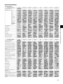
2. Request Code List ............................................................................................................49
XI. External Dimensions
2.1 Detail Contents in Request Code ..................................................................................................................... 53
X.
System Control (for Mr. SLIM P series)..............................................................................58
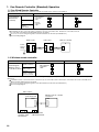
1. One-Remote Controller (Standard) Operation ..................................................................60
1.1 One Wired Remote Controller........................................................................................................................... 60
1.2 Wireless Remote Controller .............................................................................................................................. 60
2. Two-Remote Controller Operation.....................................................................................61
2.1 Two Wired Remote Controllers ......................................................................................................................... 61
2.2 Two Wireless Remote Controllers ..................................................................................................................... 61
2.3 One Wired and One Wireless Remote Controller ............................................................................................. 61
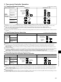
3. Group Control Operation (Collective Operation and Control of Multiple Refrigerant
Systems (2 to 16)) .............................................................................................................62
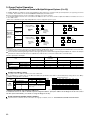
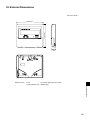
XI. External Dimensions ...........................................................................................................63
1
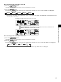
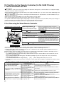
I. Advantage of New MA Remote Controller
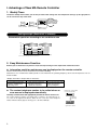
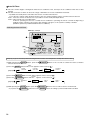
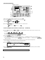
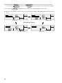
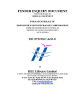
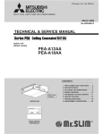
1. Weekly Timer
The built-in weekly timer enables you not only to make on/off settings but also temperature settings. Up to eight patterns
can be set for each day of the week.
TIME SUN
˚F
˚F
WEEKLY
TEMP.
Conventional
Schedule
remote controller remote controller
ON/OFF
Saves you money
and space because
you need only one
remote controller.
Deluxe
remote controller
Setting example (Restaurant in summer)
Quiet Set the
hours temperature high.
78
76
74
72
0
1
10
Lunch time
3
Dinner time
6
7
22
24
End of daily business
Busy Set the
hours temperature low.
80
Start of daily business
Preset temperature (˚F)
Economical operation according to air conditioner use
5
Seven patterns can be set.
12
14
16
18
20
(H)
*Joint research with Japan Facility Solutions, Inc.
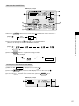
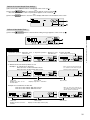
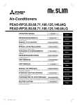
2. Easy Maintenance Function
Enables you to check necessary data on site, drastically reducing the time required for maintenance work.
◆ Information useful for maintenance can be displayed on the remote controller.
Outdoor unit information can be checked even from inside a building.
Furthermore, use of maintenance stable-operation control that fixes the operating frequency, allows smooth inspection, even for
inverter models.
<Display information> Outputs data for nine items.
Compressor information
• Accumulated operating time
• Number of ON/OFF times
• Operating current
Outdoor unit information
• Heat exchanger temperature
• Discharge temperature
• Outside air temperature
Indoor unit information
• Heat exchanger temperature
• Intake air temperature
• Filter operating time
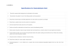
◆ The contact telephone number to be called when an
error occurs is displayed automatically.
Displays the contact number
in case of abnormality.
This helps smooth contact with appropriate personnel in when an error occurs.
The contact telephone number of the maintenance company to be called when an error occurs can be registered in advance. When an error occurs, the contact telephone
number will automatically appear, allowing you to call without difficulty.
Displayed
alternately
Telephone number
registered in advance
2
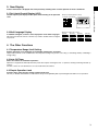
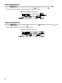
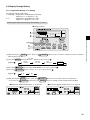
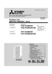
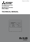
3. New Display
I. Advantage of New MA Remote Controller
Various information is displayed and conveyed clearly, enabling more accurate operation of the air conditioner.
3.1 Dot Liquid Crystal Display (LCD)
The dot liquid crystal display enables quick understanding of the operation
state.
● Display example [Operation mode]
Dot liquid crystal display
TIME SUN
˚F
˚F
TEMP.
3.2 Multi-language Display
In addition to English, contents can be displayed in seven other languages.
This function makes the remote controller very useful in facilities where foreigners
are present.
● Display example [Cool mode]
[English]
[German]
[Spanish]
[Itarian]
[Chinese]
[French]
WEEKLY
ON/OFF
[Russian]
[Japanese]
4. The Other Functions
4.1 Temperature Range Limit Setting
Enables operation of air conditioner at comfortable temperatures at all times.
Upper and lower limits can be established for the temperature setting. This prevents overcooling or overheating, thereby contributing to
energy saving.
4.2 Auto Off Timer
Shuts off wasteful air conditioner operations.
Operation is stopped automatically when the preset time elapses following the start of operation, thereby preventing wasteful operations.
The time can be set from 30 minutes to 4 hours in 30-minute increments.
4.3 Simple Operation Lock
Prevents others from changing settings without permission.
This lets you disable all the buttons or all the buttons except for the [ON/OFF] button, preventing mischief and incorrect operations.
3
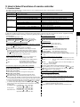
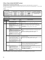
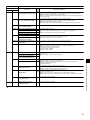
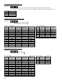
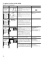
II. New Functions
II. New Functions
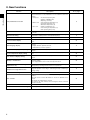
Function
Description
Go to page
Easy maintenance function
Displays information necessary for maintenance.
Below information for easy maintenance of air-conditioner can be displayed.
• Compressor • Accumulated operating time
• Number of ON/OFF times
• Operating current (A)
• Outdoor unit • Heat exchanger temperature (°F)
• Discharge temperature (°F)
• Outside air temperature (°F)
• Indoor unit
• Intake air temperature (°F)
• Heat exchanger temperature (°F)
• Filter operating time (hours)
6
Operation data monitor function
Information necessary for maintenance can be displayed on the remote
controller.
48
Operation Hz fixing
The operation state of inverter models can be monitored using the
maintenance stable-operation control (fixed frequency).
6
Error code monitor function
Error code is displayed in the service inspection monitor.
44
Contact number display
Displays the contact telephone number to be called when an error occurs.
33
Multi language display
In addition to English, contents can be displayed in seven other languages.
• English, German, Spanish, Russian,
Italian, Chinese, French, Japanese
12
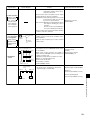
Temperature display (°C/°F) setting
Enables you to set the unit (°C/°F) in which temperatures are to be displayed.
35
Room temperature display setting
Enables you to set whether to show or hide the indoor (room) temperature.
36
Auto heat/cool display setting
Enables you to set whether to display or hide “COOL”/“HEAT” in auto
mode.
37
Weekly schedule timer
Provides a built-in weekly timer that allows you to make on/off and temperature settings.
Up to eight patterns can be set for each day of the week.
23
"Operation limit function setting
(Operation lock)"
Lets you disable all the buttons or all the buttons except for the [ON/
OFF] button, preventing mischief and incorrect operations.
14
Temperature range limit function
Enables you to establish upper and lower limits for the temperature setting. This prevents overcooling or overheating, thereby contributing to
energy saving.
18
Clock function setting
Enables you to set whether to use the clock function.
21
Auto off timer
Stops operation when the preset time elapses following the start of operation.
The time can be set from 30 minutes to 4 hours in 30-minute increments.
By default, the weekly timer is selected.
To switch to the auto off timer, select it using the remote controller’s
function selection.
26
Simple timer
Enables you to set on/off settings in 1-hour increments within 72 hours.
29
Remote controller main/sub setting
Enables you to set the remote controller as the main or sub.
20
4
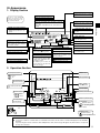
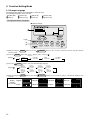
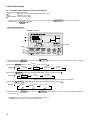
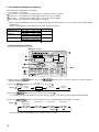
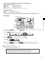
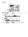
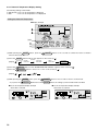
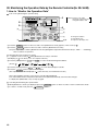
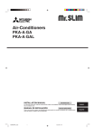
III. Appearance
1. Display Section
“Sensor” indication
Displayed when the remote controller
sensor is used.
Day-of-Week
Shows the current day of the week.
Time/Timer Display
“Locked” indicator
Shows the current time, unless the simple or Auto Off
timer is set.
If the simple or Auto Off timer is set, shows the time remaining.
Indicates that remote controller buttons have been locked.
Identifies the current operation
“Clean The Filter” indicator
Shows the operating mode, etc.
* Multilanguage display is supported.
Comes on when it is time to clean
the filter.
TIME SUN MON TUE WED THU FRI SAT
TIMER
Hr
ON
AFTER
FUNCTION
FILTER
˚F˚C
˚F˚C
“Centrally Controlled” indicator
Indicates that operation of the remote controller has been prohibited
by a master controller.
Timer indicators
AFTER OFF
ERROR CODE
The indicator comes on if the corresponding timer is set.
WEEKLY
SIMPLE
AUTO OFF
ONLY1Hr.
Fan Speed indicator
Shows the selected fan speed.
Up/Down Air Direction indicator
“Timer is Off” indicator
Indicates that the timer is off.
Temperature setting
Shows the target temperature.
Room Temperature display
Shows the room temperature.
Louver display
“One Hour Only” indicator
Indicates the action of the swing
louver. Does not appear if the
louver is stationary.
Displayed if the airflow is set to
low and downward during COOL
or DRY mode. (Operation varies
according to model.)
The indicator goes off after one
hour, at which time the airflow direction also changes.
Ventilation indicator
Appears when the unit is running
in Ventilation mode.
The indicator
shows the direction of the outcoming airflow.
(Power On indicator)
Indicates that the power is on.
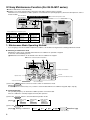
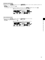
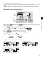
2. Operation Section
ON/OFF button
Set Temperature buttons
Down
Fan Speed button
Up
Timer Menu button
(Monitor/Set button)
Filter
button
(<Enter> button)
Mode button (Return button)
TEMP.
ON/OFF
Set Time buttons
Check button (Clear button)
MENU
Back
Ahead
BACK
PAR-21MAA
Timer On/Off button
(Set Day button)
Opening the
door.
Test Run button
MONITOR/SET
ON/OFF
FILTER
DAY
CLOCK
CHECK TEST
OPERATION
CLEAR
Airflow Up/Down button
Louver button
Operation button)
(
To preceding operation
number.
Ventilation button
(
Operation button)
To next operation number.
Note:
● If you press a button for a feature that is not installed at the indoor unit, the remote controller will display the “Not Available”
message.
If you are using the remote controller to drive multiple indoor units, this message will appear only if the feature is not present
at every unit connected.
5
III. Appearance
For purposes of this explanation,
all parts of the display are shown
as lit. During actual operation, only
the relevant items will be lit.
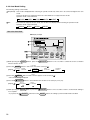
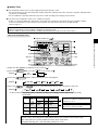
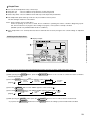
IV. Easy Maintenance Function (For Mr.SLIM P series)
● Reduces maintenance work drastically.
● Enables you to check operation data of the indoor and outdoor units by remote controller.
Furthermore, use of maintenance stable-operation control that fixes the operating frequency, allows smooth inspection, even for
inverter models.
Smooth Maintenance Function
Discharge temperature 147˚F
● Conventional inspection work
●Outdoor unit ●
Remove the
service panel.
●Indoor unit ●
Measure
the intake air
temperature.
Easy maintenance information (unit)
Compressor
Accumulated operating
time ( 10 hours)
Number of ON/OFF
times ( 10 times)
Operating
current (A)
Outdoor unit
Indoor unit
Heat exchanger
temperature (˚F)
Discharge
temperature (˚F)
Outside air
temperature (˚F)
Measure the discharge
temperature.
Intake air
temperature (˚F)
Heat exchanger
temperature (˚F)
Filter operating
time* (Hours)
Measure the outside air
temperature
* The filter operating time is the time that has elapsed since the filter was reset.
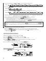
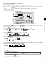
1. Maintenance Mode Operating Method
*
If you are going to use the "2.Guide for Operation Condition", set the airflow to "High" before activating maintenance mode.
● Switching to maintenance mode
Maintenance mode can be activated either when the air conditioner is operated or stopped.
It cannot be activated during test run.
Maintenance information can be viewed even if the air conditioner is stopped.
■ Remote controller button information
Outdoor unit information
Confirm
Operation mode
Activate/cancel maintenance mode
Compressor information
Indoor unit information
(1) Press the TEST button for three seconds to switch to maintenance mode.
[Display ] MAINTENANCE
If stable operation is unnecessary or if you want to check the data with the air conditioner stopped, skip to step (4).
● Fixed Hz operation
The operating frequency can be fixed to stabilize operation of inverter model.
If the air conditioner is currently stopped, start it by this operation.
(2) Press the
[Display
MODE button to select the desired operation mode.
]
Stable cooling
operation
Stable heating
operation
Stable operation
cancellation
COOL
STABLE MODE
HEAT
STABLE MODE
STABLE MODE
CANCEL
(3) Press the FILTER ( ) button to confirm the setting.
[Display
] Waiting for stabilization
Stabilized
After 10 to 20 minutes
6
● Data measurement
When the operation is stabilized, measure operation data as explained below.
(4) Press the [TEMP] buttons (
[Screen
and
) to select the desired refrigerant address.
]
(5) Select the type of data to be displayed.
After selecting, go to step (6).
Compressor information
MENU button
Cumulative
operation time
]
ON/OFF Number
COMP ON
x10 HOURS
COMP ON
x100 TIMES
Operating current
COMP ON
CURRENT (A)
IV. Easy Maintenance Function (For Mr. SLIM P series)
[Display
Outdoor unit information
ON/OFF button
[Display
Heat exchanger
temperature
]
OUTDOOR UNIT
H.EXC. TEMP
Comp discharge
temperature
Outdoor ambient
temperature
OUTDOOR UNIT
OUTLET TEMP
OUTDOOR UNIT
OUTDOOR TEMP
Indoor unit information
button
[Display
Heat exchanger
temperature
Indoor room
temperature
]
INDOOR UNIT
INLET TEMP
INDOOR UNIT
H.EXC. TEMP
Filter operating
time
INDOOR UNIT
FILTER USE H
(6) Press the FILTER ( ) button to confirm the setting.
[Display example for accumulated operating time]
Blinking
Display
Waiting for response
After approx.
10 seconds
12,340 hours
(7) Data is displayed on the display (at ).
To check the data for each item, repeat steps (5) to (7).
(8) To cancel maintenance mode, press the
TEST
button for three seconds or press the
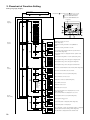
■ Refrigerant address
Single refrigerant system
ON/OFF button.
Multi refrigerant system (group control)
In the case of single refrigerant system, the refrigerant address
is "00" and no operation is required.
Simultaneous twin units belong to this category
(single refrigerant system).
[1:1]
Refrigerant
address=00
[Twin]
Refrigerant
address=00
Outdoor
unit
Outdoor
unit
Indoor unit
01
Indoor unit
01
Remote
controller
Remote
controller
Indoor unit
02
Up to 16 refrigerant systems (16 outdoor units) can be connected as a group by one remote controller. To check or set the
refrigerant addresses.
Refrigerant
address
00
Outdoor
unit
Refrigerant
address
01
Outdoor
unit
Refrigerant
address
02
Outdoor
unit
Refrigerant
address
15
Outdoor
unit
Indoor unit
01
Indoor unit
01
Indoor unit
01
Indoor unit
01
Remote
controller
7
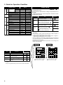
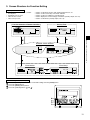
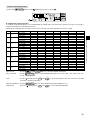
2. Guide for Operation Condition
Check Points
Outdoor Unit
Good
Retightened
Indoor Unit
Good
Retightened
(Insulation resistance)
M
(Voltage)
CleanliTemperature
ness
Times
Current
A
Refrigerant/heat exchanger temperature
COOL
˚F HEAT
˚F
Refrigerant/discharge temperature
Air/outside air temperature
COOL
˚F HEAT
˚F
COOL
˚F HEAT
˚F
(Air/discharge temperature)
COOL
˚F HEAT
˚F
Appearance
Good
Cleaning required
Heat exchanger
Good
Cleaning required
Sound/vibration
None
Present
Temperature
Cleanliness
Outdoor Unit
Time
Number of ON/OFF times
pressor
Indoor Unit
V
Accumulated operating time
Com-
Enter the temperature differences between , , and into
the graph given below.
Operation state is determined according to the plotted areas on
the graph.
For data measurements, set the fan speed to "Hi" before activating maintenance mode.
Inspection
COOL
˚F HEAT
˚F
(Air/discharge temperature)
COOL
˚F HEAT
˚F
Refrigerant/heat exchanger temperature COOL
˚F HEAT
˚F
difference
Good
Cleaning required
Filter
Good
Cleaning required
Fan
Good
Cleaning required
Heat exchanger
Good
Cleaning required
Sound/vibration
None
Present
Discharge temperature) - (
Filter may be clogged. *1
Inspection A
Performance has dropped. Detailed inspection is necessary.
Inspection B
Refrigerant amount is dropping.
Inspection C
Filter or indoor heat exchanger may be
clogged.
*
8
The above judgement is just guide based on Japanese standard
conditions.
It may be changed depending on the indoor and outdoor temperature.
˚F
Is "000" displayed stably in Display D
on the remote controller?
Temperature (
difference
( Indoor intake air temperature) - ( Indoor
heat exchanger temperature)
Normal operation state
Filter inspection
Heat
Result
Normal
˚F
Discharge temperature) - (
Stable Unstable
Indoor
˚F
heat exchanger temperature)
(
Indoor heat exchanger temperature) -
(
Indoor intake air temperature)
˚F
* Fixed Hz operation may not be possible under the following temperature ranges.
A)In cool mode, outdoor intake air temperature is 104 ˚F or higher or
indoor intake air temperature is 73 ˚F or lower
B)In heat mode, outdoor intake air temperature is 68 ˚F or higher or
indoor intake air temperature is 77 ˚F or lower
* If the air conditioner is operated at a temperature range other than the
ones above but operation is not stabilized after 30 minutes or more have
elapsed, carry out inspection.
* In heat mode, the operation state may vary due to frost forming on the
outdoor heat exchanger.
Judgment
Cool
Outdoor
Indoor intake air temperature) - (
Cool mode
Check item
Stable Unstable
heat exchanger temperature)
(
* The filter operating time is the time that has elapsed since the filter was reset.
Area
Result
Indoor heat exchanger temperature)
Time
Decorative panel
Item
Is "000" displayed stably in Display
on the remote controller?
Temperature (
Inspection
Air/intake air temperature
Filter operating time*
Classification
Heat mode
˚F
˚F
81
72
Inspection C
63
54
45
36
Filter inspection
Normal
27
18
Inspection B
Inspection A
9
0 18 36 54 72 90 108 126 144˚F
[ Discharge temperature] - [
heat exchanger temperature)
Outdoor
Indoor heat exchanger temperature) Indoor intake air temperature)
Retightened
(
(
Good
Cool
Terminal block
Result
Breaker
Heat
Power supply
Loose connection
Inspection item
81
72
Inspection C
Filter inspection
63
54
45
Normal
36
27
18
Inspection B
Inspection A
9
18 36 54 72 90 108 126 144˚F
[ Discharge temperature] - [
heat exchanger temperature)
Indoor
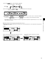
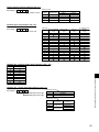
V. How to Select Functions of remote controller
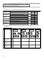
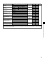
1. Function Items
The setting of the following remote controller functions can be changed using the remote controller function selection mode.
Change the setting when needed.
Item 2
Item 1
Language setting to display
1.Change Language
("CHANGE LANGUAGE")
(1) Operation function limit setting (operation lock) ("LOCKING FUNCTION")
2.Function limit
("FUNCTION SELECTION") (2) Use of automatic mode setting ("SELECT AUTO MODE")
(3) Temperature range limit setting ("LIMIT TEMP FUNCTION")
3.Mode selection
(1) Remote controller main/sub setting ("CONTROLLER MAIN/SUB")
("MODE SELECTION")
(2) Use of clock setting ("CLOCK")
(3) Timer function setting ("WEEKLY TIMER")
(4) Contact number setting for error situation ("CALL.")
(1) Temperature display /˚F setting ("TEMP MODE /˚F")
4.Display change
("DISP MODE SETTING") (2) Room air temperature display setting ("ROOM TEMP DISP SELECT")
(3) Automatic cooling/heating display setting ("AUTO MODE DISP C/H")
Item 3 (Setting content)
Display in multiple languages is possible.
Setting the range of operation limit (operation lock)
Setting the use or non-use of "automatic" operation mode
Setting the temperature adjustable range (maximum, minimum)
Selecting main or sub remote controller
* When two remote controllers are connected to one group, one controller must be set to sub.
Setting the use or non-use of clock function
Setting the timer type
Contact number display in case of error
Setting the telephone number
Setting the temperature unit ( or ˚F) to display
Setting the use or non-use of the display of indoor (suction) air temperature
Setting the use or non-use of the display of "Cooling" or "Heating" display during
operation with automatic mode
[Detailed setting]
[4] -1. CHANGE LANGUAGE setting
The language that appears on the dot display can be selected.
Japanese (JP), English (GB), German (D), Spanish (E),
Russian (RU), Italian (I), Chinese (CH), French (F)
[4] -2. Function limit (FUNCTION SELECTION)
(1) Operation function limit setting (operation lock)(LOCKING FUNCTION)
no1 : Operation lock setting is made on all buttons other than
the [ ON/OFF] button.
no2 : Operation lock setting is made on all buttons.
OFF (Initial setting value) : Operation lock setting is not made
* To make the operation lock setting valid on the normal screen, it is
necessary to press buttons (Press and hold down the [FILTER]
and [ ON/OFF] buttons at the same time for two seconds.) on
the normal screen after the above setting is made.
.
(2) Use of automatic mode setting
When the remote controller is connected to the unit that has automatic operation mode, the following settings can be made.
ON (Initial setting value) : The automatic mode is displayed when
the operation mode is selected.
OFF
: The automatic mode is not displayed
when the operation mode is selected.
(3) Temperature range limit setting (LIMIT TEMP FUNCTION)
After this setting is made, the temperature can be changed within the set range.
LIMIT TEMP COOL MODE :
The temperature range can be changed on cooling/dry mode.
LIMIT TEMP HEAT MODE :
The temperature range can be changed on heating mode.
LIMIT TEMP AUTO MODE :
The temperature range can be changed on automatic mode.
OFF (initial setting) : The temperature range limit is not active.
* When the setting, other than OFF, is made, the temperature range limit setting
on cooling, heating and automatic mode is made at the same time. However
the range cannot be limited when the set temperature range has not changed.
To increase or decrease the temperature, press the [ TEMP ( ) or ( )] button.
To switch the upper limit setting and the lower limit setting, press the [
]
button. The selected setting will blink and the temperature can be set.
Settable range
Cooling/Dry mode : Lower limit: 19 ~ 30 , 67˚F~87˚F
Upper limit: 30 ~ 19 , 87˚F~67˚F
Heating mode :
Lower limit: 17 ~ 28 , 63˚F~83˚F
Upper limit: 28 ~ 17 , 83˚F~63˚F
Automatic mode : Lower limit: 19 ~ 28 , 67˚F~83˚F
Upper limit: 28 ~ 19 , 83˚F~67˚F
[4] -3. Mode selection setting
(1) Remote controller main/sub setting(MODE SELECTION)
Main : The controller will be the main controller.
Sub : The controller will be the sub controller.
(2) CLOCK setting
ON : The clock function can be used.
OFF : The clock function cannot be used.
(3) Timer function setting
WEEKLY TIMER (initial setting):
The weekly timer can be used.
AUTO OFF TIMER: The auto off timer can be used.
SIMPLE TIMER :
The simple timer can be used.
TIMER MODE OFF: The timer mode cannot be used.
* When the use of clock setting is OFF, the "WEEKLY TIMER" cannot be
used.
(4) Contact number setting for error situation
CALL OFF: The set contact numbers are not displayed in case of error.
CALL **** *** **** : The set contact numbers are displayed in case
of error.
CALL_
: The contact number can be set when the display is as
shown on the left.
Setting the contact numbers
To set the contact numbers, follow the following procedures.
Move the blinking cursor to set numbers. Press the [ TEMP. ( ) and
( )] button to move the cursor to the right (left). Press the [ CLOCK
( ) and ( )] button to set the numbers.
[4] -4. Display change setting(DISP MODE SETTING)
(1) Temperature display / ˚F setting
: The temperature unit is used.
˚F : The temperature unit ˚F is used.
(2) Room air temperature display setting(ROOM TEMP DISP SELECT)
ON : The room air temperature is displayed.
OFF : The room air temperature is not displayed.
(3) Automatic cooling/heating display setting(AUTO MODE DISP C/H)
ON : One of "Automatic cooling" and "Automatic heating" is displayed
under the automatic mode is running.
OFF : Only "Automatic" is displayed under the automatic mode.
9
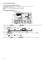
V. How to Select Functions of remote controller
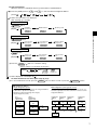
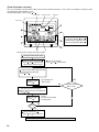
[Function selection flowchart] Refer to next page.
[1] Stop the air conditioner to start remote controller function selection mode. ➔ [2] Select from item1. ➔ [3] Select from item2. ➔ [4] Make the setting.
(Details are specified in item3) ➔ [5] Setting completed. ➔ [6] Change the display to the normal one. (End)
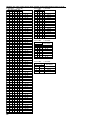
2. Flowchart of Function Setting
Setting language (English)
Normal display
(Display when the air condition is not running)
Hold down the
button and press the
Hold down the
button and press the
button for 2 seconds.
Remote controller function selection mode
Item1
Change
Language
button for 2 seconds.
Press the operation mode button.
Press the TIMER MENU button.
Press the TIMER ON/OFF button.
Item2
Dot display
EN
GE
ES
TEMP.
ON/OFF
RU
MENU
BACK
IT
MONITOR/SET
PAR-21MAA
ON/OFF
FILTER
DAY
CLOCK
CHECK TEST
OPERATION
CLEAR
ZH
FR
JA
Function
selection
Item3
Operation lock setting is not used.
(Initial setting value)
OFF
no1
Operation lock setting for all buttons except ON/OFF is
active.
no2
Operation lock setting for all buttons is active.
ON
The automatic mode is displayed when the operation mode is
selected. (Initial setting value)
OFF
The automatic mode is not displayed when the operation mode
is selected.
OFF
The temperature range limit is not active. (Initial setting value)
The temperature range can be changed on cooling/dry mode.
The temperature range can be changed on heating mode.
The temperature range can be changed on automatic mode.
Mode
selection
The remote controller will be the main controller. (Initial setting value)
The remote controller will be the sub controller.
ON
The clock function can be used. (Initial setting value)
OFF
One of the
description
marked *
on the right
will be
displayed.
(current
setting)
Display
mode setting
10
The clock function can not be used.
*
Weekly timer can be used. (Initial setting value)
*
Auto off timer can be used.
*
Simple timer can be used.
*
Timer mode can not be used.
OFF
The set contact numbers are not displayed in case of error.
(Initial setting value)
CALL-
The set contact numbers are displayed in case of error.
˚F
The temperature unit ˚F is used. (Initial setting value)
˚C
The temperature unit
ON
Room air temperature is displayed. (Initial setting value)
OFF
Room air temperature is not displayed.
ON
One of "Automatic cooling" and "Automatic heating" is displayed
under the automatic mode is running. (Initial setting value)
OFF
Only "Automatic" is displayed under the automatic mode.
is used.
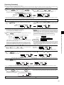
3. Screen Structure for Function Setting
Description of each screen
Function selection of remote controller
Set day time
Standard control screen
Timer monitor screen
Timer set up screen
:
:
:
:
:
Used to set the timer function and operation limit function, etc.
Used to set the current day of the week and time.
Used to set the air conditioner’s operating state.
Used to display the current settings of the timers (weekly, simple, auto off).
Used to set the timers (weekly, simple, auto off).
Function Selection of Remote Controller
Set Day Time
V. How to Select Functions of remote controller
•
•
•
•
•
Standard Control Screens
˚F
˚F
(OFF)
(ON)
Timer Monitor
Timer Setup
˚F
How to change the screen display
:
:
:
:
Press the [ON/OFF] button for two seconds while holding down the [MODE] button.
Press the [MENU] button.
Press the [MODE] (BACK) button.
Press the [CLOCK] buttons ( and ).
11
4. Function Setting Mode
4.1 Change Language
The language that appears on the dot display can be selected.
The following languages can be selected.
English (GB)
German (D)
Spanish (E)
Russian (RU)
Italian (I)
Chinese (CH)
French (F)
Japanese (JP)
Changing the Display Language
■ Display example
(1)(4)
(2)
(3)
(1) While pressing the
selection mode.
CHANGE
LANGUAGE
]
]
[English]
LANGUAGE
ENGLISH(GB)
[Japanese]
LANGUAGE
(JP)
(4) While pressing the
complete.
[German]
LANGUAGE
Deutsch(D)
[French]
LANGUAGE
FRENCH(F)
MODE button, press the
Display English
example
(Cool mode) Italian
12
FUNCTION
SELECTION
).
MODE
SELECTION
DISP MODE
SETTING
MENU button to select the desired display language.
(3) Press the
[Display
ON/OFF button for two seconds to activate the remote controller’s function
MODE button until CHANGE
LANGUAGE appears on the screen (at
(2) Press the
[Display
MODE button, press the
[Spanish]
LANGUAGE
ESPAÑOL(E)
[Russian]
LANGUAGE
pycck(RU)
[Chinese]
LANGUAGE
(CH)
[Italian]
LANGUAGE
ITALIANO(I)
ON/OFF button for two seconds to return to normal mode. Setting is now
German
Spanish
Russian
Chinese
French
Japanese
V. How to Select Functions of remote controller
Multi Language Display
13
4.2 Function Setting
4.2.1 Operation Lock (Operation Function Limit Setting)
The following settings can be made.
no1
:All buttons except for the [ON/OFF] button are locked.
no2
:All buttons are locked.
OFF (default) :No buttons are locked.
*
To activate this operation lock function on the normal screen, hold down the
holding down the FILTER ( ) button.
ON/OFF button for two seconds while
How to Lock the Buttons
■ Display example
(6)(7)
(1)(5)
(2)
(3)
(4)
(1) While pressing the MODE
function selection mode.
(2) Press the
[Display
ON/OFF button for two seconds to activate the remote controller’s
FUNCTION
MODE button to select SELECTION on the screen (at
CHANGE
LANGUAGE
]
FUNCTION
SELECTION
).
MODE
SELECTION
DISP MODE
SETTING
MENU button until “LOCKING FUNCTION” appears on the screen (at
(3) Press the
[Display
button, press the
LOCKING
FUNCTION
]
SELECT
AUTO MODE
).
LIMIT TEMP
FUNCTION
* Displays the mode that is set in “Temperature Range Limit Setting”.
ON/OFF button until the desired lock mode appears on the screen (at
(4) Press the
[Display
]
(5) While pressing the
now complete.
No limitation
Lock All Except
ON/OFF
MODE button, press the
Lock All Buttons
ON/OFF button for two seconds to return to normal mode. Setting is
Completing steps (1) to (5) allows use of the operation lock function.
To enable the lock function, carry out the following steps.
14
).
Enabling the Lock Function
(6) While pressing the FILTER ( ) button, press the
function.
).
FUNCTION appears on the screen (at
ON/OFF
button for two seconds to enable the operation lock
* If a locked button is pressed while the operation lock function is in use, FUNCTION will blink on the screen (at
).
■ Display example when operation lock function is in use
How to Unlock the Buttons
(7) While pressing the FILTER ( ) button, press the
).
V. How to Select Functions of remote controller
FUNCTION disappears from the screen (at
ON/OFF button for two seconds.
■ Display example when the operation lock function is not in use
15
4.2.2 Auto Mode Setting
The following settings can be made.
ON (default) : Auto mode is displayed when selecting an operation mode only if the unit to be connected supports the auto
mode.
However, this does not apply if the unit to be connected does not support the auto mode.
Operation mode can be switched:
COOL
OFF
DRY
FAN
AUTO
HEAT
: Even if the unit supports the auto mode, auto mode is not displayed when selecting an operation mode.
Operation mode can be switched :
COOL
DRY
FAN
HEAT
How to Set Auto Mode
■ Display example
(1) While pressing the
MODE button, press the
ON/OFF button for two seconds to activate the remote controller’s
function selection mode.
(2) Press the MODE
[Display
FUNCTION
button to select SELECTION on the screen (at
CHANGE
LANGUAGE
]
FUNCTION
SELECTION
SELECT
).
MODE
SELECTION
(3) Press the
MENU button so that AUTO MODE appears on the screen (at
* The current setting is displayed.
).
ON/OFF button to select whether auto mode is to be used (on) or not (off).
(4) Press the
[Display
DISP MODE
SETTING
]
(5) While pressing the
SELECT
AUTO MODE
SELECT
AUTO MODE
MODE button, press the
ON/OFF button for two seconds to return to normal mode. Setting is
now complete.
* If you press the
16
ON/OFF button before the MODE button, the settings you have made will be cancelled.
● Screen display when auto mode is set to ON
ON/OFF button.
(1) Press the
The ON lamp lights up and operating contents are displayed on the LCD.
(2) Press the MODE
button.
Each time the MODE
COOL
button is pressed, the operation mode switches from one to another. “AUTO” is also displayed.
DRY
FAN
AUTO
*1
HEAT
*1
*1: If the remote controller is connected with the unit for cool operation only, “AUTO” and “HEAT” will not be displayed, nor will
it be possible to select them.
If AUTO MODE DISP C/H is ON (see 4.4.3), it takes about 10 seconds before the
display is switched from one mode to another.
● Screen display when auto mode is set to OFF
(1) Press the
ON/OFF button.
The ON lamp lights up and operating contents are displayed on the LCD.
(2) Press the MODE
button.
Each time the MODE
COOL
button is pressed, the operation mode switches from one to another, but “AUTO” is not displayed.
DRY
FAN
HEAT
*1
*1: If the remote controller is connected with the unit for cool operation only, “HEAT” will not be displayed.
17
V. How to Select Functions of remote controller
■ Display example when auto mode is set to ON
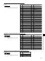
4.2.3 Temperature Range Limit Setting
The temperature setting range can be limited.
It can be limited for each mode.
Cool mode : The temperature setting range for cool/dry mode can be changed.
Heat mode : The temperature setting range for heat mode can be changed.
Auto mode : The temperature setting range for auto mode can be changed.
OFF (default) : The temperature setting range is not limited.
*
When a mode other than OFF mode is set, temperature setting range limit setting for cool, heat and auto modes will be made
simultaneously.
However, limit setting will not be made unless the range has been changed.
Setting range
Standard setting
Lower limit
67 °F – 87 °F
67 °F – 87 °F
Upper limit
87 °F – 67 °F
HEAT Mode
Lower limit
63 °F – 83 °F
63 °F – 83 °F
Upper limit
83 °F – 63 °F
AUTO Mode
Lower limit
67 °F – 83 °F
67 °F – 83 °F
Upper limit
83 °F – 67 °F
* Temperatures can be set within the range of “upper limit ” “lower limit”.
COOL·DRY Mode
Limiting the Temperature Range
■ Display example
(1) While pressing the MODE
function selection mode.
(2) Press the MODE
[Display
]
button, press the
ON/OFF button for two seconds to activate the remote controller’s
FUNCTION
button to select SELECTION on the screen (at
CHANGE
LANGUAGE
FUNCTION
SELECTION
).
MODE
SELECTION
TEMP
MENU button to select LIMIT
FUNCTION on the screen (at
(3) Press the
DISP MODE
SETTING
).
* If a setting change was made previously, the mode that was set (one of the modes shown in step (4)) will be displayed.
ON/OFF button to select the mode for which temperature range limit setting is to be made.
(4) Press the
[Display
]
DRY mode
COOL mode
HEAT mode
AUTO mode*
No limitation
LIMIT TEMP
COOL MODE
LIMIT TEMP
HEAT MODE
LIMIT TEMP
AUTO MODE
LIMIT TEMP
FUNCTION
Display
* No operation modes will be displayed if auto mode has been set to OFF.
18
(5) Press the
button to select lower limit or upper limit.
Lower limit blinks.
[Display
Upper limit blinks.
]
(6) Press the [TEMP] buttons (
and
) to set the desired temperature setting range.
[Setting example for lower limit]
Display
MODE button, press the
ON/OFF button for two seconds to return to normal mode. Setting is
ON/OFF button before the MODE button, the settings you have made will be cancelled.
* If an attempt is made to set a temperature outside the range when the temperature range limit function is in use, “LIMIT
TEMP FUNCTION” will blink.
■ Display example when the temperature range limit function is in use
If employees tend to lower the temperature excessively in the office without permission, set the temperature setting range for
cool/dry mode to 77 °F-87 °F.
Setting
Even if someone who feels hot tries to press remote the controller’s
buttons to lower the temperature below 76 °F, or lower…
LIMIT TEMP
FUNCTION
blinks and the command is not accepted.
19
V. How to Select Functions of remote controller
(7) While pressing the
now complete.
* If you press the
4.3 Basic Functions Setting
4.3.1 Remote Controller Main/Sub Setting
When using two remote controllers, they must be designated as the main and sub remote controllers.
The following settings can be made.
MAIN (default) : The remote controller is set as the main controller.
SUB
: The remote controller is set as the sub controller.
To Change the Main/Sub Setting
■ Display example
(1)(5)
(2)
(3)
(4)
(1) While pressing the
MODE button, press the
ON/OFF button for two seconds to activate the remote controller’s
function selection mode.
(2) Press the MODE
[Display
]
MODE
button until SELECTION appears on the screen (at
CHANGE
LANGUAGE
FUNCTION
SELECTION
).
MODE
SELECTION
DISP MODE
SETTING
(3) Press the
MENU button to select “CONTROLLER” on the screen (at
(4) Press the
ON/OFF button to select “CONTROLLER MAIN” or “CONTROLLER SUB” on the screen (at
[Display
]
CONTROLLER
MAIN
(5) While pressing the MODE
20
).
).
CONTROLLER
SUB
button, press the
ON/OFF button for two seconds to return to normal mode.
4.3.2 Timer function setting (Weekly timer/Auto off timer/Simple timer)
The following settings can be made.
Weekly Timer (default) : The weekly timer can be used.
Auto Off Timer
: The auto off timer can be used.
Simple Timer
: The simple timer can be used.
Timer Mode Off
: Timer mode cannot be used.
* If the clock function is disabled (OFF), “Weekly Timer” cannot be selected.
■ Clock function setting
The following settings can be made.
ON (default) : The clock function can be used.
OFF
: The clock function cannot be used.
* If “OFF” is selected to disable the clock function, the weekly timer cannot be used to make day of the week/time settings.
To use the weekly timer to set the day of the week and time, the clock function must be set to “ON” (default).
To Use the Clock
(1)(5)
(2)
(3)
(4)
(1) While pressing the
MODE button, press the
ON/OFF button for two seconds to activate the remote controller’s
function selection mode.
(2) Press the MODE
[Display
MODE
button until SELECTION appears on the screen (at
CHANGE
LANGUAGE
]
FUNCTION
SELECTION
).
MODE
SELECTION
(3) Press the
MENU button to select “CLOCK” on the screen (at
(4) Press the
ON/OFF button so that “ON” appears on the screen (at
[Display
DISP MODE
SETTING
).
).
]
(5) While pressing the MODE
* If you press the
button, press the
ON/OFF button for two seconds to return to normal mode.
ON/OFF button before the MODE button, the settings you have made will be cancelled.
■ Day of the week and time setting
● The day of the week and time can be set and changed.
[The time can be set in 1-minute increments.]
Notes
• This setting is not possible if the clock function is disabled by the function setting.
• The day of the week and time are not displayed if the clock function is disabled by function selection.
• This setting is not possible if the simple timer or auto off timer has been selected.
21
V. How to Select Functions of remote controller
■ Display example
Setting the Day of the Week and Time
■ Display example
(4)
(2)
(5)
(1)(3)
(1) Press the [CLOCK] buttons (
) to display
TIME SET
:ENTER
on the screen (at
).
ON/OFF button until the desired day of the week appears.
(2) Press the
[Display
and
]
Sun
Mon
Tue
Wed
Thu
Fri
Sat
(3) Press the [CLOCK] buttons (
and
) to set the desired time.
Press the [CLOCK] buttons (
and
) longer will switch the time in 10-minute and 1-hour increments.
[Display
]
One-minute
Ten-minute
One hour
(4) Press the FILTER ( ) button to confirm the time.
Note
The time you have set can be cancelled by pressing the MODE
(BACK) button without confirming it.
(5) Press the MODE (BACK) button to return to the normal screen and complete the day of the week/time setting.
* The day of the week and time you have set are displayed on the normal screen.
22
Weekly Timer
■ The weekly timer allows you to set up to eight operations per day of the week.
• For each operation, you can set the ON (start) or OFF (stop) timer and temperature. The start timer, stop timer and temperature
can also be set individually.
• The air conditioner is operated at the times you have set and according to the settings you have made.
■ The time for the weekly timer can be set in 1-minute increments.
* If “OFF” is selected to disable the clock function, the weekly timer cannot be used to make day of the week/time settings.
To use the weekly timer to set the day of the week and time, the clock function must be set to “ON” (default).
(Refer to page 21.)
Note
With the weekly timer, it is not possible to designate an operation mode.
The air conditioner will be operated in the currently selected operation mode. (Cool, Dry, Heat or Auto)
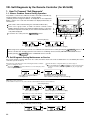
How to set the Weekly Timer
■ Display example (for
(7)
(6)
(3)(11)
(8)
V. How to Select Functions of remote controller
)
(10)
(2)
(5)
(4)
(1) Make sure that “WEEKLY” is displayed on the screen (at
MENU button to select
(2) Press the
[Display
TIMER
MONITOR
]
on the screen (at
).
TIMER SET
:ENTER
Sun-Sat
]
and
(4) Press the
[Display
).
ON/OFF button until the desired day of the week appears.
(3) Press the
[Display
TIMER SET
:ENTER
Sun
Mon
Fri
Sat
buttons to set the desired operation No. (Up to 8 patterns can be set.)
]
* A cell from the following setup matrix is selected according to the settings you have made in steps (2) and (3).
Set up Matrix
Op No.
no1
no2
Sunday
• 8:30
• ON
• 73 °F
• 10:00
• OFF
Monday
…
Saturday
- Setting contents Starts the air conditioner at 8:30 with the temperature set to 73 °F.
• 10:00
• OFF
• 10:00 • 10:00
• OFF • OFF
- Setting contents Stops the air conditioner at 10:00.
…
no8
Note
If “Sun – Sat” is set in step (3), the same pattern can be set for each day of the week at a time.
The same pattern is set in the shaded areas in the above setup matrix.
(Example: Selecting “Sun – Sat” and setting operation No. “no2”)
23
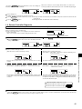
(5) Press the [CLOCK] buttons (
[Display
ON/OFF button to select whether to start or stop the air conditioner at the time you have set in step (5).
]
ON
OFF
(Space)
(7) Press the [TEMP] buttons (
[Display
) to set the desired time. (0:00 to 23:59)
]
(6) Press the
[Display
and
and
) to set the desired room temperature. (53 °F to 87 °F)
]
(Space)
Temperature setting range : The temperature can be set within a range of 53 °F to 87 °F. However, the setting range varies
with the type of the air conditioner. (Refer to 4-2-3.)
(8) After completing the settings in steps (4) to (7), press the FILTER ( ) button to confirm them.
To cancel the settings you have made, press the CHECK (CLEAR) button once.
* The time setting will change to “- -:- -”, and the ON/OFF and temperature settings will all disappear.
(To clear all the weekly timer settings you have made, hold down the
more until the settings blink. All of the settings will be cleared.)
CHECK (CLEAR) button for two seconds or
Note
The settings you have made can be cancelled by pressing the MODE (BACK) button befor pressing FILTER ( )
button.
When two or more different operations for the same time are set, only the operation with the larger operation No. will be
effective.
(9) Repeat step (3) to (8) to set the contents in the setup matrix.
(10) Press the MODE
(BACK) button to return to the normal screen and complete weekly timer setting.
ON/OFF button, the weekly timer will start and “
(11) If you press the
” will disappear from the screen.
” disappears.
Make sure that “
How to Review the Weekly Timer Settings
(1) Make sure that “WEEKLY” is displayed on the screen (at
).
(2) Press the
MENU button to display TIMER
MONITOR on the screen (at
(3) Press the
ON/OFF button to select the day of the week you want to check.
and
(4) Press the
).
buttons to switch the settings from one to another, one at a time.
* The settings are displayed in order of time setting.
TIMER
(5) To close the MONITOR and return to the normal screen, press the MODE
To Turn Off the Weekly Timer
(1) Press the
24
ON/OFF button to display
on the screen (at
).
button.
To Turn On the Weekly Timer
(1) Press the
ON/OFF button so that
disappears from the screen (at
).
● Weekly timer setting procedure
To facilitate weekly timer setting, it is recommended that the settings (day of the week, time, operation (on/off)) you are going to
make be entered in the setup table shown below.
Weekly timer setup table (up to 8 patterns can be set for each day of the week, 56 patterns in total for a week)
Operation No.
no 1
2
no 2
3
no 3
4
no 4
5
no 5
6
no 6
7
no 7
8
no 8
Monday
Tuesday
Wednesday
Thursday
Friday
Saturday
Operation No.
: Use the
Day of the week
: Use the
V. How to Select Functions of remote controller
1
Sunday
Time setting
On/off setting
Temperature
Time setting
On/off setting
Temperature
Time setting
On/off setting
Temperature
Time setting
On/off setting
Temperature
Time setting
On/off setting
Temperature
Time setting
On/off setting
Temperature
Time setting
On/off setting
Temperature
Time setting
On/off setting
Temperature
and
buttons to select the desired operation No.
ON/OFF button to select the desired day. (“Sun to Sat”, “Sun”, “Mon”, “Tue”, “Wed”, “Thu”, “Fri”
or “Sat” can be selected.)
Time
: Use the [
CLOCK] buttons (
and
) to set the desired time. (The time can be set from 0:00
to 23:59 in 1-minute increments.)
Operation (ON/OFF) : Use the
ON/OFF button to select the desired operation (ON,OFF,(space)).
Temperature
TEMP] buttons (
: Press the [
and
) to set the desired temperature.
25
2
Auto Off Timer
● The auto off timer begins counting down when the air conditioner starts, and stops the air conditioner when the set time
passed.
● The time on the auto off timer can be set in a range of 30 minutes to 4 hours, in 30-minute increments.
* By default, the weekly timer is selected as the remoter controller’s timer function.
To use the auto off timer, switch the timer function to the auto off timer using the remote controller’s function selection.
Note 1 : If the auto off timer is selected, it is not possible to use the weekly and simple timers.
Note 2 : Timer operation is not possible when:
A timer is operating, an error has occurred, the air conditioner is operating, the remote controller is diagnosing a
problem, function selection is in progress, timer setting is in progress, or the system is centrally controlled.
(ON/OFF operation is prohibited under the above conditions.)
Selecting the Auto Off Timer
■ Display example
(1)(5)
(2)
(3)
(4)
Steps (1) to (5) are necessary when switching the timer function from simple timer, weekly timer and no timer.
(1) While pressing the MODE
function selection mode.
(2) Press the MODE
[Display
MODE
FUNCTION
SELECTION
ON/OFF button until
]
TIMER MODE
OFF
(5) While pressing the MODE
* If you press the
AUTO OFF
TIMER
appears on the screen (at
AUTO OFF
TIMER
button, press the
).
MODE
SELECTION
MENU button so that “Timer” appears on the screen (at
(4) Press the
26
ON/OFF button for two seconds to activate the remote controller’s
button until SELECTION appears on the screen (at
CHANGE
LANGUAGE
]
(3) Press the
[Display
button, press the
SIMPLE
TIMER
DISP MODE
SETTING
).
).
WEEKLY
TIMER
ON/OFF button for two seconds to return to normal mode.
ON/OFF button before the MODE button, the settings you have made will be cancelled.
How to Set the Auto Off Timer
■ Display example
(3)
(5)
(4)
(1)
(2)
[Display
]
TIMER
MONITOR
(2) Press the [CLOCK] buttons (
).
V. How to Select Functions of remote controller
TIMER SET
MENU button for 3 seconds so that :ENTER appears on the screen (at
(1)Press the
TIMER SET
:ENTER
and
) to set the desired time.
(The time can be set up to 4 hours in 30-minute increments.)
[Display
]
(3) Press the FILTER ( ) button to confirm the setting.
(4) Press the MODE
button to complete the setting procedure.
[Set display example]
[Display
]
[Display
]
AUTO OFF
OFF
AFTER
Two hours
Checking the Current Auto Off Timer Setting
(1) Make sure that
(2) Press the
AUTO OFF
is displayed on the screen (at
MENU button for 3 seconds to display
TIMER
MONITOR
).
on the screen (at
).
• The time you have set is displayed.
TIMER
(3) To close the MONITOR and return to the normal screen, press the MODE
button.
■ Display example
27
To Turn Off the Auto Off Timer…
(1) Press the
ON/OFF button for 3 seconds so that the timer execution time disappears from the screen (at
• If the air conditioner is operated with the auto off timer turned OFF,
will appear on the screen (at
).
).
* The auto off timer will be effective the next time that the air conditioner is operated.
■ Display example (auto off timer is off)
To Turn On the Auto Off Timer…
(1) Press the
ON/OFF button for 3 seconds while the timer is OFF, so that
the timer execution time appears on the screen (at
).
* The timer execution time that was set previously will be displayed.
■ Display example (auto off timer is on)
28
disappears from the screen (at
) and
Simple Timer
■
●
●
●
You can set the simple timer in any of three ways.
Start time only
: The air conditioner starts when the set time has passed.
Stop time only
: The air conditioner stops when the set time has passed.
Start & Stop times : The air conditioner starts and stops at the respective passed times.
■ The simple timer (Start and stop) can be set only once within a 72-hour period.
The time setting is made in hour increments.
Note 1: Timer operation is not possible when:
A timer is operating, an error has occurred, the air conditioner is operating, the remote controller is diagnosing a problem, function selection is in progress, timer setting is in progress, or the system is centrally controlled.
(ON/OFF operation is prohibited under the above conditions.)
■ If the simple timer is not currently selected, select it and make the necessary changes to the current settings as explained
below.
Switching to the simple timer
V. How to Select Functions of remote controller
■ Display example
(1)(5)
(2)
(3)
(4)
Steps (1) to (5) are necessary when switching the timer function from auto off timer, weekly timer and no timer.
(1) While pressing the
MODE button, press the
ON/OFF button for two seconds to activate the remote controller’s
function selection mode.
(2) Press the MODE
MODE
button until SELECTION appears on the screen (at
CHANGE
LANGUAGE
[Display
FUNCTION
SELECTION
).
MODE
SELECTION
DISP MODE
SETTING
]
(3) Press the
MENU button so that “TIMER” appears on the screen (at
(4) Press the
ON/OFF button until “SIMPLE TIMER” appears on the screen (at
TIMER MODE
OFF
[Display
AUTO OFF
TIMER
SIMPLE
TIMER
).
).
WEEKLY
TIMER
]
(5) While pressing the MODE
* If you press the
button, press the
ON/OFF button for two seconds to return to normal mode.
ON/OFF button before the MODE button, the settings you have made will be cancelled.
29
How to Set the Simple Timer
■ Display example
(2)
(7)
(4)
(6)
(1)
(3)
Make sure that “SIMPLE TIMER” is displayed on the screen (at
TIMER SET
MENU button to select :ENTER on the screen (at
(1) Press the
[Display
).
TIMER
MONITOR
]
).
TIMER SET
:ENTER
ON/OFF button to select “Start time only” or “Stop time only”.
(2) Press the
Hr
AFTER
ON
Hr
AFTER
OFF
• Start time only (Displays the time at which the air conditioner starts) : “Hr AFTER ON”
• Stop time only (Displays the time at which the air conditioner stops) : “Hr AFTER OFF”
(3) Press the [ CLOCK] buttons (
increments.)
1
[Display
and
) to set the desired time. (The time can be set up to 72 hours in 1-hour
2
71
72
]
* To cancel the time you have set, press the
CHECK (CLEAR) button.
(4) Press the FILTER ( ) button to confirm the setting.
*1. When using only the start timer or stop timer, make sure that “– –” is displayed for the timer you are not going to use.
*2. To cancel the time you have set, press the
button to confirm it.
CHECK (CLEAR) button to display “– –”, and then press the FILTER ( )
(5) When using both the start and stop timers, carry out steps (2) to (4) to set both the start and stop times.
* It is not possible to set the same time for both the start and stop times.
(6) Press the MODE
button to complete the setting procedure.
[Set display example]
[Display
]
Hr
AFTER
ON
[Display
]
SIMPLE
Ten hours
(7)Press the
displayed.
ON/OFF button. The simple timer will start to operate and the timer execution time you have set will be
If both start and stop timers are set, whichever time will come first will be displayed.
30
Review the Current Simple Timer Settings
(1) Be sure that the “SIMPLE” indicator is displayed on the screen (at
).
TIMER
MONITOR
(2) Press the
appears on the screen (at
MENU button, so that the
• The time you have set to start or stop the timer appears on the screen (at
(3) Press the MODE
).
).
TIMER
button to close the MONITOR display and return to the standard control screen.
To Turn Off the Simple Timer…
ON/OFF button so that the timer setting no longer appears on the screen (at
).
V. How to Select Functions of remote controller
(1) Press the
Examples
1 Start timer operation : Operation starts 2 Stop timer operation : Operation stops
after 2 hours.
after 10 hours.
4 When both the start and stop timers are set
Example 1 : To activate the on timer first
Time set for the on timer: ON after 3 hours
Time set for the off timer: OFF after 7 hours
Timer start
Displays the time set for
the start timer.
After 3 hours
Displays “stop time” – “start time”.
Example 2 : To activate the off timer first
Time set for the off timer: OFF after 2 hours
Time set for the on timer: ON after 5 hours
Timer start
Displays the time set for the
off timer.
After 2 hours
Displays on timer (5hr)·off timer (2hr)
3 Timer cancelled
Timer setting no longer appears
Once seven hours have elapsed, the
air conditioner will remain stopped
until an operation is performed.
After 7 hours
Once five hours have elapsed, the
air conditioner will continue operating
until an operation is performed.
After 5 hours
31
Timer Mode Off
Timer mode cannot be used.
■ Display example
(1)(5)
(2)
(3)
(4)
How to set the Timer mode Off
(1) While pressing the
MODE button, press the
ON/OFF button for two seconds to activate the remote controller’s
function selection mode.
MODE button until appears on the screen (at
(2) Press the
[Display
(4) Press the
]
TIMER MODE
OFF
(5) While pressing the MODE
* If you press the
32
FUNCTION
SELECTION
MODE
SELECTION
DISP MODE
SETTING
MENU button so that “TIMER” appears on the screen (at ).
ON/OFF button until “TIMER MODE OFF” appears on the screen (at
(3) Press the
[Display
CHANGE
LANGUAGE
]
).
AUTO OFF
TIMER
SIMPLE
TIMER
).
WEEKLY
TIMER
ON/OFF button for two seconds to return to normal mode.
ON/OFF button before the MODE button, the settings you have made will be cancelled.
button, press the
4.3.3 Contact Number Setting for Error Situation
The following settings can be made.
CALL • OFF (default) : The preset contact number is not displayed even when an error occurs.
CALL • ************
: The preset contact number is displayed when an error occurs. (The contact number can consist of up
to 12 digits.)
CALL • –
: The contact number is not set in default setting.It is displayed as shown on the left.
Setting the Contact Numbers
■ Display example
(5)
(2)
(3)
(4)
(5)
(1) While pressing the MODE
function selection mode.
(2) Press the MODE
[Display
ON/OFF button for two seconds to activate the remote controller’s
button, press the
button until appears on the screen (at
CHANGE
LANGUAGE
]
FUNCTION
SELECTION
CALL .
TIMER
]
CONTROLLER
DISP MODE
SETTING
).
CLOCK
ON/OFF button to select whether or not to show the contact number.
(4) Press the
Do not show
[Display
]
[Display
]
Show
CALL .
CALL .
and
(5) Press the [CLOCK] buttons (
) to set the desired contact number, one digit at a time. To move the input digit
and
position left or right, press the [TEMP] buttons (
[Display
).
MODE
SELECTION
MENU button until “CALL” appears on the screen (at
(3) Press the
[Display
(7)
]
0
1
).
9
Space
The contact number can contain up to 12 digits.
[When entering “012”]
[Display
] CALL • 012_
“0” Press the [CLOCK] button (
) once.
Each time a value is entered, press the [TEMP] button (
“1” Press the [CLOCK] button (
) twice.
“2” Press the [CLOCK] button (
) three times.
) to move the cursor to the next digit to the right.
33
V. How to Select Functions of remote controller
(1)(6)
(6) While pressing the MODE
* If you press the
(7) If you press the
ON/OFF button for two seconds to return to normal mode.
ON/OFF button before the MODE button, the settings you have made will be cancelled.
button, press the
CHECK (CLEAR) button, the contact number will be displayed for five seconds.
● Once the contact number has been set, the error code and contact number will be displayed alternately when an error
occurs.
Error Code
Indoor unit No.
(Alternating Display)
Indoor unit No.
34
Error Code
4.4 Display Change Setting
4.4.1 Temperature Display °F/°C Setting
The following settings can be made.
➀ °F(default) : Temperatures are displayed in Fahrenheit.
(Degrees F = 1.8 × degrees C + 32)
➁ °C
: Temperatures are displayed in Celsius.
(Degrees C = (Degrees F - 32) / 1.8)
Switching the Temperature Display Unit between °F and °C
(1)(5)
(2)
(3)
(4)
(1) While pressing the
MODE button, press the
ON/OFF button for two seconds to activate the remote controller’s
function selection mode.
(2) Press the MODE
[Display
DISP MODE
button until SETTING
CHANGE
LANGUAGE
]
appears on the screen (at
FUNCTION
SELECTION
).
MODE
SELECTION
DISP MODE
SETTING
(3) Press the
MENU button to select “TEMP MODE °C/°F” on the screen (at
(4) Press the
ON/OFF button to select “°F” or “°C”on the screen (at
[Display
]
F
(5) While pressing the MODE
* If you press the
).
).
C
button, press the
ON/OFF button for two seconds to return to normal mode.
ON/OFF button before the MODE button, the settings you have made will be cancelled.
■Temperature display example when “°F” is selected
■Temperature display example when “°C” is selected
35
V. How to Select Functions of remote controller
■ Display example
4.4.2 Room air Temperature Display Setting
The following settings can be made.
➀ ON (default) : The room air temperature is displayed.
➁ OFF
: The room air temperature is not displayed.
Setting the Room Air Temperature
■ Display example
(1)(5)
(2)
(3)
(4)
(1) While pressing the
MODE button, press the
ON/OFF button for two seconds to activate the remote controller’s
function selection mode.
(2) Press the MODE
[Display
DISP MODE
button until SETTING
CHANGE
LANGUAGE
]
appears on the screen (at
FUNCTION
SELECTION
).
MODE
SELECTION
DISP MODE
SETTING
(3) Press the
MENU button so that “ROOM TEMP DISP SELECT” appears on the screen (at
(4) Press the
ON/OFF button to select “on” or “oFF” on the screen (at
[Display
).
]
(5) While pressing the MODE
* If you press the
button, press the
ON/OFF button for two seconds to return to normal mode.
ON/OFF button before the MODE button, the settings you have made will be cancelled.
■ Room air temperature display example
when “ON” is selected
36
).
■ Room air temperature display example
when “OFF” is selected
4.4.3 Automatic Cooling/Heating Display Setting
•
This section explains how to set whether to display “COOL”/“HEAT” in auto mode. It will not be displayed if auto mode is set to
OFF.
➀ ON (default) : One of “Automatic cooling” and “Automatic heating” is displayed under the automatic mode is displayed.
➁ OFF
: Only “Automatic” is displayed under the automatic mode.
Selecting Whether to Display “COOL”/“HEAT” in Auto Mode
■ Display example
(2)
(3)
(4)
(1) While pressing the
MODE button, press the
ON/OFF button for two seconds to activate the remote controller’s
function selection mode.
(2) Press the MODE
[Display
DISP MODE
button until SETTING
CHANGE
LANGUAGE
]
appears on the screen (at
FUNCTION
SELECTION
).
MODE
SELECTION
DISP MODE
SETTING
(3) Press the
MENU button so that “AUTO MODE DISP C/H” appears on the screen (at
(4) Press the
ON/OFF button to select “on” or “oFF” on the screen (at
[Display
).
).
]
(5) While pressing the MODE
* If you press the
button, press the
ON/OFF button for two seconds to return to normal mode.
ON/OFF button before the MODE button, the settings you have made will be cancelled.
■ Display example when “AUTO MODE DISP C/H” is set to “ON”
[During auto (cool) mode]
[During auto (heat) mode]
■ Display example when “AUTO MODE DISP C/H” is set to “OFF”
37
V. How to Select Functions of remote controller
(1)(5)
VI. Unit Function Setting by the Remote Controller (for Mr. SLIM P Series)
Perform the following settings only to change the functions for Mr. Slim series.
(This setting is not possible with the City-Multi series.)
Each unit’s functions can be set by a remote controller. Setting of each unit’s functions is possible by remote controller only.
Table Functions Available (For details regarding initial settings and operation modes of each unit, refer to the unit installation
manual.)
(1) Itemised functions of the entire refrigerant system (select unit number 00)
Function
Power failure
automatic recovery
Settings
Not available
Available
(Approx. 4-minute wait-period after power is restored.)
Mode No. Setting No.
1
1
2
Average data from each indoor unit
Data from the indoor unit with remote controllers
Data from main remote controller
Not supported
LOSSNAY
Supported (Indoor unit does not intake outdoor air through LOSSNAY.)
connectivity
Supported (Indoor unit intakes outdoor air through LOSSNAY.)
230V
Power voltage
208V
Auto operating mode Auto energy-saving operation ON
*2
Auto energy-saving operation OFF
2 C [36 F](Normal)
Frost prevention
3 C [37 F]
temperature
Standard
Defrosting control
For high humidity
Indoor temperature
detecting *1
2
3
4
5
15
17
Check
Remarks
1
2
3
1
2
3
1
2
1
2
1
2
1
2
*1. Can be set only when a wired remote controller is used. This function cannot be set for floor type models.
When using two remote controllers (two-remote controller operation), the remote controller with a built-in sensor must be set as the main remote controller.
Meaning of "Function setting"
Mode No.02 : indoor temperature detecting
No Indoor temperature : ta
OUTDOOR
OUTDOOR
INDOOR
REMOTE
(MAIN)
No1. Average data of the
sensor on all the
indoor units
INDOOR
REMOTE
(SUB)
factory ta=(A+B)/2
setting
INDOOR
REMOTE
(MAIN)
INDOOR
REMOTE
(SUB)
OUTDOOR
OUTDOOR
INDOOR
INDOOR
REMOTE
(MAIN)
REMOTE
(SUB)
REMOTE
(MAIN)
ta=(A+B)/2
ta=A
ta=A
No2. the data of the sensor
on the indoor unit that
connected
with remote controller
ta=A
ta=B
ta=A
ta=A
No3 the data of the sensor
on main remote
controller.
ta=C
ta=C
ta=C
ta=C
*2. Can be set only when the outdoor unit is an inverter type.
38
(2) Itemised functions of the indoor unit (select unit numbers 01 to 03 or AL [Wired remote controller] / 07 Wireless remote controller])
Mode No.
07
08
09
10
11
12
23
24
25
27
28
Note
If a function of an indoor unit is changed by function selection after installation is complete, make sure that a “
column of Table to indicate the change
Setting No.
1
2
3
1
2
3
1
2
3
1
2
1
2
3
1
2
1
2
1
2
1
2
3
1
2
1
2
Check Remarks
” mark, etc., is given in the “Check”
39
VI. Unit Function Setting by the Remote Controller (for Mr. SLIM P series)
Settings
100Hr
Filter sign
2500Hr
"Clean the filter" indicator is not displayed.
Quiet
Standard
Air flow
High ceiling PLA-A·AA type
Standard
(Fan speed )
High ceiling
High ceiling
4 directions
No. of air outlets
3 directions
of PLA-A·AA
2 directions
Installed options
Not supported
(highperformance filter)
Supported
No vanes(Vane No.3 setting : PLA-A·AA only)
Vane No. 1 setting
Vane setting
Vane No. 2 setting
OFF
Energy saving air
ON
flow (Heating mode)
Not available
Swing
Available
Set temperature in
ON
OFF
heating mode 4deg-up
Extra low
Fan speed when the
Stop
heating thermostat is OFF
Keeping fan speed set by remote controller
Keeping fan speed set by remote controller
Fan speed when the
cooling thermostat is OFF Stop
Detection of abnormality
Detect
(P8) of the pipe temperature Neglect
Function
[Flow of function selection]
First, try to familiarize yourself with the flow of the function selection procedure. In this section, an example of setting the room
temperature detection position is given.
For actual operations, refer to steps
to .
Setting number
Refrigerant address
Unit number
Mode number
Modes 01 to 14 can be activated
by pressing buttons
and
simultaneously, and modes 15 to
28 by pressing buttons and .
Selecting functions using the wired remote controller
Check the function selection setting.
Switch to function setting mode.
(Press and at the same time
with the remote controller stopped.)
For modes 15 and higher,
press and at the same time.
Specify refrigerant address 00 (outdoor unit)
Specify unit No. 00. (indoor unit)
(Use and .)
Enter the setting.
(Press .)
YES
(Specified indoor unit:
FAN operation)
NO
Select mode No. 02
(room temperature detection position).
Select setting No. 03 (remote controller fixed).
(Use and .)
Enter the setting.
(Press .)
Change refrigerant
address unit No.
Example:
Selecting room temperature
detection position
NO
Finished
YES
Ending function display
(Press and at the same time.)
The above procedure must be carried out only if changes are necessary.
40
[Operating Procedure]
Check the setting items provided by function selection.
If settings for a mode are changed by function selection, the functions of that mode will be changed accordingly. Check all the current settings according to steps
to , fill in the "Check" column in Table, and then change them as necessary. For factory settings, refer to the indoor unit's installation manual.
Switch off the remote controller.
Hold down the FILTER
( (
mode is 15 to 28)and
Set the outdoor unit's refrigerant address.
Press the [ CLOCK] buttons (
and
) to select the desired
refrigerant address. The refrigerant address changes from "00" to "15".
(This operation is not possible for single refrigerant systems.)
TEST
buttons simultaneously for atleast two seconds. FUNCTION
SELECTION will start to blink,
and then the remote controller's display content will change as shown below.
Refrigerant address
display section
blinked for two seconds or "88" blinks in the room temperature display area for two seconds, a transmission error may have occurred.
* If the unit stops after FUNCTION
SELECTION
Check to see if there are any sources of noise or interference near the transmission path.
Note
If you have made operational mistakes during this procedure, exit function selection (see step
Set the indoor unit number.
Press the
area.
), and then restart from step
.
and
) to select the unit number
Press the [ CLOCK] buttons (
of the indoor unit for which you want to perform function selection. The unit
number changes to "00", "01", "02","03",04" and "AL" each time a button is
pressed.
ON/OFF button so that "- -" blinks in the unit number display
Unit number
display section
* To set modes 01 to 06 or 15 to 22 select unit number "00".
* To set modes 07 to 14 or 23 to 28 carry out as follows:
To set each indoor unit individually, select "01" to "04".
To set all the indoor units collectively, select "AL".
When the refrigerant address and unit number are confirmed by pressing the
MODE button, the corresponding indoor unit will start fan operation. This
helps you find the location of the indoor unit for which you want to perform function
selection. However, if "00" or "AL" is selected as the unit number, all the indoor
units corresponding to the specified refrigerant address will start fan operation.
Confirm the refrigerant address and unit number.
Press the MODE button to confirm the refrigerant address and unit
number.
After a while, "- - " will start to blink in the mode number display area.
00 refrigerant address
Outdoor unit
Mode number
display section
*
VI. Unit Function Setting by the Remote Controller (for Mr. SLIM P series)
Example) When the refrigerant address is set to 00 and the unit number is 02.
Indoor unit
"88" will blink in the room temperature display area if the selected refrigerant
address does not exist in the system.
Furthermore, if "F" appears and blinks in the unit number display area and the
refrigerant address display area also blinks, there are no units that correspond to the selected unit number. In this case, the refrigerant address and unit
number may be incorrect, so repeat steps
and
to set the correct ones.
Designate operation
*
Unit number 01
Unit number 02
Remote controller
Fan draft
When grouping different refrigerant systems, if an indoor unit other than the
one to which the refrigerant address has been set performs fan operation,
there may be another refrigerant address that is the same as the specified one.
In this case, check the DIP switch of the outdoor unit to see whether such a
refrigerant address exists.
Select the mode number.
Press the [
TEMP] buttons (
and
) to set the desired mode
number.
(Only the selectable mode numbers can be selected.)
Mode number
display section
Mode number 02 = Indoor tempreture detection
Select the setting content for the selected mode.
Press the
MENU button. The currently selected setting number will
blink, so check the currently set content.
Setting number display section
Register the settings you have made in steps
Press the [
number.
Setting number 1 = Indoor unit operating average
to
.
Press the MODE button. The mode number and setting number will start
to blink and registration starts.
TEMP] buttons (
and
) to select the desired setting
Setting number 3 = Remote controller built-in sensor
The mode number and setting number will stop blinking and remain lit, indicating the
end of registration.
* If " - - - " is displayed for both the mode number and setting number and "
" blinks in the room temperature display area, a transmission error may have occurred.
Check to see if there are any sources of noise or interference near the transmission path.
If you wish to continue to select other functions, repeat steps
to
.
Complete function selection.
Hold down the FILTER (
mode is 15 to 28) and TEST buttons
simultaneously for at least two seconds.
After a while, the function selection screen will disappear and the air conditioner OFF screen will reappear.
* Do not operate the remote controller for at least 30 seconds after completing
function selection. (No operations will be accepted even if they are made.)
Note
If a function of an indoor unit is changed by function selection after installation is complete, make sure that a " " mark, etc., is given in the "Check" column of Table to indicate the change.
41
VII. Test Run by the Remote Controller (for Mr. SLIM P Series)
1. Check Points Under Test Run
Before test run
• After installation of indoor and outdoor units, piping work and electric wiring work, re-check that there is no refrigerant leakage,
loosened connections and incorrect polarity.
• Measure impedance between the ground and the power supply terminal block(L1, L2) on the outdoor unit by 500V Merger and
check that it is 1.0M or over.
Don't use 500V Merger to indoor/outdoor connecting wire terminal block(S1, S2, S3) and remote controller terminal block (1, 2).
This may cause malfunction.
• Make sure that test run switch (SW4) is set to OFF before turning on power supply.
• Turn on power supply twelve hours before test run in order to protect compressor.
• For specific models which requires higher ceiling settings or auto-recovery feature from power failure, make proper changes of
settings referring to the description of Selection of Functions through Remote Controller.
Make sure to read operation manual before test run. (Especially items to secure safety.)
2.Test Run using the Wired Remote Controller
"TEST RUN" and the currently selected
operation mode are displayed altemately.
Displays the remaining
test run time.
Operating procedures
1. Turn on the main power supply.
2. Press
TEST button twice.
The TEST RUN appears on the screen.
3. Press
button.
OPERATION MODE
Cooling mode: Check if cool air blows and water is drained.
Heating mode: Check if warm air blows. (It takes a little
while until warm air blows.)
4. Press
AIR DIRECTION button. Check for correct motion of auto-vanes.
5. Check the outdoor unit's fan is
rotating.
[TEST] button
While the room temperature display on the remote
controller is “PLEASE WAIT”, the remote controller is disabled.
Wait until “PLEASE WAIT” disappears before using remote controller.
“PLEASE WAIT” appears for about 2 minutes after power
supply is turned on. 1
6. Press the
The outdoor unit features automatic capacity control to
provide optimum fan speeds. Therefore, the fan keeps
running at a low speed to meet the current outside air
condition unless it exceeds its available maximum power.
Then, in actuality, the fan may stop or run in the reverse
direction depending on the outside air, but this does not
mean malfunction.
ON/OFF button to reset the test run in progress.
7. Register the contact number.(Refer to V.4.3.3 .)
Pipe (liquid) temperature
• In case of test run, the OFF timer will be activated, and the test run will automatically stop after two hours.
• The room temperature display section shows the pipe temperature of indoor units during the test run.
• Check that all the indoor units are running properly in case of simultaneous twin and triple operation. Malfunctions may not
be displayed regardless of incorrect wiring.
1 After turning on the power supply, the system will go into startup mode, "PLEASE WAIT" will blink on the display section of
the room temperature, and lamp(green) of the remote controller will blink.
As to INDOOR BOARD LED, LED1 will be lit up, LED2 will either be lit up in case the address is 0 or turned off in case the
address is not 0. LED3 will blink.
As to OUTDOOR BOARD LED, LED1(green) and LED2(red) will light up. (After the startup mode of the system finishes,
LED2(red) will be turned off.)
In case OUTDOOR BOARD LED is digital display, [- ] and [ -] will be displayed alternately every second.
• If one of the above operations doesn't function correctly, the causes written below should be considered. Find causes from the
symptoms.
The below symptoms are under test run mode. startup in the table means the display status of 1 written above.
Symptoms in test run mode
OUTDOOR BOARD LED Display
Remote Controller Display
< > indicates digital display.
After “startup” is displayed, only
Remote controller displays “PLEASE
green lights up. <00>
WAIT”, and cannot be operated.
After “startup” is displayed,
green(once) and red(once) blink
After power is turned on, “PLEASE WAIT” alternately. <F1>
is displayed for 3 minutes, then error code
After “startup” is displayed,
is displayed.
green(once) and red(twice) blink
alternately. <F3, F5, F9>
After “startup” is displayed,
green(twice) and red(once) blink
No display appears even when remote
alternately. <EA. Eb>
controller operation switch is turned on.
After “startup” is displayed, only
(Operation lamp does not light up.)
green lights up. <00>
Display appears but soon disappears
even when remote controller is operated.
42
After “startup” is displayed, only
green lights up. <00>
Cause
• After power is turned on, “PLEASE WAIT” is displayed for 2
minutes during system startup. (Normal)
• Incorrect connection of outdoor terminal block (L1, L2, and
S1, S2, S3.)
• Outdoor unit’s safeguard installation connector is open.
• Incorrect wiring between the indoor and outdoor unit (Polarity
is wrong for S1, S2, S3.)
• Remote controller transmission wire is short circuit.
• There is no outdoor unit of address 0.
(Address is other than 0.)
• Remote controller transmission wire is open-circuit.
• After canceling function selection, operation is not possible for
about 30 seconds. (Normal)
Press the remote controller’s CHECK button twice to perform self-diagnosis. See the table below for the contents of LCD
display.For details,please refer to "VIII.2. Error code list".
LCD
P1~9
Fb
U1~UP
F3~F9
E0~E5
E6~EF
---FFFF
Contents of inferior phenomena
Malfunction indoor unit
Malfunction indoor unit
Malfunction outdoor unit
Malfunction outdoor unit
Remote controller transmitting error
Indoor/outdoor unit communication error
No error history
No applied unit
See the table below for details of the LED display (LED 1, 2, 3) on the indoor controller board.
Lits when power is supplied.
LED1 (microcomputer power supply)
Lits when power is supplied for wired remote controller.
LED2 (remote controller)
The indoor unit should be connected to the outdoor unit with address “0” setting.
Blink when indoor and outdoor unit are communicating.
VII. Test Run by the Remote Controller (for Mr. SLIM P series)
LED3 (indoor/outdoor communication)
43
VIII. Self-Diagnosis by the Remote Controller (for Mr.SLIM)
1. How To Proceed "Self-Diagnosis"
1-1. When a Problem Occurs During Operation
If a problem occurs in the air conditioner, the indoor and outdoor units will stop,
and the problem is shown in the remote controller display.
[CHECK] and the refrigerant address are displayed on the temperature
display, and the error code and unit number are displayed alternately as
shown below.
(If the outdoor unit is malfunctioning, the unit number will be "00".)
In the case of group control, for which one remote controller controls
multiple refrigerant systems, the refrigerant address and error code of the
unit that first experienced trouble (i.e., the unit that transmitted the error
code) will be displayed.
To clear the error code, press the
ON/OFF button.
(Alternating Display)
Error code (2 or 4 digits)
Address (3 digits) or unit number (2 digits)
When using remote operation of remote/local combined control,clear the error code by pressing the
ON/OFF button on
remote controller after changing operation from remote to local.During central control by MELANS control , clear the erorr
code by pressing
ON/OFF button on MELANS remote controller.
1-2. Self-Diagnosis During Maintenance or Service
Since each unit has a function that stores error codes, the latest check code can be recalled even if it is cancelled by the remote
controller or power is shut off.
Set the unit number or refrigerant address you want to diagnose.
Check the error code history for each unit using the remote controller.
Switch to self-diagnosis mode.
Press the CHECK button twice within three seconds. The display content
will change as shown below.
Press the [TEMP] buttons (
and
) to select the desired number
or address. The number (address) changes between [01] and [50] or [00]
and [15].
The refrigerant address will begin to blink
approximately three seconds after being
selected and the self-diagnosis process will begin.
Unit number or refrigerant address
to be diagnosed
Display self-diagnosis results.
<When there is error code history>
(For the definition of each error code, refer to the indoor unit's installation manual or service handbook.)
(Alternating Display)
Error code (2 or 4 digits)
Address (3 digits) or unit number (2 digits)
<When there is no error code history>
Reset the error history.
Display the error history in the diagnosis result display screen (see step
44
).
<When there is no corresponding unit>
Press the
ON/OFF button twice within three seconds. The self-diagnosis
address or refrigerant address will blink.
When the error history is reset, the display will look like the one shown below.
However, if you fail to reset the error history, the error content will be displayed again.
Cancel self-diagnosis.
Self-diagnosis can be cancelled by the following two methods.
Press the
Press the
CHECK
button twice within three seconds. ➔ Self-diagnosis will be cancelled and the screen will return to the previous state in effect before the start
of self-diagnosis.
ON/OFF button.
➔ Self-diagnosis will be cancelled and the indoor unit will stop.
1-3. Remote Controller Diagnosis
If the air conditioner cannot be operated from the remote controller, diagnose the remote controller as explained below.
First, check that the power-on indicator is lit.
If the correct voltage (DC12 V) is not supplied to the remote controller, the
indicator will not light.
If this occurs, check the remote controller's wiring and the indoor unit.
Power on indicator
Switch to the remote controller self-diagnosis mode.
Press the CHECK
Press the FILTER button to start self-diagnosis.
button for five seconds or more. The display content will
change as shown below.
[When the remote controller is functioning correctly]
[When the remote controller malfunctions]
(Error display 1) "NG" blinks. ➝ The remote controller's transmitting-receiving circuit is defective.
Check for other possible causes, as there is no problem with the remote
controller.
The remote controller must be replaced with a new one.
[Where the remote controller is not defective, but cannot be operated.]
(Error display 2) [E3], [6833] or [6832] blinks. ➝ Transmission is not possible.
There might be noise or interference on the transmission path, or the indoor unit
or other remote controllers are defective. Check the transmission path and other
controllers.
(Error display 3) "ERC" and the number of data errors are displayed.
➝ Data error has occurred.
The number of data errors is the difference between the number of bits sent from
the remote controller and the number actually transmitted through the transmission path. If such a problem is occurring, the transmitted data is affected by noise,
etc. Check the transmission path.
When the number of data errors is "02":
Transmission data from remote controller
Transmission data on transmission path
To cancel remote controller diagnosis
Press the CHECK button for five seconds or more. Remote controller diagnosis will be cancelled, "PLEASE WAIT" and operation lamp will blink. After
approximately 30 seconds, the state in effect before the diagnosis will be restored.
45
VIII. Self-Diagnosis by the Remote Controller (for Mr. SLIM P series)
Remote controller self-diagnosis result
2.Error Code List(for Mr.SLIM P series)
<Display function of inspection for outdoor unit>
The blinking patterns of both LED1(green) and LED2(red) indicate the types of abnormality when it occurs. Types of
abnormality can be indicated in details by connecting an optional part A-Control Service Tool (PAC-SK52ST) to connector CNM
on outdoor controller board.
[Display]
(1)Normal condition
Unit condition
When the power is turned on
When unit stops
When compressor is warming up
When unit operates
Outdoor controller board
A-Control Service Tool
LED1 (Green)
LED2 (Red)
Error code
Lighted
Lighted
Lighted
Lighted
Lighted
Not lighted
Not lighted
Lighted
00, etc.
08, etc.
C5, H7 etc.
Indication of the display
Alternately blinking display
Operation mode
(2)Abnormal condition
Indication
Outdoor controller board
LED1 (Green) LED2 (Red)
Error
Contents
1 blinking 2 blinking Connector(63L) is open.
Connector(63H) is open.
2 connectors are open.
2 blinking 1 blinking Mis-wiring of indoor/outdoor unit conne-
Error
code
1
F3
F5
F9
cting wire, excessive number of indoor
units (4 units or more)
Mis-wiring of indoor/outdoor unit connecting wire (converse wiring or disconnection)
(EA)
Startup time over
(EC)
(Eb)
2 blinking Indoor/outdoor unit communication error E6
(signal receiving error) is detected by indoor unit.
Indoor/outdoor unit communication error
(transmitting error) is detected by indoor E7
unit.
Indoor/outdoor unit communication error
(signal receiving error) is detected by
(E8)
outdoor unit.
Indoor/outdoor unit communication error
(transmitting error) is detected by outdoor (E9)
unit.
3 blinking Remote controller signal receiving
E0
error is detected by remote controller.
Remote controller transmitting error
is detected by remote controller.
E3
Remote controller signal receiving
error is detected by indoor unit.
E4
Remote controller transmitting error
is detected by indoor unit.
E5
Inspection method
Check if connector (63L or 63H) on the outdoor controller board is not
disconnected.
Check continuity of pressure switch (63L or 63H) by tester.
Check if indoor/outdoor connecting wire is connected correctly.
Check if 4 or more indoor units are connected to outdoor unit.
Check if noise entered into indoor/outdoor connecting wire or
power supply.
Re-check error by turning off power, and on again.
Check if indoor/outdoor connecting wire is connected correctly.
Check if noise entered into indoor/outdoor connecting wire or power
supply.
Check if noise entered into indoor/outdoor controller board.
Re-check error by turning off power, and on again.
Check if connecting wire of indoor unit or remote controller is
connected correctly.
Check if noise entered into transmission wire of remote vcontroller.
Re-check error by turning off power, and on again.
4 blinking Error code is not defined.
EF
Check if remote controller is MA remote controller(PAR-21MAA).
Check if noise entered into transmission wire of remote controller.
Check if noise entered into indoor/outdoor connecting wire.
Re-check error by turning off power, and on again.
5 blinking Serial communication error
Ed
Check if connector (CN4) on outdoor controller board and outdoor
power board is not disconnected.
Check if there is poor connection of connector on outdoor controller
board(CNMNT and CNVMNT).
Check M-NET communication signal.
<Communication between outdoor
controller board and outdoor power
board>
<Communication between outdoor
controller board and M-NET p.c. board>
Communication error of high prior
signal(M-NET)
A0~A8
1.Error code displayed on remote controller.Error codes given in ( ) are not displayed on remote controller.
46
Error
Contents
Error
code
1
3 blinking 1 blinking Abnormality of shell thermostat
U2
and discharging temperature (TH4)
Inspection method
Check if stop valves are open.
Check if connectors (TH4, LEV-A) on outdoor controller board are not disconnected.
Check if unit fills with specified amount of refrigerant.
Measure resistance values among terminals on indoor valve and outdoor linear expansion
valve using a tester.
2 blinking Abnormal high pressure (High
pressure switch 63H worked.)
U1
Check if indoor/outdoor units have a short cycle on their air ducts.
Check if connector (63H) on outdoor controller board is not disconnected.
Check if heat exchanger and filter is not dirty.
Measure resistance values among terminals on linear expansion valve using a tester.
3 blinking Abnormality of outdoor fan
motor rotational speed
U8
Check the outdoor fan motor.
4 blinking Compressor over current breaking (Start-up locked)
Compressor over current breaking
Abnormality of current sensor (P.B.)
Abnormality of power module
5 blinking Open/short of discharge thermistor (TH4)
Open/short of outdoor thermistors
(TH3, TH6, TH7 and TH8)
6 blinking Abnormality of radiator panel
temperature
7 blinking Abnormality of voltage
UF
UP
UH
U6
U3
U4
Check if stop valves are open.
Check looseness, disconnection, and converse connection of compressor wiring.
Measure resistance values among terminals on compressor using a tester.
Check if outdoor unit has a short cycle on its air duct.
U5
Check if indoor/outdoor units have a short cycle on their air ducts.
Measure resistance value of outdoor thermistor(TH8).
U9
Check looseness, disconnection, and converse connection of compressor wiring.
Measure resistance value among terminals on compressor using a tester.
Check the continuity of contactor (52C).
Check if power supply voltage decreases.
Check the wiring of CN52C.
Check the wiring of CNAF.
4 blinking 1 blinking Abnormality of room temperature thermistor (TH1)
Abnormality of pipe temperature thermistor /Liquid (TH2)
Abnormality of pipe temperature
thermistor/Condenser-Evaporator
2 blinking Abnormality of drain sensor (DS)
Indoor drain overflow protection
P1
P2
P9
Check if connectors (CN20, CN21 and CN29) on indoor controller board are not
disconnected.
Measure resistance value of indoor thermistors.
P4
P5
Check if connector (CN31) on indoor controller board is not disconnected.
Measure resistance value of indoor thermistors.
Measure resistance value among terminals on drain-up machine using a tester.
Check if drain-up machine works.
Check drain function.
3 blinking Freezing (cooling)/overheating P6
(heating) protection
Check if indoor unit has a short cycle on its air duct.
Check if heat exchanger and filter is not dirty.
Measure resistance value on indoor and outdoor fan motors.
Check if the inside of refrigerant piping is not clogged.
4 blinking Abnormality of pipe
temperature
Check if indoor thermistors (TH2 and TH5) are not disconnected from holder.
Check if stop valve is open.
Check converse connection of extension pipe. (on plural units connection)
Check if indoor/outdoor connecting wire is connected correctly. (on plural units connection)
5 blinking Abnormality of indoor
controller board
-
Check if connectors (TH3, TH4, TH6 and TH7) on outdoor controller board and connector (CN3) on outdoor power board are not disconnected.
Measure resistance value of outdoor thermistors.
-
Abnormality of remote
controller board
P8
Fb
E1,E2
Replace indoor controller board.
Replace the remote controller.
1.Error code displayed on remote controller.Error codes given in ( ) are not displayed on remote controller.
47
VIII. Self-Diagnosis by the Remote Controller (for Mr. SLIM P series)
Indication
Outdoor controller board
LED1 (Green) LED2 (Red)
IX. Monitoring the Operation Data by the Remote Controller(for Mr. SLIM)
1.How to "Monitor the Operation Data"
Turn on the [Monitoring the operation data]
Example) Request code "004"
Discharge temperature 156˚F
Refrigerant address "00"
(7)
(3)
(5)
(1)
(2) (6)
(4)
(1) Press the
TEST
B: Refrigerant address
C: Data display area
D: Request code display area
button for three seconds so that [Maintenance mode] appears on the screen (at
).
(2) Press the CHECK button for three seconds to switch to [Maintenance monitor].
Note) It is not possible to switch to [Maintenance monitor] during data request in maintenance mode (i.e., while "- - - -" is blinking),
since no buttons are operative.
Operating the service inspection monitor
[ - - - ] appears on the screen (at ) when [Maintenance monitor] is activated.
(The display (at ) now allows you to set a request code No.)
and
) to select the desired refrigerant address.
(3) Press the [TEMP] buttons (
[Screen
]
(4) Press the [CLOCK] buttons (
and
) to set the desired request code No.
(5) Press the FILTER button to perform data request.
(The requested data will be displayed at
in the same way as in maintenance mode.)
Data collected during operation of the remote controller will be displayed.
The collected data such as temperature data will not be updated automatically even if the data changes.
To display the updated data, carry out step (4) again.
Canceling the Monitoring the operation data
(6) While [Maintenance monitor] is displayed, press the
(7) To return to normal mode, press the
48
CHECK
ON/OFF button.
button for three seconds to return to maintenance mode.
2. Request Code List
Request code
* Certain indoor/outdoor combinations do not have the request code function; therefore, no request codes are displayed.
Description
Request content
(Display range)
Unit
Remarks
0
Operation state
Refer to 2-1. Detail Contents in Request Code.
–
1
Compressor-Operating current (rms)
0 – 50
A
2
Compressor-Accumulated operating time
0 – 9999
10 hours
3
Compressor-Number of operation times
0 – 9999
100 times
4
Discharge temperature (TH4)
37 ~ 327
˚F
(3 ~ 164˚C)
5
Outdoor unit - Liquid pipe 1 temperature (TH3)
-40 ~ 194
˚F
(-40 ~ 90˚C)
6
Outdoor unit - Liquid pipe 2 temperature
-40 ~ 194
˚F
(-40 ~ 90˚C)
7
Outdoor unit-2-phase pipe temperature (TH6)
-38 ~ 190
˚F
(-39 ~ 88˚C)
8
9
Outdoor unit-Outside air temperature (TH7)
-38 ~ 190
˚F
(-39 ~ 88˚C)
10
Outdoor unit-Heat sink temperature (TH8)
-40 ~ 327
˚F
(-40 ~ 164˚C)
12
Discharge super heat (SHd)
0 – 327
deg F
(0 ~ 182 deg C)
13
Sub-cool (SC)
0 – 234
deg F
(0 ~ 130 deg C)
16
Compressor-Operating frequency
0 – 255
Hz
17
Compressor-Target operating frequency
0 – 255
Hz
18
Outdoor unit-Fan output step
0 – 10
Step
0 – 9999
rpm
0 – 9999
rpm
11
14
15
19
20
Outdoor unit-Fan 1 speed
(Only for air conditioners with DC fan motor)
Outdoor unit-Fan 2 speed
(Only for air conditioners with DC fan motor)
"0" is displayed if the air conditioner is a single-fan
type.
21
22
LEV (A) opening
0 – 500
Pulses
23
LEV (B) opening
0 – 500
Pulses
25
Primary current
0 – 50
A
26
DC bus voltage
180 – 370
V
29
Number of connected indoor units
0–4
30
Indoor unit-Setting temperature
62 ~ 86
31
Indoor unit-Intake air temperature <Measured by thermostat> 46 ~ 102
24
27
28
33
34
35
46 ~ 102
<Heat mode-4-deg correction>
Indoor unit-Intake air temperature (Unit No. 2)
46 ~ 102
<Heat mode-4-deg correction>
Indoor unit-Intake air temperature (Unit No. 3)
46 ~ 102
<Heat mode-4-deg correction>
Indoor unit-Intake air temperature (Unit No. 4)
46 ~ 102
<Heat mode-4-deg correction>
˚F
(17 ~ 30˚C)
˚F
(8 ~ 39˚C)
˚F
"0" is displayed if the target unit is not present.
(8 ~ 39˚C)
˚F
˚F
˚F
36
Indoor unit - Liquid pipe temperature (Unit No. 1)
-38 ~ 190
˚F
38
Indoor unit - Liquid pipe temperature (Unit No. 2)
-38 ~ 190
˚F
39
Indoor unit - Liquid pipe temperature (Unit No. 3)
-38 ~ 190
˚F
40
Indoor unit - Liquid pipe temperature (Unit No. 4)
-38 ~ 190
˚F
42
Indoor unit-Cond./Eva. pipe temperature (Unit No. 1)
-38 ~ 190
˚F
43
Indoor unit-Cond./Eva. pipe temperature (Unit No. 2)
-38 ~ 190
˚F
44
Indoor unit-Cond./Eva. pipe temperature (Unit No. 3)
-38 ~ 190
˚F
45
Indoor unit-Cond./Eva. pipe temperature (Unit No. 4)
-38 ~ 190
˚F
48
Thermostat ON operating time
0 – 999
Minutes
49
Test run elapsed time
0 – 120
Minutes
37
"0" is displayed if the target unit is not present.
(-39 ~ 88˚C)
41
"0" is displayed if the target unit is not present.
(-39 ~ 88˚C)
46
47
Not possible to activate maintenance mode during the test run.
49
IX. Monitoring the Operation Data by the remote Controller (for Mr. SLIM P series)
32
Indoor unit-Intake air temperature (Unit No. 1)
Units
Request code
Description
Request content
(Display range)
Unit
50
Indoor unit-Control state
Refer to 2-1.Detail Contents in Request Code.
–
51
Outdoor unit-Control state
Refer to 2-1.Detail Contents in Request Code.
–
52
Compressor-Frequency control state
Refer to 2-1.Detail Contents in Request Code.
–
53
Outdoor unit-Fan control state
Refer to 2-1.Detail Contents in Request Code.
–
54
Actuator output state
–
55
Error content (U9)
–
56
57
58
59
60
Signal transmission demand capacity
0 – 255
%
61
Contact demand capacity
Refer to 2-1.Detail Contents in Request Code.
–
62
External input state (silent mode, etc.)
Refer to 2-1.Detail Contents in Request Code.
–
63
64
65
66
67
68
69
70
Outdoor unit-Capacity setting display
Refer to 2-1.Detail Contents in Request Code.
–
71
Outdoor unit-Setting information
Refer to 2-1.Detail Contents in Request Code.
–
73
Outdoor unit-SW1 setting information
Refer to 2-1.Detail Contents in Request Code.
–
74
Outdoor unit-SW2 setting information
Refer to 2-1.Detail Contents in Request Code.
–
72
75
76
Outdoor unit-SW4 setting information
Refer to 2-1.Detail Contents in Request Code.
–
77
Outdoor unit-SW5 setting information
Refer to 2-1.Detail Contents in Request Code.
–
78
Outdoor unit-SW6 setting information
Refer to 2-1.Detail Contents in Request Code.
–
79
Outdoor unit-SW7 setting information
Refer to 2-1.Detail Contents in Request Code.
–
80
Outdoor unit-SW8 setting information
Refer to 2-1.Detail Contents in Request Code.
–
81
Outdoor unit-SW9 setting information
Refer to 2-1.Detail Contents in Request Code.
–
82
Outdoor unit-SW10 setting information
Refer to 2-1.Detail Contents in Request Code.
–
M-NET adapter connection (presence/absence)
"0000": Not connected
"0001": Connected
–
89
Display of execution of replace/wash operation
"0000": Not washed
"0001": Washed
–
90
Outdoor unit-Microcomputer version information
Examples) Ver 5.01 ➝ "0501"
Ver
83
84
85
86
87
88
Auxiliary information (displayed after
91
Outdoor unit-Microcomputer version information (sub No.) version information)
–
Examples) Ver 5.01 A000 ➝ "A000"
92
93
94
95
96
97
98
99
100 Outdoor unit - Error postponement history 1 (latest)
101 Outdoor unit - Error postponement history 2 (previous)
102 Outdoor unit - Error postponement history 3 (last but one)
50
Displays postponement code. (" - - " is
displayed if no postponement code is present)
Displays postponement code. (" - - " is
displayed if no postponement code is present)
Displays postponement code. (" - - " is
displayed if no postponement code is present)
Code
Code
Code
Remarks
Request code
Description
Request content
(Display range)
Unit
103 Error history 1 (latest)
Displays error history. (" - - " is displayed if no history is present.)
Code
104 Error history 2 (second to last)
Displays error history. (" - - " is displayed if no history is present.)
Code
105 Error history 3 (third to last)
Displays error history. (" - - " is displayed if no history is present.)
Code
Remarks
3 : F TH3
106
Abnormal thermistor display
(TH3/TH6/TH7/TH8)
6 : F TH6
7 : F TH7
Sensor
8 : F TH8
number
0 : F No thermistor error
107 Operation mode at time of error
Displayed in the same way as request code "0".
–
108 Compressor-Operating current at time of error
0 – 50
A
109 Compressor-Accumulated operating time at time of error 0 – 9999
10 hours
110 Compressor-Number of operation times at time of error 0 – 9999
100 times
111 Discharge temperature at time of error
37 ~ 327
˚F
(3 ~ 164˚C)
112 Outdoor unit - Liquid pipe 1 temperature (TH3) at time of error
-40 ~ 194
˚F
(-40 ~ 90˚C)
113 Outdoor unit - Liquid pipe 2 temperature at time of error -40 ~ 194
˚F
(-40 ~ 90˚C)
-38 ~ 190
˚F
(-39 ~ 88˚C)
116 Outdoor unit-Outside air temperature (TH7) at time of error -38 ~ 190
˚F
(-39 ~ 88˚C)
117 Outdoor unit-Heat sink temperature (TH8) at time of error -40 ~ 327
˚F
(-40 ~ 164˚C)
114 Outdoor unit-2-phase pipe temperature (TH6) at time of error
115
118 Discharge super heat (SHd) at time of error
0 – 327
deg F
(0 ~ 182 deg C)
119 Sub-cool (SC) at time of error
0 – 234
deg F
(0 ~ 130deg C)
120 Compressor-Operating frequency at time of error
0 – 255
Hz
0 – 10
Step
121
Outdoor unit at time of error
• Fan output step
Outdoor unit at time of error
0 – 9999
rpm
0 – 9999
rpm
125 LEV (A) opening at time of error
0 – 500
Pulses
126 LEV (B) opening at time of error
0 – 500
Pulses
0 – 999
Minutes
122
123
• Fan 1 speed (Only for air conditioners with DC fan)
Outdoor unit at time of error
• Fan 2 speed (Only for air conditioners with DC fan)
"0" is displayed if the air conditioner is a singlefan type.
124
127
128
129
130 Thermostat ON time until operation stops due to error
Indoor - Liquid pipe temperature at time of error
Average value of all indoor units is displayed if the air condi-
-38 ~ 190(-39~88˚C)
˚F
-38 ~ 190(-39~88˚C)
˚F
-38 ~ 190
˚F
(-39~88˚C)
150 Indoor-Actual intake air temperature
-38 ~ 190
˚F
(-39~88˚C)
151 Indoor - Liquid pipe temperature
-38 ~ 190
˚F
(-39~88˚C)
152 Indoor-2-phase pipe temperature
-38 ~ 190
˚F
(-39~88˚C)
132
133
134
Indoor-2-phase pipe temperature at time of error
Indoor at time of error
• Intake air temperature <Thermostat judge temperature>
tioner consists of two or more indoor units.
Average value of all indoor units is displayed if the air conditioner consists of two or more indoor units.
135
136
137
138
139
140
~
146
147
148
149
51
IX. Monitoring the Operation Data by the remote Controller (for Mr. SLIM P series)
131
Request code
Description
Request content
(Display range)
Unit
Remarks
153
154
155
Indoor-Fan operating time
(After filter is reset)
Indoor-Total operating time
(Fan motor ON time)
0 – 9999
1 hour
0 – 9999
10 hours
156
0 – 255
Fan control data
–
For indoor fan phase control
"00 **" "**" indicates fan control data.
–
For indoor fan pulsation control
"00 **" "**" indicates fan control data.
–
For indoor DC brushless motor control
162 Indoor unit-Model setting information
Refer to 12-2-1 Detail Contents in Request Code.
–
163 Indoor unit-Capacity setting information
Refer to 12-2-1 Detail Contents in Request Code.
–
164 Indoor unit-SW3 information
Undefined
–
165 Wireless pair No. (indoor control board side) setting
Refer to 12-2-1 Detail Contents in Request Code.
–
166 Indoor unit-SW5 information
Undefined
–
Examples) Ver 5.01 ➝ "0501"
Ver
157 Indoor fan output value (Sj value)
158
Indoor fan output value
(Pulsation ON/OFF)
159 Indoor fan output value (duty value)
160
161
167
~
189
190 Indoor unit-Microcomputer version information
191 Indoor unit-Microcomputer version information (sub No.) Auxiliary information (displayed after version information)
Examples) Ver 5.01 A000 ➝ "A000"
–
192
~
764
765 Stable operation (Heat mode)
This request code is not provided to collect data. It is used to fix the operation state.
766 Stable operation (Cool mode)
This request code is not provided to collect data. It is used to fix the operation state.
767 Stable operation cancellation
52
This request code is not provided to collect data. It is used to cancel the operation state that has been
fixed by request codes "765" and "766".
2-1. Detail Contents in Request Code
Example) Request code "004"
Discharge temperature 156˚F
Refrigerant address "00"
B: Refrigerant address
C: Data display area
D: Request code display area
[Operation state] (Request code ":0")
Relay output state
Data display
Display
C
4
0
1
2
3
4
5
6
7
8
A
Relay output state
Operation mode
Operation mode
Display
0
C
H
d
Operation mode
STOP • FAN
COOL • DRY
HEAT
Defrost
Power currently
supplied to compressor
–
Compressor
Four-way valve
Solenoid valve
–
–
–
ON
ON
ON
ON
ON
ON
ON
ON
ON
ON
ON
ON
ON
ON
ON
[Indoor unit – Control state] (Request code :" 50")
Display
0
1
2
3
4
5
6
7
F
Data display
Unit No. 4 state
Unit No. 3 state
Unit No. 2 state
Unit No. 1 state
State
Normal
Preparing for heat operation.
–
–
Heater is ON.
Anti-freeze protection is ON.
Overheat protection is ON.
Requesting compressor to turn OFF.
There are no corresponding units.
[Outdoor unit – Control state] (Request code ":51")
Data display
0
0
0
0
0
1
0
0
2
State
Normal
Preparing for heat operation.
Defrost
IX. Monitoring the Operation Data by the remote Controller (for Mr. SLIM P series)
0
0
0
[Compressor – Frequency control state] (Request code ":52")
Frequency control state
Data display
0
Display
0
Frequency control state
Frequency control state
Frequency control state
Display
0
1
2
Current limit control
No current limit
Primary current limit control is ON.
Secondary current limit control is ON.
0
1
2
3
4
5
6
7
8
9
A
b
C
d
E
F
Discharge temperature Condensation temperature
Anti-freeze
Heat sink temperature
overheat prevention
overheat prevention
protection control overheat prevention
Controlled
Controlled
Controlled
Controlled
Controlled
Controlled
Controlled
Controlled
Controlled
Controlled
Controlled
Controlled
Controlled
Controlled
Controlled
Controlled
Controlled
Controlled
Controlled
Controlled
Controlled
Controlled
Controlled
Controlled
Controlled
Controlled
Controlled
Controlled
Controlled
Controlled
Controlled
Controlled
53
[Fan control state] (Request code :" 53 ")
Data display
0
0
Fan step correction value by heat sink temperature overheat prevention control
Fan step correction value by cool condensation temperature overheat prevention control
Display
- (minus)
0
1
2
Correction value
–1
0
+1
+2
[Actuator output state] (Request code :"54")
Data display
0
0
Actuator output state
Actuator output state
Actuator output state
Actuator output state
Display
SV1
0
1
ON
2
3
ON
4
5
ON
6
7
ON
8
9
ON
A
b
ON
C
d
E
F
Four-way valve
Compressor
Compressor is
warming up
ON
ON
ON
ON
ON
ON
ON
ON
ON
ON
ON
ON
ON
ON
L1-phase
open error
Power synchronizing
signal error
ON
ON
ON
ON
ON
ON
52C
0
1
ON
2
3
4
5
6
7
ON
ON
ON
ON
ON
ON
Display
ON
SV2
ON
ON
ON
ON
ON
ON
[Error content (U9)] (Request code :"55 ")
Data display
0
0
Error content
Error content
Error content
Display
0
1
2
3
4
5
6
7
8
9
A
b
C
d
E
F
54
: Detected
Overvoltage
error
Undervoltage
error
Error content
Converter Fo
Display
error
0
1
2
3
SS
: Detected
PAM error
ON
ON
ON
ON
[Contact demand capacity] (Request code "61")
Data display
0
0
Setting content
0
Setting content
Display
Setting value
0
1
2
3
0%
50%
75%
100%
Setting
SW7-1
SW7-2
ON
ON
ON
ON
Silent mode
input
Spare 1
input
[External input state] (Request code "62")
Data display
Input state
0
0
0
Input state
Display
Contact demand
input
: Input present
Spare 2
input
0
1
2
3
4
5
6
7
8
9
A
b
C
d
E
F
[Outdoor unit -–Capacity setting display] (Request code : "70")
Capacity
35
50
60
71
100
125
140
200
250
IX. Monitoring the Operation Data by the remote Controller (for Mr. SLIM P series)
Data display
9
10
11
14
20
25
28
40
50
[Outdoor unit – Setting information] (Request code "71")
Data display
0
0
Setting information
Setting information
Setting information
Display
Defrost mode
0
Standard
1
For high humidity
Setting information
Single-/
Display
three-phase
0
Single-phase
1
2
Three-phase
3
Heat pump/
cooling only
Heat pump
Cooling only
Heat pump
Cooling only
55
[Outdoor unit switch setting display (SW1 to SW10, except SW3)] Request codes: 73 to 82
0: Swich OFF
1: Swich ON
SW1, SW2, SW6, SW7
Data display
1
2
3
4
5
6
0
1
0
1
0
1
0
1
0
1
0
1
0
1
0
1
0
1
0
1
0
1
0
1
0
1
0
1
0
1
0
1
0
1
0
1
0
1
0
1
0
1
0
1
0
1
0
1
0
1
0
1
0
1
0
1
0
1
0
1
0
1
0
1
56
0
0
1
1
0
0
1
1
0
0
1
1
0
0
1
1
0
0
1
1
0
0
1
1
0
0
1
1
0
0
1
1
0
0
1
1
0
0
1
1
0
0
1
1
0
0
1
1
0
0
1
1
0
0
1
1
0
0
1
1
0
0
1
1
0
0
0
0
1
1
1
1
0
0
0
0
1
1
1
1
0
0
0
0
1
1
1
1
0
0
0
0
1
1
1
1
0
0
0
0
1
1
1
1
0
0
0
0
1
1
1
1
0
0
0
0
1
1
1
1
0
0
0
0
1
1
1
1
0
0
0
0
0
0
0
0
1
1
1
1
1
1
1
1
0
0
0
0
0
0
0
0
1
1
1
1
1
1
1
1
0
0
0
0
0
0
0
0
1
1
1
1
1
1
1
1
0
0
0
0
0
0
0
0
1
1
1
1
1
1
1
1
0
0
0
0
0
0
0
0
0
0
0
0
0
0
0
0
1
1
1
1
1
1
1
1
1
1
1
1
1
1
1
1
0
0
0
0
0
0
0
0
0
0
0
0
0
0
0
0
1
1
1
1
1
1
1
1
1
1
1
1
1
1
1
1
0
0
0
0
0
0
0
0
0
0
0
0
0
0
0
0
0
0
0
0
0
0
0
0
0
0
0
0
0
0
0
0
1
1
1
1
1
1
1
1
1
1
1
1
1
1
1
1
1
1
1
1
1
1
1
1
1
1
1
1
1
1
1
1
00
00
00
00
00
00
00
00
00
00
00
00
00
00
00
00
00
00
00
00
00
00
00
00
00
00
00
00
00
00
00
00
00
00
00
00
00
00
00
00
00
00
00
00
00
00
00
00
00
00
00
00
00
00
00
00
00
00
00
00
00
00
00
00
00
01
02
03
04
05
06
07
08
09
0A
0b
0C
0d
0E
0F
10
11
12
13
14
15
16
17
18
19
1A
1B
1C
1D
1E
1F
20
21
22
23
24
25
26
27
28
29
2A
2B
2C
2D
2E
2F
30
31
32
33
34
35
36
37
38
39
3A
3B
3C
3D
3E
3F
0: Swich OFF
SW5
1
2
3
0
1
0
1
0
1
0
1
0
1
0
1
0
1
0
1
0
0
1
1
0
0
1
1
0
0
1
1
0
0
1
1
1: Swich ON
4
0
0
0
0
1
1
1
1
0
0
0
0
1
1
1
1
0
0
0
0
0
0
0
0
1
1
1
1
1
1
1
1
0: Swich OFF
SW8
1
2
3
0
1
0
1
0
1
0
1
0
0
1
1
0
0
1
1
Data display
00
00
00
00
00
00
00
00
00
00
00
00
00
00
00
00
00
01
02
03
04
05
06
07
08
09
0A
0b
0C
0d
0E
0F
1: Swich ON
Data display
0
0
0
0
1
1
1
1
00
00
00
00
00
00
00
00
00
01
02
03
04
05
06
07
0: Swich OFF
1: Swich ON
SW4, SW9, SW10
Data display
1
2
0
1
0
1
0
0
1
1
00
00
00
00
00
01
02
03
[Indoor unit – Model setting information] (Request code : 162)
Data display
0
Display
0
See the table on the right.
Model setting state
00
01
02
03
04
05
06
07
08
09
0A
0b
0C
0d
0E
0F
10
11
12
13
14
15
16
17
18
19
1A
1b
1C
1d
1E
1F
Display
20
21
22
23
24
25
26
27
28
29
2A
2b
2C
2d
2E
2F
30
31
32
33
34
35
36
37
38
39
3A
3b
3C
3d
3E
3F
Model setting state
PKA-A•GA(L)
PKA-A•FA(L)
PCA-A•GA
PLA-A•AA
Data display
0
Display
0
See the table on the right.
Capacity setting state
00
01
02
03
04
05
06
07
08
09
0A
0b
0C
0d
0E
0F
12
18
24
30
36
Display
Capacity setting state
10
11
12
13
14
15
16
17
18
19
1A
1b
1C
1d
1E
1F
42
IX. Monitoring the Operation Data by the remote Controller (for Mr. SLIM P series)
[Indoor unit – Capacity setting information] (Request code 163 )
[Wireless pair No. (indoor control board side) setting] (Request code 165 )
Data display
0
Display
0
See the table on the right.
00
01
02
03
Pair No. setting state
No.
No.
No.
No.
0
1 J41 disconnected
2 J42 disconnected
3 J41, J42 disconnected
57
X. System Control (for Mr. SLIM)
VARIETY OF SYSTEM FUNCTION
System Name
A.Remote controller operation
(Standard)
System Diagram
Indoor unit
Outdoor
unit
B.Remote controller operation
Use of two controllers enables
operation of the air
conditioner both
from a distance
and nearby.
Remote
Controller
Indoor
unit
Remote
Controller
* One of the wired remote controllers must be set as a sub
remote controller.
C.Group control
operation
Use of one remote
controller to control multiple air
conditioners with
the same settings
simultaneously.
* Outdoor unit`s refrigerant address
needs to be set.
Indoor
unit
Outdoor
unit
Remote
Controller
Features
Parts Required in Addition to Standard System
Components (Indoor/Outdoor Units, Remote Controller)
There are two types of remote controllers: wired type
and wireless type.
Simultaneous twin units are counted as one unit, and
the indoor units are started or stopped
simultaneously.
Up to two remote controllers can be connected to
one group.
Simultaneous twin units are counted as one unit.
Operation control by the latest command (last entered priority)
Wired and wireless remote controllers can be combined as a pair.
Wired remote controller (additional)
(PAR-21MAA)
One group can consist of up to 16 indoor units, and
they can be started sequentially by connecting the
remote controller to them and assigning an address
to each outdoor unit.
Simultaneous twin units are counted as one unit.
All the units belonging to the same group are operated in the same mode, but thermostats can be
turned ON/OFF individually for each outdoor unit.
Up to two remote controllers can be connected.
All the air conditioners can be turned ON/OFF collectively
from a distance.
Operation can be switched between the remote operating panel and local controller.
Operations (e.g., temperature adjustment, airflow, airflow direction) except for start/stop operations can be
performed even if the operations from the local remote
controllers are prohibits.
In the case of simultaneous twin units, connect the
controller to one indoor unit only. If connected to
two or more indoor units, an error (operation stop)
may occur.
Control by an external timer is possible by connecting it.
Remote ON/OFF adapter
(PAC-SE55RA-E)
Relay box
(Part to be provided at your site)
Remote operating panel
(Part to be provided at your site)
E.Operation by
external signal
Use of optional "remote ON/OFF adapter" enables
remote control via relay. (Level signal)
Remote ON/OFF adapter
(PAC-SE55RA-E)
F.Control by
external signal
and remote
display
Extraction of non-voltage contact output
Use of optional "remote operation adapter" and
"remote display panel" (Part to be provided at
your site) provides non-voltage contact outputs of
signals (operation, error) and operation/stop input
function.
Remote operation adapter
(PAC-SF40RM-E)
Remote display panel
(Part to be provided at your site)
Extraction of DC12 V contact output
Use of optional "Multiple remote controller adapter"
and "remote display panel" (Part to be provided at
your site)provides DC12 V contact outputs of signals
(operation, error) and operation/stop input function.
Multiple remote controller adapter
(PAC-SA88HA)
Remote display panel
(Part to be provided at your site)
D.Remote/local
combined control
operation
Allows start/stop
of the air conditioner from a distance, and prohibits/permits start/
stop from remote
controllers.
Enables you to
display the operation state and
control start/stop
from a distance.
58
Relay box
Indoor unit
Remote Controller
Remote operating panel
Adapter
Indoor unit
Remote Controller
Remote display panel
(operation, error)
System Name
System Diagram
Features
Parts Required in Addition to Standard System
Components (Indoor/Outdoor Units, Remote Controller)
Weekly timer:In addition to ON/OFF, up to eight
temperature patterns can be set for
each day of the week.
* Only one timer can be selected; the auto off, simple
and weekly timers cannot be combined.
Simple timer: Start and stop operations can each be
performed once within 72 hours (can
be set in 1-hour increments).
Auto off timer: Operation is stopped when the preset
time elapses following the start of
operation.
The time can be set from 30 minutes
to 4 hours in 30-minute increments.
* Only one timer can be selected; the simple and auto
off timers cannot be combined.
G. Timer operation
Enables control
of start and stop.
* For control by
external timer,
refer to Remote/
local combined
control operation".
Indoor unit
Lossnay
ventilator
Enables control of
Mitsubishi Lossnay
ventilator by remote
controller.
Remote
Controller
<Connection with M-NET system>
Outdoor
unit
Power
supply
unit
Indoor
unit
I.Centralized
control
Remote
Controller
Central controller, etc.
J.Demand control
Adaptor to input
external demand
signal
Relay box
Connecting a Lossnay ventilator and an indoor unit
enables control of interlock/solo ventilation operation and airflow.
(Only the microcomputer type Lossnay ventilator
can be used.)
Connecting the M-NET connection adapter to outdoor
unit enables connection of MELANS system controller (for M-NET).
When using A-control operation, the number of
indoor units in a MELANS system is limited to the
number of outdoor units.
(Simultaneous twin units are counted as one unit.)
Number of controlled outdoor units
Central controller: 50 units
Group remote controller
(PAC-SC30GR): 16 units
• Demand control is available by external input. In
this mode, power consumption iis decreased
within the range of usual 0-100%.
M-NET adapter (Option PARTS)
Central controller
(G-50A)
Group remote controller
(PAC-SC30GR), etc.
Adapter to input external
demand signals. (PAC-SC36NA)
Outdoor unit
Relay box
(Part to be provided at your site )
Remote operating panel
(Part to be provided at your site)
Remote
Operating panel
Indoor unit
X. System Control (for Mr. SLIM P series)
H.Interlock operation with peripheral equipment
MA Remote controller
(PAR-21MAA)
59
1. One Remote Controller (Standard) Operation
1-1 One Wired Remote Controller
(OC: Outdoor unit
IC: Indoor unit
R: Remote controller (for wireless type: optical receiver adapter)
Slim Air Conditioners System
System diagram
(Wired remote
controller)
Standard 1:1
Outdoor unit OC
Indoor/Outdoor
connection
cable
Indoor unit
IC
OC
OC
3(2) 3(2)
3(2)
IC-1 IC-2
IC-1
Remote
controller
cable
Wired
remote
controller R
Simultaneous Twin
2
2
R
R
* Numbers given in ( ) apply when power is supplied to the indoor and outdoor units separately.
(Reference)
If simultaneous twin, connect the remote controller to any one of the indoor units. All functions of the indoor unit can
be controlled even if different models (different types) are mixed.
Do not use crossover wiring among indoor units with simultaneous twin units. (Prohibited item.)
Electrical wiring diagram
Outdoor unit
Indoor unit
OC
Power
source
wiring
L1
L2
IC
S1
S2
S3
GR
Remote controller
(Polarity)
S1
S2
S3
R
1
2
(No polarity)
1
2
1-2 Wireless remote controller
Slim Air Conditioners System
Standard 1:1
Outdoor unit OC
System diagram
(Wireless remote
controller receiver) Indoor unit IC
Indoor/Outdoor
connection
cable
OC
3(2)
IC-1
9
Wireless
remote controller
receiver section R'
R'
Simultaneous Twin
OC
3(2) 3(2)
IC-1 IC-2
9
R'
* Numbers given in ( ) apply when power is supplied to the indoor and outdoor units separately.
(Reference)
If simultaneous twin, connect the remote controller to any one of the indoor units. All functions of the indoor unit can be controlled even if
different models (different types) are mixed.
Do not use crossover wiring among indoor units with simultaneous twin units. (Prohibited item.)
Electrical wiring diagram
Indoor unit IC
Wireless remote controller
receiver R’
Controller board
CN90
CNB
9
S1 S2 S3
Indoor/outdoor
connection cable
terminal block
60
1 2
Remote controller
cable terminal block
2. Two-remote Controller Operation
2-1 Two Wired Remote Controllers
Slim Air Conditioner System
Outdoor unit OC
Indoor unit IC
System
Wired remote
diagram
controller R
(Wired remote
controller)
Outdoor unit OC
'
Standard 1:1
OC
Indoor/outdoor
connection cable
OC
3(2)
3(2)
IC
Remote
controller
cable
(R: Wired remote controller)
Simultaneous Twin
2
2
R-1
R-1
R-2
OC
3(2)
3(2)
3(2)
IC-1
IC
2
Wired remote
controller R
IC-2
2
2
R-2
OC
Indoor unit IC
3(2)
IC-1
2
R-1
IC-2
2
2
R-2
R-1
R-2
* Numbers given in ( ) apply when power is supplied to the indoor and outdoor units separately.
[Reference]
In the case of free component multi type systems consisting of simultaneous twin units, connect the remote controllers to any one of the
indoor units. All the functions of the connected indoor units can be controlled even if the system consists of different models.
In the case of free component multi type systems consisting of simultaneous twin units, the indoor units should not be connected
by crossover wiring. (Prohibited)
Set one of the remote controllers as the main controller (factory setting) and the other as the sub controller using the remote controller's function
selection.
2-2 Two Wireless Remote Controllers
Slim Air Conditioner System
(R': Wireless remote controller receiver)
Standard 1:1
Simultaneous Twin
Outdoor unit OC
System diagram
(Wireless remote
Indoor unit IC
controller
receiver)
OC
3(2)
Indoor/outdoor
connection cable
—
3(2)
IC-2
IC-1
Receiver
connection
cable
9
9
Wireless remote
controller receiver
R'-1
R'-2
section R'
* Numbers given in ( ) apply when power is supplied to the indoor and outdoor units separately.
2-3 One Wired and One Wireless Remote Controller
Slim Air Conditioner System
System diagram Outdoor unit OC
(Wired remote
controller and
wireless remote Indoor unit IC
controller
Wired remote
receiver)
controller
Receiver R·R'
Standard 1:1
Indoor/outdoor
connection cable
Remote
controller
cable
(R: Wired remote controller, R': Wireless remote controller receiver)
Simultaneous Twin
OC
OC
3(2)
3(2)
IC
2
R
9
Receiver
connection
cable
R'
3(2)
IC-1
2
R
IC-2
9
R'
* Numbers given in ( ) apply when power is supplied to the indoor and outdoor units separately.
[Reference]
In the case of free component multi type systems consisting of simultaneous twin units, connect both the wired remote controller and wireless
remote controller receiver to any one of the indoor units. All the functions of the connected indoor units can be controlled even if the system
consists of different models.
In the case of free component multi type systems consisting of simultaneous twin units, the indoor units should not be connected by crossover
wiring. (Prohibited)
When using two or more wireless remote controllers, the display contents on the remote controllers may differ from the actual settings, since the
operation made last by any of the wireless remote controllers will be effective.
61
X. System Control (for Mr. SLIM P series)
[Reference]
In the case of free component multi type systems consisting of simultaneous twin units, connect two wireless remote controller receivers
(one each) to any two of the indoor units. All the functions of the connected indoor units can be controlled even if the system consists of
different models.
In the case of free component multi type systems consisting of simultaneous twin units, the indoor units should not be connected by crossover
wiring. (Prohibited)
In the case of "standard 1:1" connection, it is not possible to connect two remote controller receivers to the indoor units. However, with systems
consisting of simultaneous twin units, it is possible to connect a remote controller receiver to two indoor units. In this case, all the pair
numbers will be "0"(factory setting, no change necessary), and all the units will be turned ON/OFF simultaneously.
When using two or more wireless remote controllers, the display contents on the remote controllers may differ from the actual settings, since the
operation made last by any of the remote controllers will be effective.
3. Group Control Operation
(Collective Operation and Control of Multiple Refrigerant Systems (2 to 16))
Multiple Mr.Slim air conditioners can be operated with the same settings (e.g., operation mode, preset temperature, etc.) by using one remote
controller. Each outdoor unit can be turned ON/OFF individually by the intake sensor.
Up to 16 refrigerant systems can be controlled as a group by one remote controller.
A refrigerant address must be set for each outdoor unit. Addresses "0" to "15" can be set with no duplicates. Address "0" must be set for one of
the outdoor units.
* In the case of simultaneous twin, triple and quad units, only one refrigerant system is used.
Slim Air Conditioner System
Outdoor unit
OC
Standard 1:1 2
OC-A
Indoor/outdoor
connection cable
Indoor unit IC
System diagram
(Wired remote
controller or
wireless remote
controller
receiver)
Wired remote
controller R
Outdoor unit
OC
OC-B
3(2)
OC-A
Indoor unit IC
Wireless remote
controller receiver section R'
Receiver
connection
cable
9
R'
OC
OC-A
3(2)
3(2)
IC-B
2
2
2
3(2)
IC-A
IC-B2
R
OC-B
3(2)
3(2)
IC-B1
IC-A
Remote
controller
crossover
wiring
2
R
Indoor/outdoor
connection cable
3(2)
3(2)
IC-B
2
OC
OC-A
3(2)
IC-A
Remote
controller
cable
Standard 1:1 + Simultaneous Twin
Remote
controller
crossover
wiring
3(2)
IC-B1
IC-A
IC-B2
2
9
R'
* Numbers given in ( ) apply when power is supplied to the indoor and outdoor units separately.
[Reference]
For two-remote controller control, refer to "2. Two-Remote Controller Operation". However, when using both wired and wireless remote controllers,
receivers must be connected to indoor units that are connected by crossover wiring.
Connect an indoor unit having the highest functions among the group to the outdoor unit assigned to refrigerant address "0". <Refer to the example
given below> If indoor units with vanes are used with those without vanes, connect the outdoor unit to a unit with vanes.
Function specifications <Example>
4-way ceiling cassette
Ceiling
suspended
PLA-A.AA
PCA-A.GA
PKA-A.GA(L)
PKA-A.FA(L)
4
4
4
2
Item
Function
Fan
Up/down
vane
Left / right swing louver
Number of fan speeds
Presence / absence
Swing function
Presence / absence
Wall mounted
In the case of free component multi type systems consisting of simultaneous twin units, the indoor units should not be connected by crossover
wiring. (Prohibited)
Outdoor unit address setting
For group control, an address must be set for each outdoor unit.
To set addresses to outdoor units, use the DIP switch SW1 (3–6) provided on each outdoor control board (factory setting: all are set to "OFF").
Address setting by SW1 is as follows.
Function
SW1
Function
selection
1 Forced defrosting
2 Error history clear
3 Refrigerant address setting
4
5
6
Operation by switch
ON
OFF
Start
Normal
Clear
Normal
Used to set outdoor unit addresses
("0" to "15").
Refrigerant address No.
OFF ON
<SW1>
OFF ON
1
2
3
4
5
6
0
1
2
3
4
5
6
OFF ON
1
2
13
4
5
6
OFF ON
1
2
OFF ON
1
2
OFF ON
1
2
OFF ON
1
2
OFF ON
1
2
OFF ON
1
2
33
43
53
63
73
4
5
6
4
5
6
4
5
6
4
5
6
4
5
6
4
5
6
OFF ON
1
2
OFF ON
1
2
23
OFF ON
1
2
OFF ON
1
2
OFF ON
1
2
OFF ON
1
2
OFF ON
1
2
OFF ON
1
2
83
93
10 3
11 3
12 3
13 3
14 3
15 3
4
5
6
4
5
6
4
5
6
4
5
6
4
5
6
4
5
6
4
5
6
4
5
6
Factory setting: All switches are set to OFF (i.e., refrigerant address "0").
* Checking the outdoor unit refrigerant addresses
To find the location of an outdoor unit with a specific refrigerant address, specify the address in self-diagnosis mode. The outdoor
unit will operate intermittently. (For details on using self-diagnosis mode.)
Group operation by multiple remote controllers
Up to two remote controllers can be connected to each group. For details, refer to "2. TWO-REMOTE CONTROLLER OPERATION".
62
XI. External Dimensions
unit : mm <inch>
120<4-3/4>
130<5-1/8>
19
<3/4>
: Cover
LCD peripheral area
Pure white (Munsell 6.9Y 8.9/0.4)
Medium gray
XI. External Dimensions
External colors
63
< for USA / Canada >