1
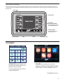
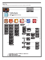
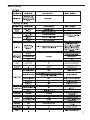
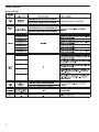
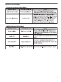
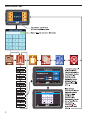
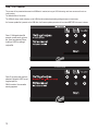
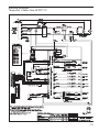
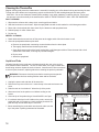
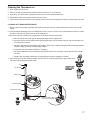
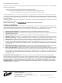
Wilbur Curtis Co., Inc.
Service Manual – G4 ThermoPro 1 Gallon Twin
Important Safeguards/Symbols
This equipment is designed for commercial use. Any servicing other than cleaning and routine maintenance
should be performed by an authorized Wilbur Curtis Company Service Technician.
• DO NOT immerse the unit in water or any other liquid
• To reduce the risk of fire or electric shock, DO NOT open service panels. There
are no user serviceable parts inside.
• Keep hands and other items away from hot areas of the unit during operation.
• Never clean with scouring powders or harsh chemicals.
Symbols:
WARNINGS – To help avoid personal injury
Important Notes/Cautions – from the factory
Model
G4TP1T
Sanitation Requirements
This Curtis Generation 4 Unit is Factory Pre-Set and Ready to Go Right from the Box.
Following are the Factory Settings for your G4 Coffee Brewing System:
• Brew Temperature = 200°F
• Water Bypass = LARGE & MEDIUM Brew Only
• Brew Volume = Set to Vessel Requirement.
CAUTION: Please use
this setup procedure
before attempting to use
this brewer. Failure to follow the
instructions can result in injury or the
voiding of the warranty.
IMPORTANT: Equipment
to be installed to comply
with applicable governmental plumbing/electrical codes
having jurisdiction.
CAUTION: DO NOT
connect this brewer to hot
water. The inlet valve is
not rated for hot water.
ISO 9001:2008 REGISTERED
WILBUR CURTIS CO., INC.
6913 West Acco Street
Montebello, CA 90640-5403
For the latest information go to
www.wilburcurtis.com
Tel: 800-421-6150
Fax: 323-837-2410
System Requirements:
• Water Source 20 – 90 PSI (Minimum Flow Rate of 1 GPM)
• Electrical: See attached schematic for standard model or visit www.wilburcurtis.
com for your model.
SETUP STEPS
1. The unit should be level (left to right - front to back), on a secure surface.
2. Connect the water line to the water inlet fitting on the rear of the unit. Water volume flow to the machine
should be consistent. Use tubing sized sufficiently to provide a minimum flow rate of one gallon per minute.
NOTE: A water filtration system must be used to help maintain trouble-free operation. Air must be
purged from the cartridge prior to connection to equipment. In areas with extremely hard water,
we highly recommend the use of a Curtis approved water filter. For our full line of filters, please log
on to www.wilburcurtis.com.
NSF International requires the following water connection:
1. A quick disconnect or additional coiled tubing (at least 2x the depth of the unit) is required so
that the unit can be moved for cleaning.
2. This unit must be installed with adequate backflow protection to comply with applicable federal,
state and local codes.
3. Water pipe connections and fixtures directly connected to a portable water supply shall be sized,
installed and maintained in accordance with federal, state, and local codes.
3. Connect the unit to electrical outlet with appropriate amperage rating (see serial tag on machine).
4. Once power has been supplied to the unit, flip the toggle switch to the ‘ON’ position (located on the rear of
the unit), the water tank will begin to fill. When the water level in the tank reaches the probe, the heating
element(s) will turn on.
5. Water in the heating tank will require approximately a half hour before reaching operating temperature
(factory setting of 200°F). Where applicable, turn on the Universal Control Module (UCM). When the unit
reaches operating temperature, it will display “READY TO BREW”.
For the latest specifications and information go to www.wilburcurtis.com
1
Your Curtis G4/Gold Cup Series is Factory Pre‑Set for Optimum Performance.
After connection to water and power; turn on the brewer at the rear toggle switch. You will hear a beep and the status lights will come on for a moment.
The screen will display
MODEL NUMBER
CONTROL BD NUMBER
When the proper level is reached
FILLING
. Next
HEATING
is displayed. Water will fill the tank (2-3 minutes depending on water flow rate).
will appear on the screen. It takes approximately 30 minutes to reach the set point temperature.
Control will display
READY TO BREW when temperature reaches the set point. The unit is now ready to brew.
COFFEE BREWING INSTRUCTIONS
1. Brewer should be ON. Confirm this at the toggle switch on the back of the brewer. The touch screen should read Ready to Brew.
2. Place an empty coffee container centered beneath the brew cone.
WARNING – AVOID SCALDING: USE BOTH HANDLES FOR BETTER CONTROL. The brew cone may be filled with hot coffee
grounds and is difficult to manage with one hand.
The coffee vessel is heavy when full. Take precautions to avoid dropping while moving.
3. Place a new paper filter into the brew
cone.
6. Start the brew cycle by hold your finger
on the desired brew icon. As soon as
you hear the click of the brew valve, the
brew cycle has started and you can lift
your finger.
Brew Code: You may find that when a brew
button is pressed, a key pad appears on the
screen. This is a brew lock-out feature that
2
4. Fill the brew cone with the proper
amount of ground coffee.
requires a code to be entered before a brew
will start. The default is OFF.
CAUTION: When enabled, as soon as you
enter the brew code a brew cycle starts.
Refer to page 8 for more information about the
Brew Code.
5. Transfer the filled brew cone to the
brewer.
During the brew cycle, an animated 1½
gallon server icon will appear on the screen
and a brew timer will count down the time
remaining on the brew cycle.
Touch Screen Control Module
The touch screen turns on when power is available to the controller. The screen will contain standard control feature such as symbols and buttons. Pressing these elements with your finger tip will activate the programming functions. The default screen, as well as some added control buttons are shown in the
illustration below.
STATUS LIGHTS
BREW BUTTONS
CURTIS LOGO
TO ENTER PROGRAMMING
Tap Curtis logo 5 times to bring
up the ACCESS CODE screen.
CONTROL SYMBOLS
All of these symbols may not
be visible at one time.
RETURN TO HOME
UNDO
SCROLL
RETURN TO PREVIOUS
PROGRAMMING
ACCESS CODE screen. Default is 1 2 3 4.
Once the code is entered, press OK. The
Main Menu screen will appear.
The access code can be reset in Control
Settings, PASSWORDS.
MAIN MENU screen contains six control icons:
RECIPES, CONTROL SETTINGS, BREW SETTINGS,
MODEL SELECT, SETTINGS SUMMARY and EXIT.
PROGRAMMING Continued . . .
3
Menu Tree
This chart explains how to enter the program mode and menu selections available from the MAIN MENU.
4
Menu Features
5
Menu Features
Brew Settings
6
System Fault Messages
7
Brew Access Code
8
USB – Easy Programming
There are two methods that can be used to change the default settings on G4 brewers. They can be programmed at the brewer by
the touch screen universal control module (UCM) or the settings can be changed using the USB (Universal Serial Bus) data port
on the side of the brewer. Using the USB connection and a flash memory data storage device will easily reprogram the settings
simply by copying data.
The flash drive can upload or download the entire setting from one G4 brewer, into another G4
brewer. This eliminates the need to walk through the usual steps in reprogramming that would
be required when you use the touch screen to make a change. This is an advantage for a
service technician when standardizing the program settings on multiple G4 brewers.
Use a USB drive with USB 2.0 support and a type-A USB connection. Storage capacity should
be 2 GB minimum (reference the illustration on page 2).
IMPORTANT: The flash drive must be completely blank. Before starting, please erase any files that may be in the USB drive.
SOFTWARE INFORMATION TRANSFER
UPLOAD TO USB
1. Make sure the brewer is on. Determine that the G4 brewer you wish to copy is properly programmed for your desired settings.
2. Connect an empty flash drive into the USB port on the brewer. The UCM on the brewer will upload all of the particular setup
data onto the flash drive. The yellow LED on top of the touch screen will light indicating that data is transferring. This will only
take a second to complete.
DOWNLOAD TO BREWER
1. Select the brewer you wish to make the program changes on. The brewer should be on.
2. Plug the loaded flash drive into the USB port on the brewer. The data copied from the first G4 brewer will automatically download, overwriting all the settings that were on the second brewer.
3. The red LED on the UCM will indicate that the download is in process. This will only take a second.
4. Once the download is complete, the UCM will reboot in order for the changes to take effect.
5. Remove the flash drive. The download is complete. The data on the flash drive can be downloaded into as many G4 brewers
as needed.
9
USB – File Transfer
This screen will be presented whenever the USB flash is inserted, as long as UCM is showing main brew screen and is not currently brewing.
The default action is ‘No action’.
The UCM will always create a backup on the USB flash drive before downloading settings/recipes or screen saver.
If a firmware update file is present on the USB flash, the firmware update procedure will be started BEFORE this screen is shown.
Case 1: Settings/recipes file
present, screen saver not present. User has selected ‘Download from USB’ for settings/
recipes file.
Case 2: As above, but user has
selected ‘Upload to USB’ for settings/recipes file.
With this action, the overwrite
warning appears.
10
Illustrated Parts
Main View
1
2
11
3
12
13
4
14
5
6
7
8
9
10
ITEM NO.
1
2
2A
3
3A
4
5
6
7
8
9
10
11
12
12A
13
14
14A
PART NO.
WC-5459
WC-37121*
WC-853
WC-844-101*
WC-844-102
WC-3417
WC-1825
WC-14045-101*
WC-8559
WC-3503 *
WC-3518 *
WC-58037-102
WC-5983-101
WC-847 *
WC-883
WC-1501
WC-102 *
WC-103
DESCRIPTION
COVER, TOP WRAP
KIT, DUMP VALVE LEFT
VALVE, BREW DUMP LEFT 240V 12W (EXPORT UNITS ONLY)
VALVE, BYPASS 120V-14W NON ADJUSTABLE w/RESTRICTOR (WC-2945)
VALVE, BY-PASS, 220V NON-ADJUST W/RSTRCTR (EXPORT UNITS ONLY)
BREW CONE,ASSY W/SPLASH POCKET BRWN STYLIZED HOT COFFEE
FAUCET ASSY, HOT WATER
CURRENT SENSOR ASSY G4
RELAY, SOLID STATE 40A w/INTEGRATED HEAT SINK
LEG, 3/8”-16 STUD SCREW BUMPBER
LEG, GLIDE 3/8”-16 STUD SCREW
COVER, CENTER WRAP
PANEL, TOP WRAP BACK
VALVE, INLET 2GPM 120V-10W
VALVE, INLET 2 GPM 240V 10W (EXPORT UNITS ONLY)
FUSE, HOLDER ASSY w/5A FUSE
SWITCH, TOGGLE NON-LIT SPST 15A 125/250VAC RESISTIVE
SWITCH, TOGGLE DPST 25A 125/250VAC (EXPORT UNITS ONLY)
* RECOMMENDED PARTS TO STOCK
11
Illustrated Parts
Top Wrap
15
16
40
17
18
19
20
21
24
22
23
12
ITEM NO.
15
16
17
17A
18
18A
19
19A
20
20A
21
22
23
24
PART NO.
WC-2977-101K*
WC-43089*
WC-442 *
WC-446
WC-37122*
WC-854
WC-589-101
WC-589-102
WC-13450
WC-13450-101
WC-10000
WC-4212-02*
WC-29050*
WC-10008
DESCRIPTION
KIT, SPRAYHEAD FITTING PLASTIC
GASKET, 1.00”OD x .625” I.D. x .030” THK RED SILICONE 40 SHORE
SOLENOID, LOCK BREW CONE RIGHT 120VAC
SOLENOID, LOCK BREW CONE RIGHT 220V (EXPORT UNITS ONLY)
KIT, DUMP VALVE RIGHT
VALVE, BREW DUMP RIGHT 240V 12W (EXPORT UNITS ONLY)
TRANSFORMER, 120VAC-24VAC 4.8VA W/TERMINALS
TRANSFORMER,240VAC- 24V 4.8VA W/CONNECTOR (EXPORT UNITS ONLY)
HARNESS ASSY, COMPLETE G4TP2T/G4GEMT/G4GEMTIF
HARNESS ASSY COMPLETE (EXPORT UNITS ONLY)
CONTROL MODULE, TOUCH SCREEN G4
NUT, 5/8-18 JAM PLASTIC-ULTEM
SPRAYHEAD ASSY, AFS-AMBER
UNIVERSAL HOST ADAPTER (USB)
* RECOMMENDED PARTS TO STOCK
Illustrated Parts
Heating Tank
25
26
28
27
29
30
31
32
33
34
35
36
ITEM NO.
25
26
27
28
29
30
31
32
33
34
35
36
PART NO.
WC-37008*
WC-43067*
WC-37266*
WC-5527K*
WC-37317*
WC-37357*
WC-62033 WC-934-04*
WC-1438-101*
WC-522 *
WC-4382*
WC-43055*
DESCRIPTION
KIT, TANK LID ROUND
O-RING, 4-1/2 I.D. x Ø.285 C.S. SILICONE
KIT, FITTING TANK OVERFLOW (8MM)
KIT, PROBE WATER LEVEL O-RING & NUT
KIT, STRAIGHT FITTING & BUSHNG (8MM)
KIT, STRAIGHT PLASTIC FITTING KIT, STRAIGHT PLASTIC FITTING
TANK, COMPLETE GEMTS W/ULTEM FITTINGS
KIT,ELEMENT HEATING 2.5KW 220V W/ JAM NUT & SILICONE WASHERS
SENSOR, TEMPERATURE TANK
THERMOSTAT, HI LIMIT HEATER DPST 277V-40A
GUARD, SHOCK (HEATING ELEMENT
GUARD, SHOCK RESET THERMOSTAT
* RECOMMENDED PARTS TO STOCK
13
Illustrated Parts
37
38
39
ITEM NO.
37
38
39
40
40A
41
PART NO.
GEM-6 *
WC-5310*
WC-5350*
WC-10001*
WC-10015
WC-596
DESCRIPTION
FILTER, 500PK GEM-12/230A
TUBE, 5/16 ID x 1/8W SILICONE (SOLD PER FOOT)
TUBE, SILICONE Ø1/2” ID x Ø3/4” OD x 1/8” WALL (SOLD PER FOOT)
UNIVERSAL POWER MODULE – G4 120V
UNIVERSAL POWER MODULE – G4 220V (EXPORT UNITS ONLY)
FILTER, NOISE EMI 250VAC/30A (EXPORT UNITS ONLY) NOT SHOWN
* RECOMMENDED PARTS TO STOCK
Rough-In Drawing
14
Electrical Schematic
ThermoPro 1 Gallon Twin G4TP1T-10
15
Cleaning the ThermoPro
Regular cleaning and preventive maintenance is essential in keeping your coffee brewer looking and working like new.
To clean the coffee brewer and components, prepare a mild solution of dish washing detergent and warm water.
CAUTION – Do not use cleansers, bleach liquids, powders or any other substance containing chlorine. These products promote corrosion and will pit the stainless steel. USE OF THESE PRODUCTS WILL VOID THE WARRANTY.
DAILY CLEANING
1. Wipe exterior surfaces with a damp cloth, removing spills and debris.
2. Slide the brewcone out and clean it. Wipe the sprayhead area with a cloth soaked in a mild detergent solution.
3. Rinse with a cloth soaked with clean water. Dry the brewcone and sprayhead area.
4. Drain drip trays of coffee. Water rinse.
5. Dry the tray.
WEEKLY CLEANING
1. Reach behind the brewer and turn off the power at the toggle switch. Allow the brewer to cool.
2. Clean the sprayhead and dome plate area.
a.Remove the sprayhead, unscrewing counterclockwise from the dome plate.
b.Thoroughly clean and rinse the dome plate area.
c. Clean the brewcone rails with a brush soaked with a mild detergent solution. Rinse the area with a cloth
soaked with clean water, removing any residual detergent.
d.Dry the area.
c. Attach the sprayhead.
Liquid Level Probe
Cleaning intervals for the probe are to be determined by the user or the service
tech, based on water conditions. The use of water filters, or the type of water filter
that is being used can impact the service interval. Intervals can be from one month
to several years, however, replacing rather than cleaning the probe is preferable.
WARNING: Disconnect electrical power before removing access panels!
This procedure involves working with hot water and hot surfaces!
1. Unplug the power cord and shut off the water line.
2. Remove the top cover of the unit. Locate the top of the tank and remove the
cover.
3. Drain the tank to a level about 3” below the tip of the probe.
4. Allow some time for the probe to cool before working on the
brewer.
5. Clean the tip of the probe using a Scotch-BriteTM scuff pad.
6. If a residual white layer is still visible on the probe, remove the
probe and soak it in vinegar or a scale removing chemical. Repeat this step until the white layer is removed.
7. When assembling the probe back onto the tank, make sure the
tip of the probe is pointing downward as illustrated.
16
HEATING TANK
LIQUID LEVEL PROBE
Cleaning the Thermoserver
1. Drain coffee from the server.
2. Fill the liner with a mild detergent solution and let it stand for 10 to 15 minutes.
3. After about 15 minutes take a sponge brush and scrub out the stainless steel liner.
4. When clean, drain out the soapy solution from the server.
5. Fill the server with clean water to rinse detergent from inside the unit. Repeat this rinsing until the water runs clear.
CLEANING OF THERMOSERVER FAUCET
1. Remove the faucet handle assembly. Take hold of the bonnet and turn counterclockwise to unscrew it from the
faucet.
2. Clean the handle assembly with a mild detergent solution. Once it is clean, rinse it off with water. Inspect for cracks
or tears in the seat cup. Replace the seat cup if damaged.
3. With servers having a coffee level gauge glass, follow these cleaning instructions.
a.Remove the top cap of the gauge glass guard and pull out the glass tube.
b.Carefully remove the two washers that seal the glass tube. One is located in the top cap and the other is in
the bottom faucet shank.
c. Using the narrow brush provided for this purpose, brush out the inside of the glass with a detergent solution.
Rinse the sight glass tube of all detergent residue.
d.Clean and rinse the washers. Replace if necessary.
e.Pay special attention to the small gauge glass liquid level hole on the shank. Use a narrow brush to clean
this hole.
f. Replace the sight glass. Make sure the top and bottom silicone washers are seated.
4. After cleaning, return the handle assembly onto the faucet. Carefully assemble the parts. Make sure
the faucet and gauge glass properly seal.
CAP
TOP WASHER
GAUGE GLASS
BOTTOM WASHER
GAUGE GLASS GUARD
BRUSH OUT HOLE AT BASE
OF GAUGE GLASS/SHANK
17
Product Warranty Information
The Wilbur Curtis Co., Inc. certifies that its products are free from defects in material and workmanship under normal use. The following limited
warranties and conditions apply:
3 Years, Parts and Labor, from Original Date of Purchase on digital control boards.
2 Years, Parts, from Original Date of Purchase on all other electrical components, fittings and tubing.
1 Year, Labor, from Original Date of Purchase on all electrical components, fittings and tubing.
Additionally, the Wilbur Curtis Co., Inc. warrants its Grinding Burrs for Forty (40) months from date of purchase or 40,000 pounds of coffee, whichever comes first. Stainless Steel components are warranted for two (2) years from date of purchase against leaking or pitting and replacement
parts are warranted for ninety (90) days from date of purchase or for the remainder of the limited warranty period of the equipment in which the
component is installed.
All in-warranty service calls must have prior authorization. For Authorization, call the Technical Support Department at 1-800-995-0417. Effective
date of this policy is April 1, 2003.
Additional conditions may apply. Go to www.wilburcurtis.com to view the full product warranty information.
CONDITIONS & EXCEPTIONS
The warranty covers original equipment at time of purchase only. The Wilbur Curtis Co., Inc., assumes no responsibility for substitute replacement parts installed on Curtis equipment that have not been purchased from Wilbur Curtis Co., Inc. The Wilbur Curtis Co., Inc. will not accept any
responsibility if the following conditions are not met. The warranty does not cover and is void under the following circumstances:
1) Improper operation of equipment: The equipment must be used for its designed and intended purpose and function.
2) Improper installation of equipment: This equipment must be installed by a professional technician and must comply with all local electrical,
mechanical and plumbing codes.
3) Improper voltage: Equipment must be installed at the voltage stated on the serial plate supplied with this equipment.
4) Improper water supply: This includes, but is not limited to, excessive or low water pressure, and inadequate or fluctuating water flow rate.
5) Adjustments and cleaning: The resetting of safety thermostats and circuit breakers, programming and temperature adjustments are the
responsibility of the equipment owner. The owner is responsible for proper cleaning and regular maintenance of this equipment.
6) Damaged in transit: Equipment damaged in transit is the responsibility of the freight company and a claim should be made with the carrier.
7) Abuse or neglect (including failure to periodically clean or remove lime accumulations): Manufacturer is not responsible for variation
in equipment operation due to excessive lime or local water conditions. The equipment must be maintained according to the manufacturer’s
recommendations.
8) Replacement of items subject to normal use and wear: This shall include, but is not limited to, light bulbs, shear disks, “0” rings, gaskets,
silicone tube, canister assemblies, whipper chambers and plates, mixing bowls, agitation assemblies and whipper propellers.
9) Repairs and/or Replacements are subject to our decision that the workmanship or parts were faulty and the defects showed up under normal
use. All labor shall be performed during regular working hours. Overtime charges are the responsibility of the owner. Charges incurred by
delays, waiting time, or operating restrictions that hinder the service technician’s ability to perform service is the responsibility of the owner
of the equipment. This includes institutional and correctional facilities. The Wilbur Curtis Co., Inc. will allow up to 100 miles, round trip, per
in-warranty service call.
RETURN MERCHANDISE AUTHORIZATION: All claims under this warranty must be submitted to the Wilbur Curtis Company Technical
Support Department prior to performing any repair work or return of this equipment to the factory. All returned equipment must be repackaged
properly in the original carton. No units will be accepted if they are damaged in transit due to improper packaging. NO UNITS OR PARTS WILL
BE ACCEPTED WITHOUT A RETURN MERCHANDISE AUTHORIZATION (RMA). RMA NUMBER MUST BE MARKED ON THE CARTON
OR SHIPPING LABEL. All in-warranty service calls must be performed by an authorized service agent. Call the Wilbur Curtis Technical Support Department to find an agent near you.
ECN 16523 . 4/23/15 . rev B . v2
12/24/14 . ECN 16326 . rev A
WILBUR CURTIS CO., INC.
10/16/13 . EDR 8920 . rev NC
6913 Acco St., Montebello, CA 90640-5403 USA
Phone: 800/421-6150 Fax: 323-837-2410
Technical Support Phone: 800/995-0417 (M-F 5:30A - 4:00P PST)
Web Site: www.wilburcurtis.com
E-Mail: [email protected]
5/2015 . F-3964 rev B