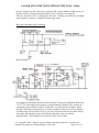
1
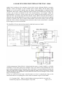
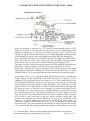
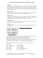
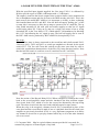
A LOOK INTO THE CIRCUITRY OF THE TEAC A3440
THE TEAC A3440
By
Les Carpenter G4CNH
DISCLAIMER
This document has been composed purely by trying to analyse the original Teac
A3440 circuit diagrams. No physical electrical measurements have been made to
support the theories of operation and the author accepts no responsibility for any
errors resulting from his analysis of the Teac circuits. The author welcomes any
feedback that may go towards the making of a more accurate document. It is hoped
however that the document, offered in good faith, will serve to enable readers to
understand more the operation of their Teac machines.
REVIEWED December 2015
© L.Carpenter 2009 May be copied without consent provided it is not used for
commercial purposes or financial gain of any kind.
Page 1 of 31
A LOOK INTO THE CIRCUITRY OF THE TEAC A3440
In our understanding of how all of the Teac circuits work together, I am attempting to
unravel the power supply first. Remember that any power supplies or indeed logic
board commands, that interact with the signal circuits, do so on a four times basis. I
will only describe those actions on channel 1 as per the official circuit diagrams, just
bear in mind that duplicate circuits will also be operating on channels 2, 3 and 4. The
text is best read in conjunction with the re-drawn circuits on pages 21 and 22.
Let’s run through the fuses as depicted on page 23.
Fuse 903 (1 Amp anti-surge): This feeds diode D601 and with C601, establishes a
7V rail to supply the VU Lamps. This 7V is also fed via D612 to potential divider
R620/R621 to provide a 3.5V supply to a circuit on the signal board called POWER
MUTE (E) which really means Q110 Emitter. 7V is also fed via R619 to charge C609
which gives a time constant of 4.7 seconds; the rail is called POWER MUTE (B) or
more correctly Q110 Base. Q110 cut off time is reached in approximately 3.7 seconds
but until then, Q110 is turned on and forward biases Q109. This transistor forms a
muting circuit and places a low impedance across the audio line feeding the
headphone amplifier and audio output RCA socket.. Thus any audio pops and noises
are muted until all the rails and other circuits are up and running. After the time delay,
Q110 turns off and this also turns off Q109 to enable audio output. D613 serves to
discharge C609 quickly on power down so that the delay circuit is ready for the next
power up, particularly when the power has been accidentally turned off and back on
again quickly. It should be noted that if the wrong types of VU lamps are fitted, they
may draw too much current and this may affect the muting circuit causing no audio
output on ALL channels. Q110 and its cousins on the other channels are good
transistors to check first if loss of output is experienced on any single channel.
Fuse 904 (2.5 Amp anti-surge): This feeds Bridge rectifier made up by D602,
D603, D604 and D605. The output is smoothed by C602 and is fed to three 24V
regulator circuits, two are on the Power supply board (Q602 and Q604) and the third
is on the control board (Q732). The three regulators have slow rise outputs and will
establish their supplies within one second, the control board first (Q732) followed by
Q604 and then Q602.
A quick look however at the Q602 regulator will reveal that they all have similar
circuitry.
R602 and C603 provide the slow rise of the output voltage as previously mentioned.
Q601 and Q602 form a Darlington pair with Q603 acting as a basic comparator. This
transistor will switch on when its Base voltage is approximately 0.6V more than the
6.2V Zener diode (D610) placed in its Emitter circuit. Due to the potential divider
R605/R606, this will occur when the output voltage reaches 24V. Q603 turning on
diverts base current away from Q601 causing the circuit to stabilise at 24V.
We will discuss each regulator in turn, starting with Q732.
© L.Carpenter 2009 May be copied without consent provided it is not used for
commercial purposes or financial gain of any kind.
Page 2 of 31
A LOOK INTO THE CIRCUITRY OF THE TEAC A3440
Q732 Regulator: As well as providing 24V for the control Flip Flop circuits, the
supply is also fed back to the power board as required to control relays residing there.
As described later, it is also used to switch other external circuits but first we will be
dealing with the machine having just been switched on where it should be in STOP
mode. This mode is enforced by Q712 which receives a pulse via C709 on power up.
This transistor applies a short reset command pulse to all Flip Flops as follows.
Via D704 to reset the PLAY Flip Flop,
Via D708 to reset the FAST FORWARD Flip Flop,
Via D712 to reset the REWIND Flip Flop and,
Via D715 to reset the RECORD Flip Flop.
The action of these Flip Flops will be described later.
Note that the local and remote STOP switches are also wired to this STOP line so
operating these switches will have the same effect as Q712 and reset all Flip Flops via
the diodes listed above..
Finally, the STOP line is also fed out to a micro switch S901 which Teac call a safety
switch. It is operated by the cam associated with the right hand tape lever arm such
that when the tape runs out and the arm drops, then a permanent STOP command is
imposed on the STOP line, until the arm is lifted when the tape is re-laced.
Finally, the 24V from the Q732 regulator is fed out to the local and remote switches
to provide a supply for the light emitting diodes used to indicate Pause and Record
when required.
Q604 Regulator: This supplies 24V to the capstan servo board but not the motor
itself, just the electronic control circuit. It also supplies 24V to the signal circuits and
is defined on the TEAC circuit as RELAY +B, providing power for the RECORD and
FUNCTION relays fitted to each of the four channels.
Q602 Regulator: This supplies 24V to the STOP SENSOR board and also to the
signal circuit amplifiers according to the original circuit annotations. Actually it does
a bit more than this, powering both the record and play amplifiers, meter amplifiers
and the Tape EQ selection circuit.
Fuse 901 (2.5 Amp anti-surge): This supply is bridge rectified by diodes D606,
D607, D608 and D609. The resultant un-regulated DC supply is used to supply the
Servo Motor via another safety switch mechanically ganged with the one previously
described in the section dealing with Q732. The switch is S902 operated by the same
cam on the right hand take up lever. When the tape runs out, the switch opens and
removes power from the servo motor and is the reason for no capstan motion until the
arm is lifted when the tape is re-laced. These two safety switches have been found
broken on non working machines and are worth a good visual check when looking for
faults.
© L.Carpenter 2009 May be copied without consent provided it is not used for
commercial purposes or financial gain of any kind.
Page 3 of 31
A LOOK INTO THE CIRCUITRY OF THE TEAC A3440
The supply is also tasked with the job of powering up the Brake and Capstan
solenoids but done in a rather mysterious way for the unwary. It must be remembered
that the two sets of solenoids work in opposite ways, the capstan solenoid has to be
energised to engage the pinch roller but the brake solenoids have to be energised to
disengage the brakes. Note that the Left and Right hand brake solenoids are wired in
series and both energise at the same time. Now the mysterious bit!
First however, a reminder that a solenoid requires more power to engage it than that
required to keep it engaged and so there are two supply paths made available for the
solenoids. A simplified brake solenoid circuit appears on Page 24.
Fuse 902 (2.5 Amp anti-surge) provides one of the supply paths; fed via D614 it is
un-switched, available all the time and is used as the holding supply. For the full
power engage voltage, this honour is given to Q606, driven by Q607, which gets a
pulse from Q722 via C714 on the control board when required. This pulse engages the
pinch wheel and takes off the brakes, after which the current from D614 is sufficient
to maintain the solenoids in their held positions. As we shall see later, this is not the
end of the Brake/Capstan story as elements exist on the control board for switching
the return current paths of the solenoids.
Fuse 905, Fuse 906 and Fuse 907 (All 1 Amp anti-surge) provide protection for the
reel motors and I must confess that reverse engineering of this circuit was a real pain.
Some of the description that follows is still based on a little guesswork but if anyone
can come up with a better description, please correct me!
For example, the motor circuit makes use of a diode switch, consider the following.
With the centre line open circuit, the AC voltage of whatever polarity cannot pass
through from input to output as it always meets a reverse biased diode. If however the
open circuit centre line is replaced with a short circuit then the AC input can reach the
output. A positive cycle will pass through D617, the short circuit and then through
D616. A negative cycle will pass through D618, the short circuit and then through
D615. By substituting an active switch in place of the centre line then the AC voltage
can be switched to the motor. This circuit operation is not readily apparent looking at
the Teac circuit but if you re-draw then the true story becomes revealed.
I have redrawn the circuit, removing the Large/Small Spool switches to make things a
little clearer.
First the Large Spool circuit as depicted in the Teac circuit.
I shall place the circuit on the next page so that the description is closer to it.
© L.Carpenter 2009 May be copied without consent provided it is not used for
commercial purposes or financial gain of any kind.
Page 4 of 31
A LOOK INTO THE CIRCUITRY OF THE TEAC A3440
This is the Beast! The easy bit is Fast Forward and Rewind, these functions are performed
by the Relays K602 (Fast Forward) and K603 (Rewind). They reside on the power board
but are controlled by driving circuits on the logic control board that ensures that only one
relay can be energised at any one time. When they are activated, they place what I have
labelled as High Speed Supply, directly to the required motor. Note that some of the voltage
applied is leaked via 600 Ohm resistor R904 such that whilst driving the selected motor
fast, the resistor provides back tension to the other motor. It is the Play circuit that has
provided the biggest challenge to unravel. As previously mentioned, Diodes D615, D616,
D617 and D618 appear to form a diode switch not to dissimilar to a bridge circuit but the
diodes are connected such that they make the impedance high between input and output.
Note that there are no filter components on the output to create DC which would upset the
AC Motors.
A supply is made available via D619 and D620 to charge up C612 while the machine is set
at Stop. This turns on the transistors and lowers the impedance between each side of the
diode circuit which effectively shunts the Reel Relay K604 so that it cannot energise. While
K604 and the Play Relay K601 are de-energised then the Reel Motors cannot run. When
Play is selected, a signal from the logic board energises K601 which does two jobs. First it
connects the Reel motors to the diode switch output. Because this is presently at low
impedance it provides larger than normal voltages to kick start the motors from their
stationary position. At the same time, another contact set of the Play Relay releases the
© L.Carpenter 2009 May be copied without consent provided it is not used for
commercial purposes or financial gain of any kind.
Page 5 of 31
A LOOK INTO THE CIRCUITRY OF THE TEAC A3440
supply that is turning on the transistors in the diode circuit, allowing K604 to energise,
placing a motor run supply via the variable power resistor R902. So the diode circuit
appears to be only used to initially start the motors. Note that R902 is labelled BACK
TENSION when really I think it should be called TAKE UP TENSION but I left this error
in place, just as they are labelled in the Teac documentation, even though I think the
documentation is incorrect. In this respect, the service manual for the machine gets you to
adjust the take up tension using the back tension resistor R903! Note that this resistor is
doing the same job that R904 does in rewind, it’s just that a lot more back tension is applied
in Play to provide good Tape to Head contact. R904 is the fixed resistor on the far right
hand side of the resistor mounting bracket whilst the other fixed resistor R901 is mounted
by the supply reel on its own bracket.
The Small Reel Circuit after the front panel switch has been set to Small.
In this arrangement, Relay K604 is isolated and the source of motor supply is via R902
with R901 in series thus giving less available torque. The diode circuit performs the same
task of kick starting the motors when the Play relay K601 is operated and then bowing out
after C612 has lost its charge. Note however that the diode circuit is fed from a lower
voltage tapping on the transformer so the initial kick start is not as strong as it was for the
large reel switch position.
So now we will look at the logic control board to see how it controls the relays so far
mentioned and how everything inter-reacts. But first another couple of stiff drinks!
© L.Carpenter 2009 May be copied without consent provided it is not used for
commercial purposes or financial gain of any kind.
Page 6 of 31
A LOOK INTO THE CIRCUITRY OF THE TEAC A3440
Logic Control Board:
The best starting point is to examine the machine after switch on, when all of the bi-stable
Flip Flops have been reset by the short Low going pulse on the STOP Line produced, as
previously mentioned, by Q712. Let us take a look at one of the Flip Flop circuits, they are
all basically the same and we will take the PLAY Flip Flop as an example.
When the STOP line goes low, D704 causes Q702 to turn off resulting in its collector going
High. This High is fed back to Q701 via R702 and R701 and consequently turns Q701 on.
Its collector goes Low and due to D719, it ensures that Q702 remains off after the stop
pulse has ended. When a Play command is given from either the Local or Remote
momentary Play button, D701 grounds the supply coming from R702 and consequently
Q701 now turns off. The resulting High on Q701 collector turns on Q702 and subsequently,
its collector falls. This Low is coupled via D718 to keep Q701 off after the Play button has
been released. The Flip Flop will remain in this state until a Low going pulse is applied
either by the Fast Forward button (via D702), the Rewind button (via D703) or a Stop
command on the Stop line via D704.
The thing to remember is that when SET the Flip Flop output is LOW and when
RESET, the Flip Flop output is HIGH.
It follows then that after switch on all Flip Flop outputs should be High and with this in
mind we can investigate the effects of this on the other circuit elements.
On the following page we start with a simplified block diagram of the Motor and Solenoid
control circuits, adopted from the original Teac Service Manual but with extra information
to assist in grasping the workings of these circuits.
© L.Carpenter 2009 May be copied without consent provided it is not used for
commercial purposes or financial gain of any kind.
Page 7 of 31
A LOOK INTO THE CIRCUITRY OF THE TEAC A3440
After switch on:Play Flip Flop – will be holding Q719 Off so the Play relay K601 is de-energised. It also
holds Q721 Off so the Capstan solenoid is de-energised. (Pinch roller disengaged)
These two circuits have an over ride signal derived from the Stop Sensor board that can
turn both transistors Off, which we will discuss later.
Fast Forward Flip Flop - will be holding Q724 Off so the Fast Forward relay K602 is
de-energised.
Rewind Flip Flop - will be holding Q725 Off so the Fast Rewind relay K603 is deenergised.
Brakes: All three of the above Flip Flops are OR’d together by diodes D732, D733 and
D734 which control Q722 and Q723. This means that the Brakes are OFF when any of the
three above Flip Flops are SET.
A simplified brake solenoid circuit has been added and appears on Page 24.
Record Flip Flop – not shown in the above block diagram, it has a few twists and turns
which will be discussed later. Needless to say, from switch on it will be holding Q726 Off
so the signal board is not getting a Record command signal and the Record LED is disabled
due to Q728 being disabled. This will also prevent Q727 operating the Pause LED.
OK, let’s select Play and see what happens.
© L.Carpenter 2009 May be copied without consent provided it is not used for
commercial purposes or financial gain of any kind.
Page 8 of 31
A LOOK INTO THE CIRCUITRY OF THE TEAC A3440
Play:
The PLAY SET line goes Low and via D701 sets the Play Flip Flop so its output is Low. It
has also sent a cursory reset pulse to the FF Flip Flop via D706 and to the REW Flip Flop
via D711.
Note also that while the Play button is pressed and only when it is actually pressed, then
Q709 is turned on and invites an input from the Record button, if so wished. However we
will stay with Play for the meantime but I felt it important to highlight now how Q709 and
Q710 control the selection of Record. It highlights why Record can only be selected using
both Record and Play buttons.
With the Play Flip Flop now Low, Q719 and Q721 are turned on, resulting in the capstan
solenoid engaging the pinch wheel and relay K601 energised to start the motors.
A Low is fed via D732 to turn on transistors Q722 and Q723 which have the effect of
releasing the brakes. The action of Q722 turning on Q723 also sends a pulse via C714 to
Q607 on the power supply board to drive Q606 to provide a short high pull in current as
described under the section dealing with. Fuse 902.
So it should be remembered that the brakes are controlled by either +24V supply or ground
return using Q606 and Q723 respectively.
The machine should now be in Play mode and this brings into focus two other circuit
boards than can be dealt with here.
First off is the STOP SENSOR board.
This did absolutely nothing while the machine was stopped except that C804 had charged
up because Q804 was turned off. Subsequently Q805 (after a short delay) will be providing
a Low to a circuit on the logic board which we will deal with later and which I call the Stop
Interlock circuit. All we need to know at present is that the effect of Q805 being turned on
has not affected our ability to select Play. Now that the machine is running there will be
pulses produced by a magnet on the supply reel motor. The rotating magnet produces pulses
from the Hall Effect sensor, amplified by Q801, Q802 and Q803 to turn on Q804. This
transistor will starve supply to C804 which will rapidly discharge via R809 and Q804.Q805
will turn off but it has no effect on the Play logic circuits for as we shall see shortly, it only
affects Play logic control when the machine is in Fast Forward or Rewind modes.
© L.Carpenter 2009 May be copied without consent provided it is not used for
commercial purposes or financial gain of any kind.
Page 9 of 31
A LOOK INTO THE CIRCUITRY OF THE TEAC A3440
Stop Interlock Circuit
When the machine is powered up, C711 passes a short duration pulse to Q715
which in turn places a short duration Low to the base of Q716 which being a PNP
transistor is forced on. Its collector goes High and turns on Q717 which in turn
switches on Q718. This transistor places an over riding logic High onto the junction
of R744 and R745 which is presently High from the Play Flip Flop being Reset.
Note: Selecting Play at this time would SET the Play Flip Flop but its affect will be
held back by the over ride. After a short time interval, Q805 on the Stop Sensor
board will go Low, forcing Q717 off and consequently Q716 and Q718 off.
The logic over ride is removed from the junction of R744 and R745 and readies the
Play Relay, Capstan and Brake solenoids for operation when Play is selected.
When Play is selected, the supply reel rotates and this makes the Stop sensor board
signal go open circuit thus releasing Q717 which tries to turn on but there is no bias
available from Q716. So once again the circuit has had no effect on the Play mode.
At least that is how I see it, though it would appear that the circuit is fraught with
danger. Surely a leaky component would cause the circuit to latch up or if for
example Q715 was turned on by a noise spike via C711. This would cause Q716 to
turn on which would in turn provide the necessary bias to turn on Q717 as the input
from the Stop sensor board would be high impedance. This would turn on Q718
which would force the Play Relay to off, the Capstan pinch roller to disengage and
the brakes to come on. Then due to reel stoppage, the sensor board signal, after a
brief second or two while C804 charges via R808 and R809, would go Low forcing
the stop interlock to let go. The machine would start off in Play again as its Flip
Flop was still Set. This same problem has been seen on a number of these machines
but it seems to only occur once in any one session, by that I mean once after
powering the machine up and not influenced by any of the subsequent mode
settings. It is totally random and may not be observed for many power ups
afterwards; usually showing itself just after you set the machine to record some
important work! The cause remains elusive though one owner reported that a leaky
C711 caused a non functioning machine that would not allow Play to be selected.
© L.Carpenter 2009 May be copied without consent provided it is not used for
commercial purposes or financial gain of any kind.
Page 10 of 31
A LOOK INTO THE CIRCUITRY OF THE TEAC A3440
The designers appear to have placed their faith on C710 and C713 for noise
suppression.
The circuit really comes into its own when you have one of the fast modes (Fast
Forward or Rewind) in operation. If an attempt is made to engage Play whilst these
are selected then the Play Flip Flop will indeed be Set and at the same time the
action will Reset the Flip Flop of whichever fast mode is in operation. The reset
from whichever of these two Flip Flops (either from diode D726 or D727), will
force an output from Q718 which will prevent the Set Play Flip Flop from operating
the Play Relay and Capstan solenoid. However, drive to the motors will be removed
and the brakes applied. When the reels stop, the Stop Sensor board will detect this
non movement and allow the machine to automatically enter Play mode. This will
happen when Q718 on the Stop Interlock board is turned off by Q805 on the Stop
Sensor board.
I would never have believed that such a simple circuit would require such an
exhaustive description.
The second circuit to examine is the Capstan Servo board.
The motor is of the Servo type which means that although it performs the task as a
motor to drive the capstan, it also contains an additional winding whose output
frequency is proportional to the motor speed.
The output of the generator is fed to a low pass AC amplifier U1-1 which switches
Q1. The collector voltage of Q1 will be dependent on the settings of either VR1
(Low Speed) or VR2 (High Speed) and the speed at which Q1 is switched by U1-1.
U1-2 functions as a comparator, comparing the voltage on Q1 collector at its –
(inverting input) with that derived from the Pitch Control R905 at its + (non
inverting input). R905 is a centre tapped variable resistor such that when the Pitch
control is set to Off, it provides a fixed resistance of 2.5k Ohms and sets the + (non
inverting input) at approximately 18V. Let’s assume the motor speed is too slow,
this will switch Q1 slowly and subsequently its collector voltage will be higher than
18V. The comparator output will go Low and turn on Q2. This forward biases the
Darlington pair Q3 and Q4 which passes more current through the motors main
winding. As the speed increases, the voltage on Q1 collector will fall until it reaches
18V whereupon the comparator will switch to reduce motor current. Eventually the
motor speed will be held constant unless any of the inputs from VR1, VR2 or Pitch
© L.Carpenter 2009 May be copied without consent provided it is not used for
commercial purposes or financial gain of any kind.
Page 11 of 31
A LOOK INTO THE CIRCUITRY OF THE TEAC A3440
control change or loading of the capstan motor takes place. The Pitch control when
set to variable gives a voltage range to the comparator of 17 to 19 Volts.
If STOP is pressed or the tape runs out causing the right hand tension lever to fall,
then the logic circuits will be set as described at the beginning of the logic board
description.
Fast Forward and Rewind:
If one of the Fast Forward or Rewind modes is pressed during Play, then this will
cause the Play Flip Flop to Reset. This will release the pinch roller and attempt to
turn on the brakes by taking the cathode of D728 High. However, the Fast Forward
or Rewind Flip Flops will take over the task of keeping the brakes off by applying a
Low to the cathode of D733 or D734. In this way the machine can go safely into
these fast modes without damage to the tape.
The same diodes of course release the brakes when the Fast Forward or Rewind
modes are selected as normal i.e. from when the machine is at Stop. In addition,
each of these modes operates its own relay on the Power Board as mentioned earlier
using drivers Q724 in Fast Forward mode and Q725 in Rewind mode.
The only other modes to be covered are Record and Pause, these being sufficiently
interlocked to create more brain pain in unravelling their operation.
Record:
The Record Flip Flop has no influence over the operation of the machine so far
described. It does not operate any relays to start motors or operate the brakes or
capstan. All it does is operate relays on the signal circuits and to bring on bias
oscillators etc., however it does have some brain numbing interlock circuitry.
In order to Set the Record Flip Flop, two conditions must be in place.
1) A logic Low is required on the cathode of D742 but this is not taken directly to
the Record switch. It is connected to the collector of Q710 which has its emitter
connected to the Record switch instead. So for the Record switch to have any
effect, Q710 must be turned on by Q709 and this can only happen if the machine
is set to Play (via D713) or Pause (via D714).
© L.Carpenter 2009 May be copied without consent provided it is not used for
commercial purposes or financial gain of any kind.
Page 12 of 31
A LOOK INTO THE CIRCUITRY OF THE TEAC A3440
2) The Record Flip Flop will ignore any attempts to Set it from 1) if Q714 is turned
on as this transistor will impose a permanent Reset condition on the Flip Flop
unless it is turned off.
It is turned off by Q713 receiving a supply from the signal circuits! This supply
(Teac call REC MODE) is made present when any of the four record function
buttons are depressed, signalled by an adjacent LED being illuminated. This
supply is fed to the logic board to turn on Q713 via R736 and R733. This supply
also powers up the low frequency multi-vibrator formed around Q729 and
Q730.
The multi-vibrator will be pulsing Q728 via D738 and this in turn causes the
RECORD LED to flash on and off. With the REC MODE signal present, the Record
Flip Flop is now free to be Set with its switch, simultaneously pressing either Play
or Pause. When this occurs, the Flip Flop turns on Q726 and this transistor forces
the Record LED to provide a steady illumination by applying a voltage to Q728 via
D737 and R763. It also sends a supply to the signal circuits which Teac call REC.
SIGNAL.
At this stage, also note that pressing Fast Forward or Rewind will cause the Record
Flip Flop to be reset due to Q713 being turned off by diode D729.
Pause:
Pause itself is interlocked by Q711 which only allows the Pause control to have an
effect if the Record Flip Flop is SET. The reason for this is because Q707 in the
Record Flip Flop will then be turning Q711 on to allow the Pause command to be
taken directly to the Play Flip Flop to make it reset. This is why Pause only works in
the Record mode and not in the Play mode. To allow the Capstan solenoid and
Brake solenoids to energise to continue a recording, then the Play button has to be
pressed so that the Play Flip Flop is placed once more into its Set condition,
assuming of course that you do not have your finger still on the Pause button!
The Pause LED itself depends, as mentioned earlier, on Q727 being switched on.
It is turned on by a voltage from Q726 when the Record Flip Flop is set. However, it
will extinguish when the Play Flip Flop is set due to D728.
We will be taking another look at REC MODE and REC SIGNAL when we look at
the signal circuits. We will discover how the four function buttons are sensed to
produce the one REC MODE output to the logic board and conversely, how one
REC SIGNAL is applied to all four signal circuits.
Before we look at the signal circuits, here is a recap on the Power and Logic circuits
that interact between the two, via the connectors J124 and J126.
J124 Pin 1
Labelled by Teac as REC.SIGNAL, it is a +24V rail, via a 1k resistor R762, that
only appears when the Record Flip Flop is set. It operates the Function Relay fitted
on each of the four channels and starts all four bias oscillator circuits. These will be
feeding into dummy loads until the individual channel Record relays have been
energised. Not wishing to digress too much into the signal circuits at this stage, it
may be worthwhile to say that each channels RECORD RELAY requires two inputs
to energise. The first, just mentioned (Rec. Signal), which is sent to all four circuits
when active and secondly the depressing of the relevant channel Function button (1
to 4). These are the push buttons that illuminate their adjacent LED indicators.
© L.Carpenter 2009 May be copied without consent provided it is not used for
commercial purposes or financial gain of any kind.
Page 13 of 31
A LOOK INTO THE CIRCUITRY OF THE TEAC A3440
J124 Pin 2
Labelled by Teac as REC.MODE, this acquires +24V if any of the four individual
Functions buttons (1 to 4) are depressed. It powers the low frequency oscillator to
make the RECORD LED flash and lifts the interlock (Q714) allowing the Record
Flip Flop to be set. If none of the Function buttons are pressed then the Record Flip
Flop cannot be set.
J126 Pins 1 & 2
Labelled by Teac as AMP +24V, it does just that, powering all four signal circuits
from the regulator built around Q602. Pin 2 provides the 0V return.
J126 Pins 3 & 4
Labelled by Teac as RELAY +B (+24V), it provides +24V from the regulator built
around Q604 to power the Function and Record Relays, some associated circuitry
including the Function LED indicators. Pin 3 provides the 0V return
J126 Pins 5 & 6
Labelled by Teac as Power Mute, this mutes the audio output for a few seconds on
switch on to mask any power up disturbances.
J126 Pins 7 & 8
Labelled by Teac as VU Lamp +7, it is the supply for the indicator bulbs housed in
the VU Meters.
A USEFUL TIP FOR FAULT FINDING ON THE CONTROL BOARD
The rear REMOTE connector gives access to the bistable inputs so you can check for
example the status of the STOP line by checking the voltage on pin 4.
The 0V connection is given as pin 7 but on some units it is pin 8.
Reluctance for the machine to enter PLAY mode has been found to be a short circuit
24V regulator (faulty Q731 & Q732) on the control board. Correct 24V should be
seen between the 0V pin and pin 11, if it is 28V then suspect the regulator.
The Remote socket pins are as below but may differ from the machine used as
reference:Pin 1 = PLAY
Pin 7 = Not Used
Pin 2 = Fast Forward
Pin 8 = 0V Ground
Pin 3 = Rewind
Pin 9 = Not Used
Pin 4 = Stop
Pin 10 = Record LED
Pin 5 = Pause
Pin 11 = +24V LED Supply
Pin 6 = Record
Pin 12 = Pause LED
© L.Carpenter 2009 May be copied without consent provided it is not used for
commercial purposes or financial gain of any kind.
Page 14 of 31
A LOOK INTO THE CIRCUITRY OF THE TEAC A3440
THE SIGNAL CIRCUITS - PLAY MODE
Play EQ Amp.
When the machine is powered up the +7V VU lamp supply is made available and
powers all four meter bulbs which are wired in parallel. A brief muting of all four
channels would have occurred before Q109 and its cousins on the other three
channels were turned off. Depending on the setting of the speed switch, either Q104
or Q105 will be turned on which will be setting the Play Equalisation for that
particular speed. The Play EQ is adjusted using the Teac Test Tape YTT-1004 at
high speed (15 i.p.s.) using R117 or Test Tape YTT-1003 (7.5 i.p.s.) using R122.
L101 is the Bias Trap and is adjusted for minimum presence of the high frequency
bias signal. It is important to have jumpers installed across the Send and Receive
RCA sockets marked as TO DECODER or else there will be nothing heard from the
playback head. For example, the signal from the playback head amplifier is sent to
J413 and must be returned to J417 to be routed to the Output Select Switch S331-3
(PLAY). The only other adjustment in the Play EQ Amp is that of R143 (PLAY
CAL) which is adjusted using the Test Tape YTT-1003 providing a 400Hz 0dB
reference signal so that the control can be set for -8dB at the RCA socket J413.
Play Line Amp.
Teac then call for a jumper to be installed at J413/J417 and the same level signal to
be measured at the line output socket J409. This implies an overall unity gain from
the Play Line Amplifier (U101-2) with the main output control set to position 8. As
this amplifier has its own calibration control R149, it is obvious that this requires
being set first and this is in fact adjusted at the very beginning of the Teac alignment
instructions.
This is achieved by using the Line Input to establish a -8dB reference level at the
ENCODER SEND RCA socket J421. A 400Hz input of -22dB is applied to the Line
Input socket J405 and the Line input control R413 is set to maximum. The Input
Switch must be set to LINE and the OUTPUT SELECT Switch set to SOURCE.
The SOURCE CAL (R194) is now adjusted to give the -8dB reference at the
ENCODER SEND socket. The input signal is now increased to -12dB and the Input
control R413 is backed down to give -8dB once more at the ENCODER SEND
socket. This socket (J421) is then linked by a jumper to the ENCODER RECEIVE
RCA socket J425 to provide normal loading for this signal by the Record Amplifier
(U102-2). The signal is then monitored at the Line Output Jack J409 and with the
LINE OUTPUT control R401 set to position 8, the preset R149 is set to give -8dB at
J409.
Meter Amp.
While the above conditions are set up it makes sense to adjust the Meter Cal control
R159 for 0 VU reading on the VU Meter. The Meter Amp is a fairly simple circuit
that requires little explanation. The AF output fed via C130 is diode detected by
D107, with diode D106 removing the negative excursions. The resultant dc level is
fed to the front panel meter with C132 in association with R167 providing damping
for the meter movement. Personally I find it sometimes annoying that the meter
does not monitor the actual output fed to the line output jack but only what is
coming off the play line amp. Perhaps not essential for monophonic operation but
for stereo, this makes setting the line output balance with other channels rely
entirely on using the headphone jack fed from the phono amp unit.
© L.Carpenter 2009 May be copied without consent provided it is not used for
commercial purposes or financial gain of any kind.
Page 15 of 31
A LOOK INTO THE CIRCUITRY OF THE TEAC A3440
Phono Amp Unit.
The line output signals are coupled to the Phone amplifier unit via the MONITOR
selector switch S241. To prevent cross-talk, the unselected channels are grounded,
the 100k resistors R241 to R244 acting as isolators. This is a mono amplifier with
its output fed to a stereo jack socket wired for mono. The amplifier itself is again
fairly straight forward with a complementary output formed by Q243 and Q244.
Presumably in a studio environment, mono monitoring would be preferred in favour
of a stereo output. But for home use I found it irritating and preferred a stereo output
for assisting in setting up, for example, replay balance. For those who may be
interested I have added a section at the end of this guide which outlines the scheme I
employed to provide this additional amplifier.
Sync Amp.
In play mode the de-energised Record Relay K381 will be placing the record head
output to a special amplifier called the Sync Amp, built around U301. For
monitoring purposes, the output of this amplifier also relies on the Function Switch
S332-1 not being depressed. In this state the Simul-Sync signal will always be
present on the monitor Sync switch regardless of the state of the Function relay
K331. However if it is depressed then the Function Relay K331 will pass to both the
Source and Sync switches whatever is being fed to the record bus by the Line Amp.
The Sync Amp applies special EQ and gain to compensate for the fact that the
signal source is from the Record Head rather than the Playback Head. The purpose
of doing this is to negate the time delay produced by the distance between the heads.
By monitoring a signal from one of the record heads enables another channel to be
recorded in sync with that channel.
The Teac diagram for stage gains is reproduced here:-
It shows that the input from the Record Head (labelled Sync) is roughly 10dB down
to that from the Play Head. The EQ amplifiers apply similar gains of 40dB but the
Sync Line Amplifier has a bit more gain than the Play Line Amplifier. This
compensates for the initial 10dB loss on the Sync input such that the signals from
either arrive at the Output Amplifier at -8dB.
Q301 and Q302 in the Sync circuit serve to isolate the Sync EQ amp from the Sync
Line Amp when the Function switch is operated in the Record Mode. This is
© L.Carpenter 2009 May be copied without consent provided it is not used for
commercial purposes or financial gain of any kind.
Page 16 of 31
A LOOK INTO THE CIRCUITRY OF THE TEAC A3440
required of course because you would only want to listen to one or more of the other
tracks while recording onto the track actually set to Record.
THE SIGNAL CIRCUITS - RECORD MODE
Mic Amp.
This amplifier is formed around Q116 and Q117 to provide nearly 40dB of gain.
The gain however can be switched between two levels by Q118 and this is achieved
by varying the resistance present in series with the emitter decoupling capacitor
C137. Inserting more resistance provides more negative feedback and hence less
gain. In the MIC position of the input selector switch, a voltage will be present on
C144 from R191/R190/R189. This will turn on Q118 which places R185 across
R184 giving maximum gain. When the MIC ATT switch position is selected then
R191 becomes grounded causing Q118 to turn off, introducing R184 more into the
circuit and thus lowering gain. The ratio of the two resistors 3300:330 Ohms gives
an effective gain control of 10 (20dB). C144 softens the switching to negate any
clicks that would otherwise occur from the action of the switch S401-2.
Line Amp.
You can see this in the TEAC signal graphs; where the output of the Mic Amp and
the Line Input come together at -21dB. What the graph does not show is a) The
input select switch which exists between R413 and where the signals come together.
b) The line signal has a down slope due to the attenuation provided by R405, R406
and of course the resistance of the control R413.
© L.Carpenter 2009 May be copied without consent provided it is not used for
commercial purposes or financial gain of any kind.
Page 17 of 31
A LOOK INTO THE CIRCUITRY OF THE TEAC A3440
With the specified input signals supplied, the Line Amp U102-1 is calibrated by
R194 to provide a gain of 25dB (-8dB output with a -33dB input).
The output is routed to the Source output select switch so that it can be monitored at
line or headphone output and also fed out to the DBX encoder jack J421. This is the
main route to the actual REC AMP so it is important, as in Play, to have a shorting
link installed between J421 and J425. Note the half rail supply feeding pin 3 of the
op amp, this is necessary to allow the op amp to operate as an AC amplifier. The op
amp would normally be fed with plus and minus supplies so that an AC signal
would swing about 0V. Using an op amp on a single rail means it has to swing
about half rail, in the Teac about 11.5V, which makes C148 mandatory for blocking
this 11.5V but allowing the AC signal to pass. The half rail supply can be seen in
the REC AMP circuit, produced by R227 and R228, decoupled by C160.
Rec Amp.
The main Rec Amp is always connected to the record bus and is built around U1022 but uses Q121, Q122 and Q123 to switch pre-emphasis as directed by the speed
switch S331. The two rails from this switch are the same ones that are used to
switch the equalisation characteristics of the Play EQ Amp discussed earlier. Note
that the half rail supply is used here as well, connected to pin 5 via R208.
Note the action of the Record Relay K381. When energised it connects the record
head to the record amplifier output and also introduces the bias oscillator output.
One circuit feeds C381 which is set for the correct bias dictated by the tape being
used. The other circuit feeds the erase head with full output for tape erasure.
When the relay is de-energised, a dummy load (L381) is introduced in place of the
erase head and the record head is made to act as a playback head for the simul-sync
amplifier as previously described. K381 is a very important component as it allows
any channel to be used as a sync play channel while any or all of the other channels
are set to record.
© L.Carpenter 2009 May be copied without consent provided it is not used for
commercial purposes or financial gain of any kind.
Page 18 of 31
A LOOK INTO THE CIRCUITRY OF THE TEAC A3440
Before we look at how the Function and Record relays work with each other, let us
recap on the record and simul-sync mode requirements:To enter the Record mode, five essential things must be in place.
1) REC MODE signal must be sent to logic board.
2) Function switch S332 for the required track(s) must be depressed.
3) Relay K331 (Record signal selector) must be energised
4) Relay K381 (Record/Sync Playback circuit) must be energised
5) REC SIGNAL present from Logic circuits
REC MODE signal and FUNCTION SWITCH:
If any of the four function switches are depressed (as in S332-2 above) then Q336 is
turned on and subsequently Q335 turns on which outputs the REC MODE signal.
This ultimately allows the Record Flip Flop to be activated on the logic board and
also starts the Record LED flashing.
REC SIGNAL and RELAYS K331 and K381:
When the Record Flip Flop has been set by user selecting Record/Play or Pause, a
24V REC SIGNAL is received that starts the bias oscillator (to be shown later) and
operates two circuits. The first is the Darlington pair Q332/Q331 which turn on the
relay K331 which isolates the simul-sync amplifier output from the SYNC switch
but instead, provides it with the same signal that is present on the SOURCE switch.
The second circuit is that formed by Q333 and Q334 via D332 and R337. This is a
two part interlock circuit for the Relay K381 and the REC SIGNAL feed now turns
off Q334 whose collector voltage is passed by the zener diode D333 to Q343 which
turns on. The Relay still requires Q344 to be turned on before it can energise.
This has however been done by the Function Switch which is illuminating the
Function LED and via D343, feeds the base of Q344. Thus Relay K381 will
energise and switch the Rec Amp output to the recording head and connect the bias
oscillator into circuit.
If the Function Switch had not been pressed but the machine set to Record via
another channels Function Switch, then Relay K331 would still be energised. But
the simul-sync amp output would remain available at the Sync Switch due to the un-
© L.Carpenter 2009 May be copied without consent provided it is not used for
commercial purposes or financial gain of any kind.
Page 19 of 31
A LOOK INTO THE CIRCUITRY OF THE TEAC A3440
pressed function switch. Also the Function LED for the channel would not be lit,
Q344 would be off and subsequently Relay K381 would be de-energised.
The bias oscillator will be running but now into a dummy load and the recording
head would be acting as a playback into the Sync Amp.
Play amp and phono amp switching:
Bias Oscillator
A straight forward multivibrator based around Q273 and Q274 with R281/R282 and
C273/C275 determining the frequency of approximately 100 kHz. The emitters are
connected to the collector of Q272 which acts as a switch for the oscillator. When
the REC SIGNAL goes high, Q271 is turned on which in turn sets Q272 on and the
oscillator runs. The presence of C271 gives the impression that the oscillator slowly
dies rather than abruptly stops which would otherwise cause erase head
magnetisation. This completes our analysis of the Teac A3440
© L.Carpenter 2009 May be copied without consent provided it is not used for
commercial purposes or financial gain of any kind.
Page 20 of 31
A LOOK INTO THE CIRCUITRY OF THE TEAC A3440
© L.Carpenter 2009 May be copied without consent provided it is not used for
commercial purposes or financial gain of any kind.
Page 21 of 31
A LOOK INTO THE CIRCUITRY OF THE TEAC A3440
© L.Carpenter 2009 May be copied without consent provided it is not used for
commercial purposes or financial gain of any kind.
Page 22 of 31
A LOOK INTO THE CIRCUITRY OF THE TEAC A3440
FUSE LAYOUT
USEFUL PART INFORMATION
Teac Pinch Roller Part Number 5014175100
Outside Diameter 1.26in./32mm
Inside Diameter 0.19in/4.95mm
Width 0.51in/13.0mm
Teac Capstan Belt Part Number 5534468000
Circumference 15.04in/382.0mm
Width 0.32in/8.0mm
Thickness 0.04in/1.0mm
© L.Carpenter 2009 May be copied without consent provided it is not used for
commercial purposes or financial gain of any kind.
Page 23 of 31
A LOOK INTO THE CIRCUITRY OF THE TEAC A3440
SIMPLIFIED BRAKE CIRCUIT ARRANGEMENT
© L.Carpenter 2009 May be copied without consent provided it is not used for
commercial purposes or financial gain of any kind.
Page 24 of 31
A LOOK INTO THE CIRCUITRY OF THE TEAC A3440
INDEX
ITEM
7V Rail
Amp +24V
Back Tension
Bias Oscillator
Bias Trap
Brakes
Brake Solenoids
C130
C132
C137
C144
C148
C160
C271
C273
C275
C381
C601
C602
C603
C609
C612
C709
C710
C711
C713
C714
C804
Capstan Servo board
Capstan solenoid
D106
D107
D332
D333
D601
D602
D603
D604
D605
D606
D607
D608
D609
D610
D612
D613
D614
D615
D616
D617
D618
D619
D620
D701
PAGE
2
14
5,6
13,20
15,19,20
8,24
4,10,13,24
15
15
17
17
18
18
20
20
20
18
2
2,24
2
2
5,6
3
10
10
10
4,9,24
9,10
11
4,8,9,13,28
15
15
19
19
2
2,24
2,24
2,24
2,24
3,24
3,24
3,24
3,24
2
2
2
4,24
4
4
4
4
5
5
7,9
ITEM
D702
D703
D704
D706
D708
D711
D712
D713
D714
D715
D718
D719
D726
D727
D728
D729
D732
D733
D734
D737
D738
D742
Fast Forward
Fast Forward Flip Flop
Flip Flops
Function LED
Function Control Circuit
Function Relay
Function Button/Switch
Fuse 901
Fuse 902
Fuse 903
Fuse 904
Fuse 905
Fuse 906
Fuse 907
Hall Effect Sensor
J405
J409
J124
J126
J413
J417
J421
J425
L101
L381
Large Reel drive circuit
Line Amp
Logic control block cct
Logic control board
Meter amplifier
Mic Amp
Muting Circuit
PAGE
7
7
3,7
9
3
9
3
12
12
3
7
7
11
11
12,13
13
8,9,24
8,12,24
8,12,24
13
13
12
5,7,12,13
3,8,9
7,8
13
19
3,13
13,19
3,23
4,23
2,23
2,23
4,23
4,23
4,23
9
15
15
13,14
13,14
15
15
15,18
15,18
15
18
5
17
8
7
3,15
17
2
© L.Carpenter 2009 May be copied without consent provided it is not used for
commercial purposes or financial gain of any kind.
Page 25 of 31
A LOOK INTO THE CIRCUITRY OF THE TEAC A3440
ITEM
Output RCA
Pause
Pause LED
Phono Amp
Phono Amp Switching
Pitch Control
Play
Play amplifier
Play Amplifier switching
Play button
Play command
Play EQ
Play Flip Flop
Play Flip Flop cicuit
Play Stage Gain Chart
Power Mute
Power Mute (B)
Power Mute (E)
Power and Logic Circuit
Q1
Q2
Q3
Q4
Q104
Q105
Q109
Q110
Q116
Q117
Q118
Q121
Q122
Q123
Q243
Q244
Q271
Q272
Q273
Q274
Q301
Q302
Q331
Q332
Q333
Q334
Q335
Q336
Q343
Q344
Q601
Q602
Q602 circuit
Q603
Q604
Q606
Q607
PAGE
2
13
8,13
16
20
11
5,9
3,15
20
7,9,13
7
15
3,7,8,9,13
7
16
14
2
2
21
11
11
11
11
15
15
2,15
2
17
17
17
18
18
18
16
16
20
20
20
20
16
16
19
19
19
19
19
19
19
19,20
2
2,3,14
2
2
2,3,14
4,9,24
4,9,24
ITEM
Q701
Q702
Q707
Q709
Q710
Q711
Q712
Q713
Q714
Q715
Q716
Q717
Q718
Q719
Q721
Q722
Q723
Q724
Q725
Q726
Q727
Q728
Q729
Q730
Q731
Q732
Q801
Q802
Q803
Q804
Q805
R117
R122
R143
R149
R159
R167
R184
R185
R189
R190
R191
R194
R208
R227
R228
R241
R242
R243
R244
R281
R282
R337
R401
R405
R406
PAGE
7
7
13
9,12
9,12
13
3,7
13
12,14
10
10
10
10,11
8,9
8,9
4,8,9,24
8,9,24
8,12
8,12
8,13
8,13
8,13
13
13
14,25
2,3,14,25
9
9
9
9
9,10,11
15
15
15
15
15
15
17
17
17
17
17
15,18
18
18
18
16
16
16
16
20
20
19
15
17
17
© L.Carpenter 2009 May be copied without consent provided it is not used for
commercial purposes or financial gain of any kind.
Page 26 of 31
A LOOK INTO THE CIRCUITRY OF THE TEAC A3440
ITEM
R413
R602
R605
R606
R619
R620
R621
R701
R702
R733
R736
R744
R745
R762
R763
R808
R809
R901
R902
R903
R904
R905 (Pitch Control)
Record amplifier
Rec Mode
Rec Signal
Record
Record button
Record Flip Flop
Record LED
Record Relay
Record Stage Gain Chart
Relay +B
Relay K381
Relay K331
Relay K601
Relay K602
Relay K603
Relay K604
Remote socket
Rewind
Rewind Flip Flop
S241
S331
S332
S401
S901
S902
Safety Switch
Servo Motor
Signal Circuit
Small Reel drive circuit
Stop Line
Stop Mode
Stop
Stop Command
Stop Interlock circuit
PAGE
15,17
2
2
2
2
2
2
7
7
12
12
10
10
13
13
10
9,10
6
6
6
5,6
11
3,18
13,19
13,19
12
9
3,8,12,13,19
8,13,14,19
3,13
17
3,14
16,18,19,20
16,19
5,6,8,9
5,8
5,8
5,6
14
5,6,7,12,13
3,8,9,12
16
18
16,19
17
3
3
3
3
22
6
3,7
3
7
7
9,10
ITEM
Stop Sensor board
Stop Switch - Local
Stop Switch - Remote
Sync Amp
Tape EQ
Take up tension
U1
U101
U102
U301
VR1 (Low Speed)
VR2 (High Speed)
VU Lamps
VU Meter
PAGE
3,8,9
3
3
16
3
6
11
15
15,18
16
11
11
2,14,15
15
© L.Carpenter 2009 May be copied without consent provided it is not used for
commercial purposes or financial gain of any kind.
Page 27 of 31
A LOOK INTO THE CIRCUITRY OF THE TEAC A3440
A very common problem with the A3440 and related models is the lack of movement
or excessive stiffness in the Capstan Rubber Roller arm. This should be quite free and
easily moved up and down so that it has no trouble engaging or disengaging from the
rotating Capstan. The arm swings on a spindle which is concentric, that is to say it has
a small spindle inside a larger tube and the grease inside gets hard with age and in bad
cases can cause complete seizure.
For safety’s sake remove all power to the machine then remove the Rubber Roller by
first removing the retaining cap. This is best done holding the roller with the left hand
whilst unscrewing the cap with the right.
Next unscrew the silver collar at the base of the capstan itself, being careful to retain
any oil retaining or plain washers fitted.
Working on the inside of the machine, first remove the end screws on the bar that
retains and acts as the bottom bearing for the flywheel. Also remove any wire harness
fixing screws so that the bar is free to be lifted out of the machine with the fly wheel.
Around the chassis flywheel bearing there is an H shaped metallic bracket piece with
two fixing screws. Remove the screws and the bracket.
Looking at the left shaft that the bracket was screwed to, you will see a sleeve over
the shaft. This sleeve goes through to the front of the machine where the pinch roller
was mounted to it. You need to lift this sleeve off but you will have to remove one of
the screws in the safety micro switches so they can be pivoted out of the way.
Next take out the three screws holding the solenoid located just above the switches,
this action will enable the solenoid to be positioned back slightly.
Now the sleeve can be lifted off but the gentle application of heat may be necessary in
cases of severe seizure. Once the sleeve is off the parts can be degreased with IPA
after which a thin layer of light grease e.g. super lithium may be applied.
When everything is moving nicely the machine can be re-assembled in reverse order
to that described.
© L.Carpenter 2009 May be copied without consent provided it is not used for
commercial purposes or financial gain of any kind.
Page 28 of 31
A LOOK INTO THE CIRCUITRY OF THE TEAC A3440
Additions
I added an additional amplifier board of the right dimensions to fit with the original,
it being only necessary to remove the short across the output jack and wire it to both
amplifier outputs for stereo. Likewise it was easy to re-arrange the Monitor switches
such that CH.1 and CH.3 went to the left hand amplifier (the original amp) and
CH.2 and CH.4 to feed the new additional amplifier. The only other requirement
was to replace the single control R249 with a dual one. I was able to purchase a
direct replacement and it fitted so well that the overall modification appears quite
transparent. Here is the strip board arrangement should you wish to make one.
© L.Carpenter 2009 May be copied without consent provided it is not used for
commercial purposes or financial gain of any kind.
Page 29 of 31
A LOOK INTO THE CIRCUITRY OF THE TEAC A3440
Here is the circuit and details of the modifications to existing switches.
© L.Carpenter 2009 May be copied without consent provided it is not used for
commercial purposes or financial gain of any kind.
Page 30 of 31
A LOOK INTO THE CIRCUITRY OF THE TEAC A3440
The following picture shows a completed board after drilling the mounting holes
and ready to fit with the existing one using stand off pillars.
NOTE: I used two parallel sets of 18 Ohm resistors for R10 and R11 for extra
wattage. Also C2 was mounted on the track side, you can just see its legs poking
through the holes where it lives.
All parts are available from Cricklewood Electronics in England.
http://www.cricklewoodelectronics.com/Cricklewood/home.php
As of Dec 2015, the 2SC2060 (BC639) is 50p and 2SA934 is 70p.
The 2SC1740 is 50p.
The 16mm splined shaft 50k dual Log pot, DJG50K is £1.50
I have no commercial interest with this company but the information is provided to
assist those who may otherwise have trouble locating the parts. I was most insistent
to use the original transistor types in an endeavour to provide two identical amplifier
characteristics. The above company specialise in stocking these otherwise hard to
find semiconductors. Unfortunately the 2SC2060 is now no longer available but its
nearest equivalent the BC639 can be obtained.
© L.Carpenter 2009 May be copied without consent provided it is not used for
commercial purposes or financial gain of any kind.
Page 31 of 31