1
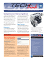
June 2002
Volume 4, No. 6
A monthly publication for GM Dealership Service Professionals
Compression Sense Ignition
An all-new 2.2L engine (RPO L61, VIN F)
is used in Pontiac Sunfire and Grand Am,
Oldsmobile Alero and Chevrolet Cavalier for
2002. This is an aluminum 4-cylinder engine
with four valves per cylinder. It uses a speed
density fuel injection system and a waste
spark electronic ignition system.
Although waste spark ignition is familiar
technology, the L61 gives it a new twist –
L850 Compression Sense Ignition (CSI).
CSI enables the Powertrain Control
Module to determine proper engine phasing
(cam position) without the use of a separate
camshaft position sensor.
Components
CSI’s modular design is similar to the
system used on the premium V6 and V-8
engines, covered in the January 2000
TechLink. Both systems house nearly all the
major ignition system components in a single
cassette, although only the L61 engine uses
compression sense.
The ignition cassette is mounted directly
over the spark plugs, requiring only a
connector spring and insulating boot to
transfer the ignition energy to the spark
plugs. The cassette houses two ignition
coils. Each coil sends ignition energy to two
paired cylinders at the same time, one
cylinder on its exhaust stroke and the other
cylinder on its compression stroke. Cylinders
1 and 4 are paired on one coil and cylinders
2 and 3 on the other.
Spark Polarities
One spark plug in each pair always fires
from the center electrode to the side
electrode. The other always fires from the
side electrode to the center electrode.
One cylinder’s firing voltage rises in a
negative direction, relative to engine ground
on the way to its final breakdown voltage. It
then quickly breaks over in a positive
direction back toward ground until the spark
line is established. The other cylinder’s firing
voltage rises in a positive direction, relative
to engine ground, then quickly breaks over in
a negative direction back toward engine
ground until the spark line is established.
The polarity characteristics of the spark
events are one part of the information
reflected in the CSI signal.
continued on page 3
Techline News
Service Information:
New and Improved
Contents
Compression Sense Ignition . . . . . . . . . . . . . . .1
The next time you use your Techline
CDs, or visit the Service and Parts
Operations website,
(http://service.gm.com), you will find a
new appearance and some very useful,
new features.
A new graphic design is used in
common between the CD and the web,
along with some new enhanced features.
The redesign is in response to user
feedback. The changes appear on CD
version 12, issued in April 2002, and were
added to the Internet website during the
month of May.
The materials contained on the CDs,
and the material found under the Service
Information tab on the website, are
identical in every way. The design is the
same, and the way they perform is the
same. Now, if you have to switch from one
to the other, you won’t be confused by two
different formats.
Service Information: New and Improved . . . . . . .1
Class 2 Corner . . . . . . . . . . . . . . . . . . . . . . .2
Corvette Magnetic Selective Ride Control . . . . . .4
Theft Deterrent Application Update . . . . . . . . . .4
Airbag Zoning . . . . . . . . . . . . . . . . . . . . . . . .5
The first change you need to be aware
of is the name. Previously, it was SI 2000,
which reflected the year it was introduced.
To avoid having to change the name every
year or so, it will now be known simply as
SI, or Service Information. The types of
service materials available are essentially
unchanged, however.
The new SI application has been
streamlined. You may notice the CD
version no longer has a choice between
Enhanced and Basic versions. There is only
one version, and it’s extremely user
friendly.
continued on page 2
1
Tech Tips
Carpet Separates from Sill Molding . . . . . . .5
A/C Liquid Line Rubbing . . . . . . . . . . . . . . .5
Wheel Speed Sensor Clips . . . . . . . . . . . . .6
Cardan Joint Lubrication . . . . . . . . . . . . . .6
Mildew Odor or Wet Carpet . . . . . . . . . . . .6
Pontiac Vibe Service Tips . . . . . . . . . . . . . .7
Third Door Handle . . . . . . . . . . . . . . . . . . .7
Bulletins . . . . . . . . . . . . . . . . . . . . . . . . . . . .8
Service and Parts Operations
Techline News
continued from page 1
The website home page is shown here.
You can make your choices from the
thumbtabs at the top of the screen or from
the bulleted list below.
Whether you are accessing the
application from the CD or the web, you
will see the page shown here.
The top half of the page allows you to
“build” the vehicle for which you want
information. The major change is that you
can now do this on one page instead of
three separate pages. In some cases, you
may also want to click the Optional Vehicle
Information button to further describe the
vehicle you’re working on.
If you choose to view Bulletins,
Campaigns and Preliminary Information,
the release date is now listed.
TIP: Dashes are not required when
searching directly for a bulletin or
campaign.
The buttons in the bottom half of the
page look and perform exactly as they
always have, with one exception. There is
a new button marked Y+P+K , This button
allows you to search for bulletins by
specifying a year range, the vehicle
platform, and a keyword. This is handy if
you remember a bulletin, but are not sure
of the exact year it was issued. If it falls
within the range you specify, you’ll find it
quickly.
And finally, document printouts will now
include the year, make and model of the
vehicle specified.
New Features Being Added
Once the vehicle has been “built,” you
will have the opportunity to choose from
the available service information. For now,
the first choice is Service Manual and
Bulletins. As 2003 vehicles are added, you
will also be able to view the warranty book,
owner’s manual and supplements.
Although much of this information is
taken from owner literature, it is
reformatted for the web. This means you
can select just the page(s) you need, and
they will load quickly.
The Labor Time Guide will be integrated
into SI by the 4th quarter of 2002. Because
the new version will be presented in
service manual style, there is no longer a
need for a separate PDF version. And it will
include a keyword search capability.
Update Schedule
SI, Owners Manuals, and Labor Time
Guide will be updated on a regular basis as
a package.
Currently SI (web) is updated once a
week. SI updates to the GM ACCESS
server will occur every second Monday. If
there are updates to the LTG or the
Owners Manual, they will be included with
SI updates.
– Thanks to Bob Savo and Tom Tippen
The Class 2 bus can be wired in one of
two ways, Star configuration and Loop
configuration. Both have their advantages
and disadvantages.
The Star configuration connects each
controller using a single wire from each
computer. The wires are spliced together at a
single location using a Splice Pack (also
called a Star Connector). A splice pack is a
connector-like component that uses a
removable bus bar that connects all of the
controllers together. The advantage of the
Star configuration lies in its relative ease of
diagnosis. The splice pack provides a
convenient location in which to diagnose
electrical problems associated with the Class
2 bus. The disadvantage is that there is no
built-in redundancy to the system. If an open
occurs on one of these wires, the controller
will no longer be able to communicate on the
bus.
The Loop configuration uses two wires
connected to each controller. One of the
wires will connect to the next controller on
the loop while the second wire connects to
the previous one. This creates a loop of
controllers all holding hands, as it were. Each
wire carries identical information, so there is
no specific “input” or “output” wire. The
advantage is that with two wires, there is
redundancy built into the system. If an open
occurs on one wire, the message can still be
sent via the second one. The disadvantage is
in the relative difficulty of diagnosis. Because
there is no central location where the bus
comes together, you must isolate sections of
the bus to do electrical checks.
– Thanks to Mark Harris
2
GM TechLink is a monthly magazine for
all GM retail technicians and service
consultants providing timely information
to help increase knowledge about GM
products and improve the performance
of the service department. This
magazine is a companion to the GM
Edge publication.
Publisher & Editor:
Mark Stesney
GM Service Operations
[email protected]
Technical Editor:
Jim Horner
[email protected]
1-248-816-3641
Production Manager:
Marie Meredith
Desktop Publishing:
Greg Szpaichler, MediaWurks
[email protected]
FAX number:
1-248-649-5465
Write to:
TechLink
PO Box 500
Troy, MI 48007-0500
GM TechLink on the Web:
http://service.gm.com
General Motors service tips are intended
for use by professional technicians, not a
"do-it-yourselfer." They are written to
inform those technicians of conditions
that may occur on some vehicles, or to
provide information that could assist in
the proper service of a vehicle. Properly
trained technicians have the equipment,
tools, safety instructions and know-how
to do a job properly and safely. If a
condition is described, do not assume
that the bulletin applies to your vehicle
or that your vehicle will have that
condition. See a General Motors dealer
servicing your brand of General Motors
vehicle for information on whether your
vehicle may benefit from the information.
Inclusion in this publication is not
necessarily an endorsement of the
individual or the company.
Copyright© 2002 General Motors Corporation
All rights reserved.
Return to page 1
Compression Sense Ignition
continued from page 1
Ignition Control Module
Ignition Cassette Disassembled to Reveal Components
Compression Sense
At the moment an ignition coil fires, a
growing voltage potential is created across
the gap of both plugs. After about 10
microseconds, the voltage reaches each
plug’s breakdown voltage level. Breakdown is
the point at which the air gap ionizes and
conducts current, causing the spark to occur.
The breakdown voltage level is determined in
part by the pressure within the cylinder.
More voltage is required at a higher cylinder
pressure.
CSI Components
Ignition
Control Module
Connector
these capacitor plates is connected to the
ignition secondary outputs. The other side is
connected to a resistor network. As current
flows on the capacitor plates, a voltage is
created on this resistor. The voltage pattern
measured across this resistor is what makes
up the information in the CSI signal.
Firing Order 1/4 - 3/2 - 4/1 - 2/3
Spark Plug Boots
A cylinder on its exhaust stroke has less
in-cylinder pressure than a cylinder on its
compression stroke. Because of these
uneven pressures, the spark plug of the
cylinder on its exhaust stroke will break
down first (by a few microseconds), and will
spark first.
The order of the spark plug gap
breakdown events for the paired cylinders is
yet another characteristic that is reflected in
the CSI signal.
The CSI Sensor
The L850 utilizes a unique Compression
Sense Ignition sensor to detect the polarity
events and the breakdown events in the
secondary ignition circuits of each pair of
cylinders.
This is accomplished by creating virtual
capacitors between the secondary coils and
the EI module’s electronics. One side of
As the chart above shows, when the 1/4
coil fires, as cylinder 1 is on compression, the
event will generate a negative, then positive
CSI signal. This negative then positive CSI
signal will cause the CSTO chip inside the EI
module to send a CAMOUT high signal.
Cylinder on
Exhaust
(waste spark)
fires first
Cylinder on
Compression
fires second
4 - voltage
1 + voltage
2 - voltage
3 + voltage
1 + voltage
4 - voltage
PCM Logic
3 + voltage
2 - voltage
A variable reluctance crankshaft position
(CKP) sensor is mounted in the engine block
near the crankshaft. The crankshaft has
seven machined notches, six of which are
evenly spaced. The 7th notch is positioned at
50 degrees ATDC of cylinder 1/4 and is used
by the PCM as a sync pulse.
Cover
Coil
Housing
recognizes unique characteristics of the CSI
input signal, then decides whether to send a
CAMOUT high or CAMOUT low signal to the
PCM.
The resistor network allows only the high
frequency edge of the plug gap breakdown
voltage to pass through for measurement.
We know that cylinders fire in pairs, and
from the earlier study on polarity, we know
that the voltage of one plug moves toward
positive while its pair moves toward negative.
And from the breakdown discussion, we
know that the plug in the cylinder on the
exhaust stroke fires slightly before the one on
the compression stroke. These relationships
can be seen in the accompanying chart.
The CSI signal will reflect the polarity and
timing of each cylinder’s spark plug
breakdown voltage event.
Now that we have seen all the various
pieces of information contained in the CSI
signal, as well as the method in which it is
acquired, let’s pull it all together and see how
it is processed.
When the 1/4 coil fires, as cylinder 4 is on
compression, the event will generate a
positive, then negative CSI signal. This
positive to negative CSI signal will cause the
CSTO to send a CAMOUT low signal.
The 2/3 cylinder pair works the same way.
The engine always starts firing the 2/3 coil
first during cranking. Charging of the 2/3 coil
always begins near the 2nd crank notch.
Charging of the 1/4 coil always begins near
the 5th crank notch.
Once the ignition process has started with
the 2/3 coil, the PCM will look for the
sequence of CAMOUT signals from the EI
module to determine engine phasing. After 2
crankshaft revolutions, all four cylinders will
have fired and generated the 4 CAM ID bits.
continued on page 4
Firing Voltage Polarities
EST Signal
Coil fires
The CSTO
The EI module houses the CSI input
signal logic electronics called the
Compression Sense Time Out (CSTO) chip.
The CSTO electronics are responsible for
interpreting the CSI input signal and creating
a 5V square wave output called a CAMOUT
signal.
Here’s how the CSTO chip logic works.
The first EST rise of either cylinder pair alerts
the CSTO circuitry, and the CSTO chip looks
for the CSI input signal. The CSTO chip
3
Cylinder
on waste
Firing
voltage
rises in
Positive
direction
Breaks over
in a Negative direction
Cylinder on compression
Firing
voltage
rises in
Negative
direction
Breaks over
in a Positive direction
Return to page 1
Compression Sense Ignition
continued from page 3
These sequences of high and low
CAMOUT signals are read by the PCM as a
series of 4 data bits – a 1 bit if CAM is high
and a 0 bit if CAM is low. The bits will be in
the order of 1001 if cylinder 3 came up on
High CAMOUT Signal Generation
Waste
firing
voltage
breaks
over
Coil Fires
Compression
firing
voltage
breaks
over
Voltage moves
toward positive
CSI Signal
Voltage moves
toward negative
compression first, or 0110 if cylinder 2 came
up on compression first, upon initiation of
ignition during cranking.
The Tech 2 scan tool displays these bits
as a parameter (Saturn only) using the
following path: / Powertrain / Data Display /
Engine Data Display / Misfire Data /
Calculated Compression Output (CCO).
The Tech 2 will actually display 8 bits, but
only the lower 4 bits are used. The first 4 bits
always remain as zeros.
Special Conditions
The PCM needs to take into account
engine operating conditions during which the
in-cylinder pressures for the pairs can be
nearly equal. During deceleration, the
pressure of the compressing cylinder can be
as low as, or lower than, that of the cylinder
on its waste stroke. This condition would of
course render the CSI signal information
invalid. For this reason, the PCM will
consider the CSI signal valid only during
certain MAP ranges.
TIP: This brief explanation shows how the
Compression Sense Ignition system works, as
well as the inherent information the CSI signal
provides. A full-length version of the story is
available on the internet at
www.mat1424.com. This site is sponsored
by GM Marketing Area Team 1424 in Phoenix,
AZ. In the left menu, select Downloads. Then
select Compression Sense Ignition Part 1. You
can then select the article, plus the
illustrations. There are plans to offer Parts 2
and 3 on the website at a later date.
– Thanks to Jim Garrido, member of
International Automotive Technicians
Network, and Kevin Schmidt, Delphi
New Vehicle Preparation – Corvette
Magnetic Selective Ride Control
For 2003, Magnetic Selective Ride Control
will be available on the Chevrolet Corvette.
Briefly, when the vehicle is being driven,
various sensors pick up data which is
processed by a control module. Using pulsewidth modulation, the control module varies
an electromagnetic field in each damper,
which affects the thickening of the magnetorheological fluid, within a millisecond. A
similar Cadillac system was described in the
January 2002 TechLink.
When the ignition is turned off, the
dampers offer very little damping. So, the
cars are shipped from the factory with the
suspension snugged down until the jounce
bumper contacts a temporary plastic stuffer
in each damper.
TIP: The stuffers must be removed during
new vehicle prep. Failure to do so will result
in customer dissatisfaction with the vehicle’s
ride quality.
To remove the stuffers, lift the vehicle,
allowing the wheels to hang free. This will
extend the dampers.
At the front, steer the wheel in the
direction away from the side you’re working
on. Reach up from below, behind the tire.
At the rear, reach up from below, behind
the tire.
At each wheel, compress the rubber dust
boot. Pull the yellow tab to remove the
stuffer, then discard.
TIP: After removing the stuffer, be sure to
pull the dust boot down to cover the upper
end of the damper tube, to avoid damage.
TIP: The stuffers should not be reinserted
for temporary transport, such as on a flatbed
hauler. The stuffer is effective only if the
suspension can be snugged down enough
for the jounce bumper to contact the stuffer.
This is generally not possible on a flatbed
hauler.
– Thanks to Brad Thacher and Dave Peacy
Theft Deterrent Application Update
Please add Camaro models for years 1998-1993 to the Theft Deterrent Application chart on page 4 of your April 2002 TechLink.
86/87 1988 1989 1990 1991 1992 1993 1994 1995 1996 1997 1998 1999 2000 2001 2002 2003 2004 2005
*
Chevrolet Camaro
No system available for model
Passkey II (PK2) or VATS, PASS-Key
*
Vehicle line is not in use
Passkey III (PK3)
?
System is undetermined
Passkey III+ (PK3+)
Opel Immobilizer
Easykey
*
*
Passlock
4
Return to page 1
Airbag Zoning
Typical airbag zones
Early airbag systems consisted of a
steering wheel airbag, a control module,
several sensors and a wiring harness to tie
them together. When one of the airbag
system components or another vehicle
component in the general area needed
service, it was necessary to disarm the entire
airbag system, to prevent unwanted
deployment.
Now, airbag systems have grown to
include (on the 2003 Cadillac CTS, for
example) a steering wheel airbag, an IP
airbag, two side airbags, two roof rail airbags,
two seat belt pretensioners, up to four
sensors including a sensing and diagnostic
module, and numerous wiring harnesses,
spread widely throughout the vehicle.
Because the chances are greater than
ever that you will encounter an airbag
component when performing a service
procedure, vehicles are now divided into as
many as a dozen different SIR Disabling and
Enabling zones. By following the proper
procedure, you can easily disable only those
airbag components that are in the area
where you’re working. And when you are
finished, you can just as easily enable the
zone. Depending on the complexity of the
vehicle, this can amount to a considerable
time savings.
TIP: The 2003 Cadillac CTS was the first
vehicle to reach the market with the zone
system; all 2003 GM cars and trucks will be
included when they arrive in the upcoming
months.
A/C Liquid
Line Rubbing
On some 2002 Buick Century and
Regal vehicles, the A/C liquid line may
rub through at the transaxle side cover
pan. This may not occur until the vehicle
has 20,000 miles (32,200 km) on it.
TIP: Because vehicle platforms are not all
laid out similarly, the number of zones will
vary from vehicle to vehicle, but they all
follow the same naming/numbering scheme
for sake of consistency.
Dealing with Codes
–
–
–
–
–
“Build” the vehicle
Restraints
SIR
Diagnostic Information and Procedures
SIR Disabling and Enabling Zones
Disabling a zone will cause a Current
diagnostic code to set. Enabling the zone will
move the code to History. Before returning
the vehicle to the customer, you should clear
all History codes.
For specific procedures, follow this path:
Other Information
–
–
–
–
–
“Build” the vehicle
Restraints
SIR
Repair Instructions
SIR Disabling and Enabling Zone 1
Carpet
Separates from
Sill Plate Molding
Airbag zoning was discussed in a recent
IDL broadcast. For a replay of it, look for
course number 10260.14D in the broadcast
schedule.
– Thanks to Ken McLaughlin
Retainer Positioned on Clip
On some 1997-2001 Buick Centurys or
Regals, the carpet may pull out from under
the rear door sill plate molding.
The repair procedure is explained in depth
in bulletin 01-08-110-004. These are the
highlights.
Mark the retainer’s location on the carpet.
Then, use an auto trim stapler to attach the
retainer to the carpet. Use three 12 mm (1/2
in.) galvanized staples.
– Thanks to Wayne Zigler
TIP: The service information for all
vehlcles follows the same organization, so
the paths are all identical.
To learn more about airbag zones in SI
2000, follow this path:
Part number 10414280 includes two
plastic retainers, one for each side. With the
sill exposed, position a retainer over the sill
plate retaining clip with the wide portion of
the retainer toward the center of the vehicle.
TIP: To avoid this condition, check
this area during new vehicle predelivery
inspection.
You will find separate instructions for each
zone included on the vehicle you’re servicing.
Retainer Stapled to Carpet
Carpet Held by Retainer
TIP: The bulletin recommends auto trim
staples. If you substitute short trim screws
or rivets, file the excess off the back side to
avoid creating noise.
Hook the retainer over the clip to retain
the carpet in place. Install the weatherstrip
and sill plate to complete the repair.
– Thanks to Wayne Zigler
5
Return to page 1
Wheel Speed Sensor Clips
This affects Buick Century and Regal,
Oldsmobile Intrigue, Pontiac Grand Prix and
Montana, and Chevrolet Monte Carlo, Impala
and Venture.
The wiring from the wheel speed sensor
is a pigtail, about 4 inches (100 mm) long,
terminated with a connector. The connector
clips to a bracket on the steering knuckle.
During the 2001 model year, the sensors
were changed.
Connector clipped to bracket
Pinch here
with pliers
to remove
When you replace a wheel speed
sensor/wheel bearing assembly (for bearing
noise, WSS code, etc.), you must determine
which type of sensor is on the vehicle and
replace it with the same kind. Check the
parts book for details.
Sensor wire lead location with the new W-clip
At the time the clips were changed, the
mounting orientation of the sensor was also
changed. Sensors with the old SS clip were
mounted with the wire lead near the 6:00
o’clock position. New sensors with the Wclip are mounted with the wire lead near the
2:00 or 10:00 o’clock position, depending on
which side of the vehicle it’s mounted. This
moves the lead away from the lower ball
joint attachment, as shown in the
accompanying photo.
– Thanks to Wayne Zigler
Cardan Joint Lubrication
Early production used a stainless steel
(SS) clip on the wiring connector, which could
be removed from the bracket simply by
pulling. Later production uses a plastic Wclip, which requires ordinary pliers for
removal.
TIP: Do not replace either style of clip
with the other. They are not interchangeable.
12429204 (old style with SS clip-top left) and
12429205 (new style with W-clip-bottom right)
Some 1994-2002 trucks, such as the
Chevrolet S-10 and GMC Sonoma extended
cab with L35 V-6, use a propeller shaft that
has double cardan type U-joints. A similar
shaft is used as a service replacement on
1999-2002 2-wheel drive, automatic,
extended cab Sierra and Silverado trucks.
Premature wear of the cardan joint ball and
socket can result in noise and vibration at
road speeds.
Cardan Joint Cross Yoke Grease Fitting and
Needle-Type Applicator
Premature wear may be caused by
inadequate lubrication. A grease passage in
each cross yoke should be lubricated at
normal chassis lubrication intervals.
You will need a needle-type grease gun
adapter such as Plews/Stant 99-009 or 05025, available locally. Use Chassis Lubricant,
P/N 12377985 (88901242 in Canada) or
equivalent. The slip yoke should also be
greased at the zerk fitting. SI 2000 will be
updated to include propshaft lubrication
service.
– Thanks to Dan Oden
Mildew Odor or Wet Carpet
Owners of some S/T pickups and utilities
and Bravada may comment on mildew odor
or wet carpet in the front passenger area.
There are three common causes.
New bearing assembly on left, old on right
Water Backing Up
at Plenum Drain
Too much sealer at the plenum drain area
can act as a dam, allowing water to back up in
the plenum. It seeps around the air box seal
or around the lower right air box mounting
screw. Reduce the ridge of sealer to a height
of 1/4-inch (6.3 mm) or less with a utility knife.
Voids in Plenum
Seam Sealer
Use a mirror to examine the inside of the
6
plenum for possible voids in the seam sealer.
Seal any voids following instructions in the
service manual.
HVAC Recirculation
(Air Box) Door Left Open
With the HVAC controls set to MAX A/C,
the recirc door opens upward. In extreme
conditions, water can pool on top of this door
and spill into the vehicle. If the ignition is
turned off with the controls set in MAX A/C,
the door remains up. Locate an intermittent
entry point for the water. Inform customers
to turn the HVAC to regular A/C or OFF
before turning the ignition off.
– Thanks to Monica Pruett
Return to page 1
Pontiac Vibe
Service Tips
The 2003 Pontiac Vibe has several
unique service features you should be
aware of.
Automatic
Transmission Fluid
Use only ATF T-IV transmission fluid,
not Dexron III. Using the wrong fluid can
cause harsh shifting.
Power Steering System
Use only Dexron® III transmission fluid,
not power steering fluid. Failure to use the
proper fluid can cause leaks and damage
to the power steering system.
Coolant
Although the Vibe’s coolant is tinted
red, it is conventional ethylene glycol, not
Dex-Cool. The cooling system is filled at
the factory with a 50/50 mixture of water
and ethylene glycol antifreeze. This coolant
solution provides freezing protection to 36°C (-33°F). Add Dex-Cool coolant to the
coolant reservoir when the coolant level is
low. (Mixing green ethylene glycol to the
factory red ethylene glycol results in
brown coolant, which may be a customer
dissatisfier.) When the system is flushed at
the recommended intervals, fill the system
with green-colored ethylene glycol coolant.
EVAP Testing
If you use the J-41413-200 Evaporative
Emission System Tester (EEST) (December
2001 TechLink), to locate a leak, you will
notice smoke coming from the drain hose.
This is a normal condition. In order to
check the system for leaks, you must
connect the EEST to the EVAP service
port. Bend the drain hose double, while
crimping it with locking pliers or equivalent
before testing.
TIP: Because the Vibe EVAP system is
similar to the Prizm, this EVAP testing
information applies to the Prizm as well.
– Thanks to Jeff Strausser
and Russ Dobson
Third Door Handle
Owners of some 1996-2002 extended
cab S-10 and Sonoma pickups may
comment on excessive effort or breaking of
the third door handle. This may be caused
by improper placement of the attachment
clips and/or binding at the top latch.
Remove the door trim panel and release
both lock-rod clips. Secure the upper rod
clip (on the right side of the door handle)
first. Position the upper rod clip 10.5-12.0
mm (approximately 11-12 threads showing)
from the end of the rod and lock it in place.
Position the lower lock-rod clip (left ) where
it falls after the upper clip is in place, usually
5.0-6.0 mm (5-6 threads showing) from the
end of the rod. Make sure the upper striker
is not bound against the latch. If it is, you
must push the door inboard to release the
latch. To correct a bound latch, adjust the
striker by loosening two bolts at the top, so
the striker is centered in the latch. Do not
bend the striker.
– Thanks to Monica Pruett
Latch and striker
Upper and lower rod clips
7
Return to page 1
Bulletins – May 2002
This review of service bulletins released
through mid-May lists the bulletin number,
superseded bulletin number (if applicable),
subject and models.
Case Shift Control Switch); 1999-2002
Chevrolet and GMC C/K Pickup and Utility
GENERAL INFORMATION:
02-05-22-001; Revised Brake Specifications;
1997-2002 Chevrolet Malibu, Oldsmobile
Cutlass and Alero, Pontiac Grand Am
99-00-84-021C; replaces 99-00-84-021B;
Expediting Parts; 2003 and Prior Passenger
Cars and Trucks
02-00-89-002; Information for Dealers on
How to Submit a Field Product Report; 2003
and Prior Passenger Cars and Trucks
BRAKES:
02-05-23-001A; replaces 02-05-23-001;
Uneven Brake Pad Wear (Replace Caliper
Mounting Plate and Install New Rear Brake
Shield); specified 1995-2001 Chevrolet and
GMC MD Trucks with Four-Piston Rear Disc
Brakes (RPO JNC)
02-07-30-013; Incorrect Transmission Shifts,
Poor Performance of Engine, Transmission
Slipping, SES Lamp Illuminated; DTC P0756,
P0757 (Clean Transaxle Valve Body and Case Oil
Passages of Debris); specified 2001-02 Vehicles
with 4T65E Transmission (RPOs M15, MN3,
MN7, M76)
02-07-30-014; Servicing 4T65-E Transaxle
Spacer Plate and Gaskets; specified vehicles
1997-2002 with 4T65-E Transaxle (RPOs MN3,
MN7, M15, M76)
02-05-25-001; Yaw Rate Sensor/Lateral
Accelerometer Replacement; 2002 Cadillac
Escalade EXT with Stabilitrak® (RPO JL4)
02-07-30-015; Revised DTC P0713; 2002
Buick Century, Regal, LeSabre, Chevrolet
Impala, Monte Carlo, Venture, Oldsmobile
Aurora, Intrigue, Silhouette, Pontiac Bonneville,
Grand Prix, Montana with 4T65-E Automatic
Transaxle
02-00-89-003; Priority Access Service
System (P.A.S.S.); 2003 Chevrolet and GMC
MD Conventional Cab Models
ENGINE/PROPULSION
SYSTEM:
02-07-31-002; Intermittent Engine No Crank
(Repair Wiring and Install Wiring Protector);
specified Chevrolet and GMC MD Trucks
02-00-89-004; Revisions to Courtesy
Transportation Program; 2002 and Prior
Passenger Cars and Trucks
99-06-02-012D; replaces 99-06-02-012C;
Rust in Cooling System, Heater Inoperative,
Blows Cold Air, Engine Overheats (Flush
Cooling System); 1996-2000 Chevrolet and
GMC S/T, Oldsmobile Bravada, 1998-2000 GMC
Envoy with 4.3 L V6 (VINs W, X – RPOs L35,
LF6)
02-00-89-002A; replaces 02-00-89-002;
Information for Dealers on How to Submit a
Field Product Report; 2003 and Prior Passenger
Cars and Trucks
02-00-89-005; Dealer Disclosure
Requirements; 2003 and Prior Passenger Cars
and Trucks
02-00-90-002; Lubrication of Propeller Shaft
Double Cardan CV Type U-Joint Centering Ball
and Seat; 1994-2002 Chevrolet and GMC S
Extended Cab Pickup with V6 Engine, C
Extended Cab Pickup with Automatic
Transmission (RPO M30)
HVAC:
00-01-38-011A; replaces 00-01-38-011; Poor
Heat with Cold Outside Temperatures at Low
Engine RPM (Install Auxiliary Coolant Pump);
1997-1999 Chevrolet Venture, Oldsmobile
Silhouette, Pontiac Trans Sport, 1999 Pontiac
Montana
00-01-38-011B; replaces 00-01-38-011A;
Poor Heat with Cold Outside Temperatures at
Low Engine RPM (Install Auxiliary Coolant
Pump); 1997-1999 Chevrolet Venture,
Oldsmobile Silhouette, Pontiac Trans Sport,
1999 Pontiac Montana
STEERING:
01-02-118-001A; replaces 01-02-118-001;
Parts Restriction/Exchange Program for
Quadrasteer™ Components; 2002 Chevrolet
and GMC Vehicles with Rear Wheel Steer
(Quadrasteer) (RPO NYS)
00-06-01-006B; replaces 00-06-01-006A;
Engine Tick Noise (Purge Air from Valve Lifters);
1999-2002 Chevrolet Tracker with 2.0L or 2.5L
Engine (VINs C, 4 – RPOs L34, LE8)
00-06-05-049A; replaces 00-06-05-049;
Various Driveability Symptoms – MIL Illuminates
Intermittently, DTCs Set, Engine Will Not Start
(Repair Wires);
1997-2001 Buick Century, Regal, 2000-2002
Chevrolet Impala, Monte Carlo, 1999-2001
Pontiac Grand Prix
01-08-57-007A; replaces 01-08-57-007;
General Waterleak Diagnosis Guide; 1999-2002
Chevrolet Malibu, Oldsmobile Alero, Pontiac
Grand Am
02-08-42-002; Headlamp Condensation;
2002 Chevrolet Avalanche
02-08-42-004; PRNDL Display Reduced
Visibility for Approximately One Minute; 2002
and Prior Passenger Cars and Trucks with Auto
Headlamp Control and Vacuum Fluorescent
PRNDL Indicator Instrument Cluster
02-08-46-004; Cellular Error Messages
Received When Trying to Connect to OnStar®;
2000-02 Passenger Cars and LD Trucks with
Factory Installed OnStar®
01-06-04-049A; replaces 01-06-04-049;
White Exhaust Smoke During Start-Up (Replace
Engine Coolant Sensor ECT); specified 2000-02
Chevrolet and GMC MD Trucks
02-08-50-002; Driver Seat Movement During
Acceleration and Braking (Replace Adjuster
Assembly); 1997-2002 Chevrolet Corvette with
Power Seats (RPO AG1 or AG2) built prior to
breakpoint
02-06-01-010; Serpentine Belt Identification
and Diagnosis; 2001-02 Chevrolet and GMC C/K
HD Pickup Models with 6.6L Duramax™ Diesel
Engine (VIN 1 – RPO LB7)
02-08-59-002; Rattle Type Noise Coming
from Center of Dash (Remove Cowl Insulator
Clip and Insulate Mounting Stud); 2002
Chevrolet and GMC C/K Pickup and Utility,
Cadillac Escalade with Gas Engine
02-06-01-012; Revised Harmonic Balancer;
2002 Chevrolet and GMC S/T Utility, Oldsmobile
Bravada
02-06-01-014; Revised Lower Intake
Manifold Installation; specified vehicles 19962002 with 3.1L or 3.4L Engine (VINs J, M, E –
RPOs LG8, L82, LA1)
02-02-32-005A; replaces 02-02-32-005;
Excessive Noise from Power Steering System
While Turning or Under Light Braking (Replace
Power Brake Booster Inlet Hose); 1999-2002
Chevrolet and GMC M/L Van Models
02-06-01-015; Low Oil Pressure and New Oil
Level Indicator; 2001-02 Chevrolet and GMC
C/K, G, C6-7 MD, B7 MD School Bus Models
with 8.1L Engine (VINs E, G – RPO L18)
DRIVELINE AXLE:
TRANSMISSION/TRANSAXLE:
02-04-21-003; Revised DTC B2725; 19992002 Chevrolet and GMC C/K Pickup and Utility
Models, 1999-2000 Cadillac Escalade, 2002
Cadillac Escalade, Escalade EXT with NVG
236/246 Transfer Case (RPO NP8)
01-07-30-023B; replaces 01-07-30-023A;
Harsh 1-2 Upshift, SES, MIL, or CEL Illuminated,
DTC P1870 Set (Replace Valve Body); 1996 Buick
Roadmaster, Cadillac Fleetwood, 1996-2000
Chevrolet Camaro, Corvette, LD Trucks, Pontiac
Firebird, GMC LD Trucks, Oldsmobile Bravada,
1999-2000 Cadillac Escalade with 4L60-E
Automatic Transmission (RPO M30)
02-04-21-004; “Service 4WD” Indicator
Illuminated, DTC B2725 Set (Replace Transfer
BODY AND ACCESSORIES:
8
02-08-61-001; Clicking/Creaking Noise from
Front of Vehicle (Apply Penetrating Threadlocker);
2000-02 Chevrolet Impala, Monte Carlo
02-08-64-007; Third Door Hard to Open
and/or Handle Breakage (Adjust Lock Rods);
1996-2002 Chevrolet and GMC S/T Extended
Cab Pickup Models
02-08-64-008; Uncommanded Movement of
Outside Rearview Mirrors (Replace Mirror
Actuator); 2002 Chevrolet and GMC S/T Utility
Models, Oldsmobile Bravada, with Memory
Mirrors (RPO D25)
02-08-66-004; Paint Rub Through on Liftgate
Around Edge of License Plate Housing/Pocket
(Install Insulating Seal/Gasket); 2002 Chevrolet
and GMC S/T Utility, Oldsmobile Bravada
02-08-67-002; Headliner or Roof Rattle
(Replace Roof Drain Channel with New Design
Channel); 2002 Cadillac Escalade, Chevrolet and
GMC C/K Utility Models
Return to page 1