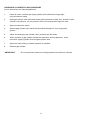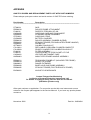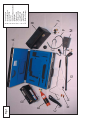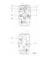
1
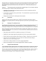
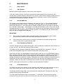
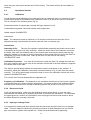
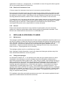
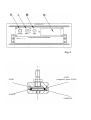
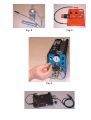
GAS-TEC ® MK.III
Flame Ionisation Monitor
Type 99F64001
Operating Manual
Telegan Gas Monitoring
(A division of Crowcon Detection Instruments Ltd)
2 Blacklands Way
Abingdon Oxfordshire
OX14 1DY
Tel: 44 (0)1235 553057 Fax: 44 (0)1235 553062
TELEGAN GAS MONITORING GASTEC MK.III OPERATING MANUAL
CONTENTS
INDEX
PAGE
1.
INTRODUCTION
5
3
2.
GENERAL DESCRIPTION OF THE INSTRUMENT
3
5
2.1
2.2
Operational Features
Measuring Ranges
3.
SAFETY
4.
4.1
4.2
4.3
4.4
4.5
4.6
4.7
Operating Instructions
Starting Up
Measuring Ranges and Communications
Use of the Instrument
Sampling Systems
Shut Down
Setting for True Ambient Level
Oxygen Depleted Samples
5.
5.1
5.1.1
5.1.2
5.1.3
5.1.4
MAINTENANCE
Daily Checks
Gas Cylinder
Internal Batteries
Filter Assembly
Probe Maintenance
9
7
5.2.
5.2.1
5.2.2
5.2.3
5.2.4
5.2.5
Operational Checks
Calibration
Electronic Check
Hydrogen Leakage Tests
Removal of Instrument Cover
General
8
10
6.
6.1
6.2
REFILLABLE HYDROGEN CYLINDER
Maintenance
Filling with Hydrogen
9
11
APPENDIX
Spare and Replacement Parts List
with Part Numbers.
13
11
6
4
6
8
11
9
ILLUSTRATIONS
Fig. 1
Fig. 2
Fig. 3
Fig. 4
Fig .5
Fig. 6
47227A
5
7
The Gas-Tec and Accessories
Front and Rear Views of Instrument
Top View of Instrument
Calibration Kit
Gas-Tec Calibration Adjustment
Hydrogen Filling Apparatus
Filter Assembly
23
1.
INTRODUCTION
The Telegan Gas-Tec is a self-contained lightweight, portable instrument for detecting and
measuring total hydrocarbon gas concentrations down to parts per million (ppm) levels.
With a fast response time of two to three seconds and good long term stability, it can be used for a
wide range of applications which include:
•
•
•
•
•
Leakage surveys of buried gas distribution systems.
Detection of leaks in piping and apparatus containing hydrocarbon gases.
Measurement of atmospheric hydrocarbon concentrations at low levels.
Continuous 'on site' monitoring.
Tracing migration of biogenerated gas from landfill sites or underground workings.
2.
GENERAL DESCRIPTION OF THE INSTRUMENT
2.1
Operational Features
The operation of the instrument is based on the principle of 'flame ionisation.' The presence of
hydrocarbons in a hydrogen flame produces an electrical (ionisation) current effect which can be
detected and amplified by suitable electronic circuits.
The instrument is illustrated in figs 2 and 3 and consists of a housing (A) below which is
mounted the gas cylinder (B) for the supply of hydrogen to the flame ionisation detector (FID).
At one end of the housing are various components for starting up and running the instrument.
These comprise a pressure regulator and cylinder pressure gauge (C), sample air flow control
(D) and flowmeter (E), igniter button (F), battery charging socket (G) and calibration control
under the label at (P). At the other end (Fig. 3) are the filter housing and connection for the
handprobe (H), loudspeaker and socket for earphones (I), and the audio output control (O).
Visible on the top of the housing are the battery condition meter (K), combined On/Off and
Range switch (L), zero adjuster (M) and gas concentration meter (N).
Incorporated in the instrument is a suction pump running off the same rechargeable batteries
which supply the electronic circuits. Connected to this by a flexible plastic tube is a probe
handle to which alternative interchangeable probes can be attached (see section 4.4).
Available for the instrument are a special automatic battery charger, earphones and spare
hydrogen cylinder, all of which can be accommodated in the fitted carrying case (see fig 1).
The presence of gas is indicated by an increase in meter reading coupled with an audible signal
whose pitch rises with increasing gas concentration. The audio output level can be controlled by
the knob (O).
The running time of the instrument is approximately 60 hours per filling of the gas cylinder and
up to 15 hours per charge for the batteries.
2.2
Measuring Ranges
The instrument has two ranges and in standard form is calibrated for methane in air
concentrations of 0-1,000 ppm and 0-10,000 ppm (parts per million).
Although the Gas-Tec is normally calibrated and scaled to methane, other
Volatile Organic Compounds can be measured by applying Response Factors
listed in a Conversion Chart supplied with the instrument. This chart is
periodically updated as further compounds are added.
The meter scales are semi-logarithmic with graduations, which are open at lower concentrations
and become progressively closer at higher readings.
35
The instrument can be supplied to special order with ten times normal sensitivity, i.e. ranges of
0-100 and 0-1,000 ppm with a resolution of 0.1 ppm.
3.
SAFETY
As with any apparatus using hydrogen stored under high pressure, certain precautions are
prudent. These mainly concern the handling and filling of the hydrogen cylinder and are dealt
with in section 6. In addition, the detector embodies a hydrogen flame and this point should be
considered when the instrument is used in situations where the gas concentrations are likely to
be dangerously high e.g. in an enclosed space. When in doubt check first, with an instrument
which is certified for use in hazardous atmospheres, that any gas concentrations are below the
Lower Explosive Limit (LEL).
4.
OPERATING INSTRUCTIONS
Please refer to Figs. 2 and 3.
4.1
Starting Up
Install a filled gas cylinder underneath the instrument. NOTE:- The nut has a left hand thread finger tightness only is required, do not use tools. Fit the filter assembly and hand probe into the
connector (H).
(To release, push the knurled sleeve towards the instrument and pull out the filter assembly).
Attach the sling to the eyes on top of the instrument housing. Open the valve on the gas
cylinder slowly until the pressure gauge on top of the pressure regulator indicates the gas
pressure in the cylinder.
Turn the switch (L) from OFF to R1 or R2 (Range 1 or 2) and check that the pointer of the
battery indication meter (K) is in the green sector. If it is in the red sector, the batteries need
charging (see section 5.1.2); it should also be possible to hear the pump running.
The pump output should be checked on the flowmeter (E) and adjusted as necessary by the
control (D); the correct setting is with the ball centred on the crossline. It will normally be
sufficient to check this every few hours although changing to different handprobes will affect the
flow slightly.
Before the flame is ignited the flame-out circuit incorporated in the instrument will operate,
producing an interrupted tone in the loudspeaker. The volume of sound can be controlled by the
knob (O). Rotate the zero control (M) fully clockwise.
About half a minute after opening the cylinder valve the flame can be ignited by pressing the
igniter button (F). Ignition will be indicated by an increase in meter reading and, after a few
seconds, a change from the interrupted tone to a steady note from the loudspeaker.
If by any chance the flame is extinguished either by accident, or for example if the hydrogen
supply runs out, then the interrupted tone will be resumed.
The correct working condition can be established by rotating the zero control (M) counter
clockwise, thus "backing off" the standing signal until the meter returns to zero and the
loudspeaker output drops to a slow ticking sound. This should be carried out in nominally 'clean'
air.
46
4.2
Measuring Ranges and Communications
Meter Scales: In order to cover as wide a range as possible without too many scale changes, a
semi-logarithmic scale fore the meter has been chosen. Thus Range 1 (R1) is scaled 0-10-1001,000 ppm while Range 2 (R2) is 10 times this i.e. 0-100-1,000-10,000 ppm. Inspection of the
meter will show that the first third of the scale (0-10 or 0-100 ppm, depending on range) is linear,
i.e. evenly divided, while the second and third decades are logarithmic, i.e. the scale is
progressively compressed at higher gas concentrations.
Communications Socket: Both measuring ranges provide a 0-2 Volt output for external use.
The socket (G) (Fig. 2) accepts the standard battery charger connector, or will allow the
connection of an external data logging or monitoring device such as a volt meter or chart
recorder. The socket is a standard 8 pin DIN with the pins having the following functions:
Pin 1.
Pin 2.
Pin 3.
Pin 4.
Pin 5.
Pin 6.
Pin 7.
Pin 8.
Internal battery; positive (+7 V).
0-2 V Linear output.
Internal battery; negative (-5 V).
Earth (0 V).
Earth (0 V).
Range B Logic
Range C Logic
0-2 V Lin/Log output.
Note:
Pins 1 and 3 are used for charging the internal batteries, NEITHER side is at
earth potential.
4.3
Use of the Instrument
The instrument is designed to be carried over the shoulder (or alternatively on the chest by
shortening the straps).
If working conditions require (e.g. in very noisy environments or for the sake of privacy) the
optional earphone may be used by plugging into the socket over the loud speaker (I).
4.4
Sampling Systems
Two sampling systems are available:
1.
2.
An insulated probe handle system for gas leak monitoring.
Telescopic Probe with PTFE tubing for monitoring VOCs.
System 1:
A variety of probe ends (illustrated in Fig. 1) can be plugged into the insulated
probe handle as follows:
•
Standard probe (L) with a perforated transverse end, which is particularly useful for walking
ground level, surveys. This probe is normally supplied as standard, complete with two skids
(K) which maintain a small clearance between the probe and the ground.
•
A straight probe (J) for pinpointing leaks from pipe fittings, inside ducts or through ventilating
bricks or other apertures, or general atmospheric sampling.
•
A 'roller' probe (N) - primarily for smooth surfaces such as pavements; the rolling seals shield
the pickup tube from excessive wind effects.
•
A cup probe (I) - this attachment fits on the end of the straight probe and is used for point by
point checks. The inverted rubber cup protects the probe end in windy conditions.
57
Note that there is a small cavity at the junction of the probe handle and probe end assembly thus
providing a trap for a limited amount of water which may be picked up in wet conditions. The
joint should be opened periodically and any water shaken out. Avoid water passing into the
instrument.
System 2:
The telescopic probe terminates with a straight length of 5 mm diameter stainless
steel tubing to which a variety of probe ends can be fitted.
•
A Standard 'Tee' probe with a perforated transverse end, which is particularly useful for
walking ground level surveys.
•
A cup probe (I) is used for point by point checks. The inverted rubber cup protects the probe
end in windy conditions.
•
Straight probe extensions for collecting bore hole samples.
4.5
Shut Down
Switch to OFF and close the cylinder valve. DO NOT use excessive force as the valve is
designed to be completely leak free with finger tightness only and will only be damaged if force
is used.
4.6
Setting for True Ambient Level
All ambient air has a background level of hydrocarbons. Even the cleanest atmospheric air has
about 2 parts per million by volume. When surveying for moderate to high levels, or when
surveying for changes of level, setting the instrument zero to the background level is acceptable.
When monitoring for low levels and particularly when checking their variations over a series of
surveys, setting the Gas-Tec to a true zero is recommended as a standard practice and can be
carried out as follows:
•
After ignition allow the Gas-Tec to stabilise by running for 10-15 minutes.
•
Partially fill a clean sample bag with hydrocarbon free air from a pressurised container.
•
Set the instrument scale reading to about 20 ppm on Range 1 using the zero control knob.
•
Insert the end of the handprobe into the bag, wait for the instrument scale reading to
stabilise, then set the scale reading to zero.
•
Check that the reading remains at zero as the sample bag deflates.
•
Remove the handprobe from the sample bag BEFORE it deflates completely.
4.7
Oxygen Depleted Samples
If it is suspected that the oxygen content of the sample is less than 90% of ambient air, then the
sample should be diluted with ambient air in a controlled manner before it enters the Gas-Tec.
This can most conveniently be done by use of the Telegan Range Extender, which connects in
place of the hand probe. By providing 90% ambient air and 10% sample the Gas-Tec will
accurately monitor samples, even if totally devoid of oxygen.
68
5.
MAINTENANCE
5.1
Daily Checks
5.1.1
Gas Cylinder
Maintain sufficient gas pressure for the survey time expected.
A full gas cylinder (150 bar, 2150 psi) should last for approximately 60 hours and thus the
average hourly pressure drop is around 2.5 bar (35 psi). Note however that the pressure should
not be allowed to drop much below 5 bar for reasons explained in section 6 which details the
procedure for filling empty hydrogen cylinders.
5.1.2
Internal Batteries
The voltage under load should be checked on the meter (K) (Fig. 3). Fully charged batteries
should last approximately 15 hours: Recharge if the needle points to the red sector with the
instrument switched on. To do this insert the battery charger plug into the socket (G) and plug
into a suitable mains supply. (The charger is normally delivered set to 240 V 50 Hz; this can be
changed externally to 110 V). The red light on the charger will be illuminated initially but is likely
to go out when the charging process is nearly complete. The charging can be continued after
this point with no danger of overcharging.
IMPORTANT:
(a)
Do not leave the battery charger plugged into the instrument with the mains supply
disconnected or switched off; it will slowly discharge the batteries.
(b)
If the instrument is left unused or in storage, the batteries should be charged every
month to keep them in good working order.
5.1.3
Filter Assembly (FIL99016)
The filter assembly houses a filter backing disc, a 25 mm diameter hydrophobic filter element, an
'O' ring, and a 27 mm diameter paper pre-filter element.
The paper pre-filter should be inspected regularly and replaced when necessary. This will
protect the hydrophobic filter from coarse contamination and extend its life.
When fitting this filter, the hydrophobic surface should contact the 'O' ring (ORG99005) and the
fibrous surface (stamped 'RE') should be placed face down against the backing disc (FIL99021).
When assembled is this manner, if water enters the filter assembly it will be prevented from
passing through the hydrophobic surface. Discarding the pre-filter, shaking or lightly blowing the
hydrophobic surface and reassembling the unit with a new pre-filter should allow continued
operation. Make sure all water is removed from the probe and tube assemblies before re-using.
NOTE: Instruments should not be run without the filter assembly FIL99016
5.1.4
Probe Maintenance
The water trap cavity at the bottom of the insulated probe handle should be cleaned out with a
clean rag or tissue (do not use volatile solvents); clean also the mating tapered joint.
The probes should be kept clean, with any small holes unobstructed. Pricking with a pin and
reverse blowing should be adequate.
The roller probe should have freely running rollers. To dismantle, remove the two knurled
screws from the ends, drop out the main housing from the yoke and pull out the lateral bars,
79
which carry the roller pivots at each end of the housing. The rollers will then be removable for
cleaning.
5.2
Operational Checks
5.2.1.
Calibration
Overall checking and calibration of the instrument can be made with gas in air mixtures of known
concentration and a kit is available which enables the user to do this at one point on the scale.
The kit consists of the following items (Fig. 4):
Pressured canister of sample gas (normally 200 ppm methane in air).
Combined flow regulator valve and indicator with sample tube.
Labels marked 'CALIBRATED'.
Instructions.
Note: The canisters contain a maximum of 10 minutes continuous use when the flow is
adjusted correctly, and therefore should be used with care to conserve gas.
Instructions
Assembly of Kit:
Take the flow regulator valve/indicator assembly and make sure the valve
is closed by turning the knob fully clockwise. Attach the outlet tube to the flowmeter and screw
the brass valve onto the threaded outlet of the canister after removing the white protector cap.
Stand the canister on its base so that the flowmeter is vertical and insert the end of the Gas-Tec
handprobe fully into the outlet tube. Start up the Gas-Tec and remove the existing
‘CALIBRATED’ label.
Calibration Procedure: In a clean air environment, check the Gas-Tec sample flow and zero,
then very carefully open up the valve on the canister until the ball in the flow indicator is opposite
the central mark on the tube.
The Gas-tec should rapidly indicate a concentration equal to that shown on the canister. If
necessary, adjust the calibration control with a small screwdriver (Fig. 5) until the meter reads
correctly. Turn off the gas supply and seal the hole in front of the calibration control with a new,
updated ‘CALIBRATED’ label.
Turn off the Gas-Tec and disassemble the calibration kit.
Frequency of Calibration: This depends on the conditions and amount of use, but as a guide it
is suggested that every three months is appropriate. If a record is kept of the calibration dates
and any errors observed, this will help in deciding whether this period is too long or too short.
5.2.2. Electronic Check
If the unit appears faulty, either from the calibration check results above or from any other
observations, the defect can be localised by means of the electronic test device. This simulates
the signal given by a mixture of hydrocarbon in air and plugs into the co-axial socket to which
the flame detector is normally connected.
5.2.3. Hydrogen Leakage Tests
It is important for safety and other reasons that the instrument should be free from a hydrogen
leaks. This can readily be checked by brushing a solution of liquid detergent onto the various
pipe connections, cylinder valve spindle etc. Leaks should be dealt with by tightening,
810
replacement of seals etc., as appropriate. It is advisable to smear O-rings with silicone grease.
(Do not use greases based on mineral oils).
5.2.4. Removal of Instrument Cover
If for any reason the instrument cover has to be removed, proceed as follows:
First remove the two knobs on the top of the instrument by prising off the grey plastic top caps
with a penknife or similar. While holding the knobs, release the central nuts with an 8 mm A/F
box spanner to free the collets. After taking out the two Posidrive screws from the centre of the
two sling attachment brackets, slide the cover vertically off the chassis of the instrument.
To replace the cover, first inspect that the foam rubber sealing strips are in good condition and in
place. Slide the cover squarely down onto the chassis, pressing in the sides slightly to engage
the retaining lips on each side. Finally replace the two Posidrive screws and the knobs,
ensuring that the pointer on the range switch is correctly orientated.
5.2.5
General
Please note that as the instrument is very sensitive to hydrocarbons, the use of solvents,
greases etc, based on hydrocarbons when cleaning and servicing should be avoided. Such
solvents can contaminate the instrument for a considerable time.
6.
REFILLABLE HYDROGEN CYLINDER
6.1.
Maintenance
The hydrogen cylinder and associated shut-off valve must be maintained completely leak free at
all times for reasons of safety and economy and should ideally be inspected at regular intervals
when filled with hydrogen up to the maximum working pressure as stamped on the neck or end
of the cylinder. If the valve is leaking it can be serviced with spares available from the
manufacturer. Please note that the quickest way to damage the valve is by using excessive
force to close it. Finger tightness only is necessary.
The hydrogen cylinder must be re-certified every 5 years.
Note: Hydrogen is highly flammable - treat it with respect and keep gas cylinders away from
heat, naked flames and other sources of ignition.
6.2.
Filling with Hydrogen
As mentioned in Section 5.1.1, it is important not to allow the gas cylinder pressure to fall to
atmospheric, thus allowing air to enter; cylinders should be recharged or replaced with a
spare when the gauge drops to below 5 bar. When filling a cylinder, which already has air in it,
there is a danger of: (a) an explosion and (b) dilution of the hydrogen with air which can affect
the operation of the instrument. The cylinders should be refilled with normal commercial
hydrogen generally obtainable from compressed gas suppliers. If local depots are willing to
undertake this a suitable nipple and nut etc, can be supplied to facilitate connection. For
operators who wish to refill their own cylinders from bulk supplies at high pressure, a Hydrogen
Filling Panel is available, as shown in Fig. 6. This incorporates the necessary cylinder holding
clamp and connector, control valves and pressure gauges. It is designed to limit the rate of
filling, an important safety factory.
Full installation instructions and safety procedures are given in the manual supplied with each
apparatus but abbreviated instructions are as follows.
11
9
HYDROGEN CYLINDER FILLING PROCEDURE
(for full instructions see Operating Manual)
1.
Close all valves, connect gas supply cylinder (left hand thread, finger tight
only) and secure clamp.
2.
Open gas cylinder valve and check that a positive pressure exists; if so, close the valve.
If there is no pressure , do not proceed, refer to the manual and close the valve.
3.
Open vent and inlet valves.
4.
Open supply cylinder valve cautiously and allow hydrogen to vent, purging the
system.
5.
Close vent and open gas cylinder valve, pressure will rise slowly.
6.
When pressure in gas cylinder reaches the maximum working pressure*, close
inlet valve, supply cylinder valve and gas cylinder valve.
7.
Open vent valve slowly to release pressure in manifold.
8.
Remove gas cylinder.
*IMPORTANT:
Do not exceed the maximum working pressure as marked on cylinder.
12
10
APPENDIX
GAS-TEC SPARES AND REPLACEMENT PARTS LIST WITH PART NUMBERS
Please always quote part number and serial number of GAS-TEC when ordering.
Part Number
Description
--------------------------------------------------------------------------------------------------------------------FIT99034
PRB99010
FIL99012
CAS64006
PRB64002
STP64001
CHG64001
PRB99016
PRB64001
PRB99007
OPT99001
CYL64001
CYL99009
FIL99016
FIL99013
CAS64001
HND64001
SKID
ROLLER PROBE ATTACHMENT
PAPER FILTERS BOX OF 400
CARRYING CASE AND FOAM INSERT
STANDARD PROBE ASSEMBLY
CARRYING STRAP
BATTERY CHARGER
ROLLER ASSEMBLY (RUBBER SLEEVE)
STRAIGHT PROBE (FOR INSULATED PROBE HANDLE)
PROBE CUP
CALIBRATION GAS KIT
REFILLABLE HYDROGEN CYLINDER COMPLETE
SPARE CYLINDER FOR CALIBRATION GAS KIT
FILTER ASSEMBLY
HYDROPHOBIC FILTERS PACKET OF FIVE
LEATHER INSTRUMENT CASE
INSULTATED PROBE HANDLE ASSEMBLY
PRB99011
PRB99014
RAN99001
PRB99006
PRB99005
TELESCOPIC PROBE KIT (INCLUDES TEE PROBE)
SPARE TEE PROBE
RANGE EXTENDER
BORE HOLE GAS PROBE ASSEMBLY
STRAIGHT PROBE (FOR TELESCOPIC PROBE)
EAR99001
ACOUSTIC HEADPHONES
Contact Telegan Gas Monitoring
(a division of Crowcon Detection Instruments Ltd)
for details of hydrogen filling services that can be offered.
(Refillable cylinders only)
Other part numbers on application. For users who service their own instruments a more
extensive list of spare parts appears in the Service Manual. If you have any queries please
contact us.
November 2002
Part No.: INS64004
13
11
C
K
E
Fig. 1
D
H
L
G
A
M
F
Carrying Case
Instrument Case
Carrying Strap
Gas-Tec
Spare Hydrogen Cylinder
Earphones
Probe Handle
Filter Assembly
Straight Probe
Probe Skids
Standard Probe
Battery Charger
J
-
B
A
B
C
D
E
F
G
H
J
K
L
M
14
15
Fig. 2
Fig. 3
47226
47227
(supplied in pack 47232)
47227/7
41085/219
Fig. 6
Fig. 4
Fig. 5