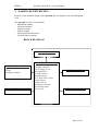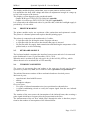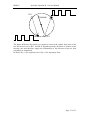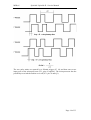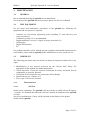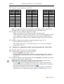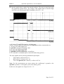
1
Spirolab II Service Manual Service Manual Rev. 0 Prepared by Arne Langenkamp 06/04/01 Date Approved by Paolo Sacco Boschetti 06/04/01 Date MIR srl Spirolab / Spirolab II - Service Manual 1. INTRODUCTION 1.1. 1.1.1. INTRODUCTORY REMARKS General Aspects The spirometers from the product group MIR 010 are marketed under the labels spirolab and spirolab II. The main difference between the 2 models spirolab and spirolab II is principally an LCD display in colour in the model spirolab II while the model spirolab has a black and white LCD display. From here onwards for the sake of brevity, where not indicated differently with the wording spirolab we refer to all models of the product group. This manual has been written for the technicians involved in the service of the spirolab. Service can be carried out by the service organization of the manufacturer or by any other technician authorized by MIR srl. The manufacturer will not be held responsible for the results of maintenance or repairs by unauthorized persons. 1.1.2. Safety Aspects Safe execution of the procedures in this manual requires technical experience and general knowledge of safety precautions. ! Before you start any operation on the unit, you must have first read both the User’s and this Service manual. Warnings, Cautions and Notes are used throughout this manual to bring special matters to the immediate attention of the reader. The Warning concerns danger to the safety of the technician or user. The Caution draws attention to an action which may damage the equipment. The Note points out a statement deserving more emphasis than the general text, but which does not deserve a Warning or Caution. Warning: In order to prevent unforeseen incidents, keep away from sensitive electronical devices. Inside the spirolab there are high voltages but at very low currents, so these represent no danger for persons with experience and with a general knowledge of safety precautions. In exceptional cases these high voltage may cause interference with other electronic devices. The sequence of steps in a procedure may also be important from the point of view of personal safety and prevention of damage, therefore never change the sequence of steps or alter any procedure. Page 2 of 33 MIR srl ! Spirolab / Spirolab II - Service Manual Warning: Batteries may explode if defective or damaged or disposed of in fire. Do not short-circuit the batteries! 1.1.3. Legal Aspects This manual and the information herein are property of MIR srl (Rome, Italy). Copying this manual in whole or in part is strictly forbidden. MIR srl disclaims any responsibility for personal injury and/or damage to equipment caused by: negligence or disregard of a Warning or Caution deviation from any of the prescribed procedures execution of activities which are not prescribed ignorance of the general safety precautions for handling tools and the use of electricity incorrect or unreasonable use - 1.1.4. Environmental Aspects Please dispose properly of any items replaced, following all the local regulations. All components (housing, PCBs, batteries, printer, electronic and disposable para.ts, etc.) must be disposed of according to the relevant local regulations. 1.2. DATA REGISTRATION 1.2.1. Equipment and customer registration / Service file From the point of view of safety and product liability the following data must be registered for each unit: − − − − Equipment data: model and serial number Customer data: date of purchase, name and full address of the customer Service data: log of all service activities Configuration data: the actual configuration of the equipment (hardware and software versions). The distributor (through their dealer and/or service organization, if any) is responsible for maintaining these record and they must be able to provide these data when requested. 1.2.2. Configuration register A configuration file gives the serial numbers and/or batch numbers of main subassemblies and/or important para.ts of each unit. The para.ts listed in a configuration file are defined as registered para.ts. For example para.ts as mainboards, keyboards, battery packs and internal software. Note: MIR srl has the original configuration file of each unit sold. Any possible changes in the original configuration of the supplied units must be filed and the distributor must be able to provide this data. These changes can simply be stored in Page 3 of 33 MIR srl Spirolab / Spirolab II - Service Manual the service file of the specific unit. Para.t, serial or batch number(s) of the new para.t must be documented. 1.2.3. Product documentation The documentation set for the spirolab includes a User’s Manual. The User’s Manual is a recommended item for all service engineers. Ordering data: - 980060 - 980070 1.2.4. User’s Manual Service manual Installation Warning: The mains connection must comply with the national requirements regarding medical facilities. Before connecting this appara.atus to the mains supply, check that the mains voltage and frequency stated on the type plate of the battery charger correspond to that of the local mains supply. The 220-240V model is intended for nominal mains voltages of 220, 230 or 240 volt. The 115V model is intended for nominal mains voltages of 110 or 120 volt. 1.2.5. Technical modifications This publication could include technical inaccuracies or typographical errors. Changes are periodically made to the information herein; these changes will be published as Service Info in appendix B of this Service Manual. Note: Some functions described in this manual may not be activated in the present software or hardware-version. For detailed information, please refer to the User’s Manual. 1.2.6. Product evaluation In order continuously to improve the quality of our products, MIR srl requests that the service organizations should report any device problem which may be discovered. When the same problem regularly occurs or when a safety problems occur, MIR srl would like you to send us a product complaint report. The report must contain the name, the type of the product, a detailed description of the problem, the frequency of the same problems, quantity of sold equipment and your solution to the problem (if any). Page 4 of 33 MIR srl 1.2.7. Spirolab / Spirolab II - Service Manual Additional Information Please do not hesitate to contact us if you require additional information. MIR srl Via del Maggiolino, 125 00155 Rome Italy Tel.: +39/06/2275 4777 Fax.: +39/06/2275 4785 Email: [email protected] Page 5 of 33 MIR srl 1.3. Spirolab / Spirolab II - Service Manual GENERAL The spirolab is an “open circuit system” for the measurement of inspiratory and expiratory lung function para.ameters. It is suitable for basic lung function analysis of the mechanical respiratory tract para.ameters. Three different respiratory manoeuvres can be performed: the forced vital capacity test (FVC), the slow Vital Capacity test (VC/IVC) and the Maximum Volontary Ventilation test (MVV). The spirolab has been designed and manufactured to ensure the highest level of safety and the unit fully complies with the stringent international IEC 601-1 and IEC 601-1-2 standards. 1.3.1. 1.3.1.1. Technical Data Battery charger Battery charger supply : 115 VAC, 220-240 VAC Permissible mains voltage var. : ±15% (115 V), ± 10% (220-240 V) Mains frequency : 50 – 60 Hz Max. current : 1 A at 12 V 1.3.1.2. Spirolab unit Max. current inside the unit : 3,2 A (during printing) Internal fuses : T 2 A (FUS1) SMD (battery charge controller) : T 4 A (FUS2) SMD (main fuse) Internal batteries : Ni-MH for main power supply (6x1,2 V), 4 Ah : Lithium for data backup (1x3,6 V), 370 mAh Approval : CE 0476 EC mark for Medical Devices Dimensions : 310×200×65mm Weight : 1,9 kg (including battery pack) Volume range : 10 L, BTPS Flow range : ± 16 L/s, BTPS Volume accuracy : ± 3% or 50 mL Flow accuracy : ± 5% or 200 mL/s Dynamic resistance at 12 L/s : < 0,8 cmH2O/L/s Type of electrical protection: Class 2 appara.atus Level of protection against direct or indirect contact: Category BF appara.atus Level of water ingress protection: Common appara.atus Level of assurance of use in the presence of an anaesthetic mix flammable with air or oxygen or protoxide of nitrogen : Appara.atus not suitable Conditions of use : Appara.atus for repeated use Storage conditions : Temperature: MIN 0 °C, MAX +40 °C Humidity: MIN 10% RH; MAX 95%RH Operating conditions : Temperature: MIN +10 °C, MAX +40 °C; Humidity: MIN 10% RH; MAX 95%RH Page 6 of 33 MIR srl 1.4. - Spirolab / Spirolab II - Service Manual STANDARDS APPLIED According to rule 10 of the European directive 93/42/CEE the device is classified as Class IIa EN 60601-1 Electronic medical appara.atus. Para.t 1: General safety standards EN 60601-1-1 Electronic Medical appara.atus. Para.t 1: General safety standards 1. Collateral standard: Safety requirements for medical electronic systems EN 60601-1-2 Electronic medical appara.atus. Para.t 1: General safety standards 2. Collateral standard: Electromagnetic compatibility – Requirements and tests EN 60601-1-4 Electronic medical appara.atus. Para.t 1: General safety standards 4. Collateral standards: Programmable medical electronic systems ERS: The European Respiratory Journal - Standardised Lung Function Testing – Volume 6 Supplement 16, March 1993 ATS: Standardisation of Spirometry - 1987 Update – American Review of Respiratory Disease 136:pp.1285-1298,1987 ATS: Standardisation of Spirometry - 1994 Update – American Review of Crit. Care 152: pp.1107-1136,1995 Page 7 of 33 MIR srl Spirolab / Spirolab II - Service Manual 2. HARDWARE DESCRIPTION Because of the modular design of the spirolab, the description is on a block diagram level. The spirolab consists of six modules: – Mainboard module – Keyboard module – Display module – Printer module – External turbine flowmeter – External battery charger BLOCK DIAGRAM DISPLAY MODULE TURBINE FLOWMETER Optoelectronic head Turbine Mouthpiece adaptor 12 V-BATTERY CHARGER MAINBOARD MODULE Batteries Charging controller Power supply circuit Microcontroller FLASH memory SRAM memory RTC (Real Time Clock) Printer drivers Display drivers Measuring controller Room temp.sensor RS 232-port PRINTER MODULE KEYBOARD MODULE Page 8 of 33 MIR srl 2.1. 2.2. Spirolab / Spirolab II - Service Manual MAINBOARD MODULE The mainboard module translates the input signal from the turbine flowmeter into spirometry values and compara.es them with the predicted values calculated with the para.ameters age, sex, height, weight and ethnic group. Test results are displayed on a LCD and can be printed on paper. Spirometry test data are stored into memory and are available for later use. The mainboard module includes: - Battery pack (6x1.2V NiMH) for device supply - Lithium battery 3.6V for data backup (SRAM and RTC) - Charging controller for battery pack - DC power supply controlling circuit - Microcontroller, including EEPROM with “boot” program - FLASH memory with “boot” and application software - SRAM memory with device configuration and spirometry data - RTC real time clock - Thermal Printer driver - Graphic LCD driver - Measuring controller for flow, volume and ambient temperature - Ambient temperature sensor (to enable conversion from ATP to BTPS conditions). - Serial RS 232 bidirectional communication port with optoisolation (4 KV) for connection to a PC, external printer, modem etc. 2.2.1. Jumpers On the mainboard are four jumpers, the position of these jumpers is of crucial importance for the correct functioning of the spirolab. SJ1 connects the Lithium backup battery with the mainboard. Removal will cause a loss of all data, both configuration and test data. SJ2 connects the NiMH-battery with the mainboard. If this jumper is removed the unit is disconnected from the battery power supply. JP1 enables you, by setting a jumper, to program the EEPROM inside the microprocessor via the serial RS232 port JP2 enables you to switch between three modes to terminate the charging process. These are further explained in the next para.agraph. Only in the case of a replacement procedure then removal of all jumpers is recommended to avoid unforeseen damage to the mainboard and/or to components. 2.2.2. Charging controller for battery pack The charging controlling circuit used in the the spirolab ensures a fast charge and optimum condition of the battery pack providing that the battery temperature and voltage are within the preset limits. Temperature, voltage and time are all monitored throughout the fast charge process. Page 9 of 33 MIR srl Spirolab / Spirolab II - Service Manual The charging process itself is automatically initiated in two situations: 1. After connecting the battery charger to the unit 2. When the unit is switched on, the battery charger is connected and the voltage level of the battery is below a preset limit. In this situation the LCD indicates the low battery status with two red lines. The fast charging process is terminated by any of the following: - Battery voltage out of range (Maximum/Minimum) Battery temperature out of range (Maximum/Minimum) Maximum charging time (timeout = 5h:30min) Termination according to the charging mode, chosen by jumper JP2. Charging termination modes: 1. Temperature Arise Detection (∆T/∆t), JP2 jumper in the default position as indicated on the attached drawing. The battery temperature increases more quickly when the battery is fully charged. If the speed of temperature increase inside the battery pack exceeds a certain value then the charging process is terminated. The charging controller (IC15) samples the thermistor voltage (NTC) every 34 sec., and compare it to the value measured two samples earlier. If the voltage has fallen 16mV ± 4mV or more, the fast charge is terminated. 2. Peak Voltage Detection (PVD), JP2 jumper in the other possible position: The battery’s voltage decreases slightly when it is fully charged. In this chargingmodes, the microcontroller checks the battery voltage and terminates the charging process in the event that the voltage on the battery pack decreases by more than the preset limit, that limit is configured by the position of the jumper: In this mode, the battery’s voltage is the criteria for terminating the charging process. If the voltage decreases by 36mV ± 4mV in 34 seconds this means that the battery is fully charged, and the controller then terminates the charging process. 3. Decrease Voltage Detection (-∆V), no JP2 jumper. This mode is correspondent to the PVD-mode, but at higher sensibility, because the charging process ends at a voltage decrease of 18mV ± 2mV in 34 seconds. ! Caution: In case of needing high power while charging (i.e. when printing), the battery’s voltage decreases. In this case using the modes Peak voltage Detection or -∆V the charging process will be terminated, although the battery is not fully charged. The factory setting is designed for the ∆T/∆t Termination mode and is not to be changed to avoid the above-mentioned problems! Charging phases: 1. After connecting the battery charger to the unit, the red LED (CHARGE_LED) starts flashing for few seconds. In this period, the battery is charged in pulses at a low frequency and the battery’s response is monitored. If the red LED continues to flash this shows that the battery’s temperature is out of range or the battery voltage is too low. In this case, the controller enters the charge pending state and waits for both conditions to fall (temperature) or rise (voltage) within their allowed limits. There is no time limit on the charge pending state; the charger remains in this state for as long as the voltage or temperature conditions are outside Page 10 of 33 MIR srl Spirolab / Spirolab II - Service Manual of the allowed limits. If the voltage is too high, the controller goes to the battery absent state and waits until a new charge cycle is started. 2. If everything is in order (battery temperature, temperature rising, battery voltage etc.) then the fast charging process starts, the red LED lights continuously. In the following 10 minutes, the battery is charged at a lower rate to initialize slowly the chemical reaction inside the battery pack. After about 10 minutes, high-frequent pulses at the full current rate of 1A charge the battery. 3. At the end of the regular charging process, the green LED (DONE_LED) lights continuously. Now it can be assumed that the battery is full charged. 4. If after completing the charging process the battery charger is still connected, a socalled Pulse-Trickle-Function is activated that gives a very low charge to compensate the self-discharging of the battery while it is idle connected to the charger. 2.2.3. Room temperature sensor Transducer of temperature/voltage (IC 12) NATIONAL LM 35 to measure the ambient (room) temperature to enable the calculation of the BTPS conversion factor. The output signal, amplified through an operational amplifier (IC 13, 100 mV/°C) is connected to one of the A/D channels of the microprocessor (IC1, line ROOM_T, pin 35). 2.2.4. RS 232 communication port Bidirectional serial port, controlled by the microprocessor via its serial port. Towards the PC the port has 9 lines, configured according to the EIA RS232 Standard: Pin 1. 2. 3. 4. 5. 6. 7. 8. 9. Description Received Line Detector Receive Data Transmit Data Data Terminal Ready Signal Ground (NC) Request To Send (NC) (NC) RX TX DTR GND RTS NC = Not connected The voltage of the signals according to this standard is in the range of +3 to +12 V for High Level (true value) and –3 to –12 V for Low Level (false value). Note: Because spirolab is isolated from the connected device by optocouplers, there are two electrical grounds. For internal measurements (before the signal reaches the optocouplers), there is an internal ground i.e. the negative pole of the battery pack. For measurements between the optocouplers and the connected device, you must use the external ground, which is different (i.e. pin 5 of CN1). 2.3. DISPLAY MODULE Page 11 of 33 MIR srl Spirolab / Spirolab II - Service Manual The display module displays patient data, user set para.ameters and test results. It is attached to the body with a hinge and allows an adjustment in angle in a range up to 160° with respect to the chassis. The display-version depends on the purchased model: Graphic B/W type FSTN LCD 320×240 pixel (spirolab) Graphic 16-colour type FSTN LCD 320×240 pixel (spirolab II) It is connected to the mainboard with a 16-pin flat-cable, while the backlight supply is provided by a 2-wire-cable. 2.4. PRINTER MODULE The printer module carries out a printout of the patient data and spirometric results. The printer is a thermal printer and requires thermal printing paper. The printer is connected to the mainboard via 3 cables: - a 4-pin flat-cable for driving the motor for paper advance - a 4-pin flat-cable for the sensor, that checks that paper is inserted - 28-pin flat-cable for supply, data transmission and checking the temperature of the printer head, to avoid overheating 2.5. KEYBOARD MODULE The keyboard module constitutes the interface between user and unit. It is connected to the mainboard via two 15-pin flat-cables (CN 8, CN 9). When the unit is switched off, the only active key is the red ON_OFF key, which allows the unit to be switched ON or OFF manually. 2.6. TURBINE FLOWMETER The sensor for measuring flow and volume is the same one already used in other spirometers produced by MIR (Series MIR 001 Mod. spirobank and spirobank G). The turbine flowmeter consists of three mechanical and two electrical para.ts: Mechanical parts: - optoelectronic head with IR-sensor - turbine - mouthpiece adaptor Electrical parts: - Two pairs of infrared transmitters/receivers positioned as shown below. - A signal conditioning circuit to rectify the output signal from the two infrared light receivers. The rotation of the rotor causes the interruption of the infrared beam, thus creating a pulse signal which has a frequency directly proportional to the flow. The measurement of the air flow which passes through the tube is therefore proportional to the number of interruptions of the infrared beam. Page 12 of 33 MIR srl Spirolab / Spirolab II - Service Manual TX2 TURBINE RX2 RX1 TX1 The phase difference ∆ϕ (positive or negative) between the signals from each of the two infrared receivers (IR 1 and IR 2) depends upon the direction of rotation of the moving rotor and therefore supply the information of the direction of the air flow (expiration or inspiration). In detail, ∆ϕ > 0 for expiratory flow, ∆ϕ < 0 for inspiratory flow. Page 13 of 33 MIR srl Spirolab / Spirolab II - Service Manual The two pulse trains are squared by a Schmitt trigger (IC 14) and then sent to two input ports of the microprocessor (IC1, pins 83 and 84). The microprocessor has the possibility to switch the turbine on or off (IC1 pin 78 and Q1). Page 14 of 33 MIR srl Spirolab / Spirolab II - Service Manual 3. MAINTENANCE 3.1. GENERAL We recommend checking the spirolab on an annual basis. For cleaning of the spirolab and the accessories please see the User’s Manual. 3.2. TEST EQUIPMENT For the repair and maintenance procedures of the spirolab the following test equipment and accessoires are required: Complete set of precision engineering tools (including 2.5 mm allen key and cross-screwdriver) Calibration syringe (3L is recommended) Digital multimeter, at least 3½ digits, accuracy better than 1%. Oscilloscope Digital Thermometer PC - If a problem cannot be solved with the present equipment and suitable instruments are not available, please send the spirolab to the manufacturer to carry out the service. 3.3. CHECKLIST The following procedures must be carried out during an inspection and/or after every repair: • • • • • Modifications, if any, must be noted on the the “Service Info” sheets. See appendix B of this manual for further information. Visual inspection. Check the electrical connection for safety and check that all components are properly fastened. Check that all accessories do not present any visible damage. Functional test (see. Chapter 4.3) File a copy of all service activities. 3.3.1. 3.3.1.1. Functional test Self Test Switch on the equipment. The spirolab will carry out the so-called self-test for approx 3 seconds. It is assumed that when the self-test is passed all functions of the spirolab are okay. Any severe malfunction (if any) will be reported on the display or the printer. Switch off the spirolab. Page 15 of 33 MIR srl 3.3.1.2. Spirolab / Spirolab II - Service Manual Software version The software version is indicated in the upper line of the main data screen and on every printout. 3.3.1.3. Hardware control All these points must be controlled before doing any measuring test or replacement on the unit. 1. The housing does not show any severe damages like scratches, splits or breakages, that could endanger a secure use. 2. All 5 rubber feet on the chassis are present and not damaged. 3. All pixels on the display are visible and there are no scratches on the display. 4. Time and date are correct. 5. Pressing any key (except the ON/OFF-Key and the keys to adjust the display) causes a short beep. 6. The PCB is firmly attached to the chassis by 8 screws. 7. The printer is firmly attached to the chassis by 4 screws. 8. The keyboard is firmly attached to the case by 10 screws (9 metal, 1 Nylon) 9. The battery pack is firmly attached to the PCB. 10. The two fuses FUS1 and FUS2 are not blown. 11. The soldered points of the battery pack are without any damages and provide a safe connection. 12. The 3 LEDs are firmly soldered to the keyboard PCB. 13. The room temperature sensor is near the housing. 14. The JP2 jumper (battery charging mode) is in the default position. 15. The protection plastic angle for IC12 in the angle is present and not damaged. 3.4. 3.4.1. REPLACEMENT PROCEDURES General When handling sensitive static devices such as the mainboard of the spirolab the following precautions should be observed: - Persons should be earthed by means of a wrist strap. - Ground all electrical equipment, workbench etc. ! ! Caution: Removing SJ1 jumper will cause a loss of all data. After having removed one or more of the jumpers make sure to replace them properly when the repair is finished. Caution: Even if the unit is switched off the internal batteries are active and are supplying current so there are still voltages available, that can be easily short-circuited. To avoid unforeseen damaging through voltage, removal of all jumpers is recommended. Before removing the jumpers remember that removing the SJ1 jumper will cause a loss of all test data in memory. Also make sure that you do have left any tools inside and all screws including their washers are again fixed in the original place. Page 16 of 33 MIR srl Spirolab / Spirolab II - Service Manual Note: Where not otherwise indicated, the reinstallation of a part is in reverse order of the removal procedure. After every repair a functional test must be performed. 3.4.2. Cover Remove: Switch off the unit and close the display. Disconnect the battery charger cable from the device. Disconnect the turbine flowmeter. Turn the spirolab upsidedown. Remove the screws with a 2.5mm Allen key. Turn the spirolab to its original position. ! Caution: Be careful not to damage the cables while opening the spirolab. Carefully lift the cover on the backside about 50 mm from the chassis. Then pull the cover about 50 mm towards you. In this way you create just enough space between the chassis and the cover to remove the cables. Disconnect the display backlight supply (CN 3) and the display cable (CN 4). Note: The keyboard cables (CN 8, CN 9) are not disconnectable. Turn the cover over the front edge, so that cover is lying next to the chassis. 3.4.3. ! Printer Warning: The printer motor could be very hot! Do not touch! Removal: See para. 3.4.2 for removal of the cover. Remove the paper out of the printer. Remove the screws which fix the printer to the chassis. Disconnect the wiring which connects the printer to the mainboard from connectors CNB1, CNC and CNA1. Remove the printer. 3.4.4. 3.4.4.1. PCBs and components Keyboard Removal: See para. 3.4.2 for removal of the cover. Remove the screws which attach the keyboard to the cover. Disconnect the mainboard with a soldering iron and take off the keyboard. 3.4.4.2. Complete PCB-unit (mainboard + keyboard) Removal: See para. 3.4.2 for removal of the cover. See para. 3.4.3 for removal of the printer. Remove the screws which attach the PCB to the chassis. Remove the screws which attach the keyboard to the cover. Lift it up on the battery side and after having reached an almost nearby vertical position, remove it. Page 17 of 33 MIR srl 3.4.4.3. ! Spirolab / Spirolab II - Service Manual Components Caution: If any solderings (especially on SMD-para.ts) are to be made, make sure, that your tools are suitable for such precision work. Removal: See para. 3.4.2 for removal of the cover. See para. 3.4.3 for removal of the printer. Remove the screws, which attach the PCB to the chassis. Remove the screws, which attach the keyboard to the cover. Lifting it on the battery’s side and after having reached a nearby vertical position, remove it. 3.4.5. Membrane keyboard Removal: See para. 3.4.2 for removal of the cover. Remove the screws which attach the keyboard to the cover. Lift the keyboard and remove the membrane keyboard. 3.4.6. Display Warning: In order to prevent unforeseen incidents, keep away from sensitive electronical devices. Feeding the display high voltages are present (max. 450 V), but at very low currents (max. 6 mA) so these represent no danger for healthy persons with experience and general knowledge of safety precautions. In exceptional cases these high voltage may interfere with sensitive electronical devices. Removal: See para. 3.4.2 for removal of the cover. Lift with moderate force the display first on the side where the supplementary cables leave the display’s housing, then at the other side. 3.4.7. Battery pack The instrument is powered by rechargeable batteries (6 elements Ni-MH 1,2 V, 4000 mAh). A 3,7 V lithium battery maintains the backup of the SRAM and RTC. ! Warning: The batteries may explode if defective or damaged or disposed of in fire. Do not short-circuit the batteries! Removal: See para. 3.4.2 for removal of the cover. See para. 3.4.4.2 for removal of the PCB. Disconnect the wiring which connects the battery to the mainboard from connectors CN6. Turn the mainboard over, detach the battery and remove it. Note: Always replace the battery with the same type of battery. The internal batteries must be disposed off according to the local regulations. 3.4.8. Optoelectronic head The optoelectronic head is a complete assembly. Inside are no serviceable items. When defective, the complete head must be replaced. Page 18 of 33 MIR srl 3.4.9. Spirolab / Spirolab II - Service Manual Turbine Removal: Pull the turbine/mouthpiece adaptor out of the turbine flowmeter. Pull the turbine out of the mouthpiece adaptor. 3.5. 3.5.1. ! ADJUSTMENT PROCEDURES Spirolab unit Note: The spirolab turbine measurement system is calibrated in the factory and does not require any adjustments or calibrations. 3.5.2. Turbine flowmeter For proper working the flowmeter must be kept clean. For information about cleaning the flowmeter see the User’s Manual. Calibrating the flowmeter is only possible by the “turbine calibration” function of the spirolab. Please refer to the User’s Manual. Page 19 of 33 MIR srl Spirolab / Spirolab II - Service Manual 4. SPARE PARTS This chapter deals with placing orders for spare parts (see para. 6.1) as well as the listing of actual spare parts (appendix A, spare parts list). 4.1. ORDERING Spare parts can only be ordered if the following data is supplied: - Part number - Description - Quantity - Shipping details (Incoterms) The required data is mentioned in appendix A. For the current parts programme please refer to the spare parts price list which is published every year. MIR only supplies parts mentioned in appendix A. Standard parts such as screws, nuts, cleaning agents and so on are not supplied by MIR, these parts must be purchased locally. Send your order to your contact person at the sales department of MIR. After receipt of an order you will receive a confirmation. Our minimum order value is 250 Euro. Always check the ordering data. 4.1.1. Ordering PCB's Printed circuit boards are only obtainable as spare part in their latest version. Consult the technical documentation for instructions of how to modify the latest version of the PCB for use in older versions of the equipment. 4.1.2. Warranty claims Warranty claims must be provided with the MIR invoice number, the type of products and serial number of the equipment in question. The defective item must be returned back to MIR. The customer is responsible for the transportation and for all transport and customs charges for the delivery of the goods both to and from the service centre. 4.2. RETURN SHIPMENTS - Any instrument or accessory returned must be accompanied by a clear and detailed explanation of the defect or problem found. - If units are to be returned to MIR then a written or verbal permission (RAN Return Authorization Number) must be received before any instrument is returned to MIR. - The unit must be returned in its original packaging. - MIR reserves the right to modify the instrument if required, and a description of any modification made will be sent along with the returned goods. Page 20 of 33 MIR srl ! Spirolab / Spirolab II - Service Manual Note: Any instrument of accessory returned must be accompanied by a clear and detailed explanation of the defect or problem found. Page 21 of 33 MIR srl Spirolab / Spirolab II - Service Manual 5. TROUBLESHOOTING Note: Where not indicated, voltages are measured versus the ground (i.e. the negative pole of the battery pack). Note: Where not indicated, voltages are measured while the unit is switched on. Note: Where not indicated, the values to be measured can vary by about 2%. Warning: Be careful not to short-circuit any contacts while measuring voltages. Batteries may explode if defective or damaged or disposed of in fire. Do not short-circuit the batteries! 5.1. THE DEVICE DOES NOT SWITCH ON Check the voltage of the internal battery pack. – Open the spirolab (refer to para. 3.4.2) – Measure the voltage between the two poles of the battery pack, it must be between 6 V (low battery) and 8 V (full charged). Check the internal power supply. – The voltage on pin 3 of IC 29 must be 5 V. – The voltage on pin 3 of CN 9 for the ON_LED must be approx. 1.8 V. If the battery charger is connected: Check the battery charger: – Make sure that the main power supply’s jack is correctly attached to the plug. – Check the cable for visible damage. – The voltage between inner and outer part of the jack must be 12 V. Check the internal power supply: – Open the spirolab (refer to para. 3.4.2). – Measure the voltage behind the fuse (FUS1) on the point indicated on the attached drawing. It must be approximately 12 V. Check the voltage on R1. It must be 5 V. Check the voltage on pins 2 and 3 of IC 24. They must be 0 V. Check the voltage on L6. It must be 5 V. 5.2. THE LCD DOES NOT DISPLAY Warning: In order to prevent unforeseen incidents keep away from sensitive electronical devices. Feeding the display high voltage is present (max. 450 V) but at very low current (max. 6 mA), so that this represents no danger for healthy persons with experience and general knowledge of safety precautions. In exceptional cases these high voltage may interfere with sensitive electronical devices. Check the data connection – Open the spirolab (refer to para. 3.4.2). – Check the flat cable CN 4. – Check if the connector CN 4 is closed. – Check if the adhesive protection on CN 4 is attached. Check the mainboard’s function – Open the spirolab (refer to para. 3.4.2) – Switch on the device. Page 22 of 33 MIR srl Spirolab / Spirolab II - Service Manual – Check the voltage between pin 1 and 4 of CN 3. This requires an oscilloscope. The amplitude peak to peak must be approximately 400 V at a frequency of approx. 60 kHz. Check the voltage on pin 7 of CN 4. This must be between 20 and 24 V, depending on the regulation of the display contrast. Check the voltage on pin 7 (RESET signal) of IC 34. It must be 5 V. Check the backup power supply (lithium battery): – Measure the voltage on pin 32 of IC 6. When the unit is switched off it must be 3.6 V equal to the voltage of the lithium battery BT1. When the unit is switched on it must be 5 V. – Check the voltage on pin 3 of IC 22. It must be 3.3 V. Check the voltage on pin 5 of CN 4. It must be 5 V. 5.3. THE BATTERY CHARGING IS NOT WORKING CORRECTLY Check the battery charger – Make sure that the main power supply’s jack is correctly attached to the plug. – Check the cable for visible damage. – The voltage between the inner and outer parts of the jack must be 12 V. Check the internal power supply – Open the spirolab (refer to para. 3.4.2). – Measure the voltage behind the fuse (FUS1) on the point indicated on the attached drawing. It must be approximately 12 V. Check the thermistor – Open the spirolab (refer to para. 3.4.2) – Remove the thermistor cable from connector CN6. The resistance of the thermistor must be about 10 kΩ at room temperature (23°). – Replace the thermistor cable firmly to the connector CN 6. Check the red LED (CHARGE_LED). – Open the spirolab (refer to para. 3.4.2) – Check the voltage on pin 4 of CN 9 (Flexstrip). It must be 1.8 V. 5.4. THE LITHIUM BACKUP BATTERY INDICATES DISCHARGED Check the voltage of the lithium battery – Open the spirolab (refer to para. 3.4.2) – Check the voltage of the battery BT1 at SJ1 jumper, it must be 3.6 V. ! Warning: Batteries may explode if defective or damaged or disposed of in fire. Do not short-circuit the batteries! ! Caution: Removing the jumper at SJ 1 or the battery will cause a loss of ALL data in memory! Note: Batteries must be disposed off properly, according to the local regulations. 5.5. THE PRINTER DOES NOT PRINT Make sure that suitable convenient thermal paper is inserted (112 mm width). Check the printer connections – Open the spirolab (refer to para. 3.4.2) – Remove the 4 screws that attach the printer to the housing. – All 3 flat cables must be firmly attached to CNA, CNB, CNC. Page 23 of 33 MIR srl Spirolab / Spirolab II - Service Manual Check the voltage on R 77. – Open the spirolab (refer to para. 3.4.2) – Remove the printer (refer to para. 3.4.3) – Check the voltage on R 77 during printing. It must be 5 V. Check the voltage on the paper drive motor. – Open the spirolab (refer to para. 3.4.2) – Remove the printer (refer to para. 3.4.3) – Check the voltages on pins 2 and 9 of IC 9 and IC 10 while the printer is printing. They must be approx. 7 V depending on the battery level. 5.6. THE PRINTER MAKES NOISES The printer is not firmly screwed to the body. – Open the spirolab (refer to para. 3.4.2) – Tighten the 4 screws using moderate force. 5.7. THE DEVICE DOES NOT MEASURE AT ALL Check if any obstacle is blocking the free rotation of the turbine Check the cable for any visible damage. For information about maintenance cleaning and sterilization please refer to the relevant paragraph in the User’s Manual. 5.8. THE DEVICE DOES NOT MEASURE CORRECTLY Check if any obstacle is disturbing the free rotation of the turbine. For information about maintenance cleaning and sterilization please refer to the relevant paragraph in the User’s Manual. Check the turbine’s power supply – Open the spirolab (refer to para. 3.4.2) – Remove the printer (refer to para. 3.4.3) – Press FVC to activate the turbine’s power supply – Check the voltage on pin 7 of CN2 connector. It must be 5 V. This signal is 0 V when FVC measurement is terminated. Check the turbine’s signal. This requires an oscilloscope. – Open the spirolab (refer to para. 3.4.2) – Picking up the signal before L1 while blowing into the turbine, you see the original pulse signal at approx. 4V (see the picture on the right). – Behind L1, the signal must be more clearly at approx. 4V. On pin 12 of IC 14, you must see this signal inverted and squared at 5 V. – The same procedure is to be made at L2 and pin 10 of IC 14. Page 24 of 33 MIR srl Spirolab / Spirolab II - Service Manual Check the conversion factors for BTPS: Temp. 9°C 10°C 11°C 12°C 13°C 14°C 15°C 16°C 17°C 18°C 19°C BTPS 1.164 1.160 1.155 1.151 1.147 1.142 1.138 1.133 1.129 1.124 1.120 Temp. 20°C 21°C 22°C 23°C 24°C 25°C 26°C 27°C 28°C 29°C 30°C BTPS 1.115 1.111 1.106 1.101 1.097 1.092 1.087 1.082 1.078 1.073 1.068 Temp. 31°C 32°C 33°C 34°C 35°C 36°C 37°C 38°C 39°C 40°C 41°C BTPS 1.063 1.058 1.053 1.048 1.043 1.038 1.033 1.028 1.023 1.018 1.013 Note: The indicated values are calculated for a humidity of 50%. The more the humidity differs, the grater is the deviation of the calculated values. Check the accuracy with the calibration syringe. - Make several tests FVC at different in- and expiration speeds. - Check the measured volume. It may differ ± 3% or 50 ml, depending on which value is bigger (i.e. using a 3000-ml-syringe, the measured valued must be between 2910 and 3090 ml, using a 1000-ml-syringe, between 950 and 1050 ml) Check the voltage on the ambient (room) temperature sensor IC 12 - Open the spirolab (refer to par. 3.4.2) - The voltage on pin 4 of C 13 must be 100 mv/°C (i.e. 2,5 V for an ambient temperature of 25 °C). 5.9. THE DATA COMMUNICATION VIA RS232 DOES NOT FUNCTION ! Check the cable, if there are any visible damages. Check the RTS function for “line power supply” – Open the spirolab (refer to par. 3.4.2) – During the RS232 transmission measure the voltage between pin 7 and pin 5 (ground of the connected device) of CN1. It must be “high level” (between +3 and +12 V). Check data transfer while transmitting data from spirolab on the RS232 port (this requires an oscilloscope with memory) Note: Make sure, that you have connected the oscilloscope’s ground of the connected device (PC, printer, modem etc.) at pin 5 of CN1. – Press the key (PC connection function) to start a process that sends the whole SRAM data via the RS232 port. This process endures about 10 minutes, but can be interrupted at any time by pressing . – Pick up the data stream at pin 2 of CN1. You must see pulses at 9600 baud (9600 bit/sec) at a voltage in the range of RS232 standard (refer to 2.1.1.4). Page 25 of 33 MIR srl Spirolab / Spirolab II - Service Manual Start the application to update the internal software. The process must begin with the signal flow shown below. The voltage of the signals must be between High and Low level following the RS232 standard (refer to 2.1.1.4). A: PC drives TX and DTR signals to a default state A-B: PC transmit 500 bytes continously and spirolab switches automatically on. C: PC drives the DTR signal Low D: spirolab responds transmitting a byte E: PC drives the DTR signal High F: PC drives the DTR signal Low G: spirolab responds transmitting a second byte H: PC transmits a command (byte) to start the flash erasing process. The same signals can be picked up behind the optocoupler: TX of the PC on pin 4 of IC 14 DTR of the PC on pin 2 of IC 14 TX of the spirolab (RX of the PC) on Pin 6 of IC 14 Note: For this measurement you must connect the oscilloscope’s ground to the spirolab’s ground (i.e. the negative pole of the battery pack) In this case, the signals are at logic level 0 / 5 V. Page 26 of 33 MIR srl 5.10. Spirolab / Spirolab II - Service Manual INDEX OF COMPONENTS To simplify component identification they are marked in the attached drawing of the components layout of the Printed Circuit Board (PCB) MIR 009, rev. 3. The revision number of the PCB is indicated on the component side on the lower right, next to the battery pack). Comp.-ID Description......................................................................No. in drawing BT1 CN1 CN2 CN3 CN4 CN6 CN8 CN9 CNA Lithium battery for data retention.........................................................8 RS232 serial communication port.......................................................23 Connector for the optoelectronic turbine head......................................1 Connector for backlight supply of the LCD........................................18 Connector for the display data cable...................................................17 Connector for the thermistor of the battery pack................................13 Flatcable for the keyboard...................................................................35 Flatcable for the keyboard...................................................................34 Connector for supply, data transmission and printer head temperature...................................................................................5 CNB Connector for power supply of the printer motor.................................3 CNC Connector for sensor that checks the paper...........................................7 FUS1 2 A battery charging controller fuse (on the mainboard)....................15 FUS2 4 A mainboard fuse.............................................................................12 IC1 Microcontroller....................................................................................29 IC6 SRAM memory 4 Mbit.......................................................................28 IC9 Driver for the paper’s motor..................................................................2 IC10 Driver for the paper’s motor..................................................................4 IC11 Optocoupler for printer head and motor power supply enable..............6 IC12 Ambient (room) temperature sensor...................................................26 IC13 Operational amplifier for ambient temperature sensor (IC12)............25 IC14 Hex inverter with Schmitt trigger........................................................21 IC 22 Voltage regulator 3.3V output for display controller (IC21)..............31 IC23 I/O decoder for display controller (IC21)...........................................33 IC24 RTC.....................................................................................................19 IC29 Voltage regulator 5V output for device switch on..............................27 IC34 RESET and data retention controller....................................................9 JP1 Jumper selector to program the EEPROM..........................................20 JP2 Jumper for adjusting the battery charging termination mode.............14 L1 Inductor for turbine signal filter..........................................................24 L2 Inductor for turbine signal filter..........................................................22 L6 Inductor for the DC/AC converter of LCD backlight.........................16 NEG. pole Negative pole of the NiMH battery pack............................................30 POS. pole Positive pole of the NiMH battery pack..............................................36 R1 Resistor................................................................................................32 SJ1 Jumper for connecting the battery pack with the unit.........................10 SJ2 Jumper for connecting the Lithium battery with the unit....................11 Page 27 of 33 MIR srl Spirolab / Spirolab II - Service Manual APPENDIX A: SPARE PARTS LIST Product description Product code Model Pack Quantity Axis for paper roll 340832 SL I / SL II 1 Battery pack 6 x 1.2 V, 4 Ah (rechargeable, internal) Lithium battery 3,6 V 972301 SL I / SL II 1 970232 SL I / SL II 1 Battery charger 220V 920665 SL I / SL II 1 Battery charger 110V 920675 SL I / SL II 1 Buzzer BZ 1 560020 SL I / SL II 1 Carrying case (soft) 672685 SL I / SL II 1 Display (black/white) complete with flat connecting cable Display (colour FSTN) complete with flat connecting cable Flat cable to connect display to PCB Fuse F1, 2 A, SMD 0805 660591 SL I 1 660056 SL II 1 450100 SL I / SL II 1 270464 SL I / SL II 1 Fuse F2, 4 A, SMD 0805 270468 SL I / SL II 1 LED orange for PCB keyboard 251900 SL I / SL II 1 LED green for PCB keyboard 251906 SL I / SL II 2 Membrane keyboard 221540 SL II 1 Optoelectronic turbine holder with cable (without turbine flow meter) Paper roll for printer 910012 SL II 1 910350 SL II 20 PCB keyboard without mainboard 450055 SL I / SL II 1 PCB mainboard without LCD display and without printer Plastic case (ABS) blue, complete including screws RS232 cable (spirolab to PC) 001040 SL I / SL II 1 301040 SL I / SL II 1 671492 SL I / SL II 1 RS232 port CN 1 124556 SL I / SL II 1 Rubber feet, set of 4 301301 SL II 1 set Serial-Parallel printer converter 910110 SL I / SL II 1 Thermal printer 660075 SL I / SL II 1 Transformer T1 350001 SL I / SL II 1 Turbine flow meter 910000 SL I / SL II 1 Page 28 of 33 MIR srl Spirolab / Spirolab II - Service Manual APPENDIX B: SERVICE INFO'S (Product Change Notes) General The technical information in the service manuals of MIR srl is up to date at the date of issue. Necessary additional information (of any kind) will be provided in the following way: - as supplements to the manual, or as revised editions (chapters) of the manual, or as Service Info (product change notes). When a supplement or a revision is made to the manual, a "document history file" is added to this chapter. This file will give information about the date of issue of supplements or revisions. Page 29 of 33 MIR srl Spirolab / Spirolab II - Service Manual REVISION HISTORY First edition: Rev. 1 June 2001 Revision: Date of issue: Revisions: Chapter: page Page 30 of 33 MIR srl Spirolab / Spirolab II - Service Manual Index 1. INTRODUCTION 2 1.1. INTRODUCTORY REMARKS 2 1.1.1.General Aspects............................................................................................................................2 1.1.2.Safety Aspects..............................................................................................................................2 1.1.3.Legal Aspects...............................................................................................................................3 1.1.4.Environmental Aspects.................................................................................................................3 1.2. DATA REGISTRATION 3 1.2.1. Equipment and customer registration / Service file 3 1.2.2. Configuration register 3 1.2.3. Product documentation 4 1.2.4. Installation 4 1.2.5. Technical modifications 4 1.2.6. Product evaluation 4 1.2.7. Additional Information 5 1.3. GENERAL 6 1.3.1. Technical Data 6 1.3.1.1. Battery charger 6 1.3.1.2. Spirolab unit 6 1.4. Standards Applied 7 2. HARDWARE DESCRIPTION 8 BLOCK DIAGRAM 8 2.2. MAINBOARD MODULE 9 2.2.1. Jumpers 9 2.2.2. Charging controller for battery pack 9 2.2.3. Room temperature sensor 11 2.2.4. RS 232 communication port 11 2.3. Display module 11 2.4. Printer module 12 2.5. Keyboard module 12 2.6. Turbine flowmeter 12 3. MAINTENANCE 15 3.1. GENERAL 15 3.2. TEST EQUIPMENT 15 3.3. CHECKLIST 15 3.3.1. Functional test 15 3.3.1.1. Self Test 15 3.3.1.2. Software version 16 3.3.1.3. Hardware control 16 Page 31 of 33 MIR srl Spirolab / Spirolab II - Service Manual 3.4. REPLACEMENT PROCEDURES 16 3.4.1. General 16 3.4.2. Cover 17 3.4.3. Printer 17 3.4.4. PCBs and components 17 3.4.4.1. Keyboard 17 3.4.4.2. Complete PCB-unit (mainboard + keyboard) 17 3.4.4.3. Components 18 3.4.5. Membrane keyboard 18 3.4.6. Display 18 3.4.7. Battery pack 18 3.4.8. Optoelectronic head 18 3.4.9. Turbine 19 3.5. ADJUSTMENT PROCEDURES 19 3.5.1. Spirolab unit 19 3.5.2. Turbine flowmeter 19 4. SPARE PARTS 20 4.1. ORDERING 20 4.1.1. Ordering PCB's 20 4.1.2. Warranty claims 20 4.2. Return shipments 20 5. TROUBLESHOOTING 22 5.1. The device does not switch on 22 5.2. The LCD does not display 22 5.3. The battery charging is not working correctly 23 5.4. The lithium backup battery indicates discharged 23 5.5. The printer does not print 23 5.6. The printer makes noises 24 5.7. The device does not measure at all 24 5.8. The device does not measure correctly 24 5.9. The data communication via RS232 does not function 25 5.10. Index of components 27 APPENDIX A: SPARE PARTS LIST 28 APPENDIX B: SERVICE INFO'S (Product Change Notes) 29 REVISION HISTORY 30 COMPONENT LAYOUT 33 Page 32 of 33 15 5 18 19 20 21 22 23 24 25 26 27 3 2 1 14 17 4 PCB MIR 009, Rev. 3 Component Layout 16 13 12 11 10 1 2 3 4 5 6 7 8 9 Rev. 3 Page 33 of 33 36 35 34 33 32 31 30 29 28