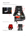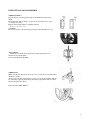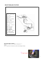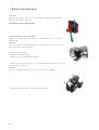
1
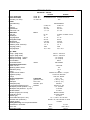
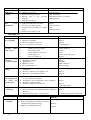
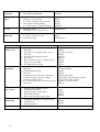
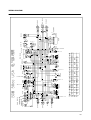
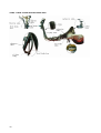
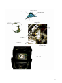
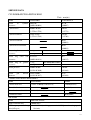
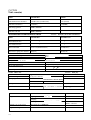
SERVICE MANUAL
FOCUS - 25/30/45 km/t
MATRIX - 25/30/45 km/t
CARL ANDERSEN MOTORCYKLER A/S
Niels Bohrs Vej 15, Stilling
Postboks 680
DK-8660 Skanderborg
Telefon. 8694 6177
Telefax. 8694 4447
www.ca-mc.dk
email: [email protected]
Focus 30/45 km/t
Matrix-30/45 km/t
VIN kode (1-3 ciffer)
TEKNISK DATA
01-05-2006
Værksteds - manual
30 km/t
45 km/t
Godk. Nr.:
e3*2002/24*274*02 e3*2002*/24*274*02
e3*2002/24*274*02 e3*2002*/24*274*02
Godk. Nr.:
TSY
17 cifre i alt
Motor:
Type/mærkning
Type
Volumen
Cylinderdiam.
Effekt i kW / HP
Karburator:
Type mrk.
Hoveddyse
Tomgangsdyse
Gasspjælds højde
Nåleposition
Svømmer højde
Luftskrue (omdr. fra bund)
Tomgang (omdr.)
Tomgangsdyse
2-Takt, AC
49,2 cc
40,0 mm
1,1 / 1,5
KW1E40QMB-4
2-Takt, AC
49,2 cc
40,0 mm
2,1 / 2,9
Mikuni
Hjul / Dæk:
Forhjul (fælg / dæk)
Baghjul (fælg / dæk)
Dæktryk foran/bag >100 kg
Dæktryk foran/bag =MAX
Bremsevæske Transmissionsolie 100ml
Elektriske komponenter:
Batteri 12V-5A
Opladning batteri v/max.
Ladeeffekt (Amp.)
Sikring
Forpære Focus / Matrix
Bagpære lys/stop
Blinklys
Ladestrøm
Stator/svinghjul/div. :
grøn/rød - sort
Lysspole
hvid - sort
Ladespole
sort/rød - jord
Fødespole (indv)
Pick-up spole (imellem poler)
blå/hvid
Tændspole primær (imellem + og -)
Tændspole sek.(imellem + og t-rør
Tændrørshætte
Tændrør (årgang 04 / 05-06)
Fortænding /omdr.
Resistor (lys)
Benzinmåler tank (max / min)
Oliemåler tank (svømmer)
Elektrisk choker
Fartbegrænsning: iht. komponentmærkat
Afstandskive i variomatik
Forrør mrk.
Gasspjælds højde
IIF-25
45
15 - 22
28 mm
3 fra top
18,5 mm
1,5 - 2
1800
15,0 - 22,5
16-5681 / 16-5684 / IIF-45
47,5
15 - 22
25 mm
3 fra top
18,5 mm
1,5 - 2
1800
15,0 - 22,5
3.50*12 - 120/70*12
3.50*12 - 130/70*12
1,9 / 2,0 (bar)
1,9 / 2,3 (bar)
DOT 4
SAE 80W/90
YTX5L-BS
14V
0,4 A
8A
35/35W-12V, BA20D / H4 spec
21/5W-12V, BAY15D
10W-12V, BA15S
14 V +- 0,5
1 Ohm (+- 0,4)
1 Ohm (+- 0,4)
800 Ohm
500 Ohm (+- 50)
0,5 - 0,5 Ohm
1,4 K Ohm
5 K Ohm
BR8HS / BR7ES
13 grader v/2000
6,6 Ohm
5,5 - 7,0 Ohm / 84 - 86 Ohm
Kontakt = ok, når svømmer er i bund
< 35 Ohm
4,0 mm
D30
28 mm
3,2 mm
D45 / CP1-T
25 mm
Index
4
General principles
1
Termly maintenance and repair
2
Engine
3
Fuell and lubricate system
4
Electrical system
5
Frame
6
Maintenance information
7
5
GENERAL PRINCIPLES
CONTENTS
6
TYPE IDENTIFICATION
FUEL AND ENGINE OIL
1-1
1-1
BREAK-IN PROCEDURE
PRECAUTIONS AND GENERAL INSTRUCTIONS
MAINTENANCE TOOLS
SPECIFICATIONS
1-1
1-2
1-3
1-4
1-1 GENERAL PRINCIPLES
TYPE IDENTIFICATION
①
ENGINE NUMBER
ENGINE NUMBER① is carved on rear crankcase as
Shown in figure.
Both FRAME NUBER AND ENGINE NUMBER are
Designed specially for registering your scooter
and ordering spare parts.
FUEL AND ENGINE OIL
Be sure to use specified fuel and engine oil.
Some specifications are as follows:
FUEL
Unleaded, the minimum octane number is 90 or more.
ENGINE OIL
KEEWAY CCI SYSTEM, we recommend special engine oil, you can choose high quality two-stroke
For QIANJIANG
engine oil (without being diluted) if without special oil.
GEAR OIL
Use high quality, all-purpose SAE90 engine oil for scooter.
BREAK-IN TIME
General requirements are as follows:
Limit break-in speed:
At the first 1000KMS(600 miles)mileage,play throttle less than 4/5 throttle;
After mileage exceeds 1000KMS(600 miles)
,play full throttle;
Don’t run engine too long during break-in time, and try to change throttle position.
7
1-2 GENERAL PRINCIPLES
PRECAUTIONS AND GENERAL INSTRUCTIONS
Correctly abide by the following items when disassembling and assembling scooter:
□ Don’t run engine indoors with little or no ventilation;
□ Be sure to replace new bushings, circlips, O-rings and cotter pins with new ones;
CAUTION
It is forbidden to use the circlip removed from shaft, only use new one;
Be very carefull to install new circlip for fear that the end hatch of circlip exceeds required sliding surface for
shaft;
After installing circlip, inspect whether it has been completely clipped into the groove.
□ Fix bigger diameter bolt first when tightening cylinder head or cylinder, and tighten to specified torque
gradually from inside to outside at diagonal order.
□ Use special tools for some special requrements;
□ Use original components and recommended engine oil;
□ Keep each other’s safety when several persons do;
□ Inspect looseness and operating state of components after reassembling them.;
□ Take high care of gasoline, which is explosive, and never use gasoline as lotion.
The words like warning, notice, note may turn out incessantly in the manual, which means:
WARNING——The personal safety of the rider may be involved. Disregarding the information could
result in injury to the rider.
CAUTION—These instructions point out special service procedures or precautions that must be followed to
avoid damaging the machine.
NOTE——it provides some special information, which keeps maintanance easier and important instructions
clearer..
REPLACEMENT COMPONENTS
KEEWAY
KEEWAY
Be sure to use genuine QIANJIANG
components or their equivalent.. Genuine QIANJIANG
components are
high quality parts which are designed specially for QIANJIANG
KEEWAY vehicle.
CAUTION
Damage to the scooter may result from use of replacement components which are not
KEEWAY parts, and it can lead to performance problems.
Equivalent in quality to genuine QIANJIANG
8
1-3 GENERAL PRINCIPLES
SPECIFICATIONS
DIMENSION AND NET WEIGHT
OVERALL LENGTH……1830mm
OVERALL LENGTH………695mm
OVERALL HEIGHT………1160 mm
WHEELBASE………………1295mm
NET WEIGHT………………92kg
CHASSIS
Front shock absorber……spring, without damp
Rear shock absorber……spring, oil damp
Turning angle … … … … … 48 º (toward the
left\toward the right)
Front wheel…………120/70-12
Rear wheel…………130/70-12
Front brake…………Discφ190
Rear brake…………Drumφ110
Turning signal indicator light…12V/3W
CAPACITY
FUEL TANK……………5.2L
ENGINE OIL TANK……………1L
GEAR OIL……………0.1L
Transmission system
Clutch system .
..
..
..dry auto acentric
Gearshift mechanism....
.CVT stepless
Operating mode of gears shift mechanism...Automatic acentric
Stepless shift range..
...0.86~2.64
*the above data may be modified without
any notification.
ENGINE
Type………two-stroke, forcible wind cooling
Intake system…………piston-reed valve
Cylinder QTY.…………1
Bore………………40.0mm
Stroke………………39.6mm
Discharge ………………49.8mL
Compression ratio……………6.9:1
Mikuni
IIF-45
Carburetor……………flat
inhale
stopper style
Air cleaner……………dry
Starting system…electricity start and kicking start
Lubricating system………pressure lubricating
ELECTRIC
Ignition mode…………CDI
Ignition timing…………150 at 1500RPM
BPR8HS old model/BR7ES new model 05/06
Spark plug……………BP8HS
Storage battery…………YTX5L-BS
Generator……………AC magneto
Fuse……………8A
Headlight ……………12V—35/35W
Turning light……………12V/10W
Taillight ………………12V—21/5W
Meter light……………12V/1.7W
Oil level signal indicator light…12V/3W
9
TERMLY MAINTENANCE AND REPAIR
CONTENT
Periodic maintenance and service schedule……………………… 2-1
Maintenance and service procedures…………………………… 2-2
Storage battery………………………………………………… 2-2
Spark plug………………………………………………………… 2-3
Cylinder head nut and exhaust pipe bolt………………………
2-3
Cylinder head and cylinder…………………………………………2-4
Fuel level line………………………………………………………2-4
Air cleaner……………………………………………………………2-5
Throttle cable…………………………………………………………2-5
Engine idle speed……………………………………………………2-5
Oil pump………………………………………………………………2-6
Gear oil………………………………………………………………2-7
Braking…………………………………………………………2-7
Tire …………………………………………………………………2-10
Steering………………………………………………………………2-10
Front shock absorber…………………………………………………2-11
Rear shock absorber…………………………………………………2-11
Vehicle bolts and nuts…………………………………………………2-11
10
Periodic maintenance and service schedule
The following table lists all required intervals for maintenance and service,following which, you are assred to
have your scooter perform in the best way.
Note
Do more frequent maintenance when often riding on bad road
Periodic maintenance table
Interval
Mile
600
4000
7500
11000
15000
Kilometer
1000
4000
6000
7000
12000
10000
18000
16000
24000
Months.
2
I
12
I
24
I
36
I
48
I
T
T
T
T
T
—
C
C
C
C
—
R
R
R
R
I
Storage battery
Cylinder head nut and
exhaust pipe bolt
Cylinder
head
and
cylinder
Spark plug
Air cleaner
Idle speed rpm
I
Clean every 3000KM(2000 miles)
I
I
I
Throttle cable play
I
I
I
I
I
Oil pump
I
I
I
I
I
Gear oil
RI
R
I
R
—
I
R
I
I
R
—
I
I
I
I
I
I
I
I
I
I
I
I
I
Steering
I
I
Replace every 4 years
I
I
Replace every 4 years
I
Replace every 2 years
I
I
I
Front fork
I
I
I
I
I
I
I
I
I
I
I
I
I
I
I
T
T
T
T
T
Fuel
line
Brake
Brake hose
Brake fluid
Rear shock absorber
Tire
Vehicle
andnut
body
bot
I
I
Note
I=inspect,clean,adjust,lubricate,or replace if necessary;
A=adjust; C=clean; R=replace; T=tighten
11
Maintenance and adjustment procedures
The
section describes the servicing procedures for each item of the Periodic Maintenance requirements.
Storage battery
Inspect at initially 1000KM(600 miles,2 months)
,
and
andevery
6000KM(4000 miles,12 months)thereafter
□
Uncover seat, and then remove the battery box cap in the
Middle of helmet barrel.
□ Disconnect negative pole line end, positive end, and then remove battery;
□ Measure the voltage between the two ends of battery with
voltage gauge,charge if the voltage is below 12V
12
Cylinder head nuts and exhaust pipe bolts
Tighten at initially 1000 km(600 miles,2 moths),and
every 6000 km(4000 miles,12 months)
If cylinder head nuts are not tightened to the
specified torque, may result in leakage of
compressed fuel-air mixture and reduce output,
tighten the cylinder head nuts in the following
procedures::
1. Remove the frame lower covers.
2. Remove the cylinder head cover bolt.
3. Remove spark plug cap.
4. Tighten the nuts evenly one by one to the
their specified torque. Tighten the nuts in the
order indicated.
Tithtening torque:
:
Cylinder head nut:
:15-18N.m
Exhaust pipe bolt:
:15-18N.m
Cylinder and cylinder head
Remove carbon every 6000 km(4000
miles,12 months)
Carbon deposits in the combustion chamber and the
cylinder head will raise the compression ratio and may cause
preignition and overheating. Carbon deposited at the exhaust
port of the cylinder will prevent the flow of exhaust gases,
reducing the output. Remove carbon deposits periodically.
13
SPARK PLUG
Neglecting the spark plug maintenance eventually leads to
difficult starting and poor performance. If the spark plug is used for a
long time, the electrode gradually burns away and carbon builds up
along the inside part. In accordance with the periodic table, the plug
should be removed for inspection, cleaning and to reset the gap.
Carbon deposits on the spark plug will prevent good sparking
and cause misfiring. Clean the deposits off periodically.
If the center electrode is fairly worn down, the plug should be
replaced and the plug gap set to the specified gap using a
thickness gauge.
Thickness gauge
Spark plug gap:0.6-0.7 mm (0.024-0.028 inch)
Check the spark plug for burnt condition. If abnormal replace the spark
plug as indicated in the chart.
Euro-2
NGK old
BPR7HS
Euro-2
new
TROCH
E8RTC
REMARKS
If the standard plug is apt to get wet,
replace with the
BPR8HS
BR7ES
E7RTC
BPR9HS
E6RTC
plug.
Standard
If the standard plug is apt to
overheat, replace with the plug.
Tighten the spark plug to the specified torque.
Spark plug
Tightening torque:15-18N.m
NOTE:
To check the spark plug, first make sure that the fuel used is
unleaded gasoline, and if plug is either sooty with carbon or
burnt white, replace it.
Confirm the thread size and reach when replacing the plug.
FUEL LINE
Inspect at initially 1000 km (600 miles,2 months) and every
6000 km (4000 miles,12 months), replace every 4 years.
14
AIR CLEANER
Clean every 3000KM(2000 miles)
①
If the air cleaner is clogged with dust, intake resistance will,
be increased with a resultant decrease in power output and an
increase in fuel consumption. Check and clean the element in the
following manner.
③
Remove clamp ① and screw ②,take down air cleaner
Unscrew tapping screw③,remove air cleaner cap④。
Fill a washing pan of a proper size with
Non-flammable cleaning solvent. Immerse the air
Cleaner in the cleaning solvent and wash them clean.
Squeeze the cleaning solvent out of the washed element
By pressing it between the palms of both hands: do not twist
or wring the air cleaner filter core element or it will develop tears.,
Immerse cleaned filter core of air cleaner
in CCI or CCI SUPER oil, and squeeze the oil out of
the core,which may be slightly wet with oil.
Install air cleaner filter core in the reverse
order of removal.
④
②
CAUTION:
Before and during the cleaning operation, inspect the core for tears. A tore core must be
replaced
Be sure to position the filter core,so that no
incoming air will bypass it. remember, rapid wear
of piston rings and cylinder bore is ofter caused by
defective or poorly fitted filter core.
А Non-flammable cleaning solvent
БCCI or CCI SUPER oil
THROTTLE CABLE
Adjust at initially 1000KM(600 miles,2 months)
,
and every 6000 km(4000 miles,12 months)
Loosen locknut ①,and adjust throttle cable play by
turning adjuster ② in or out to obtain the
following cable play. After adjusting the calbe
play,tighten the locknut.
Cable play:0.5-1.0MM(0.02.-0.040 inch)
Engine idle speed
Adjust at initially 1000KM(600 miles,2 months) and
every 6000 km(4000 miles,12 months)thereafter.
②
①
Adjust the throttle cable play.
warm up the engine.
Note:
Note:
Warm up engine for 10 minutes.
15
Connect an electric tachometer to the connecting protiion of the magneto lead wire as shown I nthe
illustration. Use the selector key “C’ position.
Tachometer
Adjust the throttle stop screw to obtain the idle r/min as follows:
Idle speed:1400±100r/min
Finally adjust the throttle cable play.
OIL PUMP
Inspect at initially 1000KM (600 miles ,2 months )
andevery 6000 km(4000 miles,12 months)thereafter.
The engine oil is fed by the oil pump to the engine. The amount of oil fed to
it is regulated by engine speed and oil pump control lever which is controlled
by amount of throttle opening.
Check the oil pump in the following manner to confirm correct operation for
Throttle valve full opening position.
Turn the throttle grip full open.
Check whether the red mark ① on the oil pump control lever
Is aligned with the index mark ② when the throttle valve is positioned as above.
If the marks are not aligned, loosen lock nuts ③ and turn the adjuster ④ in or out to align the marks.
After align the marks, tighten the locknuts.
Caution:
Oil pump calbe adjustment must be done after throttle cable adjustment.
16
GEAR OIL
Inspect at initially 1000 km(600 miles,
,2 months)
)and every
6000 km(
(4000 miles,
,12 months)
)thereafter.
Inspect gear oil periodically as follows:
Remove the cover and hose
Remove the kicking starter lever
Remove clutch cover
Remove oil level bolt and inspect oil level, if oil level is below oil hole,
Add oil until oil flows from the level hole.
Tighten oil level bolt to the specified torque.
Tightening toque:
:9-15N.m
(0.9-1.5 kg-m ,6.5-11.0 lb-ft)
)
BRAKES
Inspect at initially 1000 km(
(600 miles,
,2 months)
) and
every 6000 km(
(4000 miles,
,12 months)
)thereafter, replace
brake fluid every 2 years, replace brake hose every 4 years.
Front brake fluid level
Keep the scooter upright and place the handlebar staight.
Check brake fluid level by observing the lower limit line
on the brake fluid reservoir.
When the level is below the lower limit line, replenish with
Brake fluid that meets the following specification.
Specification and classification:
:DOT4
QIANJIANG BRAKE FLUID
WARNING:
:
The brake system of the scooter is filled with a glycol-based brake
the lowest line
Fluid. Do not use or mix different types of fluid such as silicone-based and petroleum-based. Do not use any
brake fluid taken from old, used or unsealed containers. Never reuse the brake fluid left over from the
last servicing and stored for long periods.
17
WARNING:
:
Brake fluid, if it leaks, will interfere with safe running and immediately discolor painted surfaces.
Check the brake hoses for cracks and hose joints for leakage before riding.
Brake pads
Wearing condition of brake pads can be checked by observing the limit
Line ① marked on the pad. When the wear exceeds the limit mark, replace
The pads with new ones.
Bleeding air from the brake fluid circuit
Air trapped in the fluid circuit acts like a cushion to absorb a large
proportion of the pressure developed by the master cylinder and thus
interferes with the full braking performance of the brake caliper. The
presence of air is indicated by “sponginess” of the brake lever and
also by lack of braking force. Considering the danger to which such
trapped air exposes the machine and rider, it is essential that, after
remounting the brake and restoring the brake system to the normal
condition, the brake fluid circuit be purged of air in the following manner:
Fill up the master cyliner reservoir to the upper end of the inspection
window. Replace the reservoir cap to prevent entry of dirt.
Attach a pipe to the caliper bleeder valve, and insert the free end of
The pipe into a receptacle.
□ Bleed air from the bleeder valve.
Squeeze and release the brake level several times in rapid succession. And squeeze the lever fully without
releasing it. loosen the bleeder valve by turning it a quarter of a turn so that the brake fluid runs into the
receptacles: the will remove the tension of the brake lever causing it to touch the handlebar grip. Then, close the
valve, pump and squeeze the lever, and open the valve. Repeat the process until the fluid flowing into the
receptacle no longer contains air bubbles.
18
NOTE:
:when bleeding the brakign system, replenish the brake fluid reservoir if necessary.
Make sure that there is always some fluid visible in the reservoir.
Close the bleeder vavle, disconnect the pipe. Fill the reservoir with brake fluid to the upper end of the
inspection window.
BLEEDER VALVE
TIGHTENING TORQUE: 6-9N.m(0.6-0.9kg-m,4.5-6.5lb-ft)
CAUTION:
Handle brake fluid with care: the fluid reacts
chemically with paint, plastics, rubber materials, etc.
Rear brake
Turn adjusting nut ① so that the the play ② of
Brake lever is 15-25MM as shown in the illustration.
Brake shoe wear:
The vehicle is equipped with the brake lining limit
Indicator ③ on the rear brake.
Inspect brake lining limit as follows:
1. First check if the brake system is properly
Adjusted.
2. when operating the brake, check to see that
the tip of indicator ③ is within the range ④.
3. if the tip of indicator is beyond the range,
the brake shoe assembly should be raplaced with a
new set of shoe.
②
②
19
Tire
Inspect at initially 1000KM(600 miles,2 months) and every
6000KM(4000 miles,12 months)thereafter
Tire pressure:
If the pressure is too high, the scooter will tend to rede stiffly
and have poor traction. Conversely, if tire pressure is too low,
stability will be adversely affected. Thereafter, maintain the
correct tire pressure for good roadability and to prolong tire life.
CAUTION:
Caution:
The standard air pressure of tires is 175/196Kpa, The use of other
Than standard may cause handling instability. It is highly
recommended to use a QIANJIANG genuine tire.
Tire tread condition:
Operating the scooter with the excessively worn tires will decrease
riding stability and consequently invite dangerous situation. It is highly
recommended to replace the tire when the remaining depth of tire tread
reaches the following specification.
Front and rear:1.6MM(0.064IN)
Tire depth gauge
Steering
inspect at initially 1000KM(600 miles,2 months)
and every 6000KM thereafter.
Steering should be adjusted properly for smooth turning of handlebars
and safe running. Too stiff steering prevents smooth turning of handlebars
and too loose steering will cause poor stability.
Check that there is no play in the front fork assembly by supporting the
machine so that the front wheel is off the ground, with wheel staight ahead,
grasp lower shock absorber near the axle and pull forward. If play is
found, perform steering bearing adjustment.
20
Front shock absorber
Adjust at initially 1000KM(600 miles,2 months)and
every 6000 km(4000 miles,12 months)thereafter.
Inspect the front shock absorber for oil leakage or other damage, and replace the defective parts, if necessary.
Rear shock absorber
Adjust at initially 1000KM(600 miles,2 months)and every
6000 km(4000 miles,12 months)thereafter.
Inspect front shock absorber for oil leakage and other damage, and replace the defective parts if necessary.
No.
Item
N•m
Kg-m
1
Front axle nut
55-60
5.5-6
2
Handle tightenging nut
37-44
3.7-4.4
3
Steering sterm locknut
37-44
3.7-4.4
4
Disc brake caliper fixing bolt
22-29
2.2-2.9
5
Disc brake master cylinder hose fixing bolt
22-29
2.2-2.9
6
Disc brake fixing bolt
5-9
0.5-0.9
7
Front shock absorber fixing bolt
37-44
3.7-4.4
8
Engine pivot fixing nut
55-60
5.5-6
9
Engine bracket fixing nut
37-44
3.7-4.4
10
Rear wheel fixing nut
100-130
10-13
11
Rear brake rocker arm fixing bolt
5-9
0.5-0.9
12
Rear shock absorber under fixing bolt
22-29
2.2-2.9
13
Start pedal mounting screw
15-20
1.5-2
14
Rear shock absorber top fixing bolt
37-44
3.7-4.4
21
③
①
②
④
⑥
⑤
⑦
⑨
⑧
⑩
14
22
LUBRICATION
Proper lubrication is important for smooth operation and long life of each working part of the scooter. The
major lubrication points are indicated below:
NOTE:
1. Lubricate exposed parts which aare subject to ruse with engine oil.
2. Before lubricating each part, clean off any rusty spots and wipe off any grease, oil dirt of grime.
WARNING:Be careful not to apply too much grease to the rear brake camshaft, otherwise brake slippage will
result from the presence of grease in brake drum.
①steering stem bearing
②front wheel bearing
③engine bracket
④rear brake camshaft
⑤side stand
⑥rear brake shaft and rear brake calbe
⑦speedometer calbe and gear box
⑧main stand
Αlubrication
①A
②⑦A
④A
⑥A
⑤⑧A
③A
23
ENGINE
CONTENS
Engine components removal with the engine in place
Engine removal and remounting
Engine removal
Engine remounting
Engine disassembly
Engine components inspection and servicing
Bearings
Oil seals
crankshaft
automatic clutch inspection
cylinder head
cylinder
piston
reed valve
engine remounting
oil seals
bearings
bushings
crankshaft
crankcase
rear axle shaft
transmission
starter pinion and starter gear
Movable driven and clutch
Movable drive
Kicking starter
Piston
Oil pump and oil pump driven gear
Intake pipe
Magneto
24
Engine components removable with the engine in place
The parts listed below can be removed and reinstalled without removing the engine
from the frame.
Engine left side
Kicking starter lever
Clutch brake pad kit
Driver left face
V-belt
Driver belt right face
Electric starter gear
Super clutch
Driven face
Engine center
Carburetor
Intake pipe
Reed valve
Oil pump
Worm wheel
Cylinder head
Cylinder
Piston
engine right side
cooling fan
Magneto
Starter motor
25
ENGINE ASSY.
Remove the muffler
Remove cooling fan cover
Remove cylinder cover
Remove cooling fan
Remove magneto nut with special tools.
remove magneto rotor and half circle key
with special tools.
remove magneto stator and paper gasket
remove oil pump
26
Remove worm wheel and oil seal press board
remove cylinder head and
cylinder
Place a cloth stopper beneath the piston
and remove the circlip with a plier.
remove the piston pin and piston.
Remove the kick starter lever.
Remove side cover
Remove movable ratchet wheel and clip
27
Remove starting driven ratchet wheel by removing the nuts.
Rmove fan⑤ and V-belt⑥.
Disassemble the movable drive
face⑦.
Remove electric gear press board, electric
gear And super clutch
Remove starter motor
28
Remove the clutch housing with the
special tool.
drain gear oil
remove rear axle nut
remove rear wheel
remove brake shoe⑤ and rear axle⑥。
Remove the rear brake cam lever①,indicator
plate② and camshaft③.
29
remove spring④
remove cotter pin⑤ and shaft⑥
remove main stand⑦
remove gearcase cover
Remove paper gasket① and middle gear assy.②,
Remove output gear assy.③
remove carburetor
remove intake pipe
remove reed valve and paper gasket.
30
Remove crankcase fixing shaft
disassemble crankcase with special tools
Remove crankcase with special tools
Remove crankshaft bearing with special tools
Sliding shaft
Warning:
:use a new sliding shaft.
31
Unscrew clutch shoe nut with special tools.
Remove the nut while holding down clutch
shoe assy. by both hands as shown in the
illustration.
WARNING:Gradually back off the clutch shoe
assy. pressed down by hands to counter the clutch
sparing load. Releasing the hand suddenly may
cause the following parts to fly apart.
①nut
②clutch shoe
③spring
CAUTION:
:
Do not attempt to disassemble the clutch
shoe assy. Otherwise the clutch shoe may be
damaged.
Using a screwdriver or the like, pry up the
movable driven face spring guide.
● Remove the pins④, movable driven face⑤ and
fixed driven face⑥.
32
Remove circlip
Remove bearing with special tool.
CAUTION:Replace the removed bearing
with a new one.
Remove bearing with special tool.
CAUTION:
:Replace the removed bearing
with a new one.
Remove the spacer
Remove the oil seal from the gearcase cover with the speical tool.
CAUTION:
:Replace the removed oil seal with a new one.
。
33
Remove gearcase cover bearing
with special tool
Remove left crankcase oil seal
do it with special tool
warning:
:use a new oil seal
remove left crankcase bearing with special tool
warning:
:use a new one
remove left crankcase shock absorber
bushing with special tool
warning:
:use a new bushing
wrap the oil seal with two appropriate size of
sheet irons and clamp it, shown as fig.
34
Remove right crankcase oil seal with special tool
Warning:
:use a new oil seal
remove right crankcase bearing
sliding bearing
warning:
:use a new bearing
35
ENGINE COMPONENTS INSPECTION AND SERVICING
BEARINGS
Clear bears with solvent and lubricate with
engine oil before inspecting.
Turn the inner ring and check to see that the inner
rieng turns smoothly. If it does not turn lightly, quietly
and smoothly, or if noise is heard, the bearing is
defective and must be replaced with a new one.
36
OIL SEAL
Damage to the lip of the oil seal may result in leakage of the fuel-air mixture or oil. Inspect for damage and be sure to replace the
damaged seal if found.
CRANKSHAFT
CRANKSHAFT RUNOUT
Support crankshaft by“V” block, with the dial gauge rigged
to read the runout as shown.
Service limit:
:0.05mm(0.002in)
Excessive crankshaft runout is often responsible for
abnormal engine vibration. Such vibration shortens engine
life.
Condition of big end bearing
Turn the crankshaft with the connecting rod to feel the smoothness of
rotary motion in the big end. Move the rod up and down while holding
the crankshaft rigidly to be sure that there is no rattle in the big end.
Wear on the big end of the connecting rod can be estimated by
checking the movement of the small end of the rod. The
method can
also check the extent of wear on the parts of the connecting rod ‘s big
end. If wear exceeds the limit, replace connecting rod, crank pin
and crank pin bearing.
Service limit:
:3.0mm(0.12in)
Connecting rod small end inside diameter
Measure the connecting rod small end diameter with a
caliper gauge.
Service limit:14.040mm
Automatic clutch inspection
The scooter is equipped with an automatic clutch
and variable ratio belt drive transmission. The
engagement of the clutch is governed by engine RMPS
37
and centrifugal mechanism located in the clutch.
To insure proper performance and long lifespan of the clutch, it is essentiall that the
clutch engages smoothly and gradually. Two inspection checks must be performed to
thoroughly check the operation of the drivetrain. Follow the procedures listed.
1.Inspect initial engagement
Warm up the scooter to normal operating
temperature.
Remove the right frame side cover.
Connect an electric tachmeter to the connecting portion
of the magneto lead wire (black with red tracer).
Seated on the scooter with the scooter on level ground,
increase the engine RPMs slowly and note the RPM at
which the scooter begins to move forward.
Tachometer
Standard
tolerance
2900r/min
±300r/min
2.Clutch “LOCK-UP” inspection
Perform the inspection to determine if the clutch is
engaging fully and not slipping.
Warm the engine to normal operating temperatures.
Connect the electric tachomter to the magneto lead
wire.
Apply the rer brake as firm as possible.
Briefly open the throttle fully and note the maximum
engine RPMs sustained during the test cycle.
CAUTION:
Do not apply full power for more than 10 seconds or
damage to the clutch or engine may occur.
LOCK-UP R/MIN
Standard
Tolerance
38
5800r/min
±400r/min
If the engine R/MIN doesn’t coincide with the specified r/min range, then disassemble the clutch.
Clutch shoe---inspect the shoes visually for chips, cracking, uneven wear and burning, and check the
thickness of the shoes with vernier calipers. If the thickness is less than the following service limit, replace them
as a set.
Clutch springs -----visually inspect the clutch springs for strectched coils or broken coils.
Service limit::2.0mm(0.08in)
CAUTION : clutch shoes or springs must
bechanged as a set and never individually.
Clutch wheel—inspect visually the condition of
the inner clutch wheel surface for scrolling, cracks, or
uneven wear. Measure inside diameter of the clutch wheel
with inside calipers. Measure the diameter at several
points to check for an out-of-round condition as well as
wear.
Service limit:110.50mm(4.350in)
DRIVE BELT
Remove the drive belt and check for cracks, wear and
separation. Measure the drive belt width with a vernier calipers.
Replace it if the belt width is less than the service limit or and defect
has been found.
Service limit:16.0mm(0.630in)
CAUTION;Always keep the drive belt away from any
geasy matter.
Drive face
Inspect the belt contact surface of the dirve faces for wear,
scratches or any abnormality . if there is something unusual,
replace the drive face with a new one.
39
Roller and sliding surface
Inspect each roller and sliding surface for
wear or damage.
Driving face spring
Measure the free distance of the driven face
spring. If the length is shoter than the service
limit, replace the spring with a new one.
service limit: 104.5mm(4.11in)
Driven face pin and oil seal
Turn the driven face and check to see that the driven faces
turn smoothly. If any stickiness or hitches are found,
visually inspect the lip of oil seal, driven face sliding
surface and sliding pins for wear or damage.
Driven face
inspect the belt contacting surface of bothdriven
faces for any scratches, wear and damage.
Replace driven face with a new one if there are any
abnormality.
Cylinder head
Decarbon the combusion chamber.
Check the surface of the clinder head as shown in
the illustration for distortion with a straightedge and
thickness gauge, taking a clearance reading at several
places.
service limit:
:0.05mm(0.002in)
40
If the largest reading at any portion of the staightedge excees the limit, rework the surface by
rubbing it against emery paper laid flat on the surface plate in a lapping manner. The surface must
ge smooth and perfectly falt in order to secure a tight join: a
leaky joint can be the cause of reduced power output and
increased fuel consumption.
CYLINDER
CYLINER
Decarbon exhaust port and upper part of the cylinder, taking care not to
damage the cylinder wall surface. The wear of the cylinder wall is determined from
diameter reading taken at
20mm from the top of the cylinder with a cylinder
gauge. If the wear thus determined exceeds the limit indicated below, rework the
bore to the next oversize by using a boring machine or replace the cylinder with a
new one. Oversize pistions are available in two sizes: 0.5mm and 1.0mm.
(cylinder gauge)
service limit:
:40.075mm(1.5778in)
after reworking the bore to an oversize, be sure to chamfer the edges of
ports and smooth the chamfered edges with emery paper. To chamfer,
use a scraper, taking care not to nick the wall surface.
NOTE:
NOTE:
Minor surface flaws on the cylinder wall durto seizure or
similar abnormalities can be corrected by grinding the flaws
off with fine-grain emery paper. If the flaws are deep grooves
or otherwise persist, the cyliner must be reworked with a
boring machine to the next oversize.
PISTON
cylinder and piston clearance
cylinder –piston clearance is the difference between piston diameter and
cylinder bore diameter. Be sure to take the maked diameter at right angles to the
A is prescribed to be 20mm from the skirt
piston pin. The value of elevation ○
end.
(micrometer)
service limit:
:39.885mm(1.5703in)
As a result of the above measurement, if the piston-to-cylinder clearance
exceeds the following limit, overhaul the cylinder and use an oversize piston,
replace both cylinder and piston. The measurement for the bore diameter should
41
be taken in the intake-to-exhaust port direction and at 20mm from the cylinder top
surface.
Unit:mm
Standard
service limit
Cylinder
40.005-40.020
40.075
Piston
39.94-39.955
39.885
Cylinder to piston
0.06-0.07
0.120
Decarboning
Decarbon the piston and piston ring grooves, as illustration. After
cleaning the grooves, fit the rings and rotate them in their respective
grooves to be sure that they move smoothly. Carbon in groove is liable
to cause the piston ring to get stuck in the groove, and the condition
will lead to reduce engine power output.
G rind piston surface evenly with emery paper
A piston whose sliding surface is badly grooved ore scuffed
due to overheating must be replaced. Shallow grooves or minor scuff can be
removed by grinding with emery paper of about #400
Piston pin bore
Use a caliper gauge to measure the piston pin bore inside diameter,.
If reading exceeds the following service limit, replace it with a new one.
(Dial caliper)
Limit service: 12.30mm(0.4736in)
Piston pin outside diameter:
Use a micrometer to measure the piston outside diameter at three
positions.
(Micrometer(0-25mm))
service limit:11.980mm(0.4717in)
Piston rings
Check each ring for end gap, reading the gap with a thickness gauge shown in the
illustration. If the end gap is found to exceed the limit, indicated below, replace it
42
with a new one.
The end gap of each ring is to be measued with the ring fitted squarely into the cylidner bore and
held at the least worn part near the cylidner bottom, as shown in the illustration.
Service limit:0.75mm(0.030in)
As the piston ring wears, its end gap increases reducing
reducing engine power output becaust of the resultant blow
by through the enlarged gap. Here lies the importance of
using piston rings with end gaps with the limit. Measure the
piston ring free end gap to check the spring tension.
service limit:3.6mm(0.14in)
Fix the piston ring in the piston ring groove, measure
the ring side clearance with the thicknes gauge while matching
the sliding surface of piston and ring.
Standard clearance
1st:
:0.04-0.06mm(0.0016-0.0024in)
2nd:0.02-0.04mm(0.0008-0.0016in)
Reed vakve
Check
the clearance A between reed valve and its seat
and the dimension B. If the clearance A is noted to exceed
0.2mm, replace the reed valve assembly. The dimension B is at
least 1mm.
43
ENGINE Reassembly
Reassembly is generally performed in the reverse
order of disassembly, but there are a number of
reassembling steps that demand or deserve detailed
explanation or emphasis. These steps will be taken up for
respective parts and components.
Oil seals
fit the oil seals to the crankcase following the
procedure below. Replace removed oil seals with new
ones.
Lubricate the edge of oil seal
Install oil seal into crankcase carefully with special tool.
Oil seal installation
Bearing
Install new bearing with special tool
Install bearing
44
shock absorber bushing
positon
Install shock absorber bushing
Install crankshaft bearing
Press bearing into cankshaft
Install crankshaft
45
Decide th length between the webs referring to the figure at
righ when rebuilding the crankshaft.
Standard width between webs::
:38±0.1mm(1.496±0.004in)
when mounting the crankshaft into crankcase, it is
necessaryto pull its left end into the crankcase with the
special tool.
CAUTION: Never fit the crankshaft into the the crankcase by driving it
with a plastic hammer. Always use the special tool, otherwise crankshaft
alignment accuracy will be affected.
46
CRANKCASE
Wipe the crankcase mating surfaces with
clraning solvent.
Apply QIANJIANG
KEEWAY NO.1215 evenly to the
mating surface of the right half of the
crankcase
Tighten the crankcase screws securely.
Check if crankshaft rotates smoothly.
Install gearcase bearing
Install new bearing and oil seal into gearcase cover with special tool, and tighten
anchor pin.
47
install output axle
gearshift
install middle gear, position pin by installing middle gear
axle①, gasket② and thrust gasket③
install gearcase cover into crankcase and lock
bolt.
tighten each screw
11
screw oil drain nut○
tightening torque:
:4-7 N.m
(0.4-0.7kg-m,3.0-5.0 Ib-ft)
48
install the bearing② in the fixed driven face①
with the special tool.
install sliding bearing ③。
49
Install the bearing ① with special tool
install the spacer ② and circlip③.
install the new oil seals④ and ⑤ to the
movable driven face with the special tool.
apply grease to the lip of oil seals and groove
of inside of movable driven face.
QIANJIANG
KEEWAY special super grease
NOTE:
When reinstalling the movable face to the fixed
face, make sure that the oil seal is positoned
properly.
install the pin ⑥ at three places on the driven
face hub.
Apply grease lightly to the cam part where the
pins are placed.
Install two O-RINGs⑦.
50
Install the movable driven face seat①.
install the clutch shoe assembly② and nut
③.
tighten the nut③ to the specified torque
with the special tool.
tightening torque:
:40-60 N.M
(4.0-6.0kg.m 29.0-43.5Ib-ft)
insert the V-belt between the driven faces as deep inside
possible while pulling the movable driven face all the way
outside to provide the maximum ble clearance.
CAUTION:
the belt should be positioned so that the arrows on the belt
periphery point the normal turning direction.
The V-belt contact face on the driven faces should be
thoroughly cleaned to be free from oil.
Thoroughly clean the clutch housing to be free from oil and
position it over the clutch shoe assembly.
tighten the clutch housing nut to the specified torque with
the special tool.
Torque:
:40-60 N.M
(4.0-6.0kg.m 29.0-43.5Ib-ft)
51
Apply grease to all the sliding and rolling
surfaces for six roller weights. For each weight,
approximately 1.5g of grease should be used.
QIANJIANG
KEEWAY supre grease
Mount the three dampers ① on the movable
drive plate② and install it on the movable
drive face.
Position the O-RING on the movable drive
face.
Install the movable drive face cover③.
NOTE:
1. Make sure that the movable drive plate is fully
positioned inside, or the weight roller may
come off.
52
Insert the spacer④
Position the movable drive face subassembly
on the crankshaft as shown in illustration.
NOTE:
Thoroughly clean the belt contact to be free
from oil.
Install the fixed drive fan①.
tighten the nut to the specified torque with
special tool.
Connecting rod fixer
Tightening torque:40-60N.M
(4.0-6.0kg-m, 29.0-43.5Ib-ft)
fill grease in the groove provided inside
sliding surface of the kick driven gear and
install ② on the end of the crankshaft.
Wipe pff excess grease.
QIANJIANG
KEEWAY super grease
Install washer③ and spring④.
NOTE:
When Installing washer③, face the resin
surface of washer to outside.
install the retainer⑤.
continue turning the fixed drive face⑥ by hand
until the belt is seated in and both the
drive and driven faces⑦ will move
together smoothly with slip.
53
fill the final gear box with engine oil
up to the level hole.
Oil capacity: 90ml
tighten the oil level bolt to the
specified torque.
Tightening torque:9-15M.M
Starter assy.
Inject lubrication into start bearing and
lubrication in the end of starter shaft
KEEWAY
QIANJIANG
SPECIAL LUBRICATION
Tighten starter shaft gasket
Install starter ratchet wheel and circlip
54
Install the dowel pins①
install the new gaskets(② and ③)
KEEWAY
apply QIANJIANG
bond no. 1215 to the
clutch cover as shown in the illustration.
QIANJIANG
KEEWAY bond no. 1215
NOTE: INSTALL the kick starter lever as shown in the
illustration.
Tightening toque:
:8-12N.M
(0.8-1.2kg-m, 6.0-8.5Ib-ft)
PISTON
install the piston rings on the piston.
The first and the second ring: keystone ring.
NOTE:
Position the ring so that the marking is on upside.
it is extremely important that, when the piston is fed into the
cylinder, each ring in place should be so positioned as to hug
the locating pin as shown in illustration.
55
apply oil for the piston and install the piston to
the connecting rod.
NOTE:
The arrow mark ① on the piston head should point
the exhaust side.
The circlip should be mounted in such a
position that the mating ends of the circlip do
not coincide with the grovve portion of the
piston.
apply oil on the position and cyoinder wall
surfaces and install the cylinder over the piston
carefully.
OUTSIDE
tighten the cylinder
specification.
head
nut
to
the
tightening torque:
:18-28N.m
install right crankcase oil seal press board
install worm, and lubricater it with QIANJIANG
KEEWAY
special lubrication.
Oil pump
install oil pump into crankcase
torque:
:3-5N.m
(0.3-0.5kg-m, 2.3-3.7Ib-ft)
56
Reed valve
install reed valve paper gasket.
Install reed valve
Install oil hose
Instake pipe
install intake pipe
Magneto
clear crankshaft and magneto rotor
install half circle key
install paper gasket and stator coil, and then fix
them
tighten to specified torque with special tool
specified torque:
:35-45N.m
(3.5-4.5kg.m,25.5-31.0Ib-ft)
57
install cooling fan
install guiding cover
install fan guiding cover
install pipe screw ①
and screw for
tightening muffler to their specified
torque.
①:8-12N.m(0.8-1.2kg.m,6.0-8.5Ib-ft)
②:18-28N.m(1.8-2.8kg.m,13.0-20.0Ib-ft)
KEEWAY SPECIAL grease.
lubricate brake cam shaft with QIJIANG
58
CHAPTER 4
FUEL AND LUBRICATION SYSTEM
CONTENTS
FUEL SWITCH
CARBURETOR
OIL PUMP
59
FUEL SWITCH
When the engine has started, a negative pressure(vacuum) is generated at the
intake port. The negative pressure acts upon the diaphragm of the fuel switch and ti
pressed down the spring which supports the diaphragm so that the fuel passageway is
opened and fuel is fed to the carburetor.
When the engine has stopped, the spring presses the valve, the fuel
passagewayos closed, and no fuel flows to the engine.
Fuel switch
60
CARBURETOR
CARBURETOR
Carburetor manufacturer/type
Identification code
Throat tube diameter
Main jet size
Idle needle jet size
Oil needle clamp position
Idle air adjusting screw
Float height
KEEWAY
QIANJIANG-WENLING-CHINA,equal
vacuum
PZ19JB
19mm
#80
#57.5
3rd groove
extrude 1 1 ± 1
2
2
turnout
13±1mm
61
CARBURETION
Proper carburetion is determined according to the results of various tests,
mainly concerning engine poer, fuel consumption and cooling effect of feul on
engine, and jet settings ard made so as to satisfy and balance all of these
conditions. Therefore, the jet should not be replaced with a size other than the
original. And the positions of adjustable parts should not be changed except when
compensation for the mixture ratio due to altitude differences or other climatic
conditions. When adjustment is necessary, refer to the following.
OIL PUMP
OIL LEAKAGE throughout
Whenever evidence is noted of some air having leaked into the oil pipe from the
oil tannk in a machine brought in for servicing, be sure to carry out an air bleeding
operation with the oil pump in place before returning the machine to the user. To
bleed air, hold the machine in standstill condition.
62
CHAPTER 5
ELECTRICAL SYSTEM
CONTENS
IGNITION SYSTEM
CHARGING AND LIGHTING SYSTEM
STARTER SYSTEM
FUEL GAUGE
OIL LEVEL CHECK LIGHT AND TURN SIGNAL INDICATOR
SWITCHS
BARTERY
63
Electrical system - I
Disassembling of the generator
Removing the stator
Use a flywheel puller
Charging coil and light coil
Light coil: Measure the resistance
between green/red wire and the black
wire
Normal size:
1,0 +/- 0,4 Ohm
Charging coil: Measure the resistance
between white and the black wire
Normal size:
1,0 +/- 0,4 Ohm
Light resistor
Measure the resistance between wire
and ground
Normal size:
About 6.6 Ohm
Electrical system - II
Check the pick-up coil
Check the connector of the white/blue
cable and against ground
Normal size:
460 - 560 Ohm
Check the ignition point
Check the ignition point with a timing light
Normal size:
13 degrees at 2000 rpm
Checkup the ignition coil
Check the primary coil
Between the two connectors
Normal size:
0,3 - 0,5 Ohm
Checkup the ignition coil
Check the secundary coil
Between connector and ignition cable
without spark plug cap
Normal size:
1,4 Kohm +/- 10%
Electrical system - III
Battery check
Check up the voltage of battery
Full charged:
13,0 V - 13,2 V
Discharged:
Lower than 12 V
Charging voltage
Normal
14 V +-0,5 V
Charging the battery
Use maintenace free YTX5L-BS
Use only battery changer of type
impulse type
Charging current: 0,4 A/0,3 A
Charging type:
5 hours +/- 30 min.
Check up the starter engine
Connect a full charged battery
Normal size:
20 Amp
Check the starting relais
Connect the two wire to battery
Messurement the two bolts on relais
OK= 12 V
BATTERY
SPECIFICATIONS
Type designation
Capacity
Standard electrolyte
YTX5L-BS
YB4L-B
12V 4Ah
1.28(20℃)
INITIAL CHARGING
FILLNG ELECTROLYTE
·Remove the aluminum tape ① sealing the battery electrolyte filler holes.
·Remove the caps ②.
NOTE:
*After filling the electrolyte completely,use the removed
cap ② as the sealed caps of battery-filler holes.
*Do not remove or pierce the sealed areas ③ of the electrolyte container.
·Insert the nozzles of the electrolyte container into the
battery`s electrolyte filler holes,holding the container
firmly so that it doer not fall.Take precaution not to allow
any of the fluid to spill.
·Make sure air bubbles are coming up each electrolyte container,and
leave in the positon for about more than 20 minutes.
73
RECHARGEING OPERATION
·Apply multimeter to measure the voltage of battery. If the reading is below 12.0V,it should be recharged.
NOTE:
When recharging, remove the battery form the vehicle.
NOTE:
When recharging, don’t remove the sealing cap off battery top.
Recharging time:
:0.4A or for 5 hours or 4.0A for 1 hour.
NOTE:
The current should be not more than 4A at any time.
·After recharging, wait for more than 30 minutes and apply multimeter to measure the battery voltage.
·if the battery voltage is less than12.5V,please rechare the battery again.
·if battery voltage is still less than 12.5V,please replace the battery with a new one.
·when the battery is left for a long term without using, it is subject to discharge. When th scooter is not used for
more than 1 month (especially dring the winter season), recharge the battery once a month at least.
74
CHAPTER 6
CHASSIS
CONTENTS
LEG SHIELD AND FRAME SIDE COVERS··
··
··
··
··
··
··
··
··
·
··
··
··
··
··
·
··
··
··
··
··
·
··
··
··
··
··
·
LEG SHIELD REMOVAL···
··
··
··
··
·
··
··
··
··
··
·
··
··
··
··
··
·
··
··
··
··
··
·
··
··
··
··
··
·
··
··
··
··
LEG SHIELD REMOUNTING····
··
··
··
··
··
··
··
·
··
··
··
··
··
·
··
··
··
··
··
·
··
··
··
··
··
·
··
··
··
··
FARME SIDE COVER REMOVAL····
··
··
··
··
··
·
··
··
··
··
··
·
··
··
··
··
··
·
··
··
··
··
··
·
··
··
··
···
FARME SIDE COVER REMOUNTING··
··
··
··
··
·
··
··
··
··
··
·
··
··
··
··
··
·
··
··
··
··
··
·
··
··
··
···
HANDLEBAR COVERS·
··
··
··
··
··
·
··
··
··
··
··
·
··
··
··
··
··
·
··
··
··
··
··
·
··
··
··
··
··
·
··
··
··
··
··
·
··
REMOVAL····
··
··
··
··
·
··
··
··
··
··
·
··
··
··
··
··
·
··
··
··
··
··
·
··
··
··
··
··
·
··
··
··
··
··
·
··
··
··
··
REMORNTING····
··
··
··
··
··
··
··
·
··
··
··
··
··
·
··
··
··
··
··
·
··
··
··
··
··
·
··
··
··
··
··
·
··
··
··
···
FRONT WHEEL ··
··
··
··
··
··
··
··
··
·
··
··
··
··
··
·
··
··
··
··
··
·
··
··
··
··
··
·
··
··
··
··
··
·
··
··
··
··
··
·
·
REMORAL··
··
··
··
··
··
··
··
··
··
·
··
··
··
··
··
·
··
··
··
··
··
·
··
··
··
··
··
·
··
··
··
··
··
·
··
··
··
··
··
·
··
INSPECTION AND DISASSEMBLY··
··
··
··
··
·
··
··
··
··
··
·
··
··
··
··
··
·
··
··
··
··
··
·
··
··
··
··
··
·
·
REASSEMBLY AND REMOUNTING····
··
··
··
··
··
··
··
·
··
··
··
··
··
·
··
··
··
··
··
·
··
··
··
··
··
·
···
FRONT BRAKE···
··
··
··
··
··
··
··
··
·
··
··
··
··
··
·
··
··
··
··
··
·
··
··
··
··
··
·
··
··
··
··
··
·
··
··
··
··
··
·
·
BRAKE PAD REPLACEMENT···
··
··
··
··
··
··
··
·
··
··
··
··
··
·
··
··
··
··
··
·
··
··
··
··
··
·
··
··
··
··
CALIPER REMOVAL AND DISASSEMBLY···
··
·
··
··
··
··
··
·
··
··
··
··
··
·
··
··
··
··
··
·
··
··
··
···
CALIPER AND DISC INSPECTION····
··
··
··
··
··
·
··
··
··
··
··
·
··
··
··
··
··
·
··
··
··
··
··
·
··
··
···
CALIPER REASSEMBLY···
··
··
··
··
·
··
··
··
··
··
·
··
··
··
··
··
·
··
··
··
··
··
·
··
··
··
··
··
·
··
··
···
MASTER CYLINDER REMOVAL AND DISASSEMBLY···
··
·
··
··
··
··
··
·
··
··
··
··
··
·
··
··
··
···
MASTER CYLINDER INSPECTION···
··
··
··
··
··
·
··
··
··
··
··
·
··
··
··
··
··
·
··
··
··
··
··
·
···
MASTER CYLINDER REASSEMBLY AND REMOUNTING····
··
··
··
··
··
·
··
··
··
··
··
·
··
··
··
STEERING STEM AND FRONT SUSPENSION····
··
··
··
··
··
·
··
··
··
··
··
·
··
··
··
··
··
·
··
··
··
··
··
·
··
REMOVAL AND DISASSEMBLY···
··
·
··
··
··
··
··
·
··
··
··
··
··
·
··
··
··
··
··
·
··
··
··
··
··
·
··
··
···
INSPECTION··
··
··
··
··
·
··
··
··
··
··
·
··
··
··
··
··
·
··
··
··
··
··
·
··
··
··
··
··
·
··
··
··
··
··
·
··
··
··
··
REASSEMBLY AND REMOUNTING····
··
··
··
··
·
··
··
··
··
··
·
··
··
··
··
··
·
··
··
··
··
··
·
··
··
··
··
IGNITION SWITCH···
··
··
··
··
··
··
·
··
··
··
··
··
·
··
··
··
··
··
·
··
··
··
··
··
·
··
··
··
··
··
·
··
···
REAR WHEEL AND BRAKE···
··
··
··
··
··
··
··
··
·
··
··
··
··
··
·
··
··
··
··
··
·
··
··
··
··
··
·
··
··
··
··
··
·
REMOVAL AND DISASSEMBLY···
··
·
··
··
··
··
··
·
··
··
··
··
··
·
··
··
··
··
··
·
··
··
··
··
··
·
··
···
INSPECTION··
··
··
··
··
·
··
··
··
··
··
·
··
··
··
··
··
·
··
··
··
··
··
·
··
··
··
··
··
·
··
··
··
··
··
·
··
··
··
REASSEMBLY AND REMOUNTING····
··
··
··
··
·
··
··
··
··
··
·
··
··
··
··
··
·
··
··
··
··
··
·
··
··
··
75
Side cover removal
1. remove seat and helmet barrel by opening seat and loosing
tightening screw①.
2. loose hexad screw③ and remove decorating cap②,rear
carrier and oil tank lock④,remove side cover ⑥
by loosing side cover screw⑤⑦;
③
②
③
⑦
⑦
④
3. unlock oil pump cap and remove it, two tapping screw are exposed,
remove them; remove tapping screw⑨;then remove side
cover⑩
⑥
⑧
⑩
side installation
⑩
4. the sequence of installation is the reverse of removal.
⑨
76
③
under cover removal
1. unscrew screw② and bolt①
2. removing under cover by loosing the left and right tapping screws④;
②
②
①
①
②
②
①
②
.
under cover installation
3.The sequence if installation is ther reverse of removal.
④
④
①
.
①
②
③
front cover removal
1.Unscrew tapping screw①, and remove front cover③ by removing front cover screw②
77
LEGSHIELD AND PEDAL REMOVAL
1. Remove power lock housing ② by unscrewing bolt①.
②
①
3. remove legshield and pedal by unscrewing
the four bolts③
Legshield and pedal installation
③
4. the sequence of legshield and pedal is the reverse of reomval;
78
①②
HANDLE COVER REMOVAL
1. Remove front handle cover ② by unscrewing the six
Tapping screws①
①①
①①
2. Remove master cylinder by removing the bolt③;
①①
①③
79
3.Disconnect throttle cable③ and oil pump cable④
①③
①④
4.Remove rear brake cable adjusting nut⑤
①⑤
80
Handle cover removal
5. remove all cables;
6.Remove handle cover by unscrewing bolt⑥
⑥
Handle cover unstallation
7. The sequence of removal is the reverse of reomval
81
Front wheel
1. front rim
2. middle bushing
3. oil seal
4. roller bearing GB6201-2RS
5. tire
6. valve mouth
7. nut GB6817
8. front shaft
9. front wheel left bushing
10. gearcase
11. valve mouth cap
①
remove
·Remove the front brake caliper① by removing the mounting
bolts.
NOTE:Do not operate the front brake lever while dismounting caliper
③
·remove mounting bolt③
⑥
·remove the left decorating cover④ and right one⑤.
⑤
④
·remove under front fender⑥
·support the scooter by jack or wood
shelf.
·Remove front wheel by removing
front axle shaft.
82
②
INSPECTION AND DISASSEMBLY
WHEEL BEARING
Inspect the play of bearing inner ring by hand while mounted in the
wheel.
Rotate the inner ring by hand to inspect if any abnormal noise occurs
or rotating smoothly,
Replace the bearing if there is anything ucusual.
·Remove the dust seal.
CAUTION:
The removed dust seal and bearing should be replaced with new ones.
AXLE SHAFT
Check the axle shaft runout with a micrometer and replace it if
the runout exceeds the limit.
Service limit:0.25mm (0.010in)
WHEEL RIM
Make sure that the wheel rim runout does not exceed the service limit when
checked as shown.
An excessive runout is usually due to worn or loose wheel bearings and can
be reduced by replacing the bearings.If bearing replacement fails to reduce
the runout,replace the wheel.
Service Limit:2.0mm (0.08in))
83
Reassembly and remounting
Reassemble and remount this front wheel in the reverse order of removal, and also carry out the following
steps:
.install this wheel bearing with the special tools as shown in this illustration.
CAUTION: Install this wheel bearing for left side..
Install the brake disc as shown in photo.
When installing this speedometer gear box, align the two driving pawls
with the two recesses of the wheel hub.
Tighten the nut with special tool.
84
FRONT BRAKE SYSTEM
1. disc brake assy.
2. disc brake handle
lever
3. tightening bolt
4. nut M6
5. master cylinder
6. tightening seat
7. bolt M6X23
8. brake hose assy.
9. brake caliper
10.
connecting
tightening bolt
board
mounting
11. hose
bolt
12. seal gasket
13. front gasket
14. rear gasket
15. brake pad 1
16. brake pad 2
17. master
cylinder
rubber bushing
18. front brake switch
BRAKE PAD REPLACEMENT
Remove the calliper by removing the mounting bolts ① .
NOTE:
Do not operate the front brake lever while dismounting the calliper.
①
85
·Remove the brake pads.
CAUTION:
Replace the brake pads as a set,otherwise braking performance
Will be adversely affected.
Reassemble and remount the calliper.
CALIPER REMOVAL AND DISASSEMBLY
Remove the brake hose and catch the brake fluid in a suitable
receptacle.
CAUTION:
Nevere re-use the brake fluid left over from the last servicing
And stored for long periods.
·Remove the calliper.
·Remove the brake pads.
·Remove the spring and pad holder.
·Place a rag over the piston to prevent popping up.Froce out the
piston with a air gun.
CAUTION:
Do not use high pressure air to prevent piston damage.
·Remove the dust seal ① and piston seal ②.
86
CALIPER AND DISC INSPECTION
Inspect the calipe cylinder bore wall or micks,scratches or other
damage.
Inspect piston for damage and wear.
Inspect each rubber part for damage and wear.
Check the disc for wear with a micrometer.Its thickness can be
checked with disc and wheel in place. Ralpace the dise if the
thickness exceeds the service limit.
Service Limit:3.5 mm (0.14 in)
With the disc mounted on the wheel, check the dids for face runout
with a dial gauge as shown.
Replace the disc if the runout exceeds the service limit.
Service Limit:0.3 mm(0.012 in)
87
BRAKE CALIPER REASSEMBLY
Reassemble and remount the calliper in the reverse order of removal
and disassembly, and also carry out the following steps.
CAUTION:
Wash the calliper components with fresh brake fluid before reassembly. Never use cleaning solvent or gasoline to wash them.Apply brake fluid to the calliper bore and piston to be inserted into the bore.
Reassemble and remount the calliper. (refer to preceding bove pages)
WARNING:
Bleed air after remounting the calliper. (refer to above pages)
MASTER CYLINDER REMOVAL AND DISASSEMBLY
Remove the handlebar cover. (Refer to above page)
Disconnect the front brake light switch lead wires.
Place a cloth underneath the union bolt on the master cylinder
to catch spilled drops of brake fluid. Unscrew the union bolt and disconnect the brake hose master cylinder joint.
CAUTION:
Completely wipe off any brake fluid adhering to any part of motorcycle.
The fluid reacts chemically with paint, plastics, rubber materials, etc.
Remove the master cylinder.
88
Remove the brake lever and brake switch.
Remove the dust boot.
Remove the circlip with the special tool.
Remove the piston/primary cup with return spring.
Remove the reservoir cap and diaphragn.
Drain brake fluid.
MASTER CYLINDER INSPECTION
Inspect the master cylinder bore for any scratches or other damage.
89
Inspect the piston surface for scratches or other damage.
Inspect the primary cup and dust boot for wear or damage.
MASTER CYLINDER REASSEMBLY AND ERMOUNTING
Reassemble and remount the master cylinder in the reverse order of
Removal and disassembly,and also carry out the following steps.
CAUTION:
Wash the master cylinder components with fresh brake fluis before
reassembly. Never use cleaning solvent or gasoline to wash them.
Apply brake fluid to the cylinder bore and all the internals to be inserted into the bore.
Reassemble and remount the master cylinder,
When remounting the master cylinder on the handlebar,first tighten the
clamp bolt for upside.
CAUTION:
Bleed air after remounting the master cylinder.
90
STEERING STEM AND FRONT SUSPENSION
1. handle jointing assy.
2. bolt GB5789 M10X1.25X45
3. nut GB6187 M10X1.25
4. left handlebar
5. throttle grip assy.
6. screw GB818 M5X10
7. rear brake cable assy.
8. throttle cable assy.
9. left switch comp.
10. right switch comp.
11. anti-dust cover
12. steel ball ¢5
13. lower outer steel bowl
14. connecting steel bowl
15. under connecting borad
assy.
16. lower inner steel bowl
17. bolt GB5789 M10X1.25X30
18. locknut
REMOVAL AND DISASSEMBLY
(Refer to preceding page)
□ remove the handle cover(refer to preceding page)
□ remove under decorating cover(refer to the preceding page)
□ remove legshield(refer to preceding page)
③
□ remove front wheel(refer to preceding page)
□ disconnect the front and rear brake light switch lead
wires①.
□ Remove the rear brake cable②.
①
②
④
□ Remove throttle grip case③.
□ Remove throttle cable ④.
91
□ remove disc brake system by unscrewing tightening bolt.
□ remove handle by removing tightening bolt
□ unscrew locknut with special tool
□ remove fornt fork assy. by removing upper outer steel bowl
NOTE:
Not drop the steering stem balls.
□ remove front fork
□ remove bearing lower race by chisel.
□ Remove steel balls.
Number of steel balls:
Upper:21
lower:21
□ remove the upper and lower bearing inner races with a
appropriate bar
92
INSPECTION
□ inspect the removed parts for the following abnormalities.
bearing race wear and brinelling.
Worn and damaged steel balls
Distortion of steering stem or handlebar.
□ Inspect the suspension for damage
93
Reassembly and remounting
reassemble and remount the steering stem, handlebar and front
fork in the reverse order of disassembly andremoval, and also
carry out the following steps.
Install the right left suspension arms.
Steel ball
Apply grease when installing the upper and lower steel balls.
QTY:upper :21
lower :21
Tighten the steering outer race with special tool, then extrude it
1/8-1/4round.
NOTE:adjustment will vary from scooter to scooter. Be sure that the steering turns smoothly and easily, left to
right.
□ install a locknut by installing locknut and anti-dust cover
□ screw locknut with special tool, and adjust front fork bearing to
get smooth turning.
94
install handlebar and tighten the screw①
① and bolt
to the specified torque:37-44N.M
①
NOTE:
After performing the adjustment and installing the handlebar,
Rock the front wheel forward and backward to ensure that there
Is not play and that the procuder is accomplished correctly. If
Play is noticeable, raadjust the steering outer race nut.
95
REAR WHEEL AND BRAKE
1. Tire 130/70-12
2.rear rim assy.
3. brake pad kit
assy.
4.brake pad kit
spring
5.
rear
brake
tension
6. rear indicator
7. anti-dust cover
8.
rear
brake
camshaft
9. bolt M6Χ30
10.valve
11.nut M16Χ1.5
12. rear brake arm
13. valve cap
96
REMOVE
□
□
□
□
□
Place the scooter on level ground.
Remove muffler.
Remove rear small fender.
Remove locknut and rear wheel.
Remove brake shoes.
INSPECTION
REAR RIM
Measure inner diameter of rear rim hub with micrometer, if measured
diameter exceeds 110.7, replace it with a new one.
Brake shoes
Check the brake shoe and decide whether it should be replaced or
not from the thickness of the brake shoe lining.
Service limit:2.5mm(0.09in)
97
REASSEMBLY AND REMOUNTING
Reassemble and remount the rear wheel and brake in
the reverse of removal, and also carry out the following steps:
□ Turn the punched mark① on the camshaft to the
Rear axle shaft side.
□ Install the protrusion ② of indicator plate to the groove ③ of
Camshaft.
□ When installing the brake cam shaft, aligh the groove ④ of camshaft
With the slit ⑤ of on cam shaft.
□ When installing brake shoes, be sure to daub camshaft with
Adequate grease.
CAUTION:
Be careful not to daub the camshaft with too much grease.
If grease gets on the lining, brake effectiveness will be lost.
98
SERVICING INFORAMTION
CONTENTS
Troubleshooting
Batteru
Vehicle
Wiringd diagram
Wire, cable and brake hose routing
Special tools
Thread parts tightening torque
Service data
99
TROUBLESHOOTING
ENGINE
Complaint
Engine does not start,
or is hard to start.
Engine stalls easily.
Noisy engine.
Symptom and possible causes
Compression too low
1. Excessively worn cylinder or piston rings.
2. Stiff piston ring in place.
3. Gas leaks from the joint in crankcase, cylinder or cylinder
head.
4. Damaged reed valve.
5. Spark plug too loose.
6. Broken, cracked or otherwise failed piston.
Plug not sparking
1. Damaged spark plug or spark plug cap.
2. Dirty or wet spark plug.
3. Defective CDI & ignition coil unit or stator coil.
4. Open or short n high-tension cord.
5. Defective ignition switch.
No fuel reaching the carburetor
1. Clogged hole in the fuel tank cap.
2. Clogged or defective fuel cock.
3. Defective carburetor float valve.
4. Clogged fuel hose or defective vacuum hose.
1. Carbon deposited on the spark plug.
2. Defective CDI & ignition coil unit.
3. Clogged fuel hose.
4. Clogged jets in carburetor.
5. Clogged exhaust pipe.
Noise appears to come from piston
1. Piston or cylinder worn down.
2. Combustion chamber fouled with carbon.
3. Piston pin, bearing or piston pin bore worn.
4. Piston rings or ring grooves worn.
Noise seems to come from crankshaft
1. Worn or burnt crankshaft bearings.
2. Worn or burnt conrod big-end bearings.
Noise seems to come from final gear box
Slipping clutch
Engine idles poorly.
100
1.
2.
3.
1.
2.
Gears worn or rubbing.
Badly worn splines.
Worn or damaged bearing of drive shaft or rear axle shaft.
Worn or damaged clutch shoes.
Worn clutch drum.
1.
2.
3.
4.
5.
6.
7.
8.
9.
Excessively worn cylinder or piston rings.
Stiff piston ring in place.
Gas leaks from crankshaft oil seal.
Spark plug gaps too wide.
Defective CDI & ignition coil unit.
Defective magneto stator coil.
Float-chamber fuel level out of adjustment in carburetor.
Clogged jets in carburetor.
Broken or damaged reed valve.
Remedy
Replace.
Repair or replace.
Repair or replace.
Replace.
Tighten
Replace.
Replace.
Clean and dry.
Replace.
Replace.
Replace.
Clean.
Clean or replace.
Replace.
Clean or replace.
Clean.
Replace.
Clean.
Clean.
Clean.
Replace.
Clean.
Replace.
Replace.
Replace.
Replace.
Replace.
Replace.
Replace.
Replace.
Replace.
Replace.
Replace.
Replace.
Adjust or replace.
Replace.
Replace.
Replace.
Clean or adjust.
Replace.
Complaint
Engine
runs
poorly
in
high-speed
range.
Symptom and possible causes
1.
2.
3.
Excessively worn cylinder or piston rings.
Stiff piston ring in place.
Spark plug gaps to narrow.
4.
Ignition not advanced sufficiently due to poorly working CDI & ignition coil unit.
5.
6.
7.
Defective magneto stator coil.
Float-chamber fuel level too low.
Clogged air cleaner element.
8.
Clogged fuel hose, resulting in inadequate fuel supply to carburetor.
9.
Clogged fuel cock vacuum pipe.
Remedy
Replace.
Replace.
Adjust.
Replace.
Replace.
Adjust or replace.
Clean.
Clean and prime.
Clean.
Dirty or heavy
exhaust smoke.
1. Too much engine oil to the engine.
2. Use of incorrect engine oil.
Check oil pump.
Change.
Engine
power.
1.
2.
3.
4.
5.
6.
7.
8.
9.
10.
11.
12.
13.
1.
2.
3.
4.
5.
6.
7.
Replace.
Replace.
Replace.
Adjust or replace.
Clean.
Adjust or replace.
Clean.
Clean or replace.
Retighten or replace.
Replace.
Replace.
Replace.
Replace.
Clean.
Replace and clean.
Adjust or replace.
Retighten or replace.
Change.
Change.
Clean or replace.
lacks
Engine
overheats.
Excessively worn cylinder or piston rings.
Stiff piston rings in place.
Gas leaks from crankshaft oil seal.
Spark plug gaps incorrect.
Clogged air cleaner element.
Float-chamber fuel level out of adjustment.
Clogged air cleaner element.
Fouled spark plug,
Sucking air from intake pipe.
Slipping or worn V-belt.
Damaged/worn rollers in the movable drive face.
Weakened movable driven face spring.
Too rich fuel/air mixture due to defective starter system.
Heavy carbon deposit on piston crown.
Defective oil pump or clogged oil circuit.
Fuel level too low in float chamber.
Air leakage from intake pipe.
Use of incorrect engine oil.
Use lf improper spark plug.
Clogged exhaust pipe/muffler.
CARBURETOR
Complaint
Trouble
starting.
Idling
low-speed
troubles.
Symptom and possible causes
with
or
1. Starter jet is clogged.
2. Air leaking from a joint between starter body and carburetor.
Air leaking from carburetor′s joint or vacuum hose joint.
Starter plunger is not operating properly.
Pilot jet, pilot air jet are clogged or loose.
Air leaking from carburetor ′ s joint, vacuum pipe joint, or
starter.
3. Pilot outlet is clogged.
4. Starter plunger is not fully close.
3.
4.
1.
2.
Remedy
Clean.
Check starter body and
carburetor for tightness, and
replace gasket.
Check and replace.
Check and replace.
Check and clean.
Check and replace.
Check and clean.
Check and replace.
101
Complaint
Mediumhigh-speed
trouble.
Symptom and possible causes
or
1.
2.
3.
4.
5.
1.
2.
3.
4.
Overflow
and
fuel
level
fluctuations.
5.
ELECTRICAL
Complaint
Main jet or main air jet is clogged.
Needle jet is clogged.
Fuel level is improperly set.
Throttle valve is not operating
properly.
Fuel filter is clogged.
Needle valve is worn or damaged.
Spring in needle valve is broken.
Float is not working properly.
Foreign matter has adhered to needle
valve.
Fuel level is too high or low.
Remedy
Check and clean.
Check and clean.
Check and replace.
Check throttle valve for operation.
Check and clean.
Replace.
Replace.
Check and adjust.
Clean.
Adjust and replace.
Symptom and possible causes
Remedy
No sparking or
poor sparking.
1.
2.
3.
4.
Defective CDI & ignition coil unit.
Defective spark plug.
Defective magneto stator coil.
Loose connection of lead wire.
Replace.
Replace.
Replace.
Connect/tighten.
Spark plug soon
becomes fouled
with carbon.
1.
2.
3.
4.
5.
6.
1.
2.
3.
4.
5.
Mixture too rich.
Idling speed set too high.
Incorrect gasoline.
Dirty element in air cleaner.
Spark plug loose.
Incorrect engine oil.
Spark plug too hot.
The engine overheats.
Spark plug loose.
Mixture too lean.
Not enough engine oil.
Adjust carburetor.
Adjust carburetor.
Change.
Clean.
Replace by hot type plug.
Replace.
Replace by cold type plug,
Tune up.
Retighten.
Adjust carburetor.
Check oil pump.
Spark
plug
electrodes
overheat or burn.
Magneto does not
charge.
Magneto charge,
but charging rate
is
below
the
specifications.
Magneto
overcharges.
Complaint
Unstable
charging.
102
1. Open or short in lead wires, or loose lead
connections.
2. Shorted, grounded or open magneto coil.
3. Shorted or open regulator/rectifier.
Repair or retighten.
1.
Repair or retighten.
2.
3.
4.
Lead wires tend to get shorted or open-circuited or
loosely connected at terminal.
Grounded or open-circuited stator coils of magneto.
Defective regulator/rectifier.
Defective cell plates in the battery,
1. Internal short-circuit in the battery.
2. Resistor element in the regulator/rectifier damaged or
defective.
3. Regulator/rectifier unit poorly grounded.
Symptom and possible causes
1. Defective regulator/rectifier.
2. Lead wire insulation frayed due to vibration,
resulting in intermittent shorting.
3. Magneto coil internally shorted.
Replace.
Replace.
Replace.
Replace.
Replace the battery.
Replace the battery.
Replace.
Clean and tighten ground connection.
Remedy
Repair or replace.
Replace.
Replace.
Starter button is
not effective.
1. Battery run down.
2. Defective switch contacts.
3. Brushes not seating properly on commutator
in starter motor.
4. Defective starter relay.
5. Defective starter pinion gears
6. Defective front or rear brake light switch
circuit.
BATTERY
Complaint
Symptom and possible causes
Battery
runs
down quickly.
Battery
discharges
rapidly.
too
Replace.
Replace.
Repair or replace.
Remedy
1. The charging method is not correct.
Check the magneto and regulator/rectifier circuit
connections, and make necessary adjustments to obtain
specified charging operation.
2. Cell plates have lost much of their active
material
as a result of over-charging.
Replace the battery, and correct the charging
system.
3.
Reversed battery
polarity.
Recharge and replace.
Replace.
Repair or replace.
A short-circuit condition exists within the battery
due to excessive accumulation of sediments
caused by the incorrect electrolyte.
Replace the battery.
4. Battery is too old.
1. The battery has been connected the wrong
way round in the system, so that it is being
charged in the reverse direction.
Replace the battery.
Replace the battery and be sure to connect the
battery properly.
1. Dirty container top and sides.
2. Battery is too old.
Clean.
Replace.
CHASSIS
Complaint
Symptom and possible causes
Handling
too heavy.
feels
Wobbly handle.
Wobbly
wheel.
front
Front suspension
too soft.
Front suspension
too stiff.
1.
2.
3.
4.
1.
Remedy
Steering stem nut overtightened.
Broken bearing/race in steering stem.
Distorted steering stem.
Not enough pressure in tires.
Loss of balance between right and left
front suspension.
2. Distorted front axle or crooked tire.
Adjust.
Replace.
Replace.
Adjust.
Replace.
1.
2.
3.
4.
5.
6.
7.
Replace.
Replace.
Replace.
Retighten.
Retighten.
Replace.
Tighten.
Distorted wheel rim.
Worn front wheel bearings.
Defective or incorrect tire.
Loose nut on axle.
Loose nuts on the rear shock.
Worn engine mounting bushing.
Loose nuts or bolts for engine mounting.
Replace.
1. Weakened springs.
2. Oil leakage of shock absorber,
Replace.
Replace.
1. Not enough grease,
2. Worn suspension arm spacer
Refill.
Replace.
103
Noisy
front
suspension.
1. Not enough grease.
2. Loose nuts on suspension.
Refill.
Retighten.
Wobbly
wheel.
1.
2.
3.
4.
5.
Distorted wheel rim.
Defective or incorrect tire.
Loose nuts on the rear shock absorber.
Worn engine mounting bushing.
Loose nuts or bolts for engine mounting.
1.
2.
Weakened spring.
Oil leakage of rear shock absorber.
Replace.
Replace.
Replace.
Replace.
Retighten.
Replace.
Add lubrication
rear
Rear suspension
too soft.
Noisy
rear
suspension.
1. Loose nuts on shock absorber,
2. lubrication leakage.
BRAKES
Complaint
Adjust
Add lubrication.
Symptom and possible causes
Remedy
Insufficient
brake power.
1.
2.
3.
4.
5.
6.
7.
8.
9.
Leakage of brake fluid from hydraulic system.
Worn pad.
Oil adhesion on engaging surface of pad.
Worn disc.
Air entered into hydraulic system.
Worn shoe.
Friction surfaces of shoes are dirty with oil.
Excessively worn drum.
Too much brake lever play.
Repair or replace.
Replace.
Clean disc and pads.
Replace.
Bleed air.
Replace.
Replace.
Replace.
Adjust.
Brake
squeaking.
1.
2.
3.
4.
5.
6.
7.
8.
9.
Carbon adhesion on pad surface.
Tilted pad.
Damaged wheel bearing.
Worn pad.
Foreign substance entered into brake fluid.
Clogged return port of master cylinder.
Brake shoe surface glazed.
Loose front-wheel axle or rear-wheel axle nut.
Worn shoe.
Repair surface with sandpaper.
Modify and fitting.
Replace.
Replace.
Replace brake fluid.
Disassemble and clean master cylinder.
Repair surface with sandpaper,
Tighten to specified torque.
Replace.
Excessive brake
lever stroke.
1.
2.
3.
4.
5.
Air entered into hydraulic system.
Insufficient brake fluid.
Improper quality of brake fluid.
Worn brake cam lever.
Excessively worn shoes and/or drum.
Adjust
Refill
Replace
Replace
Replace
Leakage
brake fluid.
1. Insufficient tightening of connection joints.
2. Cracked hose.
3. Worn piston seal.
Replace or repair
Replace.
Replace.
1. Rusty moving parts.
replace
Brake drags.
104
of
前左转向灯
夜小灯
前照灯
前右转向灯
电子钟
转向指示灯
远光指示灯
灯控开关
冷光源
变光开关
油量表
刹
车
开
关
喇
叭
开
关
电源锁
闪
光
蜂
鸣
器
蓄电池
启动电机
M
L
B
R
启
动
开
关
喇叭
启动继电器
磁电机
报警指示灯
转向开关
机
油
开
关
油
位
传
感
器
整流/稳压器
电子点火器
Dg LR G/R G/W G/B G/Y R/W
B N
导
线 红 黑 棕 蓝 墨绿 粉红 绿/红 绿/白 绿/黑 绿/黄 红/白
颜 Y P W O LBL Y/R B/W N/W BL/W B/R
色 黄 紫 白 橙 淡蓝 黄/红 黑/白 棕/白 蓝/白 黑/红
后
刹
车
开
关
机油报警指示灯
电气原理图
点火线圈
防盗器
电
子
风
门
火
花
塞
Dg
熄火开关
防盗器喇叭
后左转向灯
尾灯/刹车灯
后右转向灯
WIRING DIAGRAM
105
WIRE, CABLE AND BRAKE HOSE ROUTING
106
carburetor
107
108
Starting relay
Ignition coil
CDI
HORN
Steering
/ Main switch
POWERlock
SWITCHH
109
SPECIAL TOOLS LISTED BELOW FOR REMOVAL AND REINSTALLATION
NO.
DESCRIPTION
TOOL NUMBER
1
T01
“T”shape of sleeve
2
T02
sleeve tools(7mm,8mm,10mm,12mm,13mm)
3
T03
flywheel remover
4
T04
sleeve (18mm,24mm)
5
T05
screw remover
6
T07
cylinder pressure gauge
7
T08
piston pin remover
8
T09
spark plug remover
9
T10
flywheel lockbolt remover
10
clutch clamp
③
①
②
110
⑤
⑥
⑧
⑨
④
⑦
⑩
111
TIGHTENTING TORQUE O F SCREW THREAD PARTS
ENGINE
112
ITEM
Cylinder guide cover tapping screw
Fan guide cover lock bolt
Cylinder cover locknut
Spark plug
Inlet pipe lock bolt
Cooling fan impeller lock screw
Flywheel lock bolt
Magneto stator coil lock screw
Magneto exciting lock screw
Oil pump lock screw
N.M
1-4
10-12
15-18
15-18
10-12
10-12
45-50
10-12
3-5
5-9
Right crankcase lock bolt
Bearing press board lock bolt
Cylinder double head bolt
Motor tightening bolt
Left crankcase cover lock screw
Left crankcase cover lock bolt
Main drive wheel face locknut
Driven wheel face locknut
Driven wheel face clutch locknut
Exceeding clutch outside lock screw
10-12
10-12
15-18
10-12
10-12
10-12
35-38
35-38
55-60
10-12
Electrical start idle press board screw
Gearcase lock bolt
Left crankcase discharging oil hole lock bolt
Left crankcase positioning pin shaft locknut
10-12
10-12
22-25
18-22
SERVICE DATA
CYLINDER+PISTON+PISTON RING
Unit:mm(in)
ITEM
STANDARD
Piston
to
TOLERANCE
cylinder 0.06-0.07
0.120
clearance
(0.0024-0.0028)
(0.0047)
Cylinder bore
40.005-40.020
40.075
(1.5750-1.5756)
(1.5778)
39.94-39.955
39.885
(1.5724-1.5746)
(1.5703)
Cylinder diameter
Cylinder distortion
0.04
(0.0016)
Cylinder head distortion
0.04
(0.0016)
st
Piston ring free cotter end 1 ring
0.02~0.06mm
clearance
0.02~0.06mm
Piston
2en ring
ring
close
end 0.15-0.35
clearance
Piston
0.8
(0.0059-0.0138)
ring
to
groove 1st ring
(0.0315)
0.02~0.06(0.0008~0.0024)
clearance
2en ring
Piston pin bore
10.002-10.008
10.030
(0.3938-0.3940)
(0.3949)
Piston
pin
0.02~0.06(0.0008~0.0024)
outside 9.994-10.000
diameter
(0.3935-0.3937)
9.98
(0.3929)
CONNECTING ROD+CRANKSHAFT
ITEM
STANDARD
LIMIT
Conrod small end
13.995-14.006(0.5510-0.5514)
14.040(0.5528)
Conrod deflection
3.0(0.12)
Conrod web to web width
38-38.1(1.496-1.500)
Crankshaft runout
0.05(0.002)
OIL PUMP
ITEM
SPECIFICATION
Pump reduction ratio
30.000(30/1)
CCI
pump
ratio(full open)
discharge 1.1-1.3ml/5min(working pressure is 0.06Mpa and rotating speed
118r/min)
113
CLUTCH
Unit: mm(in)
ITEM
STANDARD
LIMIT
Clutch wheel inner diameter
112.00-112.15(4.410-4.415)
112.5(4.429)
Clutch shoe thickness
1.8(0.071)
1.2(0.005)
Clutch engagement
3000±300r/min
Clutch closedown
6000±300r/min
UNIT:mm(in) EXCEPT RATIO
TRANSMISSION SYSTEM+DRIVING CHAIN
ITEM
STANDARD
TOLERANCE
Final reduction ratio
/
/
Gear reduction ratio
/
/
Drive belt width
Driven face spring free distance
CARBURETOR
Manufacturer and type
Identification code
Throat tube diameter
Main jet size 25 / 30 / 45 km/h
Pilot jet size
Oil needle clamp position
Idle air adjusting screw
16.8-17.2(0.6614-0.6772)
16.4(0.6457)
69(2.72)
64.5(2.54)
Mikuni
SANGUO,
flat inhale stopper type
IIF-45
PZ19JB
19mm
#
45 / 47.5 / 50 / 55
#80
#57.5
3nd groove
Extrude 1 1 ± 1
2
2
turnout
13±1mm
Float height
ELECTRICAL
UNIT:mm(in)
ITEM
SPECIFICATION
Ignition timing
Spark plug
0
15
AT 1500RPM
13 degrees
at 2000 rpm
TYPE
E7RTC(NANJING)
NGK BPR8HS / BR7ES (NEW)
GAP
Spark performance
Over 8 (0.3) at 1 atm
Ignition coil resistance
Primary /secondary
NOTE
0.5~0.7mm(0.020~0.028)
Plug cap-ground
0.2Ω
/7KΩ1.4
~10K
Ω
0.3
- ~0.3
0.5 Ω
Ohm/
KOhm
ITEM
SPECIFICATION
NOTE
Magneto coil resistance
Lighting
1.0
<2+/Ω0.4
Gree/Red-GROUND
Charging
1.0
<2/ +/Ω0.4
White -Ground
Exciting
200±20Ω at 20℃
Blure/White or Gree/
White-Ground
Generator no-load voltage
More than 52v at 5000r/min
Regulated voltage
More than 12-14V
at 5000r/min
14 V +/- 0.5
at 5000 rpm
114
WATTAGE
ITEM
SPECIFICATION
Headlight high beam/
12V
35W/35W
Dipped headlight
12V
35W
Taillight
12V
21W/5W
Front turn light
12V
10W
Rear turn light
12V
10W
Turning
signal
indicator light
High beam indicator
light
Meter indicator light
12V
3W
12V
1.7 W
12V
1.7 W
Alarm indicator light
Light diode
Brake and rim
Item
Specification
Tolerance
Brake lever play
Rear
15-20mm
/
Hub diamter
Rear
φ110 mm
φ110.7 mm
Brake shoe thickness
Rear
4mm
2.5 mm
Brake disc thickness
front
4.0±0.2
3 mm
Tire size
Front/rear
120/70-12 130/70-12
/
Tire surface thickness
front/rear
120/130
/
SUSPENSION
Front shock absorber stroke
Tire air pressure
Front tire air 175kpa
pressure
Fuel +engine oil
Item
Fuel typre
type
88 mm
Rear shock absorber stroke
Rear tire
pressure
air
45 mm
196kpa
Specification
Fule tank capacity
Gasoline applied should be graded 90 or high ocatane number,
unleaded gasoline is recommended.
5.2L
Gear oil
SAE90
SAE 80w/90
Gera
oil
tank
capacity
Brake fluid type
0.1L
Remark
DOT3 or DOT4
115