1
Maintenance and Service manual
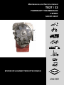
TE27 / 32
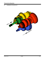
POWERSHIFT TRANSMISSION
4 SPEED
SHORT DROP
SPICER OFF-HIGHWAY PRODUCTS DIVISION
Manual: 8100102
CD-ROM: 8100101
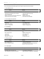
Table of Contents
TOWING OR PUSHING
FOREWORD
1 SAFETY PRECAUTIONS .................................................................................................... 1
2 CLEANING AND INSPECTION ........................................................................................... 1
2.1
2.2
2.3
CLEANING ...................................................................................................................................... 2
2.1.1 BEARINGS ............................................................................................................................ 2
2.1.2 HOUSINGS ............................................................................................................................ 2
INSPECTION .................................................................................................................................... 2
2.2.1 BEARINGS ............................................................................................................................ 2
2.2.2 OIL SEALS, GASKETS, etc. ................................................................................................. 3
2.2.3 GEARS & SHAFTS................................................................................................................ 3
2.2.4 HOUSINGS, COVERS, etc. ................................................................................................... 3
LEGEND SYMBOLS ........................................................................................................................ 3
3 TECHNICAL SPECIFICATIONS .......................................................................................... 1
3.1.
3.2.
3.3
3.4
3.5
3.6
IDENTIFICATION OF THE UNIT ...................................................................................................... 2
WEIGHT, DIMENSIONS, OIL CAPACITY......................................................................................... 2
TIGHTENING TORQUES.................................................................................................................. 3
PRESSURE & TEMPERATURE SPECIFICATIONS ........................................................................ 5
ELECTRICAL SPECIFICATIONS .................................................................................................... 6
HYDRAULIC COOLER LINES SPECIFICATIONS .......................................................................... 6
4 MAINTENANCE
4.1.
4.2
4.3
............................................................................................................... 1
OIL SPECIFICATION........................................................................................................................ 2
4.1.1 RECOMMENDED LUBRICANTS .......................................................................................... 2
MAINTENANCE INTERVALS........................................................................................................... 2
4.2.1 DAILY ..................................................................................................................................... 2
4.2.2 NORMAL DRAIN PERIOD ..................................................................................................... 2
SERVICING MACHINE AFTER COMPONENTS OVERHAUL ......................................................... 3
5 INSTALLATION DETAILS.................................................................................................... 1
5.1
5.2
5.3
CONVERTER DRIVE COUPLING ................................................................................................. 2
TRANSMISSION TO ENGINE INSTALLATION PROCEDURE........................................................ 3
EXTERNAL PLUMBING................................................................................................................... 4
5.3.1 COOLER & FILTER LINES SPECIFICATIONS ...................................................................... 4
5.4
SPEED SENSOR INSTALLATION ................................................................................................... 5
TE27/32 4 SD
12/2002
6 TRANSMISSION OPERATION ............................................................................................ 1
6.1
6.2
6.3
6.4
6.5
THE TRANSMISSION ASSEMBLY .................................................................................................. 2
6.1.1 THE CONVERTER, PUMP DRIVE SECTION AND PRESSURE REGULATING VALVE ...... 3
6.1.2 THE INPUT SHAFT AND DIRECTIONAL CLUTCHES ........................................................ 4
6.1.3 THE RANGE CLUTCHES ..................................................................................................... 5
6.1.4 THE OUTPUT SECTION ....................................................................................................... 5
THE TRANSMISSION CONTROLS (REFER TO HYDRAULIC DIAGRAM) .................................... 6
ELECTRIC SOLENOID CONTROLS ............................................................................................... 6
POWERFLOWS, ACTIVATED SOLENOIDS AND HYDRAULIC CIRCUIT...................................... 7
6.4.1 NEUTRAL SELECTED........................................................................................................... 7
6.4.2 FORWARD 1ST SPEED ........................................................................................................ 9
6.4.3 FORWARD 2ND SPEED...................................................................................................... 11
6.4.4 FORWARD 3RD SPEED...................................................................................................... 13
6.4.5 FORWARD 4TH SPEED ...................................................................................................... 15
6.4.6 REVERSE 1ST SPEED ....................................................................................................... 17
6.4.7 REVERSE 2ND SPEED....................................................................................................... 19
6.4.8 REVERSE 3RD SPEED....................................................................................................... 21
6.4.9 REVERSE 4TH SPEED ....................................................................................................... 23
GEAR AND CLUTCH LAYOUT ....................................................................................................... 25
7 TROUBLESHOOTING GUIDE ............................................................................................. 1
7.1
7.2
7.3
7.4
7.5
THE TRANSMISSION....................................................................................................................... 2
THE INPUT SHAFT AND DIRECTIONAL CLUTCHES .................................................................... 2
7.2.1 STALL TEST .......................................................................................................................... 2
7.2.2 TRANSMISSION PRESSURE CHECK ................................................................................. 3
7.2.3 MECHANICAL AND ELECTRICAL CHECKS ........................................................................ 3
7.2.4 HYDRAULIC CHECKS........................................................................................................... 3
TROUBLESHOOTING GUIDE......................................................................................................... 4
7.3.1 LOW CLUTCH PRESSURE................................................................................................... 4
7.3.2 LOW CHARGING PUMP OUTPUT FLOW ............................................................................ 4
7.3.3 OVERHEATING...................................................................................................................... 4
7.3.4 NOISE CONVERTER............................................................................................................. 4
7.3.5 LACK OF POWER ................................................................................................................. 4
CHECK POINTS ............................................................................................................................... 5
SPEED SENSOR - STATIC STANDALONE TEST........................................................................... 8
8 SECTIONAL VIEWS & PARTS IDENTIFICATION............................................................... 1
TE 27/32 TORQUE CONVERTER GROUP................................................................................................. 2
TE 27/32 TORQUE CONVERTER GROUP................................................................................................. 3
TE 27/32 TRANSMISSION CASE & REAR COVER GROUP .................................................................... 4
TE 27/32 TRANSMISSION CASE & REAR COVER GROUP .................................................................... 5
TE 27/32 TURBINE SHAFT GROUP .......................................................................................................... 6
TE 27/32 TURBINE SHAFT GROUP .......................................................................................................... 7
TE 27/32 PUMP DRIVE GROUP................................................................................................................. 8
TE 27/32 PUMP DRIVE GROUP................................................................................................................. 9
TE 27/32 ADAPTOR SLEEVE GROUP .................................................................................................... 10
TE 27/32 ADAPTOR SLEEVE GROUP .................................................................................................... 11
TE 27/32 WHEEL GROUP ........................................................................................................................ 12
TE 27/32 WHEEL GROUP ........................................................................................................................ 13
TE27/32 4 SD
12/2002
TE 27/32 DRIVE PLATE GROUP ............................................................................................................. 14
TE 27/32 DRIVE PLATE GROUP ............................................................................................................. 15
TE 27/32 FWD & REV/2ND AND 3TH OR 4TH CLUTCH SHAFT ASSY ................................................ 16
TE 27/32 FWD & REV/2ND AND 3TH OR 4TH CLUTCH SHAFT ASSY ................................................ 17
TE 27/32 forward clutch shaft GROUP................................................................................................... 18
TE 27/32 forward clutch shaft GROUP................................................................................................... 19
TE 27/32 3rd speed clucth shaft GROUP ............................................................................................... 20
TE 27/32 3rd speed clucth shaft GROUP ............................................................................................... 21
TE 27/32 3rd speed gear.......................................................................................................................... 22
TE 27/32 3rd speed gear.......................................................................................................................... 23
TE 27/32 REV / 2nd schaft GROUP......................................................................................................... 24
TE 27/32 REV / 2nd schaft GROUP......................................................................................................... 25
TE 27/32 1st speed clutch shaft GROUP ............................................................................................... 26
TE 27/32 1st speed clutch shaft GROUP ............................................................................................... 27
TE 27/32 4th speed clutch shaft GROUP ............................................................................................... 28
TE 27/32 4th speed clutch shaft GROUP ............................................................................................... 29
TE 27/32 1st shaft gear GROUP.............................................................................................................. 30
TE 27/32 1st shaft gear GROUP.............................................................................................................. 31
TE 27/32 Output shaft GROUP................................................................................................................ 32
TE 27/32 output shaft group ................................................................................................................... 33
TE 27/32 Regulator valve group ............................................................................................................. 34
TE 27/32 Regulator valve group ............................................................................................................. 35
TE 27/32 control valve GROUP ............................................................................................................... 36
TE 27/32 control valve GROUP ............................................................................................................... 37
TE 27/32 control valve GROUP (cont.) ................................................................................................... 38
TE 27/32 control valve GROUP (cont.) ................................................................................................... 39
TE 27/32 remote filter adapter GROUP .................................................................................................. 40
TE 27/32 remote filter adaptor GROUP .................................................................................................. 41
9 ASSEMBLY INSTRUCTIONS .............................................................................................. 1
10 DISASSEMBLY AND REASSEMBLY OF THE TRANSMISSION...................................... 1
11 SPECIAL TOOLS ............................................................................................................... 1
TE27/32 4 SD
12/2002
TOWING OR PUSHING
Before towing the vehicle, be sure to lift the rear wheels off the ground or disconnect the driveline to avoid damage to the transmission during towing.
NOTE:
Because of the design of the hydraulic system, the engine cannot be started by pushing or towing.
©Copyright Dana Spicer Off-Higwhay Products Division
Unpublished Material - All rights reserved
Limited Distribution
No part of this work may be reproduced in any form under any means without direct written permission of the
Dana Spicer Off-Highway Products Division
TE27/32-4-SD
12/02
I
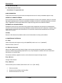
FOREWORD
This manual has been prepared to provide the customer and the maintenance personnel with information and
instructions on the maintenance and repair of the SPICER OFF-HIGWAY PRODUCTS product.
Extreme care has been exercised in the design, selection of materials, and manufacturing of these units. The
slight outlay in personal attention and cost required to provide regular and proper lubrication, inspection at stated
intervals, and such adjustments as may be indicated, will be reimbursed many times in low cost operation and
trouble-free service.
In order to become familiar with the various parts of the product, its principle of operation, troubleshooting and
adjustments, it is urged that the mechanic studies the instructions in this manual carefully and uses it as a reference when performing maintenance and repair operations.
Whenever repair or replacement of component parts is required, only SPICER OFF-HIGHWAY PRODUCTS approved parts as listed in the applicable parts manual should be used. Use of “will-fit” or non-approved parts may
endanger proper operation and performance of the equipment. SPICER OFF-HIGHWAY PRODUCTS does not
warrant repair or replacement parts, nor failures resulting from the use of parts which are not supplied or approved by SPICER OFF-HIGHWAY PRODUCTS.
IMPORTANT
ALWAYS FURNISH THE DISTRIBUTOR WITH THE SERIAL AND MODEL NUMBER WHEN ORDERING PARTS.
TE27/32-4-SD
12/02
II
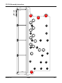
FWD
3RD
2ND
REV
1ST
4TH
TE27/32-4-SD
12/02
III
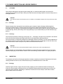
1. SAFETY PRECAUTIONS
To reduce the chance of personal injury and/or property damage, the following instructions must be carefully
observed.
Proper service and repair are important to the safety of the service technician and the safe reliable operation of
the machine. If replacement parts are required the part must be replaced by a spare part which has the same
part number or with an equivalent part. DO NOT USE A SPARE PART OF LESSER QUALITY.
The service procedures recommended in this manual are effective methods for performing service and
repair. Some of these procedures require the use of tools specifically designed for the purpose.
Accordingly, anyone who intends to use a spare parts, service procedure or tool, which is not recommended by
SPICER OFF-HIGHWAY PRODUCTS, must first determine that neither his safety nor the safe operation of the
machine will be jeopardized by the spare part, service procedure or tool selected.
IMPORTANT
It is important to note that this manual contains various ’CAUTIONS’ and ‘NOTES’ that must be carefully observed in
order to reduce the risk of personal injury during service or repair, or the possibility that improper service or repair
may damage the unit or render it unsafe.
It is also important to understand that these ‘CAUTIONS” and ‘NOTES’ are not exhaustive, because it is impossible
to warn about all the possible hazardous consequences that might result from failure to follow these instructions.
TE27/32-4-SD
12/02
1-1
2. CLEANING, INSPECTION AND LEGEND SYMBOLS
2.1
CLEANING
Clean all parts thoroughly using solvent type cleaning fluid. It is recommended that parts be immersed in
cleaning fluid and moved up and down slowly until all old lubricant and foreign material is dissolved and parts are
thoroughly cleaned.
CAUTION
Care should be exercised to avoid skin rashes, fire hazards, and inhalation of vapors when using solvent type cleaners.
2.1.1
Bearings
Remove bearings from cleaning fluid and strike flat against a block of wood to dislodge solidified particles
of lubricant. Immerse again in cleaning fluid to flush out particles. Repeat above operation until bearings are
thoroughly clean. Dry bearings using moisture-free compressed air. Be careful to direct air stream across bearing
to avoid spinning. Do not spin bearings when drying. Bearings may be rotated slowly by hand to facilitate drying
process.
2.1.2
Housings
Clean interior and exterior of housings, bearing caps, etc…, thoroughly. Cast parts may be cleaned in hot solution
tanks with mild alkali solutions providing these parts do not have ground or polished surfaces.
Parts should remain in solution long enough to be thoroughly cleaned and heated. This will aid the evaporation of
the cleaning solution and rinse water. Parts cleaned in solution tanks must be thoroughly rinsed with clean water
to remove all traces of alkali. Cast parts may also be cleaned with steam cleaner.
CAUTION
Care should be exercised to avoid inhalation of vapors and skin rashes when using alkali cleaners.
All parts cleaned must be thoroughly dried immediately by using moisture-free compressed air or soft, lintless
absorbent wiping rags free of abrasive materials such as metal fillings, contaminated oil, or lapping compound.
2.2
INSPECTION
The importance of careful and thorough inspection of all parts cannot be overstressed. Replacement of all parts
showing indication of wear or stress will eliminate costly and avoidable failures at a later date.
2.2.1
Bearings
Carefully inspect all rollers: cages and cups for wear, chipping, or nicks to determine fitness of bearings for
further use. Do not replace a bearing cone or cup individually without replacing the mating cup or cone at the
same time. After inspection, dip bearings in Automatic Transmission Fluid and wrap in clean lintless cloth or
paper to protect them until installed.
TE27/32-4-SD
12/02
2-1
Cleaning, inspection and legend symbols
2.2.2
Oil Seals, Gaskets, Etc.
Replacement of spring load oil seals, “O” rings, metal sealing rings, gaskets, and snap rings is more economical
when unit is disassembled than premature overhaul to replace these parts at a future time.
Further loss of lubricant through a worn seal may result in failure of other more expensive parts of the assembly.
Sealing members should be handled carefully, particularly when being installed. Cutting, scratching, or curling
under of lip of seal seriously impairs its efficiency. When assembling new metal type sealing rings, these should
be lubricated with coat of chassis grease to stabilize rings in their grooves for ease of assembly of mating
members. Lubricate all “O” rings and seals with recommended type Automatic Transmission Fluid before
assembly.
2.2.3
Gears and Shafts
If magna-flux process is available, use process to check parts. Examine teeth on all gears carefully for wear,
pitting, chipping, nicks, cracks, or scores. If gear teeth show spots where case hardening is worn through or
cracked, replace with new gear. Small nicks may be removed with suitable hone. Inspect shafts and quills to
make certain they are not sprung, bent, or splines twisted, and that shafts are true.
2.2.4
Housing, Covers, etc.
Inspect housings, covers and bearing caps to ensure that they are thoroughly clean and that mating surfaces,
bearing bores, etc…, are free from nicks or burrs. Check all parts carefully for evidence of cracks or conditions
which would cause subsequent oil leaks or failures.
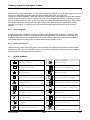
2.3
LEGEND SYMBOLS
Smontaggio di sottogruppi
Sostituire con ogni montaggio
Disassembly of assembly groups
Renew at each reassembly
Montaggio di sottogruppi
Togliere - mettere la sicura
Reassemble to from assembly group
Unlock - lock e.g. split pin, locking plate, etc.
Smontaggio di particollari ingombranti
Mettere la sicura, incollare (mastice liquido)
Remove obstruction parts
Lock - adhere (liquid sealant)
Montaggio di particollari ingombranti
Evitare danni ai materiali, danni ai pezzi
Reinstall - remount parts which had obstructed disassembly
Guard against material damage, damage to parts
Attenzione, indicazione importante
Marchiari prima dello smontaggio (per il montaggio)
Attention! important notice
Mark before disassembly, observe marks when reasembl.
Controllare regolare p.e. coppie, misure, pressione etc.
Carricare riempire (olio - lubrificante)
Check - adjust e.g. torque, dimensions, pressures etc.
Filling - topping up - refilling e.g. oil, cooling water, etc.
T = Attrezzature speciali
Scarricare olio, lubrificante
T = Special tool
TE27/32-4-SD
P = Pagina
P = Page
Drain off oil, lubricant
Rispettare direzione di montaggio
Tendere
Note direction of installation
Tighten - clamp ; tightening a clamping device
Controllare esaminare controllo visuale
Insere pressione nel circuito idraulico
Visual inspection
Apply pressure into hydraulic circuit
Eventualimente riutilizzable (sostituire se necessario)
Pulire
Possibly still serviceable, renew if necessary
To clean
12/02
2-2
3. TECHNICAL SPECIFICATIONS
TE27/32 4 SD
12/2002
3-1
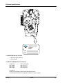
Technical specifications
SPICER OFF-HIGHWAY
TEN BRIELE 3
B-8200
BELGIUM
MODEL
SERIAL
3.1 IDENTIFICATION OF THE UNIT
1. Model and type of the unit
2. Serial number
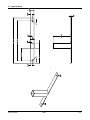
3.2 WEIGHT, DIMENSIONS, OIL CAPACITY
Weight (dry)
Max. length
Max. width
Max. heigth
865 Kg [1903 lbs]
940 mm [37.0"]
665 mm [26.2"]
970 mm [38.2"]
Oil capacity
60 liter [15.9 US gallon] without cooler and hydraulic lines.
Consult Operators manual on applicable machine for system capacity.
TE27/32
12/2002
3-2
Technical specifications
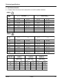
3.3 TIGHTENING TORQUES
3.3.1 TORQUE SPECIFICATIONS FOR LUBRICATED OR PLATED SCREW THREADS
GRADE 5
NOM.
SIZE
LB - FT
N-m
LB - FT
7500
223 - 245
302 - 332
200 - 220
271 - 298
6250
128 - 141
174 - 191
113 - 124
153 - 168
5625
91 - 100
123.4 - 135.5
82 - 90
111.2 - 122.0
5000
64 - 70
86.8 - 94.9
57 - 63
77.3 - 85.4
4375
41 - 45
55.6 - 61.0
37 - 41
50.2 - 55.5
3750
26 - 29
35.3 - 39.3
23 - 25
31.2 - 33.8
3125
16 - 20
21.7 - 27.1
12 - 16
16.3 - 21.6
2500
9 - 11
12.3 - 14.9
8 - 10
10.9 - 13.5
FINE THREAD
COARSE THREAD
N-m
GRADE 8
NOM.
SIZE
LB - FT
N-m
LB - FT
7500
315 - 347
427 - 470
282 - 310
382 - 420
6250
180 - 198
244 - 268
159 - 175
216 - 237
5625
128 - 141
173.6 - 191.1
115 - 127
156.0 - 172.2
5000
90 - 99
122.1 - 134.2
80 - 88
108.5 - 119.3
4375
58 - 64
78.7 - 86.7
52 - 57
70.6 - 77.2
3750
37 - 41
50.2 - 55.5
33 - 36
44.8 - 48.8
3125
28 - 32
38.0 - 43.3
26 - 30
35.3 - 40.6
2500
11 - 13
15.0 - 17.6
9 - 11
12.3 - 14.9
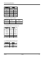
NOM. SIZE
CLASS 8.8
FINE THREAD
COARSE THREAD
LBF - FT
[N.m]
TE27/32
M5
4-5
[5 - 6]
M6
6-7
M8
M10
CLASS 10.9
COARSE THREAD
LBF - FT
[N.m]
COARSE THREAD
N-m
GRADE 12.9
COARSE THREAD
LBF - FT
[N.m]
[7 - 8]
6-7
[8 - 10]
[8 - 10]
5-6
9 - 11
[12 - 15]
10 - 12
[13 - 16]
15 - 18
[20 - 25]
22 - 26
[30 - 35]
26 - 30
[35 - 40]
30 - 37
[40 - 50]
44 - 48
[60 - 65]
48 - 55
[65 - 75]
12/2002
3-3
Technical specifications
THREAD SIZE
TORQUE
LBF - FT
[N.m]
M10 x 1
6 -7
[8 - 10]
M14 x 1.5
7-9
[10 - 12]
M18 x 1.5
25 - 30
[34 - 41]
M22 x 1.5
35 - 44
[48 - 60]
M33 x 2
83 -103
[112 - 140]
3.3.2 ELASTIC STOP NUT TORQUE
THREAD SIZE
LBF - FT
[N . m]
9/16" - 18
12 - 15
[16 - 20]
3/4" - 16
20 - 25
[27 - 34]
3.3.3 TORQUE TABLES FOR O-RING PLUGS
TORQUE
THREAD SIZE
NPTF
LBF - FT
[N.m]
1/16 x 27
5 -7
[7 - 8]
1/8 x 27
7 - 10
[9 - 14]
1/4 x 18
15 - 20
[20 - 27]
3/8 x 18
25 - 30
[34 - 41]
1/2 x 14
30 - 35
[41 - 47]
3/4 x 10
40 - 45
[54 - 61]
3.3.4 TORQUE TABLE FOR PIPE PLUGS
THREAD SIZE
M18 x 1.5 6H
M26 x 1.5 6H
TE27/32
TORQUE
LBF - FT
[N.m]
25 - 30
45 - 50
[34 - 41]
[61 - 68]
12/2002
3-4
Technical specifications
3.4 PRESSURE & TEMPERATURE SPECIFICATIONS
Normal operating temperature 70 - 120°C [158-248° F] measured at temperature check port to cooler (port 71 - **).
maximum allowed transmission temperature 120° C [248° F].
Transmission regulator presure (*) - neutral - port 31 (**).
at 600 RPM 17 bar [246.5 PSI] minimum
at 2650 RPM 22 bar [319.0 PSI] maximum
Pump flow (*)
System pump flow:100.5 l/min [26.34 GPM] at 1973 RPM.
Lube pump flow:
85.1 l/min [22.48 GPM] at 1973 RPM.
Clutch pressures (*)
1st clutch
2nd clutch
3rd clutch
Fwd clutch
Rev clutch
port 41 (**)
port 42 (**)
port 43 (**)
port 45 (**)
port 46 (**)
at 2200 RPM
21.5 - 25.5 bar [311.8 - 369.8 PSI] activated.
Filter bypass valve set at 4.1 to 4.5 bar (*) [59.4 to 65.2 PSI].
Lube pressure (*) port 33 1.76 - 2.64 bar [25.5 - 38.2 PSI] at 73 l/min. [19.2 GPM] converter flow.
Internal total leakage at 1000 engine RPM
Fwd/Rev
4 l/min [1 GPM]
1st
10.5 l/min [2.7 GPM]
2nd/3rd/4th
4 l/min [1 GPM]
Safety valve: cracking pressure (*) 9.0 bar [130.5 PSI]
To cooler (convereter out) pressure (*) port 32 - 2 bar min. [29.0 PSI] at 2000 RPM and max. 5.0 bar [72.5 PSI] at
no load governed speed.
(*) All pressures and flows to be measured with oil temperature of 82 - 93° C [180-200° F]
(**) Refer to section troubleshooting for check port identification.
TE27/32
12/2002
3-5
Technical specifications
3.5 ELECTRICAL SPECIFICATIONS
Electronic controlled modulation valves
VFS 2nd/4th - VFS 1st/3rd - VFS Fwd -VFS Rev
coil resistance 4.35 ± 0.35 Ω at 25° C [77° F]
On/Off Solenoids
Total neutral and 1st/3rd & 2nd/4th range solenoids
Coil resistance 12V - 28 ± 2 Ω at 20° C [68° F]
Coil resistance 24V - 28 ± 2 Ω at 20° C [68° F]
Speed sensor
Type
Sensing distance
Sensor signal
Magneto resistive sensor.
0- 1.8 mm [0 - 0.07"]
generates a square current with a fixed amplitude changing between 7 and 14 mA.
3.6 HYDRAULIC COOLER LINES SPECIFICATIONS.
Minimum 37 mm [1.25"] internal diameter for lines and fittings.
Suitable for operation from ambient to 120° C [248° F] continuous operating temperature.
Must withstand 30 bar [435 PSI] continuous pressure and 45 bar [652 PSI] intermittent surges.
Conform SAE J1019 and SAE J517, 100RI.
TE27/32
12/2002
3-6
4. MAINTENANCE
TE27/32 4 SD
12/2002
4-1
Maintenance
4.1. OIL SPECIFICATION
4.1.1 Recommended lubricants
• Only
Dexron* III is approved to use
SUMP PREHEATERS
Preheat the transmission fluid to the mimimum temperature for the oil viscosity used before engine startup.
NORMAL OIL CHANGE INTERVAL
Drain and refill system every 1000 hrs for average environmental and duty cycle conditions. Severe or sustained
high operating temperature or very dusty atmospheric conditions will result in accelerated detioration or contamination. Judgement must be used to determine the required change intervals for extreme conditions.
EXTENDED OIL CHANGE INTERVAL
Extended oil service life may result when using synthetic fluids. Appropriate change intervals should be determined for each transmission by measuring oil oxidation and wear metals over time, to determine a baseline. Wear
metals analysis can provide useful inforamtion but a transmission should not be removed from service based
solely on this analysis.
FILTERS
Service oil filter element every 500 hrs under normal envirronmental and duty cycle conditions.
4.2 MAINTENANCE INTERVALS
4.2.1 Daily
Check oil level daily with engine running at idle (600 RPM) and oil at 82 - 93 °C (180-200 F).
Maintain oil level at full mark.
4.2.2 Normal drain period
Normal drain period and oil filter element change are for average environment and duty cycle condition.
Severe or sustained high operating temperature or very dusty atmospheric conditions will cause accelerated
deterioration and contamination.
For extreme conditions judgement must be used to determine the required change intervals.
Every 500 hours
Change oil filter element.
Every 1000 hours
Drain and refill system as follows (Drain with oil at 65 - 93 °C [150 - 200 F]):
1.
Drain transmission.
2.
Remove and discard filter. Install new filter.
3.
Refill transmission to FULL mark.
TE27/32 4 SD
12/2002
4-2
Maintenance
4.
Run engine at 500 - 600 RPM to prime convertor and lines.
5.
Recheck level with engine running at 500 - 600 RPM and add oil to bring level to LOW mark.
When oil temperature is hot 82.2 - 93.3 °C (180- 200 F) make final oil level check and adjust if
ecessary to bring oil level to FULL mark.
NOTE
IT IS RECOMMENDED THAT OIL FILTER BE CHANGED AFTER 100 HOURS OF OPERATION ON NEW, REBUILT OR
REPAIRED UNIT.
4.3 SERVICING MACHINE AFTER COMPONENTS OVERHAUL
The transmission, torque converter, and its allied hydraulic system are important links in the driveline between
the engine and the wheels. The proper operation of either unit depends greatly on the condition and operation
of the other. Therefore, whenever repair or overhaul of one unit is performed, the balance of the system must be
considered before the job can be considered complete.
After the overhauled or repaired transmission has been installed in the machine, the oil cooler, and connecting
hydraulic system must be thoroughly cleaned. This can be accomplished in several manners and a degree of
judgement must be exercised as to the method employed.
The following are considered the minimum steps to be taken:
1. Drain entire system thoroughly.
2. Disconnect and clean all hydraulic lines. Where feasible hydraulic lines should be removed from machine
for cleaning.
3.
Replace oil filter element.
4. The oil cooler must be thoroughly cleaned. The cooler should be “back flushed” with oil and compressed
air until all foreign material has been removed. Flushing in direction of normal oil flow will not adequately
clean the cooler. If necessary, cooler assembly should be removed from machine for cleaning, using oil,
compressed air, and steam cleaner for that purpose. DO NOT use flushing compounds for cleaning purposes
IMPORTANT
DO NOT USE FLUSHING COMPOUNDS FOR CLEANING PURPOSES.
5. Reassemble all components and use only type oil recommended for lubrication section.
Fill transmission through filler opening until fluid comes up to the oil level check port.
Run engine 2 minutes at 500+600 R.P.M. to prime torque converter and hydraulic lines.
Recheck level of fluid in transmission with engine running at idle (500-600 R.P.M.).
Add quantity necessary to bring fluid level to oil level check port.
Recheck with hot oil (180-200 F) 82-93° C.
6. Recheck all drain plugs, lines, connections, etc., for leaks and tighten where necessary.
* DEXRON is a registered trademark of GENERAL MOTORS CORPORATION
TE27/32 4 SD
12/2002
4-3
5. INSTALLATION DETAILS
TE27/32 4 SD
12/2002
5-1
Installation details
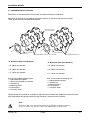
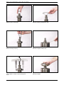
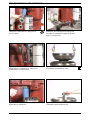
5.1 CONVERTER DRIVE COUPLING
Measure the “A” dimension (bolt circle diameter) and order drive plate kit listed below.
Note three (3) kits have (2) intermediate drive plates and one (1) drive plate and weld nut assembly.
Three (3) kits with three intermediate drive plates.
(1) DRIVE PLATE AND
WELD NUT ASSEMBLY
A
A
BOLT CIRCLE DIA.
BACKING RING
BOLT CIRCLE DIA.
(2) INTERMEDIATE DRIVE PLATES
BACKING RING
(3) INTERMEDIATE DRIVE PLATES
“A” Dimension (Bolt circle diameter)
“A” Dimension (Bolt circle diameter)
• 15” (381.0 mm) diameter
• 15” (381.0 mm) diameter
• 16” (406.4 mm) diameter
• 16” (406.4 mm) diameter
• 17” (431.8 mm) diameter
• 17” (431.8 mm) diameter
Each kit will include the following parts:
• 2 Intermediate drive plates
• 1 Drive plate and weld nut assembly
• 1 Backing ring
• 6 Mounting screws
• 6 Lock washers
• 1 Instruction sheet
Each kit will include the following parts:
• 3 Intermediate drive plates
• 1 Backing ring
• 6 Mounting screws
• 6 Lock washers
• 1 Instruction sheet
Position drive plate and weld nut assembly on torque converter assembly with welded nuts toward converter.
Align intermediate drive plates and backing ring with holes in torque converter assembly.
NOTE:
TWO DIMPLES 180° APART IN BACKING RING MUST BE OUT (TOWARD THE ENGINE FLYWHEEL).
INSTALL CAP SCREWS AND WASHERS. TIGHTEN 40 - 50 NM [30 TO 37 LBFT] TORQUE.
TE27/32 4 SD
12/2002
5-2
Installation details
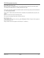
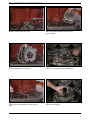
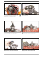
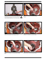
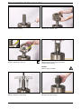
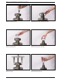
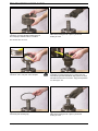
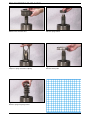
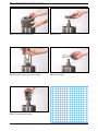
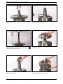
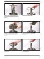
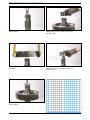
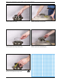
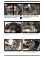
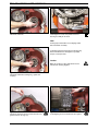
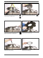
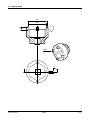
5.2 TRANSMISSION TO ENGINE INSTALLATION
PROCEDURE
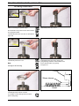
1. Remove all burrs from flywheel mounting face and nose
pilot bore. Clean drive plate surface with solvent.
2. Check engine flywheel & housing for conformance to
standard SAE No. 3 per SAE J927 and J1033 tolerance
specifications for pilot bore size, pilot bore runout and
mounting face flatness. Measure and record engine
crankshaft end play (Fig. 1).
3. Install two 63,50 mm (2.50”) long transmission to
flywheel housing guide studs in the engine flywheel
housing as shown. Rotate the engine flywheel to align a
drive plate mounting screw hole with the flywheel housing access hole (Fig. 2).
FLYWHEEL H OUSING
MOUNT
DIAL INDICATOR
HERE
ENGINE
FLYWHEEL
PILOT BORE
FLYWHEEL
FIG. 1
CONVERTER HOUSING
FLYWHEEL HOUSING
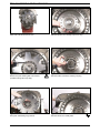
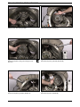
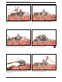
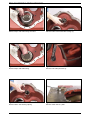
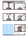
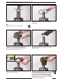
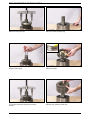
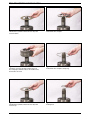
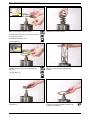
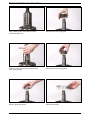
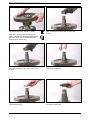
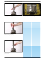
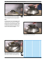
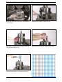
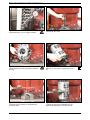
*4. Install a 101,60 mm (4.00”) long drive plate locating stud
.3750-24 fine thread in a drive plate nut. Align the locating stud in the drive plate with the flywheel drive plate
mounting screw hole positioned in step No. 3.
4"STUD
5. Rotate the transmission torque converter to align the
locating stud in the drive plate with the flywheel drive
plate mounting screw hole positioned in step No. 3.
Locate transmission on flywheel housing.
Aligning drive plate to flywheel and transmission to
flywheel housing guide studs. Install transmission to
flywheel housing screws. Tighten screws to specified
torque. Remove transmission to engine guide studs.
Install remaining screws and tighten to specified torque.
21/2"ALIGNING
STUDS
DRIVE
PLATE
FLYWHEEL
FIG. 2
FLYWHEEL HOUSING
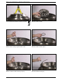
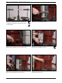
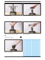
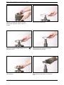
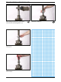
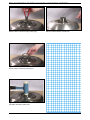
*6. Remove drive plate locating stud.
7. Install drive plate attaching screw and washer. Snug
screw but do not tighten. Some engine flywheel
housings have a hole located on the flywheel housing
circumference in line with the drive plate screw access
hole. A screwdriver or pry bar used to hold the drive
plate against the flywheel will facilitate installation of
the drive plate screws. Rotate the engine flywheel and
install the remaining seven (7) flywheel to drive plate
attaching screws. Snug screws but do not tighten.
After all eight (8) screws are installed.
Torque each one 35 to 39 N.m. (26- 29ft.lbs.). This will
require tightening each screw and rotating the engine
flywheel until the full amount of eight (8) screws have
been tightened to specified torque.
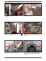
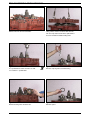
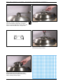
FLYWHEEL
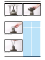
IMPELLER
COVER
INTERMEDIATE
DRIVE PLATES
FIG.4
FIG. 3
PLATES TO BE INSTALLED
WITH CONCAVE SIDE
TOWARD ENGINE FLYWHEEL.
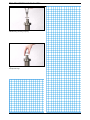
8. Measure engine crankshaft end play after transmission
has been completely installed on engine flywheel. This
value must be within 0,025 mm (0.001”) of the end play
recorded in step No. 2.
* Does not apply to units having 3 intermediate drive plates.
See Fig.4.
TE27/32 4 SD
SPECIAL STUD, WASHER AND
SELF LOCK NUT FURNISHED
BY ENGINE MANUFACTURER.
12/2002
FIG. 5
5-3
Installation details
5.3
EXTERNAL PLUMBING
cooler
from cooler to transmission
from remote filter 2
from transmission to cooler
remote filter 2
from remote filter 1
to remote filter 1
from pump 1
remote filter 1
5.3.1
Cooler & filter lines specifications
• Minimum 32 mm [1.25 inch] internal diameter for lines and fittings.
• Suitable for operation from ambient to 120° C [248° F] continuous operating temperature.
• Must withstand 30 bar [435psi] continuous pressure and with 40 bar [652 psi] intermittent surges.
• Conform SAE J1019 and SAE J517,100RI.
TE27/32 4 SD
12/2002
5-4
Installation details
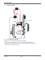
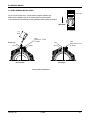
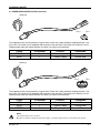
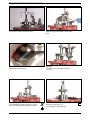
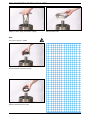
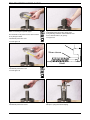
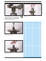
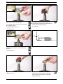
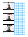
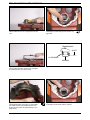
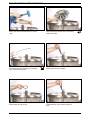
5.4 SPEED SENSOR INSTALLATION
Position sign
On the sensor body there is a small plastic triangular position sign.
Make sure the position sign on the sensor points as shown below
in the direction of the movement of the gearteeth (Teeth rotation as shown).
Teeth rotation
1.65
(42.0)
Screw
Tighten to 5.9 - 7.4 lbf-ft
(8 - 10 Nm)
Position sign
"O"-ring
Screw
Tighten to 5.9 - 7.4 lbf-ft
(8 - 10 Nm)
Plug
Support
"O"-ring
Sensor installed
Hole plugged
Sensor position on transmission
Turbine speed sensor location
Engine speed sensor location
FP
FC
3C
2P
2C
RC
RP
1P
Right side view
TE27/32 4 SD
12/2002
5-5
Installation details
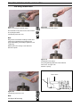
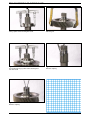
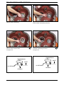
5.4 SPEED SENSOR INSTALLATION (CONTINUED)
Position sign
Pin 2
Pin 1
The magneto resistive sensor generates a square wave current with a fixed amplitude changing between 7 mA
and 14 mA. The sensor has an integrated AMP superseal 2 pin connector. The two pins are numbered 1 and 2.
Following table shows the relation between wire colour, pin number and connection.
Colour
BROWN
BLUE
Pin Number
1
2
Function
Current Input
Current Output
Connection
Hot wire
Ground Wire
Position sign
Pin 3
Pin 1
Pin 2
The magneto resistive sensor generates a square wave current with a fixed amplitude changing between 7 mA
and 14 mA. The sensor has an integrated AMP superseal 2 pin connector. The two pins are numbered 1 and 2.
Following table shows the relation between wire colour, pin number and connection.
Colour
RED
BLUE
GREEN
Pin Number
1
2
3
Function
Current Input
Current Output
Temp. Input
Connection
Hot Wire
Ground Wire
Hot Wire
NOTE:
THE SENSOR WIRES HAVE A POLARITY.
BE SURE TO CORRECTLY OBSERVE SENSOR POLARITIES, AS WRONG CONNECTIONS WILL DEACTIVATE THE SENSOR.
TE27/32 4 SD
12/2002
5-6
6. TRANSMISSION OPERATION
TE27/32-4-SD
12/2002
6-1
Transmission Operation
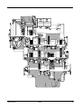
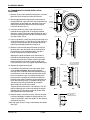
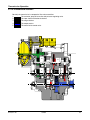
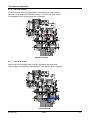
6.1 THE TRANSMISSION ASSEMBLY
Basically the transmission is composed of five main assemblies:
1.
The converter, pump drive section and pressure regulating valve.
2.
The input shaft and directional clutches.
3.
The range clutches.
4.
The output section.
5.
The transmission control valve.
FWD
REV
3RD
2ND
1ST
4TH
TE27/32-4-SD
12/2002
6-2
Transmission Operation
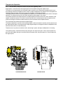
6.1.1
The converter, pump drive section and pressure regulating valve
Engine power is transmitted from the engine flywheel to the impeller through the impeller cover.
This element is the pump portion of the hydraulic torque converter and is the primary component which starts
the oil flowing to the other components which results in torque multiplication. This element can be compared to a
centrifugal pump, that picks up fluid at its centre and discharges it at the outer diameter.
The torque converter turbine is mounted opposite the impeller and is connected to the turbine shaft of the torque
converter. This element receives fluid at its outer diameter and discharges it at its centre.
The reaction member of the torque converter is located between and at the centre of the inner diameters of the
impeller and turbine elements. Its function is to take the fluid which is exhausting from the inner portion of the
turbine and change its direction to allow correct entry for recirculation into the impeller element.
This recirculation will make the converter to multiply torque.
The torque multiplication is function of the blading (impeller, turbine and reaction member) and the converter output speed (turbine speed). The converter will multiply engine torque to its designed maximum multiplication ratio
when the turbine shaft is at zero RPM (stall).
Therefore we can say that as the turbine shaft is decreasing in speed, the torque multiplication is increasing.
The hydraulic pump is connected with the pump drive gear. This pump drive gear is driven by the impeller hub
gear. Since the impeller hub gear is connected with the impeller cover, the pump speed is in direct relation with
the engine speed.
FWD
REV
3RD
2ND
1ST
4TH
CONVERTER SECTION
TE27/32-4-SD
CONTROL VALVE
12/2002
6-3
Transmission Operation
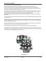
6.1.2
The input shaft and directional clutches
The turbine shaft driven from the turbine transmits power to the directional clutches (fwd/rev.).
These clutches consist of a drum with internal splines and a bore to receive a hydraulic actuated piston.
The piston is oil tight by the use of sealing rings. The steel discs with internal splines, and friction discs with external splines, are alternated until the required total is achieved.
A back-up plate is then inserted and secured with a retainer ring. A hub with outer diameter splines is inserted
into the splines of discs with teeth on the inner diameter. The discs and hub are free to increase in speed or
rotate in the opposite direction as long as no pressure is present in that specific clutch.
To engage the clutch, the solenoid will direct oil under pressure through tubes and passages to the selected
clutch shafts.
Oil sealing rings are located on the clutch shafts. These rings direct the oil through a drilled passage in the shaft
to the desired clutch.
Pressure of the oil forces the piston and discs against the back-up plate. The discs with splines on the outer diameter clamping against discs with teeth on the inner diameter enables the drum and hub to be locked together
and allows them to drive as one unit.
When the clutch is released, a return spring will push the piston back and oil will drain back via the shift spool,
the bleed valve or holes in the clutch piston into the transmission sump.
These bleed valves will only allow quick escape of oil when the pressure to the piston is released.
(The engagement of all range and directional clutches is modulated and electronically controlled.). This means
that clutch pressure is built up gradually. This will enable the unit to make forward, reverse shifts while the vehicle
is still moving and will allow smooth engagement of drive.
FWD
REV
3RD
2ND
1ST
4TH
INPUT SECTION
TE27/32-4-SD
12/2002
6-4
Transmission Operation
6.1.3
The range clutches
Once a directional clutch is engaged power is transmitted to the range clutches.
Operation and actuation of the directional clutches is similar to the range clutches.
The engagement of the directional clutches is modulated.
FWD
REV
3RD
2ND
1ST
4TH
RANGE CLUTCHES
6.1.4
The output section
With a range clutch engaged, power is finally transmitted to the output shaft.
Output rotation is the opposite to input rotation when the forward clutch is engaged.
FWD
REV
3RD
2ND
1ST
4TH
OUTPUT SECTION
TE27/32-4-SD
12/2002
6-5
Transmission Operation
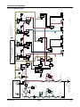
6.2 THE TRANSMISSION CONTROLS (REFER TO HYDRAULIC DIAGRAM)
The transmission is controlled by an APC200 box. This unit has a microprocessor that receives certain inputs
(gear selector position, speed senors,...), which are processed and will give output signals to the control valve.
Operation of the valve
Regulated pressure 22 bar [319 PSI] is directed to the total neutral shift spool and the pressure reducer that will
decrease the pressure to 10 bar [145 psi].
This reduced pressure will be used to supply the electronic controlled modulation valves, total neutral solenoid,
3rd/1st solenoid and 4th/2nd solenoid.
When activated the electronic controlled modulation valves will give an output pressure curve from 0 to 6 bar
[0-87PSI]. The pressure intensifiers will multiply this pressure curve so that a curve from 0 to 20 bar [290 PSI] is
available for each directional and range clutches. Between each electronic controlled modulation valve and pressure intensifier is placed an accumulator to dampen any hydraulic vibration.
In neutral position, the total neutral solenoid is not activated and no pressure is supplied to the pressure intensifiers. Total neutral solenoid will be activated only when forward or reverse direction is requested.
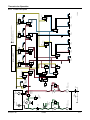
When forward is selected, total neutral solenoid and forward electronic modulation valve are activated. The forward clutch is fed with modulated pressure supplied through the forward pressure intensifier.
When reverse is selected, total neutral solenoid and reverse electronic modulation valve are activated. The reverse clutch is fed with modulated pressure supplied through the reverse pressure intensifier.
Range selection
3rd and 4th clutch are fed with modulated pressure supplied through their respective pressure intensifiers and
electronic controlled modulation valves.
1st clutch is selected when 1st/3rd electronic controlled modulation valve and 1st/3rd solenoid are activated.
The pilot pressure of the 1st/3rd solenoid will move the shift spool so that 1st clutch can be fed with modulated
pressure.
2nd clutch is selected when 4th/2nd electronic controlled modulation valve and 4th/2nd solenoid are activated.
The pilot pressure of the 4th/2nd solenoid will move the shift spool so that 2st clutch can be fed with modulated
pressure.
Pressure switch
The control valve also has a pressure switch installed between the total neutral shift spool and the pressure intensifiers supply. This switch will verify that pressure to the various pressure intensifiers is supplied only when the
total neutral solenoid is activated. This information is an input of the APC200 box.
6.3 ELECTRIC SOLENOID CONTROLS
Transmission gear
Forward 4
Forward 3
Forward 2
Forward 1
Activated solenoids
N,FWD, 2nd/4th
N, FWD, 1st/3rd
N, FWD, 2nd/4th, 2nd/4th range
N, FWD, 1st/3rd, 1st/3rd range
Activated clutches
Forward, 4th
Forward, 3rd
Forward, 2nd
Forward, 1st
N, REV, 1st/3rd
N, REV, 2nd/4th, 2nd/4th range
N, REV, 1st/3rd, 1st/3rd range
Reverse, 3rd
Reverse, 2nd
Reverse, 1st
Neutral
Reverse 3
Reverse 2
Reverse 1
TE27/32-4-SD
12/2002
6-6
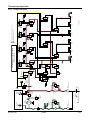
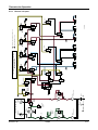
TE27/32-4-SD
12/2002
HOSE
FILTER 2
HOSE
HOSE
HOSE
OIL SUMP
PUMP 2
85,1 L/min at 1973 rpm
BY-PASS VALVE
4,1-4,5 bar
LUBRICATION
COOLER
TORQUE
CONVERTER
AIR
BREATHER
SAFTY VALVE
CRACKING
9 bar
HOSE
FILTER 1
HOSE
PRESSURE
REGULATOR
VALVE 22 bar
PRESSURE
GAUGE
OPERATOR COMPARTMENT
1
SCREEN
PUMP 1
100,5 L/min at 1973 rpm
BY-PASS VALVE
4,1-4,5 bar
3
2
PRESSURE
REDUCER
VALVE 12 bar
TOTAL NEUTRAL
B
A
FWD
CLUTCH
2ND
CLUTCH
B
A
4THD
CLUTCH
4THD / 2ND
B
A
REV
CLUTCH
B
HTE32NEUTRAL
1ST
CLUTCH
A ELECTRONIC CONTROLLED MODULATION VALVE 6 TO 0 bar
B PRESSURE INTENSIFIER 0-6 TO 0-20 bar
A
3RD
CLUTCH
3RD / 1ST
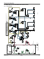
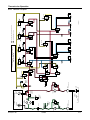
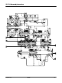
6.4.1
TEMPERATURE
GAUGE
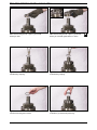
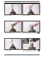
TE32 TRANSMISSION - HYDRAULIC DIAGRAM
NEUTRAL SELECTED
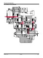
Transmission Operation
6.4 POWERFLOWS, ACTIVATED SOLENOIDS AND HYDRAULIC CIRCUIT
Neutral Selected
6-7
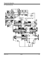
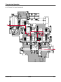
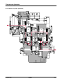
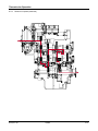
Transmission Operation
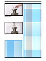
6.4.1 Neutral (Continued)
3RD
FWD
REV
1ST
4TH
TE27/32-4-SD
12/2002
6-8
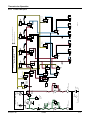
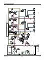
TE27/32-4-SD
12/2002
HOSE
FILTER 2
HOSE
HOSE
HOSE
OIL SUMP
PUMP 2
85,1 L/min at 1973 rpm
BY-PASS VALVE
4,1-4,5 bar
LUBRICATION
RANGE
CLUTCHES
COOLER
TORQUE
CONVERTER
AIR
BREATHER
SAFTY VALVE
CRACKING
9 bar
HOSE
FILTER 1
HOSE
PRESSURE
REGULATOR
VALVE 22 bar
PRESSURE
GAUGE
1
SCREEN
PUMP 1
100,5 L/min at 1973 rpm
BY-PASS VALVE
4,1-4,5 bar
3
2
PRESSURE
REDUCER
VALVE 12 bar
TOTAL NEUTRAL
A
B
FWD
CLUTCH
2ND
CLUTCH
B
A
4THD
CLUTCH
4THD / 2ND
B
A
REV
CLUTCH
B PRESSURE INTENSIFIER 0-6 TO 0-20 bar
B
HTE32FWD1ST
1ST
CLUTCH
A
A ELECTRONIC CONTROLLED MODULATION VALVE 6 TO 0 bar
3RD
CLUTCH
3RD / 1ST
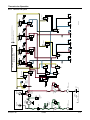
6.4.2
TEMPERATURE
GAUGE
OPERATOR COMPARTMENT
TE32 TRANSMISSION - HYDRAULIC DIAGRAM
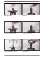
FWD 1ST SELECTED
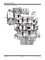
Transmission Operation
Forward 1st speed
6-9
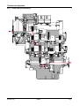
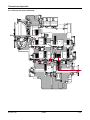
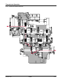
Transmission Operation
6.4.2 Forward 1st speed (continued)
FWD
3RD
1ST
REV
2ND
4TH
TE27/32-4-SD
12/2002
6-10
TE27/32-4-SD
12/2002
HOSE
FILTER 2
HOSE
HOSE
HOSE
OIL SUMP
PUMP 2
85,1 L/min at 1973 rpm
BY-PASS VALVE
4,1-4,5 bar
LUBRICATION
RANGE
CLUTCHES
COOLER
TORQUE
CONVERTER
AIR
BREATHER
SAFTY VALVE
CRACKING
9 bar
HOSE
FILTER 1
HOSE
PRESSURE
REGULATOR
VALVE 22 bar
PRESSURE
GAUGE
1
SCREEN
PUMP 1
100,5 L/min at 1973 rpm
BY-PASS VALVE
4,1-4,5 bar
3
2
PRESSURE
REDUCER
VALVE 12 bar
TOTAL NEUTRAL
A
B
FWD
CLUTCH
A
2ND
CLUTCH
B
4THD
CLUTCH
4THD / 2ND
B
A
REV
CLUTCH
B PRESSURE INTENSIFIER 0-6 TO 0-20 bar
1ST
CLUTCH
A ELECTRONIC CONTROLLED MODULATION VALVE 6 TO 0 bar
B
A
3RD
CLUTCH
HTE32FWD2ND
3RD / 1ST
6.4.3
TEMPERATURE
GAUGE
OPERATOR COMPARTMENT
TE32 TRANSMISSION - HYDRAULIC DIAGRAM
FWD 2ND SELECTED
Transmission Operation
Forward 2nd speed
6-11
Transmission Operation
6.4.3 Forward 2nd speed (continued)
FWD
3RD
REV
2ND
1ST
4TH
TE27/32-4-SD
12/2002
6-12
TE27/32-4-SD
12/2002
HOSE
FILTER 2
HOSE
HOSE
HOSE
OIL SUMP
PUMP 2
85,1 L/min at 1973 rpm
BY-PASS VALVE
4,1-4,5 bar
LUBRICATION
RANGE
CLUTCHES
COOLER
TORQUE
CONVERTER
AIR
BREATHER
SAFTY VALVE
CRACKING
9 bar
HOSE
FILTER 1
HOSE
PRESSURE
REGULATOR
VALVE 22 bar
PRESSURE
GAUGE
1
SCREEN
PUMP 1
100,5 L/min at 1973 rpm
BY-PASS VALVE
4,1-4,5 bar
3
2
PRESSURE
REDUCER
VALVE 12 bar
TOTAL NEUTRAL
A
B
FWD
CLUTCH
2ND
CLUTCH
B
A
4THD
CLUTCH
4THD / 2ND
B
A
REV
CLUTCH
B PRESSURE INTENSIFIER 0-6 TO 0-20 bar
B
HTE32FWD3RD
1ST
CLUTCH
A
A ELECTRONIC CONTROLLED MODULATION VALVE 6 TO 0 bar
3RD
CLUTCH
3RD / 1ST
6.4.4
TEMPERATURE
GAUGE
OPERATOR COMPARTMENT
TE32 TRANSMISSION - HYDRAULIC DIAGRAM
FWD 3RD SELECTED
Transmission Operation
Forward 3rd speed
6-13
Transmission Operation
6.4.4 Forward 3rd speed (continued)
FWD
REV
3RD
2ND
1ST
4TH
TE27/32-4-SD
12/2002
6-14
TE27/32-4-SD
12/2002
HOSE
FILTER 2
HOSE
HOSE
HOSE
OIL SUMP
PUMP 2
85,1 L/min at 1973 rpm
BY-PASS VALVE
4,1-4,5 bar
LUBRICATION
RANGE
CLUTCHES
COOLER
TORQUE
CONVERTER
AIR
BREATHER
SAFTY VALVE
CRACKING
9 bar
HOSE
FILTER 1
HOSE
PRESSURE
REGULATOR
VALVE 22 bar
PRESSURE
GAUGE
OPERATOR COMPARTMENT
1
SCREEN
PUMP 1
100,5 L/min at 1973 rpm
BY-PASS VALVE
4,1-4,5 bar
3
2
PRESSURE
REDUCER
VALVE 12 bar
TOTAL NEUTRAL
A
B
FWD
CLUTCH
A
2ND
CLUTCH
B
4THD
CLUTCH
4THD / 2ND
B
A
REV
CLUTCH
B
A
HTE32FWD4TH
1ST
CLUTCH
A ELECTRONIC CONTROLLED MODULATION VALVE 6 TO 0 bar
B PRESSURE INTENSIFIER 0-6 TO 0-20 bar
3RD
CLUTCH
3RD / 1ST
6.4.5
TEMPERATURE
GAUGE
TE32 TRANSMISSION - HYDRAULIC DIAGRAM
FWD 4TH SELECTED
Transmission Operation
Forward 4th speed
6-15
Transmission Operation
6.4.5
Forward 4th speed (continued)
FWD
REV
3RD
2ND
1ST
4TH
TE27/32-4-SD
12/2002
6-16
TE27/32-4-SD
12/2002
HOSE
FILTER 2
HOSE
HOSE
HOSE
OIL SUMP
PUMP 2
85,1 L/min at 1973 rpm
BY-PASS VALVE
4,1-4,5 bar
LUBRICATION
RANGE
CLUTCHES
COOLER
TORQUE
CONVERTER
AIR
BREATHER
SAFTY VALVE
CRACKING
9 bar
HOSE
FILTER 1
HOSE
PRESSURE
REGULATOR
VALVE 22 bar
PRESSURE
GAUGE
OPERATOR COMPARTMENT
1
SCREEN
PUMP 1
100,5 L/min at 1973 rpm
BY-PASS VALVE
4,1-4,5 bar
3
2
PRESSURE
REDUCER
VALVE 12 bar
TOTAL NEUTRAL
B
A
FWD
CLUTCH
2ND
CLUTCH
B
A
4THD
CLUTCH
4THD / 2ND
A
B
REV
CLUTCH
B
HTE32REV1ST
1ST
CLUTCH
A
A ELECTRONIC CONTROLLED MODULATION VALVE 6 TO 0 bar
B PRESSURE INTENSIFIER 0-6 TO 0-20 bar
3RD
CLUTCH
3RD / 1ST
6.4.6
TEMPERATURE
GAUGE
TE32 TRANSMISSION - HYDRAULIC DIAGRAM
REV 1ST SELECTED
Transmission Operation
Reverse 1st speed
6-17
Transmission Operation
6.4.6 Reverse 1st speed (continued)
FWD
REV
3RD
2ND
1ST
4TH
TE27/32-4-SD
12/2002
6-18
TE27/32-4-SD
12/2002
HOSE
FILTER 2
HOSE
HOSE
HOSE
OIL SUMP
PUMP 2
85,1 L/min at 1973 rpm
BY-PASS VALVE
4,1-4,5 bar
LUBRICATION
RANGE
CLUTCHES
COOLER
TORQUE
CONVERTER
AIR
BREATHER
SAFTY VALVE
CRACKING
9 bar
HOSE
FILTER 1
HOSE
PRESSURE
REGULATOR
VALVE 22 bar
PRESSURE
GAUGE
1
SCREEN
PUMP 1
100,5 L/min at 1973 rpm
BY-PASS VALVE
4,1-4,5 bar
3
2
PRESSURE
REDUCER
VALVE 12 bar
TOTAL NEUTRAL
B
A
FWD
CLUTCH
A
2ND
CLUTCH
B
4THD
CLUTCH
4THD / 2ND
A
B
REV
CLUTCH
B PRESSURE INTENSIFIER 0-6 TO 0-20 bar
B
HTE32REV2ND
1ST
CLUTCH
A
A ELECTRONIC CONTROLLED MODULATION VALVE 6 TO 0 bar
3RD
CLUTCH
3RD / 1ST
6.4.7
TEMPERATURE
GAUGE
OPERATOR COMPARTMENT
TE32 TRANSMISSION - HYDRAULIC DIAGRAM
REV 2ND SELECTED
Transmission Operation
Reverse 2nd speed
6-19
Transmission Operation
6.4.7 Reverse 2nd speed (continued)
FWD
REV
3RD
2ND
1ST
4TH
TE27/32-4-SD
12/2002
6-20
TE27/32-4-SD
12/2002
HOSE
FILTER 2
HOSE
HOSE
HOSE
OIL SUMP
PUMP 2
85,1 L/min at 1973 rpm
BY-PASS VALVE
4,1-4,5 bar
LUBRICATION
RANGE
CLUTCHES
COOLER
TORQUE
CONVERTER
AIR
BREATHER
SAFTY VALVE
CRACKING
9 bar
HOSE
FILTER 1
HOSE
PRESSURE
REGULATOR
VALVE 22 bar
PRESSURE
GAUGE
1
SCREEN
PUMP 1
100,5 L/min at 1973 rpm
BY-PASS VALVE
4,1-4,5 bar
3
2
PRESSURE
REDUCER
VALVE 12 bar
TOTAL NEUTRAL
B
A
FWD
CLUTCH
2ND
CLUTCH
B
A
4THD
CLUTCH
4THD / 2ND
A
B
REV
CLUTCH
B PRESSURE INTENSIFIER 0-6 TO 0-20 bar
B
HTE32REV3RD
1ST
CLUTCH
A
A ELECTRONIC CONTROLLED MODULATION VALVE 6 TO 0 bar
3RD
CLUTCH
3RD / 1ST
6.4.8
TEMPERATURE
GAUGE
OPERATOR COMPARTMENT
TE32 TRANSMISSION - HYDRAULIC DIAGRAM
REV 3RD SELECTED
Transmission Operation
Reverse 3rd speed
6-21
Transmission Operation
6.4.8
Powerflow REV 3rd
Reverse 3rd speed (continued)
FWD
REV
3RD
2ND
1ST
4TH
TE27/32-4-SD
12/2002
6-22
TE27/32-4-SD
12/2002
HOSE
FILTER 2
HOSE
HOSE
HOSE
OIL SUMP
PUMP 2
85,1 L/min at 1973 rpm
BY-PASS VALVE
4,1-4,5 bar
LUBRICATION
RANGE
CLUTCHES
COOLER
TORQUE
CONVERTER
AIR
BREATHER
SAFTY VALVE
CRACKING
9 bar
HOSE
FILTER 1
HOSE
PRESSURE
REGULATOR
VALVE 22 bar
PRESSURE
GAUGE
1
SCREEN
PUMP 1
100,5 L/min at 1973 rpm
BY-PASS VALVE
4,1-4,5 bar
3
2
PRESSURE
REDUCER
VALVE 12 bar
TOTAL NEUTRAL
B
A
FWD
CLUTCH
A
2ND
CLUTCH
B
4THD
CLUTCH
4THD / 2ND
A
B
REV
CLUTCH
B PRESSURE INTENSIFIER 0-6 TO 0-20 bar
B
A
HTE32REV4TH
1ST
CLUTCH
A ELECTRONIC CONTROLLED MODULATION VALVE 6 TO 0 bar
3RD
CLUTCH
3RD / 1ST
6.4.9
TEMPERATURE
GAUGE
OPERATOR COMPARTMENT
TE32 TRANSMISSION - HYDRAULIC DIAGRAM
REV 4TH SELECTED
Transmission Operation
Reverse 4th speed
6-23
Transmission Operation
6.4.9
Reverse 4th speed (continued)
FWD
REV
3RD
2ND
1ST
4TH
TE27/32-4-SD
12/2002
6-24
Transmission Operation
6.5
GEAR AND CLUTCH LAY-OUT
ut
p
n
I
ut
p
ut
O
TE27/32-4-SD
12/2002
6-25
7 TROUBLESHOOTING GUIDE
TE27/32 4SD
12/2002
7-1
TE 27/32 troubleshooting guide
The following information is presented as an aid to isolate and determine the specific problem area in a transmission that is not functioning correctly.
When troubleshooting a “transmission” problem, it should be kept in mind that the transmission is only the central
unit of a group of related powertrain components. Proper operation of the transmission depends on the condition
and correct functioning of the other components of the group.
Therfore, to properly diagnose a suspected problem in the transmission, it is necessary to consider the transmission fluid, charging pump, torque converter, transmission assembly, oil cooler, filter, connecting lines and controls, including the engine as a complete system.
By analysing the principles of operation together with the information in this section, it should be possible to identify and correct any malfunction which may occur in the system.
7.1
THE TRANSMISSION
TE27/32 powershift transmission with torque converter troubles fall into four general categories:
1. Mechanical problems
2. Hydraulical problems
3. Electrical problems
4. Controller problems
In addition to the mechanical and electrical components, all of which must be in proper condition and functioning
correctly, the correct functioning of the hydraulic circuit is most important. Transmission fluid is the “life blood” of
the transmission. It must be supplied in an adequate quantity and delivered to the system at the correct pressures to ensure converter operation, to engage and hold the clutches from slipping, and to cool and lubricate the
working components.
7.2
THE INPUT SHAFT AND DIRECTIONAL CLUTCHES
7.2.1
Stall test
A stall test identifies transmission, converter or engine problems.
Use the following procedure:
1. Put the vehicle against a solid barrier, such as a wall and/or apply the parking brake, block the wheels.
2. Put the directional control lever in FORWARD (or REVERSE, as applicable).
3. Select the highest speed.
With the engine running, slowly increase engine speed to approximately one-half throttle and hold
until transmission (converter outlet) oil temperature reaches the operating range. 70°C [158° F]
4. Once the oil temperature reaches 70° C [158° F] check max. stall speed at full throttle in all gears. The figure
obtained should be within 50 RPM as mentioned in the vehicle handbook and should be equal in all gears. Between gears allow the converter outlet temperature to cool down. to 70° C [158° F] by selecting neutral.
If max. stall speed measured is below specifications, it could indicate an engine or converter problem.
If max. stall speed measured is above specifications, it could indicate slipping clutches.
CAUTION
DO NOT OPERATE THE CONVERTER AT STALL CONDITION LONGER THAN 30 SECONDS AT ONE TIME,
SHIFT TO NEUTRAL FOR 15 SECONDS AND REPEAT THE PROCEDURE UNTIL DESIRED TEMPERATURE IS
REACHED.
EXCESSIVE TEMPERATURE 120° C [250° F] MAXIMUM WILL CAUSE DAMAGE TO TRANSMISSION CLUTCHES,
FLUID, CONVERTER AND SEALS.
TE27/32-4-SD
12/2002
7-2
TE 27/32 troubleshooting guide
7.2.2
Transmission pressure checks
TRANSMISSION PROBLEMS CAN BE ISOLATED BY THE USE OF PRESSURE TESTS. WHEN THE STALL TEST INDICATES SLIPPING CLUTCHES, THEN MEASURE CLUTCH PACK PRESSURE TO DETERMINE IF THE SLIPPAGE IS DUE
TO LOW PRESSURE OR CLUTCH PLATE FRICTION MATERIAL FAILURE.
IN ADDITION, CONVERTER CHARGING PRESSURE AND TRANSMISSION LUBRICATION PRESSURE CAN ALSO BE
MEASURED.
7.2.3
Mechanical and electrical checks
PRIOR TO CHECKING ANY PART OF THE SYSTEM FOR HYDRAULIC FUNCTION (PRESSURE TESTING), THE FOLLOWING MECHANICAL AND ELECTRICAL CHECKS SHOULD BE MADE:
•
CHECK THE PARKING BRAKE AND INCHING PEDAL FOR CORRECT ADJUSTMENT.• BE SURE ALL LEVER LINKAGE IS PROPERLY CONNECTED AND ADJUSTED IN EACH SEGMENT AND AT ALL CONNECTING
POINTS.
• THE CONTROLS ARE ACTUATED ELECTRICALLY. CHECK THE WIRING AND ELECTRICAL COMPONENTS.
• BE SURE THAT ALL COMPONENTS OF THE COOLING SYSTEM ARE IN GOOD CONDITION AND OPERATING
CORRECTLY. THE RADIATOR MUST BE CLEAN TO MAINTAIN PROPER COOLING AND OPERATING TEMPERATURES FOR THE ENGINE AND TRANSMISSION. AIR CLEAN THE RADIATOR, IF NECESSARY.
7.2.4
Hydraulic checks
ALSO, BEFORE CHECKING THE TRANSMISSION CLUTCHES, TORQUE CONVERTER, CHARGING PUMP AND HYDRAULIC CIRCUIT FOR PRESSURE AND RATE OF FLOW, IT IS IMPORATANT TO MAKE THE FOLLOWING TRANSMISSION
FLUID CHECK:
• CHECK OIL LEVEL IN THE TRANSMISSION. THE TRANSMISSION FLUID MUST BE AT THE CORRECT (FULL LEVEL).
• ALL CLUTCHES AND THE CONVERTER AND ITS FLUID CIRCUIT LINES MUST BE FULLY CHARGED (FILLED) AT
ALL TIMES.
NOTE:
THE TRANSMISSION FLUID MUST BE AT OPERATING TEMPERATURE OF 82 - 93° C [180 - 200° F] TO OBTAIN
CORRECT FLUID LEVEL AND PRESSURE READINGS.
DO NOT ATTEMPT TO MAKE THESE CHECKS WITH COLD OIL.
TO RAISE THE OIL TEMPERATURE TO THIS SPECIFICATION IT IS NECESSARY TO EITHER OPERATE (WORK) THE
VEHICLE OR RUN THE ENGINE WITH CONVERTER AT “STALL” (REFER TO 6.2.1 “STALL TEST”).
CAUTION:
BE CAREFULL THAT THE VEHICLE DOES NOT MOVE UNEXPECTEDLY WHEN OPERATING THEENGINE AND
CONVERTER AT STALL RPM.
7.2.5 Controller (APC200): Please refer to functional description
TE27/32-4-SD
12/2002
7-3
TE 27/32 troubleshooting guide
7.3
TROUBLESHOOTING GUIDE
Refer to the following troubleshooting guide for the diagnosis of typical transmission troubles
7.3.1 Low clutch pressure
Cause
1. Low oil level.
2. Clutch pressure regulating valve stuck open.
3. Faulty charging pump.
4. Broken or worn clutch shaft or piston sealing rings.
5. Clutch piston bleed valve stuck open.
Remedy
1. Fill to proper level.
2. Clean valve spool and housing.
3. Replace pump.
4. Replace sealing rings.
5. Clean bleed valve thoroughly.
7.3.2 Low charging pump output flow
Cause
1. Low oil level.
2. Suction screen clogged.
3. Defective charging pump.
Remedy
1. Fill to proper oil level.
2. Clean suction screen.
3. Replace charging pump.
7.3.3 Overheating
Cause
1. Worn oil sealing rings
2. Worn charging pump.
3. Low oil level.
4. Dirty oil cooler.
5. Restriction in cooler lines.
Remedy
1. Remove, disassemble and rebuild converter
assy.
2. Replace charging pump.
3. Fill to proper level.
4. Clean cooler.
5. Change cooler lines.
7.3.4 Noisy converter
Cause
1. Worn charging pump.
2. Worn or damaged bearings.
Remedy
1. Replace charging pump.
2. A complete disassembly will be necassary to
determine which bearing is faulty.
7.3.5 Lack of power
Cause
1. Low engine RPM at converter stall.
2. See “Overheating” and make same checks.
TE27/32-4-SD
Remedy
1. Tune engine, check governor.
2. Make corrections as explained in “Overheating”.
12/2002
7-4
TE 27/32 troubleshooting guide
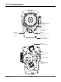
7.4 CHECK POINTS
Port 42
Pressure check port
2nd clutch
Port 46
Pressure check port
Rev. clutch
Port 34a
Pressure check port
Lube
Port 44
Pressure check port
4th. clutch
FRONT VIEW
Plug - Magnetic drain
M22 x 1.5 UNI
Port 16b
From remote filter 1
Port 32
Pressure check port
To cooler
Temperature switch
Port 43
Pressure check port
3rd clutch
REAR VIEW
TE27/32-4-SD
12/2002
7-5
TE 27/32 troubleshooting guide
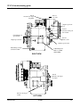
7.4 CHECK POINTS (CONTINUED)
Port 31
Pressure check port
Regulator
Port 11
To cooler
Engine speed sensor
Port 45
Pressure check port
Fwd clutch
Clutch drum gear
speed sensor
Port 42
From cooler
Output speed sensor
Turbine speed sensor
Metric flange for dipstick dia 25.4mm
4 Mounting holes
M20 x 2.5 THD
30mm DEEP
RIGHT VIEW
Port 41
Pressure check port
1st clutch
{
Oil level check port
1⁄4 NPT
TE27/32-4-SD
LEFT VIEW
12/2002
7-6
TE 27/32 troubleshooting guide
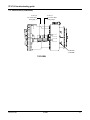
7.4 CHECK POINTS (CONTINUED)
Port 13a
To remote filter
from pump 1
Port 13b
To remote filter
from pump 2
Oil fill hole
3⁄4-14NPTF
TOP VIEW
TE27/32-4-SD
12/2002
7-7
TE 27/32 troubleshooting guide
Checkpoint
Checkpoint
Checkpoint
Checkpoint
Checkpoint
Checkpoint
Checkpoint
Checkpoint
Checkpoint
Checkpoint
Checkpoint
Checkpoint
A
B
C
A ................. VFS 4th/2nd
B ................. VFS FWD
C ................. VFS 3rd/1st
D ................. VFS REV
E ................. Booster REV
F ................. Booster FWD
G................. Booster 4th/2nd
H ................. Booster 3rd/1st
J.................. System pressure (before Total Neutral)
K ................. System pressure (After Total Neutral)
L.................. Pilot pressure
M................. Pressure check range clutches
G
F
H
K
D
E
L
J
M
TE27/32-4-SD
12/2002
7-8
TE 27/32 troubleshooting guide
7.6 SPEED SENSOR - STATIC STANDALONE TEST
In order to be able to sense the currents, a series resistor of e.g. 200 Ω must be used. This resistor is
integrated in the controller, but when the sensor is to be used, it must be connected externally.
The idea is to connect the sensor to an external power source and measure the DC voltage across the
series resistor.
The voltage reading should be either 1.2V (from the 7mA ± 1mA current level) or 2.6 - 3.0V (for the
14mA ± 1mA current level).
If the teeth can be moved slowly, distinct toggling between the two levels should be noticed.
TE27/32-4-SD
12/2002
7-9
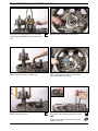
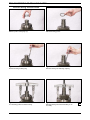
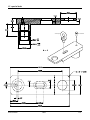
8. SECTIONAL VIEWS & PARTS IDENTIFICATION
TE27/32-4-SD
12/2002
8-1
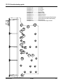
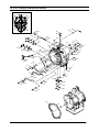
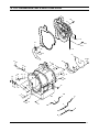
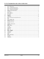
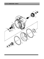
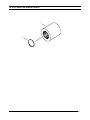
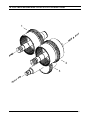
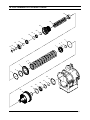
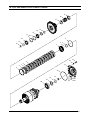
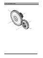
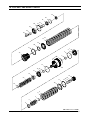
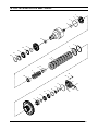
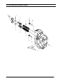
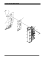
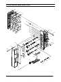
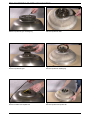
TE 27/32 TORQUE CONVERTER GROUP
TE32
CONVERTER HOUSING GROUP
13
6
7
8
38 37
32
30
33
29
42
43
34
40
35
31
41
14
1
15
21
18
17
19
18
42
43
40
3
41
36
35 13
22
23
37
38
11
18
16
12
45
9
6
10
19
20
44
3
39
39
10
11
19
21
7
12 9
20
3
41
8
40
27
25
26
5
4
43
42
27
28
24
GRP-32011 rev.092002
TE27/32 4 SD
12/2002
8-2
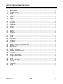
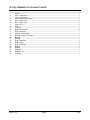
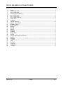
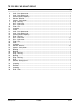
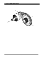
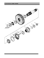
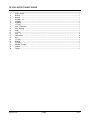
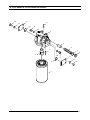
TE 27/32 TORQUE CONVERTER GROUP
Item
1
2
3
4
5
6
7
8
9
10
11
12
13
14
15
16
17
18
19
20
21
22
23
24
25
26
27
28
29
30
31
32
33
34
35
36
37
38
39
40
41
42
43
44
45
Description
Qty
Torque Converter ...............................................................................................................................1
Not Illustrated.....................................................................................................................................1
Plug - Expansion................................................................................................................................3
Plug ...................................................................................................................................................1
“O” Ring .............................................................................................................................................1
Tube ...................................................................................................................................................1
Tube ...................................................................................................................................................1
Tube ...................................................................................................................................................1
Clip.....................................................................................................................................................2
“O” Ring .............................................................................................................................................2
Capscrew...........................................................................................................................................2
Lockwasher........................................................................................................................................2
Tube ...................................................................................................................................................1
Sleeve ................................................................................................................................................1
Sleeve ................................................................................................................................................1
Sleeve ................................................................................................................................................1
Sleeve ................................................................................................................................................1
Washer...............................................................................................................................................3
Capscrew...........................................................................................................................................3
Lockwasher........................................................................................................................................3
Plug....................................................................................................................................................1
Plug....................................................................................................................................................2
“O” Ring .............................................................................................................................................2
Pin - Dowel ........................................................................................................................................2
Capscrew.........................................................................................................................................14
Capscrew...........................................................................................................................................9
Lockwasher......................................................................................................................................23
gasket - Converter to transmission case ...........................................................................................1
Bushing..............................................................................................................................................1
Breather - Air .....................................................................................................................................1
Plug....................................................................................................................................................1
Switch - Temperature .........................................................................................................................1
Adaptor - Temperature switch ............................................................................................................1
Sensor - Speed..................................................................................................................................1
“O” Ring .............................................................................................................................................1
Sensor - Speed 60mm.......................................................................................................................1
Support - Speed sensor.....................................................................................................................2
Capscrew...........................................................................................................................................2
Plug....................................................................................................................................................2
Cover - Split flange ............................................................................................................................3
“O” ring...............................................................................................................................................3
Capscrew.........................................................................................................................................12
Lockwasher......................................................................................................................................12
Plug....................................................................................................................................................1
“O” Ring .............................................................................................................................................1
TE27/32 4 SD
12/2002
8-3
TE32
TRANSMISSION CASE GROUP
TE 27/32 TRANSMISSION CASE & REAR COVER GROUP
10
12
8
22
11
12
8
23
24
25
27
21 20
9
18
28
W
34
21
16 17
20
Y
32
33
6
5
6
5
5
6
14
W
31
6
5
X
35
30
6
5
19
29
26
29
W
X
Y
6
Y
1
4
5
15
3
W
2
X
Y
X
GRP-32021 rev. 092002
TE27/32 4 SD
12/2002
8-4
TE 27/32 TRANSMISSION CASE & REAR COVER GROUP
Item
1
2
3
4
5
6
7
8
9
10
11
12
13
14
15
16
17
18
19
20
21
22
23
24
25
26
27
28
29
30
31
32
33
34
35
Description
Qty
Case - Transmission ......................................................................................................................... 1
Tube - 1st speed clutch pressure ...................................................................................................... 1
Tube - Low shaft rear bearing lube ................................................................................................... 1
Tube - 3rd speed clutch pressure...................................................................................................... 1
Sleeve - Pressure & lubr tube ........................................................................................................... 1
“O” ring.............................................................................................................................................. 6
Cover - Rear ..................................................................................................................................... 1
Plug - Expansion............................................................................................................................... 1
Pin - Dowel ....................................................................................................................................... 2
Capscrew........................................................................................................................................ 37
Capscrew.......................................................................................................................................... 7
Lockwasher..................................................................................................................................... 44
Gasket - Rear cover to transmission case ........................................................................................ 1
Plug................................................................................................................................................... 2
Plug - Magnetic drain........................................................................................................................ 1
Sensor - Speed assy ........................................................................................................................ 1
“O” ring.............................................................................................................................................. 1
Sensor - Speed assy ........................................................................................................................ 1
‘O” ring .............................................................................................................................................. 1
Support - Speed sensor.................................................................................................................... 2
Capscrew.......................................................................................................................................... 2
Tube - Suction ................................................................................................................................... 1
“O” ring.............................................................................................................................................. 1
Lockwasher....................................................................................................................................... 2
Capscrew.......................................................................................................................................... 2
Baffle - Oil ......................................................................................................................................... 1
Cover - Oil baffle ............................................................................................................................... 1
Tube - Oil baffle................................................................................................................................. 3
Lockwasher....................................................................................................................................... 6
Capscrew.......................................................................................................................................... 3
Screw................................................................................................................................................ 3
Cover - Split flange ........................................................................................................................... 1
“O” ring.............................................................................................................................................. 1
Capscrew.......................................................................................................................................... 4
Lockwasher....................................................................................................................................... 4
TE27/32 4 SD
12/2002
8-5
TE32
TURBINE SHAFT GROUP
TE 27/32 TURBINE SHAFT GROUP
2
15
16
14
9
6
7
8
11
12
10
13
3
1
4
5
TE27/32 4 SD
12/2002
8-6
GRP-TE32031 rev 230902
TE 27/32 TURBINE SHAFT GROUP
Item
1
2
3
4
5
6
7
8
9
10
11
12
13
14
15
16
Description
Qty
Bearing - Turbine shaft front ..............................................................................................................1
Bearing - Turbine shaft rear ...............................................................................................................1
Spacer - Front bearing.......................................................................................................................1
Snapring ............................................................................................................................................1
Ring - Piston ......................................................................................................................................1
Stator support assy............................................................................................................................1
Screw - Stator support.......................................................................................................................7
Lockwasher........................................................................................................................................7
Ring - Piston ......................................................................................................................................1
Baffle - Oil ..........................................................................................................................................1
Seal - Oil baffle ..................................................................................................................................1
Ring - Oil baffle seal ..........................................................................................................................1
Ring - Oil baffle retaining ...................................................................................................................1
“O” Ring .............................................................................................................................................1
Snapring ............................................................................................................................................1
Turbine shaft ......................................................................................................................................1
TE27/32 4 SD
12/2002
8-7
TE32
PUMP DRIVE GROUP
TE 27/32 PUMP DRIVE GROUP
2
4
3
9
7
1
8
7
1
10
5
8
11
6
12
7
1
9
8
TE27/32 4 SD
12/2002
GRP-TE32051 rev 290802
8-8
TE 27/32 PUMP DRIVE GROUP
Item
1
2
3
4
5
6
7
8
9
10
11
12
Description
Qty
Support - Pump drive bearing............................................................................................................. 3
Screw - Bearing support ..................................................................................................................... 4
“O” Ring .............................................................................................................................................. 4
Washer................................................................................................................................................ 4
Lockwasher......................................................................................................................................... 2
Screw - Bearing support ..................................................................................................................... 2
Bearing - Pump drive gear.................................................................................................................. 3
Snapring ............................................................................................................................................. 3
Gear - Aux. pump drive ....................................................................................................................... 2
Gear - Charging pump ........................................................................................................................ 1
Gear - Impeller hub............................................................................................................................. 1
Snapring ............................................................................................................................................. 1
TE27/32 4 SD
12/2002
8-9
TE 27/32 ADAPTOR SLEEVE GROUP
1
2
GRP-TE32201 rev.290502
TE27/32 4 SD
12/2002
8-10
TE 27/32 ADAPTOR SLEEVE GROUP
Item
1
2
Description
Qty
Sleeve - Pump drive.......................................................................................................................... 1
Snapring ........................................................................................................................................... 1
TE27/32 4 SD
12/2002
8-11
TE 27/32 WHEEL GROUP
16
17
10
15
14
18
3
6
19
9
1
2
8
5
4
11
20
21
7
24
23
22
12
13
25
TE27/32 4 SD
12/2002
GRP-32061 rev.092002
8-12
TE 27/32 WHEEL GROUP
Item
1
2
3
4
5
6
7
8
9
10
11
12
13
14
15
16
17
18
19
20
21
22
23
24
25
Description
Qty
Member - Reaction ............................................................................................................................1
Snapring ............................................................................................................................................1
Spacer - Reaction member................................................................................................................1
Turbine ...............................................................................................................................................1
Hub - Turbine .....................................................................................................................................1
Snapring ............................................................................................................................................1
Snapring ............................................................................................................................................1
Screw - Turbine hub .........................................................................................................................10
Locktab ..............................................................................................................................................5
Impeller ..............................................................................................................................................1
“O” Ring .............................................................................................................................................1
Screw...............................................................................................................................................32
Lockwasher......................................................................................................................................32
Hub - Impeller ....................................................................................................................................1
“O” Ring .............................................................................................................................................1
Screw.................................................................................................................................................8
Ring - Impeller hub screw backing.....................................................................................................1
Bearing ..............................................................................................................................................1
Snapring ............................................................................................................................................1
Cover - Impeller .................................................................................................................................1
Bearing - Turbine hub ........................................................................................................................1
“O” Ring .............................................................................................................................................1
Spacer ...............................................................................................................................................1
Snapring ............................................................................................................................................1
Hub - Impeller cover ..........................................................................................................................1
TE27/32 4 SD
12/2002
8-13
TE 27/32 FLEX PLATE GROUP
1
2
3
4
TE27/32 4 SD
12/2002
8-14
TE 27/32 DRIVE PLATE GROUP
Item
1
2
3
4
Description
Qty
Assembly - Drive plate and (when used) welded nuts .......................................................................1
Plate - Drive .......................................................................................................................................5
Ring - Backing ...................................................................................................................................1
Capscrew.........................................................................................................................................14
TE27/32 4 SD
12/2002
8-15
TE 27/32 FWD & REV/2ND AND 3TH OR 4TH CLUTCH SHAFT ASSY
1
d
EV
&
2n
R
D
FW
2
3
h
d
3r
t
r4
o
GRP-TE32071 (rev 15nov02)
TE27/32 4 SD
12/2002
8-16
TE 27/32 FWD & REV/2ND AND 3TH OR 4TH CLUTCH SHAFT ASSY
Item
1
2
3
3
Description
Qty
Fwd shaft drum assy .........................................................................................................................1
Rev/2nd shaft drum assy ...................................................................................................................1
3rd shaft drum assy (on 3 speed) ......................................................................................................1
4th shaft drum shaft assy (on 4 speed) .............................................................................................1
TE27/32 4 SD
12/2002
8-17
TE32
FORWARD CLUTCH SHAFT GROUP
TE 27/32 FORWARD CLUTCH SHAFT GROUP
12
10
24
24
14
16
13
15
17
2
18
18
1
5
4
3
6
7
8
9
22
21
20
19
23
25
TE27/32 4 SD
12/2002
8-18
GRP-TE32091 rev240902
TE 27/32 FORWARD CLUTCH SHAFT GROUP
Item
1
2
3
4
5
6
7
8
9
10
11
12
13
14
15
16
17
18
19
20
21
22
23
Description
Qty
Piston.................................................................................................................................................1
Seal - Piston outer .............................................................................................................................1
Seal - Piston inner .............................................................................................................................1
Screen (not sold seperate) ................................................................................................................1
Disc - Clutch inner ...........................................................................................................................11
Disc - Clutch outer ...........................................................................................................................11
Plate - End .........................................................................................................................................1
Seal ...................................................................................................................................................1
Snapring ............................................................................................................................................1
Washer - Belleville ...........................................................................................................................15
Ring - Retaining .................................................................................................................................1
Spacer - Clutch piston .......................................................................................................................1
Bearing - Clutch driven gear ..............................................................................................................1
Bearing ..............................................................................................................................................1
Bearing ..............................................................................................................................................1
Ring - Retaining .................................................................................................................................1
Ring - Piston ......................................................................................................................................2
Ring - Retaining .................................................................................................................................2
Bearing ..............................................................................................................................................1
Spacer ...............................................................................................................................................1
Snapring ............................................................................................................................................1
Retainer - Oil......................................................................................................................................1
Snapring ............................................................................................................................................1
TE27/32 4 SD
12/2002
8-19
TE32
3RD SPEED CLUTCH SHAFT GROUP
TE 27/32 3RD SPEED CLUCTH SHAFT GROUP
12
10
11
14
16
13
17
2
15
19
18
4 3
1
28
6
8
7
5
27
21
9
24
23
22
20
TE27/32 4 SD
12/2002
19
29
26
25
8-20
GRP-TE32101 rev290802
TE 27/32 3RD SPEED CLUCTH SHAFT GROUP
Item
1
2
3
4
5
6
7
8
9
10
11
12
13
14
15
16
17
18
19
20
21
22
23
24
25
26
27
28
29
Description
Qty
Piston................................................................................................................................................. 1
Seal - Piston outer ............................................................................................................................. 1
Seal - Piston inner ............................................................................................................................. 1
Screen (not sold seperate) ................................................................................................................ 1
Disc - Clutch inner ........................................................................................................................... 11
Disc - Clutch outer ........................................................................................................................... 11
Disc - Clutch outer half ...................................................................................................................... 2
Plate - End ......................................................................................................................................... 1
Snapring ............................................................................................................................................ 1
Washer - Belleville ........................................................................................................................... 15
Spacer - Clutch piston ....................................................................................................................... 1
Retainer - Spring ............................................................................................................................... 1
Ring - Retainer................................................................................................................................... 1
Bearing .............................................................................................................................................. 1
Bearing .............................................................................................................................................. 1
Washer............................................................................................................................................... 1
Snapring ............................................................................................................................................ 2
Snapring ............................................................................................................................................ 1
Ring - Piston ...................................................................................................................................... 2
Bearing .............................................................................................................................................. 1
Cap - 3rd speed shaft rear bearing.................................................................................................... 1
Spacer ............................................................................................................................................... 1
Snapring ............................................................................................................................................ 1
“O” Ring ............................................................................................................................................. 1
Plug.................................................................................................................................................... 1
“O” Ring ............................................................................................................................................. 1
Capscrew........................................................................................................................................... 4
Lockwasher........................................................................................................................................ 4
“O” RIng ............................................................................................................................................. 1
TE27/32 4 SD
12/2002
8-21
TE 27/32 3RD SPEED GEAR
1
2
GRP-TE32111 rev290802
TE27/32 4 SD
12/2002
8-22
TE 27/32 3RD SPEED GEAR
Item
1
2
Description
Qty
Gear - 3rd speed.............................................................................................................................. 1
Gear - 3rd speed driven................................................................................................................... 1
TE27/32 4 SD
12/2002
8-23
TE32
REV/2ND
CLUTCH SHAFT GROUP
TE 27/32 REV / 2ND SCHAFT
GROUP
25
26
24
31
30
27
28
29
36
17
18
19
20
21
1
4
2
37
3
D
V
RE
&
2N
13
38
15 14
12
23
32
22
11
33
34
35
10
16
9
8
7
5
6
GRP-TE32121 rev. 240902
TE27/32 4 SD
12/2002
8-24
TE 27/32 REV / 2ND SCHAFT GROUP
Item
1
2
3
4
5
6
7
8
9
10
11
12
13
14
15
16
17
18
19
20
21
22
23
24
25
26
27
28
29
30
31
32
33
34
35
36
Description
Qty
Piston.................................................................................................................................................1
Seal - Clutch piston outer ..................................................................................................................1
Seal - Clutch piston inner...................................................................................................................1
Screen (Not Sold Separate)...............................................................................................................1
Washer - Belleville .............................................................................................................................7
Spacer - Clutch piston .......................................................................................................................1
Ring - Retaining .................................................................................................................................1
Disc - Clutch inner .............................................................................................................................7
Disc - Clutch outer .............................................................................................................................7
Plate - End .........................................................................................................................................1
Snapring ............................................................................................................................................1
Piston.................................................................................................................................................1
Seal - Clutch piston outer ..................................................................................................................1
Seal - Clutch piston inner...................................................................................................................1
Screen (Not Sold Separate)...............................................................................................................1
Ring - Retaining .................................................................................................................................1
Disc - Clutch inner ...........................................................................................................................11
Disc - Clutch outer ...........................................................................................................................11
Plate - End .........................................................................................................................................1
Seal....................................................................................................................................................1
Snapring ............................................................................................................................................1
Washer - Bellevile ............................................................................................................................15
Spacer - Clutch piston .......................................................................................................................1
Bearing ..............................................................................................................................................1
Bearing ..............................................................................................................................................1
Ring - Retaining .................................................................................................................................1
Ring - Retaining .................................................................................................................................1
Bearing ..............................................................................................................................................1
Ring - Retaining .................................................................................................................................1
Ring ...................................................................................................................................................1
Washer - Bearing thrust .....................................................................................................................1
Hub - 2nd Clutch disc ........................................................................................................................1
Snapring ............................................................................................................................................1
Retainer .............................................................................................................................................1
Snapring ............................................................................................................................................1
Ring - Piston ......................................................................................................................................3
TE27/32 4 SD
12/2002
8-25
TE32
TE 27/32 1ST SPEED CLUTCH SHAFT GROUP
1ST SPEED CLUTCH SHAFT GROUP
1
2
4
3
15
8
27
7
26
25
16
28
6
11
5
12
9
10
24
23
21
22
17
31
30
32
19
18
20
29
13
TE27/32 4 SD
14
12/2002
8-26
GRP-TE32131 rev290802
TE 27/32 1ST SPEED CLUTCH SHAFT GROUP
Item
1
2
3
4
5
6
7
8
9
10
11
12
13
14
15
16
17
18
19
20
21
22
23
24
25
26
27
28
29
30
31
32
Description
Qty
Piston..................................................................................................................................................1
Seal - Piston outer ..............................................................................................................................1
Seal - Piston inner ..............................................................................................................................1
Screen (not sold seperate) .................................................................................................................1
Disc - Clutch inner ............................................................................................................................11
Disc - Clutch outer ............................................................................................................................11
Plate - End ..........................................................................................................................................1
Snapring .............................................................................................................................................1
Washer - Belleville ..............................................................................................................................9
Spacer - Clutch piston ........................................................................................................................1
Retainer - Spring ................................................................................................................................1
Ring - Retainer....................................................................................................................................1
Bearing ...............................................................................................................................................1
Washer................................................................................................................................................1
Bearing ...............................................................................................................................................1
Retainer - Oil.......................................................................................................................................1
Ring - Piston .......................................................................................................................................2
Cap - Bearing .....................................................................................................................................1
“O” Ring ..............................................................................................................................................2
Plug.....................................................................................................................................................2
“O” Ring ..............................................................................................................................................2
“O” Ring ..............................................................................................................................................1
Capscrew............................................................................................................................................4
Lockwasher.........................................................................................................................................4
Bearing ...............................................................................................................................................1
Spacer - Bearing.................................................................................................................................1
Snapring .............................................................................................................................................1
Snapring .............................................................................................................................................1
Bearing ...............................................................................................................................................1
Bearing ...............................................................................................................................................1
Spring - Disc .......................................................................................................................................1
Nut ......................................................................................................................................................1
TE27/32 4 SD
12/2002
8-27
TE32
4TH SPEED
CLUTCH
SHAFT GROUP
TE 27/32 4TH SPEED CLUTCH
SHAFT
GROUP
1
4
2
3
15
17
14
16
19
11
13
18
12
9
10
8
6
7
5
6
TE27/32 4 SD
12/2002
8-28
GRP-TE32141 rev 290802
TE 27/32 4TH SPEED CLUTCH SHAFT GROUP
Item
1
2
3
4
5
6
7
8
9
10
11
12
13
14
15
16
17
18
19
Description
Qty
Piston..................................................................................................................................................1
Seal - Piston outer ..............................................................................................................................1
Seal - Piston inner ..............................................................................................................................1
Screen (not sold seperate) .................................................................................................................1
Disc - Clutch inner ............................................................................................................................11
Disc - Clutch outer half .......................................................................................................................2
Disc - Clutch outer ............................................................................................................................11
Plate - End ..........................................................................................................................................1
Snapring .............................................................................................................................................1
Spacer - Clutch piston ........................................................................................................................1
Retainer - Spring ................................................................................................................................1
Spring .................................................................................................................................................1
Ring - Retainer....................................................................................................................................1
Bearing ...............................................................................................................................................1
Snapring .............................................................................................................................................1
Snapring .............................................................................................................................................1
Hub .....................................................................................................................................................1
Snapring .............................................................................................................................................1
Ring - Piston .......................................................................................................................................2
TE27/32 4 SD
12/2002
8-29
TE 27/32 1ST SHAFT GEAR GROUP
2
3r
d
1
GRP-TE32081 rev290802
TE27/32 4 SD
12/2002
8-30
TE 27/32 1ST SHAFT GEAR GROUP
Item
1
2
Description
Qty
Gear - Idler.........................................................................................................................................1
Assy - 1st speed clutch......................................................................................................................1
TE27/32 4 SD
12/2002
8-31
TE32
OUTPUT SHAFT GROUP
TE 27/32 OUTPUT SHAFT GROUP
1
5
5
3
19
4
6
18
17
20
16
8
14
13
10
11
9
12
15
7
2
GRP-TE32161 rev.290502
TE27/32 4 SD
12/2002
8-32
TE 27/32 OUTPUT SHAFT GROUP
Item
1
2
3
4
5
6
7
8
9
10
11
12
13
14
15
16
17
18
19
20
Description
Qty
Shaft - Output .....................................................................................................................................1
Bearing ...............................................................................................................................................1
Bearing ...............................................................................................................................................1
Retainer - Oil.......................................................................................................................................1
Snapring .............................................................................................................................................1
Snapring .............................................................................................................................................1
“O” Ring ..............................................................................................................................................1
Seal - Output oil ..................................................................................................................................1
Cap - Bearing .....................................................................................................................................1
Plug.....................................................................................................................................................1
“O” Ring ..............................................................................................................................................1
Stud ....................................................................................................................................................4
Lockwasher.........................................................................................................................................4
Nut ......................................................................................................................................................4
“O” Ring ..............................................................................................................................................1
Bearing ...............................................................................................................................................1
“O” Ring ..............................................................................................................................................1
Washer - Flange .................................................................................................................................1
Locknut ...............................................................................................................................................1
Flange.................................................................................................................................................1
TE27/32 4 SD
12/2002
8-33
REGULATOR VALVE ASSEMBLY
TE 27/32 REGULATOR VALVE GROUP
6
7
2
9
10
3
7
4
5
9
10
1
8
TE27/32 4 SD
12/2002
8-34
GRP-TE32172 rev. 290502
TE 27/32 REGULATOR VALVE GROUP
Item
1
2
3
4
5
6
7
8
9
10
11
12
13
14
15
16
17
18
19
Description
Qty
Assy - Valve regulator .........................................................................................................................1
Gasket - Valve to converter housing ...................................................................................................1
“O” Ring ..............................................................................................................................................1
Pump - Hydraulic ................................................................................................................................1
Shaft - Gear to pump ..........................................................................................................................1
Snapring .............................................................................................................................................1
Screw..................................................................................................................................................2
Adaptor - Suction tube side ................................................................................................................1
Adaptor - Suction transmission case side...........................................................................................1
Capscrew............................................................................................................................................8
Hose - Suction ....................................................................................................................................1
Clamp - suction...................................................................................................................................2
“O” Ring ..............................................................................................................................................2
Screw..................................................................................................................................................8
Lockwasher.........................................................................................................................................8
Cap - Flange .......................................................................................................................................1
“O” Ring ..............................................................................................................................................1
Capscrew............................................................................................................................................4
Lockwasher.........................................................................................................................................4
TE27/32 4 SD
12/2002
8-35
CONTROL VALVE GROUP
TE 27/32 CONTROL VALVE GROUP
2
1
4
3
TE27/32 4 SD
12/2002
GRP-TE32181 rev 300802
8-36
TE 27/32 CONTROL VALVE GROUP
Item
1
2
3
4
Description
Qty
Assy - Control valve ........................................................................................................................... 1
Gasket ............................................................................................................................................... 1
Screw............................................................................................................................................... 17
Lockwasher...................................................................................................................................... 17
TE27/32 4 SD
12/2002
8-37
TE32
TE 27/32 CONTROL VALVE GROUP (CONT.)
CONTROL VALVE ASSEMBLY
1
3
2
3
23
4
5
34
33
18
29
25
36
26
21
22
24
30
31
32A
19
6
32
20
16
13
27
35
11
15
7
28
8
14
9
7
11
10
11
16
12
15
27
TE27/32 4 SD
12/2002
17
8-38
GRP-TE32182 rev 240902
TE 27/32 CONTROL VALVE GROUP (CONT.)
Item
1
2
3
4
5
6
7
8
9
10
11
12
13
14
15
16
17
18
19
20
21
22
23
24
25
26
27
28
29
30
31
32
33
34
35
36
Description
Qty
Plate - Spacer ....................................................................................................................................1
Plate - Adapter...................................................................................................................................1
Gasket ...............................................................................................................................................2
Plug - Restriction (Not Sold Seperate)...............................................................................................4
Spool (Not Sold Seperate).................................................................................................................1
VFS (Not Sold Seperate) ...................................................................................................................4
Solenoid 24V (Not Sold Seperate).....................................................................................................3
Clamp VFS (Not Sold Seperate)........................................................................................................1
Clamp On / Off (Not Sold Seperate) ..................................................................................................1
Clamp pressure switch ......................................................................................................................1
Screw.................................................................................................................................................9
Harness - Wiring ................................................................................................................................1
Cover - Solenoids ..............................................................................................................................1
Spool (Not Sold Seperate).................................................................................................................2
Spool (Not Sold Seperate).................................................................................................................2
Spring -pilot valve (Not Sold Seperate)..............................................................................................4
Spool - Switch pilot (Not Sold Seperate) ...........................................................................................1
Plate - Separater (Not Sold Seperate)...............................................................................................1
Spool - Pressure reducer (Not Sold Seperate) ..................................................................................1
Spring - Pressure reducer (Not Sold Seperate).................................................................................1
Spool - Pressure check (Not Sold Seperate).....................................................................................4
Spring - Pressure check (Not Sold Seperate)....................................................................................4
Plate - Separater (Not Sold Seperate)...............................................................................................4
Stop (Not Sold Seperate)...................................................................................................................4
Intensifier - Spool (Not Sold Seperate) ..............................................................................................4
Spring (Not Sold Seperate)................................................................................................................4
“O” Ring (Not Sold Seperate).............................................................................................................5
Plug - restriction (Not Sold Seperate) ................................................................................................1
Stop - Spool (Not Sold Seperate) ......................................................................................................4
Spool - Accumulator (Not Sold Seperate)..........................................................................................4
Spring - Accumulator (Not Sold Seperate) ........................................................................................4
Plug..................................................................................................................................................12
Capscrew...........................................................................................................................................4
Lockwasher........................................................................................................................................4
Screw...............................................................................................................................................10
Gasket - Protection cover ..................................................................................................................1
TE27/32 4 SD
12/2002
8-39
TE32
REMOTE FILTER ADAPTOR GROUP
TE 27/32 REMOTE FILTER ADAPTER GROUP
13
11
4
14
12
9
10
3
5
8
4
7
6
2
10
9
11
14
12
13
1
TE27/32 4 SD
12/2002
GRP-TE32191 rev.290502
8-40
TE 27/32 REMOTE FILTER ADAPTOR GROUP
Item
1
2
3
4
5
6
7
8
9
10
11
12
13
14
Description
Qty
Filter................................................................................................................................................... 1
Adapter - Filter ................................................................................................................................... 1
Assy - Filter adapter body.................................................................................................................. 1
Plug.................................................................................................................................................... 1
Spool - Safety valve ........................................................................................................................... 1
Plug.................................................................................................................................................... 1
“O” Ring ............................................................................................................................................. 1
Spring ................................................................................................................................................ 1
Plug.................................................................................................................................................... 2
“O” Ring ............................................................................................................................................. 2
Cap - Flange ...................................................................................................................................... 2
“O” Ring ............................................................................................................................................. 2
Capscrew........................................................................................................................................... 8
Lockwasher........................................................................................................................................ 8
TE27/32 4 SD
12/2002
8-41
9 ASSEMBLY INSTRUCTIONS
TE27/32 4SD
12/2002
9-1
TE 27/32 Assembly instructions
1
3RD
FWD
1
3
1
REV
1ST
4
4TH
2
TE27/32 4 SD
12/2002
9-2
TE 27/32 Assembly instructions
All lead-in chamfers for oil seals, pistonrings and 0-rings must be smooth and free from burrs. Inspect at assembly.
Add some grease to 0-rings before assembly.
Add some grease to piston rings before assembly.
Apply a thin coating of grease between seal lips on lip type seals prior to assembly.
Use only precoated pipe plugs. On uncoated pipe plugs apply a light coat of Loctite© 592
Pump must be filled up with oil prior to assembly.
After assembly of parts using Loctite© there must not be any free or excess material which might enter the oil circuit.
Apply a light coat of Loctite© 262 or 270 to all thru hole stud holes.
1
Teflon seals must be sized prior to assembly. Add some grease to seal diameter of clutch hub before assembly.
2
Fwd/Rev Clutch
TE32
11 seperator plates with outer splines.
11 friction plates (friction material on both sides) with inner splines
Clearance
TE27
Min
Max
6.0mm [0.23in]
6.4mm [0.25in]
10 seperator plates with outer splines.
10 friction plates (friction material on both sides) with inner splines.
Clearance
Min
Max
6.0mm [0.23in]
6.4mm [0.25in]
Use one of the different thickness end plates available to obtain this clearance.
CAUTION
The seperator plates for Fwd and Rev and 1st and 2nd are not the same.
DO NOT MIX PLATES WITH PLATES FROM OTHER CLUTCHES.
3
1st Clutch
TE32
11 seperator plates with outer splines.
11 friction plates (friction material on both sides) with inner splines
Clearance
TE27
Min
Max
4.35mm [0.17in]
4.75mm [0.19in]
10 seperator plates with outer splines.
10 friction plates (friction material on both sides) with inner splines.
Clearance
Min
Max
4.35mm [0.17in]
4.75mm [0.19in]
Use one of the different thickness end plates available to obtain this clearance.
TE27/32 4 SD
12/2002
9-3
TE 27/32 Assembly instructions
4
2nd Clutch
TE32
7 seperator plates with outer splines.
7 friction plates (friction material on both sides) with inner splines
Clearance
TE27
Min
Max
2.75mm [0.10in]
3.15mm [0.12in]
6 seperator plates with outer splines.
6 friction plates (friction material on both sides) with inner splines.
Clearance
Min
Max
2.75mm [0.10in]
3.15mm [0.12in]
Use one of the different thickness end plates available to obtain this clearance.
5
3rd Clutch
TE32
12 seperator plates with outer splines.
11 friction plates (friction material on both sides) with inner splines
2 1-sided friction plates (friction material on one (1) side) with outer splines.
Clearance
TE27
Min
Max
3.5mm [0.14in]
3.9mm [0.16in]
6 seperator plates with outer splines.
6 friction plates (friction material on both sides) with inner splines.
2 1-sided friction plates (friction material on one (1) side) with outer splines.
Clearance
Min
Max
3.5mm [0.14in]
3.9mm [0.16in]
Use one of the different thickness end plates available to obtain this clearance.
6
4th Clutch
TE32
11 seperator plates with outer splines.
10 friction plates (friction material on both sides) with inner splines
2 1-sided friction plates (friction material on one (1) side) with outer splines.
Clearance
TE27
Min
Max
3.1mm [0.12in]
3.5mm [0.14in]
8 seperator plates with outer splines.
7 friction plates (friction material on both sides) with inner splines.
2 1-sided friction plates (friction material on one (1) side) with outer splines.
Clearance
Min
Max
3.1mm [0.12in]
3.5mm [0.14in]
Use one of the different thickness end plates available to obtain this clearance.
TE27/32 4 SD
12/2002
9-4
TE 27/32 Assembly instructions
7
Be sure that shielded and sealed bearings are mounted as shown.
8
Seals must be pressed in perpendicular upon shaft axis from bearing side.
9
Tighten air breather to 31-41 Nm [25-30 Lbs.ft]
10
Tighten nut to 145-160 Nm [107-118 Lbs.ft]
11
Tighten nut to 339-407 Nm [250-300 Lbs.ft]
TE27/32 4 SD
12/2002
9-5
TE 27/32 Assembly instructions
20
21
19
17
18
15
16
2
3
1
5
4
7
6
10
8
12
9
11
13
14
TE27/32 4 SD
12/2002
9-6
TE 27/32 Assembly instructions
Disassembly of the control valve.
Make sure that the aera oround the valve is clean and that no foreign material can enter the control
valve during disassembly. Refer to "Cleaning and Inspection" pages.
Unscrew the 4 hex bolts (marked red with white numbers on the drawing) until you feel that the bolts is
loose. Do not remove the bolt.
Unscrew the 17 other hex bolts until all hex bolts are handloose. You should be able to move the valve
slightly.
Remove 2 hex bolts and replace with aligning studs.
Now remove the remaining loose bolts and remove the valve.
Reinstalling the valve
Using aligning studs install valve and a new gasket. Handtighten all bolts (21 pieces) in the sequence as
on the drawing (page 8-6).
Torque all bolts in the same sequence to 20-25 Nm [14.7-18-5Lbs.ft.]
TE27/32 4 SD
12/2002
9-7
10 DISASSEMBLY AND REASSEMBLY OF TRANSMISSION
TE27/32 4 SD
12/2002
10-1
TE32 DISASSEMBLY OF TRANSMISSION
Figure 1
Front view of the TE32 Transmission.
Figure 4
Remove impeller cover bearing cap and “O” ring.
Figure 2
Remove flex plate mouting bolts and washers.
Figure 5
Remove turbine shaft outer retaining snap ring.
(Caution bearing cover may drop.)
Figure 3
Drive plate and backing ring removed.
TE27/32-4-SD
Figure 6
Remove converter assembly bolts.
12/2002
10-2
TE32 DISASSEMBLY OF TRANSMISSION
Figure 7
Use special tool to lift impeller and cover assembly.
Figure 10
Remove reaction member.
Figure 8
Remove turbine locating ring from turbine shaft.
Figure 11
Remove reaction member spacer.
Figure 9
Remove reaction member retaining snap ring.
Figure 12
Remove oil baffle retaining ring.
TE27/32-4-SD
12/2002
10-3
TE32 DISASSEMBLY OF TRANSMISSION
Figure 13
An impeller removal tool, like the one shown, can
be fabricated to facilitate the removal of the impeller and oil baffle.
Figure 16
Remove pump manifold cap screws.
Figure 14
Remove pump manifold cap screws and hose clips.
Figure 17
Remove pump manifold cap screws.
Figure 15
Remove pump manifold cap screws and hose.
Figure 18
Remove pump drive sleeve.
TE27/32-4-SD
12/2002
10-4
TE32 DISASSEMBLY OF TRANSMISSION
Figure 19
Remove regulator valve cap screws.
Figure 22
Remove pump drive blanking cover plate and
gasket. (If fitted)
Figure 20
Remove regulator valve and gasket.
Figure 23
Remove stator support bolts and lockawashers.
Figure 21
Remove pump drive blanking cover plate bolts. (If
fitted)
Figure 24
Remove stator support.
TE27/32-4-SD
12/2002
10-5
TE32 DISASSEMBLY OF TRANSMISSION
Figure 25
Remove pump drive idler gear bolts.
Figure 28
Remove Pump drive. (Position A).
Figure 26
Remove Pump drive idler gear, bearing and support assy.
Figure 29
Remove Pump drive gear bolts (Position B).
Figure 27
Remove Pump drive gear bolts (Position A).
Figure 30
Remove Pump drive. (Position B).
TE27/32-4-SD
12/2002
10-6
TE32 DISASSEMBLY OF TRANSMISSION
Figure 31
See assembly instructions for disassembly of
control valve.
Figure 34
Remove temperature sensor.
Figure 32
Remove control valve and gasket.
Figure 35
Remove converter housing to transmission case bolts
and washers.
Figure 33
Remove all sensors from converter housing (3).
Figure 36
Support converter housing with chain hoist and strap.
Use a soft hammer to seperate converter housing from
transmission case.
TE27/32-4-SD
12/2002
10-7
TE32 DISASSEMBLY OF TRANSMISSION
Figure 37
Converter assembly removed.
Figure 40
Remove inner retaining ring from 2nd clutch hub .
Note:
REVERSE AND 2NS AND 4TH CLUTCH DRUMWILL REMAIN IN THE CONVERTER HOUSING.
Figure 38
Remove snap ring from 2nd clutch hub (Driven gear).
Figure 41
Remove 2nd clutch hub.
Figure 39
Remove washer from 2nd clutch hub.
Figure 42
Remove snapring from 4th clutch hub and remove hub.
TE27/32-4-SD
12/2002
10-8
TE32 DISASSEMBLY OF TRANSMISSION
Figure 43
Install special tool to prevent 1st shaft from damaging bearing. (See special tool section)
Figure 46
Remove output flange.
Figure 44
Using an impact gun remove output flange nut.
Figure 47
Remove bolts from 3rd clutch shaft rear bearing
cap.
Figure 45
Output flange nut, washer and “O” ring removed.
Figure 48
Remove 3rd clutch shaft rear bearing cap and
“O” ring.
TE27/32-4-SD
12/2002
10-9
TE32 DISASSEMBLY OF TRANSMISSION
Figure 49
Remove 3rd clutch shaft rear bearing cap locating
ring.
Figure 52
Remove nuts from output bearing seal and cover
assy.
Figure 50
Remove 1st clutch shaft rear bearing cap bolts.
Figure 53
Remove output bearing cover assy.
Figure 51
Remove 1st clutch shaft rear bearing cap “O” rings
and spring disc.
Figure 54
Remove output bearing locating ring.
TE27/32-4-SD
12/2002
10-10
TE32 DISASSEMBLY OF TRANSMISSION
Figure 55
Remove transmission rear cover bolts.
Figure 58
Using a hoist, remove rear cover from transmission case. Tap 3rd/1st shaft with a spoft hammer
to assist removal and avoid bending shaft.
Figure 56
Use special tool to remove nut from 1st shaft.
Figure 59
Remove snap ring from 3rd shaft bearing.
See Section 11 “Special Tools”
Figure 57
Remove bearing inner and outer race.
TE27/32-4-SD
Figure 60
Remove spacer.
12/2002
10-11
TE32 DISASSEMBLY OF TRANSMISSION
Figure 61
Use a puller to remove 3rd shaft bearing.
Figure 64
Whilst hoisting shaft and drum remove baffle
plate.
Figure 62
Remove baffle plate bolts (3)
Figure 65
1st shaft drum assy and output shaft assy
removed.
Figure 63
Use special tool as shown and remove 1st shaft
drum assy and output shaft together as shown.
Figure 66
Remove 3rd shaft drum assy.
TE27/32-4-SD
See also figure 67 before hoisting.
12/2002
10-12
TE32 DISASSEMBLY OF TRANSMISSION
Figure 67
Forward drum assy removed showing snapring and
front bearing.(snapring sits under gear and must be
removed before forward drum assy can be hoisted.
Figure 70
Remove 1st shaft drum assy front bearing oil
retainer.
Figure 68
Remove forward drum assy bearing oil retainer.
Figure 71
Remove 1st shaft drum assy front bearing.
Figure 69
Remove 1st shaft drum assy front bearing retaining
ring.
Figure 72
Remove output shaft front bearing snapring.
TE27/32-4-SD
12/2002
10-13
TE32 DISASSEMBLY OF TRANSMISSION
Figure 73
Remove output shaft front bearing oil retainer.
Figure 76
Remove turbine shaft needle roller bearings (2).
Figure 74
Remove output shaft front bearing.
Figure 77
Remove inner baffle plate bolts (3).
Figure 75
Remove turbine shaft bearing snapring.
Figure 78
Remove suction tube assy bolts.
TE27/32-4-SD
12/2002
10-14
TE32 DISASSEMBLY OF TRANSMISSION
Figure 79
Remove suction tube assy and “O” ring.
TE27/32-4-SD
12/2002
10-15
TE32 DISASSEMBLY OF CONVERTER HOUSING
Figure 80
Using external snapring pliers open rev/2nd drum
shaft assy bearing retaining ring and remove shaft
assy.
Figure 83
Remove turbine shaft bearing retaining ring.
Figure 81
Remove 4th drum shaft assy retaining ring.
Figure 84
Using a soft hammer tap turbine shaft and bearing assy from converter housing.
Figure 82
Remove 4th drum shaft assy.
Figure 85
Pry forward shaft bearing from housing as shown.
Note
Check 3 wear sleeves in converter housing and
replace if necessary.
TE27/32-4-SD
12/2002
10-16
TE32 DISASSEMBLY OF REV & 2ND CLUTCH
Reverse being disassembled.
Figure 86
Remove piston sealing rings (3).
Figure 89
Remove bearing spacer.
Figure 87
Remove bearing retaining ring.
Figure 90
Remove clutch gear retainning snapring.
Figure 88
Use a bearing puller to remove bearing.
Figure 91
Remove clutch gear and outer bearing as an
assembly.
TE27/32-4-SD
12/2002
10-17
TE32 DISASSEMBLY OF REV & 2ND CLUTCH
Figure 92
Remove end plate snapring.
Figure 95
Remove inner and outer discs.
Figure 93
Remove end plate and seal assy.
Figure 96
Compress piston return springs and remove
spring retaining snapring.
Caution
Force of springs is 3399N
Figure 94
Remove clutch gear inner bearing.
TE27/32-4-SD
Figure 97
Remove piston return springs.
12/2002
10-18
TE32 DISASSEMBLY OF REV & 2ND CLUTCH
2nd being diassenbled.
Figure 98
Remove piston return springs spacer.
Figure 100
Remove 2nd clutch end plate snapring.
Figure 99
Remove reverse clutch piston.
Figure 101
Remove 2nd clutch end plate.
Figure 102
Remove inner and outer discs.
Note
The steel discs in FWD/REV and 1st & 2nd are
not the same. DO NOT MIX
TE27/32-4-SD
12/2002
10-19
TE32 DISASSEMBLY OF REV & 2ND CLUTCH
Figure 103
Compress return springs and remove snapring.
Figure 106
Remove clutch piston.
Note
Force of disc springs is 2888N
Figure 104
Remove belleville washer disc springs.
Figure 105
Remove clutch piston wear sleeve.
TE27/32-4-SD
12/2002
10-20
TE32 RESASSEMBLY OF REV & 2ND CLUTCH
2nd being reassenbled.
Figure 107
Refer to “Cleaning & Inspection” pages.
Figure 109
Install clutch piston wear sleeve.
The bleed hole in the piston must be clean and free
of any foreign material.
Install clutch piston inner seal.
Note
Ring must be sized before installing in clutch drum.
Sizing is best accomplished by rotating clutch
piston while holding a round object against the new
sealing ring.
Rotate piston until seal ring is flush with outer
diameter of piston.
Figure 110
Install piston return springs.
First spring with large diameter of bevel towards
wear sleeve. See figure 110
Alternate 7 springs.
Wear sleeve
Piston
Shaft
Figure 108
Install clutch piston outer seal.
Figure 111
Note
See figure 105 for sizing.
TE27/32-4-SD
12/2002
10-21
TE32 RESASSEMBLY OF REV & 2ND CLUTCH
Figure 112
Compress spring and install spring retaining snapring.
Figure 115
Install end plate retaining ring.
Note
Be sure ring is in full position in groove.
Figure 113
Install clutch pack discs into drum. Start with one
steel disc against piston. Alternate friction and steel
discs until proper amount are installed. Last disc is
friction disc.
Figure 114
Install end plate.
TE27/32-4-SD
12/2002
10-22
TE32 RESASSEMBLY OF REV & 2ND CLUTCH
2nd being reassenbled
Figure 116
Refer to “Cleaning & Inspection” pages.
Figure 119
Install clutch piston wear sleeve.
The bleed hole in the piston must be clean and free
of any foreign material.
Install clutch piston inner seal. Size as described in
figure 106.
Figure 117
Install clutch piston outer seal.
Note
Figure 120
Install clutch piston return disc springs. First
spring with large diameter of bevel towrds wear
sleeve. Alternate fifteen (15) springs.
See figure 107 for sizing.
See figure 121.
Piston
Wear sleeve
Shaft
Figure 118
Install clutch piston in drum as shown.
Figure 121
Use caution as not to damage inner and outer
piston sealing rings.
TE27/32-4-SD
12/2002
10-23
TE32 RESASSEMBLY OF REV & 2ND CLUTCH
Figure 122
Compress spring and install retaining ring.
Figure 125
Install install end plate in drum and fit end plate
retaining ring.
Note
Make sure ring is in full position in groove.
Figure 123
Install one (1) steel disc into drum. Alternate friction and steel discs until proper amount of discs is
installed. First and last disc are steel.
Figure 126
Warm inner bearing to 120° C [248° F] and install
bearing on shaft.
Figure 124
Install new seal in end plate.
Figure 127
Install two (2) bearing retaining rings in clutch gear
and install clutch gear and hub into clutch drum.
Align splines on clutch hub with internal teeth of
frintion discs. Tap gear into position. Do not force
this operation. Gear splines must be aligned with
internal teeth of all friction discs.
TE27/32-4-SD
12/2002
10-24
TE32 RESASSEMBLY OF REV & 2ND CLUTCH
Figure 128
Warm outer bearing to 120° C [248° F] and install
bearing on shaft.
Figure 131
Warm outer bearing to 120° C [248° F] and install
bearing on shaft with groove down as shown.
Figure 129
Install bearing snapring.
Figure 132
Install bearing snapring.
Figure 130
Install outer bearing thrust washer.
Figure 133
Install three (3) clutch shaft piston rings.
TE27/32-4-SD
12/2002
10-25
TE32 DISASSEMBLY OF FWD CLUTCH
Figure 134
Remove bearing snap ring.
Figure 137
Remove Remove large snapring from shaft.
Figure 135
Remove bearing spacer.
Figure 138
Remove two (2) piston seal rings.
Figure 136
Remove bearing.
Figure 139
Remove bearing snap ring.
TE27/32-4-SD
12/2002
10-26
TE32 DISASSEMBLY OF FWD CLUTCH
Figure 140
Remove bearing inner race.
Figure 143
Remove end plate retaining ring.
Figure 141
Remove retaining ring.
Figure 144
Remove end plate.
Figure 142
Use a puller and remove clutch gear and outer
bearing.
Figure 145
Remove inner and outer clutch discs.
TE27/32-4-SD
12/2002
10-27
TE32 DISASSEMBLY OF FWD CLUTCH
Figure 146
Remove inner bearing.
Figure 149
Remove clutch piston wear sleeve.
Figure 147
Compress return spring and remove snapring.
Figure 150
Remove clutch piston.
Note
Force of disc spring is 3381N
Figure 148
Remove return spring pack.
TE27/32-4-SD
12/2002
10-28
TE32 REASSEMBLY OF FWD CLUTCH
Figure 151
Refer to “Cleaning & Inspection” pages.
Figure 154
Install clutch piston return disc springs. First
spring with large diameter of bevel towards wear
sleeve. Alternate fifteen (15) springs.
The bleed hole in the piston must be clean and free
of any foreign material.
See figure 155
Install clutch piston inner seal.
See note figure 59.
Piston
Wear sleeve
Shaft
Figure 152
Install clutch piston outer seal.
Figure 155
See note figure 59.
Figure 153
Install clutch piston wear sleeve.
TE27/32-4-SD
Figure 156
Compress spring and install snapring.
12/2002
10-29
TE32 REASSEMBLY OF FWD CLUTCH
Figure 160
Warm outer bearing to 120° C [248° F] and install
bearing on shaft.
Figure 157
Install one steel disc. Alternate friction and steel
disc until proper amount of discs is installed.
First and last disc are steel.
Figure 161
Install two (2) bearing locating rings in clutch gear and
install clutch gear into clutch drum. Align splines on clutch
hub with internal teeth of steel discs. Tap gear into position.
Figure 158
Install new seal in end plate and install plate.
See note figure 127
Figure 159
Install end plate retaining ring.
TE27/32-4-SD
Figure 162
Warm outer bearing to 120° C [248° F] and install
bearing on shaft.
12/2002
10-30
TE32 REASSEMBLY OF FWD CLUTCH
Figure 163
Install bearing snapring.
Figure 166
Install two (2) piston rings.
Figure 164
Install bearing inner race.
Figure 167
Install retaining ring over shaft before fitting bearing.
Figure 165
Install bearing retainig ring.
Figure 168
Warm outer bearing to 120° C [248° F] and install
bearing on shaft with groove down as shown.
TE27/32-4-SD
12/2002
10-31
TE32 REASSEMBLY OF FWD CLUTCH
Figure 169
Install bearing spacer.
Figure 170
Install snapring.
TE27/32-4-SD
12/2002
10-32
TE32 DISASSEMBLY OF 3RD CLUTCH
Figure 171
Remove one (1) piston ring.
Figure 174
Remove spacer.
Figure 172
Remove clutch gear bearing retaining ring.
Figure 175
Remove end plate retainnig ring.
Figure 173
Remove 3rd clutch driven gear and bearing.
Figure 176
Remove end plate.
TE27/32-4-SD
12/2002
10-33
TE32 DISASSEMBLY OF 3RD CLUTCH
Figure 177
Remove inner and outer discs.
Figure 180
Remove spring retainer.
Figure 178
Compress spring and remove snapring.
Figure 181
Remove clutch piston.
Figure 179
Remove spring and spring retainer.
TE27/32-4-SD
12/2002
10-34
TE32 REASSEMBLY OF 3RD CLUTCH
Figure 182
Refer to “Cleaning & Inspection” pages.
Figure 185
Install piston return spring.
The bleed hole in the piston must be clean and free
of any foreign material.
Install clutch piston inner seal.
See note figure 59.
Figure 183
Install clutch piston outer seal. And install piston
into drum.
Figure 186
Install piston return spring retainer.
See note figure 59.
Figure 184
Install piston spacer.
TE27/32-4-SD
Figure 187
Compress spring and Install piston return spring
retainer retaining ring.
12/2002
10-35
TE32 REASSEMBLY OF 3RD CLUTCH
Figure 188
Install half disc (friction material on one side) with
steel side down.
Figure 191
Install clutch disc end plate.
Figure 189
Install one steel disc. Alternate friction and steel
disc until proper amount of discs are installed. First
and last disc are steel.
Figure 192
Install clutch disc end plate retaing ring.
Figure 190
Install half disc (friction material on one side) with
steel side up.
Figure 193
Install spacer.
TE27/32-4-SD
12/2002
10-36
TE32 REASSEMBLY OF 3RD CLUTCH
Figure 194
Heat gear and bearing assy to 120° C [248° F] and
install gear. Align splines on clutch hub gear with
internal teeth of friction discs. Do not force this
operation. Gear splines must be in full position
with internal teeth of all inner discs.
Figure 197
Install piston ring.
Figure 195
Install bearing retaining ring.
Figure 196
Install piston ring.
TE27/32-4-SD
12/2002
10-37
TE32 DISASSEMBLY OF 4TH CLUTCH
Figure 198
Remove piston sealing rings.
Figure 201
Remove retaining snapring from shaft.
Figure 199
Remove bearing snap ring.
Figure 202
Remove end plate retaining ring.
Figure 200
Using a puller as shown, remove bearing from
shaft.
Figure 203
Remove end plate.
TE27/32-4-SD
12/2002
10-38
TE32 DISASSEMBLY OF 4TH CLUTCH
Figure 204
Remove inner and outer clutch plates.
Figure 207
Remove spacer.
Figure 205
Remove Compress spring and remove snapring.
Figure 208
Remove clutch piston.
Figure 206
Remove spring retainer and spring.
TE27/32-4-SD
12/2002
10-39
TE32 REASSEMBLY OF 4TH CLUTCH
Figure 209
Refer to “Cleaning & Inspection” pages.
Figure 212
Install spring and spring retainer.
The bleed hole in the piston must be clean and free
of any foreign material.
Install clutch piston inner seal.
See note figure 59.
Figure 210
Install clutch piston outer seal. And install piston
into drum.
Figure 213
Compress spring and install spring retaing
snapring.
See note figure 59.
Figure 211
Install spacer.
TE27/32-4-SD
Figure 214
Install one (1) half disc (friction material on one
(1) side) steel side down.
12/2002
10-40
TE32 REASSEMBLY OF 4TH CLUTCH
Figure 215
Install one (1) friction disc. Alternate steel and
froction plates until proper amount of discs are
installed.
Figure 218
Install end plate retaining ring.
Figure 216
Install one (1) half disc (friction material on one (1)
side) steel side up.
Figure 219
Install snapring over shaft (to be used when
installing drum/shaft in casing.)
Figure 217
Install end plate.
Figure 220
Warm bearing to 120°C [248° F] and install on
shaft.
TE27/32-4-SD
12/2002
10-41
TE32 REASSEMBLY OF 4TH CLUTCH
Figure 221
Install bearing retaining snap ring.
Figure 222
Install piston rings.
TE27/32-4-SD
12/2002
10-42
TE32 DISASSEMBLY OF 1ST CLUTCH
Figure 223
Remove piston rings.
Figure 226
Remove end plate retaining ring.
Figure 224
Using a puller remove gear, bearing, bearing outer
race and spacer as an assembly.
Figure 227
Remove end plate.
Figure 225
Remove bearing spacer.
Figure 228
Remove inner and outer clutch plates.
TE27/32-4-SD
12/2002
10-43
TE32 DISASSEMBLY OF 1ST CLUTCH
Figure 229
Using a bearing puller remove lower hub taper
roller bearing from shaft.
Figure 232
Remove piston return spring pack.
Figure 230
Compress piston return spring and remove piston
return spring snapring.
Figure 233
Remove piston return spring spacer.
Figure 231
Remove spring retaining ring.
Figure 234
Remove clutch piston.
TE27/32-4-SD
12/2002
10-44
TE32 DISASSEMBLY OF 1ST CLUTCH
Figure 235
Turn shaft and remove outer bearing race from
shaft.
Figure 238
Remove gear.
Figure 236
Remove snapring shield.
Figure 237
Remove snapring.
TE27/32-4-SD
12/2002
10-45
TE32 REASSEMBLY OF 1ST CLUTCH
Figure 239
Refer to “Cleaning & Inspection” pages.
Figure 242
Install clutch piston return disc springs. First
spring with large diameter of bevel towards wear
sleeve. Alternate nine (9) springs.
The bleed hole in the piston must be clean and free
of any foreign material.
See figure 243
Install clutch piston inner seal.
See note figure 59.
PISTON
SPACER
SHAFT
Figure 240
Install clutch piston outer seal. And install piston
into drum.
Figure 243
See note figure 59.
Figure 241
Install wear sleeve.
Figure 244
Install clutch piston return disc springretainer.
Make sure return spring retainer is fitted with
stepped groove up.
TE27/32-4-SD
12/2002
10-46
TE32 REASSEMBLY OF 1ST CLUTCH
Figure 245
Compress return spring and install return spring
retainer. Make sure retaining ring is in full contact
in groove.
Figure 248
Install end plate retaining snapring.
Figure 246
Install one (1) friction disc. Alternate steel and
froction plates until proper amount of discs are
installed.
Figure 249
Warm taper bearing to 120° C [248° F] and
install on shaft.
Figure 247
Install end plate.
Figure 250
Install bearing spacer.
TE27/32-4-SD
12/2002
10-47
TE32 REASSEMBLY OF 1ST CLUTCH
Figure 251
Install clutch driven gear and hub assembly.
Figure 254
Warm bearing race to 120° C [248° F] and install
on shaft.
Align splines on clutch gear hub with internal
splines of friction discs. Do not force this operation. Gear splines must be in full position with
internal teeth of all inner discs.
Figure 252
Warm taper bearing to 120° C [248° F] and install
on shaft.
Figure 255
Install piston sealing rings.
Figure 253
Install bearing spacer.
Figure 256
Turn shaft and install gear.
TE27/32-4-SD
12/2002
10-48
TE32 REASSEMBLY OF 1ST CLUTCH
Figure 257
Install gear retaing snap ring.
Figure 258
Install gear retaing snap ring shield.
Figure 259
Warm bearing race to 120° C [248° F] and install
on shaft.
TE27/32-4-SD
12/2002
10-49
TE32 DISASSEMBLY OF OUTPUT SHAFT
Figure 260
Using a puller remove bearing from shaft.
Figure 263
Remove gear.
Figure 261
Turn shaft and Using a puller remove bearing inner
race from shaft.
Figure 264
Remove snapring.
Figure 262
Remove snapring.
TE27/32-4-SD
12/2002
10-50
TE32 REASSEMBLY OF OUTPUT SHAFT
Figure 265
Install snapring.
Figure 268
Heat bearing inner race to 120°C [248°F] and
install on shaft.
Figure 266
Install gear.
Figure 269
Heat bearing inner race to 120°C [248°F] and
install on shaft.
Figure 267
Install snapring.
TE27/32-4-SD
12/2002
10-51
TE32 DISASSEMBLY OF TURBINE SHAFT
Figure 270
Remove piston sealing ring.
Figure 273
Use a hydraulic press to remove bearing.
Figure 271
Remove bearing retaining ring.
Figure 272
Remove spacer.
TE27/32-4-SD
12/2002
10-52
TE32 REASSEMBLY OF TURBINE SHAFT
Figure 274
Warm bearing to 120°C [248°F] and install on
shaft. Note that retaining ring groove is up.
Figure 277
Install piston sealing ring.
Figure 275
Install spacer.
Figure 276
Install snapring.
TE27/32-4-SD
12/2002
10-53
TE32 DISASSEMBLY OF IMPELLOR AND BAFFLE
Figure 278
Remove impellor hub gear retaining ring.
Figure 281
Remove impellor hub bolts.
Figure 279
Remove impellor hub gear.
Figure 282
Remove impellor hub backing ring.
Figure 280
Remove oil baffle from impellor hub.
Figure 283
Remove impellor from impellor hub.
TE27/32-4-SD
12/2002
10-54
TE32 DISASSEMBLY OF IMPELLOR AND BAFFLE
Figure 284
Remove impellor from impellor hub.
Figure 285
Remove impellor hub bearing retaining ring.
Figure 286
Remove impellor hub bearing.
TE27/32-4-SD
12/2002
10-55
TE32 DISASSEMBLY OF IMPELLOR AND BAFFLE
Figure 287
Install impellor hub bearing.
Figure 290
Position impellor hub O-ring on hub.
Figure 288
Install impellor hub bearing retaining ring.
Figure 291
Position impellor hub bolt backing ring.
Figure 289
Position new impellor hub O-ring on hub.
TE27/32-4-SD
12/2002
10-56
TE32 REASSEMBLY OF IMPELLOR AND BAFFLE
Figure 292
Make sure that hub mounting surface and tapped
holes are cleaned with solvent. Install self locking
screws and tighten to 58 - 64 Ft.lns [79-87 Nm]
Figure 294
Install impeller hub gear.
Note:
Assembly of hub must be completed within a fifteen
minute period from start of screw installation. The
special screw is to be used for one (1) installation
only. If the screw is removed for any reason, it must
be replaced. The epoxy left in the hub holes must
be removed with the proper tap and the hole must
be cleaned with solvent. Dry the holes thoroughly
and use a new screw for reinstallation.
Figure 295
Install impeller hub gear retaining ring.
Figure 293
Apply a light coat of Loctite© 638 to the outer diameter of the oil baffle oil seal, press oil seal in oil
baffle wit lip of seal down. Install oil baffle O-ring.
TE27/32-4-SD
12/2002
10-57
TE32 DISASSEMBLY OF IMPELLOR COVER AND TURBINE ASSEMBLY
Figure 296
Remove turbine hub front bearing retaining ring.
Figure 299
Remove turbine hub bolts and lock tabs.
Figure 297
Remove turbine hub front bearing washer.
Figure 298
Tap turbine hub from impeller cover.
TE27/32-4-SD
12/2002
10-58
TE32 REASSEMBLY OF IMPELLOR COVER AND TURBINE ASSEMBLY
Figure 300
Align holes in turbine and turbine hub. Position lock
tabs and install bolts. Tighten bolts to specified
torque ‘See torque chart). Bend a corner of the lock
tab over a flat of the bolt heads. See figure 301.
Figure 303
Install washer.
Figure 301
Figure 304
Install bearing retaing snapring.
Figure 302
Center impeller cover over turbine hub. Install
impeller cover bearing in impeller cover and over
turbine hub. Tap bearing into place.
TE27/32-4-SD
12/2002
10-59
TE32 DISASSEMBLY & REASSEMBLY OF PUMP DRIVE GEAR
Figure 305
Remove snapring.
Figure 308
Press support into bearing and install assembly
into gear.
Figure 306
Remove bearing.
Figure 309
Install bearing snapring.
Figure 307
Remove support.
TE27/32-4-SD
12/2002
10-60
TE32 REASSEMBLY OF CONVERTER HOUSING
A
B
Figure 310
Install outer pump drive gear assemblies (Left and
right). Put new 0-rings (4) on bolts, install bolts and
tighten to specified torque (See torque chart).
Figure 313
From the rear of the housing tap turbine shaft and bearing in converter housing. Tap shaft until gear shoulders is
against converter housing.
Figure 311
Install center pump drive gear assembly. Tighten bolts to
specified torque.
Figure 314
From the front of the housing, install turbine shaft bearing
locating ring. Tap shaft until ring is in full position in groove.
Figure 312
Install 4th speed outer roller bearing in converter housing.
Figure 315
Install new O-ring on stator support. Position stator support
on turbine shaft. Turn stator support to clear pump drive
gear. Align support holes with converter housing.
TE27/32-4-SD
12/2002
10-61
TE32 REASSEMBLY OF CONVERTER HOUSING
Figure 316
Install stator support nolts and washers and tighten bolts to
specified torque.
Figure 319
Install 4th shaft and drum assembly snap ring.
Figure 317
Spread ears on snapring and install 2nd/Rev clutch drum
assembly into converter housing.
Figure 320
Install needle roller bearings on 2nd/Rev and 4th shafts.
Figure 318
Install 4th shaft and drum assy into converter housing.
TE27/32-4-SD
12/2002
10-62
TE32 REASSEMBLY OF TRANSMISSION
Figure 321
Install suction tube and “O” ring into transmission
case.
Figure 324
Install output shaft bearing and oil retainer. See
figure 325.
TRANSMISSION
CASE
SHAFT
OIL RETAINER
BEARING
Figure 322
Install suction tube bolts and washers and tighten
to specified torque. (See torque chart)
Figure 325
Figure 323
Install oil baffle plate and spacers (3). Add Loctite®
262 to bolts threads and install from other side
of transmission. Torque to specified torque. (See
torque chart)
Figure 326
Install output shaft and oil retainer snapring.
TE27/32-4-SD
12/2002
10-63
TE32 REASSEMBLY OF TRANSMISSION
Figure 327
Install 1st clutch shaft bearing.
Figure 330
Install 1st clutch shaft bearing snap ring.
Figure 328
Install 1st clutch shaft oil retainer.
Figure 331
Install fwd shaft bearing oil retainer.
See figure 328.
See figure 332.
TRANSMISSION
CASE
SHAFT
TRANSMISSION
CASE
SHAFT
OIL RETAINER
OIL RETAINER
BEARING
BEARING
Figure 329
TE27/32-4-SD
Figure 332
12/2002
10-64
TE32 REASSEMBLY OF TRANSMISSION
Figure 333
Install 3rd clutch and drum as an assembly.
Figure 336
Warm 3rd shaft bearing to 120° C [248° F] and
istall on shaft with snap ring groove up.
Figure 334
Install special tool as shown.
Figure 337
Install bearing spacer
Figure 335
Using special tool, install output shaft and 1st
clutch assembly.
Figure 338
Install bearing snapring.
TE27/32-4-SD
12/2002
10-65
TE32 REASSEMBLY OF TRANSMISSION
Figure 339
Install transmission case to rear cover new gasket
and “O” rings (3).
Figure 342
Raise output shaft slightly and install bearing
retaining ring.
Figure 340
Install 2 aligning studs and install transmission
case rear cover.
Figure 343
Raise 3rd shaft slightly and install bearing retaining ring.
Figure 341
Install rear cover to transmission case bolts and
tighten to specified torque.
Figure 344
Install ball bearing assembly onto 1st shaft.
TE27/32-4-SD
12/2002
10-66
TE32 REASSEMBLY OF TRANSMISSION
Figure 345
Install lock nut on 1st shaft.
Figure 348
Install nuts and lockwashers to bearing cap and
tighten to specified torque. See torque chart.
Figure 346
Using special tool torque lock nut to 145-160 Nm
[107-118 Lbs.ft].
Figure 349
Fit new seal and “O” ring to 3rd shaft bearing cap
and install cap.
Figure 347
Fit new seal and “O” ring to output shaft bearing
cap and install cap.
Figure 350
Install nuts and lockwashers to bearing cap and
tighten to specified torque. See torque chart.
TE27/32-4-SD
12/2002
10-67
TE32 REASSEMBLY OF TRANSMISSION
Figure 351
Install 1st shaft bearing cap with new “O” rings (3)
and spring disc.
Figure 354
Install output flange “O” ring, washer and nut.
Figure 352
Install bolts and lockwashers to bearing cap and
tighten to specified torque. See torque chart.
Figure 355
Tighten output flange nut to 339-407 Nm [250300 Lbs.ft]
Figure 353
Install new oil seal on output flange and install
flange on shaft.
Figure 356
Install 4th clutch hub and snapring.
TE27/32-4-SD
12/2002
10-68
TE32 REASSEMBLY OF TRANSMISSION
Figure 357
Install 2nd clutch hub.
Figure 360
Install alignment studs and position converter
housing assembly on on studs.
Note:
Turning output shaft will assist in aligning clutch
hubs with clutch assembly.
Install converter housing to transmission housing
bolts and lockwashers and tighten to specified
torque. See torque chart.
Caution
Bolts are not to be used to pull converter and
transmission housing together.
Figure 358
Install 2nd clutch hub retaining ring, spacer and
snapring.
Figure 359
Install new converter housing to transmission case
gasket and new “O” rings (3).
TE27/32-4-SD
Figure 361
Install aligning studs and install new valve gasket.
12/2002
10-69
TE32 REASSEMBLY OF TRANSMISSION
Figure 362
Install control valve. See assembly instructions.
Figure 365
Install pump drive shaft.
Figure 363
Install regulator valve and new gasket to converter
housing.
Figure 366
With new “O” ring in place, install pump assembly.
Figure 364
Install capscrews and torque to specified torque.
See torque chart.
Figure 367
Install pump capscrews and lockwashers and
tighten to specified torque. See torque chart.
TE27/32-4-SD
12/2002
10-70
TE32 REASSEMBLY OF TRANSMISSION
Figure 368
Install pump manifold and hose, fitting new “O”
rings if required.
Figure 371
Install pump drive shipping covers (if fitted) and
install bolts and lockwashers. Tighten to specified
torque. See torque chart.
Figure 369
Install capscrews and lockwashers and torque to
specified torque. See torque chart.
Figure 372
Install impeller and oil baffle assembly.
Figure 370
Tighten clips on suction hose.
Figure 373
Install impeller hub bearing inner race.
TE27/32-4-SD
12/2002
10-71
TE32 REASSEMBLY OF TRANSMISSION
Figure 374
Using a soft drive tap oil baffle down to seat correctly.
Figure 377
Install reaction member with thin side of blades
inwards to impeller.
Figure 375
Install oil baffle retaing ring. Make sure retaining
ring is in full contact in grrove.
Figure 378
Install reaction member snapring.
Figure 376
Install reaction member spacer.
Figure 379
Install turbine hub rear retaining snapring on
shaft.
TE27/32-4-SD
12/2002
10-72
TE32 REASSEMBLY OF TRANSMISSION
Figure 380
Position new “O” ring on impeller cover and install
cover and turbine assembly on shaft.
Figure 383
Install new “O” ring on bearing cap and install
cap.
Figure 381
Install impeller cover bolts and lockwashers and
tighten to specified torque. See torque chart.
Figure 384
Position flex plates on turbine cover.
Figure 382
Install turbine retaining snapring.
Figure 385
Position flex plates backing ring.
TE27/32-4-SD
12/2002
10-73
TE32 REASSEMBLY OF TRANSMISSION
Figure 386
Install flex plate mounting bolts and lockwashers
and tighten to specified torque.
Figure 387
Install speed sensors (3).
Figure 388
Install temperature sensor.
TE27/32-4-SD
12/2002
10-74
11. SPECIAL TOOLS
TE27/32-4-SD
12/02
11-1
TE32KALIBER1
11. special tools
TE27/32-4-SD
12/02
11-2
11. special tools
61M tlobeyE
TE27/32-4-SD
12/02
04 x 01M tloB
11-3
Bolt .4375-14 UNC-3B X 20
both sides
11. special tools
TE27/32-4-SD
12/02
11-4
11. special tools
Ø 63
-0
Ø 61 +0.1
10
45
4 SLOTS
6 +0- 0.1
TE27/32-4-SD
12/02
11-5
APPLICATION POLICY
Capability ratings, features and specifications vary depending upon the model type of service.
Application approvals must be obtained from Spicer Off-Highway Products Division. We reserve the right to
change or modify our product specifications, configurations or dimensions at any time without prior notice.
SPICER OFF-HIGHWAY PRODUCTS DIVISION
Ten Briele 3
B-8200 Brugge, Belgium