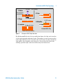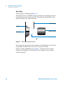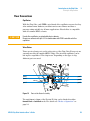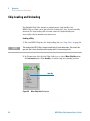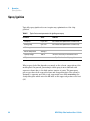
1
Agilent 1260 Infinity HPLC-Chip Cube Interface (G4240A ) User Manual Notices © Agilent Technologies, Inc. 2010, 2012 Warranty No part of this manual may be reproduced in any form or by any means (including electronic storage and retrieval or translation into a foreign language) without prior agreement and written consent from Agilent Technologies, Inc. as governed by United States and international copyright laws. The material contained in this document is provided “as is,” and is subject to being changed, without notice, in future editions. Further, to the maximum extent permitted by applicable law, Agilent disclaims all warranties, either express or implied, with regard to this manual and any information contained herein, including but not limited to the implied warranties of merchantability and fitness for a particular purpose. Agilent shall not be liable for errors or for incidental or consequential damages in connection with the furnishing, use, or performance of this document or of any information contained herein. Should Agilent and the user have a separate written agreement with warranty terms covering the material in this document that conflict with these terms, the warranty terms in the separate agreement shall control. Manual Part Number G4240-90006 Rev. B Edition 05/2012 Printed in Germany Agilent Technologies Hewlett-Packard-Strasse 8 76337 Waldbronn defined in FAR 52.227-19(c)(1-2) (June 1987). U.S. Government users will receive no greater than Limited Rights as defined in FAR 52.227-14 (June 1987) or DFAR 252.227-7015 (b)(2) (November 1995), as applicable in any technical data. Safety Notices CAUTION A CAUTION notice denotes a hazard. It calls attention to an operating procedure, practice, or the like that, if not correctly performed or adhered to, could result in damage to the product or loss of important data. Do not proceed beyond a CAUTION notice until the indicated conditions are fully understood and met. Technology Licenses The hardware and/or software described in this document are furnished under a license and may be used or copied only in accordance with the terms of such license. Restricted Rights Legend If software is for use in the performance of a U.S. Government prime contract or subcontract, Software is delivered and licensed as “Commercial computer software” as defined in DFAR 252.227-7014 (June 1995), or as a “commercial item” as defined in FAR 2.101(a) or as “Restricted computer software” as defined in FAR 52.227-19 (June 1987) or any equivalent agency regulation or contract clause. Use, duplication or disclosure of Software is subject to Agilent Technologies’ standard commercial license terms, and non-DOD Departments and Agencies of the U.S. Government will receive no greater than Restricted Rights as WA R N I N G A WARNING notice denotes a hazard. It calls attention to an operating procedure, practice, or the like that, if not correctly performed or adhered to, could result in personal injury or death. Do not proceed beyond a WARNING notice until the indicated conditions are fully understood and met. HPLC-Chip Cube Interface User’s Guide In This Guide… This manual gives an introduction to HPLC-Chip technology and explains how to install, maintain and troubleshoot you HPLC-Chip Cube. 1 Introduction to HPLC-Chip Technology 2 Introduction to the Chip Cube 3 Site Preparation 4 Installation 5 Operation 6 Maintenance Procedures 7 Consumables and Maintenance Parts Appendix A Appendix A Safety Information HPLC-Chip Cube Interface User’s Guide 3 4 HPLC-Chip Cube Interface User’s Guide Contents Content 1 Introduction to HPLC-Chip Technology Overview 9 10 Chip Types 13 The MS Calibration and Diagnosis Chip, Part No. G4240-61001 The Protein ID Chip, Part No. G4240-62001 14 Modes of Operation 14 More Chips 18 2 Introduction to the Chip Cube Intended Use 13 19 20 Introduction 21 Power Switch 22 Safety Features 23 Main Assemblies 24 Principle of Operation Flow Connections 3 Site Preparation 26 29 31 Site Requirements for the G4240A Chip Cube 32 Power Considerations 32 Bench Space 32 Environment 33 Sound Emission 34 Specifications of the G4240A HPLC-Chip Cube 34 4 Installation 37 Unpacking the Agilent G4240A HPLC-Chip MS Interface Damaged Packaging 38 Delivery Checklist 38 HPLC-Chip Cube Interface User’s Guide 38 5 Contents Accessory Kit 40 System Setup Considerations Single Stack Setup 43 Twin Stacks 45 5 42 Preparation of Existing Systems 47 Chip Cube Hardware Installation 49 Operation 53 Chip Loading and Unloading 54 Configuration 55 Configure Loading Pump and Analytical Pump 55 Injection Flush Volume 56 Injector Flush Volume and the use of Injector Programs Operational Parameters 57 60 Setting up Chip Cube Parameters 61 Chip (Valve Positions / Tip) 61 Time 62 Time Table 63 Instrument Actuals 63 Chip Details Screen 64 Spray Ignition 66 Conditions to avoid 6 69 Maintenance Procedures Maintenance Overview Replacing Capillaries 71 72 73 Cleaning the Valve Rotors (quick procedure) Updating the Chip Cube Firmware 6 76 79 HPLC-Chip Cube Interface User’s Guide Contents 7 Consumables and Maintenance Parts HPLC-Chips Capillaries Fittings 81 82 83 84 Infusion Spare Parts 85 Valve Rotor Cleaning Tools and Replacement Parts 8 Appendix A Safety Information 86 87 Safety Information 88 Power Cords 88 Operation 89 Safety Symbols 90 Chemical and Biological Safety Lithium Batteries Information 91 92 The Waste Electrical and Electronic Equipment (WEEE) Directive (2002/96/EC) 93 Legal Notice 94 HPLC-Chip Cube Interface User’s Guide 7 Contents 8 HPLC-Chip Cube Interface User’s Guide Agilent 1260 Infinity HPLC-Chip Cube MS Interface (G4240A) Chip Cube User’s Guide 1 Introduction to HPLC-Chip Technology Overview 10 Chip Types 13 The MS Calibration and Diagnosis Chip, Part No. G4240-61001 13 The Protein ID Chip, Part No. G4240-62001 14 This chapter will provide you with a basic understanding of Agilent’s HPLC-Chip technology and an overview of the currently available chips. Agilent Technologies 9 1 Introduction to HPLC-Chip Technology Overview Overview Traditional nanospray mass spectrometry has proven it's potential as a cost-effective, sensitive and reproducible technique for the identification of peptides at femtomol to atomol levels. However, connecting nano capillaries, columns and valves frequently is a tedious procedure and requires user skills and routine. When handled incorrectly, nano flow connections are prone to leakage which are difficult to detect and result in poor system performance and extended downtime of the complete system. Quartz nano spray needles are prone to blockages and require frequent replacement. With the invention of HPLC-Chip technology, Agilent is significantly reducing the need for user interaction and making nanospray a rugged state-of-the-art technology. The cornerstone of chip technology is the HLPC-Chip, a 3-dimensional structure made of sandwiched polyimide films. Grooves of specific dimensions are laser-ablated into a layer of polyimide film. The lamination of a top and bottom layer then forms channels of trapezoidal or triangular shape inside the chip which can either be used as capillaries or, if filled with packing material, as nanocolumns. One end of the chip tapers off into a polyimide nanospray emitter. 10 HPLC-Chip Cube Interface User’s Guide Introduction to HPLC-Chip Technology Overview 1. Ablate UV Laser 1 CAD Drawing Biocompatible, polyimide film 4. Trim X-Y Stage 2. Clean 5. Metallize HV-ESI contact 3. Laminate Top film with holes Finished HPLC-Chip Bottom film with channels Figure 1 Principle of HPLC-Chip Fabrication By ablating small holes into the top and bottom layers, the chip can be used as a self-connecting and sealing microvalve. The unique rotor-in-rotor microvalve in the Chip Cube moves two concentric valve rotors from one side towards the chip while a 6-port stainless steel stator face closes in from the other side, forming a pressure tight connection without any user interaction. HPLC-Chip Cube Interface User’s Guide 11 1 Introduction to HPLC-Chip Technology Overview Stator Rotor Figure 2 Schematic of Chip Cube Valve (Side View) Once the valve is closed, both rotors can rotate in either direction. The use of extremely smooth, hard ceramic rotors guarantees chemical inertness and pressure tightness with virtually no wear on the rotors and very little wear of the chip. outer rotor inner rotor Figure 3 Rotor-in-rotor design of the Chip Cube valve Summary The very flexible HPLC-Chip concept can combine multiple columns, the valve plumbing and the nanospray emitter on one chip. A rugged chip holder protects the chip and retracts the fragile tip whenever the HPLC-Chip is removed from the Chip Cube. 12 HPLC-Chip Cube Interface User’s Guide Introduction to HPLC-Chip Technology Chip Types 1 Chip Types The MS Calibration and Diagnosis Chip, Part No. G4240-61001 This chip has two functions: Infusion The main purpose of this chip is to allow for easy infusion of MS tuning mix or samples that do not require chromatographic separation.The chip uses a dedicated valve port (no. 3) with a pre-installed 75 µm capillary and connection fittings to a 100 µL syringe, thus infusion is possible at any time without hardware modifications by simply inserting the MS Calibration and Diagnosis Chip in the Chip Cube. HPLC-Valve Calibration The second function of this chip is to calibrate the Chip Cube valve (Agilent 1260 Infinity HPLC-Chip Cube - Service Manual, Valve Calibration). Make sure that port 2 is connected to the nano pump and port 6 to waste. Port 5 should be open or connected to the µ-Well-plate Sampler. CAUTION Before running any systems test with the MS Calibration & Diagnosis chip, make sure that the 100 µm ID waste capillary (black) is connected to port 6. Otherwise the test will error. HPLC-Chip Cube Interface User’s Guide 13 1 Introduction to HPLC-Chip Technology Chip Types The Protein ID Chip, Part No. G4240-62001 This HPLC-Chip is the standard chip for one-dimensional separations. It is comprised of a 40 nL enrichment column and a 75 µm x 43mm separation column which is packed with Zorbax C18-SB 5 µm material. The functionality of this chip is equivalent to conventional nanospray LC/MS. Modes of Operation There are two ways to load the enrichment column. Each has advantages and disadvantages. It depends on the application which one is preferable. Agilent recommends to use Forward Flush mode since this mode of operation is less susceptible to clogging of the enrichment column. Forward Flush mode to waste from µ-WPS enrichment column analytical column from nano pump Figure 4 Loading the sample in forward flush mode Port 6 of the HPLC-Chip is connected to the µ-well-plate sampler. When the valve is in the loading position, the sample is transferred at a flow of 4 µL/min onto the enrichment column. Since the loading solvent composition is highly aqueous, the peptides are retained at the front end of the column. The loading solvent is directed to waste through port 5. A filter at the back of the enrichment column retains the packing material. 14 HPLC-Chip Cube Interface User’s Guide Introduction to HPLC-Chip Technology Chip Types 1 When sample loading is finished, the valve switches to the Analyze position. The front end of the enrichment column is now connected to the nano pump via port 2. The outlet end of the enrichment column now connects to the analytical column. from µ-WPS to waste enrichment column from nano pump Figure 5 analytical column Analyzing in forward-flush mode As the nanoflow gradient starts, the retained peptides are eluted onto the analytical column where they are further separated by reversed phase chromatography. The analytical column connects directly to the nanospray emitter, which is grounded using an embedded strip of noble metal that makes contact with the solvent just before the tip. HPLC-Chip Cube Interface User’s Guide 15 1 Introduction to HPLC-Chip Technology Chip Types Backflush mode from µ-WPS to waste enrichment column analytical column from nano pump Figure 6 Loading the sample in backflush mode Port 5 of the HPLC-Chip is connected to the µ-well-plate sampler. When the valve is in the loading position, the sample is transferred at a flow of 4 µL/min onto the enrichment column. Since the loading solvent composition is highly aqueous, the peptides are retained at the front end of the column. The loading solvent is directed to waste through port 6. A filter at the back of the enrichment column retains the packing material. When sample loading is finished, the valve switches over to the Analyze position. The front end of the enrichment column is now connected to the nano pump via port 2. The back end of the enrichment column connects to the analytical column. 16 HPLC-Chip Cube Interface User’s Guide Introduction to HPLC-Chip Technology Chip Types 1 from µ-WPS to waste enrichment column from nano pump Figure 7 analytical column Analysis in backflush mode As the nanoflow gradient starts, the retained peptides are eluted onto the analytical column where they are separated by reversed phase chromatography. The analytical column connects directly to the nanospray emitter, which is grounded using an embedded strip of noble metal that makes contact with the solvent just before the tip. The compact design of the chip significantly reduces delay volumes between enrichment and analytical columns, thereby increasing efficiency compared to conventional nano LC/MS systems. Typical analytical flow rates are 300 nL/min. Preferred solvents are water/acetonitrile gradients with 0.1% formic acid. However, most common HPLC solvents can be used as well. CAUTION Solvents with pH > 8.5 must not be used as they dissolve the quartz capillaries in the nano LC system and Chip Cube. HPLC-Chip Cube Interface User’s Guide 17 1 Introduction to HPLC-Chip Technology Chip Types More Chips Chips with different packing materials and layouts will become available in future. 18 HPLC-Chip Cube Interface User’s Guide Agilent 1260 Infinity HPLC-Chip Cube MS Interface (G4240A) Chip Cube User’s Guide 2 Introduction to the Chip Cube Intended Use 20 Introduction 21 Main Assemblies 24 Principle of Operation 26 Agilent Technologies 19 2 Introduction to the Chip Cube Intended Use Intended Use The G4240A Chip Cube is designed and tested as “Controlled Office electrical equipment for laboratory use”. CAUTION 20 The operator of this instrument is advised that if the equipment is used in a manner not specified in this manual, the protection provided by the equipment may be impaired. HPLC-Chip Cube Interface User’s Guide Introduction to the Chip Cube Introduction 2 Introduction The G4240A HPLC-Chip MS Interface is comprised of three main assemblies: G4240A HPLC-Chip MS Interface A HPLC-Chip/MS Cube Figure 8 B CONTRAST BRIGHT Monitor POWER Chip Cube Interface Assembly G4240A HPLC-Chip MS Interface Product Structure :The HPLC-Chip MS Interface is comprised of the following parts: • the HPLC-Chip Cube MS Interface (often referred to as Chip Cube) • the video monitor • the Chip Cube Interface Assembly (also referred to as Spray Chamber). The HPLC-Chip Cube MS Interface The Chip Cube belongs to the Agilent 1260 Infinity HPLC family. It interfaces the HPLC-Chip to the pump and the µ-well-plate sampler of the nano-LC system. The Chip Cube is connected to the other Agilent 1260 Infinity modules via CAN bus. The main functions are: • Connect the HPLC-Chip automatically to solvent lines and grounding contact. HPLC-Chip Cube Interface User’s Guide 21 2 Introduction to the Chip Cube Introduction • Extract the sprayer tip from the chip holder. • Position the sprayer tip reproducible in front of the MS inlet. • Provide two independent, concentrically high pressure nano flow valves. The Chip Cube Interface Assembly The Chip Cube Interface Assembly is effectively a spray chamber for use with the Chip Cube. For troubleshooting purposes, a fused silica sprayer needle can be fitted to a holder bracket. This allows to generate a nano spray without Chip Cube. The Chip Cube Interface Assembly is attached to the MS in the usual way with two hinges. Two slotted holes in the interface accept the retaining pins of the Chip Cube. For maintenance purposes, the Chip Cube can be easily detached from the spray chamber and moved backwards. The spray chamber can then be opened to allow easy access to the MS inlet for maintenance. LED illumination and a black and white CCD camera provide a convenient way of monitoring the nanospray performance on an external monitor. Details about the Chip Cube Interface Assembly and operating parameters of the connected mass spectrometer can be found in the Chip Cube Interface Assembly guide. Power Switch The Chip Cube power switch is located on the lower left front side. The button is fitted with a green indicator light that stays on as long as the Chip Cube is powered up. WA R N I N G Even with the front power switch turned off, parts of the Chip Cube electronics stay energized. To disconnect the instrument completely from line power, unplug the power cord. There is no main power switch on the spray chamber. An external 9V DC power supply connects to a low voltage power manifold on the lower front side of the spray chamber. The CCD camera plugs into the second socket of the spray chamber mount. 5V DC for the illumination are generated by a voltage regulator on the power distribution board attached to the spray chamber mount. 22 HPLC-Chip Cube Interface User’s Guide Introduction to the Chip Cube Introduction 2 To disable the CCD camera and illumination system, disconnect the external power supply from line power. For power ratings and line voltage range see “Power Considerations” on page 32. Safety Features Different safety features protect the user from hazards when using the Agilent G4240A HPLC-Chip MS Interface. Interlock Switches The Chip Cube is equipped with two interlock switches which immediately stop any mechanical movement and turn off high voltage sources when triggered. The MS interlock checks whether the Chip Cube is attached to the Chip Cube Interface Assembly (spray chamber). If the interface is not recognized, the Chip Cube will not move any parts and will activate the Not Ready line of the APG connector. The front door interlock switch is triggered when the Chip Cube front door is opened. As with the MS interlock, all mechanical movements are stopped and a Not Ready condition is set. Voltages in Customer Accessible Areas User accessible electronic boards inside the Chip Cube carry no voltages higher than 36 V DC. Leak Handling Due to the extremely small flow rates of typically 4 µL/min or less, no leak drain is necessary. Spray Chamber The spray chamber is located inside the Chip Cube Interface Assembly. With the waste hose connected to an exhaust vent with slightly negative pressure, no harmful solvents or sample material can escape into the laboratory environment. HPLC-Chip Cube Interface User’s Guide 23 2 Introduction to the Chip Cube Main Assemblies Main Assemblies 1 6 5 2 3 4 Figure 9 24 Chip Cube 1 Front door / chip loading/unloading button 4 Power switch 2 Status indicator 5 Front door 3 Fan grid 6 Chip loading slot HPLC-Chip Cube Interface User’s Guide Introduction to the Chip Cube Main Assemblies 2 8 7 1 6 5 2 4 3 Figure 10 Chip Cube main assemblies 1 Attachment bolts 5 Front door 2 Strain relief of capillary guide 6 Stages assembly 3 Stator assembly with capillary cover 7 Manual clamp release knob 4 Chip feeder assembly 8 Front door / chip loading/unloading button HPLC-Chip Cube Interface User’s Guide 25 2 Introduction to the Chip Cube Principle of Operation Principle of Operation The HPLC-Chip/MS Cube is a fully automated device for handling HPLC-Chips. One HPLC-Chip can be used at a time. Chip Loading Once the user has placed an HPLC-Chip into the loading slot of the Chip Cube, all subsequent chip loading actions do not require manual interaction. When either the Standby or Operate command are selected in the Chip Cube context menu of ChemStation, the Chip Cube moves in the HPLC-Chip by rotating the chip feeder arm. With the chip holder in a vertical position, the valve end plate and stator face, which are on opposite sides of the chip, move together to form a tight seal on the chip. The spring loaded, concentrically valve rotors are pressed onto the valve area of the chip to form a leak free but rotatable connection between rotors and chip surface. Both the inner and outer valve rotors are driven by stepper motors without end stops. Upon power up, the valves initialize. As long as no HPLC-Chip is loaded or the chip is in Standby position (tip retracted) the valves are kept in Off -position. This is to avoid a solvent spill inside the Chip Cube. When the chip is lowered into the Operate position, the valves move to the positions defined in the ChemStation method. Chip Loading or Unloading Without ChemStation The following procedure allows a user to unload a chip quickly, regardless of the current Chip Cube state. Any active run will be aborted. Conversely, if a chip is present in the loading slot, it will be loaded into the Standby position. This procedure is intended as a way to recover the chip if no ChemStation is at hand, rather then being the preferred way to load or unload chips. In addition, a chip can be loaded into the Operate position for troubleshooting purposes. The front door button (see Figure 10) can be used in the following ways: 1 Action 1: open the front door a Press the button briefly. Pull the door open when the latch clicks. This command if not available when the chip is in the Operate position 2 Action 2: load the chip into Standby position or unload it 26 HPLC-Chip Cube Interface User’s Guide Introduction to the Chip Cube Principle of Operation 2 a Hold the front door button down for 3 seconds until the status indicator (see Figure 9) starts to flash yellow/green. b Keep the button pressed for 3 more seconds until the status indicator flashed yellow/red. c Release the button for less than a second, then press it again briefly. 3 Action 3: load the chip into the Operate position or move it from the Standby position to the Operate position a Hold the button down for more than 6 seconds. The status indicator flashes yellow/green, then yellow/red, then yellow/green again. b release the button for one second, then press it again briefly. Pump Configuration When used with Agilent 1260 Infinity pumps, ChemStation can configure a loading pump and an analytical pump for the Chip Cube. Doing so is highly recommended as it ensures that the pumps switch OFF when the chip position is not in the Operate position. This prevents solvent from leaking through the open stator holes into the Chip Cube. Starting Nanospray Formation Once the chip is in the Operate position, the pumps can be turned on. When the mass spectrometer is in Operate mode, high voltage is supplied to create an electrostatic field. As the liquid emerges from the nanospray emitter into the electrostatic field, the nanospray process is initiated. Typically, the spray will be parallel to the electrodes (straight down). Use the following parameters: Table 1 Instrument parameters for starting nanospray Parameter Value Remarks • nano pump 0.3 µL/min 98/2 water/ACN (both with 0.1% formic acid) • loading pump 4 µL/ min 98/2 water/ACN (both with 0.1% formic acid) • MS: nitrogen 4 L /min • MS: N2 temperature 300 deg C • Capillary voltage 1800 V HPLC-Chip Cube Interface User’s Guide increase if necessary in increments of 50 V 27 2 Introduction to the Chip Cube Principle of Operation Typical Spray A typical spray is illustrated in Figure 11. The initial position of the HPLC-Chip tip should be in horizontally centered between end cap and counter electrode. Vertically, the tip should be at the same level as the top counter electrode. HPLC-Chip tip end cap counter electrode HV-capillary nano spray Figure 11 Illustration of good nanospray If necessary, the tip position can be adjusted via ChemStation (vertical axis) or manually (horizontal axis). See Service manual for details For tips on spray optimization see Chapter 5, “The key factors for spray formation and stability are the liquid flow and capillary voltage setting.,” starting on page 67. 28 HPLC-Chip Cube Interface User’s Guide Introduction to the Chip Cube Principle of Operation 2 Flow Connections Capillaries With the Chip Cube, only PEEK-coated fused silica capillaries are used as they offer uniform inner diameter, excellent surface smoothness and have a pressure rating suitable for all nano applications. Fused silica is compatible with all common HPLC solvents. CAUTION Fused silica capillaries are attacked by basic solvents. Do not use solvents with pH > 8.5 in combination with PEEK coated fused silica capillaries. Valve Stator There are six solvent ports on the valve stator of the Chip Cube. Four ports are currently used by the supplied HPLC-Chips. The attached capillaries can be left in place regardless of the chip in use. Depending on the type of chip different ports are used. port 5 port 4 port 6 port 3 port 1 port 2 Figure 12 Ports of the Stator Assembly The enrichment column of the Protein ID chip can be flushed in either forward-flush or backflush mode. For details see “Modes of Operation” on page 14. HPLC-Chip Cube Interface User’s Guide 29 2 Introduction to the Chip Cube Principle of Operation Agilent recommends forward-flush mode as this mode is less susceptible to blockages of the enrichment column and additional peak dispersion is minimal. Table 2 Solvent connection to the Chip Cube Port No. Capillary Type Remarks 1 n/a currently not used 2 15 µm PEEK coated fused silica (orange or red) nano pump (analytical pump) 3 75 µm PEEK coated fused silica (blue) syringe pump used only with MS calibration & Diagnostic chip 4 n/a currently not used 5 100 µm PEEK coated fused silica (black) 25 µm PEEK coated fused silica (yellow) Forward-flush mode 25 µm PEEK coated fused silica (yellow 100 µm PEEK coated fused silica (black) Forward-flush mode 6 Backflush mode Backflush mode In an effort to minimize the hydraulic connections inside the Chip Cube, all necessary capillaries are supplied with the instrument at appropriate lengths and diameters. A semi-transparent wide bore tube guides the four capillaries to the left side of the Chip Cube where they are fed through a recess in the front cover. A clamp relieves strain on the capillaries. Opening up the internal flow connections is not required during standard operation. Ferrules and Fittings In the Agilent G4240A Chip Cube, only PEEK micro fittings with 4 mm threads are used. However, older Agilent 1260 Infinity Series G2226A nano pumps may require 1/32” double winged fingertight fittings (see: “Fittings” on page 84). 30 HPLC-Chip Cube Interface User’s Guide Agilent 1260 Infinity HPLC-Chip Cube MS Interface (G4240A) Chip Cube User’s Guide 3 Site Preparation Power Considerations 32 Bench Space 32 Environment 33 Sound Emission 34 Specifications of the G4240A HPLC-Chip Cube 34 In this chapter you will find information about site requirements for sucessful installation and operation of the G4240A Chip Cube. Agilent Technologies 31 3 Site Preparation Site Requirements for the G4240A Chip Cube Site Requirements for the G4240A Chip Cube Power Considerations The G4240A Chip Cube power supply has wide ranging capabilities and accepts any line voltage in the range of 100–240 V with a line frequency of 50–60 Hz see also Table 3 on page 34 for more details). Consequently, there is no voltage selector in the rear of the instrument. Three power outlet are required for: • Chip Cube • external power supply for Chip Cube Interface Assembly • Video monitor WA R N I N G Shock hazard or damage to your G4240A Chip Cube may result if the instrument is connected to line voltage higher than specified. WA R N I N G To disconnect the instrument from line, unplug the power cord. The power supply still uses some power, even if the power switch on the front panel is turned off. WA R N I N G Never use cables other than the ones supplied by Agilent Technologies to ensure proper functionality and compliance with safety or EMC regulations. Bench Space The G4240A Chip Cube requires sufficient laboratory bench space. For a complete HPLC-Chip MS system for the bench space needed refer to Table 3 on page 34. Only desks and benches with appropriate weight rating should be used. 32 HPLC-Chip Cube Interface User’s Guide Site Preparation Site Requirements for the G4240A Chip Cube 3 Approximately 15 cm (6 inches) of clear space behind the instrument is required for air circulation and electric connections. One end of the power cord must always be accessible. For detaching the G4240A Chip Cube from the Chip Cube Interface on the mass spectrometer, allow 10 cm (4 inches) of free space between the Chip Cube and the LC stack. Agilent recommends stacking the HPLC modules in either of the two configurations shown in Chapter 3, “Physical Specifications,” starting on page 34 Environment Your G4240A Chip Cube will work within the specifications of ambient temperatures and relative humidity described in Table 3 on page 34. However, mass spectrometers commonly have tighter operating temperature and humidity limits and therefore determine the applicable specifications. CAUTION Do not store, ship or use the G4240A Chip Cube under conditions where temperature fluctuations could cause condensation within the G4240A Chip Cube. Condensation will damage the electronics. If your G4240A Chip Cube was shipped in cold weather, leave it in its box and allow it to warm up slowly to room temperature to avoid condensation. NOTE In order to function properly, do not place the G4240A Chip Cube on a vibrating surface or near vibrating objects. NOTE The G4240A Chip Cube is designed to operate in a controlled electromagnetic environment (EN61326/A1) where RF transmitters, such as mobile phones, should not be used in close proximity. HPLC-Chip Cube Interface User’s Guide 33 3 Site Preparation Site Requirements for the G4240A Chip Cube Sound Emission This statement is provided to comply with the requirements of the German Sound Emission Directive of January 18th 1991. This product has a sound pressure emission (at the operator position) <70dB (A). • Sound Pressure Lp < 70 dB (A) • At Operator Position • Normal Operation • According to ISO 7779:1988/EN 27779/1991 (Type Test). Specifications of the G4240A HPLC-Chip Cube Table 3 34 Physical Specifications Type Specification Comment Weight 14 kg (31 lbs) Dimensions 349 × 298 × 359 mm (13.7 x 11.7 x 14.1 inch) Width × depth × height Line voltage 100 – 240 VAC, +/- 10% Line frequency 50 or 60 Hz, +/- 5% Power consumption 80 W Ambient operating temperature 5 – 40 °C (41 – 104 °F) Ambient non-operating temperature -40 – 70 °C (-4 – 158 °F) Humidity < 80% at 40 °C (104 °F) Operating altitude up to 2000 m (6500 ft) Non-operating altitude up to 4600 m (14950 ft) Safety Standards: IEC, CSA, UL Installation Category II, Pollution Degree 2 Wide ranging capability active power non-condensing HPLC-Chip Cube Interface User’s Guide Site Preparation Site Requirements for the G4240A Chip Cube Table 4 Performance Specifications Type Specification GLP features Number of injection on chip Chip operation time First date of operation Latest date of operation Communication Controller-area-network (CAN), RS 232C, APG remote standard Safety features Enclosure with interlock system, low voltage in maintenance areas, flammability protection, error detection Recommended pH-range 1.0 - 8.5 Solvents with pH < 2.3 should not contain acids which attack stainless steel. The high pH range is limited due to the use fused silica capillaries. Materials in use Bio-compatible materials SST, fused silica, zirconium oxide HPLC-Chip Cube Interface User’s Guide 3 Comment 35 3 36 Site Preparation Site Requirements for the G4240A Chip Cube HPLC-Chip Cube Interface User’s Guide Agilent 1260 Infinity HPLC-Chip Cube MS Interface (G4240A) Chip Cube User’s Guide 4 Installation Unpacking the Agilent G4240A HPLC-Chip MS Interface 38 System Setup Considerations 42 Preparation of Existing Systems 47 Chip Cube Hardware Installation 49 This chapter describes how to install the HPLC-Chip/MS Cube. Please find instructions for converting of the mass spectrometer for use with Chip Cube and an installation guide for the G1982-60050 Chip Cube Interface Assembly (spray chamber) in the Chip Cube Interface Adapter guide. Agilent Technologies 37 4 Installation Unpacking the Agilent G4240A HPLC-Chip MS Interface Unpacking the Agilent G4240A HPLC-Chip MS Interface CAUTION If you need to ship the HPLC-Chip Cube MS Interface (G4240A) at a later time, always use the plastic shipping pad, tighten the stages assembly down with a tie-wrap, lock the chip feeder and fix the stages assembly horizontally with the plastic wedges. Damaged Packaging When receiving your G4240A HPLC-Chip/Ms Cube, inspect the shipping containers for any signs of damage. If the containers or cushioning material are damaged, keep them until the content has been inspected for completeness and the G4240A Chip Cube has been checked mechanically and electrically. If the shipping container or cushioning material are damaged, notify the carrier and keep the shipping material for inspection by the carrier. CAUTION If there are signs of damage to the instrument, please do not attempt to install it. Delivery Checklist Check that all parts and materials have been delivered with the HPLC-Chip Cube MS Interface (G4240A). Compare the shipment content with the checklist included in each instrument box. Please report missing or damaged parts to your local Agilent Technologies sales and service office. 38 HPLC-Chip Cube Interface User’s Guide Installation Unpacking the Agilent G4240A HPLC-Chip MS Interface Table 5 4 Delivery Checklist for the G4240 HPLC-Chip MS Interface Description Quantity Part Number HPLC-Chip/MS Cube 1 G4240-64000 Power cord, local (matching the sockets of your country or region) 1 Chip Cube Interface Assembly 1 G1982-60050 Monitor B/W, 9 inch 1 G1680-63500 Trypsin Digest Methylated BSA Standard 1 G1990-85000 MS calibration and diagnostic chip 1 G4240-61001 Protein ID chip 1 G4240-62001 HPLC-Chip Cube Interface User’s Guide 39 4 Installation Unpacking the Agilent G4240A HPLC-Chip MS Interface Accessory Kit Each G4240A Chip Cube comes with an Accessory Kit which contains the tools and consumables needed to install the instrument and make the first runs. Table 6 40 Chip Cube Accessory Kit G4240-68705 Item Description Qt. Part Number 1 Ferrule, 1/8 “, for solvent tubing 4 0100-1700 2 Nut, 1/8 “, fingertight, for solvent tubing 4 0100-1708 3 Solvent tubing, id=1.5 mm, od=3 mm, ea. = 1 m 2 0890-1760 reorder 5062-2483 (gives 1 piece of 5 m) 4 Microvalve fitting, PEEK 2 reorder 5065-4410 (pack of 6 fittings, 2 plugs) 5 CAN cable, 1 m 1 5181-1519 6 Tweezers 1 8710-0587 7 Screwdriver, Pozidriv no. 1 1 8710-0899 8 Hex Key 3mm, 12cm long handle 1 8710-2411 10 Chip Cube fitting, M4, slotted 2 G4240-43200 11 Cube wrench 1 G4240-83800 12 Nano pump to Chip Cube, 15 µm x 900 mm, color orange or red 1 G4240-87300 13 Micro Well Plate Sampler to Chip Cube, 25 µm x 1050 mm, color yellow 1 G4240-87301 14 Syringe pump to Chip Cube (Infusion), 75 µm x 1000 mm, color blue 1 G4240-87303 15 Chip Cube to waste, 100 µm x 1000 mm, color black 1 G4240-87302 16 Capillary pump to micro Well Plate Sampler, 50 µm x 500 mm, color green 1 G1375- 87304 17 Chip Cube User Manual 1 G4240-90000 18 Chip Cube Service Manual 1 G4240-90100 HPLC-Chip Cube Interface User’s Guide Installation Unpacking the Agilent G4240A HPLC-Chip MS Interface Table 6 4 Chip Cube Accessory Kit G4240-68705 (continued) Item Description Qt. Part Number 19 Abrasive micro mesh for cleaning of valve rotors 1 8660-0852 20 Rotor mounting tool 1 G4240-68708 HPLC-Chip Cube Interface User’s Guide 41 4 Installation System Setup Considerations System Setup Considerations A HPLC-Chip system is usually comprised of one or two online-degassers, a nano LC pump, a capillary LC pump, a µ-well-plate sampler, a Chip Cube, an ion trap mass spectrometer and a control PC. Due to the design of the MS, it is necessary to place the HPLC on the left and the MS on the right side. The chip cube attaches to the left side of the MS. The PC can be placed virtually anywhere as it is connected to the instrument via Ethernet. However, since the G1323B Control Module does not work with the Chip Cube, placing the computer on the same bench is more convenient for the user. Depending on the available bench space the HPLC can be installed in one or two stacks. In order to keep the solvent capillaries as short as possible, the following two configurations are recommended by Agilent Technologies. 42 HPLC-Chip Cube Interface User’s Guide Installation System Setup Considerations 4 Single Stack Setup Solvent Compartment Chip Cube Degasser Nano pump Capillary Pump Ion Trap MS Micro Well Plate Sampler Cooler (optional) Figure 13 Recommended Single Stack Configuration - (Front View) NOTE In this configuration, only one degasser is used so only one A solvent and one B solvent can be used for each pump. NOTE For information about required bench space and load rating, refer to “Bench Space” on page 32 HPLC-Chip Cube Interface User’s Guide 43 4 Installation System Setup Considerations Solvent Compartment Degasser Remote start/stop cable Nano Pump Chip Cube GPIB or LAN to LC ChemStation Capillary Pump Ion Trap µ-Well Plate Sampler Cooler (optional) CAN cable APG Remote cable Figure 14 NOTE 44 Recommended Single Stack Configuration - (Rear View) If a G1330B ALS thermostat is part of the system it must always be installed underneath the Micro Well Plate Sampler. HPLC-Chip Cube Interface User’s Guide Installation System Setup Considerations 4 Twin Stacks Solvent Cabinet Degasser Autosampler Solvent Cabinet Degasser Capillary Pump µ-Well Plate Sampler Cooler (optional) Chip Cube Figure 15 NOTE Recommended Twin Stack Configuration - (Front View) Setting up the HPLC in two stacks requires 36 cm (14.5 inches) of additional bench space. For bench space and load specification see “Bench Space” on page 32 HPLC-Chip Cube Interface User’s Guide 45 4 Installation System Setup Considerations Solvent Cabinet APG Remote cable Degasser Chip Cube Nano Pump Solvent Cabinet Degasser Capillary Pump Ion Trap µ-Well Plate Sampler Cooler (optional) APG Remote cable CAN connections Figure 16 Recommended Twin Stack Configuration - Rear View) • NOTE 46 If a G1330B ALS thermostat is part of the system it must always be installed underneath the Micro Well Plate Sampler HPLC-Chip Cube Interface User’s Guide Installation Preparation of Existing Systems 4 Preparation of Existing Systems Although upgrading Chemstation and the operating software of the mass spectrometer will not delete any user data if performed correctly, Agilent highly recommends that you backup any methods, sequences, user data and mass spectrometer tune files before starting the software upgrade. CAUTION Make sure the customer has produced current and functional backups of all user data. This includes raw data files, methods, sequences and MS tune files. Backing up user data is not covered by the Chip Cube installation. 1 Optimize the Agilent 1260 Infinity stack configuration as described in “System Setup Considerations” on page 42. NOTE Allow 36 cm (14”) space between Agilent 1260 Infinity stack and mass spectrometer for the Chip Cube. 2 Update the firmware of all Agilent 1260 Infinity modules to revision A.06.01 or higher. The firmware update program and the necessary firmware files can be found on the Chemstation B.01.03 CD-ROM in the \Support\fwupdate\ directory. CAUTION Agilent 1260 Infinity firmware revision A.06.01 is incompatible with earlier revisions of firmware. In systems with mixed revisions A.06.xx and A.05.xx, certain modules become invisible and cannot be accessed. See the Chip Cube Service Manual for details on how to recover from such situations. HPLC-Chip Cube Interface User’s Guide 47 4 Installation Preparation of Existing Systems 3 Upgrade Chemstation to rev. B.01.03 or later as described in the Chemstation Installation Manual. 4 Install MS control software as described in the HPLC Chip MS interface adapter guide. 5 Replace the MS ion source with the Chip Cube Interface Assembly and install the MS side cover and service door supplied with the Chip Cube Interface kit. Installation details can be found in the Chip Cube Interface Manual. 48 HPLC-Chip Cube Interface User’s Guide Installation Chip Cube Hardware Installation 4 Chip Cube Hardware Installation 1 Open the front door of the Chip Cube. 2 Remove the protective foam pads. 3 Turn the chip feeder / front door transportation lock into the unlock position. 4 Remove the strap that holds the stages assembly down. 5 Remove the two plastic wedges that fix the stages assembly horizontally. 6 Remove the transport lock (plastic plate) from the stages assembly. 7 Mount the Chip Cube onto the Chip Cube Interface Assembly. The holding bolts fit into the slotted holes of the Chip Cube Interface Assembly (spray chamber). 8 Open the Chip Cube front door and connect the Chip Cube to any free CAN port of the Agilent 1260 Infinity stack using the supplied 1 m CAN cable (see Figure 14 on page 44). 9 Connect the power cable to the Chip Cube. 10 Install the capillaries (see “Replacing Capillaries” on page 73). 11 Place the open end of the 100 µm waste capillary (black) into a small beaker. 12 Use the supplied union to connect the open end of the 75 µm capillary to the 100 µL glass syringe from the Chip Cube Interface Assembly accessory kit. Install the syringe onto an existing infusion pump (to be provided by the customer). 13 Load the Protein ID Chip. HPLC-Chip Cube Interface User’s Guide 49 4 Installation Chip Cube Hardware Installation 14 Adjust the position of the chip tip to the following position. This alignment is typically only required once. HPLC-Chip tip end cap counter electrode HV-capillary nanospray Figure 17 Optimal chip tip position Vertical adjustment The ideal position chip tip is slightly below the face of the MS end cap (see Figure 17). Open the More Chip Cube menu by left-clicking the Chip Cube icon in the ChemStation GUI and selecting Adjust Tip to move the tip up and down as required. Figure 18 50 Adjust Tip Dialog Box HPLC-Chip Cube Interface User’s Guide Installation Chip Cube Hardware Installation 4 Horizontal Adjustment Turn the thumb wheel on the left bottom side of the Chip Cube. Move the HPLC-Chip tip further towards the counter electrode until the tip is equidistant to both end cap and counter electrode. hand wheel Figure 19 Position of hand wheel 15 Run the BSA checkout sample as appropriate (see the Chip Cube Interface Assembly guide for details). HPLC-Chip Cube Interface User’s Guide 51 4 52 Installation Chip Cube Hardware Installation HPLC-Chip Cube Interface User’s Guide Agilent 1260 Infinity HPLC-Chip Cube MS Interface (G4240A) Chip Cube User’s Guide 5 Operation Chip Loading and Unloading 54 Configuration 55 Operational Parameters 60 Setting up Chip Cube Parameters 61 Spray Ignition 66 This chapter explains the operational parameters of the Chip Cube and provides practical hints. Agilent Technologies 53 5 Operation Chip Loading and Unloading Chip Loading and Unloading The G4240A Chip Cube features a semiautomatic chip handler. One HPLC-Chip at a time can be placed in the loading slot. Once it has been fully inserted, the chip feeder pulls it in and connects it hydraulically and electrically without manual user interaction. Loading a Chip 1 Place an HPLC-Chip into the chip loading slot (see “Chip Cube” on page 24. NOTE The handle of the HPLC-Chip is keyed and will only fit in one orientation. The curved side goes left. Don’t force the chip into the loading slot if it is not moving easily. 2 In Chemstation, left-click the Chip Cube icon or select More Chip Cube from the Instrument menu. Click Standby to load the chip into standby position. load chip Figure 20 54 More Chip Cube Dialog box HPLC-Chip Cube Interface User’s Guide Operation Configuration 5 Configuration In Chemstation, left-click the Chip Cube icon or select More Chip Cube from the Instrument menu. Click Configuration to access the configuration dialog box. access to configuration dialog Figure 21 More Chip Cube Dialog Configure Loading Pump and Analytical Pump Before working with the system, it is highly recommended to configure both loading pump and analytical pump for the Chip Cube. When configured, the pumps react to the status of the Chip Cube and turn the flow off when the chip is not in Operate (spraying) position. This ensures that no solvent is spilled into the Chip Cube while the chip tip is retracted or when the chip is unloaded and the valve stator ports are open. In addition, it protects the enrichment column from damage by uncontrolled pressure release. HPLC-Chip Cube Interface User’s Guide 55 5 Operation Configuration Figure 22 Pump Configuration Dialog box Usually, the G1376A capillary pump is used as loading pump and the G2226A nano pump acts as the analytical pump. Two nano pumps can be used as well. Select the appropriate pumps from the drop down lists in the configuration dialog box. CAUTION Due to the lack of an electronic purge valve, isocratic, binary and quaternary pumps are not supported. The pressure must be released in a controlled manner prior to unloading the chip or the chip can be damaged. Injection Flush Volume Defining an Injection Flush Volume allows for automated timing of the Chip Cube injection valve. When set, the G4240A Chip Cube firmware adjusts the loading time of the enrichment column automatically when flow rates or injection volumes are changed. To disable this feature, enter an Injection Flush Volume of 0 µL. The appropriate Injection Flush Volume can be calculated using the following equation: (VSeatCap + VTransferCap) x factor where: VSeatCap = delay volume of the µ-WPS seat capillary 56 HPLC-Chip Cube Interface User’s Guide Operation Configuration 5 VTransferCap = delay volume of the capillary from µ-WPS to Chip Cube factor = compensation factor for hyperbolic flow profile Typical values are: VSeatCap 75 µm x 150 mm (blue) = 663 nL VSeatCap 100 µm x 150 mm (black) = 1178 nL VTransferCap 25 µm x 1050 mm (yellow) = 515 nL factor = 6 For a typical HPLC-Chip Cube system with 75 µm seat capillary, the Injection Flush Volume is 7.2 µL. CAUTION The injector flush volume feature will only work if the inner valve is in Enrichment position at the start of the run. Injector Flush Volume and the use of Injector Programs The Chip Cube queries all samplers in the Agilent 1260 Infinity LC stack prior to the run (to be more precise: before the sampler(s) start to move and draw sample) and adds the found injection volumes to the Injector Flush Volume. Changing the injection volume in the sequence table is possible and will be taken into account. Example 1: 1260 Infinity LC system with one auto sampler • µWPS: injection volume in method: 1 µL • Injection volume in sequence table for next run: 5 µL • Injector Flush Volume: 8 µL ✔ Resulting computed value: 5 µL + 8 µL Example 2: 1260 Infinity LC system with two auto samplers • µWPS 1 injection volume in method: 1 µL • Injection volume in sequence table for next run: no entry • µWPS 2 injection volume in method: 0.5 µL (e.g. internal Std.) HPLC-Chip Cube Interface User’s Guide 57 5 Operation Configuration • Injector Flush Volume: 8 µL ✔ Resulting computed value: 1 µL + 0.5 µL + 8 µL = 9.5 µL CAUTION NOTE It is important to notice that injector programs will not be recognized by the Chip Cube! Instead of summing up the actual volume in the sample loop of the ALS right before the injection, the Chip Cube uses the default injection volume (as defined in the method). If there is a different injection volume defined in the sequence table, the value from the sequence table will be used. When using IFV with injector programs, the only way to make sure that the correct injection volume is used by the Chip Cube is to use “def. Volume” in injector programs instead of defining specific volumes. Example 3: 1260 Infinity LC system, auto sampler with poor injector program • µWPS injection volume in method: 1 µl • Injector program: Draw 1 µL from sample Draw 0.5 µL from sample+1 Mix in air 5 times Eject into seat Mainpass (this command switches the valve without start the run before the enrichment column of the HPLC-Chip is loaded) • IFV: 8 µL CAUTION Resulting computed value: 1 µl (default inj. Volume) + 8 µl = 9 µl Example 4: 1260 Infinity LC system, auto sampler with good injector program • µWPS injection volume in method: 1 µL 58 HPLC-Chip Cube Interface User’s Guide Operation Configuration 5 • Injector program: Draw def. vol from sample Wait 10 s Eject into seat Mainpass IFV: 8 µL ✔ Resulting computed value: 1 µL (default inj. Volume) + 8 µL = 9 µL HPLC-Chip Cube Interface User’s Guide 59 5 Operation Operational Parameters Operational Parameters The table below gives an overview of typical mobile phases, flow rates and gradients for use with the different HPLC-Chips. The maximum operation pressure of the HPLC-Chips is 150 bar. This value is stored in an RFID tag inside the chip holder handle. If the pressure limit of the Chemstation method is set to a higher value as the maximum operating pressure of the HPLC-Chip, Chemstation opens a popup box and notifies the customer. NOTE It is the responsibility of the user to set the upper pressure limit of the ChemStation method in accordance to the installed HPLC-Chip. CAUTION If the upper pressure limit of the method is higher than 150 bar, the HPLC-Chip may get damaged permanently if the system pressure rises above 150 bar. Table 7 Typical Pump Parameters for use with Chip Cube Flow Rate Diagnostic & MS Calibration Chip G4240-61001 Protein ID Chip G4240-62001 (75 µm x 43 mm, 5 µm C18 SB-ZX) • Analytical pump 0.3 µL/min A1: water or water with 0.1% formic acid B1: not used A1: water with 0.1% formic acid B1: ACN with 0.1% formic acid Gradient from 2% - 50% B • Loading pump 4 µL/min not used A1: water with 0.1% formic acid B1: ACN with 0.1% formic acid isocratic at 2% B Alternative: premixed from one channel • Infusion pump (syringe) 18 µL/h MS calibrant or clean sample that shall be infused. not used, port is not connected to the chip. 60 HPLC-Chip Cube Interface User’s Guide Operation Setting up Chip Cube Parameters 5 Setting up Chip Cube Parameters Access this dialog box from the Method & Run Control screen by either left-clicking the Chip Cube icon and selecting Set up Chip Cube or by selecting the same command from the Instrument menu. Figure 23 Chip Cube method parameters Chip (Valve Positions / Tip) With the two drop down menus the initial positions of both valves can be set. For the protein ID chip and the MS calibration chip, only the inner valve is used. Future chip designs may require the use of both valves. HPLC-Chip Cube Interface User’s Guide 61 5 Operation Setting up Chip Cube Parameters Protein ID Chip G4240-62001 With this chip the two positions, Enrichment and Analysis, are available. The chip valve must be in Enrichment position at the begin of the run in order to load the sample onto the enrichment column. The outer valve is not used with this chip. MS Calibration and Diagnosis Chip G4240-61001 Although this chip makes use of the inner rotor, the inner valve position does not matter. The hydraulic design of the chip allows the use of either valve position for the inner valve. The outer valve is not used with this chip (see “Chip Types” on page 13). Time Stop Time 1 Stop time defines the duration of the analysis. The run length of the complete system is determined by the instrument with the shortest run time setting because the stop signal is distributed via CAN bus, APG start/stop and LAN (ion trap only). Usually As Pump is selected which makes the analytical pump the run time controller of the system. Post Time Post time adds a defined time period time after the end of the analysis during which the instrument is in post-run mode. Post run time is useful for column re-equilibration with the initial solvent composition. Since the delay volume from nanopump outlet to Chip Cube is 170 nL, a past time is 2.5 min is suggested. 62 HPLC-Chip Cube Interface User’s Guide Operation Setting up Chip Cube Parameters 5 Time Table As an alternative to defining of an Injector Flush Volume (see “Injection Flush Volume” on page 56) a time table can be set up to control the Chip Cube valves. This time table provides full control over the valves, but does not correct automatically for changes in loading pump flow rate and injection volume. This mode is intended for experienced users who have used valve timing before and want to transfer their methods with minimal modifications. NOTE As no adjustment is made when flow rate or injection volume are changed, Agilent recommends using the Injector Flush Volume (see “Injection Flush Volume” on page 56) instead. Practical Hints • Use Enrichment as default position for the inner valve. • Switching to Analysis after 2.5 min has proven to be safe for a loading flow rate of 4 µL/min and sample volumes of around 1 µL with either 100 µm or 75 µm seat capillaries in the µ-well-plate sampler. For larger sample volumes, the time will need to be increased. • It is good practice to switch back to Enrichment before the end of the run. This ensures that the enrichment column has been equilibrated to high aqueous mobile phase before the start of the next run. Instrument Actuals Turn on the Instrument Actuals display from the View menu in the Method & Run Control screen. HPLC-Chip Cube Interface User’s Guide 63 5 Operation Setting up Chip Cube Parameters Figure 24 Instrument Actuals In addition to the Chip Cube status, the actuals window displays information about the valves used with the installed chip, user comments, the position of the chip and the total operation time of the chip. This parameter is an important indicator of the remaining chip life time. Chip Details Screen When a chip is loaded, selecting Chip Details from the More Chip Cube menu (see “More Chip Cube Dialog box” on page 54) brings up an information box with all relevant data about the loaded chip. 64 HPLC-Chip Cube Interface User’s Guide Operation Setting up Chip Cube Parameters Figure 25 5 Chip Details dialog box These data are retrieved from an RFID tag which is embedded in the handle of the chip holder. Most parameters on the tag are persistent (product number, serial number, revision, max. pressure, column dimensions and packing material data) whereas diagnostic data are updated while the chip is in operation. Especially for shelf life purposes, the First used and Last used dates are of interest. In addition, the number of injections on the chip and the Time in Operation (spraying time) are recorded. Agilent do not specify an explicit limit to the number of injections on the chip as the user must decide if he performance is acceptable. HPLC-Chip Cube Interface User’s Guide 65 5 Operation Spray Ignition Spray Ignition Typically, spray ignition does not require any optimization of the chip position. Table 8 Typical instrument parameters for igniting nanospray Parameter Value Remarks • nanopump 0.3 µL/min 98/2 water/ACN (both with 0.1% formic acid) • loading pump 4 µL/ min 98/2 water/ACN (both with 0.1% formic acid) • MS: nitrogen 4 L/min • MS: N2 temperature 300 deg C • Capillary voltage 1800 V • MS parameters increase if necessary in increments of 50 V see Chip Cube Interface Adapter guide What a spray looks like depends very much on the solvent composition of the mobile phase. In general, generating a stable spray is more difficult with aqueous solvents due to the high surface tension of water. The nanospray process produces both evaporated ions and charged droplets. The system is designed to separate and collect only evaporated ions while minimizing the charged droplets which enter the MS inlet as this approach produces the best S/N. 66 HPLC-Chip Cube Interface User’s Guide Operation Spray Ignition 5 HPLC-Chip tip end cap counter electrode HV-capillary nanospray Figure 26 Good nanospray under highly aqueous conditions Depending on the solvent composition the observed Taylor cone will vary in appearance; at high aqueous composition the plume will appear as a straight jet which will change to a fan-type plume as the organic solvent increases. While the appearance of the spray can vary, stable signal and spray indicates a properly operating system. The spray should not angle strongly to either side. The key factors for spray formation and stability are the liquid flow and capillary voltage setting. Solvent Flow Rate Try to get a feeling for what a flow rate of 300 nL/min looks like. If you suspect a problem with flow stability, run an HPLC-Chip System Test (see Agilent 1260 Infinity HPLC-Chip Cube Interface G4240A Service Manual, HPLC-Chip System Test) and fix any problems. Capillary Voltage In order to initiate a nanospray, a potential difference between the MS end cap (see the Chip Cube Interface Adapter guide) and the nanospray emitter is required. Set the capillary voltage at 1800 V and increase the voltage in steps of 50 V until the spray ignites. Use a Vcap setting that is 50 V higher than the spray ignition point. The maximum recommended voltage is 2400 V. The capillary current should not be greater than 100 nA. HPLC-Chip Cube Interface User’s Guide 67 5 Operation Spray Ignition CAUTION Do not operate the HPLC-Chip at capillary voltages greater than 2400 V or capillary currents greater 100 nA. Doing so will decrease the lifetime of the HPLC-Chip. Vertical and Horizontal Tip Positioning The tip positioning is set during installation and usually requires no adjustment for optimal performance. Any chip loaded will be moved to the correct position automatically. Refer to Chapter 4, “Chip Cube Hardware Installation” for initial setup information. 68 HPLC-Chip Cube Interface User’s Guide Operation Spray Ignition 5 Conditions to avoid HPLC-Chip tip end cap counter electrode HV-capillary nano spray Figure 27 CAUTION Spray angled into the MS entrance The spray must not be angled directly into the MS entrance, this will contaminate the desolvation assembly of the MS and cause high background. To correct the spray direction, do the following: • Lower the capillary voltage. • Turn the thumb wheel on the left bottom side of the Chip Cube. Move the HPLC-Chip tip further towards the counter electrode until the spray looks like Figure 26 on page 67. HPLC-Chip Cube Interface User’s Guide 69 5 Operation Spray Ignition hand wheel Figure 28 Position of the hand wheel If neither action is successful, the tip may be damaged. Replace the HPLC-Chip with a new one. 70 HPLC-Chip Cube Interface User’s Guide Agilent 1260 Infinity HPLC-Chip Cube MS Interface (G4240A) Chip Cube User’s Guide 6 Maintenance Procedures Maintenance Overview 72 Replacing Capillaries 73 Cleaning the Valve Rotors (quick procedure) 76 Updating the Chip Cube Firmware 79 This chapter describes the routine maintenance tasks that are recommended to maintain best performance of the HPLC-Chip Cube MS Interface (G4240A). Agilent Technologies 71 6 Maintenance Procedures Maintenance Overview Maintenance Overview Table 9 Overview of Maintenance Procedures Procedure Typical Frequency Notes Replacing capillaries When broken, blocked or kinked Be aware of the installation procedure for narrow ID capillaries Valve rotor cleaning (quick procedure) When system pressure test is failing Rotors stay assembled Valve rotor cleaning (thorough procedure) / rotor replacement When quick rotor cleaning does not restore performance Cleaning the MS end cap when ion transmission is poor see also the ion trap documentation Cleaning the camera front window When the video image is poor the camera needs to be refocused afterwards 72 HPLC-Chip Cube Interface User’s Guide Maintenance Procedures Replacing Capillaries 6 Replacing Capillaries When required Tools required Cube wrench, P/N G4240-83800 Hex key 3 mm, 12 cm long, P/N 8710-2411 Parts required Fused silica/PEEK capillary (see Parts) Preparations CAUTION When broken, blocked or kinked • Unload the HPLC-Chip Only perform this procedure if the HPLC-Chip Cube MS Interface (G4240A) is mounted on the MS or sitting flat on a table as the center of gravity shifts and the instrument will tip over without adequate support. 1 Press the cover release button once. When the lock opens pull the front panel down. HPLC-Chip Cube Interface User’s Guide 2 Unlock the stages assembly and flip it out. 73 6 Maintenance Procedures Replacing Capillaries 3 Remove the capillary cover (A) and open the thumb screw of the strain relief (B). 4 Loosen the slotted PEEK fitting using the Cube wrench and pull the capillary out. B A 5 Push the new capillary through the capillary guide until the stopper is flush with the end of the guide tube. Tighten the thumb screw firmly. The strain relief will only function properly if all 4 capillaries are in place!. 6 Connect the capillaries as follows to the Chip Cube valve stator: For forward-flush mode (default) port 1 - not used port 2 - 15 µm (orange) to nanopump port 3 - 75 µm (blue) to infusion pump port 4 - not used port 5 - 100 µm (black) to waste port 6 - 25 µm (yellow) to port 6 of the µ-WPS For backflush mode port 1 - not used port 2 - 15 µm (orange) to nanopump port 3 - 75 µm (blue) to infusion pump port 4 - not used port 5 - 25 µm (yellow) to port 6 of the µ-WPS port 6 - 100 µm (black) to waste 74 HPLC-Chip Cube Interface User’s Guide Maintenance Procedures Replacing Capillaries 7 Route the capillaries exactly as shown below. 6 8 Reinstall the capillary cover. Do not overtighten the cover screws!. 9 Flip the stages assembly up and close the front pane. HPLC-Chip Cube Interface User’s Guide 75 6 Maintenance Procedures Cleaning the Valve Rotors (quick procedure) Cleaning the Valve Rotors (quick procedure) When required Lint-free wipe or lint free piece of cloth Parts required none Preparations CAUTION 76 When system pressure test fails Tools required • Eject the HPLC-Chip, pumps will turn off automatically (if the pumps are configured for Chip Cube) • Open front cover Only perform this procedure if the HPLC-Chip Cube MS Interface (G4240A) is mounted on the MS or sitting flat on a table as the center of gravity shifts and the instrument will tip over without adequate support. HPLC-Chip Cube Interface User’s Guide Maintenance Procedures Cleaning the Valve Rotors (quick procedure) 6 1 Press the cover button quickly and open the front cover once the lock has opened. 2 Open the lock screw of the latch lock and pull it out. 3 Unlock the stages assembly and flip it out. 4 Open the red thumb screw and remove the capillary guide tubing from the strain relief. HPLC-Chip Cube Interface User’s Guide 77 6 Maintenance Procedures Cleaning the Valve Rotors (quick procedure) 5 With capillaries and capillary cover still attached, pull the stator assembly out carefully and set it aside. 6 Wipe the outer and inner rotor thoroughly with a methanol dampened lint free wipe or piece of cloth. 7 Make sure no particles are left in the rotors as they will cause leaks. Reinstall the stator assembly and the strain relief. 8 Flip the stages assembly back into an upright position and reinstall the stages lock latch. 9 Close the front cover. 10 Reload the HPLC-Chip. 78 HPLC-Chip Cube Interface User’s Guide Maintenance Procedures Updating the Chip Cube Firmware 6 Updating the Chip Cube Firmware The installation of new firmware is required if: • a new version resolves problems with the currently installed version. • after exchange of the Chip Cube main board (CLM), the version on the new board is older than the previously installed one. The installation of older firmware might be necessary: • to keep all systems on the same (validated) revision. To upgrade/downgrade the module’s firmware the following steps have to be performed: 1 Download the module’s firmware, the FW Update Tool Version 2.00 or above (for LAN/RS-232) and the documentation from the Agilent website www.chem.agilent.com/scripts/cag_firmware.asp. 2 Load the firmware into the Chip Cube as described in the documentation. CAUTION When using the G4240A Chip Cube in an Agilent 1260 Infinity Series system, all other Agilent 1260 Infinity Series modules must be upgraded to firmware revision 6.x or above (main and resident). Otherwise all modules with different firmware revisions than the module in to which the LAN interface card is installed will be invisible and inaccessible. NOTE The initial firmware revision of the G4240A Chip Cube is A.06.01 (main and resident). No earlier version of firmware is available. Use only firmware update utility rev. 2.0 or later. 3 If the Chip Cube main board (CLM) was replaced, perform a “Valve Calibration” to calibrate the positioning offsets of the valve rotor and store the values in the non-volatile memory of the main board. 4 If the Chip Cube main board was replaced, re-enter the serial number information of the module through the user interface, see Agilent 1260 Infinity HPLC-Chip Cube Interface - Service Manual. HPLC-Chip Cube Interface User’s Guide 79 6 80 Maintenance Procedures Updating the Chip Cube Firmware HPLC-Chip Cube Interface User’s Guide Agilent 1260 Infinity HPLC-Chip Cube MS Interface (G4240A) Chip Cube User’s Guide 7 Consumables and Maintenance Parts HPLC-Chips 82 Capillaries 83 Fittings 84 Infusion Spare Parts 85 This chapter provides information on parts for maintenance. Agilent Technologies 81 7 Consumables and Maintenance Parts HPLC-Chips HPLC-Chips Table 10 Standard HPLC-Chips Item Description Part Number 1 MS calibration and diagnostic chip G4240-61001 2 Protein ID Chip 40 nL trap 75um x 43mm 5um 300SB-C18-ZX G4240-62001 The HPLC-Chips described in Table 10 are available at product introduction. Different packaging materials, column dimension and chip layouts will become available later. 82 HPLC-Chip Cube Interface User’s Guide Consumables and Maintenance Parts Capillaries 7 Capillaries Table 11 PEEK Coated Fused Silica Capillaries For Use With Chip Cube Item Description Part Number 1 Nano pump to Chip Cube, 15 µm x 900 mm, orange or red color G4240-87300 2 Micro Well Plate Sampler to Chip Cube, 25 µm x 1050 mm, yellow color G4240-87301 3 Syringe pump to Chip Cube (Infusion), 75 µm x 1000 mm, blue color G4240-87303 4 Chip Cube to waste, 100 µm x 1000 mm, black color G4240-87302 5 Capillary pump to µ-well-plate sampler, 50 µm x 500 mm, green color G4240- 87304 All capillaries come with the appropriate number and type of fittings. NOTE The 15 µm ID capillary G4240-87300 comes with two 4 mm PEEK fittings. Older nano pumps with serial numbers below DE23900137 have a 1/32” fitting. These pumps can be used, too, but appropriate fittings must be supplied (see Table 12 on page 84). HPLC-Chip Cube Interface User’s Guide 83 7 Consumables and Maintenance Parts Fittings Fittings Table 12 84 Fittings for Use with Chip Cube Item Description Part Number 1 Chip Cube fitting M4 PEEK fitting, slotted G4240-43200 (1 ea.) 2 M4 PEEK fitting used in µ-well-plate sampler 5065-4410 (pack of 10) 3 Finger tight fitting double winged nut and 1/32” ferrule 5065-4422 (pack of 10) HPLC-Chip Cube Interface User’s Guide Consumables and Maintenance Parts Infusion Spare Parts 7 Infusion Spare Parts Table 13 Spare Parts for Infusion and MS Calibration Item Description Part Number 1 Manual syringe, 100 µL, with PTFE tipped plunger and removable needle, 22 gauge, 50 mm length for use with syringe pump 5183-4545 2 Microtight syringe adapter interfaces PEEK coated fused silica capillaries to syringe needle 0100-2273 3 PEEK coated fused silica capillary, 75 µm x 1000 mm, blue color (comes with one Chip Cube fitting and one finger tight fitting, 1/32”, for syringe adapter) G4240-87303 4 Chip Cube fitting M4 PEEK fitting, slotted G4240-43200 (1 ea.) 5 Finger tight fitting double winged nut and 1/32” ferrule 5065-4422 (pack of 10) 6 Nanospray needles 15 µm ID Tip, 360 µm OD 9301-6424 (pack of 5) HPLC-Chip Cube Interface User’s Guide 85 7 Consumables and Maintenance Parts Valve Rotor Cleaning Tools and Replacement Parts Valve Rotor Cleaning Tools and Replacement Parts Table 14 86 Valve Rotor Cleaning Tools and Replacement Parts Item Description Part Number 1 Abrasive micro mesh for cleaning of valve rotors 8660-0852 2 Inner valve rotor, 3 grooves G4240-23705 3 Outer valve rotor, 5 grooves G4240-25206 4 Coupler for inner rotor G4240-23201 5 Coupler for outer rotor G4240-23202 6 Guide ring for inner rotor G4240-21704 HPLC-Chip Cube Interface User’s Guide Agilent 1260 Infinity HPLC-Chip Cube MS Interface (G4240A) Chip Cube User’s Guide Appendix A Safety Information Safety Information 88 Power Cords 88 Operation 89 Safety Symbols 90 Chemical and Biological Safety 91 Lithium Batteries Information 92 In this chapter you will find important safety information relevant to the Agilent 1260 Infinity HPLC-Chip Cube Interface G4240. Agilent Technologies 87 8 Appendix A Safety Information Safety Information Safety Information The following general safety precautions must be observed during all phases of operation, service, and repair of the G4240A Chip Cube. All safety instructions should be read and understood before installation, operation and maintenance of the instrument. Failure to comply with these precautions or with specific warnings elsewhere in this manual violates safety standards of design, manufacture and intended use of the instrument. Agilent Technologies assumes no liability for the customer’s failure to comply with these requirements. WA R N I N G A warning alerts you to a situation that could cause physical injury or damage to the equipment. Do not proceed beyond a warning until you have fully understood and met the indicated conditions. CAUTION A caution alerts you to situations that could impair G4240A Chip Cube functionality or performance and lead to loss of data. Do not proceed beyond a caution until you have fully addressed the indicated conditions. NOTE Instrument Safety This is a Safety Class I instrument (provided with a terminal for protective grounding) and has been manufactured and tested according to international safety standards. Power Cords Different power cords are offered as options with the G4240A Chip Cube. The female end of all power cords is identical. It plugs into the power-input socket at the rear of the instrument. The male end of each power cord is different and designed to match the wall socket of a particular country or region. 88 HPLC-Chip Cube Interface User’s Guide Appendix A Safety Information Safety Information 8 WA R N I N G Never operate your instrument from a power outlet that has no ground connection. Never use a power cord other than the Agilent Technologies power cord designed for your region. WA R N I N G Never use cables other than those supplied by Agilent Technologies to ensure proper functionality and compliance with safety or EMC regulations. Operation Before applying power, follow the installation instructions. Additionally the following must be observed. Do not remove instrument covers when operating. Before the instrument is switched on, all protective ground terminals, extension cords, auto-transformers, and devices connected to it must be connected to a protective ground socket. Any interruption of the protective grounding will cause a potential shock hazard that could result in serious personal injury. Whenever it is likely that the protection has been impaired, the instrument must be made inoperative and be secured against any intended operation. Any maintenance of the instrument under voltage should be avoided. Do not replace components of the instruments with power turned on. Do not operate the instrument in the presence of flammable gases or fumes. Operation of any electrical instrument in such an environment constitutes a definite safety hazard. Do not install substitute parts or make any unauthorized modification to the instrument. HPLC-Chip Cube Interface User’s Guide 89 8 Appendix A Safety Information Safety Information Safety Symbols Table 15 Symbol Safety Symbols used on Instruments and in Manuals Description Electrosensitive device. ! The apparatus is marked with this symbol when the user should refer to the Service Manual in order to prevent harm to the operator and to protect the apparatus against damage. Indicates a protected ground terminal. 90 HPLC-Chip Cube Interface User’s Guide Appendix A Safety Information Safety Information 8 Chemical and Biological Safety WA R N I N G When working with solvents please observe appropriate safety procedures (for example goggles, safety gloves and protective clothing) as described in the material handling and safety data sheet supplied by the solvent vendor, especially when toxic or hazardous solvents are used. WA R N I N G If pathogenic, toxic, or radioactive samples are intended to be used in this instrument, it is the responsibility of the user to ensure that all necessary safety regulations, guidelines, precautions and practices are adhered to accordingly. This includes also the handling of genetically modified organisms. Ask your laboratory safety officer to advise you about the level of containment required for your application and about proper decontamination or sterilization procedures to follow if fluids escape from containers. • Observe all cautionary information printed on the original solution containers prior to their use. • Because leaks, spills, or loss of sample may generate aerosols, observe proper safety precautions. • G4240A Chip Cube covers have not been designed as bioseals for aerosol or liquid containment. • Handle body fluids with care because they can transmit disease. No known test offers complete assurance that they are free of micro-organisms. Some of the most virulent – Hepatitis (B and C) and HIV (I-V) viruses, atypical mycobacteria, and certain systemic fungi – further emphasize the need for aerosol protection. • Always follow local state and federal biohazard handling regulation when disposing of biohazardous waste material e.g. used Cell LabChips or contaminated pressure adapters. • Handle all infectious samples according to good laboratory procedures and methods to prevent spread of disease. • Dispose of all waste solutions and products according to appropriate environmental health and safety guidelines. HPLC-Chip Cube Interface User’s Guide 91 8 Appendix A Safety Information Lithium Batteries Information Lithium Batteries Information WA R N I N G Danger of explosion if battery is incorrectly replaced. Replace only with the same or equivalent type recommended by the equipment manufacturer. Lithium batteries may not be disposed-off into the domestic waste. Transportation of discharged Lithium batteries through carriers regulated by IATA/ICAO, ADR, RID, IMDG is not allowed. Discharged Lithium batteries shall be disposed off locally according to national waste disposal regulations for batteries. 92 WA R N I N G Lithiumbatteri - Eksplosionsfare ved fejlagtic handtering. Udskiftning ma kun ske med batteri af samme fabrikat og type. Lever det brugte batteri tilbage til leverandoren. WA R N I N G Lithiumbatteri - Eksplosionsfare. Ved udskiftning benyttes kun batteri som anbefalt av apparatfabrikanten. Brukt batteri returneres appararleverandoren. NOTE Bij dit apparaat zijn batterijen geleverd. Wanneer deze leeg zijn, moet u ze niet weggooien maar inleveren als KCA. HPLC-Chip Cube Interface User’s Guide Appendix A Safety Information The Waste Electrical and Electronic Equipment (WEEE) Directive (2002/96/EC) 8 The Waste Electrical and Electronic Equipment (WEEE) Directive (2002/96/EC) Abstract The Waste Electrical and Electronic Equipment (WEEE) Directive (2002/96/EC), adopted by EU Commission on 13 Feb. 2003, is introducing producer responsibility on all Electric and Electronic appliances from 13 Aug. 2005. NOTE This product complies with the WEEE Directive (2002/96/EC) marking requirements. The affixed label indicates that you must not discard this electrical/electronic product in domestic household waste. Product Category: With reference to the equipment types in the WEEE Directive Annex I, this product is classed as a “Monitoring and Control instrumentation” product. Do not dispose in domestic household waste To return unwanted products, contact your local Agilent office, or see www.agilent.com for more information. HPLC-Chip Cube Interface User’s Guide 93 8 Appendix A Safety Information Legal Notice Legal Notice The G4240A Chip Cube is sold for research only. By purchasing this instrument, the purchaser is granted the limited right to use only this instrument. Purchase of this instrument does not include any right, express or implied, to use any other patented product, method or process, or to use any other portion or component of any patented system or systems, software, microfluidic devices or reagents, either alone or conjunction with this product, unless use of such method, process or other portion or component is separately authorized. 94 HPLC-Chip Cube Interface User’s Guide www.agilent.com In This Book This manual gives an introduction to HPLC-Chip technology and explains how to install, maintain and troubleshoot you HPLC-Chip Cube. • Introduction to HPLC-Chip Technology • Introduction to the Chip Cube • Site Preparation • Installation • Operation • Maintenance Procedures • Consumables and Maintenance Parts • Appendix A Safety Information Agilent Technologies 2010, 2012 Printed in Germany 05/2012 *G4240-90006* *G4240-90006* G4240-90006 Rev. B Agilent Technologies