1
BW-REV-06-12-2007
EPT - 30- SERIES MASTER
SERVICE AND PARTS
MANUAL
VESTIL MFG.
2999 N. WAYNE ST. PO BOX 507
ANGOLA, INDIANA 46703
PH # 800-348-0868 FX # 800-526-3133
MADE IN P.R.C.
1
INDEX
Motor Controller......................................................... 3-71
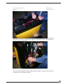
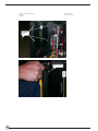
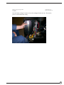
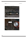
Ept-****-30 change out instructions for
Battery ....................................................................72 - 77
Charger ..................................................................78 - 85
Charger Conversion to Soneil Brand...................86 - 97
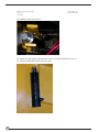
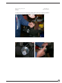
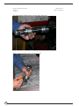
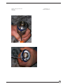
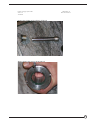
Cylinder ................................................................98 - 113
Belly Switch Troubleshooting ...........................114 - 130
Program Values ..........................................................131
Troubleshooting Guide ......................................132 - 136
Warranty .....................................................................137
EPT-30-SERIES PARTS ...................................138 - 143
2
MANUAL
1207&
1207A
MultiMode™
MOTOR CONTROLLERS
© 1999 CURTIS INSTRUMENTS, INC.
DESIGN OF CURTIS PMC 1200 SERIES
CONTROLLERS PROTECTED BY U.S.
PATENT NO. 4626750.
CURTIS PMC
235 East Airway Boulevard
Livermore, California 94568 USA
Tel: 925-961-1088
Fax: 925-961-1099
www.curtisinst.com
1207 / 1207A Manual
p/n 16081, Rev. D: August 1999
3
1207 / 1207A Manual
p/n 16081, Rev. D: August 1999
© 1999 CURTIS INSTRUMENTS, INC.
This electronic version of the 1207/1207A manual is offered as a convenience to our
customers. You may download any or all of it.
If you would like a hard copy of the published manual, please order it by part number from
the Curtis office nearest you.
The electronic version of the manual is identical to the printed version published in August
1999 and revised March 2000. The revisions are in Figures 4, 4A, and 9A (on pages 8, 24,
and 28).
Bookmarks have been added to the electronic version to speed the process of going
directly to a particular part of the document.
CURTIS INSTRUMENTS, INC.
200 KISCO AVENUE
MOUNT KISCO, NEW YORK 10549 USA
☎ 914-666-2971 FAX 914-666-2188
■ CURTIS PMC
235 EAST AIRWAY BOULEVARD
LIVERMORE, CALIFORNIA 94550 USA
☎ 925-961-1088 FAX 925-961-1099
■ ADDITIONAL OFFICES located in
Bulgaria, China, England, France, Germany,
India, Italy, Japan, Netherlands, Puerto Rico,
Russia, Sweden, and Switzerland
4
CONTENTS
CONTENTS
1.
OVERVIEW .............................................................................. 1
2.
INSTALLATION AND WIRING: 1207 controllers ................ 3
1207 Mounting ................................................................... 3
1207 Connections: Low Current ........................................ 4
1207 Connections: High Current ....................................... 5
1207 Adjustment Panel ....................................................... 5
1207 Wiring: Standard Configuration (Series Motor) ......... 6
Power wiring for series motor ...................................... 7
Control wiring for series motor .................................... 7
1207 Wiring: Compound Motor Configuration ................. 8
Power wiring for compound motor .............................. 9
Control wiring for compound motor ........................... 9
1207 Wiring: Throttle ...................................................... 10
5kΩ–0 throttle (“Type 1”) ......................................... 10
0–5V, 0–10V, 3-wire potentiometer, and
electronic throttles (“Type 2”) ................................ 11
0–5kΩ throttle (“Type 3”) ......................................... 15
1207 Wiring: Emergency Reverse Check .......................... 15
1207 Switches and Other Hardware ................................. 16
Keyswitch ................................................................... 16
Main contactor .......................................................... 16
Forward/reverse contactors ......................................... 16
F/R and emergency reverse switches ........................... 16
Circuitry protection devices ....................................... 16
1207 Installation Checkout ............................................... 17
2A. INSTALLATION AND WIRING: 1207A controllers ............ 19
1207A Mounting .............................................................. 19
1207A Connections: Low Current .................................... 20
1207A Connections: High Current ................................... 21
1207A Wiring: Standard Configuration (Series Motor) .... 22
Power wiring for series motor .................................... 23
Control wiring for series motor .................................. 23
Curtis PMC 1207/1207A Manual
12345678901
12345678901
12345678901
12345678901
12345678901
12345678901
12345678901
12345678901
12345678901
12345678901
12345678901
12345678901
12345678901
12345678901
12345678901
12345678901
12345678901
12345678901
12345678901
12345678901
12345678901
12345678901
12345678901
12345678901
12345678901
12345678901
12345678901
12345678901
12345678901
12345678901
12345678901
12345678901
12345678901
12345678901
12345678901
12345678901
12345678901
12345678901
12345678901
12345678901
12345678901
12345678901
12345678901
12345678901
12345678901
12345678901
12345678901
12345678901
12345678901
12345678901
12345678901
12345678901
12345678901
12345678901
12345678901
12345678901
12345678901
12345678901
12345678901
12345678901
12345678901
12345678901
12345678901
12345678901
12345678901
12345678901
12345678901
12345678901
12345678901
12345678901
12345678901
12345678901
12345678901
12345678901
12345678901
12345678901
12345678901
12345678901
12345678901
12345678901
12345678901
12345678901
12345678901
12345678901
12345678901
12345678901
12345678901
12345678901
12345678901
12345678901
12345678901
12345678901
12345678901
12345678901
12345678901
12345678901
12345678901
12345678901
12345678901
12345678901
12345678901
12345678901
12345678901
12345678901
12345678901
12345678901
12345678901
12345678901
12345678901
12345678901
12345678901
12345678901
12345678901
12345678901
12345678901
12345678901
12345678901
12345678901
12345678901
12345678901
12345678901
12345678901
12345678901
12345678901
12345678901
12345678901
12345678901
12345678901
iii
5
FIGURES
FIGURES
FIG.
1: Curtis PMC 1207 and 1207A motor controllers
and handheld programmer ...........................................1
FIG.
2: Mounting dimensions,
Curtis PMC 1207 controller ........................................ 3
FIG.
3: Standard wiring diagram (series motors),
Curtis PMC 1207 controller ........................................ 6
FIG.
4: Compound motor wiring diagram,
Curtis PMC 1207 controller ........................................ 8
FIG.
5: Wiring for 5kΩ–0 throttle (1207 controller) ..............10
FIG.
6: Wiring for 20kΩ potentiometer
used as a wigwag-style throttle (1207 controller) ........10
FIG.
7: Wiring for 0–5V throttle (1207 controller) ................11
FIG.
8: Wiring for 0–10V throttle (1207 controller) .............. 12
FIG.
9: Wiring for 3-wire pot throttle (1207 controller) .........13
FIG.
10: Wiring for Curtis ET-XXX electronic throttle
(1207 controller) ........................................................ 14
FIG.
11: Wiring for 0–5kΩ throttle (1207 controller) ..............15
FIG.
2A: Mounting dimensions,
Curtis PMC 1207A controller ....................................19
FIG.
3A: Standard wiring diagram (series motors),
Curtis PMC 1207A controller ....................................21
FIG.
4A: Compound motor wiring diagram,
Curtis PMC 1207A controller ....................................24
FIG.
5A: Wiring for 5kΩ–0 throttle (1207A controller) ...........26
Curtis PMC 1207/1207A Manual
6
v
FIGURES/TABLES
FIG.
6A: Wiring for 20kΩ potentiometer
used as a wigwag-style throttle (1207A controller) ......26
FIG.
7A: Wiring for 0–5V throttle (1207A controller) .............27
FIG.
8A: Wiring for 3-wire pot throttle (1207A controller) ......28
FIG.
9A: Wiring for Curtis ET-XXX electronic throttle
(1207A controller) ......................................................28
FIG.
10A: Wiring for 0–5kΩ throttle (1207A controller) ...........29
FIG.
11A: Alternative wiring for emergency reverse check
(1207A controller) ......................................................29
TABLES
TABLE
1: LED codes ..................................................................37
TABLE
2: Troubleshooting chart ................................................39
Curtis PMC 1207/1207A Manual
vi
7
1 — OVERVIEW
1
OVERVIEW
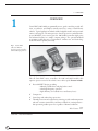
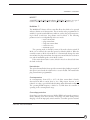
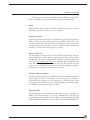
Curtis PMC 1207/1207A programmable motor speed controllers provide efficient, cost-effective, and simple-to-install control for a variety of small electric
vehicles. Typical applications include walkie fork/pallet trucks, mini personnel
carriers, and sweepers. The microprocessor-based logic section combined with a
proven MOSFET power section gives the 1207/1207A controllers high power
and advanced features in a simple, compact package. The optional handheld
programmer enables the user to set parameters, conduct tests, and obtain diagnostic information quickly and easily.
Fig. 1 Curtis PMC
1207 and 1207A
electronic motor controllers
and handheld programmer.
Like all Curtis PMC motor controllers, the 1207 and 1207A models offer
superior operator control of the vehicle’s motor drive speed. Features include:
✓
Power MOSFET design, providing
• infinitely variable drive and plug brake control
• silent high-frequency operation
• high efficiency (for reduced motor and battery losses)
✓
Compact size
✓
Overvoltage and undervoltage protection
✓
Thermal protection and compensation circuitry provides undertemperature
cutback, constant current limit, and linear rollback in overtemperature—
thus preventing sudden power loss regardless of thermal conditions
More Features
Curtis PMC 1207/1207A Manual
8
☞
1
1 — OVERVIEW
✓
Intelligent handheld programmer (optional) provides a full set of parameter
and function settings
✓
Diagnostic and test information for the controller—and other system components—readily available both on-board and through the programmer
✓
On-board potentiometers allow direct manual adjustment of acceleration
rate, creep speed, maximum speed, plug current, and main current limit
(1207 single-mode models only)
✓
Circuitry and software detects faults in the throttle circuit, MOSFET drive
circuit, MOSFET transistors, contactor drivers, and contactors—ensuring
that the controller meets EEC fault detect requirements
✓
Input sequencing options include neutral start and static return to off (SRO)
✓
Microprocessor-controlled contactor sequencing provides true arcless
contactor switching
✓
Smooth, controlled plug braking—with either variable (throttle-dependent)
or fixed plug current limit
✓
Neutral braking option provides automatic plug braking in neutral
✓
MultiMode™ input selects between two different operating modes, thus
allowing optimization of vehicle characteristics for different driving conditions
✓
Emergency reverse (belly button switch) with a single input
✓
Ramp-start feature provides full power for starting on ramps
✓
Simple contactor and switch wiring, with coil drivers monitored for faults—
thus ensuring fail-safe operation
✓
Flexible throttle circuitry accommodates a variety of throttle types
✓
Programmable “ramp shape” (static throttle map) provides flexibility in
selecting throttle response feel
✓
Connections made by solid copper power busses with a polarized Molex
connector for control signals
✓
Solid, well-protected construction—with an aluminum mounting plate and
injection-molded cover.
Familiarity with your Curtis PMC controller will help you install and operate it
properly. We encourage you to read this manual carefully. If you have questions,
please contact the Curtis office nearest you.
Curtis PMC 1207/1207A Manual
2
9
2 — INSTALLATION & WIRING: 1207 Controller
2
INSTALLATION AND WIRING: 1207
MOUNTING
The 1207 controller can be oriented in any position, but the location should be
carefully chosen to keep the controller as clean and dry as possible. If a clean
mounting location cannot be found, a cover must be used to shield the
controller from water and contaminants.
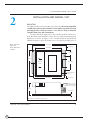
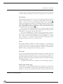
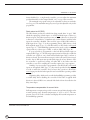
To ensure full rated output power, the controller should be fastened to a
clean, flat metal surface with three screws. The case outline and mounting hole
dimensions are shown in Figure 2. The controller should be mounted with
sufficient clearance to allow the sliding cover to be opened, providing access to
Fig. 2 Mounting
dimensions,
Curtis PMC 1207
controller.
165 (6.50)
127 (5.00)
22 (0.85)
28 (1.10)
122
(4.80)
CL
66 (2.60)
SLIDING
COVER
6.6 (0.26) dia.,
3 plcs
152 (6.00)
6.5 (0.25)
21 × 16 × 1.5
(0.83 × 0.63 × 0.06);
8.4 (0.33) dia. hole thru
60
(2.35)
4.8 (0.19)
Dimensions in millimeters and (inches)
Curtis PMC 1207/1207A Manual
10
3
2 — INSTALLATION & WIRING: 1207 Controller
the user-adjustable potentiometers. Access is also needed to plug the programmer
into the connector beneath the sliding cover, and to view the Status LED.
Although not usually necessary, a thermal joint compound can be used to
improve heat conduction from the case to the mounting surface.
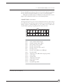
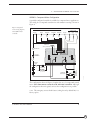
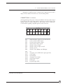
CONNECTIONS: Low Current
An integrated 16-pin low power connector molded into the front of the controller provides the low power logic control connections (see pin list below). The
mating connector is Molex Mini-Fit Jr., part number (5557) 39-01-2165.
Contact Molex regarding compatible pins for various wire sizes.
16
15
14
13
12
11
10
9
8
7
6
5
4
3
2
1
Pin 1
Pin 2
Pin 3
Pin 4
Pin 5
Pin 6
Pin 7
Pin 8
Pin 9
Pin 10
Pin 11
Pin 12
Pin 13
Pin 14
Pin 15
Pin 16
Curtis PMC 1207/1207A Manual
shunt field driver output; n/c for series motors
reverse contactor driver output
forward contactor driver output
main contactor driver output
throttle: 3-wire pot high
throttle: 3-wire pot wiper or 0–5V
throttle: pot low
throttle: 2-wire 5kΩ–0 or 0–5kΩ input
throttle: 0–10V
emergency reverse (BB) check output [optional]
reverse input
forward input
emergency reverse input
mode selection input
brake input
keyswitch input (KSI)
4
11
2 — INSTALLATION & WIRING: 1207 Controller
CONNECTIONS: High Current
Four tin-plated copper bus bars are provided for the high current connections to
the battery and motor:
MBB+
A2
A2
MB-
output to motor armature
negative connection to battery
positive connection to battery/field
plug diode to motor armature
B+
Cables are fastened to the bus bars by M8 (5⁄16") bolts.
When tightening the bolts, two opposing wrenches
should be used to prevent bending the bus bars and
putting undue strain on the internal connections.
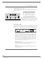
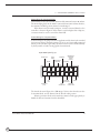
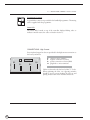
ADJUSTMENT PANEL
The adjustment panel is located on top of the 1207 controller, under a sliding
protective cover. The panel provides access to a set of adjustable potentiometers,
and also contains the Status LED and a connector for the handheld programmer.
1
2
1
2
1
2
1
2
1
2
0
3
0
3
0
3
0
3
0
3
OFF
4
OFF
4
OFF
4
OFF
4
OFF
4
MAIN
PLUG
ACCEL.
CREEP
CURRENT L I M I T
L O W
S TAT U S
SPEED L I M I T
Manually Adjustable Potentiometers
Five screwdriver-adjustable potentiometers (“trimpots”) allow manual
adjustment of the main and plug current limits, acceleration rate,
maximum creep speed, and maximum speed (labeled “LOW”), as described in Section 3. The trimpots can be enabled or disabled at the
factory; if they are enabled, MultiMode™ operation is not available.
NOTE: To adjust any of these parameters electronically with the programmer, its potentiometer must be set to “OFF.”
Programmer Connector
An RJ11 modular connector is provided for the handheld programmer.
The mating cable is supplied with the programmer.
Status LED
The LED displays flashing codes to indicate controller status; the codes
are listed in Section 5.
Curtis PMC 1207/1207A Manual
12
5
2 — INSTALLATION & WIRING: 1207 Controller
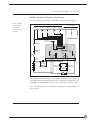
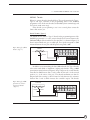
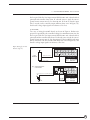
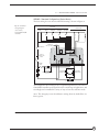
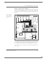
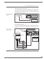
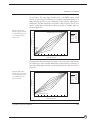
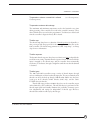
WIRING: Standard Configuration (Series Motor)
The basic wiring for series motors with field reversing is shown in Figure 3.
Fig. 3 Standard
wiring diagram
(series motor),
Curtis PMC 1207
controller.
SWITCHES
CONTACTORS
MULTI
MODE
BRAKE
EMERGENCY
REVERSE
FORWARD
REVERSE
REVERSE
FORWARD
MAIN
THROTTLE
5kΩ–0 (TYPICAL)
KEYSWITCH
POLARITY
PROTECTION
DIODE
CONTROL
FUSE
M-
A2
B-
B+
POWER
FUSE
B+
MAIN
CONTACTOR
PRECHARGE RESISTOR
(250 Ω, 5 W)
S2
FORWARD
CONTACTOR
S1
REVERSE
CONTACTOR
BA1
A
A2
The configuration shown in Figure 3 is a typical arrangement for a series motor.
Curtis PMC controllers are designed for use in a wide range of applications, and
accordingly can be installed in a variety of ways to best meet customer needs.
NOTE:
The emergency reverse check feature (wiring shown by dashed line) is a
factory option.
Curtis PMC 1207/1207A Manual
6
13
2 — INSTALLATION & WIRING: 1207 Controller
Power Wiring for Series Motor
In every wiring configuration, it is imperative that the field be wired between the
controller’s B+ and A2 terminals and that the armature be wired between the Mand A2 terminals. The internal plug diode used in the 1207 is connected between
M- and A2 . Therefore, the armature and field positions cannot be interchanged.
Reversing contactors can be used to switch either the armature or the field.
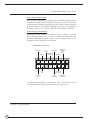
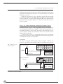
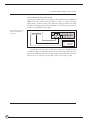
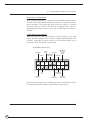
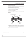
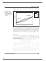
Control Wiring for Series Motor
Wiring for the input switches and contactors is shown in Figure 3 (see detail
below). The main contactor, if one is used, is normally connected directly to the
controller. Optionally, the main contactor can be switched directly by the
keyswitch or brake, leaving Pin 4 unconnected.
16-pin detail (see Fig. 3):
MULTI
MODE
KEYSWITCH
EMERGENCY
REVERSE
BRAKE
EMERGENCY
REVERSE
CHECK
OUTPUT
FORWARD
REVERSE
16
15
14
13
12
11
10
9
8
7
6
5
4
3
2
1
POT
LOW
2-WIRE POT
(5 kΩ)
FORWARD
CONTACTOR
MAIN
CONTACTOR
REVERSE
CONTACTOR
The throttle shown in Figure 3 is a 5kΩ–0 type. Various other throttles can also
be accommodated, and are discussed in the throttle wiring section.
Curtis PMC 1207/1207A Manual
14
7
2 — INSTALLATION & WIRING: 1207 Controller
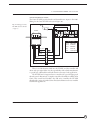
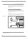
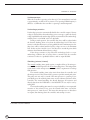
WIRING: Compound Motor Configuration
A specially configured controller is available for compound motor applications.
The wiring for a compound wound motor with armature reversing is shown in
Figure 4.
Fig. 4 Compound
motor wiring diagram,
Curtis PMC 1207
controller.
SWITCHES
CONTACTORS
MULTI
MODE
BRAKE
EMERGENCY
REVERSE
FORWARD
REVERSE
SHUNT
REV
FWD
MAIN
THROTTLE
5kΩ–0 (TYPICAL)
KEYSWITCH
POLARITY
PROTECTION
DIODE
CONTROL
FUSE
M-
A2
B-
B+
POWER
FUSE
S2
B+
MAIN
CONTACTOR
PRECHARGE RESISTOR
(250 Ω, 5 W)
A1
A2
A
3/28/00
B-
FORWARD
CONTACTOR
REVERSE
CONTACTOR
S1
The configuration shown in Figure 4 requires the use of a compound wound
motor. Pure shunt motors cannot be used with 1207 controllers. Although
the configuration shown is typical, various other configurations are possible.
NOTE: The emergency reverse check feature (wiring shown by dashed line) is a
factory option.
Curtis PMC 1207/1207A Manual
8
15
2 — INSTALLATION & WIRING: 1207 Controller
Power Wiring for Compound Motor
The field must be wired between B+ and A2 and the armature between M- and A2 .
The internal plug diode in the 1207 is connected between M- and A2 ; therefore,
the armature and field positions cannot be interchanged.
If the shunt is rated for under 2 amperes, it can be connected directly to the
controller as shown in Figure 4. If the shunt is rated for higher than 2 amperes,
a contactor must be used to control the shunt field.
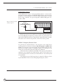
Control Wiring for Compound Motor
Control wiring for the compound motor application is like that for the standard
(series motor) wiring. The main contactor, if one is used, is normally connected
directly to the controller. Optionally, the main contactor can be switched directly
by the keyswitch or brake, leaving pig Pin 4 unconnected.
16-pin detail (see Fig. 4):
MULTI
MODE
KEYSWITCH
EMERGENCY
REVERSE
BRAKE
EMERGENCY
REVERSE
CHECK
OUTPUT
FORWARD
REVERSE
16
15
14
13
12
11
10
9
8
7
6
5
4
3
2
1
POT
LOW
2-WIRE POT
(5 kΩ)
FORWARD
CONTACTOR
MAIN
CONTACTOR
SHUNT
REVERSE
CONTACTOR
The throttle shown in Figure 4 is a 5kΩ–0 type. Various other throttles can also
be accommodated, and are discussed in the throttle wiring section.
Polarity protection diodes and control fuses must be sized appropriately to
handle the increased current from the shunt field.
Curtis PMC 1207/1207A Manual
16
9
2 — INSTALLATION & WIRING: 1207 Controller
WIRING: Throttle
Wiring for various throttles is described below. They are characterized as Type 1,
Type 2, and Type 3 throttles in the programming menu of the handheld
programmer. NOTE: In the text, throttles are identified by their nominal range and
not by their actual active range.
If the throttle you are planning to use is not covered, please contact the
Curtis office nearest you.
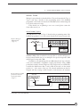
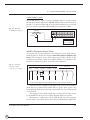
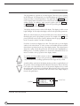
5kΩ–0 Throttle (“Type 1”)
The 5kΩ–0 throttle (called a “Type 1” throttle in the programming menu of the
handheld programmer) is a 2-wire resistive throttle that connects between the
5kΩ–0/0–5kΩ pin (Pin 8) and the Pot Low pin (Pin 7), as shown in Figure 5. It
doesn’t matter which wire goes on which pin. Zero speed corresponds to 5kΩ
measured between the two pins and full speed corresponds to 0Ω.
Fig. 5 Wiring for 5kΩ–0
5kΩ POT
throttle (“Type 1”).
16
15
14
13
12
11
10
9
8
7
6
5
4
3
2
1
FASTER
PIN KEY (1207)
Pin 8
Pin 7
5kΩ–0
Pot Low
In addition to accommodating the basic 5kΩ–0 throttle, the Type 1 throttle
is the easiest with which to implement a wigwag-style throttle. Using a 20kΩ
potentiometer wired as shown in Figure 6, the pot wiper can be set such that the
controller has 5kΩ between Pins 7 and 8 when the throttle is in the neutral
position (i.e., at the center of the pot). The throttle mechanism can then be
designed such that rotating it either forward or back decreases the resistance
between Pins 7 and 8, which increases the controller output. The throttle
Fig. 6 Wiring for 20kΩ
potentiometer used as a
wigwag-style throttle
(“Type 1”).
20 kΩ POT
FASTER
FASTER
16
15
14
13
12
11
10
9
8
7
6
5
4
3
2
1
PIN KEY (1207)
Pin 8
Pin 7
Curtis PMC 1207/1207A Manual
5kΩ–0
Pot Low
10
17
2 — INSTALLATION & WIRING: 1207 Controller
mechanism must provide signals to the controller’s forward and reverse inputs
independent of the throttle pot resistance. The controller will not sense direction
from the pot resistance.
Broken wire protection for Type 1 throttles is provided by the controller
sensing the current flow from the 5kΩ–0 input through the pot and into the Pot
Low pin. If the Pot Low input current falls below 0.1 mA, a throttle fault is
generated and the controller is disabled. NOTE: The Pot Low pin (Pin 7) must not
be tied to ground.
0–5V, 0–10V, 3-Wire Potentiometer, and Electronic Throttles (“Type 2”)
With these throttles (“Type 2” in the programming menu), the controller looks
for a voltage signal at either the pot wiper/0–5V input of the controller (Pin 6) or
the 0–10V input (Pin 9). Zero speed corresponds to 0V and full speed corresponds to either 5V or 10V, measured relative to B-. Pot Low is the current return
path for all Type 2 throttles.
A voltage source, 3-wire pot, or electronic throttle can be used with this
throttle type. The wiring for each is slightly different and each has varying levels
of throttle fault detection associated with it.
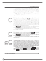
0–5V Throttle
Two ways of wiring the 0–5V throttle are shown in Figure 7. Broken wire
protection is provided by the controller looking for a minimum current into the
Fig. 7 Wiring for 0–5V
throttle (“Type 2”).
(a) 0–5V throttle sensor
+
0–5V
SENSOR
16
15
14
13
12
11
10
9
8
7
6
5
4
3
2
1
SENSOR OUTPUT
PIN KEY (1207)
SENSOR GROUND
(b) Ground-referenced
0–5V throttle
Pot Low
0–5V Input
Pin 7
Pin 6
16
15
14
13
12
11
10
9
8
7
6
5
4
3
2
1
(Shunt impedance 150 kΩ to ground)
+
-
Curtis PMC 1207/1207A Manual
18
PIN KEY (1207)
4.7 kΩ
B-
Pin 7
Pin 6
Pin 5
Pot Low
0–5V Input
Pot High
11
2 — INSTALLATION & WIRING: 1207 Controller
Pot Low pin. If the Pot Low input current falls below 0.1 mA, a throttle fault is
generated and controller shuts down. If a throttle sensor is used, the sensor’s
ground return current must be less than 10 mA. If the 0–5V throttle input
(Pin 7) exceeds 8 volts, controller output will shut down. NOTE: In Figure 7(b),
the throttle’s voltage input signal is in reference to Pot Low.
0–10V Throttle
Two ways of wiring the 0–10V throttle are shown in Figure 8. Broken wire
protection is provided by the controller looking for a minimum current into the
Pot Low pin. If the Pot Low input current falls below 0.1 mA, a throttle fault is
generated and the controller shuts down. If a throttle sensor is used, the sensor’s
ground return current must be less than 10 mA. If the 0–10V throttle input
(Pin 9) exceeds 16 volts, the controller will shut down. NOTE: In Figure 8(b), the
throttle’s voltage input signal is in reference to Pot Low.
Fig. 8 Wiring for 0–10V
throttle (“Type 2”).
(a) 0–10V throttle sensor
+
0–10V
SENSOR
16
15
14
13
12
11
10
9
8
7
6
5
4
3
2
1
SENSOR OUTPUT
PIN KEY (1207)
0–10V Input
Pot Low
Pin 9
Pin 7
SENSOR GROUND
(b) Ground-referenced
0–10V throttle
16
15
14
13
12
11
10
9
8
7
6
5
4
3
2
1
(Shunt impedance 150 kΩ to ground)
+
-
Curtis PMC 1207/1207A Manual
PIN KEY (1207)
4.7 kΩ
B-
Pin 9
Pin 7
Pin 5
0–10V Input
Pot Low
Pot High
12
19
2 — INSTALLATION & WIRING: 1207 Controller
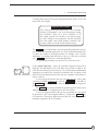
3-Wire Potentiometer (500Ω–10kΩ) Throttle
A 3-wire potentiometer with a total resistance value anywhere between 500Ω and
10kΩ can be used, wired as shown in Figure 9. The pot is used in its voltage
divider mode—with the voltage source and return being provided by the 1207
controller. Pot High provides a current-limited 5V source to the potentiometer,
and Pot Low provides the return path.
Fig. 9 Wiring for 3-wire
potentiometer throttle
(“Type 2”).
3-WIRE POT
ON
OFF
16
15
14
13
12
11
10
9
8
7
6
5
4
3
2
1
PIN KEY (1207)
Pin 7
Pin 6
Pin 5
Pot Low
0–5V Input
Pot High
As with the 2-wire throttles, broken wire protection is provided by the
controller looking for a minimum current into the Pot Low pin. If the Pot Low
input current falls below 0.1 mA, a throttle fault is generated and the controller
shuts down. NOTE: The Pot Low pin (Pin 7) must not be tied to ground.
Curtis PMC 1207/1207A Manual
20
13
2 — INSTALLATION & WIRING: 1207 Controller
Curtis ET-XXX Electronic Throttle
The Curtis ET-XXX provides throttle and forward/reverse inputs to the 1207.
Wiring for the Curtis ET-XXX is shown in Figure 10.
Fig. 10 Wiring for Curtis
B+
ET-XXX electronic throttle
(“Type 2”).
KEYSWITCH
ET-XXX
16
15
14
13
12
11
10
9
8
7
6
5
4
3
2
1
PIN KEY (1207)
WHT/
GRN
WHT/BRN
GREEN
B-
Pin 16
Pin 12
Pin 11
KSI Input
Forward
Reverse
Pin 7
Pin 6
Pot Low
0–5V Input
ORANGE
BLACK
BLACK/WHITE
WHITE
There is no fault detection built into the ET-XXX, and the controller will
detect only open wiper faults. It is the responsibility of the vehicle manufacturer
to provide any additional throttle fault detection necessary for the application.
The ET-XXX can be integrated into a control head to provide wigwag-style
throttle control. Alternatively, a complete control head assembly is available from
Curtis. This control head assembly—the CH series—combines the ET-XXX
throttle with a variety of standard control head switch functions for use in walkie
and lift truck applications.
Curtis PMC 1207/1207A Manual
14
21
2 — INSTALLATION & WIRING: 1207 Controller
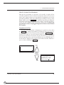
0–5kΩ Throttle (“Type 3”)
The 0–5kΩ throttle (“Type 3” in the programming menu) is a 2-wire resistive
throttle that connects between the 5kΩ–0/0–5kΩ pin (Pin 8) and the Pot Low
pin (Pin 7), as shown in Figure 11. It doesn’t matter which wire goes on which
pin. For Type 3 throttles, zero speed corresponds to 0Ω and full speed corresponds to 5kΩ.
Fig. 11 Wiring for 0–5Ω
5kΩ POT
throttle (“Type 3”).
16
15
14
13
12
11
10
9
8
7
6
5
4
3
2
1
FASTER
PIN KEY (1207)
Pin 8
Pin 7
5kΩ–0
Pot Low
Broken wire protection is provided by the controller sensing the current flow
from the 0–5kΩ input through the pot and into the Pot Low pin. If the Pot Low
input current falls below 0.1 mA, a throttle fault is generated and the controller
shuts down. NOTE: The Pot Low pin (Pin 7) must not be tied to ground.
WIRING: Emergency Reverse Check
An optional wire connected directly to the emergency reverse (belly button)
switch provides for broken wire detection when that option is enabled at the
factory. The emergency reverse check output wire periodically pulses the emergency reverse circuit to check for continuity. If there is no continuity in the
circuit, the controller shuts down and a fault code is indicated.
This feature must be enabled at Curtis PMC. If the option is selected and the
check wire is not connected, the vehicle will not operate. If the option is not
selected and the check wire is connected, no harm will occur—but continuity will
not be checked.
The emergency reverse check output wire is connected to Pin 10, as shown
by the dashed lines in the two basic wiring diagrams (Figures 3 and 4).
Curtis PMC 1207/1207A Manual
22
15
2 — INSTALLATION & WIRING: 1207 Controller
SWITCHES AND OTHER HARDWARE
Keyswitch
The vehicle should have a master on/off switch to turn the system off when not
in use. The keyswitch provides logic power for the 1207 controller, coil current
for the contactors, and shunt current (in compound motor applications). The
keyswitch must be capable of carrying these currents.
Main Contactor
A main contactor allows the 1207 controller to be disconnected from the battery.
In 24V applications a main contactor is optional, but in 36V applications a
main contactor is required. A heavy-duty single-pole, single-throw (SPST)
contactor with silver-alloy contacts is recommended, such as an Albright SW80
or SW180 (available from Curtis).
After initial closing of the contacts, inrush currents flow as the controller’s
internal filter capacitors are charged. A 250Ω, 5W resistor (such as Curtis PMC
p/n MP-2) can be used across the contactor to precharge the capacitors and
reduce the inrush current through the contacts.
Forward/Reverse Contactors
For forward/reverse, a paired single-pole, double-throw (2×SPDT) contactor is
recommended, such as an Albright DC88 or DC182 (available from Curtis).
With 4-terminal split field motors, two single-pole, single-throw (SPST) contactors are typically used. The coil voltage should match the vehicle voltage. The
maximum allowed coil current is 1 ampere.
Forward/Reverse, Emergency Reverse, and Mode Switches
The direction input switches can be any type of single-pole, single-throw (SPST)
switch capable of switching the battery voltage at 10 mA.
Circuitry Protection Devices
For reverse polarity protection, a diode should be added to the control circuit. It
must be sized appropriately for the maximum contactor coil currents (and shunt
current, in compound motor applications). To protect the control wiring from
accidental shorts, a low current fuse (appropriate for the maximum current draw)
should be connected in series with the battery feed. These devices are both shown
in the wiring diagrams.
Curtis PMC 1207/1207A Manual
16
23
2 — INSTALLATION & WIRING: 1207 Controller
1207 INSTALLATION CHECKOUT
Before operating the vehicle, carefully complete the following checkout procedure. If you find a problem during the checkout, refer to the diagnostics and
troubleshooting section (Section 5) for further information.
The installation checkout can be conducted with or without the handheld
programmer. The checkout procedure is easier with a programmer. Otherwise,
observe the Status LED for codes.
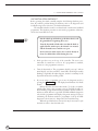
☞
Put the vehicle up on blocks to get the drive wheel(s) off
the ground before beginning these tests.
CAUTION
Turn the keyswitch off and make sure that the brake is
applied (brake switch open), the throttle is in neutral,
and the forward/reverse switches are open.
Do not stand, or allow anyone else to stand, directly in
front of or behind the vehicle during the tests.
Curtis PMC 1207/1207A Manual
24
1.
Slide open the cover on the top of the controller. The cover is not
removable; be careful not to force it. If a programmer is available,
connect it to the programmer connector.
2.
Turn the keyswitch on. The programmer should “power up” with an
initial display, and the controller’s Status LED should begin steadily
blinking a single flash. If neither happens, check for continuity in the
keyswitch circuit and controller ground.
3.
If you are using a programmer, put it into the diagnostic mode by
pressing the DIAGNOSTICS key. The display should indicate “No Faults
Found.”
Release the brake (close the brake switch). To do this on a walkie,
pull the tiller down to the operating position. The LED should continue blinking a single flash and the programmer should continue to
indicate no faults. If there is a problem, the LED will flash a diagnostic
code and the programmer will display a diagnostic message. If you are
conducting the checkout without a programmer, look up the LED
diagnostic code in Section 5: Diagnostics and Troubleshooting.
When the problem has been corrected, it may be necessary to cycle
the brake in order to clear the fault code.
17
2 — INSTALLATION & WIRING: 1207 Controller
4.
With the brake released, select a direction and operate the throttle. The
motor should begin to turn in the selected direction. If it does not,
verify the wiring to the forward/reverse switches, forward/reverse contactors, and motor. The motor should run proportionally faster with
increasing throttle. If not, refer to Section 5.
5.
If you are using a programmer, put it into the test mode by pressing
the TEST key. Scroll down to observe the status of the forward, reverse,
brake, emergency reverse, and mode switches. Cycle each switch in
turn, observing the programmer. Each input should show the correct
state on the programmer.
6.
Specific material handling directives, such as prEN1175, require testing
of the controller’s fault detection circuitry. This can be done as follows:
a) Disconnect the battery and make sure the keyswitch is off.
b) Using an inline fuse holder fitted with a 10-amp fuse and
alligator clips, connect the controller’s M- and B- terminals.
c) Turn the keyswitch on, release the brake, and apply the throttle.
The motor should not operate, and the direction contactors
should not pull in.
d) Leave the keyswitch on and remove the inline fuse wire. The
vehicle status should continue to remain off.
e) Cycle the keyswitch off and on, release the brake, and apply the
throttle. The vehicle should now operate normally.
7.
Take the vehicle off the blocks and drive it in a clear area. It should have
smooth acceleration and good top speed.
8.
Test the plug braking of the vehicle. Verify that the plug braking option
is as desired (variable or fixed).
9.
Verify that all options, such as high pedal disable (HPD), static return
to off (SRO), and anti-tiedown, are as desired.
10.
Check to see whether the emergency reverse (belly button) feature is
working correctly. If you have the optional emergency reverse check
wiring, verify that the circuit is operational by momentarily disconnecting one of the emergency reverse wires. The vehicle should be disabled
and a fault indicated.
11.
When you have completed the checkout procedure, be sure to close the
protective sliding cover.
Curtis PMC 1207/1207A Manual
18
25
2A — INSTALLATION & WIRING: 1207A Controller
2A
INSTALLATION AND WIRING: 1207A
MOUNTING
The 1207A controller can be oriented in any position, but the location should
be carefully chosen to keep the controller as clean and dry as possible. If a
clean mounting location cannot be found, a cover must be used to shield the
controller from water and contaminants.
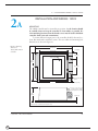
To ensure full rated output power, the controller should be fastened to a
clean, flat metal surface with three screws. The case outline and mounting hole
dimensions are shown in Figure 2A.
Fig. 2 A Mounting
165 (6.50)
dimensions,
Curtis PMC 1207A
controller.
127 (5.00)
22 (0.85)
28 (1.1)
Status LED
122
(4.80)
66 (2.6)
CL
6.7 (0.265) dia.,
3 plcs
152 (6.00)
6.3 (0.25)
21 × 16 × 1.5
(0.83 × 0.63 × 0.06);
8.4 (0.33) dia. hole thru
66
(2.60)
4.8 (0.19)
Dimensions in millimeters and (inches)
Curtis PMC 1207/1207A Manual
26
19
2A — INSTALLATION & WIRING: 1207A Controller
Although not usually necessary, a thermal joint compound can be used to
improve heat conduction from the case to the mounting surface.
CONNECTIONS: Low Current
An integrated 16-pin low power connector molded into the front of the controller provides the low power logic control connections (see pin list below). The
mating connector is Molex Mini-Fit Jr., part number (5557) 39-01-2165.
Contact Molex regarding compatible pins for various wire sizes.
16
15
14
13
12
11
10
9
8
7
6
5
4
3
2
1
Pin 1
Pin 2
Pin 3
Pin 4
Pin 5
Pin 6
Pin 7
Pin 8
Pin 9
Pin 10
Pin 11
Pin 12
Pin 13
Pin 14
Pin 15
Pin 16
Curtis PMC 1207/1207A Manual
shunt field driver output; n/c for series motors
reverse contactor driver output
forward contactor driver output
main contactor driver output
throttle: 3-wire pot high
throttle: 3-wire pot wiper or 0–5V
throttle: pot low
throttle: 2-wire 5kΩ–0 or 0–5kΩ input
n/c
emergency reverse (BB) check output [optional]
reverse input
forward input
emergency reverse input
mode selection input
brake input
keyswitch input (KSI)
20
27
2A — INSTALLATION & WIRING: 1207A Controller
Programmer Connector
A 4-pin Molex connector is provided for the handheld programmer. The mating
cable is supplied with the programmer.
Status LED
The Status LED, located on top of the controller, displays flashing codes to
indicate controller status; the codes are listed in Section 5.
CONNECTIONS: High Current
Four tin-plated copper bus bars are provided for the high current connections to
the battery and motor:
A2
MB-
B+
MBB+
A2
output to motor armature
negative connection to battery
positive connection to battery/field
plug diode to motor armature
Cables are fastened to the bus bars by M8 (5⁄16") bolts.
When tightening the bolts, two opposing wrenches
should be used to prevent bending the bus bars and
putting undue strain on the internal connections.
Curtis PMC 1207/1207A Manual
28
21
2A — INSTALLATION & WIRING: 1207A Controller
WIRING: Standard Configuration (Series Motor)
The basic wiring for series motors with field reversing is shown in Figure 3A.
Fig. 3 A Standard
SWITCHES
wiring diagram
(series motor),
Curtis PMC 1207A
controller.
CONTACTORS
MULTI
MODE
BRAKE
EMERGENCY
REVERSE
FORWARD
REVERSE
REVERSE
FORWARD
MAIN
THROTTLE
5kΩ–0 (TYPICAL)
KEYSWITCH
POLARITY
PROTECTION
DIODE
CONTROL
FUSE
M-
A2
B-
B+
POWER
FUSE
B+
MAIN
CONTACTOR
PRECHARGE RESISTOR
(250 Ω, 5 W)
S2
FORWARD
CONTACTOR
S1
REVERSE
CONTACTOR
BA1
A
A2
The configuration shown in Figure 3A is a typical arrangement for a series motor.
Curtis PMC controllers are designed for use in a wide range of applications, and
accordingly can be installed in a variety of ways to best meet customer needs.
NOTE:
The emergency reverse check feature (wiring shown by dashed line) is a
factory option.
Curtis PMC 1207/1207A Manual
22
29
2A — INSTALLATION & WIRING: 1207A Controller
Power Wiring for Series Motor
In every wiring configuration, it is imperative that the field be wired between the
controller’s B+ and A2 terminals and that the armature be wired between the Mand A2 terminals. The internal plug diode used in the 1207A is connected
between M- and A2 . Therefore, the armature and field positions cannot be
interchanged. Reversing contactors can be used to switch either the armature or
the field.
Control Wiring for Series Motor
Wiring for the input switches and contactors is shown in Figure 3A (see detail
below). The main contactor, if one is used, is normally connected directly to the
controller. Optionally, the main contactor can be switched directly by the
keyswitch or brake, leaving Pin 4 unconnected.
16-pin detail (see Fig. 3A):
MULTI
MODE
KEYSWITCH
EMERGENCY
REVERSE
BRAKE
EMERGENCY
REVERSE
CHECK
OUTPUT
FORWARD
REVERSE
16
15
14
13
12
11
10
9
8
7
6
5
4
3
2
1
POT
LOW
2-WIRE POT
(5 kΩ)
FORWARD
CONTACTOR
MAIN
CONTACTOR
REVERSE
CONTACTOR
The throttle shown in Figure 3A is a 5kΩ–0 type. Various other throttles can also
be accommodated, and are discussed in the throttle wiring section.
Curtis PMC 1207/1207A Manual
30
23
2A — INSTALLATION & WIRING: 1207A Controller
WIRING: Compound Motor Configuration
A specially configured controller is available for compound motor applications.
In this controller, the MOSFET output driver is used to drive the shunt field.
The wiring for a compound wound motor with armature reversing is shown in
Figure 4A.
Fig. 4 A Compound
SWITCHES
motor wiring diagram,
Curtis PMC 1207A
controller.
CONTACTORS
MULTI
MODE
BRAKE
EMERGENCY
REVERSE
FORWARD
REVERSE
SHUNT
REV
FWD
MAIN
BTHROTTLE
5kΩ–0 (TYPICAL)
KEYSWITCH
POLARITY
PROTECTION
DIODE
CONTROL
FUSE
M-
A2
B-
B+
POWER
FUSE
S2
B+
MAIN
CONTACTOR
B-
FORWARD
CONTACTOR
A1
A2
A
3/28/00
PRECHARGE RESISTOR
(250 Ω, 5 W)
REVERSE
CONTACTOR
S1
The configuration shown in Figure 4A requires the use of a compound wound
motor. Pure shunt motors cannot be used with 1207A controllers. Although
the configuration shown is typical, various other configurations are possible.
NOTE:
The emergency reverse check feature (wiring shown by dashed line) is a
factory option.
Curtis PMC 1207/1207A Manual
24
31
2A — INSTALLATION & WIRING: 1207A Controller
Power Wiring for Compound Motor
The field must be wired between B+ and A2 and the armature between M- and A2 .
The internal plug diode in the 1207A is connected between M- and A2 ; therefore,
the armature and field positions cannot be interchanged.
If the shunt is rated for under 2 amperes, it can be connected directly to the
controller as shown in Figure 4A. If the shunt is rated for higher than 2 amperes,
a contactor must be used to control the shunt field.
Control Wiring for Compound Motor
Control wiring for the compound motor application is like that for the standard
(series motor) wiring. The main contactor, if one is used, is normally connected
directly to B-.
16-pin detail (see Fig. 4A):
MULTI
MODE
KEYSWITCH
EMERGENCY
REVERSE
BRAKE
EMERGENCY
REVERSE
CHECK
OUTPUT
FORWARD
REVERSE
16
15
14
13
12
11
10
9
8
7
6
5
4
3
2
1
POT
LOW
2-WIRE POT
(5 kΩ)
FORWARD
CONTACTOR
SHUNT
REVERSE
CONTACTOR
The throttle shown in Figure 4A is a 5kΩ–0 type. Various other throttles can also
be accommodated, and are discussed in the throttle wiring section.
Polarity protection diodes and control fuses must be sized appropriately to
handle the increased current from the shunt field.
Curtis PMC 1207/1207A Manual
32
25
2A — INSTALLATION & WIRING: 1207A Controller
WIRING: Throttle
Wiring for various throttles is described below. They are characterized as Type 1,
Type 2, and Type 3 throttles in the programming menu of the handheld
programmer. NOTE: In the text, throttles are identified by their nominal range and
not by their actual active range.
If the throttle you are planning to use is not covered, please contact the
Curtis office nearest you.
5kΩ–0 Throttle (“Type 1”)
The 5kΩ–0 throttle (called a “Type 1” throttle in the programming menu of the
handheld programmer) is a 2-wire resistive throttle that connects between the
Fig. 5 A Wiring for
5kΩ–0 throttle
(“Type 1”).
5kΩ POT
16
15
14
13
12
11
10
9
8
7
6
5
4
3
2
1
FASTER
PIN KEY (1207A)
Pin 8
Pin 7
5kΩ–0
Pot Low
5kΩ–0/0–5kΩ pin (Pin 8) and the Pot Low pin (Pin 7), as shown in Figure 5A.
It doesn’t matter which wire goes on which pin. Zero speed corresponds to 5kΩ
and full speed corresponds to 0Ω.
In addition to accommodating the basic 5kΩ–0 throttle, the Type 1 throttle
is the easiest with which to implement a wigwag-style throttle. Using a 20kΩ
potentiometer wired as shown in Figure 6A, the pot wiper can be set such that the
controller has 5kΩ between Pins 7 and 8 when the throttle is in the neutral
position (i.e., at the center of the pot). The throttle mechanism can then be
designed such that rotating it either forward or back decreases the resistance
Fig. 6 A Wiring for 20kΩ
potentiometer used as a
wigwag-style throttle
(“Type 1”).
20 kΩ POT
FASTER
FASTER
16
15
14
13
12
11
10
9
8
7
6
5
4
3
2
1
PIN KEY (1207A)
Pin 8
Pin 7
Curtis PMC 1207/1207A Manual
5kΩ–0
Pot Low
26
33
2A — INSTALLATION & WIRING: 1207A Controller
between Pins 7 and 8, which increases the controller output. The throttle
mechanism must provide signals to the controller’s forward and reverse inputs
independent of the throttle pot resistance. The controller will not sense direction
from the pot resistance.
0–5V, 3-Wire Potentiometer, and Electronic Throttles (“Type 2”)
With these throttles (“Type 2” in the programming menu), the controller looks
for a voltage signal at the pot wiper/0–5V input of the controller (Pin 6). Zero
speed corresponds to 0V and full speed corresponds to 5V. Pot Low is the current
return path for all Type 2 throttles.
0–5V Throttle
Two ways of wiring the 0–5V throttle are shown in Figure 7A. If a throttle sensor
is used, the sensor’s ground return current must be less than 10 mA. If the 0–5V
throttle input (Pin 6) exceeds 8 volts, the controller will shut down.
Fig. 7 A Wiring for 0–5V
throttle (“Type 2”).
(a) 0–5V throttle sensor
+
0–5V
SENSOR
16
15
14
13
12
11
10
9
8
7
6
5
4
3
2
1
SENSOR OUTPUT
PIN KEY (1207A)
Pot Low
0–5V Input
Pin 7
Pin 6
SENSOR GROUND
(b) Ground-referenced
0–5V throttle
16
15
14
13
12
11
10
9
8
7
6
5
4
3
2
1
(Shunt impedance 150 kΩ to ground)
+
-
Curtis PMC 1207/1207A Manual
34
PIN KEY (1207A)
4.7 kΩ
B-
Pin 7
Pin 6
Pin 5
Pot Low
0–5V Input
Pot High
27
2A — INSTALLATION & WIRING: 1207A Controller
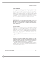
3-Wire Potentiometer (500Ω–10kΩ) Throttle
The 3-wire potentiometer is used in its voltage divider mode—with the voltage
source and return being provided by the 1207A controller. Pot High provides a
current-limited 5V source to the potentiometer, and Pot Low provides the return
path. Wiring is shown in Figure 8A.
Fig. 8 A Wiring for 3-wire
potentiometer throttle
(“Type 2”).
3-WIRE POT
ON
OFF
16
15
14
13
12
11
10
9
8
7
6
5
4
3
2
1
PIN KEY (1207A)
Pot Low
0–5V Input
Pot High
Pin 7
Pin 6
Pin 5
Curtis ET-XXX Electronic Throttle
The Curtis ET-XXX (manufactured by Hardellet) provides throttle and forward/
reverse inputs to the 1207A controller. Wiring for the Curtis ET-XXX is shown
in Figure 9A.
Fig. 9 A Wiring for
B+
Curtis ET-XXX electronic
throttle (“Type 2”).
KEYSWITCH
ET-XXX
16
15
14
13
12
11
10
9
8
7
6
5
4
3
2
1
PIN KEY (1207A)
WHT/
GRN
WHT/BRN
GREEN
Pin 16
Pin 12
Pin 11
KSI Input
Forward
Reverse
Pin 6
0–5V Input
B-
ORANGE
BLACK
B-
BLACK/WHITE
Curtis PMC 1207/1207A Manual
3/28/00
WHITE
28
35
2A — INSTALLATION & WIRING: 1207A Controller
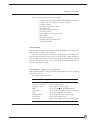
0–5kΩ Throttle (“Type 3”)
The 0–5kΩ throttle (“Type 3” in the programming menu) is a 2-wire resistive
throttle that connects between the 5kΩ–0/0–5kΩ pin (Pin 8) and the Pot Low
pin (Pin 7), as shown in Figure 10A. It doesn’t matter which wire goes on which
pin. Zero speed corresponds to 0Ω and full speed corresponds to 5kΩ.
Fig. 10 A Wiring for
0–5Ω throttle (“Type 3”).
5kΩ POT
16
15
14
13
12
11
10
9
8
7
6
5
4
3
2
1
FASTER
PIN KEY (1207A)
Pin 8
Pin 7
5kΩ–0
Pot Low
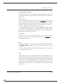
WIRING: Emergency Reverse Check
An optional wire connected directly to the emergency reverse (belly button)
switch provides for broken wire detection when that option is enabled at the
factory. The emergency reverse check output wire provides a dc bias to the
emergency reverse circuit to check for continuity. If there is no continuity in the
circuit, the controller shuts down and a fault code is indicated.
SWITCHES
CONTACTORS
BRAKE
MULTI
MODE
EMERGENCY
REVERSE
FORWARD
REVERSE
REVERSE
FORWARD
MAIN
9.1 kΩ
Fig. 11 A Alternative
wiring for 1207A
emergency reverse check.
For rest of wiring diagram, see Fig. 3A (series motors) or Fig. 4A (compound motors).
This feature must be enabled at Curtis PMC. If the option is selected and the
check wire is not connected, the vehicle will not operate. If the option is not
selected and the check wire is connected, no harm will occur—but continuity will
not be checked.
The emergency reverse check output wire is connected to Pin 10, as shown
by the dashed lines in the two basic wiring diagrams (Figures 3A and 4A).
Alternatively, a 9.1kΩ resistor can be wired directly across the emergency
reverse switch to provide the dc bias, as shown by the dashed line in Figure 10A.
Curtis PMC 1207/1207A Manual
36
29
2A — INSTALLATION & WIRING: 1207A Controller
SWITCHES AND OTHER HARDWARE
Keyswitch
The vehicle should have a master on/off switch to turn the system off when not
in use. The keyswitch provides logic power for the 1207A controller, coil current
for the contactors, and shunt current (in compound motor applications). The
keyswitch must be capable of carrying these currents.
Main Contactor
A main contactor allows the 1207A controller to be disconnected from the
battery. A heavy-duty single-pole, single-throw (SPST) contactor with silveralloy contacts is recommended, such as an Albright SW80 or SW180 (available
from Curtis).
After initial closing of the contacts, inrush currents flow as the controller’s
internal filter capacitors are charged. A 250Ω, 5W resistor (such as Curtis PMC
p/n MP-2) can be used across the contactor to precharge the capacitors and
reduce the inrush current through the contacts.
In compound motor applications, the main contactor driver is used to drive
the shunt field. The main contactor—if one is used—is normally connected
directly to B- in this configuration.
Forward/Reverse Contactors
For forward/reverse, a paired single-pole, double-throw (2×SPDT) contactor is
recommended, such as an Albright DC88 or DC182 (available from Curtis).
With 4-terminal split field motors, two single-pole, single-throw (SPST) contactors are typically used. The coil voltage should match the vehicle voltage. The
maximum allowed coil current is 1 ampere.
Forward/Reverse, Emergency Reverse, and Mode Switches
The direction input switches can be any type of single-pole, single-throw (SPST)
switch capable of switching the battery voltage at 10 mA.
Circuitry Protection Devices
For reverse polarity protection, a diode should be added to the control circuit. It
must be sized appropriately for the maximum contactor coil currents (and shunt
current, in compound motor applications). To protect the control wiring from
accidental shorts, a low current fuse (appropriate for the maximum current draw)
should be connected in series with the battery feed. These devices are both shown
in the wiring diagrams.
Curtis PMC 1207/1207A Manual
30
37
2A — INSTALLATION & WIRING: 1207A Controller
1207A INSTALLATION CHECKOUT
Before operating the vehicle, carefully complete the following checkout procedure. If you find a problem during the checkout, refer to the diagnostics and
troubleshooting section (Section 5) for further information.
The installation checkout can be conducted with or without the handheld
programmer. The checkout procedure is easier with a programmer. Otherwise,
observe the Status LED for codes.
☞
Put the vehicle up on blocks to get the drive wheel(s) off
the ground before beginning these tests.
CAUTION
Turn the keyswitch off and make sure that the brake is
applied (brake switch open), the throttle is in neutral,
and the forward/reverse switches are open.
Do not stand, or allow anyone else to stand, directly in
front of or behind the vehicle during the tests.
Curtis PMC 1207/1207A Manual
38
1.
If a programmer is available, connect it to the programmer connector.
2.
Turn the keyswitch on. The programmer should “power up” with an
initial display, and the controller’s Status LED should begin steadily
blinking a single flash. If neither happens, check for continuity in the
keyswitch circuit and controller ground.
3.
If you are using a programmer, put it into the diagnostic mode by
pressing the DIAGNOSTICS key. The display should indicate “No Faults
Found.”
Release the brake (close the brake switch). To do this on a walkie,
pull the tiller down to the operating position. The LED should continue blinking a single flash and the programmer should continue to
indicate no faults. If there is a problem, the LED will flash a diagnostic
code and the programmer will display a diagnostic message. If you are
conducting the checkout without a programmer, look up the LED
diagnostic code in Section 5: Diagnostics and Troubleshooting.
When the problem has been corrected, it may be necessary to cycle
the brake in order to clear the fault code.
4.
With the brake released, select a direction and operate the throttle. The
motor should begin to turn in the selected direction. If it does not,
31
2A — INSTALLATION & WIRING: 1207A Controller
verify the wiring to the forward/reverse switches, forward/reverse contactors, and motor. The motor should run proportionally faster with
increasing throttle. If not, refer to Section 5.
5.
If you are using a programmer, put it into the test mode by pressing
the TEST key. Scroll down to observe the status of the forward, reverse,
brake, emergency reverse, and mode switches. Cycle each switch in
turn, observing the programmer. Each input should show the correct
state on the programmer.
6.
Specific material handling directives, such as prEN1175, require testing
of the controller’s fault detection circuitry. This can be done as follows:
a) Disconnect the battery and make sure the keyswitch is off.
b) Using an inline fuse holder fitted with a 10-amp fuse and
alligator clips, connect the controller’s M- and B- terminals.
c) Turn the keyswitch on, release the brake, and apply the throttle.
The motor should not operate, and the direction contactors
should not pull in.
d) Leave the keyswitch on and remove the inline fuse wire. The
vehicle status should continue to remain off.
e) Cycle the keyswitch off and on, release the brake, and apply the
throttle. The vehicle should now operate normally.
7.
Take the vehicle off the blocks and drive it in a clear area. It should have
smooth acceleration and good top speed.
8.
Test the plug braking of the vehicle. Verify that the plug braking option
is as desired (variable or fixed).
9.
Verify that all options, such as high pedal disable (HPD), static return
to off (SRO), and anti-tiedown, are as desired.
10.
Check to see whether the emergency reverse (belly button) feature is
working correctly. If you have the optional emergency reverse check
wiring, verify that the circuit is operational by momentarily disconnecting one of the emergency reverse wires. The vehicle should be disabled
and a fault indicated.
Curtis PMC 1207/1207A Manual
32
39
3 — ADJUSTMENT OF PARAMETERS
3
ADJUSTMENT OF PARAMETERS
A number of controller parameters can be adjusted electronically via the
optional handheld programmer; for a complete list of the adjustments that
can be made, see Section 6: Programmer Operation. On some 1207
models, it is also possible to adjust the main current limit, plug current
limit, acceleration rate, maximum creep speed, and maximum speed mechanically, by means of the built-in screwdriver-adjustable potentiometers.
ADJUSTMENT VIA THE PROGRAMMER
To change a parameter using the programmer, press the PROGRAM key, and
scroll down the Program Menu until the desired parameter is the top line
of the display. Press the appropriate CHANGE VALUE key (“up” or “down”)
until the desired number is reached. The parameter is now set at the desired
value. All programming occurs in real time. That is, the parameters can be
changed while the vehicle is in operation.
The upper and lower limits of parameters are set at the factory. Some
parameters have dependencies on other parameters. When the programmer is being used to adjust a parameter and a limit is reached, the display
will stop changing. To see why the display has stopped changing, press the
MORE INFO key. If the limit is related to another parameter, that information
will be displayed; changing the value of the related parameter may allow the
original parameter to be adjusted further. Otherwise, the display simply
says “Max Limit” or “Min Limit.”
Use of the programmer is described more fully in Section 6.
1207 single-mode controllers only
If a programmer is connected when a parameter is adjusted mechanically (see next page), the effect of the change can be seen in the
programmer display. To adjust one of these five parameters with the
programmer, its potentiometer must be set to the “OFF” position on
the adjustment panel. If you attempt to use the programmer to
adjust a parameter whose potentiometer is not set to the “OFF”
position, its value will not change. You will also note that the LEDs
in the corners of both the CHANGE VALUE keys do not light up—
another indication the parameter cannot be adjusted electronically.
If you press the MORE INFO key, the programmer will display the
following message: “Protected by controller, can’t program.”
Curtis PMC 1207/1207A Manual
40
33
3 — ADJUSTMENT OF PARAMETERS
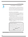
MECHANICAL ADJUSTMENT
[1207 single-mode controllers only]
Five screwdriver-adjustable potentiometers (“trimpots”) allow mechanical adjustment of the main current limit, plug current limit, acceleration rate, maximum creep speed, and maximum speed (labeled “LOW”). The five trimpots are
accessed through holes on the adjustment panel, located under the sliding
protective cover on top of the controller. Adjustments are made with a small
insulated screwdriver.
1
2
1
2
1
2
1
2
1
2
0
3
0
3
0
3
0
3
0
3
OFF
4
OFF
4
OFF
4
OFF
4
OFF
4
MAIN
PLUG
CURRENT L I M I T
ACCEL.
CREEP
L O W
S TAT U S
SPEED L I M I T
The trimpot’s relative position indicates the approximate value over the
allowable range. For example: if the main current limit range is 20–250 amps,
position “0” corresponds to 20 amps, and position “4” to 250 amps. Setting the
pot halfway (at position “2”) corresponds to approximately 135 amps.
If you wish to adjust any of these parameters electronically, using the
programmer, its trimpot must be set to “OFF.”
NOTE: On 1207 controllers with the MultiMode™ feature, the trimpots are
disabled at the factory.
Curtis PMC 1207/1207A Manual
34
41
4 — MAINTENANCE
4
MAINTENANCE
There are no user-serviceable parts inside Curtis PMC 1207 and 1207A controllers. No attempt should be made to open the controller. Opening the
controller may damage it and will void the warranty.
However, it is recommended that the controller exterior be cleaned periodically, and—if a handheld programmer is available—this periodic cleaning provides a good opportunity to check the controller’s diagnostic history file. It is also
recommended that the controller’s fault detection circuitry be checked whenever
the vehicle is serviced.
☞
The 1207/1207A controller is inherently a high power device.
When working around any battery powered vehicle, proper
safety precautions should be taken. These include, but are
not limited to: proper training, wearing eye protection, avoiding loose clothing and jewelry, and using insulated wrenches.
CAUTION
CLEANING
Although the 1207/1207A controller requires virtually no maintenance if properly installed, the following minor maintenance is recommended in certain
applications.
1.
Remove power by disconnecting the battery.
2.
Discharge the capacitors in the controller by connecting a load (such as
a contactor coil or a horn) across the controller’s B+ and B- terminals.
3.
Remove and dirt or corrosion from the bus bar area. The controller
should be wiped clean with a moist rag. Allow it to dry before reconnecting the battery.
4.
Make sure the connections to the bus bars are tight. Use two well
insulated wrenches for this task in order to avoid stressing the bus bars.
DIAGNOSTIC HISTORY
The handheld programmer can be used to access the controller’s diagnostic
history file. Connect the programmer, press the MORE INFO key, and then—while
Curtis PMC 1207/1207A Manual
42
35
4 — MAINTENANCE
continuing to hold the MORE INFO key—press the DIAGNOSTICS key. The programmer will read out all the faults that the controller has experienced since the last
time the diagnostic history file was cleared. The faults may be intermittent faults,
faults caused by loose wires, or faults caused by operator errors. Faults such as
contactor faults may be the result of loose wires; contactor wiring should be
carefully checked out. Faults such as HPD or overtemperature may be caused by
operator habits or by overloading.
After a problem has been diagnosed and corrected, clearing the diagnostic history
file is advisable. This allows the controller to accumulate a new file of faults. By
checking the new diagnostic history file at a later date, you can readily determine
whether the problem was indeed completely fixed.
To clear the diagnostic history file, go to the Special Program Menu (by
pressing and holding the MORE INFO key, and then pressing the PROGRAM key),
scroll through the menu until “Clear Diagnostic History” is the top line in the
display, and then press MORE INFO again. The programmer will prompt you to
acknowledge or cancel. See Section 6 of this manual for more detail on programmer operation.
TESTING THE FAULT DETECTION CIRCUITRY
Specific material handling directives, such as prEN1175, require periodic testing
of the controller’s fault detection circuitry. It is recommended that each time the
vehicle is serviced, the M- fault detection circuitry be checked as follows:
1. Put the vehicle up on blocks to get the drive wheel(s) off the ground,
disconnect the battery, and make sure the keyswitch is off.
2. Using an inline fuse holder fitted with a 10-amp fuse and alligator
clips, connect the controller’s M- and B- terminals.
3. Turn the keyswitch on, release the brake, and apply the throttle. The
motor should not operate, and the direction contactors should not
pull in.
4. Leave the keyswitch on and remove the inline fuse wire. The vehicle
status should continue to remain off.
5. Cycle the keyswitch off and on, release the brake, and apply the
throttle. The vehicle should now operate normally.
Curtis PMC 1207/1207A Manual
36
43
5 — DIAGNOSTICS & TROUBLESHOOTING
5
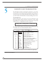
DIAGNOSTICS AND TROUBLESHOOTING
The 1207/1207A controllers provide diagnostics information to assist technicians in troubleshooting drive system problems. The diagnostics information can
be obtained in two ways: reading the appropriate display on the programmer or
observing the fault codes issued by the Status LED. The Status LED is located on
top of the controller. On 1207 models, it is under the sliding protective cover.
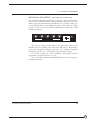
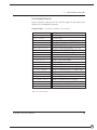
LED DIAGNOSTICS
During normal operation, with no faults present, the Status LED flashes a single
flash at approximately 1 flash/second. If the controller detects a fault, a 2-digit
fault identification code is flashed continuously until the fault is corrected. For
example, code “3,2”—welded direction contactor—appears as:
¤ ¤ ¤ ¤ ¤
(3,2)
¤ ¤ ¤
¤ ¤
(3,2)
¤ ¤ ¤
¤ ¤
(3,2)
The codes are listed in Table 1. For suggestions about possible causes of the
various faults, refer to the troubleshooting chart (Table 2).
Table 1
LED CODE
LED off
solid on
single flash
1,2
1,3
1,4
2,1
2,2
2,3
2,4
3,1
3,2
3,3
3,4
4,1
4,2
4,3
4,4
NOTE:
Curtis PMC 1207/1207A Manual
44
¤
¤ ¤¤
¤ ¤¤¤
¤ ¤¤¤¤
¤¤ ¤
¤¤ ¤¤
¤¤ ¤¤¤
¤¤ ¤¤¤¤
¤¤¤ ¤
¤¤¤ ¤¤
¤¤¤ ¤¤¤
¤¤¤ ¤¤¤¤
¤¤¤¤ ¤
¤¤¤¤ ¤¤
¤¤¤¤ ¤¤¤
¤¤¤¤ ¤¤¤¤
LED CODES
EXPLANATION
no power or defective controller
defective controller
controller operational; no faults
hardware fail-safe error
M- fault or motor output short
sequencing fault (SRO)
5kΩ–0 or throttle wiper input fault
emerg. rev. circuit check fault (BB wiring)
high-pedal-disable fault (HPD)
throttle pot low open or shorted to B+ or Bcontactor or shunt driver overcurrent
welded direction contactor
[reserved for future use]
missing contactor or shunt
low battery voltage
overvoltage
thermal cutback
[reserved for future use]
Only one fault is indicated at a time, and faults are not queued up.
37
5 — DIAGNOSTICS & TROUBLESHOOTING
Operational faults—such as overtemperature—are cleared as soon as operation is
brought within range. Non-operational faults—such as a throttle fault—usually
require the brake or keyswitch to be cycled after the problem is remedied.
PROGRAMMER DIAGNOSTICS
With a programmer, diagnostics and troubleshooting is more direct than with the
LED alone. The programmer presents complete diagnostic information in plain
language—no codes to decipher. Faults are displayed in the Diagnostic Menu,
and the status of the controller inputs/outputs is displayed in the Test Menu.
The following 4-step process is generally used for diagnosing and troubleshooting
an inoperative vehicle: (1) visually inspect the vehicle for obvious problems;
(2) diagnose the problem, using the programmer; (3) test the circuitry with the
programmer; and (4) correct the problem. Repeat the last three steps as necessary
until the vehicle is operational.
Example: A vehicle that does not operate in “forward” is
brought in for repair.
1: Examine the vehicle and its wiring for any obvious
problems, such as broken wires or loose connections.
STEP
2: Connect the programmer, put it in diagnostic mode,
and read the displayed fault information. In this example, the
display shows “No Faults Present,” indicating that the controller has not detected anything out of the norm.
STEP
3: Put the programmer in test mode, and observe the
status of the inputs and outputs in the forward direction. In
this example, the display shows that the forward switch did not
close when “forward” was selected, which means the problem
is either in the forward switch or the switch wiring.
STEP
4: Check or replace the forward switch and wiring and
repeat the test. If the programmer shows the forward switch
closing and the vehicle now drives normally, the problem has
been corrected.
STEP
Refer to the troubleshooting chart (Table 2) for suggestions covering a wide range
of possible faults.
Curtis PMC 1207/1207A Manual
38
45
5 — DIAGNOSTICS & TROUBLESHOOTING
Table 2
LED
CODE
PROGRAMMER
LCD DISPLAY
POSSIBLE CAUSE
1,2
HW F A I L S A F E
hardware fail-safe error
1. Controller defective.
1,3
M - SHOR T ED
M- output shorted
1.
2.
3.
4.
1,4
SRO
SRO fault
1. Improper sequence of KSI, brake, and
direction inputs.
2. Wrong SRO type selected.
3. Brake or direction switch circuit open.
4. Sequencing delay too short.
2,1
THROT T L E F AU L T 1
5kΩ–0 or wiper fault
1.
2.
3.
4.
2,2
BB W I R I NG CHECK
emerg. reverse wiring fault
1. BB wire open.
2. BB check wire open.
2,3
HPD
HPD sequencing fault
1. Improper seq. of KSI, brake, throttle inputs.
2. Wrong HPD type selected.
3. Misadjusted throttle pot.
2,4
THROT T L E F AU L T 2
Pot Low broken or shorted
1. Pot Low wire open.
2. Pot Low wire shorted.
3. Wrong throttle type selected.
3,1
CON T DRVR OC
driver output overcurrent
1. Direction contactor coil shorted.
2. Shunt field shorted.
3,2
3,4
D I R CON T WE L DED
welded direction contactor
1. Direction contactor stuck closed.
M I SS I NG CON T ACTOR
missing contactor or shunt
1.
2.
3.
4.
4,1
L OW BA T T ERY VOL T AGE
low battery voltage
1. Battery voltage <16 volts.
2. Corroded battery terminal.
3. Loose battery or controller terminal.
4,2
OV ERVOL T AGE
overvoltage
1. Battery voltage >48V (1207); >33V (1207A).
2. Vehicle operating with charger attached.
4,3
THERMA L CUT B ACK
over-/under-temp. cutback
1.
2.
3.
4.
Curtis PMC 1207/1207A Manual
46
TROUBLESHOOTING CHART
EXPLANATION
M- output shorted to ground.
Direction contactor not closing.
Direction contactor not closing fast enough.
Internal motor short to ground.
Throttle input wire open.
Throttle input wire shorted to ground or B+.
Throttle pot defective.
Wrong throttle type selected.
Direction contactor coil open.
Direction contactor missing.
Shunt field open.
Wire to shunt or direction contactor open.
Temperature >85°C or <-25°C.
Excessive load on vehicle.
Improper mounting of controller.
Operation in extreme environments.
39
6 — PROGRAMMER OPERATION
6
PROGRAMMER OPERATION
The universal Curtis PMC handheld programmer (optional) allows you to
program, test, and diagnose Curtis PMC programmable controllers. The programmer is powered by the host controller, via an RJ11 modular connector
located in the adjustment panel on top of the controller (1207 models) or via a
4-pin Molex connector on the front panel (1207A models).
When the programmer is first plugged into the controller, it displays the
controller’s model number, date of manufacture, and software revision code.
Following this initial display, the programmer displays a prompt for further
instructions.
+
+
CURTIS PMC
+
+
+
+
++++++++++++++++++++
A 4-line LCD display is
presented in this window
The LED in the corner of
the key lights up to identify
the mode of operation
PROGRAM
Scroll the 4-line
display (up and down)
with these two keys
TEST
SCROLL
DISPLAY
MORE INFO
A DIVISION OF CURTIS INSTRUMENTS INC.
Curtis PMC 1207/1207A Manual
DIAGNOSTICS
CHANGE
VALUE
Choose the Program, Test,
or Diagnostics Mode with
one of these three keys
Change the selected
item’s value (up or down)
with these two keys
Get more information
about selected items with
this key. Also, use this
key in combination with
other keys to put the
programmer in Special
modes.
40
47
6 — PROGRAMMER OPERATION
The programmer is operated via an 8-key keypad. Three keys select operating
modes (Program, Test, Diagnostics), two scroll the display up and down, and two
change the values of selected parameters. The eighth key, the MORE INFO key, is
used to display further information about selected items within any of the three
standard modes. In addition, when pressed together with the PROGRAM or
the DIAGNOSTICS key, the MORE INFO key selects the Special Program mode or the
Special Diagnostics mode.
The display window presents a 4-line LCD display. The display is visible even in
bright sunlight. You can adjust the display contrast in the Special Program mode.
When one of the menu keys is pressed, the LED at the corner of the key lights up,
identifying the mode of programmer operation. For example, if the TEST key is
pressed, the LED at the corner of the key indicates that the programmer is now
in the Test mode, and the Test Menu is displayed.
Four lines of a menu are displayed at a time. The item at the top of the display
window is the selected item. To select an item, scroll within the menu until the
desired item is positioned at the top of the display window. The selected item is
always the top line. (In the Program mode, the selected item is highlighted by a
flashing arrow.) To modify a parameter or obtain more information about it, it
must be scrolled to the top position in the display window.
To scroll up and down within a menu, use the two SCROLL DISPLAY arrow keys.
The SCROLL DISPLAY arrow keys can be pressed repeatedly or be held down. When
a key is held down, the scrolling speed increases the longer the key is held.
SCROLL
DISPLAY
A small scroll bar at the left of the display window provides a rough indication of
the position of the four displayed items within the entire menu. That is, when the
bar is at the top of the window, the top of the menu is displayed. As you scroll
through the menu, the bar moves downward. When the bar is at the very bottom
of the window, you have reached the end of the menu. This sample display is
from the Program Menu:
scroll bar
Curtis PMC 1207/1207A Manual
48
M1
M1
M1
M1
MA I N C / L
P L UG C / L
RAMP C / L
ACCE L RA T E
>250
70
250
1.0
selected item
41
6 — PROGRAMMER OPERATION
CHANGE
VALUE
The two CHANGE VALUE arrow keys are used to increase or decrease the value of a
selected menu item. Like the SCROLL DISPLAY arrow keys, the CHANGE VALUE arrow
keys can be pressed repeatedly or be held down. The longer a key is held, the faster
the parameter changes. This allows rapid changing of any parameter.
An LED on each CHANGE VALUE arrow key indicates whether the key is active
and whether change is permissable. When the value of a parameter is being
increased, the LED on the “up” CHANGE VALUE key is on until you reach the
maximum value for that parameter. When the LED goes off, you cannot increase
the value.
The MORE INFO key has three functions: (1) to display more information about
the selected item, (2) to access the Special Program and Special Diagnostics
modes (when used together with the PROGRAM and DIAGNOSTICS keys), and (3)
to initiate certain commands (such as the Self Test).
“More information” is available in all of the programmer operating modes.
After using the MORE INFO key to display additional information about the
selected item, press the MORE INFO key again to return to the original list.
OPERATING MODES:
PROGRAM, TEST, DIAGNOSTICS, SPECIAL PROGRAM, SPECIAL DIAGNOSTICS
PROGRAM
In the Program mode, accessed by pressing the PROGRAM key, all the adjustable
parameters and features of the controller are displayed (four at a time), along with
their present settings. The setting of the selected item—the item at the top of the
display, with the flashing arrow—can be changed, using the two CHANGE VALUE
keys.
The LEDs on these keys indicate whether there is still room for change. That
is, when the upper limit of a parameter’s range is reached, the LED on the “up”
key no longer lights up, indicating that the present value cannot be increased;
when the lower limit is reached, the LED on the “down” key no longer lights up.
The MORE INFO key, when used in the Program mode, displays a bar graph
along with the minimum and maximum values possible for the selected parameter. Parameters can be changed either from the main Program Menu or after
the MORE INFO key has been pressed and the additional information is being
displayed (see example below).
selected parameter
bar graph
minimum value
MODE 1 ACCE L ERA T I ON
RA T E , SECS
MIN 0 . 2
set value
1.3
MAX 3 . 0
maximum value
units
Curtis PMC 1207/1207A Manual
42
49
6 — PROGRAMMER OPERATION
Some parameters on some controllers have dependencies on other parameters. This means that the available settings for one parameter may be dependent
on the limits of another parameter. If you attempt to set a parameter (A) outside
the limits imposed by another parameter (B), a message will be displayed
indicating that parameter A is dependent on parameter B.
The Program Menu is presented at the end of this section. NOTE: Some items
may not be available on all models.
TEST
DIAGNOSTICS
*
MORE INFO
PROGRAM
In the Test mode, accessed by pressing the TEST key, real-time information is
displayed about the status of the inputs, outputs, and controller temperature. For
example, when the status of the forward switch is displayed, it should read
“On/Off/On/Off/On/Off” as the switch is repeatedly turned on and off. In the
Test mode, the item of interest does not need to be the top item on the list; it only
needs to be among the four items visible in the window. The Test mode is useful
for checking out the operation of the controller during initial installation, and
also for troubleshooting should problems occur.
The MORE INFO key, when used in the Test mode, causes additional information to be displayed about the selected item (top line in the window).
The Test Menu is presented at the end of this section. NOTE: Some items may
not be available on all models.
In the Diagnostics mode, accessed by pressing the DIAGNOSTICS key, currently
active faults detected by the controller are displayed.
The MORE INFO key, when used in the Diagnostics mode, causes additional
information to be displayed about the selected item.
A list of the abbreviations used in the Diagnostics display is included at the
end of this section.
The Special Program mode allows you to perform a variety of tasks, most of
which are self-explanatory. Through the Special Program Menu, you can revert
to earlier settings, save controller settings into the programmer memory, load the
controller settings from the programmer into a controller, clear the controller’s
diagnostic history, adjust the contrast of the programmer’s LCD display, select
the language to be displayed by the programmer, and display basic information
(model number, etc.) about the controller and the programmer.
To access the Special Program mode, first press the MORE INFO key. Then,
while continuing to hold the MORE INFO key, press the PROGRAM key. The LED
on the PROGRAM key will light, just as when the programmer is in Program mode.
Curtis PMC 1207/1207A Manual
50
43
6 — PROGRAMMER OPERATION
To distinguish between the Program and Special Program modes, look at the
menu items in the display.
CONTROLLER CLONING
Two of the Special Program Menu items—“Save Controller
Settings in Programmer” and “Load Programmer Settings
into Controller”—allow you to “clone” controllers. To do
this, simply program one controller to the desired settings,
save these settings in the programmer, and then load them
into other similar (same model number) controllers, thus
creating a family of controllers with identical settings.
The MORE INFO key is used initially to access the Special Program mode, and once
you are within the Special Program mode, it is used to perform the desired tasks.
To adjust the contrast in the display window, for example, select “Contrast
Adjustment” by scrolling until this item is at the top of the screen, and then
press MORE INFO to find out how to make the adjustment.
The Special Program Menu is presented at the end of this section.
*
MORE INFO DIAGNOSTICS
In the Special Diagnostics mode, the controller’s diagnostic history file is
displayed. This file includes a list of all faults observed and recorded by the
controller since the history was last cleared. (NOTE: The maximum and minimum
temperatures recorded by the controller are included in the Test Menu.) Each
fault is listed in the diagnostic history file only once, regardless of the number of
times it occurred.
To access Special Diagnostics, first press the MORE INFO key. Then, while
continuing to hold the MORE INFO key, press the DIAGNOSTICS key. The LED on
the DIAGNOSTICS key will light, just as when the programmer is in Diagnostics
mode.
The MORE INFO key, when used within the Special Diagnostics mode, causes
additional information to be displayed about the selected item.
To clear the diagnostic history file, put the programmer into the Special
Program mode, select “Clear Diagnostic History,” and press the MORE INFO key
for instructions. Clearing the diagnostic history file also resets the maximum/
minimum temperatures in the Test Menu.
Curtis PMC 1207/1207A Manual
44
51
6 — PROGRAMMER OPERATION
PEACE-OF-MIND PROGRAMMING
Each time the programmer is connected to the controller, it acquires all the
controller’s parameters and stores them in its temporary memory. You can revert
back to these original settings at any time during a programming session via the
Special Program Menu. Select “Reset All Settings” by scrolling it to the top of the
display window, press the MORE INFO key, and follow the instructions displayed.
Any inadvertent changing of parameters can be “undone” using this procedure—
even if you can’t remember what the previous settings were—as long as the
programmer has not been unplugged and power has not been removed from
the controller.
Programmer Self Test
You can test the programmer by displaying two special test screens. Press
the MORE INFO key while the programmer is powering up. During the Self Test,
you can toggle between the two test screens by pressing the SCROLL DISPLAY keys.
The first screen turns on every LCD element, and the second screen displays all
the characters used in the various menus. As part of the Self Test, you can also test
the keys be pressing each one and observing whether its corner LED lights up. To
exit the Self Test, unplug the programmer or turn off the controller, and then repower it without holding the MORE INFO key.
⇐
SCROLL
DISPLAY
⇒
Curtis PMC 1207/1207A Manual
52
! " # $%& ' ( ) * + , - . /
0 123 45 6 789 : ; <= >?
@A B C D E FG H I J K L M NO
P Q R S T U VWX Y Z x > Ω°
45
6 — PROGRAMMER OPERATION
PROGRAMMER MENUS
Items are listed for each menu in the order they appear in the actual menus
displayed by the handheld programmer.
Program Menu
EMR
R E V
C / L
T HROT T L E
R AMP
T Y P E
SH A P E
CRE E P
EMR
(not all items available on all controllers)
S P E ED
R E V
S P E ED
S EQU ENC I NG
V AR I A B L E
H I GH
D L Y
P L UG
P ED A L
D I S
SRO
A N T I - T I E DOWN
QU I C K
S T AR T
M1
MA I N
C / L
M1
P L UG
C / L
M1
R AMP
C / L
M1
ACCE L
M1
MA X
M2
MA I N
C / L
M2
P L UG
C / L
M2
R AMP
C / L
S P E ED
M2
ACCE L
M2
MA X
N EU T
RA T E
RA T E
S P E ED
BRA K E
N EU T R A L
C / L
BRA K E
Emergency reverse current limit
Throttle type*
Throttle map
Creep speed, as percent PWM duty cycle
Emerg. reverse speed, as % PWM duty cycle
Sequencing delay, in seconds
Throttle-variable plug braking: on or off
High pedal disable (HPD): type†
Static return to off (SRO): type‡
Anti-tiedown: on or off
Quick-start throttle factor
Mode 1 main current limit
Mode 1 plug current limit
Mode 1 ramp start current limit
Mode 1 acceleration rate, in seconds
Mode 1 maximum speed, as % PWM output
Mode 2 main current limit
Mode 2 plug current limit
Mode 2 ramp start current limit
Mode 2 acceleration rate, in seconds
Mode 2 maximum speed, as % PWM output
Neutral brake current limit
Neutral brake: on or off
(Notes are on the next page.)
Curtis PMC 1207/1207A Manual
46
53
6 — PROGRAMMER OPERATION
Program Menu Notes
(For more detail on these options, see Appendix A: Glossary of Features and Functions.)
* Throttle types
Type 1: 5kΩ–0
Type 2: 0–5V, 0–10V, 3-wire pot, and electronic throttles
Type 3: 0–5kΩ throttles
† HPD types
Type 0: no HPD
Type 1: HPD on brake input
Type 2: HPD on KSI
‡ SRO types
Type 0:
Type 1:
Type 2:
Type 3:
no SRO
SRO on brake input
SRO on KSI plus brake input plus a direction input
SRO on KSI plus brake input plus forward input
Test Menu
(not all items available on all controllers)
T HROT T L E
%
B A T T
VO L T AGE
H E A T
S I N K
° C
MA X
T EMP
° C
M I N
T EMP
° C
BRA K E
I N PU T
S P E ED
I N
EMR
R E V
I NPU T
F ORWA R D
I NPU T
R E V ER S E
I NPU T
MA I N
CON T AC TOR
FWD
CON T
R E V
CON T
Throttle reading, as percent of full
Battery voltage
Heatsink temperature
Maximum temperature seen *
Minimum temperature seen *
Brake switch: on/off
Mode switch: on (Mode 1) / off (Mode 2)
Emergency reverse switch: on/off
Forward switch: on/off
Reverse switch: on/off
Main contactor: on/off
Forward contactor: on/off
Reverse contactor: on/off
* Maximum/minimum temperatures recorded
since Diagnostic History was last cleared.
Curtis PMC 1207/1207A Manual
54
47
6 — PROGRAMMER OPERATION
Special Program Menu
R E S E T
A L L
S E T T I NGS
CON T
S E T T I NGS >
PROG
PROG
S E T T I NGS >
CON T
C L E AR
D I AG
H I S TOR Y
CON T R A S T
AD J U S TMEN T
L ANGU AGE
S E L EC T I ON
P ROGR AMME R
I N F O
CON T RO L L ER
I N F O
Revert to original settings
Save controller settings in programmer
Load programmer settings in controller
Clear diagnostic history memory
Adjust display contrast
Select displayed language
Display programmer information
Display controller information
Diagnostics and Special Diagnostics
“ Menu ”
This is not a menu as such, but simply a list of the possible messages you may see
displayed when the programmer is operating in either of the Diagnostics modes.
The messages are listed in alphabetical order for easy reference.
B B
W I R I NG
CON T
D I R
CH ECK
DRVR
CON T
OC
WE L D E D
H PD
HW
L OW
M -
F A I L S A F E
B A T T ERY
SHOR T ED
M I S S I NG
NO
VO L T AGE
K NOWN
CON T AC TOR
F AU L T S
OV ER VO L T AGE
SRO
T HERMA L
CU T B ACK
T HROT T L E
F AU L T 1
T HROT T L E
F AU L T 2
Curtis PMC 1207/1207A Manual
BB wiring check failed
Contactor driver overcurrent
Direction contactor welded
High-pedal-disable (HPD) activated
Hardware failsafe activated
Low battery voltage (<16V)
M- output fault
Missing contactor
No known faults
Overvoltage (1207: >48V; 1207A: >33V)
Static-return-to-off (SRO) activated
Cutback, due to over/under temp
Throttle input fault
Throttle low input fault
48
55
APPENDIX A: GLOSSARY
APPENDIX A
GLOSSARY OF FEATURES AND FUNCTIONS
Acceleration/deceleration rate
The acceleration rate is the time required for the controller to increase from 0%
to 100% duty factor. The shape of the acceleration curve is controlled by the
dynamic throttle response, which is linear.
If you have a MultiMode™ controller, the acceleration rates in Mode 1 and
in Mode 2 are independently adjustable via the handheld programmer. If you
have a 1207 controller with the MultiMode™ feature disabled (i.e., a singlemode controller), you can adjust the acceleration rate mechanically via the
appropriate trimpot located on top of the controller.
Anti-tiedown
Before enabling Mode 1 operation, the anti-tiedown function checks that the
mode selection switch has been released after the last cycling of the brake switch.
This feature discourages operators from taping or otherwise “tying down” the
mode switch. If Mode 1 is already selected before the brake is released, the
controller remains in Mode 2 until the mode switch is released and pressed again.
Arcless contactor switching
The controller output duty factor is quickly reduced to zero any time a direction
is de-selected, so that the controller current will be reduced to zero before the
direction contactor drops out.
BB (= Belly Button; see Emergency reverse)
Brake
The brake must be released (brake input “high”) for the controller to operate.
This is a safety interlock used on most material handling vehicles.
Cycling the brake or KSI clears most faults and enables operation.
Curtis PMC 1207/1207A Manual
56
A-1
APPENDIX A: GLOSSARY
Contactor drivers and circuits
These controllers can accommodate up to four external contactors: forward,
reverse, main, and shunt. Some vehicles may have no main contactor, or the main
contactor may be wired directly to the KSI or brake signal, bypassing the
controller.
Various protections provided for the contactor drivers ensure that the
contactors operate correctly; see Fault detection.
The shunt winding of a compound motor can be wired directly to the shunt
driver, provided that the maximum current does not exceed the driver’s current
rating.
Creep speed at first throttle
Creep speed is activated when a direction is first selected. The output maintains
creep speed until the throttle is rotated out of the throttle deadband (typically
10% of throttle). Creep speed is adjustable from 0 to 25% of the controller duty
factor; the adjustment can be made mechanically (via the appropriate trimpot on
top of the 1207 controller) or electronically (via the handheld programmer).
Current limiting
Curtis PMC controllers limit the motor current to a preset maximum. This
feature protects the controller from damage that might result if the current were
limited only by motor demand. PWM output to the power section is reduced
smoothly until the motor current falls below the set limit level.
In addition to protecting the controller, the current limit feature also
protects the rest of the system. By eliminating high current surges during vehicle
acceleration, stress on the motor and batteries is reduced and their efficiency
enhanced. Similarly, there is less wear and tear on the vehicle drivetrain, as well
as on the ground on which the vehicle rides (an important consideration with golf
courses and tennis courts, for example).
If you have a MultiMode™ controller, the main current limit, plug current
limit, and ramp start current limit in Mode 1 and in Mode 2 are independently
adjustable via the handheld programmer. If you have a 1207 controller with the
MultiMode™ feature disabled (i.e., a single-mode controller), you can adjust the
main and plug current limits mechanically via the appropriate trimpots located
on top of the controller.
In addition, the emergency reverse current limit can be set via the handheld
programmer.
Curtis PMC 1207/1207A Manual
A-2
57
APPENDIX A: GLOSSARY
Current multiplication
During acceleration and during reduced speed operation, the Curtis PMC
controller allows more current to flow into the motor than flows out of the
battery. The controller acts like a dc transformer, taking in low current and high
voltage (the full battery voltage) and putting out high current and low voltage.
The battery needs to supply only a fraction of the current that would be required
by a conventional controller (in which the battery current and motor current are
always equal). The current multiplication feature gives vehicles using Curtis
PMC controllers dramatically greater driving range per battery charge.
Deceleration rate
The deceleration rate is the time required for the controller to decrease from
100% duty factor to zero. The deceleration rate is fixed, and cannot be adjusted.
The shape of the deceleration curve is controlled by the dynamic throttle
response, which is linear.
Emergency reverse
Emergency reverse is activated when the brake is released, KSI is activated, and
the emergency reverse switch (the BB, or “belly button” switch) is pressed. After
the BB switch is released, normal controller operation is not resumed until
neutral (no direction) is selected or until the brake is cycled (brake, then brake
release). However, repeatedly pressing the BB switch will reactivate the emergency reverse function each time.
Because emergency reverse immediately powers the reverse contactor, some
arcing may occur.
Fault detection
An internal microcontroller automatically maintains surveillance over the functioning of the controller. When a fault is detected, the appropriate fault code is
signalled via the LED, externally visible on top of the controller. The diagnostic
codes flashed by the LED are listed in Section 5, Troubleshooting.
If the fault is critical, the controller is disabled. More typically, the fault is a
remediable condition and temporary—for example, an undervoltage fault is
cleared when the condition is removed.
Curtis PMC 1207/1207A Manual
58
A-3
APPENDIX A: GLOSSARY
The automatic fault detection system includes:
contactor coil open / shorted driver (F/R and shunt contactors)
contactor driver overcurrent / contactor coil short
contactor welded
emergency reverse circuit check
M- output fault
memory checks upon start-up
overvoltage cutoff
power supply out of range (internal)
throttle fault
undervoltage cutback
watchdog (external and internal)
watchdog (internal)
Fault recording
Fault events are recorded in the controller’s memory. Multiple occurrences of the
same fault are recorded as one occurrence.
The fault event list can be loaded into the programmer for readout. The
Special Diagnostics mode provides access to the controller’s diagnostic history
file—the entire fault event list created since the diagnostic history file was last
cleared. The Diagnostics mode, on the other hand, provides information about
only the currently active faults.
Fault recovery
(including recovery from disable)
Almost all faults require a cycling of the KSI or brake input to reset the controller
and enable operation.
The only exceptions are these:
Curtis PMC 1207/1207A Manual
FAULT
RECOVERY
anti-tiedown
contactor overcurrent
emergency reverse
HPD
overvoltage
SRO
thermal cutback
throttle fault
undervoltage
release and re-select Mode 1
when condition clears
BB re-applied or brake cycled
lower throttle to below HPD threshold
when battery voltage drops below overvoltage
when proper sequence is followed
when temperature comes within range
clears when condition gone
when battery voltage rises above undervoltage
A-4
59
APPENDIX A: GLOSSARY
High-pedal-disable (HPD)
The HPD feature prevents the vehicle from being started while the throttle is
applied. The controller can be programmed to have HPD based on either brake
input or KSI.
Brake-type HPD
To start the vehicle, the controller must receive a brake input (brake released)
before receiving a throttle input. Controller operation will be disabled immediately if pedal demand (throttle input) is greater than 25% duty factor at the time
the brake is released (brake input “high”). Normal controller operation is regained by reducing the throttle demand to less than 25%.
Sequencing delay, which can be set with the handheld programmer, provides
a variable delay before disabling the controller. If the brake is applied while the
throttle is above the HPD threshold (25%), HPD is not activated if the brake is
then released before the delay time elapses.
KSI-type HPD
The HPD feature can be activated by KSI input instead of brake input, if
preferred. To start the vehicle, the controller must receive a KSI input before
receiving a throttle input.
KSI
KSI (Key Switch Input) provides power to the logic board, and initializes and
starts diagnostics. In combination with the brake input, KSI enables all logic
functions.
Some vehicles may have no keyswitch (KSI simply tied to B+) or may have
the key permanently turned on.
LED
A Status LED located on top of the controller flashes a fault identification code
if a fault is detected by the controller. The fault codes are listed in Table 1. The
code will continue to flash until the fault condition has been cleared during active
fault detection. This will typically happen after cycling KSI for power-up fault
conditions, and cycling the brake for faults detected during operation. NOTE: In
1207 models, the Status LED is on the adjustment panel under the sliding
protective cover.
Curtis PMC 1207/1207A Manual
60
A-5
APPENDIX A: GLOSSARY
MOSFET
A MOSFET (Metal Oxide Semiconductor Field Effect Transistor) is a type of
transistor characterized by its fast switching speeds and very low losses.
MultiMode ™
The MultiMode™ feature of these controllers allows the vehicle to be operated
with two distinct sets of characteristics. The two modes can be programmed to be
suitable for operation under different conditions, such as slow precise maneuvering in Mode 2 and faster, long distance travel in Mode 1. The following
parameters can be set independently in the two modes:
— main current limit
— plug current limit
— ramp start current limit
— acceleration rate
— maximum speed
The operating mode is selected by means of the mode selection switch. If
Mode 1 is not selected, the controller operates by default in Mode 2. When the
controller returns to Mode 2 from Mode 1, it automatically changes the main
current limit, the plug current limit, the ramp start current limit, the acceleration
rate, and the maximum speed to their Mode 2 values.
If the anti-tiedown feature is active, Mode 1 must be re-selected each time
the brake is released.
Neutral brake
The optional neutral brake feature provides automatic plug braking in neutral. If
this option is not selected, the vehicle is free to coast in neutral. The neutral brake
plug current limit is programmable.
Overtemperature
At overtemperature (from 85°C to 95°C), the drive current limit is linearly
decreased from full set current down to zero. (Plug current, however, is not
reduced—in order to provide full vehicle braking under all thermal conditions.)
The operating PWM frequency is shifted to 1.5 kHz when the controller is
operating in the overtemperature range.
Overvoltage protection
Overvoltage resets the microprocessor, inhibits PWM, and opens the contactors,
thereby shutting down the controller. Overvoltage can result during battery
charging or from an improperly wired controller. Controller operation resumes
Curtis PMC 1207/1207A Manual
A-6
61
APPENDIX A: GLOSSARY
when the voltage is brought within the acceptable range. The cutoff voltage and
re-enable voltage are percentages of the battery voltage, and are set at the factory.
Plug braking
Plug braking takes place when a series motor is driven electrically in a direction
opposite from the direction it is turning. The 1207/1207A controls the field
current to obtain smooth and controlled plug braking torque. During plug
braking, the maximum current limit is automatically changed to the plug current
limit, and the PWM frequency is changed to 1.5 kHz. NOTE: Plug current limit
on the 1207/1207A controls the field current. The armature current in plug
mode will be higher than the field current.
There are two types of plug braking control — fixed and variable. The fixed
plug current limit is set to a fixed level. The variable plug current limit varies the
current limit to correspond to the throttle position.
If you have a MultiMode™ controller, the plug current limits in Mode 1
and in Mode 2 are independently adjustable via the handheld programmer. If you
have a 1207 controller with the MultiMode™ feature disabled (i.e., a singlemode controller), you can adjust the plug current limit mechanically via the
appropriate trimpot located on top of the controller.
PWM
Pulse width modulation (PWM), also called “chopping,” is a technique that
switches battery voltage to the motor on and off very quickly, thereby controlling
the speed of the motor. Curtis PMC 1200 series controllers use high frequency
PWM—15 kHz—which permits silent, efficient operation.
Quick-start
Upon receiving a quick throttle demand from neutral, the controller will exceed
normal acceleration momentarily in order to overcome inertia. The “quick-start”
algorithm is applied each time the vehicle passes through neutral and is not in
plug mode. If the vehicle is in plug, the quick-start function is disabled, allowing
normal plug braking to occur.
The quick-start throttle factor is adjustable via the handheld programmer.
Ramp shape (throttle map)
“Ramp shape” is a programmable parameter that determines the static throttle
map of the 1207/1207A controller. Eleven preprogrammed ramp shapes are
available, in 5% steps between 20% and 70% (20, 25, 30, 35, 40, 45, 50, 55, 60,
Curtis PMC 1207/1207A Manual
62
A-7
APPENDIX A: GLOSSARY
65, and 70%). The ramp shape number refers to the PWM output at half
throttle, as a percentage of its full range. For example, if maximum speed is set at
100% and creep speed is set at 0, a ramp shape of 50% will give 50% output at
half throttle. The 50% ramp shape corresponds to a linear response. The six “even
number” ramp shapes for maximum and creep speeds set at 100% and 0 are
shown in Figure A-1.
Fig. A-1 Ramp shape
(throttle map) for controller with maximum speed
set at 100% and creep
speed set at 0.
100
RAMP SHAPE
MAXIMUM SPEED (100%)
90
70%
60%
80
50%
40%
PWM (percent)
70
30%
60
20%
50
40
30
CREEP
SPEED
(0)
20
10
0
0
10
20
30
40
50
60
70
80
90
100
THROTTLE (percent)
Changing either the maximum speed setting or the creep speed setting changes
the output range of the controller. Ramp shape output is always a percentage of
that range. Ramp shapes with the creep speed setting raised to 10% are shown in
Figure A-2.
Fig. A-2 Ramp shape
(throttle map) for controller with maximum speed
set at 100% and creep
speed set at 10%.
100
RAMP SHAPE
MAXIMUM SPEED (100%)
90
70%
60%
80
50%
40%
PWM (percent)
70
30%
60
20%
50
40
30
20
10
CREEP SPEED (10%)
0
0
10
20
30
40
50
60
70
80
90
100
THROTTLE (percent)
Curtis PMC 1207/1207A Manual
A-8
63
APPENDIX A: GLOSSARY
In Figure A-3, the creep speed is kept at 10% and the maximum speed setting
dropped to 60%.
Fig. A-3 Ramp shape
(throttle map) for controller with maximum speed
set at 60% and creep speed
set at 10%.
100
RAMP SHAPE
90
70%
60%
80
50%
MAXIMUM SPEED
(60%)
PWM (percent)
70
40%
30%
60
20%
50
CREEP SPEED
(10%)
40
30
20
10
0
0
10
20
30
40
50
60
70
80
90
100
THROTTLE (percent)
In all cases, the ramp shape number is the PWM output at half throttle, as a
percentage of its full range. So, for example, in Figure A-3, a 50% ramp shape
gives 35% PWM output at half throttle (halfway between 10% and 60%). A 30%
ramp shape gives 25% PWM at half throttle (30% of the range {which is 50%,
from 10% to 60%}, starting at 10% output, or {[.30 x 50%] + 10%} = 25%).
Ramp start
The ramp start feature allows the vehicle to be started with a higher plug current
limit to prevent rolling downhill. Ramp start increases the plug current limit for
the selected direction only. When the opposite direction is selected, ramp start
will be canceled and a 3-step sequence must be followed to re-activate it:
STEP 1. select a direction for more than 1 second,
STEP 2. return to neutral, and
STEP 3. re-select the same direction.
Once the vehicle is operating in ramp start mode, it will continue to do so until
the opposite direction is selected for more than one second.
When the brake is first released, the ramp start current limit level will be
obtained when either direction is selected in plug braking mode. In ramp start
mode, either direction selected will allow the ramp start current limit level. This
condition remains until the other direction is selected for more than one second.
The new direction then becomes the decision direction, and the 3-step ramp start
sequence is required to regain the ramp start current limit level in plug.
Curtis PMC 1207/1207A Manual
64
A-9
APPENDIX A: GLOSSARY
The ramp start current limit is adjustable via the handheld programmer. The
Mode 1 and Mode 2 ramp start current limits can be set independently.
Reset
Almost all faults require a cycling of the KSI or brake input to reset the controller
and enable operation; see Fault recovery for exceptions.
Sequencing delay
Sequencing delay allows the brake to be cycled within a set time (the sequencing
delay), in order to prevent inadvertent activation of HPD or SRO. This feature
is useful in applications where the brake switch may bounce or be momentarily
cycled during operation. The delay can be set with the handheld programmer
from 0 to 3 seconds, where 0 corresponds to no delay.
Shunt field control
The shunt field of a compound motor can be directly controlled by using the
shunt winding driver (if the current requirement meets the contactor driver
specifications). The shunt is activated while a direction is selected, as long as the
controller is not in plug braking mode. A programmable delay is available for the
shunt drive. This delays the shunt turn-on until some time after the reversing
contactors have shuttled. The delay can be set with the handheld programmer
from 0 to 0.5 seconds, where 0 corresponds to no delay.
Smooth, stepless operation
Like all Curtis PMC 1200 Series controllers, the 1207 and 1207A models allow
superior operator control of the vehicle’s drive motor speed. The amount of
current delivered to the motor is set by varying the “on” time (duty cycle) of the
controller’s power MOSFET transistors. This technique—pulse width modulation (PWM)—permits silent, stepless operation.
Speed settings
The maximum speed setting defines the upper-limit speed as a percentage of
PWM output at full throttle. If you have a MultiMode™ controller, the
maximum speed settings in Mode 1 and in Mode 2 are independently adjustable
via the handheld programmer. If you have a 1207 controller with the MultiMode™
Curtis PMC 1207/1207A Manual
A-10
65
APPENDIX A: GLOSSARY
feature disabled (i.e., a single-mode controller), you can adjust the maximum
speed mechanically via the trimpot labeled “LOW” on top of the controller.
The maximum creep speed setting is also adjustable via these two methods;
see Creep speed. The maximum emergency reverse speed is adjustable only via the
programmer.
Static-return-to-off (SRO)
The SRO feature prevents the vehicle from being started when “in gear.” SRO
checks the sequencing of brake input—or of KSI and brake input—relative to a
direction input. The brake input must come on before a direction is selected. If
a direction is selected before or simultaneously (within 50 msec) with the brake
input, the controller is disabled. There are three types of SRO: SRO relative to
brake input alone (Type “1” in the programming menu); SRO relative to both
KSI and brake input (Type “2”); and SRO relative to KSI, brake, and forward
inputs (Type “3”). The handheld programmer can be used to set the controller to
operate with any of these types of SRO, or with no SRO (SRO Type “0”).
If your controller is programmed so that both KSI and brake input are
required (SRO Type “2”), the following sequence must be followed to enable the
controller: STEP 1, KSI on; STEP 2, brake released (brake input “high”); and STEP 3,
direction selected. The interval between steps 1 and 2 is the same as between steps
2 and 3; that is, KSI input must precede brake input by at least 50 msec. Once
the controller is operational, turning off either KSI or the brake causes the
controller to turn off; re-enabling the controller requires the 3-step sequence.
Similarly, if your controller is programmed so that KSI, brake, and forward
inputs are all required (SRO Type “3”), they must be provided in that sequence
in order to enable the controller. Note, however, that operation is allowed if a
reverse input precedes the brake input; this can be useful when operating a walkie
on ramps.
Sequencing delay, which can be set with the handheld programmer, provides
a variable delay before disabling the controller. If the brake is applied while
direction is selected, SRO is not activated if the brake is then released before the
delay time elapses.
Temperature compensation for current limits
Full temperature compensation provides constant current limits throughout the
normal operating range (heatsink temperatures of -25°C to +85°C). The temperature sensor is also used to calculate and display the heatsink temperature on
the handheld programmer.
Curtis PMC 1207/1207A Manual
66
A-11
APPENDIX A: GLOSSARY
Temperature extreme current-limit cutback
Undertemperature)
(see Overtemperature,
Temperature extreme data storage
The maximum and minimum temperatures read at the heatsink at any time
during powering of the controller are stored in the controller’s memory. These
values (which can be accessed via the programmer’s Test Menu) are cleared each
time the controller’s diagnostic history file is cleared.
Throttle map
The throttle map (duty factor as a function of throttle position) is adjustable, so
that you can provide the proper feel for the many types of vehicles that use the
1207 controller. The throttle map parameter is called “ramp shape”; see Ramp
shape for more information.
Throttle response
The dynamic throttle response (duty factor as a function of time) is shaped by the
acceleration rate setting. Dynamic throttle response is linear. The newest throttle
input is mapped to the throttle map, and the controller then automatically
accelerates (or decelerates) through a straight line until the new throttle demand
is obtained.
Throttle types
The 1207 and 1207A controllers accept a variety of throttle inputs, through
various combinations of their four throttle input pins. The most commonly used
throttles can all be hooked up directly: 5kΩ–0 and 0–5kΩ 2-wire rheostats,
3-wire pots, 0–5V throttles, 0–10V throttles (1207 only), and the Curtis
ET-XXX electronic throttle.
Throttle full range produces 0–100% duty factor at the controller output
(unless limited by other conditions). Throttle fault detect is performed on the
throttle input signals and virtually eliminates the possibility of runaway operation. Adjustments and settings are independent of throttle type. However,
throttle fault conditions will vary by throttle type.
Curtis PMC 1207/1207A Manual
A-12
67
APPENDIX A: GLOSSARY
Undertemperature
When the controller is operating at less than -25°C, the current limit is cut back
to approximately one-half of the set current. The operating PWM frequency is
shifted to 1.5 kHz when the controller is operating at undertemperature.
Undervoltage protection
Undervoltage protection automatically disables the controller output if battery
voltage is detected below the undervoltage point at start-up, or when the battery
voltage is pulled below the undervoltage point by an external load. The undervoltage
cutback point is set in ROM, and is not adjustable.
During normal operation, the controller duty factor will be reduced when
the batteries discharge down to less than the undervoltage level. If the motor
current is such that the batteries are being pulled below the minimum point, the
duty factor will be reduced until the battery voltage recovers to the minimum
level. In this way the controller “servos” the duty factor around the point which
maintains the minimum allowed battery voltage.
If the voltage continues to drop below the undervoltage level to a severe
undervoltage condition (due to battery drain or external load), the controller
continues to behave in a predictable fashion, with its output disabled.
Watchdog (external, internal)
The external watchdog timer guards against a complete failure of the microprocessor, which would incapacitate the internal watchdog timer. This independent
system check on the microprocessor meets the EEC’s requirement for backup
fault detection.
The external watchdog timer safety circuit shuts down the controller (and
the microprocessor) if the software fails to generate a periodic external pulse train.
This pulse train can only be created if the microprocessor is operating. If not
periodically reset, the watchdog timer times out after 150 msec and turns off the
controller. The external watchdog also directly disengages all contactors and
directly shuts down the PWM drive to the MOSFETs. It can only be reset by
cycling KSI.
The internal watchdog timer must be reset periodically by correct sequential
execution of the software. If not reset, the internal timer times out and the
microprocessor is “warm booted.” This causes the microprocessor to shut down
its outputs (thus shutting down the controller) and attempt to restart.
Curtis PMC 1207/1207A Manual
68
A-13
APPENDIX
APPENDIX
B: SPECIFICATIONS
A: GLOSSARY
APPENDIX B
SPECIFICATIONS
Table B-1
SPECIFICATIONS: 1207 CONTROLLERS
Nominal input voltage range
Maximum operating voltage
Overvoltage point
Minimum operating voltage
Electrical isolation to heatsink
PWM operating frequency
24 – 36 V
45 V
48 V
16 V (= undervoltage point)
500 V ac (minimum)
15 kHz
Output current*
250
200
150
100
1207-11XX
amps for 1 minute
amps for 2 minutes
amps for 5 minutes
amps for 1 hour
300
210
160
110
1207-21XX
amps for 30 seconds
amps for 2 minutes
amps for 5 minutes
amps for 1 hour
Contactor voltage
Contactor current (maximum)
Contactor coil spike protection
Shunt driver current (maximum)
Shunt driver spike protection
= battery voltage
1 amp (current limit at 2 amps)
internal diode to brake; internal diode from brake to KSI
2 amps
active clamp at 47 V
KSI input voltage
KSI input current (typical)
Logic input current (typical)
Logic input threshold
16 – 45 V
80 mA without programmer; 130 mA with programmer
10 mA at 24 V
8V
Ambient operating temperature range
Heatsink overtemperature cutback
Heatsink undertemperature cutback
-25°C to 50°C
85°C
-25°C
Package
Weight
Dimensions
splash resistant
1.1 kg (2.5 lbs)
122 × 165 × 60 mm (4.8" × 6.5" × 2.35")
* Output current rating test conditions:
1.
2.
3.
4.
5.
6.
7.
Controller cover installed
Controller mounted to 230 × 305 × 3.2 mm (9" × 12" × 0.125") aluminum plate heatsink
Airflow at 4.8 km/h (3 mph) perpendicular to bottom of aluminum plate
Duty factor held at 60%
Initial heatsink temperature at 20°C
Ambient temperature at 20°C
Current held at tested rating for 120% of time before thermal cutback
Curtis PMC 1207/1207A Manual
A-14
B-1
69
APPENDIX
APPENDIX
B: SPECIFICATIONS
A: GLOSSARY
Table B-2
SPECIFICATIONS: 1207A CONTROLLERS
Nominal input voltage
Maximum operating voltage
Overvoltage point
Minimum operating voltage
Electrical isolation to heatsink
PWM operating frequency
24 V
30 V
33 V
16 V (= undervoltage point)
500 V ac (minimum)
15 kHz
Output current*
250
200
150
100
1207A-41XX
amps for 1 minute
amps for 2 minutes
amps for 5 minutes
amps for 1 hour
300
210
160
110
1207A-51XX
amps for 30 seconds
amps for 2 minutes
amps for 5 minutes
amps for 1 hour
Contactor voltage
Contactor current (maximum)
Contactor coil spike protection
Shunt driver current (maximum)
Shunt driver spike protection
24 V
1 amp (current limit at 2 amps)
internal diode to brake; internal diode from brake to KSI
2 amps
active clamp at 47 V
KSI input voltage
KSI input current (typical)
Logic input current (typical)
Logic input threshold
16 – 30 V
80 mA without programmer; 130 mA with programmer
10 mA at 24 V
8V
Ambient operating temperature range
Heatsink overtemperature cutback
Heatsink undertemperature cutback
-25°C to 50°C
85°C
-25°C
Package
Weight
Dimensions
splash resistant
1.1 kg (2.5 lbs)
122 × 165 × 66 mm (4.8" × 6.5" × 2.6")
* Output current rating test conditions:
1.
2.
3.
4.
5.
6.
7.
Controller cover installed
Controller mounted to 230 × 305 × 3.2 mm (9" × 12" × 0.125") aluminum plate heatsink
Airflow at 4.8 km/h (3 mph) perpendicular to bottom of aluminum plate
Duty factor held at 60%
Initial heatsink temperature at 20°C
Ambient temperature at 20°C
Current held at tested rating for 120% of time before thermal cutback
Curtis PMC 1207/1207A Manual
70
B-2
A-15
APPENDIX
A: GLOSSARY
APPENDIX
B: SPECIFICATIONS
1207/1207A AUXILIARY PANELS
Auxiliary panels are available for the 1207 and 1207A controllers, consisting of a
range of contactor and fuse assemblies mounted on small aluminum panels.
These auxiliary panels are designed to let you install your controller in the
minimum time, at minimum cost. The panels, manufactured by Curtis Instruments (UK) Ltd., are available through all Curtis offices.
All panels are flush rear mounting. Please contact the Curtis office nearest
you for further configuration details.
Curtis PMC 1207/1207A Manual
A-16
B-3
71
Filename: Changing Batteries in EPT
4/17/07 TG
VESTIL MFG. CO.
Model: EPT-XXXX-30
15-126-010
Instructions for Changing the Batteries in EPT-XXXX-30; estimated time, 15 min.
READ ALL INSTRUCTIONS BEFORE PROCEEDING!
Only qualified personnel should work on this equipment!
Lock out all potential energy sources before attempting this installation; turn off the unit
and remove the key.
Warning!
! Working with or near lead acid batteries is dangerous. Batteries contain sulfuric
acid and produce explosive gases. A battery explosion could result in loss of
eyesight or serious burns.
! Do not smoke or allow a spark or flame near batteries. Charge batteries in
locations which are clean, dry, and well-ventilated. Do not lay tools or anything
metallic on top of any battery. All repairs to a battery must be made by experienced
and qualified personnel.
! When working with batteries, remove personal items such as rings, bracelets,
necklaces, and watches. Batteries can produce enough energy to weld jewelry to
metal, causing a severe burn.
! Always have fresh water and soap nearby in case battery acid contacts skin, clothing,
or eyes.
! Operating the battery with a low battery voltage can cause premature motor
contact failure.
! Do not expose the lift or charger to rain or adverse conditions.
! Replace defective cords or wires immediately.
! Check the battery’s water level frequently if this applies to your battery type.
! Make sure the battery charger is unplugged from 115vac source.
Battery Charger Operating Instructions
Plug the charger into a standard 115V receptacle. If an extension cord must be
used, keep it as short and as large as possible. A small cord will decrease the output of
the charger due to the voltage drop in the line. This will increase the charging time. It
can also cause the 115V cord to overheat.
When properly connected, the charge LED will indicate the status of charge current
flowing to the battery, as follows: Power LED is always green when charger is
plugged in. The status light is as follows:
Red only – the charger is providing full output to the battery.
Yellow – the charger is “topping off” the battery.
Green – the charger is providing a “float,” or maintenance, charge.
Remember to unplug the charger before moving the equipment. Failure to do so
could cause damage to cords, receptacles and other equipment.
72
Filename: Changing Batteries in EPT
4/17/07 TG
VESTIL MFG. CO.
Model: EPT-XXXX-30
15-126-010
Troubleshooting:
If the unit does not operate, check all of the wiring connections to make sure they’re
both mechanically and electrically sound – specifically at the battery, and the motor.
A fully-charged lead acid battery in good condition at room temperature should read
12.65 volts. At 11.9 volts it is considered to be fully discharged and in need of charging.
When checking battery voltage, wait at least 1\2 hour after the charger has been turned
off before checking the battery’s voltage.
If the batteries aren’t being charged by the charger, check the output charger
fuse. Verify fuse is good with an ohmmeter, or close visual (ohm meter best).
Fuse is a 10Amp 250 Volt; GBD 10A. If it is good, check the battery’s state of
charge with a voltmeter. The charger must be connected to the battery in order
to read the output voltage of the battery charger. Depending on the state of
charge of the batteries, the voltage should be somewhere around 27 to 28 volts
dc.
If it is determined the batteries are dead, and need replaced, continue with the following
procedure.
Tools Required:
14mm wrench, or crescent wrench
Regular flat bladed screw driver
73
Filename: Changing Batteries in EPT
4/17/07 TG
15-126-010
Changing Batteries in EPT-XXXX-30; estimated time 15 minutes.
Remove the black plastic cover, it will lift out.
74
VESTIL MFG. CO.
Model: EPT-XXXX-30
Filename: Changing Batteries in EPT
4/17/07 TG
VESTIL MFG. CO.
Model: EPT-XXXX-30
15-126-010
Remove battery wiring taking note where each wire goes.
75
Filename: Changing Batteries in EPT
4/17/07 TG
VESTIL MFG. CO.
Model: EPT-XXXX-30
15-126-010
Batteries need to be lifted straight up. Tie wraps can aid in this process as shown here, or
two small piece of nylon rope. Caution: do not use metal and short the battery
terminals together!
Once the batteries are removed, they can be exchanged for the new ones. Reverse the
process, and reconnect the wiring.
76
Filename: Changing Batteries in EPT
4/17/07 TG
VESTIL MFG. CO.
Model: EPT-XXXX-30
15-126-010
77
Filename: Changing Charger in EPT
4/17/07 TG
VESTIL MFG. CO.
Model: EPT-XXXX-30
15-126-011
Instructions for Changing the Battery Charger in EPT-XXXX-30; estimated time, 30 min.
READ ALL INSTRUCTIONS BEFORE PROCEEDING!
Only qualified personnel should work on this equipment!
Lock out all potential energy sources before attempting this installation; turn off the unit
and remove the key.
Warning!
! Working with or near lead acid batteries is dangerous. Batteries contain sulfuric
acid and produce explosive gases. A battery explosion could result in loss of
eyesight or serious burns.
! Do not smoke or allow a spark or flame near batteries. Charge batteries in
locations which are clean, dry, and well-ventilated. Do not lay tools or anything
metallic on top of any battery. All repairs to a battery must be made by experienced
and qualified personnel.
! When working with batteries, remove personal items such as rings, bracelets,
necklaces, and watches. Batteries can produce enough energy to weld jewelry to
metal, causing a severe burn.
! Always have fresh water and soap nearby in case battery acid contacts skin, clothing,
or eyes.
! Operating the battery with a low battery voltage can cause premature motor
contact failure.
! Do not expose the lift or charger to rain or adverse conditions.
! Replace defective cords or wires immediately.
! Check the battery’s water level frequently if this applies to your battery type.
! Make sure the battery charger is unplugged from 115vac source.
Battery Charger Operating Instructions for New Charger after Installation
Plug the charger into a standard 115V receptacle. If an extension cord must be
used, keep it as short and as large as possible. A small cord will decrease the output of
the charger due to the voltage drop in the line. This will increase the charging time. It
can also cause the 115V cord to overheat.
When properly connected, the charge LED will indicate the status of charge current
flowing to the battery, as follows: Power LED is always green when charger is
plugged in. The status light is as follows:
Red only – the charger is providing full output to the battery.
Yellow – the charger is “topping off” the battery.
Green – the charger is providing a “float,” or maintenance, charge.
Remember to unplug the charger before moving the equipment. Failure to do so
could cause damage to cords, receptacles and other equipment.
78
Filename: Changing Charger in EPT
4/17/07 TG
VESTIL MFG. CO.
Model: EPT-XXXX-30
15-126-011
Troubleshooting:
If the unit does not operate, check all of the wiring connections to make sure they’re
both mechanically and electrically sound – specifically at the battery, and the motor.
A fully-charged lead acid battery in good condition at room temperature should read
12.65 volts. At 11.9 volts it is considered to be fully discharged and in need of charging.
When checking battery voltage, wait at least 1\2 hour after the charger has been turned
off before checking the battery’s voltage.
If the batteries aren’t being charged by the charger, check the output charger
fuse. Verify fuse is good with an ohmmeter, or close visual (ohm meter best).
Fuse is a 10Amp 250 Volt; GBD 10A. If it is good, check the battery’s state of
charge with a voltmeter. The charger must be connected to the battery in order
to read the output voltage of the battery charger. Depending on the state of
charge of the batteries, the voltage should be somewhere around 27 to 28 volts
dc.
If it is determined the battery charger is dead, and needs replaced, continue with the
following procedure.
Tools Required:
10mm deep socket, or small wrench
14mm wrench, or crescent wrench
Regular flat bladed screw driver
79
Filename: Changing Charger in EPT
4/17/07 TG
VESTIL MFG. CO.
Model: EPT-XXXX-30
15-126-011
Model: EPT-XXXX-30
Remove the two screws shown below and take off the yellow cover.
80
Filename: Changing Charger in EPT
4/17/07 TG
VESTIL MFG. CO.
Model: EPT-XXXX-30
15-126-011
The battery charger is located on the left side of the unit.
Battery
Charger
Remove the black plastic cover, it will lift out as shown below.
81
Filename: Changing Charger in EPT
4/17/07 TG
VESTIL MFG. CO.
Model: EPT-XXXX-30
15-126-011
Remove battery wiring from the negative post as shown with 13mm wrench. There will
be one large black wire, and one smaller black wire. The smaller black wire is connected
to the battery charger. Caution; do not short out battery terminals with tools!
Do the same for the red post as shown here; remove 2 Red wires.
82
Filename: Changing Charger in EPT
4/17/07 TG
VESTIL MFG. CO.
Model: EPT-XXXX-30
15-126-011
Carefully pull the two battery charger wires out of the battery compartment taking note as
to how they were routed. When the new charger is installed, the wires will have to be ran
the same way back to the battery.
There are 4 nuts holding the charger in place that can easily be removed with a deep well
10mm socket, or small 10 mm wrench.
83
Filename: Changing Charger in EPT
4/17/07 TG
VESTIL MFG. CO.
Model: EPT-XXXX-30
15-126-011
4 10mm
nuts
Remove the 4 nuts.
Remove nuts
84
Filename: Changing Charger in EPT
4/17/07 TG
VESTIL MFG. CO.
Model: EPT-XXXX-30
15-126-011
Once the battery charger is removed, it can be exchanged for the new one. Reverse the
process, and reconnect the wiring.
85
Filename: Changing Charger in EPT to Soneil
5/16/07 TG
VESTIL MFG. CO.
Model: EPT-XXXX-30
15-126-015
Instructions for Changing the Battery Charger in EPT-XXXX-30; estimated time, 30 min.
READ ALL INSTRUCTIONS BEFORE PROCEEDING!
Only qualified personnel should work on this equipment!
Lock out all potential energy sources before attempting this installation; turn off the unit
and remove the key.
Warning!
! Working with or near lead acid batteries is dangerous. Batteries contain sulfuric
acid and produce explosive gases. A battery explosion could result in loss of
eyesight or serious burns.
! Do not smoke or allow a spark or flame near batteries. Charge batteries in
locations which are clean, dry, and well-ventilated. Do not lay tools or anything
metallic on top of any battery. All repairs to a battery must be made by experienced
and qualified personnel.
! When working with batteries, remove personal items such as rings, bracelets,
necklaces, and watches. Batteries can produce enough energy to weld jewelry to
metal, causing a severe burn.
! Always have fresh water and soap nearby in case battery acid contacts skin, clothing,
or eyes.
! Operating the battery with a low battery voltage can cause premature motor
contact failure.
! Do not expose the lift or charger to rain or adverse conditions.
! Replace defective cords or wires immediately.
! Check the battery’s water level frequently if this applies to your battery type.
! Make sure the battery charger is unplugged from 115vac source.
Battery Charger Operating Instructions for New Charger after Installation
Plug the charger into a standard 115V receptacle. If an extension cord must be
used, keep it as short and as large as possible. A small cord will decrease the output of
the charger due to the voltage drop in the line. This will increase the charging time. It
can also cause the 115V cord to overheat.
Remember to unplug the charger before moving the equipment. Failure to do so
could cause damage to cords, receptacles and other equipment.
The following procedure will explain how to replace the existing charger with a Soneil
charger.
Tools Required:
10mm deep socket, or small wrench
14mm wrench, or crescent wrench
Regular flat bladed screw driver
86
Filename: Changing Charger in EPT to Soneil
5/16/07 TG
VESTIL MFG. CO.
Model: EPT-XXXX-30
15-126-015
Model: EPT-XXXX-30
Remove the two screws shown below and take off the yellow cover.
87
Filename: Changing Charger in EPT to Soneil
5/16/07 TG
15-126-015
The battery charger is located on the left side of the unit.
Battery
Charger
Remove the black plastic cover, it will lift out as shown below.
88
VESTIL MFG. CO.
Model: EPT-XXXX-30
Filename: Changing Charger in EPT to Soneil
5/16/07 TG
VESTIL MFG. CO.
Model: EPT-XXXX-30
15-126-015
Remove battery wiring from the negative post as shown with 13mm wrench. There will
be one large black wire, and one smaller black wire. The smaller black wire is connected
to the battery charger. Caution; do not short out battery terminals with tools!
Do the same for the red post as shown here; remove 2 Red wires.
89
Filename: Changing Charger in EPT to Soneil
5/16/07 TG
VESTIL MFG. CO.
Model: EPT-XXXX-30
15-126-015
Carefully pull the two battery charger wires out of the battery compartment taking note as
to how they were routed. When the new charger is installed, the wires will have to be ran
the same way back to the battery.
There are 4 nuts holding the charger in place that can easily be removed with a deep well
10mm socket, or small 10 mm wrench.
4 10mm
nuts
90
Filename: Changing Charger in EPT to Soneil
5/16/07 TG
VESTIL MFG. CO.
Model: EPT-XXXX-30
15-126-015
Remove the 4 nuts.
Remove nuts
Once the battery charger is removed, it can be exchanged for the new one.
91
Filename: Changing Charger in EPT to Soneil
5/16/07 TG
VESTIL MFG. CO.
Model: EPT-XXXX-30
15-126-015
There are two “hook and loop” strips on the back of the charger.
2 strips
Remove the adhesive backing from the 2 strips.
92
Filename: Changing Charger in EPT to Soneil
5/16/07 TG
VESTIL MFG. CO.
Model: EPT-XXXX-30
15-126-015
With the adhesive side inward, carefully put the charger into position.
Try to center the charger in the opening, and press it firmly into position.
93
Filename: Changing Charger in EPT to Soneil
5/16/07 TG
VESTIL MFG. CO.
Model: EPT-XXXX-30
15-126-015
With the charger in place, feed the wires back to the batteries in the same manner they
were removed off of the old charger.
94
Filename: Changing Charger in EPT to Soneil
5/16/07 TG
VESTIL MFG. CO.
Model: EPT-XXXX-30
15-126-015
Place the positive wire on the far right side to the red marked post. Place the negative
wire on the far left side. Orientation; standing on fork side of EPT facing unit.
Far left side
terminal
Far right side
terminal
Negative post connection shown here.
95
Filename: Changing Charger in EPT to Soneil
5/16/07 TG
VESTIL MFG. CO.
Model: EPT-XXXX-30
15-126-015
Plug in the charger and make sure the on/off switch is on; shown here as on.
On/Off
switch
Plug this end into a standard 115 volt outlet and charger batteries for at least 8 hours or
overnight. The charger will not overcharge the batteries, so leaving the unit plugged in
over a weekend is ok. The charger should only be used in doors!
96
Filename: Changing Charger in EPT to Soneil
5/16/07 TG
VESTIL MFG. CO.
Model: EPT-XXXX-30
15-126-015
Troubleshooting:
If the unit does not operate, check all of the wiring connections to make sure they’re
both mechanically and electrically sound – specifically at the battery, and the motor.
Charge the unit overnight.
A fully-charged lead acid battery in good condition at room temperature should read
12.65 volts. At 11.9 volts it is considered to be fully discharged and in need of charging.
When checking battery voltage, wait at least 1\2 hour after the charger has been turned
off before checking the battery’s voltage.
If the batteries aren’t being charged by the charger, check the output charger fuse. First,
remove the yellow cover, 2 screws on top. The fuse is on the bottom of the charger.
Verify the fuse is good with an ohmmeter, or close visual (ohm meter best). Fuse is a
10Amp 250 Volt; GDA 10A.
If it is good, plug the charger in and check the lights next to the fuse.
Red: Power On
Yellow: Charging
Green: Full Charge
Green Flashing: Batteries are not connected to charger
Verify the on off switch is set to on.
With the charger connected to the battery read the output voltage of the battery charger.
Depending on the state of charge of the batteries, the voltage should be somewhere
around 26 to 29 volts dc typically.
If the charger is functioning properly, install the black tray over the batteries and the
yellow shroud over the back.
97
Filename: Changing Cylinder in EPT
5/09/07 TG
VESTIL MFG. CO.
Model: EPT-XXXX-30
15-126-014
Instructions for Changing the Cylinder in EPT-XXXX-30; estimated time, 45 min.
READ ALL INSTRUCTIONS BEFORE PROCEEDING!
Only qualified personnel should work on this equipment!
Lock out all potential energy sources before attempting this installation. Make sure the
forks are fully lowered; turn off the unit and remove the key.
Warning!
! Working with or near lead acid batteries is dangerous. Batteries contain sulfuric
acid and produce explosive gases. A battery explosion could result in loss of
eyesight or serious burns.
! Do not smoke or allow a spark or flame near batteries. Charge batteries in
locations which are clean, dry, and well-ventilated. Do not lay tools or anything
metallic on top of any battery. All repairs to a battery must be made by experienced
and qualified personnel.
! When working with batteries, remove personal items such as rings, bracelets,
necklaces, and watches. Batteries can produce enough energy to weld jewelry to
metal, causing a severe burn.
! Always have fresh water and soap nearby in case battery acid contacts skin, clothing,
or eyes.
! Operating the battery with a low battery voltage can cause premature motor
contact failure.
! Do not expose the lift or charger to rain or adverse conditions.
! Replace defective cords or wires immediately.
! Check the battery’s water level frequently if this applies to your battery type.
! Make sure the battery charger is unplugged from 115vac source.
Troubleshooting:
If the cylinder is leaking, and needs replaced or seals replaced; continue with the
following procedure.
Tools Required:
14mm wrench, 16mm wrench, or crescent wrench
Regular flat bladed screw driver
“Dental Pick” for o-rings
98
Filename: Changing Cylinder in EPT
5/09/07 TG
VESTIL MFG. CO.
Model: EPT-XXXX-30
15-126-014
Verify this is the unit, EPT-XXXX-30; to be worked on.
Remove the black plastic cover, it will lift out.
99
Filename: Changing Cylinder in EPT
5/09/07 TG
15-126-014
Remove battery wiring taking note where each wire goes.
100
VESTIL MFG. CO.
Model: EPT-XXXX-30
Filename: Changing Cylinder in EPT
5/09/07 TG
VESTIL MFG. CO.
Model: EPT-XXXX-30
15-126-014
Batteries need to be lifted straight up. Tie wraps can aid in this process as shown here, or
two small piece of nylon rope. Caution: do not use metal and short the battery
terminals together!
Once the batteries are removed, set them aside.
101
Filename: Changing Cylinder in EPT
5/09/07 TG
15-126-014
With the batteries removed, the cylinder hose will be revealed.
Cylinder
Hose
With a 16mm wrench, remove the hose from the bottom of the cylinder.
102
VESTIL MFG. CO.
Model: EPT-XXXX-30
Filename: Changing Cylinder in EPT
5/09/07 TG
VESTIL MFG. CO.
Model: EPT-XXXX-30
15-126-014
The cylinder hose can be placed here to help prevent oil leakage.
Place hose
hear
Remove snap ring from pin on bottom of cylinder using a tool similar to this.
103
Filename: Changing Cylinder in EPT
5/09/07 TG
VESTIL MFG. CO.
Model: EPT-XXXX-30
15-126-014
Once the snap ring is removed, take the pin out that holds the bottom of the cylinder in
place.
Remove
lower pin
Remove the snap ring from the pin on top of the cylinder.
104
Filename: Changing Cylinder in EPT
5/09/07 TG
VESTIL MFG. CO.
Model: EPT-XXXX-30
15-126-014
Using a flat punch and hammer if required, remove the top cylinder pin.
Take note of the location of the two bushings that keep the cylinder centered.
105
Filename: Changing Cylinder in EPT
5/09/07 TG
VESTIL MFG. CO.
Model: EPT-XXXX-30
15-126-014
The cylinder can now be removed.
If a cylinder is being replaced, this procedure can be reversed to install the new one. If
the seals are being replaced, follow the next steps.
106
Filename: Changing Cylinder in EPT
5/09/07 TG
VESTIL MFG. CO.
Model: EPT-XXXX-30
15-126-014
To replace the seals, the rod end of the cylinder must be unscrewed. Place the cylinder in
a vice, and with a flat punch and hammer, tap the end loose counterclockwise.
107
Filename: Changing Cylinder in EPT
5/09/07 TG
15-126-014
The rod assembly should pull out once the end is unscrewed.
With a small screwdriver remove the bottom seal.
108
VESTIL MFG. CO.
Model: EPT-XXXX-30
Filename: Changing Cylinder in EPT
5/09/07 TG
VESTIL MFG. CO.
Model: EPT-XXXX-30
15-126-014
109
Filename: Changing Cylinder in EPT
5/09/07 TG
15-126-014
Remove the other O-ring seal in a similar fashion.
Remove bushings from the top of the cylinder rod.
Two bushings
on each side
110
VESTIL MFG. CO.
Model: EPT-XXXX-30
Filename: Changing Cylinder in EPT
5/09/07 TG
VESTIL MFG. CO.
Model: EPT-XXXX-30
15-126-014
Remove the cylinder end by pulling it off the rod.
With a “dental” pick, remove the internal seal.
111
Filename: Changing Cylinder in EPT
5/09/07 TG
VESTIL MFG. CO.
Model: EPT-XXXX-30
15-126-014
This shows the all the cylinder parts disassembled. Replace the seals and reverse the
process to re-assemble the cylinder and place it back in the pallet truck. Take caution not
to damage the new seals when installing.
112
Filename: EPT Belly Switch trouble shoot
4/24/07 TG
VESTIL MFG. CO.
Model: EPT-XXXX-30
Instructions for Changing the Tiller Assembly; EPT-XXXX-30; estimated time, 30 min.
READ ALL INSTRUCTIONS BEFORE PROCEEDING!
Only qualified personnel should work on this equipment!
Lock out all potential energy sources before attempting this installation; turn off the unit
and remove the key.
Warning!
! Working with or near lead acid batteries is dangerous. Batteries contain sulfuric
acid and produce explosive gases. A battery explosion could result in loss of
eyesight or serious burns.
! Do not smoke or allow a spark or flame near batteries. Charge batteries in
locations which are clean, dry, and well-ventilated. Do not lay tools or anything
metallic on top of any battery. All repairs to a battery must be made by experienced
and qualified personnel.
! When working with batteries, remove personal items such as rings, bracelets,
necklaces, and watches. Batteries can produce enough energy to weld jewelry to
metal, causing a severe burn.
! Always have fresh water and soap nearby in case battery acid contacts skin, clothing,
or eyes.
! Operating the battery with a low battery voltage can cause premature motor
contact failure.
! Do not expose the lift or charger to rain or adverse conditions.
! Replace defective cords or wires immediately.
! Check the battery’s water level frequently if this applies to your battery type.
! Make sure the battery charger is unplugged from 115vac source.
113
Filename: EPT Belly Switch trouble shoot
4/24/07 TG
VESTIL MFG. CO.
Model: EPT-XXXX-30
Troubleshooting:
If the unit does not operate, check all of the wiring connections to make sure they’re
both mechanically and electrically sound – specifically at the battery, and the motor.
A fully-charged lead acid battery in good condition at room temperature should read
12.65 volts. At 11.9 volts it is considered to be fully discharged and in need of charging.
When checking battery voltage, wait at least 1\2 hour after the charger has been turned
off before checking the battery’s voltage.
If the batteries aren’t being charged by the charger, check the output charger
fuse. Verify fuse is good with an ohmmeter, or close visual (ohm meter best).
Fuse is a 10Amp 250 Volt; GBD 10A. If it is good, check the battery’s state of
charge with a voltmeter. The charger must be connected to the battery in order
to read the output voltage of the battery charger. Depending on the state of
charge of the batteries, the voltage should be somewhere around 27 to 28 volts
dc.
If the batteries are fully charged, and the units belly switch is not functioning the
following procedure will show how to…
A) Replace the tiller assembly which contains the belly switch and throttle
controls.
B) Troubleshoot belly switch mechanism itself.
The following tools will be required:
5mm allen wrench
Philips bladed screw driver
Small Regular flat bladed screw driver
114
Filename: EPT Belly Switch trouble shoot
4/24/07 TG
VESTIL MFG. CO.
Model: EPT-XXXX-30
EPT-XXXX-30; fig 1; verify this is the unit you are working on.
Make sure key switch is off. Fig2
115
Filename: EPT Belly Switch trouble shoot
4/24/07 TG
This is the top side of the tiller. Fig3
This is the driver side of the tiller, looking at the belly switch. Fig 4
116
VESTIL MFG. CO.
Model: EPT-XXXX-30
Filename: EPT Belly Switch trouble shoot
4/24/07 TG
VESTIL MFG. CO.
Model: EPT-XXXX-30
This is the bottom side of the tiller handle. 3 allen head screws need to be removed. Fig5
5mm allen
screws; 3
places
117
Filename: EPT Belly Switch trouble shoot
4/24/07 TG
VESTIL MFG. CO.
Model: EPT-XXXX-30
Lift the front top edge of the tiller cover up. Fig8
Carefully pull the belly switch back off of the tiller while tipping the front up.
Fig 9
118
Filename: EPT Belly Switch trouble shoot
4/24/07 TG
VESTIL MFG. CO.
Model: EPT-XXXX-30
The tiller assembly cover should come off, just be careful not to drop it and rip out the
wiring from the connectors. At this point, the tiller throttle assembly can be replaced
with a new one by just unplugging the two connectors. Or, if the problem appears to be
in the belly switch itself, further breakdown of the assembly can continue to search for
the problem. Fig 10
Unplug the two connectors from the tiller throttle assembly. Fig11
119
Filename: EPT Belly Switch trouble shoot
4/24/07 TG
VESTIL MFG. CO.
Model: EPT-XXXX-30
Remove Philips screw on throttle. Fig12
Throttle wheel will then pull off. Take note of the orientation of the wheel on the shaft.
Correct orientation is shown here. Fig 13
120
Filename: EPT Belly Switch trouble shoot
4/24/07 TG
VESTIL MFG. CO.
Model: EPT-XXXX-30
Do the same on the other side, taking note of the orientation of the two plastic bushings.
If the throttle wheel had a tendency to stick, contact Vestil Manufacturing for
replacement bushings. Fig 14
The front of the red cover should be connected via the gray tab. Fig 15
121
Filename: EPT Belly Switch trouble shoot
4/24/07 TG
VESTIL MFG. CO.
Model: EPT-XXXX-30
To remove the red cover, use a small screwdriver and carefully lift the plastic up over the
gray tab. Fig 16
Do the same on the other side, and remove. Fig 17
122
Filename: EPT Belly Switch trouble shoot
4/24/07 TG
VESTIL MFG. CO.
Model: EPT-XXXX-30
This should expose a spring. This spring has a specific orientation. When assembled the
spring sets in the red cup on the inside of the red belly cover. Fig 18
The other side of the spring fits over the gray plastic nub. Fig 19
123
Filename: EPT Belly Switch trouble shoot
4/24/07 TG
VESTIL MFG. CO.
Model: EPT-XXXX-30
Another picture of the nub, spring not shown. At this point, verify the solder joints are in
tact and the two wires are attached to the switch as shown below. Also verify the belly
switch is not stuck in. You should be able to push on the switch and the actuator will
move freely in and out, you should here a click as you do this. If the switch is stuck in
contact Vestil Manufacturing for replacement options. Fig20
Nub
Solder
connection
Bell Switch
actuator
Solder
connection
Replace any broken/missing components. To assemble, press the red belly switch cover
back on the tiller head seating the red holes over the gray tabs. Basically the opposite of
the procedure in Fig. 17, but without a screwdriver. Fig 21
124
Filename: EPT Belly Switch trouble shoot
4/24/07 TG
VESTIL MFG. CO.
Model: EPT-XXXX-30
The spring can be pushed into position.
Fig. 22
This is the spring is shown not seated completely. Push the spring into the pocket, and
over the gray plastic nub. Fig23
125
Filename: EPT Belly Switch trouble shoot
4/24/07 TG
Install bushings. Fig24
Put thumb throttle wheels back on. Fig25
126
VESTIL MFG. CO.
Model: EPT-XXXX-30
Filename: EPT Belly Switch trouble shoot
4/24/07 TG
VESTIL MFG. CO.
Model: EPT-XXXX-30
Install Philips screw. Fig26
Re-installing the tiller cover is basically reversing steps Fig 11 thru 7; with the following
precautions/steps.
Make sure red tabs on each side goes on top of black nubs when installing tiller cover on
the handle. Fig 27
127
Filename: EPT Belly Switch trouble shoot
4/24/07 TG
VESTIL MFG. CO.
Model: EPT-XXXX-30
Black nub for right side shown here and the next photo fig 28
red tab slides over the top of this when installing the top assembly back on the handle.
Fig 29
128
Filename: EPT Belly Switch trouble shoot
4/24/07 TG
VESTIL MFG. CO.
Model: EPT-XXXX-30
This is the top front where the two connectors are. Make sure they are on each side of the
stand offs so the wires do not get pinched. Fig30
This shows sliding the red tabs over the black nub. Fig31 this is basically the reverse of
Fig9.
129
Filename: EPT Belly Switch trouble shoot
4/24/07 TG
130
VESTIL MFG. CO.
Model: EPT-XXXX-30
filename: EPTdefaultvalues
Program Menu Values for the EPT (electric pallet truck)
1207A controller
These are the desired parameters for the EPT.
EPT-XXXX-30
Option
Display
EMR-REV C/L
THROTTLE TYPE
RAMP SHAPE
CREEP SPEED
EMR REV SPEED
SEQUENCING DLY
VARIABLE PLUG
HIGH PEDAL DIS
SRO
ANTI-TIEDOWN
BB CHECK
QUICK START
M1 MAIN C/L
M1 PLUG C/L
M1 RAMP C/L
M1 ACCEL RATE
M1 MAX SPEED
M2 MAIN C/L
M2 PLUG C/L
M2 RAMP C/L
M2 ACCEL RATE
M2 MAX SPEED
NEUT BRAKE C/L
NEUTRAL BRAKE
Rev. 05-01-07; TG
Program
Parameters
60 A
2
30
1%
25%
0s
On
0
2
Off
Off
0
250 A
250 A
250 A
2.0 s
85%
250 A
100 A
250 A
2s
85%
35 A
Off
131
04/26/07
15-126-013
TROUBLESHOOTING GUIDE -- ______
Warning: Before performing any task, always block drive wheel off of the ground.
Consult the factory for problems at time of installation, or for any problems not addressed below.
Problem:
Unit doesn’t move when controls
are used.
Unit will not charge
Unit will not go forward; reverse
works; belly switch just kills unit
(does not go forward and time
out)
Possible cause(s):
Battery voltage low (<17)
Charge batteries.
Problem with motor controller
(check for LED flash code on
side of controller)
Consult diagnostics
page/factory
Fuse blown
Remove back shroud and check
fuses (3 fuses).
Charger malfunction
Verify output voltage on charger,
will only get a reading when
connected to batteries; should be
approximately 28 volts.
Bad batteries
Load test batteries
Broken wire, or loose connection
Locate Pin 2 on Molex connector at
motor controller. Trace wiring to
contactor and verify connection.
Contactor bad, motor controller bad
Unit will not go reverse; belly
switch works (i.e. when the
handle is in operating range and
rotating throttle in reverse and
the belly switch is hit, the unit
moves forward and times out)
VESTIL MFG. CO.
132
Action:
Broken wire, or loose connection,
contactor bad, motor controller
bad
When forward is depressed, there
should be 24 volts on this wire
from Molex connector to the
contactor, if not, the motor
controller may be bad; consult
diagnostics page/factory. If 24
volts is present at contactor,
verify ground connection. If
ground is good, remove both
wires and check with ohm meter;
resistance should be
approximately 38 ohms. If it’s
open or zero, the contactor
should be replaced.
Same as above; except locate Pin 3
on Molex connector on motor
controller…and follow procedure.
1
04/26/07
Problem:
Unit will not go forward, or reverse,
but belly switch still functions
properly.
Possible cause(s):
Broken wire, or loose connection,
bad motor controller,
Throttle assembly bad
Unit will not move forward, or
reverse, and the Belly switch will
not function, unit does turn on as
indicated by the battery gage
lighting up.
15-126-013
Action:
Locate Pin 6 on Molex connector at
the motor controller. Try to drive
the unit in forward, there should
be 0 to 5 volts (5 v is full throttle)
at this pin. If there is voltage and
the unit does not move, the
motor controller may be bad,
consult diagnostics page/factory.
If there is no voltage, trace the
wiring back towards the tiller
head and check voltage on each
side of connectors. Continue this
until bad connection is found.
If the connections are all good,
and there is no voltage coming
out of throttle assembly, then the
throttle assembly may be bad.
Verify there is 24 volts going into
the assembly, and that there is a
good ground. If there is still no
output voltage for pin 6, replace
throttle assembly. See Fig. 1
Blown fuse
Verify fuses are good, replace if
blown.
Broken wire, or loose connection
Locate Pin 7 on Molex connector at
the motor controller. Trace wire
back up to tiller head and verify
continuity all the way to the
throttle assembly. Repair any
loose connections.
If there is continuity up to the
throttle assembly, then check the
ground wire that comes off of Bon the motor controller (3rd
terminal down). Add more length
to this wire if necessary, and reterminate with a ring terminal.
Unit will not go forward; the belly
switch functions; reverse works.
Broken wire, or loose connection,
bad motor controller
Locate Pin 11 on Molex connector at
the motor controller. Try to drive
the unit in forward, there should
be 24 volts at this pin. If there is
voltage and the unit does not
move, the motor controller may
be bad, consult diagnostics
page/factory. If there is no
voltage, trace the wiring back
towards the tiller head and check
voltage on each side of
connectors. Continue this until
bad connection is found.
Bad throttle assembly
If the connections are all good,
and there is no voltage coming
out of throttle assembly, then the
throttle assembly may be bad.
Verify there is 24 volts going into
the assembly, and that there is a
good ground. If there is still no
output voltage for pin 11, replace
throttle assembly. See Fig. 1
VESTIL MFG. CO.
2
133
04/26/07
Problem:
Unit will not reverse; belly switch
does not function; forward ok
Possible cause(s):
Broken wire, or loose connection,
bad motor controller
Bad throttle assembly
Belly switch does not function;
forward ok; reverse ok
Broken wire, or loose connection,
bad motor controller
Bad belly switch
Unit will not reverse. The unit only
goes forward for about 1 second
and dies when the handle is
pulled down. When the handle is
re-set and pulled down the unit
will move forward again then die.
VESTIL MFG. CO.
134
Stuck Switch
15-126-013
Action:
Locate Pin 12 on Molex connector at
the motor controller. Try to drive
the unit in reverse, there should
be 24 volts at this pin. If there is
voltage and the unit does not
move, the motor controller may
be bad, consult diagnostics
page/factory. If there is no
voltage, trace the wiring back
towards the tiller head and check
voltage on each side of
connectors. Continue this until
bad connection is found.
If the connections are all good,
and there is no voltage coming
out of throttle assembly, then the
throttle assembly may be bad.
Verify there is 24 volts going into
the assembly, and that there is a
good ground. If there is still no
output voltage for pin 12, replace
throttle assembly. See Fig. 1
Locate Pin 13 on Molex connector at
the motor controller. Try to drive
the unit in reverse, and hit the
belly switch… there should be 24
volts at this pin. If there is
voltage and the unit does not
move, the motor controller may
be bad, consult diagnostics
page/factory. If there is no
voltage, trace the wiring back
towards the tiller head and check
voltage, or continuity on each
side of connectors. Continue this
until bad connection is found.
If the connections are all good,
and there is no voltage, then the
switch may be bad. Verify there
is 24 volts going into the switch.
If there is still no output voltage
for pin 13, replace the switch.
The belly switch is stuck on.
Tap the orange assembly to see
if the switch can be freed. If
this doesn’t work, disassemble
the tiller head by removing 3
screws from bottom. Slightly
loosen up the two scews that
hold the switch in place, this
may free the switch. If it is still
stuck, contact the factory for a
replacement switch.
3
04/26/07
Problem:
Unit will not raise; motor does not
run
Possible cause(s):
15-126-013
Action:
Loose wire
Verify 24 volts at coil when raise is
pushed, if no voltage, trace
wiring back to till her head
looking for voltage on each side of
the connectors until the bad
connection is found.
Bad solenoid
If voltage is present at the solenoid
and the unit does not raise,
remove the two wires to the coil
and measure the coil resistance.
It should be around 19 ohms. If
it’s open, or shorted replace the
solenoid.
Upper limit switch out of
adjustment
Bypass upper limit switch and see if
the unit raises…DO NOT TAKE IT
ALL THE WAY UP… If it does
raise, verify the limit switch is
normally closed and will open
when activated. If the limit
switch is ok, try to adjust the
switch accordingly so that the
units raise height is approximately
7 to 8”
Unit will not raise; motor runs
Lower solenoid stuck on
Check to see if the lowering switch
is stuck on. If it is, remove the
tiller head via 3 screws on bottom
and replace switch, or tap on switch
to see if it can be freed up.
Unit will not lower
Loose wire; bad coil
Verify 24 volts at coil when lower is
pushed, if no voltage, trace
wiring back to tiller head looking
for voltage on each side of the
connectors until the bad
connection is found.
If voltage is present at the coil and
the unit does not lower, remove
the connector to the coil and
measure the coil resistance. It
should be around 39 ohms. If it’s
open, or shorted replace the coil.
Unit keeps blowing fuses when the
raise button is pressed
VESTIL MFG. CO.
Shorted solenoid for motor raise
Remove the wire to the solenoid coil
on the pump motor. Measure the
resistance, it should be around 19
ohms. If it is nearly zero ohms
replace the solenoid.
4
135
04/26/07
Problem:
Unit will not reverse; belly switch
does not function; forward ok
VESTIL MFG. CO.
136
Possible cause(s):
Broken wire, or loose connection,
bad throttle assembly, bad motor
controller.
15-126-013
Action:
Locate Pin 12 on Molex connector at
the motor controller. Try to drive
the unit in reverse, there should
be 24 volts at this pin. If there is
voltage and the unit does not
move, the motor controller may
be bad, consult factory. If there
is no voltage, trace the wiring
back towards the tiller head and
check voltage on each side of
connectors. Continue this until
bad connection is found. If the
connections are all good, and
there is no voltage coming out of
throttle assembly, then the
throttle assembly may be bad.
Verify there is 24 volts going into
the assembly, and that there is a
good ground. If there is still no
output voltage for pin 12, replace
throttle assembly.
5
EPT-2047-30 • EPT-2547-30 POWERED PALLET TRUCK
PARTS IDENTIFICATION
FORK ASSEMBLY
ITEM NO. DESCRIPTION
1001
1002
1003
1004
1005
1006
1007
1008
1009
1010
1011
1012
1013
1014
1015
1016
1017
1018
1019
1020
1021
1022
1023
4
138
Fork Assembly
Nut M6
Load Wheel
Screw M6x45
Snap Ring
Ball Bearing 6204Z
Front Wheel Ø80x90
Front Wheel Bearing
Set Pin Ø5x30
Wheel Frame
Shaft
Shaft
Push Rod
Nut
Clevis End
Pin
Bearing Ø22x20
Trunion Rod
Snap Ring Ø16
Bearing Ø16x16
Trunion
Snap Ring Ø22
Pin
PART NO.
VH-WPS-130-010000
GB6170-86
EPT-2547-30-NW
GB5785-86
VH-WPS-130-012103
GB278-82
VH-WPS-130-012102
VH-WPS-130-012104
GB879-86
VH-WPS-130-012101
VH-WPS-130-010001
VH-WPS-130-012001
VH-WPS-130-012003
GB6171-86
VH-WPS-130-012004
VH-WPS-130-000001
EPT-30-17
VH-WPS-130-000002
GB894.1-86
EPT-30-20
VH-WPS-130-030000
GB894.1-86
VH-WPS-130-000003
QTY
1
2
2
2
2
4
2
2
6
2
2
2
2
2
2
2
2
1
2
2
1
2
2
EPT-2047-30 • EPT-2547-30 POWERED PALLET TRUCK
PARTS IDENTIFICATION • TAIL BOX ASSEMBLY
ITEM NO.
2001
2002
2003
2004
2005
2006
2007
2008
2009
2010
2011
2012
2013
2014
2015
2016
2017
2018
2019
2020
2021
2022
2023
2024
2025
2026
2027
2028
2029
2030
2031
2032
2033
2034
2035
2036
2037
2038
2039
2040
2041
2042
2043
DESCRIPTION
PART NO.
Machine Cover
Battery Cover
Battery
Battery Charger
Spring Washer Ø6
Nut M6
Battery Indicator
Disconnect Switch KEY
Disconnect Switch
Flat Washer Ø6
Bolt M6x25
Pin
Pivot Arm
Bushing Ø16x10
Snap Ring Ø16
Main Body
Snap Ring Ø20
Bushing Ø20x20
Shaft
Shaft
Snap Ring Ø22
Washer Ø10
Bolt
Bolt
Bearing Set
Wheel 76x36
Nut M12
Wheel Frame
Shaft
Bushing
Bearing Plate
Bearing 30205
Bearing Plate
Washer
Bearing 6205
Nut M10
Washer Ø8
Fixed Ring
Link Rod
Bolt
Fixed Plate
Washer Ø8
Bolt
VH-WPS-130-000011
VH-WPS-130-000010
2X12V / 70AH
VST224-15
GB859-87
EPT-30-2006
DC24V
EPT-30-2008
EPT-30-2009
GB895-85
GB/T823-1988
VH-WPS-130-000005
VH-WPS-130-000006
EPT-30-2014
EPT-30-2015
VH-WPS-130-020000
EPT-30-2017
EPT-30-2018
VH-WPS-130-000007
VH-WPS-130-000004
GB894.1-86
GB859-87
GB70-85
GB5785-86
VH-WPS-130-040008
VH-WPS-130-040009
GB6170-86
VH-WPS-130-041000
VH-WPS-130-040007
VH-WPS-130-040006
VH-WPS-130-040003
GB/T297
VH-WPS-130-040002
GB278-82
GB894.1-86
GB6170-86
GB859-87
VH-WPS-130-040005
VH-WPS-130-040004
GB/T2673-1986
VH-WPS-130-020013
GB859-87
GB70-85
QTY
1
1
2
1
1
4
4
1
1
2
2
4
2
4
4
1
1
2
1
1
1
2
2
2
4
2
2
2
2
4
2
2
2
2
2
2
2
2
2
2
1
2
5
139
EPT-2047-30 • EPT-2547-30 POWERED PALLET TRUCK
PARTS IDENTIFICATION
HANDLE ASSEMBLY
ITEM NO.
3101
3102
3103
3104
3105
3106
3107
3108
3109
3110
3111
3112
3113
3114
3115
3116
3117
3118
3119
3201
3202
3203
3204
3205
3206
3207
3208
3209
3210
3211
3212
3213
3214
3215
3216
3217
3218
3219
3300
3100
6
140
DESCRIPTION
Screw M6x12
Handle Cover
Front Button
Electrical Outlet (big)
Electrical Outlet (small)
Left Handle Cover
Face Plate
Spring
Horn Button
Button Group
Right Handle Cover
Bolt M3x10
Bushing
Switch Cover
Throttle Switch
Handle
Bolt
Washer Ø8
Pneumatic Spring
Snap RIng Ø20
Shaft
Bushing 16x20
Coupler
Bolt
Washer Ø8
Rubber Cover
Nut M56x1.5
Washer 56
Washer
Bolt
Washer
Grease Zerk
Wheel Set
Bearing 8112
Bearing 80113
Shaft
Bolt M10x30
Washer Ø10
Drive Wheel System
Control Handle
PART NO.
GB70-85
CH-2-000001
CH-2-010000
CH-2-000002
CH-2-000003
CH-4-000004
CH-2-000005
CH-2-000006
CH-2-000007
CH-2-020000
CH-2-000008
GB818-85
CH-2-000009
CH-2-000010
CH-2-000011
VH-WPS-130-062000
GB 70-85
GB859-87
PWS-100/25-030001
GB894.1-86
PWS-100/25-030002
EPT-30-3203
PWS-100/25-030003
GB70-85
GB859-87
PWS-100/25-030004
VH-WP-200B-060004
GB858-88
VH-WPS-130-060003
GB70-85
GB859-87
GB1152-89
VH-WPS-130-060002
GB-T297
GB278-82
VH-WPS-130-061000
GB5785-86
GB95-85
DC24V/700KW
VHS-CH2
QTY
3
1
1
1
1
1
1
2
1
1
1
2
2
1
1
1
1
1
1
2
1
2
1
1
1
1
1
1
1
4
4
1
1
1
1
1
4
4
1
1
EPT-2047-30 • EPT-2547-30 POWERED PALLET TRUCK
PARTS IDENTIFICATION
POWER PACK ASSEMBLY
ITEM NO.
4101
4102
4103
4104
4105
4106
4107
4108
4109
4110
4111
4112
4113
4114
4115
4116
4100
DESCRIPTION
DC Motor DC24V/1.3KW
Shaft 20
Manifold
Flow Control valve 5L/MRN
Soliend valve dsv-080-2nd-p-n
Check Valve DCV-080-B
Bolt
O-ring 90x3.1
Pick Up Tube
Plug
Reservoir
Intake System
Coupler
Hydraulid Gear Pump
Side Brace
Relief Valve
Power Pack Assembly
PART NO.
WPS-130-4101
WPS-130-4102
WPS-130-4103
WPS-130-4104
WPS-130-4105
WPS-130-4106
WPS-130-4107
WPS-130-4108
WPS-130-4109
WPS-130-4110
WPS-130-4111
WPS-130-4112
WPS-130-4113
WPS-130-4114
WPS-130-4115
WPS-130-4116
WPS-130-4100
QTY
1
1
1
1
1
1
4
1
1
1
1
1
1
1
2
1
1
PARTS IDENTIFICATION
CYLINDER ASSEMBLY
ITEM NO.
4200
4201
4202
4203
4204
4205
4301
4302
4303
4304
4305
4401
4402
4403
DESCRIPTION
Cylinder Assembly
Cylinder Body Tube
Direction Set
Nut
Piston
Piston Rod
O-Ring
Seal Ring
Seal Ring
O-Ring
O-Ring
Fitting
Hose
Fitting
Seal Kit
PART NO.
WPS-130-4200
WPS-130-4201
WPS-130-4202
WPS-130-4203
WPS-130-4204
WPS-130-4205
WPS-130-4301
WPS-130-4302
WPS-130-4303
WPS-130-4304
WPS-130-4305
WPS-130-4401
WPS-130-4402
WPS-130-4403
WPS-130-CYL-SK
QTY
1
1
1
2
1
1
1
1
1
1
1
1
1
1
1
7
141
EPT-2047-30 • EPT-2547-30 POWERED PALLET TRUCK
PARTS IDENTIFICATION • MOTOR
ITEM NO.
3001
3002
3003
3004
3005
3006
3007
3008
3009
3010
3011
3012
3013
3014
3015
3016
3017
3018
3019
3020
3021
3022
3023
3024
3025
3026
3027
3028
3029
3030
3031
3032
3033
8
142
DESCRIPTION
PART NO.
Motor DC 700W 24V
Key
Washer
Pin Ø5x16
Cap Screw M6x15
Washer Ø6
PU Wheel
Oil Seal Ø140x180x12
Bearing
O-Ring
Gear
O-Ring
Gear Box
Gear
Gear Axle
Key
Ball Bearing
Snap Ring
Plug
Cap Screw M6x15
Washer Ø6
Cap Screw M6x20
Cap Screw M6x20
Gear
Cap Screw M6x60
Bearing
Snap Ring
Clutch Plate
Clutch Gear
Key
Scraping Plate
Clutch Gear
Cap Screw M6x20
EPT-30-3001
EPT-30-3002
EPT-30-3003
EPT-30-3004
EPT-30-3005
EPT-30-3006
EPT-30-3007
EPT-30-3008
EPT-30-3009
EPT-30-3010
EPT-30-3011
EPT-30-3012
EPT-30-3013
EPT-30-3014
EPT-30-3015
EPT-30-3016
EPT-30-3017
EPT-30-3018
EPT-30-3019
EPT-30-3020
EPT-30-3021
EPT-30-3022
EPT-30-3023
EPT-30-3024
EPT-30-3025
EPT-30-3026
EPT-30-3027
EPT-30-3028
EPT-30-3029
EPT-30-3030
EPT-30-3031
EPT-30-3032
EPT-30-3033
QTY
1
2
1
2
7
13
1
1
1
1
1
1
1
1
1
1
2
1
1
3
3
3
3
1
1
1
1
1
1
1
1
1
3
EPT-2047-30 • EPT-2547-30 POWERED PALLET TRUCK
NO.
1
2
3
4
5
6
7
8
9
10
11
12
14
PARTS IDENTIFICATION
WIRING DIAGRAM
DESCRIPTION
QTY
MOTOR Controller
1
Contactor F/R
1
Pump Motor
1
Hydraulic Contactor
1
Bellly Switch
1
Battery Meter
1
Fuse 150A
2
Fuse 5A
1
KEY SWITCH ASSY
1
Horn
1
Drive Motor
1
Control Bottons
1
BATTERY 12V/70AH
1
9
143
Serial No. __________________
Model: ____________________
LIMITED WARRANTY
Vestil Manufacturing Corporation (Vestil) warrants each EPT model electric pallet truck, and Stacker models
SE/HP, S-CB, S-62, to be free of defects in material and workmanship during the warranty period. Our
warranty obligation is to provide a replacement for a defective original part (a part used to make the product as
shipped to the warrantee) after we receive a proper request for warranty service. “Proper request” means that
we must receive: 1) a photocopy of your Customer Invoice that displays the shipping date; AND 2) a written
request for warranty service that includes your name and phone number. Send requests by any of the following
methods:
Mail
Vestil Manufacturing Corporation
2999 North Wayne Street, PO Box 507
Angola, IN 46703
Fax
(260) 665-1339
Phone
(260) 665-7586
Email
[email protected]
In the written request, list the parts you believe are defective and include the address where replacements
should be delivered. After Vestil receives your request, an authorized representative will contact you to
determine whether your claim is covered by the warranty (also see “If a defective part is covered…” below).
Before providing warranty service, Vestil may require you to send the entire product or the defective part or
parts to its facility in Angola, Indiana.
Who may request service?
Only the warrantee may request service. You are a warrantee if you purchased the product from Vestil or from
an authorized distributor AND Vestil has been fully paid.
What is covered under the warranty?
The warranty covers the following original drive and lift components: drive motors and lift motors, hydraulic
pumps, electronic controllers, switches and cylinders. It also covers original parts that wear under normal
usage conditions (“wearing parts”): bearings, hoses, wheels, seals, brushes, batteries, and the battery charger.
The warranty period for drive and lift components is 1 year. For wearing parts, the warranty period is 90 days.
Both warranty periods begin on the date when Vestil ships the product to the warrantee. If you purchased the
product from an authorized distributor, the periods begin when the distributor ships the product, which extends
the warranty by up to an additional 30 days.
If a defective part is covered by the warranty, what will Vestil do to correct the problem?
Vestil will provide an appropriate replacement for any covered part. An authorized representative of Vestil will
contact you to discuss your claim.
What is not covered by the warranty?
1. Labor costs or Freight;
2. Any of the following automatically void the warranty:
• Product misuse;
• Negligent operation or repair;
• Corrosion or use in corrosive conditions;
• Inadequate or improper maintenance;
• Failure to exercise good judgment;
• Damage sustained during shipping;
• Accidents involving the product;
• Unauthorized modifications: Do NOT modify the product IN ANY WAY without first receiving
written authorization from Vestil. Modifications may render the pallet truck or stacker unsafe
to use or might cause excessive and/or abnormal wear.
Do any other warranties apply to the product?
Vestil Manufacturing Corp. makes no other express warranties.
duration to the warranty period.
Any warranty implied-by-law is limited in