1
EASTSIDE FIRE & RESCUE 175 NEWPORT WAY NW ISSAQUAH, WASHINGTON 98027 BID PACKAGE 15-02 FOR WATER TENDER SPECIFICATIONS CONSISTING OF ADVERTISEMENT FOR BID, INSTRUCTIONS TO BIDDERS, SPECIFICATIONS, PURCHASE AND SALES AGREEMENT, FORM OF BID, AND ADDENDUM A. FIRE CHIEF - LEE SOPTICH CHIEF OF MAINTENANCE KELLY REFVEM Page 1 of 104 ADVERTISEMENT FOR BIDS EASTSIDE FIRE & RESCUE Sealed bids will be received by the undersigned at the office of EASTSIDE FIRE & RESCUE, 175 Newport Way NW, Issaquah, Washington 98027 up to 2:00 p.m. on July 30, 2015, for one (1) new 3000 Gallon Water Tender, after which time bids will no longer be accepted. Sealed bids will be publicly opened and read aloud at the office of Eastside Fire & Rescue at 2:15 p.m. on July 30, 2015. Bids are to be submitted only on the form provided in the Bid Package. Bid documents can be downloaded from our website at www.eastsidefire-rescue.org. Bid documents can also be obtained at our Headquarters office located at 175 Newport Way NW, Issaquah, Washington. The purchase and sale shall be accomplished in accordance with this Advertisement for Bids, Instructions to Bidders, Purchase and Sales Agreement and Specifications as contained in the Bid Package 15-02. Bid packages shall be submitted at the office of Eastside Fire & Rescue in a sealed envelope marked: Sealed Bid for Water Tender, along with the bid date and time of the bid opening. The Bid form shall contain all the information requested, or the bid may be rejected as unresponsive. All bids shall be accompanied by a cashier’s check or bid bond payable to Eastside Fire & Rescue in an amount not less than five percent of the total bid. Bid forms must not be separated from the Bid Package and the bound document must be submitted intact. A performance bond in the full amount of the bid will be required. The Bidder shall guarantee the total bid price forty five (45) days from the opening of the Bid. Eastside Fire & Rescue reserves the right to accept or reject any or all bids, to waive minor informalities, and to accept the bid deemed to be in the best interest of Eastside Fire & Rescue and the Citizens residing therein, and it is not bound to accept the lowest bid submitted. EASTSIDE FIRE & RESCUE DATED July 1, 2015 By Kelly Refvem Chief of Maintenance Page 2 of 104 BID SPECIFICATIONS AND INSTRUCTIONS TO BIDDERS ........................................................... 12 GENERAL INSTRUCTIONS .................................................................................................................. 12 PROJECT OVERVIEW ........................................................................................................................... 12 COOPERATIVE PURCHASING ............................................................................................................ 13 REFERENCES ......................................................................................................................................... 13 BID SECURITY ....................................................................................................................................... 13 PERFORMANCE BOND ......................................................................................................................... 13 BIDDING REQUIREMENTS .................................................................................................................. 13 DEMONSTRATOR OR STOCK UNITS ................................................................................................ 14 EXCEPTIONS AND CLARIFICATIONS TO SPECIFICATIONS ....................................................... 15 WRITTEN PROPOSAL SPECIFICATIONS .......................................................................................... 16 SPECIAL CONDITIONS ......................................................................................................................... 16 LIABILITY INSURANCE COVERAGE ................................................................................................ 16 PRICE, PAYMENT, AND DELIVERY .................................................................................................. 16 CONTRACT AWARD ............................................................................................................................. 17 LIABILITY ............................................................................................................................................... 18 MATERIAL AND WORKMANSHIP ..................................................................................................... 18 PROPRIETARY PARTS USAGE ........................................................................................................... 19 TECHNICAL INFORMATION ............................................................................................................... 19 WEIGHT AND BALANCE REPORT ..................................................................................................... 20 AMP DRAW REPORT ............................................................................................................................ 20 APPARATUS TEST BY UNDERWRITERS LABORATORIES .......................................................... 20 PUMP TEST ............................................................................................................................................. 20 PUMP TEST CRITERIA .......................................................................................................................... 21 PUMPING ENGINE OVERLOAD TEST ............................................................................................... 22 PRESSURE CONTROL SYSTEM TEST................................................................................................ 22 PUMP PRIMING SYSTEM TEST .......................................................................................................... 23 PUMP VACUUM TEST .......................................................................................................................... 24 WATER TANK TO PUMP FLOW TEST ............................................................................................... 24 VOLUME DISCHARGE CALCULATION ............................................................................................ 25 ENGINE SPEED ADVANCEMENT INTERLOCK TEST .................................................................... 25 LOW-VOLTAGE ELECTRICAL SYSTEM PERFORMANCE TESTING ........................................... 26 RESERVE CAPACITY TEST ................................................................................................................. 26 ALTERNATOR PERFORMANCE TEST AT IDLE .............................................................................. 26 Page 3 of 104 ALTERNATOR PERFORMANCE TEST AT FULL LOAD ................................................................. 27 LOW VOLTAGE ALARM TEST............................................................................................................ 27 CERTIFICATION DOCUMENTATION ................................................................................................ 27 WARRANTIES ........................................................................................................................................ 28 GENERAL WARRANTY ........................................................................................................................ 28 CAB GENERAL WARRANTY............................................................................................................... 28 ENGINE WARRANTY............................................................................................................................ 28 TRANSMISSION WARRANTY ............................................................................................................. 28 STRUCTURAL WARRANTY ................................................................................................................ 28 PUMP MODULE MOUNTING WARRANTY-LIFETIME ................................................................... 28 APPARATUS BODY MOUNTING WARRANTY-LIFETIME ............................................................ 29 PAINT WARRANTY ............................................................................................................................... 29 PUMP WARRANTY................................................................................................................................ 29 PLUMBING WARRANTY...................................................................................................................... 29 AKRON VALVE WARRANTY .............................................................................................................. 29 TANK WARRANTY ............................................................................................................................... 29 MULTI-PLEXED ELECTRICAL WARRANTY .................................................................................... 29 SALES ENGINEER ................................................................................................................................. 30 PRE-CONSTRUCTION TRIP ................................................................................................................. 30 FINAL INSPECTION TRIP ..................................................................................................................... 30 ON-LINE CUSTOMER INTERACTION ................................................................................................ 30 PUMP AND APPARATUS TRAINING ................................................................................................. 30 SUPPLIED INFORMATION AND EXTRAS ......................................................................................... 31 COLOR CODED ELECTRICAL SCHEMATICS .................................................................................. 32 MAXIMUM OVERALL WIDTH OF ONE HUNDRED (100) INCHES ............................................... 32 SPECIFICATION ADDENDA ................................................................................................................ 32 REGISTRATION ..................................................................................................................................... 33 PURCHASER AUTHORIZED CONTACT ............................................................................................ 33 SUBMISSION OF BID PROPOSALS ..................................................................................................... 33 BID PROPOSAL OPENING .................................................................................................................... 33 MANDITORY PROPOSAL FORM ........................................................................................................ 34 SERVICE CENTER LOCATION ............................................................................................................ 35 RECEIPT OF ADDENDA ....................................................................................................................... 35 NON-COLLUSION AFFIDAVIT ............................................................................................................ 36 Page 4 of 104 EXCEPTIONS TO SPECIFICATIONS ................................................................................................... 37 2015 KENWORTH T800 CHASSIS ........................................................................................................ 39 Engine and Equipment ........................................................................................................................................ 39 Transmission and Clutch...................................................................................................................................... 40 Front Axle and Equipment ................................................................................................................................... 40 Rear Axle and Equipment .................................................................................................................................... 41 Tires & Wheels..................................................................................................................................................... 41 Frame & Equipment ............................................................................................................................................ 41 Fuel Tanks & Equip .............................................................................................................................................. 42 Cab & Equipment................................................................................................................................................. 42 Lights and Instruments ........................................................................................................................................ 44 Air Dryer .............................................................................................................................................................. 44 Paint..................................................................................................................................................................... 44 ANGLE OF APPROACH......................................................................................................................... 44 ANGLE OF DEPARTURE ...................................................................................................................... 44 ELECTRONIC STABILITY CONTROL ................................................................................................ 45 DELIVERY............................................................................................................................................... 45 DEMONSTRATION ................................................................................................................................ 45 DELIVERY............................................................................................................................................... 45 BODY MANUFACTURER SERVICE AND SUPPORT REQUIREMENTS ....................................... 45 LOCAL SALES AND SERVICE VEHICLE SUPPORT ........................................................................ 46 EXTENDED CHASSIS COMPONENT WARRANTY .......................................................................... 46 BUMPER TO BUMPER WARRANTY .................................................................................................. 47 ALUMINUM BODY WARRANTY - FIVE YEAR................................................................................ 48 GALVANIZED SUBFRAME WARRANTY .......................................................................................... 48 PAINT WARRANTY FIVE YEAR ......................................................................................................... 49 FIRE PUMP WARRANTY ...................................................................................................................... 50 STAINLESS STEEL PLUMBING WARRANTY .................................................................................. 51 COMPLETE PRINTED MANUAL ......................................................................................................... 51 "ON-LINE" SERVICE MANUAL SUPPORT ........................................................................................ 52 LOW VOLTAGE ELECTRICAL SYSTEM SPECIFICATIONS........................................................... 53 NFPA REQUIRED TESTING OF ELECTRICAL SYSTEM ................................................................. 55 WEATHER RESISTANT ELECTRICAL JUNCTION BOX ................................................................. 56 LOAD MANAGER 2 ............................................................................................................................... 56 Page 5 of 104 DASH MOUNTED EMERGENCY ELECTRICAL SWITCH PANEL ................................................. 56 SWITCHES............................................................................................................................................... 56 BATTERY CHARGER ............................................................................................................................ 57 BATTERY CHARGER DISPLAY .......................................................................................................... 57 SHORE POWER RECEPTACLE - 120 VOLT ....................................................................................... 57 SHORE POWER PLUG ........................................................................................................................... 57 AIR HORNS ............................................................................................................................................. 57 AIR HORN LANYARD ........................................................................................................................... 57 ENGINE COMPARTMENT LIGHT ....................................................................................................... 57 PUMP ENCLOSURE LIGHTS ................................................................................................................ 57 BACK-UP ALARM.................................................................................................................................. 58 BACKUP CAMERA SYSTEM ............................................................................................................... 58 HAND LIGHTS ........................................................................................................................................ 58 RADIO ANTENNA BASE ...................................................................................................................... 58 SEAT BELT WARNING / VDR SYSTEM ............................................................................................. 58 MARKER LIGHTS .................................................................................................................................. 59 LICENSE PLATE BRACKET ................................................................................................................. 59 TAIL LIGHTS .......................................................................................................................................... 59 TURN SIGNALS ...................................................................................................................................... 59 BACKUP LIGHTS ................................................................................................................................... 59 FOUR LIGHT BEZEL ............................................................................................................................. 59 MID BODY LED TURN SIGNALS ........................................................................................................ 59 GROUND LIGHTS – CAB STEP ............................................................................................................ 59 GROUND LIGHTS – RUB RAIL ............................................................................................................ 60 GROUND LIGHTS – REAR STEP ......................................................................................................... 60 REAR TAILBOARD LIGHTS................................................................................................................. 60 REMOTE CONTROL SPOTLIGHT ....................................................................................................... 60 SCENE LIGHT ......................................................................................................................................... 60 ANGLED SCENE LIGHT ....................................................................................................................... 61 DOOR OPEN LIGHT ............................................................................................................................... 61 ELECTRIC SIREN AND CONTROL ..................................................................................................... 61 SPEAKER ................................................................................................................................................. 61 SPEAKER LOCATION ........................................................................................................................... 61 FEDERAL EQ2B SIREN ......................................................................................................................... 62 Page 6 of 104 SIREN CONTROL ................................................................................................................................... 62 SIREN BRAKE ........................................................................................................................................ 62 LIGHTBAR .............................................................................................................................................. 62 TRAFFIC LIGHT CONTROL ................................................................................................................. 62 LIGHTBAR ACTIVATION ..................................................................................................................... 63 UPPER REAR WARNING LIGHTS ....................................................................................................... 63 REAR WARNING LIGHT MOUNTING ................................................................................................ 63 LOWER FRONT WARNING LIGHTS ................................................................................................... 63 INTERSECTION WARNING LIGHTS .................................................................................................. 63 LOWER MID BODY WARNING LIGHTS ............................................................................................ 63 LOWER REAR SIDE WARNING LIGHTS ........................................................................................... 63 LOWER REAR WARNING LIGHTS ..................................................................................................... 64 FLUID DATA PLAQUE .......................................................................................................................... 64 DATA AND WARNING LABELS ......................................................................................................... 64 REAR TOW PLATES .............................................................................................................................. 65 HUB AND LUG NUT COVERS ............................................................................................................. 65 TIRE PRESSURE INDICATOR .............................................................................................................. 65 EXHAUST SYSTEM ............................................................................................................................... 65 EXHAUST HEAT SHIELD ..................................................................................................................... 65 REAR MUD FLAPS................................................................................................................................. 65 CAB STEPS – DRIVER’S SIDE ............................................................................................................. 65 CAB STEPS – PASSENGER’S SIDE ..................................................................................................... 65 AIR SHORELINE CONNECTION ......................................................................................................... 65 HALE MG SINGLE STAGE PUMP ....................................................................................................... 66 1000 GPM FIRE PUMP SPECIFICATIONS .......................................................................................... 67 COBRA EXM MONITOR (7200)............................................................................................................ 67 EXM STOW MODULE ........................................................................................................................... 68 MASTER STREAM NOZZLE................................................................................................................. 68 MASTER STREAM STACKED TIPS .................................................................................................... 68 LEFT SIDE -- 5" UNGATED INTAKE................................................................................................... 68 RIGHT SIDE -- 5" UNGATED INTAKE ................................................................................................ 69 FIRE PUMP MECHANICAL WATER SEAL ........................................................................................ 69 PTO PUMP SHIFT SPECIFICATIONS .................................................................................................. 69 FIRE PUMP PRIMER .............................................................................................................................. 69 Page 7 of 104 PRESSURE GOVERNOR AND ENGINE-PUMP MONITORING ....................................................... 69 PUMP ANODES ...................................................................................................................................... 70 PUMP PLUMBING SYSTEM ................................................................................................................. 70 FIRE PUMP MASTER DRAIN ............................................................................................................... 70 ADDITIONAL LOW POINT DRAINS ................................................................................................... 70 STAINLESS STEEL INTAKE MANIFOLD .......................................................................................... 70 STAINLESS STEEL DISCHARGE MANIFOLD .................................................................................. 70 FIRE PUMP AND PLUMBING SYSTEM PAINTING .......................................................................... 71 HOSE THREADS ..................................................................................................................................... 71 WATER TANK TO PUMP LINE ............................................................................................................ 71 FIRE PUMP TO WATER TANK FILL LINE ......................................................................................... 71 FOAM SYSTEMS .................................................................................................................................... 71 Foam Pump.......................................................................................................................................................... 71 Control System .................................................................................................................................................... 72 Dual Tank Selector: .............................................................................................................................................. 74 Foam Concentrate Strainers ................................................................................................................................ 74 Check Valve/Injector Fitting ................................................................................................................................ 74 Water/Foam Check Valve .................................................................................................................................... 74 Flowmeters and Display Units ............................................................................................................................. 74 Control Cables ..................................................................................................................................................... 75 Low Tank Level Switch ......................................................................................................................................... 75 TRANSMISSION OIL TEMPERATURE GAUGE ................................................................................ 75 MIDSHIP FIRE PUMP DRIVESHAFTS AND INSTALLATION ......................................................... 75 INTAKE RELIEF/DUMP VALVE .......................................................................................................... 75 FIRE PUMP COOLING ........................................................................................................................... 76 CHASSIS ENGINE HEAT EXCHANGER COOLING SYSTEM ......................................................... 76 UNDERWRITERS LABORATORIES FIRE PUMP TEST .................................................................... 76 FIRE PUMP TEST LABEL...................................................................................................................... 76 LEFT SIDE -- 2-1/2" GATED INTAKE .................................................................................................. 77 RIGHT SIDE -- 2-1/2" GATED INTAKE ............................................................................................... 77 TWO (2) 1-1/2" SPEEDLAY DISCHARGES ......................................................................................... 77 SPEEDLAY HOSE BED TRIM ............................................................................................................... 78 REMOVABLE TRAY FOR PRE-CONNECTED HOSE BEDS ............................................................ 78 LEFT SIDE PUMP PANEL -- 2-1/2" DISCHARGE ............................................................................... 78 Page 8 of 104 RIGHT SIDE PUMP PANEL -- 3" DISCHARGE .................................................................................. 79 REAR RIGHT SIDE -- 3" DISCHARGE................................................................................................. 79 DECK GUN MONITOR WATERWAY.................................................................................................. 80 SIDE MOUNT PUMP ENCLOSURE...................................................................................................... 80 PUMP PANEL -- SIDE MOUNT............................................................................................................. 81 LEFT SIDE PUMP PANEL -- BOLTED ................................................................................................. 81 HINGED PUMP PANEL -- RIGHT SIDE ............................................................................................... 81 PUMP PANEL STAINLESS STEEL TRIM PANELS............................................................................ 81 LABELS ................................................................................................................................................... 81 COLOR CODED PUMP PANEL LABELING AND NAMEPLATES .................................................. 82 MIDSHIP PUMP PANEL LIGHTS -- LEFT SIDE ................................................................................. 82 MIDSHIP PUMP PANEL LIGHTS -- RIGHT SIDE .............................................................................. 82 PUMP PANEL LIGHTS........................................................................................................................... 82 TEST TAPS .............................................................................................................................................. 82 WATER TANK GAUGE ......................................................................................................................... 82 WATER TANK - 3000 GALLON ........................................................................................................... 82 WATER TANK ........................................................................................................................................ 83 WATER TANK FILL TOWER................................................................................................................ 83 WATER TANK WARRANTY ................................................................................................................ 84 QUICK DUMP REAR .............................................................................................................................. 85 DIRECT TANK FILL............................................................................................................................... 86 ALUMINUM HOSEBED GRATING ...................................................................................................... 86 HOSE BED STORAGE CAPACITY ....................................................................................................... 86 VINYL HOSEBED COVER .................................................................................................................... 86 HOSEBED LIGHTS ................................................................................................................................. 86 1/8" ALUMINUM BODY ........................................................................................................................ 87 Fasteners ............................................................................................................................................................. 87 ELECTROLYSIS CORROSION CONTROL ......................................................................................... 88 COMPARTMENT FLOORS ................................................................................................................... 88 GALVANIZED SUB-FRAME ................................................................................................................. 88 GALVANIZED SUB-FRAME ................................................................................................................. 89 BODY CONFIGURATION ..................................................................................................................... 89 TANDEM AXLE WHEEL AREA ........................................................................................................... 89 FENDERETTES ....................................................................................................................................... 89 Page 9 of 104 HOSEBED WIDTH .................................................................................................................................. 89 COMPARTMENT HEIGHT – LEFT SIDE............................................................................................. 89 COMPARTMENT HEIGHT – RIGHT SIDE .......................................................................................... 89 ROLL UP DOOR CONSTRUCTION ...................................................................................................... 89 ROLL UP DOOR ...................................................................................................................................... 90 LEFT FRONT COMPARTMENT ........................................................................................................... 90 LEFT REAR COMPARTMENT .............................................................................................................. 91 RIGHT FRONT COMPARTMENT......................................................................................................... 91 SCBA MOUNTING BRACKET .............................................................................................................. 92 RIGHT OVERWHEEL COMPARTMENT ............................................................................................. 92 RIGHT REAR COMPARTMENT ........................................................................................................... 93 REAR BODY CONFIGURATION .......................................................................................................... 93 REAR COMPARTMENT ........................................................................................................................ 93 REAR STEP - 16” BOLT-ON .................................................................................................................. 93 HARD SUCTION MOUNTING .............................................................................................................. 94 SUCTION HOSE SOURCE ..................................................................................................................... 94 PORTABLE WATER TANK MOUNTING SYSTEM ........................................................................... 94 FOLDING TANK SOURCE .................................................................................................................... 94 FRONT BODY PROTECTION PANELS ............................................................................................... 94 REAR BODY PROTECTION PANELS ................................................................................................. 94 POLISHED COMPARTMENT TOP WELDS ........................................................................................ 94 FOLDING STEPS LEFT SIDE REAR .................................................................................................... 94 ACCESS LADDER - EZ CLIMB - RIGHT REAR ................................................................................. 95 HANDRAIL REAR STEP........................................................................................................................ 95 HANDRAIL TOP OF HOSE BED SIDES .............................................................................................. 95 EXTRUDED ALUMINUM RUB RAILS ................................................................................................ 95 BODY PAINT PROCESS ........................................................................................................................ 95 APPARATUS COLOR ............................................................................................................................. 96 CAB PAINT PRIMARY/UPPER COLOR .............................................................................................. 96 CAB/BODY PAINT PRIMARY/LOWER COLOR ................................................................................ 96 INTERIOR COMPARTMENT FINISH .................................................................................................. 96 TOUCH-UP PAINT.................................................................................................................................. 96 UNDERCOATING ................................................................................................................................... 96 LETTERING............................................................................................................................................. 96 Page 10 of 104 CAB AND BODY STRIPE ...................................................................................................................... 96 CHEVRON STRIPING ............................................................................................................................ 97 REFLECTIVE STRIPE ............................................................................................................................ 97 WHEEL CHOCKS WITH MOUNTS ...................................................................................................... 97 SUCTION HOSE ...................................................................................................................................... 97 HOSE COUPLINGS ................................................................................................................................. 97 STRAINER ............................................................................................................................................... 97 FOLDING PORTABLE WATER TANK ................................................................................................ 97 MISCELLANEOUS HARDWARE ......................................................................................................... 97 PURCHASE AND SALES AGREEMENT ............................................................................................. 99 Page 11 of 104 BID SPECIFICATIONS AND INSTRUCTIONS TO BIDDERS FOR ONE (1) 3000 GALLON WATER TENDER AND EQUIPMENT GENERAL INSTRUCTIONS Eastside Fire & Rescue, herein referred to as the “Purchaser”, shall receive sealed proposals up to 2:00 PM PDT on July 30, 2015 for supplying one (1) new 3000 Gallon Water Tender and equipment as outlined in the following specifications. No bid proposal shall be considered except those submitted on the bid proposal form supplied by the Purchaser. Comply Yes ( ) No ( ) The Purchaser reserves the right to accept or reject any or all bids, and to accept the bid deemed to be in the best interest of the Purchaser. The Purchaser is not bound to accept the lowest price submitted. The Bidder whose bid most closely meets the Purchaser’s specifications and demonstrates the qualities desired by the Purchaser shall be chosen as the successful provider. Comply Yes ( ) No ( ) PROJECT OVERVIEW It is the intent of these specifications to secure competitive bids to provide for the construction and delivery the apparatus described in detail within the following specifications. These bid specifications detail the requirements for general design criteria of the unit desired, the chassis, body, and electrical systems and equipment to be supplied. These bid specifications are not designed to be proprietary or restrictive; however, they are intended to demonstrate the high quality and value desired by the Purchaser. The Purchaser desires an apparatus closely meeting the guidelines and design criteria specified herein for uniformity among our apparatus; however, as noted, exceptions shall be considered, provided proper supporting information is supplied so the Purchaser can compare and evaluate the exceptions to the specifications. Comply Yes ( ) No ( ) In evaluating the proposals, these major items shall be considered: commitment to delivery, length and terms of warranties, manufacturers’ locations and regional track records for performance, location of post-delivery service and parts, compliance with bid specifications, completeness of the bid, price and information supplied, etc. Comply Yes ( ) No ( ) The National Fire Protection Association “Standard for Automotive Fire Apparatus, 2009 Edition”, is hereby adopted and made a part of these specifications, the same as if it were written out in full detail, with the exception of the section dealing with "Equipment Recommended for Various Types of Apparatus". Bidders shall provide the equipment requested herein and the buyer shall supply the rest before the apparatus is put into service. It is the intent of the Purchaser to purchase an apparatus that meets 100% of the minimum standards defined and outlined in NFPA 1901-2009 Edition. There are to be no exceptions to this requirement. Comply Yes ( ) No ( ) The units proposed shall closely meet the specific requirements and intent of the requirements as specified herein. All items of the specifications shall conform to the character of the proposed equipment, and the purpose for which it is intended. Page 12 of 104 Comply Yes ( ) No ( ) COOPERATIVE PURCHASING Purchaser allows cooperative purchasing between public agencies (political subdivisions) per Washington State per RCW 39.34. Additionally, other States which allow reciprocal agreements such as ORS 279A.220 within the State of Oregon will be allowed to purchase apparatus off this proposal in accordance with the terms and conditions submitted herein. Public agencies which have filed an Intergovernmental Cooperative Agreement with the Purchaser and which are actively participating may purchase from Purchaser’s contracts, provided that the Contractor has agreed to such participation. Each Contractor shall indicate on the proposal submittal form if their organization shall honor other public agency orders in accordance with contract terms and conditions in addition to orders from the Purchaser. The Purchaser does not accept any responsibility for purchase orders issued by other public agencies. Comply Yes ( ) No ( ) REFERENCES List up to five municipalities (cities, counties and other municipalities) for whom your company has most recently manufactured and delivered a unit of the type described in these specifications. Units shall be those which are currently in normal fire service use having no defects causing the apparatus to give unsatisfactory service attributable to workmanship, materials, or construction techniques. Municipality_______________ Contact______________ Phone ___________ Municipality_______________ Contact______________ Phone ___________ Municipality_______________ Contact_____________ Phone ___________ Municipality_______________ Contact_____________ Phone ___________ Municipality_______________ Contact_____________ Phone ___________ Comply Yes ( ) No ( ) BID SECURITY Each Bidder must provide a bid bond or a cashier’s check with his or her proposal for the amount of five percent (5%) of the bid price of the proposal submitted. Comply Yes ( ) No ( ) PERFORMANCE BOND A 100% Performance Bond shall be supplied within thirty days of bid award if the Purchaser elects to take advantage of any prepayment offerings. The signatures of both buyer and Bidder on the contract shall construe awarding of the bid. The prime apparatus builder shall provide the performance bond. Any bonds supplied by the dealer or representative shall not be acceptable. Comply Yes ( ) No ( ) BIDDING REQUIREMENTS Any manufacturer submitting a proposal or bid, to these specifications; shall meet the following conditions. Exceptions to these conditions shall not be allowed under any circumstances. Page 13 of 104 Comply Yes ( ) No ( ) Each Bidder shall provide satisfactory evidence of their ability to construct the unit and supply service, parts, and technical assistance for the equipment bid. Bidder shall state the location of the factory at which the complete apparatus shall be constructed. Bidder shall also state the location where Dealer provided post-delivery service is available. Comply Yes ( ) No ( ) The Purchaser seeks bids from qualified Bidders offering either OEM or Dealer operated and controlled complete service facilities within a reasonable distance from the Purchaser. After delivery support and service is of extreme importance to the Purchaser. Bidder shall include the location, information, photos and capabilities of their local service center and personnel available. Service personnel must be available 24 hours per day, seven (7) days a week to provide emergency service or technical support as required by the Purchaser. Comply Yes ( ) No ( ) Bidder’s local facilities should include mobile service capability for “on site” apparatus service. Comply Yes ( ) No ( ) The Final Stage Manufacturer and or appropriate dealer shall provide authorization to the Purchaser to perform necessary warranty repairs on a case by case basis, if deemed in the best interest of the Purchaser. Under no circumstances shall this preclude any Bidder from compliance of items listed above. The final stage manufacturer or appropriate party shall be invoiced for any materials or labor costs incurred by the Purchaser if approved under warranty. Labor costs shall be invoiced to the appropriate party at the current shop rate at the time of repair. Comply Yes ( ) No ( ) The Manufacturer or Manufacturer’s authorized Dealer shall be a licensed and bonded vehicle dealer for the State of Washington. Bidder shall include proof of such certificates in their bid proposal. If the Bidder is a manufacturer bidding direct and not through a dealer or distributor, then they shall submit a copy of the appropriate dealer’s license. Bids received from Bidders and or manufacturers not licensed as a vehicle dealer within the State of Washington shall be rejected. Comply Yes ( ) No ( ) Bids shall only be considered from companies that have an established reputation in the field of fire apparatus construction and have been in business for a minimum of twenty-five years. Comply Yes ( ) No ( ) DEMONSTRATOR OR STOCK UNITS These specifications were carefully researched and developed by the Department to provide a unit to serve our unique requirements. Because of this, it is not desired that stock or demonstrator units be bid. Bidders are to bid units meeting our prepared specification only. Proposals for stock or demonstrator units will be rejected as being non-responsive. Comply Yes ( ) No ( ) Page 14 of 104 EXCEPTIONS AND CLARIFICATIONS TO SPECIFICATIONS Each Bidder shall indicate compliance with these specifications by checking the bid compliance question where it appears in each section of the bid. Checking “Yes” in that section shall mean full compliance with all portions of the paragraph. Checking “No” shall mean an exception or clarification is being taken to all or part of that paragraph. Where it is specifically stated “NO EXCEPTIONS,” none shall be allowed and may cause rejection of the bid. Comply Yes ( ) No ( ) The buyer is aware that all Bidders shall have to take some exceptions therefore; BIDDERS THAT TAKE NO EXCEPTIONS shall BE REQUIRED TO MEET EVERY PARAGRAPH TO THE FULLEST EXTENT SHOULD THEIR BID BE ACCEPTED. It is the intent of the Purchaser to receive bids that do not require telephone calls or other communications to ascertain what a Bidder is intending to supply. Comply Yes ( ) No ( ) Upon delivery, the apparatus shall be inspected against THESE specifications and not those supplied by the Bidder with their proposal. Deviations shall not be acceptable unless they were noted as exceptions at the time of bid, and the apparatus shall be rejected until said deviations are corrected to the satisfaction of the Purchaser. Comply Yes ( ) No ( ) Decisions regarding equal to or better than, shall be the sole responsibility of the recipient of the Bids rather than those companies submitting bids. All deviations, regardless of significance must be explained in the “Exceptions to Specifications” section of the bid. Comply Yes ( ) No ( ) When exceptions are not taken but inconsistencies are noted in the submitted detailed specifications, the bid may be subject to rejection. Comply Yes ( ) No ( ) Exceptions shall be referenced to the paragraph, page number and item description of these Specifications where the item appears, and drawings or photographs and technical information about the exception shall be provided with the bid. Any exceptions taken may be considered during the bid evaluation process. The Purchaser shall be the sole judge as to the acceptability of any of the items listed as exceptions, and the decision of the Purchaser shall be final. NO EXCEPTIONS. Comply Yes ( ) No ( ) Bids with no exceptions may be given preference over those with exceptions regardless of the cost differential. Comply Yes ( ) No ( ) Bids taking total exception to these specifications shall not be considered. Alternate bids on “like “apparatus shall not be considered. Comply Yes ( ) No ( ) Page 15 of 104 WRITTEN PROPOSAL SPECIFICATIONS Each bid shall be accompanied by a detailed description (Bidder’s bid) of the work and equipment it proposed to furnish. It is the intent of these specifications to provide for the delivery of a complete and soundly engineered vehicle equipped as specified. Minor details of construction and materials, where not otherwise specified, are left to the discretion of the Bidder who shall be solely responsible for the design and construction of all features. Comply Yes ( ) No ( ) Some items in these specifications have been specified by brand name or model number. These items have been carefully selected because of their quality, reliability, and the availability of local replacement. In order for bids to be considered responsive, equipment specified or Purchaser-approved “equals” shall be contained in bid proposals. Comply Yes ( ) No ( ) The Purchaser shall be the sole judge of the acceptability of any item proposed as an “equal” to any specified item. Supporting technical information, literature, samples, and other support material shall be provided by the Bidder with bid items not in accordance with specifications. Comply Yes ( ) No ( ) SPECIAL CONDITIONS No bid shall be considered unless the Bidder can meet the special conditions enumerated below. Comply Yes ( ) No ( ) The Bidder shall be the authorized distributor of the apparatus bid and shall provide a notarized statement declaring such with the bid. Bids not complying with this requirement are not acceptable. NO EXCEPTIONS. Comply Yes ( ) No ( ) LIABILITY INSURANCE COVERAGE In order to protect the Department and its personnel, the Bidder shall show proof that it has no less than $30 million in liability insurance in force. A certificate of coverage shall be included in the bid package. Failure to carry liability insurance of at least this amount or failure to include proof of coverage shall be cause to reject the Bidder's proposal. Comply Yes ( ) No ( ) PRICE, PAYMENT, AND DELIVERY All bid prices shall be F.O.B. the Purchaser’s location in Issaquah, Washington. The apparatus shall be transported under its own power to the location of the Purchaser. A credit may be offered for delivery of each unit as listed on the Bid Proposal Page. Comply Yes ( ) No ( ) All prices quoted shall be valid for a period of not less than Forty Five (45) days after bids are opened. Comply Yes ( ) No ( ) All bids shall be submitted on the enclosed bid form provided with these specifications. The Page 16 of 104 form shall be completely filled out and signed by the company officer with the appropriate authority or the bid shall be rejected as unresponsive. NO EXCEPTIONS. Comply Yes ( ) No ( ) All bids shall include the completed Non-Collusion Affidavit found within these specifications. Comply Yes ( ) No ( ) The total price on the specified bid shall include all items and components as listed in these specifications. Listing any items contained in these specifications as an extra cost item, unless otherwise specified, shall automatically be cause for rejection. Comply Yes ( ) No ( ) Bidders shall state the maximum delivery time based on the number of actual calendar days from date of receipt of order from the Purchaser, regardless of the cab and chassis production and delivery date. Comply Yes ( ) No ( ) The Purchaser reserves the right to assess a one-hundred dollar ($100.00) per day reduction in the bid price for each day that exceeds the maximum delivery time stated by the Bidder. Comply Yes ( ) No ( ) Before final acceptance of the unit it shall be tested in the presence of an authorized representative of the Purchaser. The Purchaser reserves the right to perform actual performance tests to evaluate the unit, prior to acceptance. Testing shall be done with the assistance of the Bidder. Comply Yes ( ) No ( ) In the event the unit fails to meet the test requirements on first trials, second trials may be made within thirty (30) days of the date of the first trials. Housing or storing the unit on the Purchaser’s property shall not constitute acceptance of the unit until testing is completed. Comply Yes ( ) No ( ) Payment in full shall occur within 30 days after the completed unit has been evaluated, tested, and accepted at the Purchaser’s location to the full satisfaction of the Fire Chief or his designee. Comply Yes ( ) No ( ) CONTRACT AWARD All bids submitted shall be good for a minimum of 45 days during which time bid securities submitted with the proposals shall be held by the Purchaser. Criteria for the award shall include, but not be limited to, the following: Apparatus Performance and Safety Levels / Considerations Completeness of proposal Accuracy of accompanying data Past performance of Bidder Compliance with the detailed specifications Page 17 of 104 Compliance with Purchaser’s request(s) for personnel qualifications or certifications Exceptions and clarifications Financial stability of Bidder Local representation of the manufacturer Serviceability of the proposed apparatus Service capabilities of the Bidder's local representative Compliance with NFPA Pamphlet 1901 (newest edition) Any other factor the Purchaser deems relevant After the evaluation and award process is complete, all Bidders shall be notified of the results and securities shall be returned. Comply Yes ( ) No ( ) The Purchaser reserves the right to reject any or all proposals deemed by the Purchaser to be unresponsive. Contract shall be awarded and purchase order issued to the Bidder most closely meeting the Purchaser attached specifications based upon the criteria of the Purchaser. Comply Yes ( ) No ( ) The Purchaser reserves the right to waive any informalities, irregularities and technicalities in procedure. The Purchaser is not bound to accept the low bid proposal. Comply Yes ( ) No ( ) Bidders shall submit Bidder’s standard purchase contract, if any, with proposal, for review by the Purchaser. The Purchaser reserves the right to utilize its own contract if it desires. Comply Yes ( ) No ( ) LIABILITY The Bidder, if their bid is accepted, shall defend any and all suits and assume all liability for the use of any patented device or article forming part of the apparatus or any appliance furnished under the contract. Comply Yes ( ) No ( ) MATERIAL AND WORKMANSHIP All equipment provided shall be guaranteed to be new and of current manufacture, and unless specified otherwise, shall meet all requirements of these specifications and prevailing NFPA documents and be in condition at time of delivery for use as specified for this type of apparatus. Comply Yes ( ) No ( ) All workmanship shall be of the highest quality and accomplished in a professional manner so as to insure a functional apparatus with an aesthetic appearance. Comply Yes ( ) No ( ) All materials used shall be of the highest quality available. Second rate or poor quality components are not desired by the Purchaser. The Purchaser shall be the sole judge of quality materials and workmanship. Comply Yes ( ) No ( ) Page 18 of 104 The construction must be rugged, and ample safety factors must be provided to carry the loads specified and to meet both the on and off road requirements and speed conditions as set forth under the “Performance Tests and Requirements” section. Comply Yes ( ) No ( ) PROPRIETARY PARTS USAGE This Purchaser requires that the use of consumable or replaceable parts and or materials are not to be utilized in the construction of the apparatus. All parts and materials shall be readily available on the open market through distributors that are not affiliated with the manufacturer allowing for competitive pricing and ease of access for repair and maintenance. At a minimum, the use of proprietary electronic components of any nature, gauges, lights, hinges, handles, foam system and related components and or structural slotted body extrusions shall not be permitted. No Exceptions. Comply Yes ( ) No ( ) TECHNICAL INFORMATION Bidder shall provide free of charge upon request technical information, graphs, charts, photographs, engineering diagrams, steering geometry, instruction guides, or other documentation as requested to show that the equipment offered fully complies with these specifications. Comply Yes ( ) No ( ) Drawings including, but not limited to, the overall dimensions, wheelbase, and overall length of the proposed apparatus shall be required with the bid. The drawing shall include right, left, and rear views of the apparatus. For purposes of evaluation, a drawing illustrating, but not limited to, the overall dimensions, wheelbase, and overall length of the proposed apparatus and other specified equipment, shall be required to be included with the Bidder's proposal package. The drawings shall be large "D" size (minimum 24" x 36"). Smaller size drawings, "similar to" drawings or general sales drawings, shall not be acceptable. Failure to provide a bid evaluation drawing in accordance with these specifications shall be cause for rejection of the bid proposal. Comply Yes ( ) No ( ) After award of the bid, the contractor shall provide detailed colored engineering drawings for use at the pre-construction conference. These drawings shall include, but not limited to, the overall dimensions, wheelbase, and overall length of the proposed apparatus, and shall be required with the bid. The drawing shall include right, left, and rear views of the apparatus. Comply Yes ( ) No ( ) The apparatus shall be designed and the equipment mounted with due consideration to the distribution of load between the front and rear axles, so all specified equipment with a full complement of personnel can be carried without damage to the apparatus. Weight balance and distribution shall be in accordance with the State of Washington and all Federal laws. Comply Yes ( ) No ( ) The front to rear weight distribution of the fully loaded vehicle will be within the limits set by the chassis manufacturer. The front axle loads will not be less than the maximum axle loads specified by the chassis manufacturer, under full load and all other loading conditions. Page 19 of 104 Comply Yes ( ) No ( ) The difference in weight on the end of each axle, from side to side, when the vehicle is fully loaded and equipped will not exceed 7 percent. Comply Yes ( ) No ( ) WEIGHT AND BALANCE REPORT A full set of weight and balance charts shall be provided with the bid detailing out the projected weight of the fully laden apparatus to determine the appropriate wheelbase, axles, suspension and components for the apparatus as bid. Comply Yes ( ) No ( ) AMP DRAW REPORT The successful Manufacturer shall at the time of delivery, provide an itemized print out of the expected amp draw of the entire vehicle's electrical system. Comply Yes ( ) No ( ) A written load analysis, including the following shall be provided: 1. The rating of the alternator. 2. The minimum continuous load of each component that is specified per: Applicable NFPA 1901. 3. Additional loads that, when added to the minimum continuous load, determined the total connected load. 4. Each individual intermittent load. Comply Yes ( ) No ( ) APPARATUS TEST BY UNDERWRITERS LABORATORIES The apparatus upon completion will be tested and certified by Underwriters Laboratories, Inc. The certification tests will follow the guidelines outlined in NFPA 1901 "Standard for Fire Apparatus". Comply Yes ( ) No ( ) There shall be multiple tests performed by the contractor and Underwriter's Laboratories when the apparatus has been completed. The manufacturer shall provide the completed Test Certificate(s) to the Purchaser at time of delivery. The inspection services of Underwriters Laboratories are available to all Bidders on an equal basis; therefore, no third party certification of testing results shall be acceptable. Comply Yes ( ) No ( ) PUMP TEST The fire pump shall be mounted on the apparatus and shall have a minimum rated capacity of 1000 gpm at 150 psi net pump pressure. Comply Yes ( ) No ( ) The pump shall be capable of delivering the following: One hundred percent of rated capacity at 150 psi net pump pressure Seventy percent of rated capacity at 200 psi net pump pressure Fifty percent of rated capacity at 250 psi net pump pressure Page 20 of 104 Comply Yes ( ) No ( ) The pump shall be tested after the pump and all its associated piping and equipment have been installed on the apparatus. Comply Yes ( ) No ( ) The tests shall include at least the pumping test, the pumping engine overload test, the pressure control system test, the priming device tests, and the vacuum test. Comply Yes ( ) No ( ) A test plate shall be provided at the pump operator’s panel that gives the rated discharges and pressures together with the speed of the engine as determined by the certification test for each unit, the position of the parallel/series pump as used, and the governed speed of the engine as stated by the engine manufacturer on a certified brake horsepower curve. The plate shall be completely stamped with all information at the factory and attached to the vehicle prior to shipping. Comply Yes ( ) No ( ) PUMP TEST CRITERIA The test site shall be adjacent to a supply of clear water at least 4 ft. (1.2 m) deep, with the water level not more than 10 ft. (3 m) below the center of the pump intake, and close enough to allow the suction strainer to be submerged at least 2 ft. (0.6 m) below the surface of the water when connected to the pump by 20 ft. (6 m) of suction hose. Comply Yes ( ) No ( ) Tests shall be performed when conditions are as follows: Air temperature: 0°F to 110°F (−18°C to 43°C) Water temperature: 35°F to 90°F (2°C to 32°C) Barometric pressure: 29 in. Hg (98.2 kPa), minimum (corrected to sea level) Comply Yes ( ) No ( ) Engine-driven accessories shall not be functionally disconnected or otherwise rendered inoperative during the tests. Comply Yes ( ) No ( ) The following devices shall be permitted to be turned off or not operating during the pump test: Foam pump Hydraulically driven equipment (other than hydraulically driven line voltage generator) Windshield wipers Four-way hazard flashers Comply Yes ( ) No ( ) All structural enclosures, such as floorboards, gratings, grilles, and heat shields, not provided with a means for opening them in service shall be kept in place during the tests. Comply Yes ( ) No ( ) Page 21 of 104 All test gauges shall meet the requirements for Grade A gauges as defined in ASME B40.100, Pressure Gauges and Gauge Attachments, and shall be at least size 31⁄2 perASMEB40.100. The pump intake gauge shall have a range of 30 in. Hg (100 kPa) vacuum to zero for a vacuum gauge, or 30 in. Hg vacuum to a gauge pressure of 150 psi for a compound gauge. The discharge pressure gauge shall have a gauge pressure range of 0 psi to 400 psi. All pilot gauges shall have a gauge pressure range of at least 0 psi to 160 psi All gauges shall be calibrated in the month preceding the tests using a dead-weight gauge tester or a master gauge meeting the requirements for Grade 3A or 4A gauges, as defined in ASME B40.100, Pressure Gauges and Gauge Attachments, that has been calibrated within the preceding year. Comply Yes ( ) No ( ) The engine speed–measuring equipment shall consist of a nonadjustable tachometer supplied from the engine or transmission electronics, a revolution counter on a checking shaft outlet and a stop watch, or other engine speed–measuring means that is accurate to within ± 50 rpm of actual speed. Comply Yes ( ) No ( ) The pump shall be subjected to a 3 hour pumping test from draft consisting of 2 hours of continuous pumping at rated capacity at a minimum of 150 psi net pump pressure, followed by 1⁄2 hour of continuous pumping at 70 percent of rated capacity at a minimum of 200 psi net pump pressure, and 1⁄2 hour of continuous pumping at 50 percent of rated capacity at a minimum of 250 psi (1700 kPa) net pump pressure and shall not be stopped until after the 2 hour test at rated capacity, unless it becomes necessary to clean the suction strainer. Comply Yes ( ) No ( ) PUMPING ENGINE OVERLOAD TEST The apparatus shall be subjected to an overload test consisting of pumping rated capacity at 165 psi net pump pressure for at least 10 minutes. Comply Yes ( ) No ( ) This test shall be performed immediately following the pumping test of rated capacity at 150 psi. Comply Yes ( ) No ( ) The capacity, discharge pressure, intake pressure, and engine speed shall be recorded at least three times during the overload test. Comply Yes ( ) No ( ) PRESSURE CONTROL SYSTEM TEST The pressure control system on the pump shall be tested as follows: The pump shall be operated at draft, delivering rated capacity at a discharge gauge pressure of 150 psi. Comply Yes ( ) No ( ) The pressure control system shall be set in accordance with the manufacturer’s instructions to maintain the discharge gauge pressure at 150 psi ±5 percent. Comply Yes ( ) No ( ) Page 22 of 104 All discharge valves shall be closed not more rapidly than in 3 seconds and not more slowly than in 10 seconds. Comply Yes ( ) No ( ) The rise in discharge pressure shall not exceed 30 psi and shall be recorded. Comply Yes ( ) No ( ) The original conditions of pumping rated capacity at a discharge gauge pressure of 150 psi shall be reestablished. Comply Yes ( ) No ( ) The discharge pressure gauge shall be reduced to 90 psi by throttling the engine fuel supply, with no change to the discharge valve settings, hose, or nozzles. Comply Yes ( ) No ( ) The pressure control system shall be set according to the manufacturer’s instructions to maintain the discharge gauge pressure at 90 psi ±5 percent. Comply Yes ( ) No ( ) All discharge valves shall be closed not more rapidly than in 3 seconds and not more slowly than in 10 seconds. Comply Yes ( ) No ( ) The rise in discharge pressure shall not exceed 30 psi and shall be recorded. Comply Yes ( ) No ( ) The pump shall be operated at draft, pumping 50 percent of rated capacity at a discharge gauge pressure of 250 psi. Comply Yes ( ) No ( ) The pressure control system shall be set in accordance with the manufacturer’s instructions to maintain the discharge gauge pressure at 250 psi ±5 percent. Comply Yes ( ) No ( ) All discharge valves shall be closed not more rapidly than in 3 seconds and not more slowly than in 10 seconds. Comply Yes ( ) No ( ) The rise in discharge pressure shall not exceed 30 psi and shall be recorded. Comply Yes ( ) No ( ) PUMP PRIMING SYSTEM TEST With the apparatus set up for the pumping test, the primer shall be operated in accordance with the manufacturer’s instructions until the pump has been primed and is discharging water. This test shall be permitted to be performed in connection with priming the pump for the pumping test. Comply Yes ( ) No ( ) Page 23 of 104 The interval from the time the primer is started until the time the pump is discharging water shall be noted. The time required to prime the pump shall not exceed 45 seconds if the rated capacity is 1500 gpm or more. Comply Yes ( ) No ( ) An additional 15 seconds shall be permitted in order to meet the requirements of 16.13.5.3 and 16.13.5.4 when the pump system includes an auxiliary 4 in. or larger intake pipe having a volume of 1 ft3 or more. Comply Yes ( ) No ( ) PUMP VACUUM TEST The vacuum test shall consist of subjecting the interior of the pump, with all intake valves open, all intakes capped or plugged, and all discharge caps removed, to a vacuum of 22 in. Hg by means of the pump priming system. Comply Yes ( ) No ( ) At altitudes above 2000 ft., the vacuum attained shall be permitted to be less than 22 in. Hg by 1 in. Hg for each 1000 ft. of altitude above 2000 ft. Comply Yes ( ) No ( ) The vacuum shall not drop more than 10 in. Hg in 5 minutes. Comply Yes ( ) No ( ) The primer shall not be used after the 5 minute test period has begun and the engine shall not be operated at any speed greater than the governed speed during this test. Comply Yes ( ) No ( ) WATER TANK TO PUMP FLOW TEST A water tank-to-pump flow test shall be conducted as follows: The water tank shall be filled until it overflows. Comply Yes ( ) No ( ) All intakes to the pump shall be closed. Comply Yes ( ) No ( ) The tank fill line and bypass cooling line shall be closed. Comply Yes ( ) No ( ) Hose lines and nozzles for discharging water at the rated tank-to-pump flow rate shall be connected to one or more discharge outlets. Comply Yes ( ) No ( ) The tank-to-pump valve(s) and the discharge valves leading to the hose lines and nozzles shall be fully opened. Comply Yes ( ) No ( ) Page 24 of 104 The engine throttle shall be adjusted until the required flow rate −0/+5 percent is established. Comply Yes ( ) No ( ) The discharge pressure shall be recorded. Comply Yes ( ) No ( ) The discharge valves shall be closed and the water tank refilled. Comply Yes ( ) No ( ) The bypass line shall be permitted to be opened temporarily, if needed, to keep the water temperature in the pump within acceptable limits. Comply Yes ( ) No ( ) The discharge valves shall be reopened fully and the time noted. Comply Yes ( ) No ( ) If necessary, the engine throttle shall be adjusted to maintain the discharge pressure recorded as noted in 16.13.7.1(7). Comply Yes ( ) No ( ) When the discharge pressure drops by 10 psi or more, the time shall be noted and the elapsed time from the opening of the discharge valves shall be calculated and recorded. Comply Yes ( ) No ( ) VOLUME DISCHARGE CALCULATION The volume discharged shall be calculated by multiplying the rate of discharge in gallons per minute (liters per minute) by the time in minutes elapsed from the opening of the discharge valves until the discharge pressure drops by at least 10 psi. Comply Yes ( ) No ( ) Other means shall be permitted to be used to determine the volume of water pumped from the tank such as a totalizing flowmeter, weighing the truck before and after, or refilling the tank using a totalizing flowmeter. Comply Yes ( ) No ( ) The rated tank-to-pump flow rate shall be maintained until 80 percent of the rated capacity of the tank has been discharge. Comply Yes ( ) No ( ) ENGINE SPEED ADVANCEMENT INTERLOCK TEST The engine speed advancement interlock system shall be tested to verify that engine speed cannot be increased at the pump operator’s panel unless there is throttle-ready indication. Comply Yes ( ) No ( ) Page 25 of 104 If the apparatus is equipped with a stationary pump driven through split-shaft PTO, the test shall verify that the engine speed control at pump operator’s panel cannot be advanced when either of the following conditions exists: The chassis transmission is in neutral, the parking brake is off, and the pump shift in the driving compartment is in the road position. The chassis transmission has been placed in the position for pumping as indicated on the label provided in the driving compartment, the parking brake is on, and the pump shift in the driving compartment is in the road position. Comply Yes ( ) No ( ) LOW-VOLTAGE ELECTRICAL SYSTEM PERFORMANCE TESTING The apparatus low-voltage electrical system will be tested and certified. Tests shall be performed when the air temperature is between 0°F and 110°F. The three tests defined in NFPA shall be performed in the order in which they appear. Before each test, the batteries shall be fully charged until the voltage stabilizes at the voltage regulator set point and the lowest charge current is maintained for 10 minutes. Failure of any of these tests shall require a repeat of the sequence. Comply Yes ( ) No ( ) RESERVE CAPACITY TEST The engine shall be started and kept running until the engine and engine compartment temperatures are stabilized at normal operating temperatures and the battery system is fully charged. Comply Yes ( ) No ( ) The engine shall be shut off and the minimum continuous electrical load shall be activated for 10 minutes. Comply Yes ( ) No ( ) All electrical loads shall be turned off prior to attempting to restart the engine. The battery system shall then be capable of restarting the engine. Failure to restart the engine shall be considered a test failure of the battery system. Comply Yes ( ) No ( ) ALTERNATOR PERFORMANCE TEST AT IDLE The minimum continuous electrical load shall be activated with the engine running at idle speed. Comply Yes ( ) No ( ) The engine temperature shall be stabilized at normal operating temperature. Comply Yes ( ) No ( ) The battery system shall be tested to detect the presence of battery discharge current. The detection of battery discharge current shall be considered a test failure. Comply Yes ( ) No ( ) Page 26 of 104 ALTERNATOR PERFORMANCE TEST AT FULL LOAD The total continuous electrical load shall be activated with the engine running up to the engine manufacturer’s governed speed. Comply Yes ( ) No ( ) The test duration shall be a minimum of 2 hours. Comply Yes ( ) No ( ) Activation of the load management system shall be permitted during this test. Comply Yes ( ) No ( ) An alarm sounded by excessive battery discharge, as detected by the system required in NFPA 13.3.4, or a system voltage of less than 11.8 V dc for a 12 V nominal system or 23.6 V dc for a 24 V nominal system, for more than 120 seconds, shall be considered a test failure. Comply Yes ( ) No ( ) LOW VOLTAGE ALARM TEST Following the above test, a Low Voltage Alarm Test will be performed in the manner prescribed. Comply Yes ( ) No ( ) With the engine shut off, the total continuous electrical load shall be activated and shall continue to be applied until the excessive battery discharge alarm activates. Comply Yes ( ) No ( ) The battery voltage shall be measured at the battery terminals. Comply Yes ( ) No ( ) The test shall be considered a failure if the alarm has not yet sounded 140 seconds after the voltage drops to 11.70 V for a 12 V nominal system or 23.4 V for a 24 V nominal system. Comply Yes ( ) No ( ) The battery system shall then be able to restart the engine. Failure to restart the engine shall be considered a test failure. Comply Yes ( ) No ( ) CERTIFICATION DOCUMENTATION At the time of delivery, the OEM shall provide the following documentation: Documentation of the electrical system performance tests. A written electrical load analysis, including the following: The nameplate rating of the alternator. The alternator rating under the conditions specified above. Each of the component loads specified that make up the minimum continuous electrical load. Additional electrical loads that, when added to the minimum continuous electrical load, determine the total continuous electrical load. Page 27 of 104 Each individual intermittent electrical load. Comply Yes ( ) No ( ) WARRANTIES The Purchaser requires that the below listed warranties shall have a single source warranty provided by the successful manufacturer in which all warranties on the entire apparatus shall be administered and coordinated through the apparatus manufacturer. Each Bidder shall submit a copy of the warranty to be supplied with the completed apparatus. The warranty shall be reviewed for exceptions and limitations. It must meet or exceed the minimum warranties specified below: Comply Yes ( ) No ( ) GENERAL WARRANTY A bumper to bumper warranty shall be offered for each new fire apparatus manufactured for a period of two (2) year from the date of delivery. No Exceptions. Comply Yes ( ) No ( ) CAB GENERAL WARRANTY The chassis shall be provided a limited parts and labor warranty to the original Purchaser of the custom built cab and chassis for a period of twenty-four (24) months, or the first 36,000 miles, whichever occurs first. The warranty period shall commence on the date the vehicle is delivered to the end user. The warranty shall include conditional items listed in the detailed warranty document. A copy of the Bidder’s warranty shall be provided in their proposal for review by the Purchaser. Comply Yes ( ) No ( ) ENGINE WARRANTY The Cummins engine shall be warranted for a period of five (5) years or 100,000 miles, whichever occurs first. A copy of the Bidder’s warranty shall be provided in their proposal for review by the Purchaser. Comply Yes ( ) No ( ) TRANSMISSION WARRANTY The Allison EVS series transmission shall be warranted for a period of five (5) years with unlimited mileage. Parts and labor shall be included in the warranty. A copy of the Bidder’s warranty shall be provided in their proposal for review by the Purchaser. Comply Yes ( ) No ( ) STRUCTURAL WARRANTY A structural warranty shall be provided by the apparatus manufacturer for products of its manufacture to be free from defects in material and workmanship, under normal use and service, for a period of ten (10) years. A copy of the Bidder’s warranty shall be provided in their proposal for review by the Purchaser. Comply Yes ( ) No ( ) PUMP MODULE MOUNTING WARRANTY-LIFETIME The mounting system will be warranted for a LIFETIME warranty. A copy of the Bidder’s warranty shall be provided in their proposal for review by the Purchaser. No Exceptions. Comply Yes ( ) No ( ) Page 28 of 104 APPARATUS BODY MOUNTING WARRANTY-LIFETIME The mounting system will be warranted for a LIFETIME warranty. A copy of the Bidder’s warranty shall be provided in their proposal for review by the Purchaser. No Exceptions. Comply Yes ( ) No ( ) PAINT WARRANTY A ten (10) year Paint Warranty shall be included with the apparatus. A copy of the Bidder’s warranty shall be provided in their proposal for review by the Purchaser. Comply Yes ( ) No ( ) PUMP WARRANTY Hale Co. shall provide a limited manufacturer's pump warranty to be free from defects in material and workmanship, under normal use and service, for a period of five (5) years from the date placed into service. A copy of the Bidder’s warranty shall be provided in their proposal for review by the Purchaser. Comply Yes ( ) No ( ) PLUMBING WARRANTY A Stainless Steel Plumbing/Piping warranty will be provided for a period of ten (10) years. A copy of the Bidder’s warranty shall be provided in their proposal for review by the Purchaser. Comply Yes ( ) No ( ) AKRON VALVE WARRANTY Akron Brass warrants Heavy Duty Swing-Out Valves for a period of ten (10) years after purchase against defects in material or workmanship. Akron Brass will repair or replace any Heavy Duty SwingOut Valve which fails to satisfy this warranty. Repair or replacement shall be at the discretion of Akron Brass. Electrical components shall carry our standard five (5) year warranty. A copy of the Bidder’s warranty shall be provided in their proposal for review by the Purchaser. Comply Yes ( ) No ( ) TANK WARRANTY A lifetime tank warranty will be provided by the tank manufacturer. A copy of the warranty shall be provided with each Bidder’s proposal for the review and evaluation of the Purchaser. Comply Yes ( ) No ( ) MULTI-PLEXED ELECTRICAL WARRANTY A four (4) year limited multiplex system warranty shall be provided by the apparatus manufacture for parts and labor, while under normal use and service; against mechanical, electrical and physical defects from the date of installation. A copy of the proposed body mount system is provided in the Bidder’s proposal package. Comply Yes ( ) No ( ) The warranty shall exclude; sensors, shunt interface modules, serial or USB kits, transceivers, cameras, GPS, and electrical display screens, which shall be limited to a period of one (1) year repair parts and labor from the date of installation. A copy of the Bidder’s warranty shall be provided in their proposal for review by the Purchaser. Page 29 of 104 Comply Yes ( ) No ( ) SALES ENGINEER The successful Bidder shall designate a competent individual acceptable to the Purchaser, to perform the Bidder’s Sales Engineer function. The Sales Engineer shall provide a single point interface between the Purchaser and the Bidder on all matters concerning the successful delivery and completion of the apparatus. The Sales Engineer shall attend all construction meetings and inspection trips, at no additional expense to the Purchaser, throughout the entire construction process, to maintain the continuity of the sales process. Comply Yes ( ) No ( ) PRE-CONSTRUCTION TRIP The successful Bidder shall provide a Pre-Construction Trip at the location of the successful Builder for two (2) representatives from Eastside Fire & Rescue. This provision includes round trip airfare from Seattle, WA., and will include all associated hotel, transportation and meal expenses. A representative from the successful Bidder will also attend this meeting with all associated costs being the responsibility of that Bidder. Comply Yes ( ) No ( ) FINAL INSPECTION TRIP The successful Bidder shall provide a Final Inspection Trip at the location of the successful Builder for two (2) representatives from Eastside Fire & Rescue. This provision includes round trip airfare from Seattle, WA., and will include all associated hotel, transportation and meal expenses. A representative from the successful Bidder will also attend this meeting with all associated costs being the responsibility of that Bidder. Comply Yes ( ) No ( ) ON-LINE CUSTOMER INTERACTION The successful Builder shall provide the capability for online access through their website. The Customer shall be able to view digital photos of their apparatus in the specified phases of construction. The following phases will be captured and displayed on this website: Chassis Body – Prior to Paint Body – Painted Pump and Plumbing Assembly – 80% Complete Due to the complex nature of fire apparatus and the importance of communication between the Purchaser and the manufacturer there shall be no exceptions allowed to this requirement. Comply Yes ( ) No ( ) PUMP AND APPARATUS TRAINING The successful Bidder shall provide a factory-trained technician to provide the following training: Comply Yes ( ) No ( ) Page 30 of 104 A structured training course for the fire apparatus mechanics of the Department, covering the repair and maintenance of all components of the apparatus called for in the specifications. Comply Yes ( ) No ( ) The successful Bidder will provide a structured training course for personnel assigned to operate the apparatus, covering nomenclature of components, proper operation of the apparatus, daily operational maintenance checks, and other information necessary for a firefighter/driver/engineer to properly operate and maintain the apparatus. Comply Yes ( ) No ( ) It is intended that this training be organized in such a manner that both the mechanics and fire personnel receive full benefit of the aforementioned structured training. The firefighter/operator training shall be conducted at a time mutually agreed upon by the "Purchaser" and "Supplier". Comply Yes ( ) No ( ) SUPPLIED INFORMATION AND EXTRAS The successful Builder will supply two (2) copies of apparatus manuals with all manufactured apparatus. The manuals shall include, but not be limited to: all component warranties, users’ manuals and information for supplied products, apparatus engineering information including drawings and build prints, and whatever other pertinent information the successful Builder can supply to its Customer regarding the said apparatus. Comply Yes ( ) No ( ) Included in the delivery of the unit, the Builder will also include spare hardware and extra fasteners, paint for touch-up, information regarding washing and care procedures, as well as other recommendations for care and upkeep of the general apparatus. Comply Yes ( ) No ( ) The successful Builder will also supply a manufacturer's record of apparatus construction details, including the following information: Owner name and address Manufacturer, model, and serial number Chassis make, model, and serial number GAWR of front and rear axles Front tire size and total rated capacity in pounds Rear tire size and total rated capacity in pounds Chassis weight distribution in pounds with water (if applicable) and Manufacturer mounted equipment (front and rear) Engine make, model, serial number, rated horsepower, related speed and no load governed speed Type of fuel and fuel tank capacity Electrical system voltage and alternator output in amps Battery make and model, capacity in CCA Paint numbers Page 31 of 104 Weight documents from a certified scale showing actual loading on the front axle, rear axle(s), and overall vehicle (with the water tank full (if applicable) but without personnel, equipment, and hose) Written load analysis and results of the electrical system performance tests Transmission make, model, and type Pump to drive through the transmission (yes or no) Engine to pump gear ratio and transmission gear ratio used Pump make, model, rated capacity in gallons per minute, serial number, and number of stages Pump manufacturer's certification of suction capability Pump manufacturer's certification of hydrostatic test Pump manufacturer's certification of inspection and test for the fire pump Copy of the apparatus manufacturer's approval for stationary pumping applications; Pump transmission make, model and serial number Priming device type Type of pump pressure control system Certification of water tank capacity Comply Yes ( ) No ( ) The engine manufacturer's certified brake horsepower curve for the engine furnished, showing the maximum no load governed speed; Comply Yes ( ) No ( ) COLOR CODED ELECTRICAL SCHEMATICS The apparatus manufacturer shall supply two (2) set(s) color coded as-built wiring schematics, to include all line voltage schematics with each apparatus. Comply Yes ( ) No ( ) MAXIMUM OVERALL WIDTH OF ONE HUNDRED (100) INCHES The apparatus specified shall be constructed as detailed and shall NOT exceed a Maximum Overall Width of One Hundred (100") inches. Comply Yes ( ) No ( ) This dimension shall include the primary construction of the apparatus body and chassis cab. Any peripherals that are 'removable' shall not be incorporated into this measurement. Comply Yes ( ) No ( ) Items that are considered 'removable' are: Rub Rails, Fenderettes, Mirrors, Lights, Handrails, Front Bumpers, Etc. Comply Yes ( ) No ( ) SPECIFICATION ADDENDA Page 32 of 104 All specification addenda shall be issued by the Purchaser in written format, neither verbal forms of addenda or otherwise shall not be issued or considered part of this specification no matter how minor. The Bidder shall acknowledge receipt of all written addenda on the provided price form and in the spaces provided in these documents. Comply Yes ( ) No ( ) REGISTRATION All necessary paperwork to register the apparatus with the Washington State Department of Licensing as a motor vehicle shall be furnished at the time of delivery. This includes a “Manufacturer’s Statement of Origin” (MSO) and Washington State title application. Comply Yes ( ) No ( ) PURCHASER AUTHORIZED CONTACT For questions regarding these specifications, Bidder’s may contact Chief of Maintenance, Kelly Refvem at 425-313-3281 during normal office hours, Monday through Friday. Comply Yes ( ) No ( ) SUBMISSION OF BID PROPOSALS Bidders shall submit their bid proposal in a sealed envelope or box clearly marked “BID FOR WATER TENDER” on all visible sides addressed to: Eastside Fire & Rescue 175 Newport Way NW Issaquah, WA. 98027 The Purchaser is not responsible for proposals that are delivered late. It is the responsibility of the Bidder to be sure the proposals are sent sufficiently ahead of time to be RECEIVED NO LATER THAN 2:00 PM PDT on July 30, 2015. Comply Yes ( ) No ( ) At any time prior to the scheduled closing time for receipt of bids, any Bidder may withdraw such Bidder’s proposal by providing written notice to the Purchaser at the addresses set forth above. Comply Yes ( ) No ( ) Bids shall only be accepted in hard copies only. Proposals submitted either by facsimile or electronic documents shall not be accepted and shall be not be considered however; support information requested by the Purchaser may be accepted at the Purchaser’s discretion when required after the bid opening. Comply Yes ( ) No ( ) BID PROPOSAL OPENING Bid proposals received shall be publicly opened immediately afterwards. Page 33 of 104 MANDITORY PROPOSAL FORM Eastside Fire & Rescue 175 Newport Way NW Issaquah, Washington 98027 Bidder’s Name and Address _____________________________ _____________________________ ____________________________ Manufacturer’s Name and Address _______________________________ _______________________________ _______________________________ Person to Contact ____________________________ _____________________________ _____________________________ Person to Contact _______________________________ _______________________________ _______________________________ After reviewing the attached specifications and information, we the above listed Bidder, hereby submit the following Bid Proposal to Eastside Fire & Rescue for the furnishing of one (1), new 1000 GPM Water Tender Apparatus and equipment as specified in the attached specifications. Complete Water Tender apparatus cost: $ _____________________ Delivery time shall be ________ days from time of agreement (in calendar days). Factory Inspection trip cost per specification: $ __________________ Are there any exceptions to the specifications Proof of insurance included F.O.B. to the Purchaser Yes ( ) No ( ) Comply Yes ( ) No ( ) Comply Yes ( ) No ( ) Added cost to proposal for delivery $ ___________________ Prepayment Discounts Provided 100% Performance Bond Included 100 % Performance Bond Cost: Yes ( ) No ( ) Yes ( ) No ( ) $___________________ Service Center distance from Issaquah, WA. in miles __________________ Signature of Authorized Officer of Bidder: Signature ______________________ Date ___________________ Printed Name ______________________ Date___________________ THIS FORM IS TO BE PLACED IN THE FRONT OF THE BIDDERS PROPOSAL Page 34 of 104 SERVICE CENTER LOCATION Name and Location (Address) of Authorized Service Center: ___________________________________________________ ___________________________________________________ ___________________________________________________ Contact: ____________________________________________ Phone #: ___________________________________________ RECEIPT OF ADDENDA The Bidder shall acknowledge receipt of all written addenda below: Addenda # _____ Date Received: _________ Authorized Signature: _________________________ Addenda # _____ Date Received: _________ Authorized Signature: _________________________ Addenda # _____ Date Received: _________ Authorized Signature: _________________________ Addenda # _____ Date Received: _________ Authorized Signature: _________________________ THIS FORM IS TO BE PLACED IN THE FRONT OF THE BIDDERS PROPOSAL Page 35 of 104 NON-COLLUSION AFFIDAVIT STATE OF WASHINGTON COUNTY OF KING The undersigned, being duly sworn, on oath deposes and says that the person, firm, association, copartnership or corporation herein named has not either directly or indirectly entered into any agreement, participated in any collusion, or otherwise taken any action in restraint of free competitive bidding in the preparation and submission of a proposal to the Owner for consideration in the award of a contract on the improvements described as follows for __________________: Supply One (1) new, 3000 Gallon Water Tender Apparatus and Equipment per plans and specifications Firm Name ________________________ Authorized Signature _________________________ Type Name ________________________________ Title ______________________________________ Sworn to before me, this ______ day of ___________________ , 2015. Notary Public in and for the State of ____________ Residing at My Commission Expires THIS FORM IS TO BE PLACED IN THE FRONT OF THE BIDDERS PROPOSAL Page 36 of 104 EXCEPTIONS TO SPECIFICATIONS Exceptions to these specifications shall be noted below. All exceptions taken shall be recorded per the guidelines defined above. Each exception shall be noted by page number and item header. If additional space is required for exceptions, then the Bidder shall use additional paper as necessary, however the same format shall be used. Page #: __________ Header: ______________________________________________________________________ Exception:___________________________________________________________________________ ____________________________________________________________________________________ ____________________________________________________________________________________ _______________________________________________________________________________ Page #: __________ Header: ______________________________________________________________________ Exception:___________________________________________________________________________ ____________________________________________________________________________________ ____________________________________________________________________________________ _______________________________________________________________________________ Page #: __________ Header: ______________________________________________________________________ Exception:___________________________________________________________________________ ____________________________________________________________________________________ ____________________________________________________________________________________ _______________________________________________________________________________ Page #: __________ Header: ______________________________________________________________________ Exception:___________________________________________________________________________ ____________________________________________________________________________________ ____________________________________________________________________________________ _______________________________________________________________________________ Page #: __________ Header: ______________________________________________________________________ Exception:___________________________________________________________________________ ____________________________________________________________________________________ ____________________________________________________________________________________ _______________________________________________________________________________ Page 37 of 104 Page #: __________ Header: ______________________________________________________________________ Exception:___________________________________________________________________________ ____________________________________________________________________________________ ____________________________________________________________________________________ _______________________________________________________________________________ Page #: __________ Header: ______________________________________________________________________ Exception:___________________________________________________________________________ ____________________________________________________________________________________ ____________________________________________________________________________________ _______________________________________________________________________________ Page #: __________ Header: ______________________________________________________________________ Exception:___________________________________________________________________________ ____________________________________________________________________________________ ____________________________________________________________________________________ _______________________________________________________________________________ Page #: __________ Header: ______________________________________________________________________ Exception:___________________________________________________________________________ ____________________________________________________________________________________ ____________________________________________________________________________________ _______________________________________________________________________________ Page #: __________ Header: ______________________________________________________________________ Exception:___________________________________________________________________________ ____________________________________________________________________________________ ____________________________________________________________________________________ _______________________________________________________________________________ Page #: __________ Header: ______________________________________________________________________ Exception:___________________________________________________________________________ ____________________________________________________________________________________ ____________________________________________________________________________________ _______________________________________________________________________________ Page 38 of 104 2015 KENWORTH T800 CHASSIS The chassis shall be furnished per the following specifications: Model 800 Series Conventional. Elastomer bushed front spring pins and heavy-duty shock absorber brackets 16mm fasteners from rear cab support to end-of-frame, except tractor taper crossmember Vinyl inside sun visors, driver side includes strap and mirror, rider side includes strap Under-dash center console with 2 cup holders 2-12V outlets and a storage compartment Glove box door with locking latch T800: Sloped or Straight Hood. Bidder Complies as Written: Yes: _____ No: _____ Chassis operation will include: Stationary application used in lower 48 states [US only]. Stationary operation is defined as running the engine under load while stationary at a substantial fraction of engine gross horsepower (60% or greater) for an extended period of time (longer than 5 - 10 minutes). CARB Idle Emissions Reduction Feature Cummins engines CARB Exempt Application Emergency Vehicle Only Non-Sleeper with rear axle capacity less than 59K Fire truck service. Vehicles used in fighting fires. Typically have pumps, etc., mounted in the body. Road usage: minimum 5% Class B and maximum 5% Class D. Bidder Complies as Written: Yes: _____ No: _____ Engine and Equipment ISX15 500EV 2010 500@1800 409@2100 1850@1200 345 with Intebrake Emergency Vehicle Applications Diagnostic Plug for data link Oil Cooler Aluminum Flywheel Housing Air compressor: Cummins 18.7 CFM Air cleaner: Powercore engine mount 10 in. with constant torque SS clamps, pop-up air restriction indicator. Holds 10% more fine dust than 2500. Pop-up indicator is standard Fan Hub: Borg Warner 2010+ engines only. With on/off clutch. Cooling module: T8SH/T8B/W9S 1440 square inches On-off fan hub, nylon fan blade, translucent top tank, air-to-air heat exchanger/aftercooler, silicone hoses with constant torque clamps, long life coolant. Drain valve is not available with Allison transmissions. RH under cab DPF/SCR with RH SOC vertical tailpipe Tailpipe: 5 in. single 24 in. 45 degree curved PACCAR Primary Fuel Filter. Unheated. Includes water separator with Water-In-Fuel (WIF) sensor. Return fuel heat included with MX engine. Only applicable to 2010+ EPA Engines. Page 39 of 104 Kenworth fuel cooler for single fuel tanks Alternator: Leece Neville 270 amp long brush 270amp alternator with 150A fuse for body builder (Class 8 only, not for use with ICBB, temporary battery box, or vocational cantilever battery box) Batteries: 3 PACCAR GP31 threaded post (700) 2100 CCA dual purpose Starter: PACCAR 12 volt electrical system, with centralized power distribution incorporating plug-in style relays. Circuit protection for serviceability, 12-volt light system with circuit protection circuit’s number and color coded. Multi-function engine connector for body builder interface for Cummins Body builder harness to EOF for Customer installed remote throttle control. This does not include J1939 harness for communicating with 2010 engines. Requires either code 1900082 or 1900084. Bidder Complies as Written: Yes: _____ No: _____ Transmission and Clutch Transmission: Allison World 4000EVS 6-speed 385 w/o retarder, with PTO provision. 4th generation. Emergency Vehicle only. Includes shift control, transmission oil temperature gauge, oil level sensor and heat exchanger. Transynd transmission fluid is standard on all Allison 1000, 2000, 3000 and 4000 series transmissions. Driveline: 2 SPL250XL 1 center bearing 95 requires 3500057 interaxle driveline Torque converter included with Allison Transmission Auto neutral for Allison - single input Pushbutton control center console mounted Class 8 Chassis will be fitted with LH transmission PTO (PREVENTS ECU F/INTERFERING with PTO ONLY) Chassis will be fitted with RH transmission PTO (PREVENTS ECU F/INTERFERING with PTO ONLY) Bidder Complies as Written: Yes: _____ No: _____ Front Axle and Equipment Dana Spicer D2000 Front Axle rated 20K 150 standard track. Front Brake: 22,000 lbs. Bendix ES S-cam 41 16-1/2x6 in. Front dust shield: for drum brakes: 6 all front axles. Front Brake Drum: 22,000 lbs. 16-1/2x6 in. Cast. Front Hubs Aluminum hub pilot 20,000 lbs. 16.5x6in. or air disc brakes. 10 Bolt, 11-1/4 in. bolt circle. Front low maintenance hub package Dana Spicer Includes adjustment free half tolerance bearings Hubcap: front vented Front Auto Slack Adjuster Front Springs: Taperleaf 20K with shock absorbers with maintenance-free elastomer spring pin bushings. Standard with rubber pins except for C500 which has threaded pins. W900S only. Not available on W900L. W900B use 2866021. Dual power steering gears: 20K TRW TAS65 Page 40 of 104 Power Steering Cooler: Radiator mounted air to oil 2007+ engines only. 2899362 is optional with 2006 or 2007 engines. Bidder Complies as Written: Yes: _____ No: _____ Rear Axle and Equipment Dual Dana Spicer D46-170HP rear axle rated at 46K. Wide track tandem rear axles with pump with 16mm housing and 2.06in. shaft diameter. Wide track tandem rear axle, includes pump. Rear Axle Ratio - 5.25 Dual Rear Brakes 16-1/2x7 in. to 46K; Bendix ES-extended service S-cam Dual Rear Brake Drums: cast Dual Rear Hubs: Aluminum hub pilot 46K 11-1/4 in. bolt circle Dual rear low maintenance hub package Dana Spicer. Includes adjustment free half tolerance bearings, extended life oil seals, and a precision bearing spacer. Maximum axle capacity is 52,000lbs. Dual Rear axle automatic slack adjusters Spring Brake: 3030 high output dual Dust shields for drum brakes: all rear axles Bendix 6S/6M anti-lock brake system with air traction control (ATC) and electronic stability program (ESP). Must code for additional body information. Current generation ECU is Bendix ABS. Interaxle driveline 1 SPL170XL Tanker height less than 75" from top of frame rail Body builder info: Full truck ESP Rear suspension: Tandem Hendrickson HMX460 46K 54 in. axle spacing. With shocks, track rods, rubber bolster bushings and 18.5 in. saddle height. Unladen Height: 12.6 in. Laden Height: 11.5 in. Bidder Complies as Written: Yes: _____ No: _____ Tires & Wheels Front tires: Michelin XZUS2 315/80R22.5 20PR AP. 42.9 in. diameter. 19.8 in. SLR. Rear tires: Michelin XDEMS 11R22.5 16PR 41.7 diameter, drive. 19.4 in. SLR. Code is priced per pair of tires. Rear Tire Quantity: 8 Front wheel: Alcoa 89464 22.5x9 aluminum, hub pilot mount. 10000lb. maximum rating Rear wheel: Alcoa 88367 22.5x8.25 aluminum with -Lvl One [TM] finish, hub pilot mount. 7400 lb. maximum rating. Code is priced per pair of wheels. Single front axle: 2 wheels Dura-Bright Buffed Dura-Bright outboard surface of aluminum wheels Dual rear axle wheels: 4 wheels Dura-Bright Buffed. Dura-Bright outboard surface of outer dual or single aluminum wheels. Rear Wheel/Rim Quantity: 8 Bidder Complies as Written: Yes: _____ No: _____ Frame & Equipment Frame Rails: 10-3/4 x 3-1/2 x 3/8in. Steel 337in. 466 to 416 in. Truck frame weight is 3.48 lb.-in. Page 41 of 104 per pair of rails. Section modulus is 17.80, RBM is 2,132,000 in-lbs. per rail. Frame rail availability may be restricted based upon application, axle/suspension capacity, fifth wheel setting, or component/dimensional specifications. The results of the engineering review may result in a change to the requested frame rail. If a change is required Kenworth Application Engineering will advise the dealer of the appropriate material specification for a substitute rail. Bumper: Tapered chrome steel channel. Requires a bumper setting code. 48.5 in. bumper setting. Requires a bumper code. Removable Front Tow Hooks: 2 Front mud flaps TEMPORARY BATT BOX ACROSS THE RAILS Battery box location: BOC across the rails T470, C500, T660, T800 polished DPF/SCR cover: with step for use with 2010 style exhaust. For T800-use extended length polished battery box on opposite rail to match the length of under cab components. Rear mud flap arms: Betts B-25 standard-duty, straight. Includes B1732 mounting brackets as standard. Rear mud flap shields: white plastic ant sail with Kenworth logo. Square end-of-frame w/o crossmember; non-towing Bidder Complies as Written: Yes: _____ No: _____ Fuel Tanks & Equip Fuel Tank: 60 US gallons 24.5in. Aluminum under -replace. Class 8 fuel tanks w/o locking caps include an anti-siphon device on the filler neck. Small round DEF tank. 9 gallons of useable volume. Polish only one aluminum tank Polished stainless steel tank straps for 1 tank Polished straps for 1 DEF Tank any size Anti-siphon device swaged in place for any number of fuel tanks DEF tank location is on the LH Location: 60 gal fuel tank LH under cab Bidder Complies as Written: Yes: _____ No: _____ Cab & Equipment Cab: Curved Glass Conventional Cab includes aluminum & fiberglass fully hucked cab with all aluminum bulkhead doors and continuous stainless steel piano-style door hinges. Single electric horn standard. Incandescent exterior lights include diagnosable bulb detection and warning. Trailer cable on tractors includes integrity detection. Standard features include multiplex wiring for interior lights, automated pretrip inspection, short and open check diagnostics, and programmable daytime running lights. Warning alarm will sound when lights are left on. Hood: Sloped Metton hood with grille and shell use for T800B 1-piece requires engine mounted air cleaner, 1440 square in. radiator & 2007+ engines. Cab heater: With integral defrosters and A/C 45,000 BTU cab heater. No sleeper heater/AC. Includes 5 mode rotary control. T660 include filter media. Steering wheel: 18 in. 4-spoke. Adjustable telescoping tilt steering column. Four position ignition switch, keyless Available for fire truck service & EMT/emergency service only Page 42 of 104 Switch to operate fan when parking brake is set and air conditioner is on Gauge: Dash mounted air filter restriction gauge Gauge: Fuel filter restriction gauge Gauge: Manifold pressure gauge KW Driver Information Center: Includes fuel economy, RPM display, trip information, truck information, diagnostics, gear display, and alarm clock Instrument package: Includes speedometer, tachometer, fuel gauge, engine coolant temperature gauge, engine oil pressure, and voltmeter. Class 8 also includes primary and secondary air reservoir gauges and an air application gauge. DEF level gauge and warning lamp are included with 2010+ engines. Engine hour meter and outside air temperature readouts are standard. Primary read out will be MPH. Add 8240620 to switch primary scale to KPH in Canada. Cab interior: Splendor. Includes smooth upholstered side and back panels with stitched accent lines, upholstered door pads, full vinyl headliner, black dash panels and black rubber floormats Interior color: Slate Gray with trim Dark Slate Gray Driver seat: Kenworth Air cushion Plus HB Modura Standard features include: 7 in. fore and aft slide adjustment with isolator, 6-23 degree recline, air suspension with cover, dual armrests, and single chamber air lumbar support. Seat cushion is 20 in. wide with 2-position tilt and 2-position front cushion extension. Seat material has a horizontal stitch pattern and is 2-tone in color. Seat back is carpeted and includes a map pocket. Seat is manufactured by National. Includes inside visor and retractable 3-point matching seat belts. Rider seat: Kenworth Air cushion Plus HB Modura Standard features include 7 in. fore and aft slide adjustments with isolator, 6-23 degree recline, air suspension with cover, dual armrests, and single chamber air lumbar support. Seat cushion is 20 in. wide with 2-position tilt and 2-position front cushion extension. Seat material has a horizontal stitch pattern and is 2-tone in color. Seat back is carpeted and includes a map pocket. Seat is manufactured by National. Includes inside visor and retractable 3-point matching seat belts. Seat color: Dark Slate Gray Driver/Rider seat belts: Red, replace standard Driver/Rider NFPA compliant Under dash center console: Includes one cup holder & two 12V outlets. For use with Autoshift, Ultrashift, & Allison Gen IV only. Non-self-cancelling turn signal: With column-mounted headlight dimmer switch and intermittent wiper control Electric LH & RH door locks Long grabhandle RH side of cab Long grabhandle LH side of cab Grabhandle LH inside door frame above dash Grabhandle RH inside door frame above dash Daylite doors, includes RH peeper window Ignition and doors are keyed alike. Electric locks are standard on both cab doors. Dual air horn’s under cab Dual convex mirror 9 in. with offset mounting below regular mirror, electric adjustable, heated Single convex mirror 8-1/2 in. x 4-7/16 in. located on rider side, and non-heated Mirror: Dual Prutsman mirror 7 in. x 16 in. polished stainless steel, electric adjustable, and Page 43 of 104 heated Mirror brackets 8-1/2 ft. load width Rear cab stationary window 17 in. x 36 in. Electric-powered LH & RH door window lifts. Switch located on door. One-piece windshield, with curved glass Exterior aerodynamic sunvisor with integral marker lights 2 in. rubber wheelwell fender extension Link Cabmate suspension Quiet cab package: For Non-VIT interiors Includes firewall insulation and floor covering with sound deadening materials and cowl blanket Bidder Complies as Written: Yes: _____ No: _____ Lights and Instruments Headlamps: Dual Rectangular, extended life halogen Marker Lights: Five aerodynamic LED mounted in sunvisor Turn Signal Lights: Mounted on fender Combination Stop, Tail, Turn and Backup Lights RH and LH. Marker Lights: Interrupter switch Circuit Breakers: Replacing fuses. Does not apply to any 5-amp fuse box position. Breakers include stop/brake/turn, tail lamp, high and low beams, marker/clearance lamps, horn, fuel heat, gauges, wipers, air dryer, HVAC controls, panel lamps. Bidder Complies as Written: Yes: _____ No: _____ Air Dryer Bendix AD-IS heated. Moisture ejection valve with pull cable drain. Nylon air tubing in frame and cab, excluding hoses subject to excessive heat or flexing. Air tanks: clear of transmission area. Bidder Complies as Written: Yes: _____ No: _____ Paint N97020 A – Sikkins FLNA 3225 Red. Color reference only N97040 B – Sikkins FLNA 4006 White Color reference only N97400 SUNVISOR Sikkins FLNA 3225 Red Color reference only N97200 FRAME N0001EA BLACK Bidder Complies as Written: Yes: _____ No: _____ ANGLE OF APPROACH The angle of approach for the apparatus shall not be less than eight (8) degrees as specified by the current edition of NFPA 1901. Bidder Complies as Written: Yes: _____ No: _____ ANGLE OF DEPARTURE The angle of departure for the apparatus shall not be less than eight (8) degrees as specified by the current edition of NFPA 1901. Bidder Complies as Written: Yes: _____ No: _____ Page 44 of 104 ELECTRONIC STABILITY CONTROL Electronic stability control shall be supplied on the chassis. Bidder Complies as Written: Yes: _____ No: _____ DELIVERY Final delivery of the completed apparatus shall be made F.O.B. Eastside Fire & Rescue Headquarters. Bidder Complies as Written: Yes: _____ No: _____ DEMONSTRATION Eastside Fire & Rescue personnel shall be properly instructed as to the proper use of the entire apparatus including, but not limited to, chassis, fire pump system, the apparatus and all equipment. The demonstration shall be made by a factory trained Specialist who shall be responsible for complete instruction as to operation and maintenance of the chassis, and the completed vehicle. The demonstration specialist shall remain at the Fire Department for a sufficient amount of time to provide thorough instructions to all personnel, or as instructed by Chief of the Department. All meals, motel and travel costs shall be the responsibility of the successful Bidder. Bidder Complies as Written: Yes: _____ No: _____ DELIVERY The apparatus shall be delivered complete and ready for operation. The apparatus, to insure proper break-in of all components, shall be delivered under its own power - rail or truck freight is not acceptable. Bidder Complies as Written: Yes: _____ No: _____ BODY MANUFACTURER SERVICE AND SUPPORT REQUIREMENTS To insure the Purchaser a source of service and parts over the anticipated life of the apparatus, the manufacturer shall provide supporting information establishing their permanency in the industry and include in the proposal a description of our service abilities and facilities. The manufacturer shall stock a complete line of firefighting equipment and parts for this apparatus. Location of the manufacturing plant and nearest service facility must be outlined in the bid submission, including a complete history of the manufacturer. The manufacturer shall include in the bid a description of the service abilities and facilities. The manufacturer's facilities shall provide, as a minimum, the following: Full body shop Paint spray booths for entire apparatus Sheet metal shears and brake press Fabrication and sheet metal department Plumbing facilities and UL testing area at service center Service and parts store for walk-in sales Engineering and office support personnel Adequate indoor storage of vehicle while service is being performed Page 45 of 104 Prior to the award of the contract, the manufacturer shall make available the service center for an inspection tour at the convenience of the fire officials and/or their designates (manufacturer is not responsible for travel costs associated with this visit). Although local service is available, the manufacturer shall be solely responsible for coordination and processing of all warranty claims. Bidder Complies as Written: Yes: _____ No: _____ LOCAL SALES AND SERVICE VEHICLE SUPPORT The manufacturer and local sales/service facility shall provide information pertaining to authorized local sales representative of the apparatus. The representative is capable of repairing the apparatus and has a service center located within 250 miles of the Purchaser. This facility provides complete repair, maintenance and service of the apparatus. This dealer shall have in their employ, qualified full time employee(s) who are capable and certified of repairing the apparatus. The local service dealer shall make available their service center for inspection tour at the convenience of the fire officials and/or their designates. 1. 2. 3. 4. 5. 6. 7. 8. Service Center Name: Location: Telephone: Fax: Square Footage of Service Center: Is the Service Center Enclosed and Heated? YES ______NO ______ Number of Service Technicians: Service Shop and Sources to Handle the Following? a. Body Repairs Including Welding YES _____ NO ______ b. Minor Paint Work YES _____ NO ______ c. Chassis Repairs and Service YES _____ NO ______ d. Major Component Repairs and Service YES _____ NO ______ e. Electric Repairs and Service YES _____ NO ______ Bidder Complies as Written: Yes: _____ No: _____ EXTENDED CHASSIS COMPONENT WARRANTY An extended warranty program shall be provided for the chassis power train components, the engine, transmission and rear axle differential. The fire pump is also included in this coverage. The extended warranty shall be for two additional years beyond the standard component warranty (five years) for a total of seven years. This extended warranty coverage includes: All internally lubricated hard parts including pistons, piston rings, connecting rods and bearings, crankshaft main bearings, camshaft and cam bearings, rocker arm shafts, pushrods, intake and exhaust valves, valve springs and guides, oil pump, timing chain and gears The engine block, cylinder heads, timing case cover, oil pan, valve covers and intake manifold are covered if damaged by the failure of a covered component Cylinder liners are covered if damaged by the failure of a covered component. Turbocharger Page 46 of 104 Fuel injectors Water pump The following transmission components are covered: Gear sets, shift forks, synchronizers, blockers, bearings, bushings, oil pump, valve body torque converter, governor, bands, drums, and gear sets Transmission case is covered if damaged by a covered component Seals and gaskets to complete covered repairs The following rear axle differential components are covered: Gear sets, bearings, bushings, axle shaft, limited slip clutch pack Differential housing is covered if damaged by a covered component Seals and gaskets to complete covered repairs The following water pump components are covered: Pump internal components including impellors, impellor shaft, bearings, bushings Pumper gear case internal components gears, bearings, bushings Pump or gear case housing is covered if damaged by a covered component Seals and gaskets to complete covered repairs Towing Coverage Towing is included if a failure occurred by a covered component and the vehicle cannot be driven Towing coverage not to exceed $500 Bidder Complies as Written: Yes: _____ No: _____ BUMPER TO BUMPER WARRANTY The manufacturer shall warrant each new motorized fire apparatus manufactured by the body builder for a period of TWO YEARS from the date of delivery, except for chassis and other components noted herein. Under this warranty, the manufacturer agrees to furnish any parts to replace those that have failed due to defective material or workmanship where there is no indication of abuse, neglect, unusual or other than normal service providing that such parts are, at the option of the body builder, made available for our inspection at our request, returned to the factory or other location designated by with transportation prepaid within thirty days after the date of failure or within one year from the date of delivery of the apparatus to the original Purchaser, whichever occurs first, and inspection indicates the failure was attributed to defective material or workmanship. The warranty on the chassis and chassis supplied components, storage batteries, generators, electrical lamps and other devices subject to deterioration is limited to the warranty of the manufacturer thereof and adjustments for the same are to be made directly with the manufacturer by the Customer. This warranty will not apply to any fire apparatus that has been repaired or altered outside our factory in any way, which in our opinion might affect its stability or reliability. Page 47 of 104 This warranty shall not apply to those items that are usually considered normal maintenance and upkeep services, including, but not limited to, normal lubrication or proper adjustment of minor auxiliary pumps or reels. This warranty is in lieu of all other warranties, expressed or implied, and all other obligations or liabilities on our part. We neither assume nor authorize any person to assume for us any liability in connection with the sales of our apparatus unless made in writing by the body builder. Bidder Complies as Written: Yes: _____ No: _____ ALUMINUM BODY WARRANTY - FIVE YEAR The body builder warrants to the original Purchaser only, that the all-aluminum body, fabricated by the body builder, under normal use and with reasonable maintenance, be structurally sound and will remain free from corrosion perforation for a period of FIVE (5) years. This warranty does not apply to the following items that are covered by a separate warranty: paint finish, hardware, moldings, and other accessories attached to this body. In addition, this warranty does not apply to any part or accessory manufactured by others and attached to this body. The body builder will replace without charge, repair or make a fair allowance for any defect in material or workmanship demonstrated to its satisfaction to have existed at the time of delivery or not due to misuse, negligence, or accident. If the body builder elects to repair this body, the extent of such repair shall be determined solely by the body builder, and shall be performed solely at the body builder factory, or at an approved facility. The expense of any transportation to or from such repair facility shall be borne by the Purchaser and is not an item covered under this warranty. The body builder will not be liable for damages and under no circumstances will its liability exceed the price for a defective body. The remedies set forth herein are exclusive and in substitution for all other remedies to which the Purchaser would otherwise be entitled. The body builder will be given a reasonable opportunity to investigate all claims. The Purchaser must commence any action arising out of, based upon or relating to agreement or the breach hereof, within twelve months from the date the cause of the action occurred. Note: Surety bond, if required, will cover standard one year warranty period only and will not cover any extended warranties allowed by seller or other component manufacturers. Bidder Complies as Written: Yes: _____ No: _____ GALVANIZED SUBFRAME WARRANTY Subject to the provisions, limitations and conditions set forth in this warranty, the body builder (hereby referred to as "seller"), hereby warrants to each original Purchaser only that each new hot dip galvanized body subframe (exclusive of paint finish and hardware) is structurally sound and free of all structural defects of both material and workmanship and further warrants that it will maintain such structural integrity for the duration of ownership by the original Purchaser. This warranty terminates upon transfer of possession or ownership by original Purchaser. This warranty is conditioned upon normal use and reasonable maintenance of such subframe; prompt Page 48 of 104 written notice of all defects to seller or one of the seller's then authorized dealers in the area; no repair or additions there to except by seller or authorized by it; said defect not resulting from misuse, negligence, accident, remount, overloading beyond applicable weight rating by Customer or third parties. If any such conditions are not complied with, this warranty shall become void and unenforceable. Should repairs become necessary under the terms or the warranty, the extent of that repair shall be determined solely by the seller and shall be performed solely at the body builder or a repair facility designated by the seller. The expense of any transportation to or from such repair facility shall be that of the Purchaser and is not an item covered by this warranty. Seller reserves the unrestricted right at any time from time to time to make changes in the design of and/or improvements on its products without thereby imposing any obligation on itself to make corresponding changes or improvements in or on its products theretofore manufactured. EXCLUSIONS AND LIMITATIONS: THIS MANUFACTURER'S WARRANTY IS PROVIDED IN PLACE OF ANY AND ALL OTHER REPRESENTATIONS OR IMPLIED WARRANTIES. NO PERSON IS AUTHORIZED TO MAKE ANY REPRESENTATIONS OR WARRANTY ON BEHALF OF THE BODY BUILDER OR ANY OF ITS DISTRIBUTORS OTHER THAN SET FORTH IN THIS MANUFACTURER'S WARRANTY. YOUR RIGHT TO SERVICE AND REPLACEMENT OF PARTS ON THE TERMS EXPRESSLY SET FORTH HERIN ARE YOUR EXCLUSIVE REMEDIES AND NEITHER THE MANUFACTURER NOR ANY OF ITS DISTRIBUTORS SHALL BE LIABLE FOR DAMAGES, WHETHER ORDINARY, INCIDENTAL OR CONSEQUENTIAL. Note: Surety bond, if required, will cover standard one year warranty period only and will not cover any extended warranties allowed by seller or other component manufacturers. Bidder Complies as Written: Yes: _____ No: _____ PAINT WARRANTY FIVE YEAR The PPG paint performance guarantee will cover the areas of the vehicle finished with the specified product for a period of TEN (10) years beginning the day the vehicle is accepted by the Purchaser. The full apparatus body, manufactured and painted by the body builder, shall be covered for the following paint failures as outlined on the guarantee certificate: Peeling or delaminating of the topcoat and/or other layers of paint Cracking or checking Loss of gloss caused by cracking, checking, or hazing Any paint failure caused by defective PPG Fleet Finishes, which are covered by this guarantee All guarantee exclusions, limitations, and methods of claims are covered in the full certificate provided to the original Purchaser. Note: Surety bond, if required, will cover standard one year warranty period only and will not cover any extended warranties allowed by seller or other component manufacturers. Bidder Complies as Written: Yes: _____ No: _____ Page 49 of 104 FIRE PUMP WARRANTY Express Warranty: Hale Products, Incorporated (“Hale”) hereby warrants to the original buyer that products manufactured by Hale are free of defects in material and workmanship for a period of five (5) years from the date the product is first placed into service or five and one-half (5-1/2) years from date of shipment by Hale, whichever period shall be first to expire. Within this warranty period Hale will cover parts and labor for the first two (2) years and parts only for years three (3) through five (5). Limitations: HALE’S obligation is expressly conditioned on the Product being: Subjected to normal use and service Properly installed and maintained in accordance with HALE’S Instruction Manual and Industry Standards as to recommended service and procedures Not damaged due to abuse, misuse, negligence or accidental causes Not altered, modified, serviced (non-routine) or repaired other than by an Authorized Service facility Manufactured per design and specifications submitted by the original buyer Used with an appropriate engine as determined by the engine manufacturers published data Excluded are normal wear items identified as but not limited to packing, strainers, anodes, filters, light bulbs, intake screens, wear rings, mechanical seals, etc. THE ABOVE EXPRESS LIMITED WARRANTY IS EXCLUSIVE. NO OTHER EXPRESS WARRANTIES ARE MADE. SPECIFICALLY EXCLUDED ARE ANY IMPLIED WARRANTIES, INCLUDING WITHOUT LIMITATIONS, THE IMPLIED WARRANTIES OF MERCHANTABILITY OR FITNESS FOR A PARTICULAR PURPOSE OR USE, COURSE OF DEALING, USAGE OF TRADE, OR PATENT INFRINGEMENT FOR A PRODUCT MANUFACTURED TO ORIGINAL BUYER’S DESIGN AND SPECIFICATIONS. Exclusive Remedies: If Buyer promptly notifies HALE upon discovery of any such defect (within the Warranty Period), the following terms shall apply: Any notice to HALE must be in writing, identifying the Product (or component) claimed defective and circumstances surrounding its failure HALE reserves the right to physically inspect the Product and require Buyer to return same to HALE’S plant or Authorized service Facility In such event, Buyer must notify HALE for a Return Goods Authorization number and Buyer must return the Product F.O.B. within (30) days thereof If determined defective, HALE shall, at its option, repair or replace the Product, or refund the purchase price (less allowance for depreciation) HALE’s reimbursement covers only the standard labor and Hale components required for the removal, repair, and/or re-installation of HALE supplied Product HALE’s reimbursement does not cover the standard labor or components for the removal and reinstallation of non-HALE supplied components Absent proper notice within the Warranty Period, HALE shall have no further liability or obligation to Buyer there-fore Page 50 of 104 THE REMEDIES PROVIDED ARE THE SOLE AND EXCLUSIVE REMEDIES AVAILABLE. IN NO EVENT SHALL HALE BE LIABLE FOR INCIDENTAL OR CONSEQUENTIAL DAMAGES INCLUDING, WITHOUT LIMITATION, LOSS OF LIFE; PERSONAL INUURY; DAMAGE TO REAL OR PERSONAL PROPERTY DUE TO WATER OR FIRE, TRADE OR OTHER COMMERICAL LOSSES ARISING, DIRECTLY OR INDIRECTLY OUT OF PRODUCT FAILURE. Bidder Complies as Written: Yes: _____ No: _____ STAINLESS STEEL PLUMBING WARRANTY Subject to the provisions, limitations and conditions set forth in this warranty, the body builder (hereby referred to as "seller"), hereby warrants to each original Purchaser only that stainless steel plumbing components and ancillary brass fittings used in the construction of the water/foam plumbing system shall be warranted for a period of ten (10) years. This covers structural failures caused by defective design or workmanship, or perforation caused by corrosion, provided the apparatus is used in a normal and reasonable manner. This warranty is extended only to the original Purchaser for a period of ten years from the date of the delivery and shall terminate upon the transfer of possession or ownership by original Purchaser. This warranty is conditioned upon normal use and reasonable maintenance of such plumbing; prompt written notice of all defects to seller or one of the seller's then authorized dealers in the area; no repair or additions there to except by seller or authorized by it; said defect not resulting from misuse, negligence, accident, remount, overloading beyond applicable weight rating by Customer or third parties. If any such conditions are not complied with, this warranty shall become void and unenforceable. Should repairs become necessary under the terms or the warranty, the extent of that repair shall be determined solely by the seller and shall be performed solely at the body builder or a repair facility designated by the seller. The expense of any transportation to or from such repair facility shall be that of the Purchaser and is not an item covered by this warranty. Seller reserves the unrestricted right at any time from time to time to make changes in the design of and/or improvements on its products without thereby imposing any obligation on itself to make corresponding changes or improvements in or on its products theretofore manufactured. EXCLUSIONS AND LIMITATIONS: THIS MANUFACTURER'S WARRANTY IS PROVIDED IN PLACE OF ANY AND ALL OTHER REPRESENTATIONS OR IMPLIED WARRANTIES. NO PERSON IS AUTHORIZED TO MAKE ANY REPRESENTATIONS OR WARRANTY ON BEHALF OF THE BODY BUILDER OR ANY OF ITS DISTRIBUTORS OTHER THAN SET FORTH IN THIS MANUFACTURER'S WARRANTY. YOUR RIGHT TO SERVICE AND REPLACEMENT OF PARTS ON THE TERMS EXPRESSLY SET FORTH HERIN ARE YOUR EXCLUSIVE REMEDIES AND NEITHER THE MANUFACTURER NOR ANY OF ITS DISTRIBUTORS SHALL BE LIABLE FOR DAMAGES, WHETHER ORDINARY, INCIDENTAL OR CONSEQUENTIAL. Bidder Complies as Written: Yes: _____ No: _____ COMPLETE PRINTED MANUAL The body builder shall provide with the vehicle upon delivery, two (2) complete delivery manuals. This manual shall be in a notebook type binder, with reference tabs for each section of the vehicle. A Page 51 of 104 companion compact disk (CD) with all of the printed material in an electronic format (Adobe Acrobat PDF) shall be provided. Within each section shall be: Individual component manufacturer instruction and parts manuals Warranty forms for the body Warranty forms for all major components Warranty instructions and format to be used in compliance with warranty obligations Wiring diagrams Installation instruction and drawings for major parts Visual graphics and electronic photos for the installation of major parts Necessary normal routine service forms, publications and components of the body portion of the apparatus Technical publications for training and instruction on major body components Warning and safety related notices for personnel protection Cab and chassis manuals on parts, service and maintenance shall be provided Bidder Complies as Written: Yes: _____ No: _____ "ON-LINE" SERVICE MANUAL SUPPORT As part of the standard delivery manual, the body builder shall give a password-protected link to the end user, allowing access to the manufacturer’s database on service parts. The internet-based system shall allow the end user to access the major component supplier's service parts listing such as Hale, Waterous, Akron, etc. This shall be accomplished with simplistic point and click features on the manufacturer line item within the "stripper" or "line item sheet". This will include automatic updates, printable schematics and manufacturer's web links and is available in the commercially available format of Adobe Acrobat Reader to access these documents. The body builder shall submit with the bid proposal, a sample set of on line Adobe formatted material that has been printed from the manufacturer’s website. Parts Listings within Manuals The manuals will include cross-reference part numbers from the body builder part number to the vendor parts. Example: The Body Builder Hydraulic Ladder Rack, Part #LR-MN-0002 cross-referenced to Ziamatic Corporation Part 098-MN2345. This will allow for reference between individual parts and complete installation assemblies as completed by the body builder. The manuals will list all components of the vehicle that includes a vendor part utilized in a complete installation via the manufacturer’s "line item sheet" or "stripper" utilized to manufacture the completed vehicle. These are "As Built" and proposals with "typical" or "generic" manuals will be rejected. Illustrative Schematics within Manuals The body builder shall include installation diagrams and drawings of all major sub-assemblies. This will include components such as hydraulic ladder rack assemblies, pump panels, tanks, fire pumps, etc. The drawings shall be linked via an internet based service program, in an electronic format from the manufacturers "stripper" (line item listing) of the manufacturing document. The body builder shall submit, upon request, a sample schematic. Page 52 of 104 Digital Images within Manuals In addition to two and three-dimensional installation drawings, The body builder shall make accessible, via an internet based link, the actual photos of the installed components listed within the "stripper" or line sheet. This will include, but not limited to wiring terminals, main body distribution strips, fire pump shifting, auxiliary components, etc. The body builder shall submit a sample of these upon request. Installation Instructions within Manuals The body builder "work instructions" or "installation instructions" shall be included with the service manuals. These documents shall be accessible via a web-based link to the individual vehicle manufactured. The work instructions shall give systematic instructions of the component installation process. The body builder shall submit, upon request, a sample set of instructions. Automatic Updates of Manuals and Parts Listings The online manuals will include automatic updates that are accessible via the web link. When clicking on the part within the manufacturer’s stripper or line sheet, it will allow the end user to access the component manufacturer website for updated information. This will allow for latest parts and service components from the individual part manufacturer or vendor. Electrical Schematics To maintain the vehicles electrical systems, the manufacturer shall provide to the Purchaser the instructional manuals, complete electrical information and schematics on the vehicle. The electrical information shall be provided as follows: Wiring Systems 12 and 120 Volt: Graphic symbols for electrical diagrams Wire labeling, imprinting codes and index Computer generated electrical schematics indicating the circuit number, wire size, switches, circuit breaker and terminals on the vehicle The body builder shall submit, upon request, a sample set of diagrams. Bidder Complies as Written: Yes: _____ No: _____ LOW VOLTAGE ELECTRICAL SYSTEM SPECIFICATIONS The electrical system shall include all panels, electrical components, switches and relays, wiring harnesses and other electrical components. The electrical equipment installed by the apparatus manufacturer shall conform to current automotive electrical system standards, the latest Federal DOT standards, and the requirements of the applicable NFPA standards. All wiring shall be stranded copper or copper alloy conductors of a gauge rated to carry 125 percent of the maximum current for the protected circuit. Voltage drops in all wiring from the power source to the using device shall not exceed 10 percent. The wiring and wiring harness and insulation shall be in conformance to applicable SAE and NFPA standards. The wiring harness shall conform to SAE J-1128 with GXL temperature properties. All exposed wiring shall be protected in a loom with a minimum 289 degree Fahrenheit rating. All wiring looms shall be properly supported and attached to body members. The electrical conductors shall be constructed in accordance with applicable SAE standards, except Page 53 of 104 when good engineering practice requires special construction. The wiring connections and terminations shall use a method that provides a positive mechanical and electrical connection and shall be installed in accordance with the device manufacturer's instructions. Electrical connections shall be with mechanical type fasteners and large rubber grommets where wiring passes through metal panels. The wiring between the cab and body shall be joined using Deutsche type connectors or an enclosed in a terminal junction panel area. This system will permit body removal with minimal impact on the apparatus electrical system. All connections shall be crimp-type with insulated shanks to resist moisture and foreign debris such as grease and road grime. Weather-resistant connectors shall be provided throughout to ensure the integrity of the electrical system. There shall be no exposed electrical cabling, harnesses, or terminal connections located in compartments, unless they are enclosed in a junction box or covered with a removable electrical panel. The wiring shall be secured in place and protected against heat, liquid contaminants and damage. Wiring shall be uniquely identified every three-inches (3") by color coding or permanent marking with a circuit function code and identified on a reference chart or electrical wiring schematic per requirements of applicable NFPA #1901 standards. The electrical circuits shall be provided with low voltage overcurrent protective devices. Such devices shall be accessible and located in required terminal connection locations or weather resistant enclosures. The overcurrent protection shall be suitable for electrical equipment and shall be automatic reset type and meet SAE standards. All electrical equipment, switches, relays, terminals, and connectors shall have a direct current rating of 125 percent of maximum current for which the circuit is protected. The system shall have electro-magnetic interference suppression provided as required in applicable SAE standards. The electrical system shall include the following: Electrical terminals in weather exposed areas shall have a non-conductive grease or spray applied. A corrosion preventative compound shall be applicable to all terminal plugs located outside of the cab or body. The electrical wiring shall be harnessed or be placed in a protective loom. Holes made in the roof shall be caulked with silicone. Large fender washers shall be used when fastening equipment to the underside of the cab roof. Any electrical component that is installed in an exposed area shall be mounted in a manner that will not allow moisture to accumulate in it. A coil of wire must be provided behind an electrical appliance to allow them to be pulled away from mounting area for inspection and service work. All lights that have their sockets in a weather exposed area shall have corrosion preventative compound added to the socket terminal area. The warning lights shall be switched in the chassis cab with labeled switches in an accessible location. Individual rocker switches shall be provided only for warning lights provided over the minimum level of warning lights in either the stationary or moving modes. All electrical equipment switches shall be Page 54 of 104 mounted on a switch panel mounted in the cab convenient to the operator. The warning light switches shall be of the rocker type. For easy nighttime operation, an integral indicator light shall be provided to indicate when the circuit is energized. All switches shall be appropriately identified as to their function. A single warning light switch shall activate all required warning lights. This switch will allow the vehicle to respond to an emergency and "call for the right of way". When the parking brake is applied, a "blocking right of way" system shall automatically activate per requirements of the applicable NFPA standards. All "clear" warning lights shall be automatically turned off upon application of the parking brake. Bidder Complies as Written: Yes: _____ No: _____ NFPA REQUIRED TESTING OF ELECTRICAL SYSTEM The apparatus shall be electrically tested upon completion of the vehicle and prior to delivery. The electrical testing, certifications, and test results shall be submitted with delivery documentation per requirements of the applicable NFPA standards. The following minimum testing shall be completed by the apparatus manufacturer: 1. Reserve capacity test: The engine shall be started and kept running until the engine and engine compartment temperatures are stabilized at normal operating temperatures and the battery system is fully charged. The engine shall be shut off and the minimum continuous electrical load shall be activated for ten (10) minutes. All electrical loads shall be turned off prior to attempting to restart the engine. The battery system shall then be capable of restarting the engine. Failure to restart the engine shall be considered a failed test. 2. Alternator performance test at idle: The minimum continuous electrical load shall be activated with the engine running at idle speed. The engine temperature shall be stabilized at normal operating temperature. The battery system shall be tested to detect the presence of battery discharge current. The detection of battery discharge current shall be considered a test failure. 3. Alternator performance test at full load: The total continuous electrical load shall be activated with the engine running up to the engine manufacturer's governed speed. The test duration shall be a minimum of two (2) hours. Activation of the load management system is permitted during this test. However, if an alarm sounds due to excessive battery discharge, as detected by the system requirements in the NFPA standards, or a system voltage of less than 11.7 volts dc for more than 120 seconds is present, the test has failed. 4. Low voltage alarm test: Following the completion of the above tests, the engine shall be shut off. The total continuous electrical load shall be activated and shall continue to be applied until the excessive battery discharge alarm activates. The battery voltage shall be measured at the battery terminals. With the load still applied, a reading of less than 11.7 volts dc for a 12 volt system shall be considered a test failure. The battery Page 55 of 104 system shall then be able to restart the engine. Failure to restart the engine shall be considered a test failure. NFPA REQUIRED DOCUMENTATION The following documentation shall be provided on delivery of the apparatus: 1. Documentation of the electrical system performance tests required above. 2. A written load analysis, including: a. b. c. d. The nameplate rating of the alternator The alternator rating under the conditions Each specified component load Individual intermittent loads Bidder Complies as Written: Yes: _____ No: _____ WEATHER RESISTANT ELECTRICAL JUNCTION BOX The electrical junction or terminal boxes shall be weather resistant and located away from water spray conditions. In addition, the main body junction panel shall house the automatic reset breakers and relays where required. The main body junction panel shall be located in the pump compartment. Bidder Complies as Written: Yes: _____ No: _____ LOAD MANAGER 2 The apparatus shall be equipped with a Kussmaul model 091-79 Automatic Load Shedding System for performing continuous electrical load management. The Load Manager shall have the following features: Monitor 12-volt system and detect low voltage Capability to control two (2) loads Automatic reset when voltage rises Adjustable voltage set point. The load manager shall be protected against reverse polarity and shorted outputs, and be enclosed in an enclosure to enhance EMI/RFI protection. The manufacturer shall provide for all electrical loads in excess of the NFPA minimum electrical requirements that exceed the alternator output. Bidder Complies as Written: Yes: _____ No: _____ DASH MOUNTED EMERGENCY ELECTRICAL SWITCH PANEL An electrical switch panel shall be designed and mounted in the cab dash area. All switches shall be provided with backlighted snap-in legend inserts. Bidder Complies as Written: Yes: _____ No: _____ SWITCHES All emergency light switches shall be lighted, rocker style. Switches shall be internally lit when the switch circuit is in the on position. A plug-in identification label is to be provided and installed adjacent Page 56 of 104 to each rocker switch with backlighting provided behind the label. An internally lighted "master" switch shall be provided and wired through a heavy-duty relay to activate power to the emergency lights. Bidder Complies as Written: Yes: _____ No: _____ BATTERY CHARGER One (1) Kussmaul Autocharge 1000 model #091-215-12, 18 amp fully automatic high output battery charger shall be wired to the 12 volt battery system. The charger unit shall be mounted in a clean dry area and will be accessible for service and/or maintenance. Bidder Complies as Written: Yes: _____ No: _____ BATTERY CHARGER DISPLAY One (1) Kussmaul single battery bank voltage display shall be supplied with the charger. Bidder Complies as Written: Yes: _____ No: _____ SHORE POWER RECEPTACLE - 120 VOLT One (1) 120 volt120VAC shore power via a Kussmaul 20 amp Super Auto-Eject with red faceplates shall be provided on the apparatus. Bidder Complies as Written: Yes: _____ No: _____ SHORE POWER PLUG The shore power plug shall be located at the left front cab door. Bidder Complies as Written: Yes: _____ No: _____ AIR HORNS Two (2) 24.5" Stuttertone chrome plated air horns shall be recess mounted into the front bumper with one positioned on each side. An air protection valve shall be provided in the air horn piping that will not allow the chassis air brake system to drop below 90 psi. Bidder Complies as Written: Yes: _____ No: _____ AIR HORN LANYARD One (1) dual roof mounted pull cord shall be installed to activate the air horn system. The pull cord shall be installed within easy reach of the driver and officer. Bidder Complies as Written: Yes: _____ No: _____ ENGINE COMPARTMENT LIGHT One (1) 12 volt incandescent light with switch shall be mounted in the engine enclosure. The control switch shall be mounted on the light head. Bidder Complies as Written: Yes: _____ No: _____ PUMP ENCLOSURE LIGHTS One (1) incandescent work light shall be provided in the pump enclosure. The control switch shall be mounted on the light head. Page 57 of 104 Bidder Complies as Written: Yes: _____ No: _____ BACK-UP ALARM One (1) automatic electric back-up alarm shall be wired to the back-up light circuit, and mounted under the rear of the apparatus body. Bidder Complies as Written: Yes: _____ No: _____ BACKUP CAMERA SYSTEM One (1) Federal Signal model CAMSET70-NTSC-4 rear view safety system shall be furnished utilizing a color high resolution camera for improved picture quality. A cast aluminum sealed camera enclosure shall be utilized along with military type electronic connections. The monitor shall be a CAMLCD-70 7" and include a cable connection assembly. Bidder Complies as Written: Yes: _____ No: _____ HAND LIGHTS All NFPA required portable hand lights supplied by the Customer must be installed before the apparatus is placed into service. Bidder Complies as Written: Yes: _____ No: _____ RADIO ANTENNA BASE One (1) radio antenna base shall be supplied and installed on the apparatus, the antenna coax terminating in the cab. The location shall be determined by the Customer. Bidder Complies as Written: Yes: _____ No: _____ SEAT BELT WARNING / VDR SYSTEM Akron seat monitor display and vehicle data recorder kit shall be installed. The kit shall include a seat monitor display module, a vehicle data recorder, and cables. The Vehicle Data Recorder, or VDR will record all NFPA required information. The VDR should operate from 9-32 volts, and also record service brake in addition to all NFPA required items. A USB connection should be used to retrieve the data. The seat monitor display shall be programmable for up to twelve (12) seats and have a seatbelt icon for each. A dimming feature adjusts indicator intensity to synchronize with the dash lights. The vehicle data recorder shall record the following: Vehicle Speed Acceleration Deceleration Engine Speed Engine Throttle Position ABS Event Seat Occupied Status Seat Belt Status Master Optical Warning Device Switch Park Brake Service Brake Page 58 of 104 Time Date Engine Hours NOTE: The SBW system shall only be installed, as long as the chassis manufacturer provides the correct provisions for the installation of the SBW system by the body manufacturer. NOTE: The VDR shall only be provided as long as the chassis options include provisions to access the vehicle data information. Bidder Complies as Written: Yes: _____ No: _____ MARKER LIGHTS LED marker lights shall be installed on the vehicle in conformance to the Department of Transportation requirements. Bidder Complies as Written: Yes: _____ No: _____ LICENSE PLATE BRACKET One (1) license plate mounting provisions shall be provided at the rear bumper and be illuminated by a LED light. Bidder Complies as Written: Yes: _____ No: _____ TAIL LIGHTS Two (2) Whelen LED tail/brake lights shall be provided. The rectangular 4"x6" light shall be red. Bidder Complies as Written: Yes: _____ No: _____ TURN SIGNALS Two (2) Whelen turn signals with populated arrow shape shall be provided. The rectangular LED light shall be 4" x 6" in dimension. Bidder Complies as Written: Yes: _____ No: _____ BACKUP LIGHTS Two (2) Whelen Series 600, halogen backup lights shall be installed on the rear of the apparatus body. The dimensions shall be 4" x 6" and the lens color shall be clear. Bidder Complies as Written: Yes: _____ No: _____ FOUR LIGHT BEZEL Two (2) tail light cluster bezels shall be supplied. Each bezel shall be designed to hold the specified rear lights located at the lower rear corners of the body. Bidder Complies as Written: Yes: _____ No: _____ MID BODY LED TURN SIGNALS Two (2) mid body LED turn signals shall be provided. The location of the turn lights shall be at midbody near the rear wheel axle. Bidder Complies as Written: Yes: _____ No: _____ GROUND LIGHTS – CAB STEP Page 59 of 104 Each door shall include a Whelen 3SC0CDCR LED NFPA compliant ground light mounted to the underside of the cab step below each door. Each light shall include a polycarbonate lens, a housing which is vibration welded and a bulb which shall be shock mounted for extended life. The ground lighting shall be activated when the parking brake is set. Bidder Complies as Written: Yes: _____ No: _____ GROUND LIGHTS – RUB RAIL There shall be two (2), one each side, Whelen 3SC0CDCR LED NFPA compliant ground light mounted to the underside of the rub rail of the pump house. Each light shall include a polycarbonate lens, a housing which is vibration welded and a bulb which shall be shock mounted for extended life. The ground lighting shall be activated when the parking brake is set. Bidder Complies as Written: Yes: _____ No: _____ GROUND LIGHTS – REAR STEP There shall be two (2) Whelen 3SC0CDCR LED NFPA compliant ground light mounted to the underside of the rear step. Each light shall include a polycarbonate lens, a housing which is vibration welded and a bulb which shall be shock mounted for extended life. The ground lights shall automatically activate when the parking brake is applied. Bidder Complies as Written: Yes: _____ No: _____ REAR TAILBOARD LIGHTS Two (2) LED step lights with clear lens shall be installed to illuminate the step surfaces at the rear of the apparatus body. The step/walkway light switch shall be installed and wired to the parking brake. Bidder Complies as Written: Yes: _____ No: _____ REMOTE CONTROL SPOTLIGHT Whelen PT360P Pan Tilt Super LED Spotlight with in cab controls shall be mounted on the cab roof in a location not to interfere with other emergency lighting. In cab controls shall be located in the center console area in a position easily reachable to both driver and officer. Bidder Complies as Written: Yes: _____ No: _____ SCENE LIGHT Six (6) Whelen M6 Series Super-LED 6-3/4" x 4-5/15" gradient scene light(s) with chrome plated surface mount flange shall be installed. Bidder Complies as Written: Yes: _____ No: _____ Page 60 of 104 Scene Light Location: Two (2) scene lights shall be located on the left side of the apparatus body. Two (2) scene lights shall be located on the right side of the apparatus body. Two (2) scene lights shall be located on the rear of the apparatus body. Scene Light Switching: One (1) scene light switch with indicator shall be installed on the cab main switch panel to control the left side scene light(s). The switch shall be labeled "LEFT SCENE". One (1) scene light switch with indicator shall be installed on the cab main switch panel to control the right side scene light(s). The switch shall be labeled "RIGHT SCENE". One (1) scene light switch with indicator shall be installed on the cab main switch panel to control the rear scene light(s). The switch shall be labeled "REAR SCENE". Bidder Complies as Written: Yes: _____ No: _____ ANGLED SCENE LIGHT Two (2) ZICO Model #ZQL-SS-LED 12 volt recessed LED lights with bow style polished stainless steel housings shall be installed. The lights shall be located in the rear wheel well area, one each side, and shall automatically activate when the vehicle transmission is placed into reverse to assist with backing. Bidder Complies as Written: Yes: _____ No: _____ DOOR OPEN LIGHT One (1) red flashing, warning light shall be provided and installed in the driver's compartment to indicate an open passenger or apparatus compartment door. The warning light shall also be attached to folding equipment racks and light towers as specified. The light shall be a flashing Whelen OS red LED light and shall be properly marked and identified. Bidder Complies as Written: Yes: _____ No: _____ ELECTRIC SIREN AND CONTROL One (1) Whelen model #295SLSA1 electronic siren shall be mounted in the cab. This unit shall feature an electronic air horn, wail, yelp, hi-lo and shall have a hard wired PA microphone. Bidder Complies as Written: Yes: _____ No: _____ SPEAKER One (1) Federal Signal DynaMax Model #ES100 100-watt speaker shall be installed. A Federal Signal #ESFMT recess mount, stainless steel polished trim ring shall be used to flush mount each speaker. Bidder Complies as Written: Yes: _____ No: _____ SPEAKER LOCATION Page 61 of 104 The siren speaker shall be installed on the apparatus bumper extension, as determined by the body manufacturer. Bidder Complies as Written: Yes: _____ No: _____ FEDERAL EQ2B SIREN A Federal Signal model EQ2B solid state electronic siren with attached noise-canceling microphone shall be installed. The operating modes shall include Q Siren Wail, Q-Yelp, Q-Brake PA/Radio rebroadcast and digitally recorded air horn. The siren shall be operated from control panel in cab. Siren control power to be controlled through the Emergency Lighting Master Switch to prevent accidental activation. The unit shall include a single high power 200 watt 122 dBA speaker system to achieve a sound output level that meets Class ”A” requirements with square stainless steel ”EF” style grill. The speaker shall be located officer side front bumper. A Q-Brake remote switch shall be installed on the officer side of the cab console. Bidder Complies as Written: Yes: _____ No: _____ SIREN CONTROL One (1) foot switch shall be provided on the driver's side of the cab floor to activate the Federal Signal Q2B siren. Bidder Complies as Written: Yes: _____ No: _____ SIREN BRAKE One (1) push button siren brake to silence the Federal Signal Q2B siren shall be provided on the lower center switch console, accessible to both driver and officer. Bidder Complies as Written: Yes: _____ No: _____ LIGHTBAR One (1) Whelen Justice series light bar shall be included with the apparatus cab. The light bar shall be a model JE2NFPA and shall be mounted on the roof of the cab, towards the front, above the windshield. The light bar shall feature: A 56" light bar designed for high performance Four (4) red Linear Super LED corner modules Four (4) red CON3 LED hinged modules Two (2) white CON3 LED hinged modules with exterior clear optic lenses Clear hard coated lenses to provide extended life/luster protection against UV and chemical stresses Designed in accordance with NFPA Zone A requirements Bidder Complies as Written: Yes: _____ No: _____ TRAFFIC LIGHT CONTROL Page 62 of 104 One (1) Global Traffic Technologies Opticom 795H Low-Profile LED high-priority traffic light emitter and control device shall be installed and mounted in the specified lightbar. The traffic emitter shall be wired thru the park brake to deactivate when the park brake is set. Bidder Complies as Written: Yes: _____ No: _____ LIGHTBAR ACTIVATION The front upper light bar activation shall be wired into the master warning switch. Bidder Complies as Written: Yes: _____ No: _____ UPPER REAR WARNING LIGHTS One (1) pair of Whelen model #RB6T Rota-Beam warning lights shall be installed on the upper corners of the rear body. The unit shall have dual rotators with total dimensions of 7" high x 8" deep and shall have one red lens and one amber lens. Bidder Complies as Written: Yes: _____ No: _____ REAR WARNING LIGHT MOUNTING The upper rear lights shall be mounted on cast aluminum stanchions attached to the apparatus body, one on each side. Bidder Complies as Written: Yes: _____ No: _____ LOWER FRONT WARNING LIGHTS One (1) pair of Whelen model #600 red Super LED warning lights shall be installed, one each side one the front of the chassis cab. The dimensions of the lights shall be 4" x 6". There shall be chrome bezels supplied and installed on the warning lights. Bidder Complies as Written: Yes: _____ No: _____ INTERSECTION WARNING LIGHTS One (1) pair of Whelen model #500 surface mounted red Super LED warning lights shall be installed, one each side of the chassis cab. The dimensions of the lights shall be 1-5/8" x 5" x1". There shall be chrome bezels supplied and installed on the warning lights. Bidder Complies as Written: Yes: _____ No: _____ LOWER MID BODY WARNING LIGHTS One (1) pair of Whelen model #500 surface mounted red Super LED warning lights shall be installed, one each side of the apparatus, mid-body. The dimensions of the lights shall be 1-5/8" x 5" x1". There shall be chrome bezels supplied and installed on the warning lights. Bidder Complies as Written: Yes: _____ No: _____ LOWER REAR SIDE WARNING LIGHTS One (1) pair of Whelen model #500 surface mounted red Super LED warning lights shall be installed, one each side of the apparatus body, towards the rear of the body. The dimensions of the lights shall be 1-5/8" x 5" x1". There shall be chrome bezels supplied and installed on the warning lights. Page 63 of 104 Bidder Complies as Written: Yes: _____ No: _____ LOWER REAR WARNING LIGHTS One (1) pair of Whelen model #600 red Super LED warning lights shall be installed, one each side on the lower rear of the apparatus body. The dimensions of the lights shall be 4" x 6". Bidder Complies as Written: Yes: _____ No: _____ FLUID DATA PLAQUE One (1) fluid data plaque containing required information shall be provided based on the applicable components for this apparatus, compliant with NFPA Standards: Engine oil Engine coolant Chassis transmission fluid Drive axle lubricant Power steering fluid Pump transmission lubrication fluid Other NFPA applicable fluid levels or data as required Location shall be in the driver's compartment or on driver's door. Bidder Complies as Written: Yes: _____ No: _____ DATA AND WARNING LABELS Height, Length AND Weight: A highly visible label indicating the overall height, length, and weight of the vehicle shall be installed in the cab dash area. CAB Seating Position Limits: The label shall also include the seating positions for firefighters. A weight allowance of 250 pounds for each shall be factored into the gross vehicle weight rating of the chassis. No Ride Label: One (1) "NO RIDERS" label shall be applied on the vehicle at the rear step area or other applicable areas. The label shall warn personnel that riding in or on these areas, while the vehicle is in motion is prohibited. Cab Seating Position Limits: One (1) label shall be installed in the cab to indicate seating positions for firefighters. A weight allowance of 250 pounds for each shall be factored into the gross vehicle weight rating of the chassis. Helmet Warning Tag: Page 64 of 104 One (1) label shall be installed in the cab, visible from each seating position. The label shall read "CAUTION: DO NOT WEAR HELMET WHILE SEATED." Helmets must be properly stowed while the vehicle is in motion according to the current edition of NFPA 1901. Bidder Complies as Written: Yes: _____ No: _____ REAR TOW PLATES Two (2) chrome plated tow plates with a 3" diameter openings shall be provided at the rear of the chassis. Bidder Complies as Written: Yes: _____ No: _____ HUB AND LUG NUT COVERS The apparatus shall have chrome or stainless steel hub and lug nut covers on the front and tandem rear axles. Bidder Complies as Written: Yes: _____ No: _____ TIRE PRESSURE INDICATOR There shall be a tire pressure indicator at each tire’s valve stem on the vehicle that shall indicate if there is insufficient pressure in the specific tire. Bidder Complies as Written: Yes: _____ No: _____ EXHAUST SYSTEM The chassis exhaust shall be modified and redirected to the right side of the apparatus and will exit ahead of the rear wheel. Bidder Complies as Written: Yes: _____ No: _____ EXHAUST HEAT SHIELD A heat shield shall be installed under the body in the areas where the exhaust system is routed. Bidder Complies as Written: Yes: _____ No: _____ REAR MUD FLAPS One (1) pair of black mud flaps shall be installed behind the rear wheels. Bidder Complies as Written: Yes: _____ No: _____ CAB STEPS – DRIVER’S SIDE The driver's side cab step area on the 2 door chassis shall be covered with slip resistant aluminum tread plate for compliance to applicable NFPA standards. Bidder Complies as Written: Yes: _____ No: _____ CAB STEPS – PASSENGER’S SIDE The passenger's side cab step area on the 2 door chassis shall be covered with slip resistant aluminum tread plate for compliance to applicable NFPA standards. Bidder Complies as Written: Yes: _____ No: _____ AIR SHORELINE CONNECTION Page 65 of 104 One (1) compressed air inlet fitting shall be provided for connection to an external air source to maintain the air brake pressure. The air inlet shall have a check valve installed to prevent air from escaping from the air storage tanks on the chassis. The air inlet fitting shall be located in the driver's side step or door area. Bidder Complies as Written: Yes: _____ No: _____ HALE MG SINGLE STAGE PUMP A Hale model MG, single stage pump shall be PTO mid-ship mounted. The pump shall be driven by a Hot-Shift PTO from the chassis transmission. The engine shall provide sufficient horsepower and RPM to enable the pump to meet and exceed its rated performance. The entire pump, suction and discharge passages shall be hydrostatically tested to a pressure of 350 psi. The pump shall be tested at the pump manufacturer's factory to the performance specs as outlined by the applicable sections of the NFPA 1901 standard. The pump shall be free from objectionable pulsation and vibration. Pump Body: The pump body and related parts shall be cast iron. All metal moving parts in contact with water shall be of high quality bronze or stainless steel. Impeller: The pump shall have one impeller. The pump body shall have two opposed discharge outlet volute cutwaters to eliminate radial unbalance. Pump impeller shall be hard, fine grain bronze of the mixed flow design; accurately machined and individually balanced. The vanes of the impeller intake eyes shall be of sufficient size and design to provide ample reserve capacity utilizing minimum horsepower. Impeller clearance rings shall be bronze, easily renewable without replacing impeller or pump volute body, and shall be of wrap-around double labyrinth design for maximum efficiency. Pump Shaft: Pump shaft shall be rigidly supported by bearings for minimum deflection. The bearings shall be heavyduty, deep groove ball bearings in the gearbox and they shall be splash lubricated. The pump shaft shall be heat-treated, electric furnace, corrosion resistant stainless steel to be superfinished with galvanic corrosion protection for longer shaft life. Pump shaft must be sealed with doublelip oil seal to keep road dirt and water out of the gearbox. Pump Transmission: The pump transmission shall be attached to the fire pump and shall be positive gear drive type for low maintenance. The drive gear shall be of heat treated alloy steel, spur-cut design. The pump and drive shafts shall be corrosion resistant alloy steel, heat treated. Each shaft shall be rigidly supported by deep groove ball bearings and shall have a retaining oil seal. Pump Mounting: The pump shall be bolted to steel angles in the pump module, using grade 8 bolts. Page 66 of 104 Drivelines: Hollow-tube drivelines and universals shall be properly matched to the engine and transmission output torque ratings. Bidder Complies as Written: Yes: _____ No: _____ 1000 GPM FIRE PUMP SPECIFICATIONS The centrifugal type fire pump shall be a Hale model MG midship mounted with a rated capacity of 1000 GPM. The pump shall meet NFPA 1901 requirements. The pump shall be certified to meet the following deliveries: 1000 GPM at 150 psi 1000 GPM at 165 psi 700 GPM at 200 psi 500 GPM at 250 psi Bidder Complies as Written: Yes: _____ No: _____ 3" MONITOR DISCHARGE One (1) 3" discharge shall be piped to the top of body area with 3" NPT male threads provided. The pipe shall be equipped with Victaulic couplings (if necessary) and shall be properly secured to prevent movement when a monitor or deck gun is attached. The quarter turn ball valve shall be controlled on pump panel. A color coded nameplate label shall be provided adjacent the valve control handle. A 3/4" quarter turn bleeder valve shall be installed. The specified valve shall be an Akron 8000 Series three-inch (3") valve with a stainless ball. One (1) Akron valve equipped with a manually operated pull rod, with quarter-turn locking feature and a manual slow-close device shall be provided on the specified discharge. The handle shall be equipped with color-coded name plate. One (1) 2-1/2" Thumeling discharge pressure gauges (-30-400 psi) shall be provided. The face of the gauge shall be a WHITE dial with black letters. The gauges will be located on the pump instrument panel. Bidder Complies as Written: Yes: _____ No: _____ COBRA EXM MONITOR (7200) Monitor shall be constructed from durable, hard anodized, lightweight Elk-O-Lite® material with a variable cross-sectional and vaned waterway for flows up to 1250 GPM. The monitor shall be constructed with thrust rods and thrust bearings on both horizontal and vertical rotational joints for improved product longevity. The monitor shall be configured with 3” or 4” 150# Flange, 3” NPT, 3” BSPT, or DN80 Flange style inlet connection and with 2.5” NHT or 2.5” BSPP style outlet connection. Page 67 of 104 The monitor shall have two (2) gear motors that allow for simultaneous vertical and horizontal adjustment, one motor shall control the 350 degree horizontal rotation while the other motor shall control the -45 degree to +120 degree vertical rotation from horizontal. It shall provide an input for a sensor/switch to enable/disable the +90 degree to +120 degree vertical travel, with horizontal and vertical motors shall have a manual override device for use in the event of power failure. All electric controls shall be NEMA 4 rated and allow for programmable horizontal center position, vertical and horizontal stops, stow position, keep out zones, and motor speeds fast or slow. The electric control shall allow for horizontal and vertical oscillation. The electric control shall be CAN and/or radio frequency compatible; electric control shall be compatible with both 12VDC and 24VDC power supply. Bidder Complies as Written: Yes: _____ No: _____ EXM STOW MODULE The Stow Module shall be a Controller Area Network (CAN) Electronic Control Unit (ECU). It shall be connected to the same controller area network as the EXM monitor and read CAN messages to set stow output signals. The CAN Stow Module shall provide a minimum of two (2) stow output signals. Each stow output shall switch to ground when the EXM monitor is not stowed. Each stow output shall switch to open circuit within 5-seconds when the EXM monitor is stowed. Each stow output shall switch to open circuit within 5-seconds if CAN communications to the EXM monitor are lost. CAN Stow Module shall have a NEMA 4 rating with a relay switched output to maintain state when power is disconnected. It shall operate from a supply voltage of 10-30 VDC. At least one stow output shall have over current protection to at least 9 A and 28 VDC. The CAN Stow Module power supply shall have reverse polarity protection and shall incorporate circuit board moisture protection. Bidder Complies as Written: Yes: _____ No: _____ MASTER STREAM NOZZLE One (1) Elkhart Select-O-Matic Model #SM-1250E, part number 03781201, nozzle shall be provided. This "X-treme" nozzle shall accommodate the fluctuating flows of 300 to 1250 GPM while operating at a lower pressure of 75 psi. The stream pattern shall be controlled by a 12-volt electric motor for an infinite pattern selection from straight stream to a wide full fog. The motor shall be completely encased in the durable, lightweight Elk-O-Lite construction. There shall be a manual override in case of power failure. The nozzle shall have a 2-1/2" NST swivel base and highly visible, yellow protective urethane bumper. Bidder Complies as Written: Yes: _____ No: _____ MASTER STREAM STACKED TIPS One (1) Elkhart Model #ST-194, quad stacked handline tips and Elkhart Model #282-A stream shaper shall be provided. The set shall consist of four (4) tips with the base tip having a 2-1/2" female NH swivel inlet and 2" outlet. The other tip sizes shall be 1-3/4", 1-1/2" and 1-3/8". Each tip shall be laser engraved with orifice size and thread size. Bidder Complies as Written: Yes: _____ No: _____ LEFT SIDE -- 5" UNGATED INTAKE One (1) 5" ungated suction intake shall be installed on the left side pump panel to supply the fire pump Page 68 of 104 from an external water supply. The threads shall be 5" NST male. The intake shall be provided with a removable screen. One (1) 5" chrome plated cap shall be provided. The threads shall be NST and the cap shall be equipped long handles. Bidder Complies as Written: Yes: _____ No: _____ RIGHT SIDE -- 5" UNGATED INTAKE One (1) 5" ungated suction intake shall be installed on the right side pump panel to supply the fire pump from an external water supply. The intake shall be provided with a removable screen. One (1) 5" chrome plated cap shall be provided. The threads shall be NST and the cap shall be equipped long handles. Bidder Complies as Written: Yes: _____ No: _____ FIRE PUMP MECHANICAL WATER SEAL The Hale fire pump shall have a high quality, self-adjusting, maintenance free mechanical seal. Bidder Complies as Written: Yes: _____ No: _____ PTO PUMP SHIFT SPECIFICATIONS An electric powered PTO pump shift shall be installed in the cab driver's area where not subject to accidental engagement. The following indicator lights shall be included with pump shift: A green indicator light, labeled "PUMP ENGAGED" shall indicate pump shift has successfully been completed. A green indicator light, labeled "OK TO PUMP" shall indicate the chassis transmission is in proper gear and parking brake is engaged. Pump shift and interlocks shall comply with applicable sections of NFPA standards. The pump shift shall have an instruction label and nameplate to indicate proper pump shift instructions. Bidder Complies as Written: Yes: _____ No: _____ FIRE PUMP PRIMER The fire pump shall be equipped with a Hale model #ESP oil-less electrically driven priming pump. The unit shall be a positive displacement vane type. A Hale PV priming control shall be located at the pump operator's panel and when pulled it shall open the priming valve and start the priming motor. The pump shall be capable of taking suction and discharging water with a lift of 10 feet in not more than 30 seconds with the pump dry, through 20 feet of suction hose of appropriate size. The priming system shall comply with applicable sections of NFPA standards. Bidder Complies as Written: Yes: _____ No: _____ PRESSURE GOVERNOR AND ENGINE-PUMP MONITORING One (1) Class One, Total Pressure Governor Plus pressure governor with dedicated intake and discharge Page 69 of 104 pressure gauges and RPM display. Inputs for monitored information shall be from a J1939 databus or independent sensors. Outputs for engine control shall be on the J1939 databus or engine specific wiring. Bidder Complies as Written: Yes: _____ No: _____ PUMP ANODES There shall be sacrificial, zinc anodes in the pump steamer ports which shall protect the pump and piping from electrolysis. These anodes shall also act as screens. Bidder Complies as Written: Yes: _____ No: _____ PUMP PLUMBING SYSTEM The fire pump plumbing system shall be of rigid Schedule 40 Stainless Steel piping/brass or flexible piping with stainless steel fittings. Mechanical grooved couplings shall be installed, where necessary, to permit flexing of the plumbing system and allow for quick removal of piping or valves for service. Flexible hose couplings shall be threaded stainless steel or mechanical grooved coupling connections. The fire pump and plumbing shall be hydrostatically tested in compliance to applicable sections of NFPA standards. The test results shall be included in the delivery documentation. Bidder Complies as Written: Yes: _____ No: _____ FIRE PUMP MASTER DRAIN The fire pump plumbing system and fire pump shall be piped to a single push-pull type master pump drain assembly. Bidder Complies as Written: Yes: _____ No: _____ ADDITIONAL LOW POINT DRAINS The plumbing system shall be equipped with additional low point manually operated drain valves to allow total draining of the fire pump plumbing system. These valves shall be accessible from the side of the vehicle and labeled. Bidder Complies as Written: Yes: _____ No: _____ STAINLESS STEEL INTAKE MANIFOLD The suction and intake manifold for the pedestal pump shall be fabricated from heavy-duty tubular stainless steel. The suction manifold shall have radiused sweep elbows to minimize water turbulence into the suction volute. The suction manifold shall be welded and pressure tested prior to installation. The stainless steel suction manifold shall be attached to the pump intake volute with a heavy-duty, flexible Victaulic coupling. The stainless steel manifold assembly shall have a ten (10) year warranty. Bidder Complies as Written: Yes: _____ No: _____ STAINLESS STEEL DISCHARGE MANIFOLD The discharge manifold shall be fabricated from heavy-duty tubular stainless steel. The discharge manifold shall be fabricated, welded, all fittings attached and pressure tested prior to installation. The stainless steel discharge manifold assembly shall be bolted to the pump and have stabilizer arms attached to reinforce the discharge manifold. Page 70 of 104 The stainless steel manifold assembly shall have a ten (10) year warranty. Bidder Complies as Written: Yes: _____ No: _____ FIRE PUMP AND PLUMBING SYSTEM PAINTING The fire pump and plumbing system shall be painted by the fire apparatus manufacturer. The fire pump and the plumbing shall be painted metallic silver. Bidder Complies as Written: Yes: _____ No: _____ HOSE THREADS The hose threads shall be National Standard Thread (NST) on all base threads on the apparatus intakes and discharges. Bidder Complies as Written: Yes: _____ No: _____ WATER TANK TO PUMP LINE One (1) 3" water tank to fire pump line shall be provided with a full flow quarter turn ball valve, 3" piping, and with flex hose and stainless steel hose clamps. The tank to pump line shall be equipped with a check valve to prevent pressurization of the water tank. The line shall be flow tested during the fire pump testing and shall meet applicable requirements of NFPA standards. The valve shall be an Akron 8000 Series three-inch (3") valve with a stainless ball. One (1) Akron valve equipped with a manually operated pull rod, with quarter-turn locking feature shall be provided on the intake. The handle shall be equipped with a color-coded name plate. Bidder Complies as Written: Yes: _____ No: _____ FIRE PUMP TO WATER TANK FILL LINE One (1) 2" fire pump to water tank refill and pump bypass cooler line shall be provided. The valve shall be a full flow quarter turn ball valve with 2" piping and flex hose to tank. The valve control handle shall have a nameplate located near the valve control. The valve shall be an Akron 8000 Series two-inch (2") valve with a stainless ball. One (1) Akron valve equipped with a manually operated pull rod, with quarter-turn locking feature shall be provided on the intake. The handle shall be equipped with a color-coded name plate. Bidder Complies as Written: Yes: _____ No: _____ FOAM SYSTEMS The apparatus shall be equipped with an automatic electronically controlled, direct injection, rotary gear pump, and discharge side foam proportioning system. Foam proportioning operation shall be based on direct measurement of water flow, and remain consistent within the specified flows and pressures. Foam Pump: The foam proportioning system shall be compatible with Class A foam concentrates and most Page 71 of 104 high viscosity normal hydrocarbon or polar solvent Class B foam concentrates. The foam proportioning system shall be capable of delivering the rated foam concentrate flow with the above mentioned foam concentrate types. Foam system manufacturer shall provide a list of foam chemicals that have been tested for compatibility with the foam pump. The foam proportioning system shall be based on an electric motor driven, rotary gear foam concentrate pump, rated at 5.0 gpm foam concentrate flow rate with maximum operating pressure of 250 psig. The electric motor shall be powered by 12 volts direct current with a ¾ Hp (0.5 KW) power rating at a maximum current draw of 60 AMPS. The rotary gear pump shall be close coupled to the motor without an oil-filled gearbox. The foam concentrate pump and all wetted parts of the system shall be constructed of corrosion-resistant materials compatible with all foam concentrates being used. The pump body, pump head and pump cover shall be constructed of bronze with pump shaft, gears and bearings constructed of stainless steel. A mechanical pump shaft seal shall be provided to prevent foam concentrate leakage around the rotating shaft. An internal foam concentrate relief valve constructed of stainless steel and preset at the factory for maximum system operating pressure shall be incorporated into the foam pump to protect the pump from over-pressurization. NO components of the foam concentrate pump and wetted parts of the foam system will be manufactured of aluminum. The foam pump/motor assembly shall be permanently attached to an apparatus mountable base plate. A foam concentrate flowmeter shall be integral to the foam concentrate pump. The foam concentrate flowmeter will provide a signal to the electronic control unit to make sure the proper amount of foam concentrate is injected into the discharge stream. The entire base plate mounted assembly shall have electrical components sealed to NEMA 4X or equivalent for mounting in the apparatus pump compartment or any suitable location on the apparatus. The pump will be mounted to allow gravity feed of foam concentrate from the foam tank to the pump. Control System: The system shall be equipped with an electronic control unit, suitable for installation on the pump operator panel as the single point of operation for the foam proportioning system. Incorporated within the control unit shall be a microprocessor that receives input from water flowmeter(s) while receiving foam concentrate pump output information from the foam concentrate flowmeter. The microprocessor, through constant comparison of the flow signals, will ensure the operator preset proportional amount of foam concentrate is injected into the discharge stream of the fire pump. Control unit will utilize a single sealed electrical connector on the rear panel. Wiring harness shall provide an SAE 1922 CAN connection for diagnostics and systems operations/communications. Control unit will have an environmentally-sealed membrane front panel and sealed metallic housing. Page 72 of 104 The electronic control unit shall permit the pump operator to perform the following control and operation functions for the foam proportioning system: • Provide push-button ON/OFF control of foam proportioning system. • Provide push-button control of foam proportioning rates from 0.1% to 10.0%, in 0.1% increments. • Show real time flow rate of water or foam solution. • Show total volume of water or foam solution discharged during and after foam operations. • Show foam concentrate injection rate. • Show total amount of foam concentrate consumed. • Permit resetting of totalized values for water and foam concentrate. • Simulate water flow rates for manual operation, calibration and testing of foam system. • Enable system setup and full range system diagnostic functions. • Indicate on LED bar graph foam concentrate is being injected and the foam system capacity. • Indicate on LED bar graph when system capacity is not within design parameters. • Store independent default values for Class A and Class B foam concentrate injection. • Flash a ”low concentrate” warning when the foam concentrate tank runs low. • Flash a ”no concentrate” warning and shut the system off when the foam tank is empty. • Flash a ”low battery” warning when battery voltage is low enough to affect system operation. • Flash a ”hot” warning when system is running hot due to low voltage or radiant heat. • Read out calibration valves to allow setting up a replacement unit. A power distribution box shall be attached to the base plate to provide ease of installation. The distribution box shall be sealed to a NEMA 4X or equiv. rating to permit installation in the pump compartment. Foam concentrate flow feedback shall be provided to the control unit through the distribution box by a sensor mounted in the foam pump body. Rotors in the foam discharge side of the foam pump will provide the targets to pulse the sensor to generate a feedback signal. The distribution box shall receive 12 volt direct current power from the apparatus electrical system as the only source of power to operate the system and power component sensors. Control power will be distributed to the control unit, flowmeter sensor, and foam concentrate feedback sensor through a conductor in the cable sets provided by the foam proportioner manufacturer. The microprocessor in the control unit will process input signals from the flowmeter sensor and foam feedback sensor to determine the proper duty cycle for the electric motor to run. The distribution box will provide power to the electric motor, based on signals received from the control unit, at a variable rate to ensure that the correct proportion of foam concentrate, preset by the pump operator on the control unit, is injected into the water pump discharge stream. The distribution box shall have a main power control switch and overcurrent protection for the foam proportioning system. All primary electrical wires for the foam concentrate system shall be type SXL or GXL (SAE Page 73 of 104 J1128) per NFPA requirements. Electrical connections shall be made using heavy- duty 5/16 inch (min) diameter studs and nuts. Dual Tank Selector: An air operated dual tank selector shall provide dual foam tank selection via a three position toggle switch located on the pump operator panel. Indicator lights on the switch placard will indicate which tank is selected. The air operated dual tank system shall be provided as an integral part of the foam concentrate pump. The air dual tank system shall be installed and tested at the foam system manufacturer. Operating air shall be provided continuously from the apparatus compressed air system. A foam concentrate bypass valve shall be provided integral to the air operated dual tank valve to permit operation of the foam concentrate pump for test and calibration purposes without injecting foam concentrate into the water discharge. The air operated dual tank selector will be electrically interlocked with the low tank switches and control unit. When the selector is switched from one tank to the other the default foam concentrate injection rate will automatically change without operator intervention. Also, when the selector is switched from one tank to the other, the low level sensor in the selected tank will be active and the other one will be isolated from the system. The center position of the panel mounted dual tank switch will provide a clean water flush of the foam concentrate pump to prevent concentrate mixing and possible jelling. When FLUSH is selected, the foam pump will only run for ten (10) seconds. All NFPA required check valves and flushing water strainers shall be provided integral to the air dual tank selector. Foam Concentrate Strainers: Where strainers are subject to flush water pressure, panel mounted field serviceable foam concentrate strainers rated at 500 psig (34 BAR) minimum shall be installed on the pump panel. The strainer body shall be constructed of brass with a chrome cap and an easily removable stainless steel mesh screen for field servicing. A 1 ½ inch strainer with ¾ inch NPT connection ports will be used for Class A foam concentrate and a 2 ½ inch strainer with 1 inch NPT connection ports shall be used for Class B foam concentrate. Check Valve/Injector Fitting: To prevent contamination of the foam concentrate supply, foam concentrate shall be injected into the water pump discharge stream through an integral check valve/injector fitting. The check valve/injector fitting shall be of one piece body construction of brass, with stainless steel wetted parts. Water/Foam Check Valve : To prevent contamination of the water pump and apparatus booster tank spring loaded double-door type check valves shall be installed in the water pump discharge piping prior to the foam injection point. Flowmeters and Display Units: Page 74 of 104 A paddlewheel type flowmeter with a stainless steel impeller wheel shall monitor water flow in foam capable discharges. The flowmeter shall have a 500 psig (34 BAR) pressure rating per NFPA requirements. One (1) flowmeter is required for proper operation of the foam proportioning system. Power for the flowmeter sensor will be provided through the cable set from the control unit. Flowmeters shall have saddle clamp mounting shall be used to mount in stainless steel, brass or iron OEM manifold assembles. The flowmeter selected shall be sized to adequately monitor the minimum and maximum flow expected in the foam capable discharges. Control Cables: The cables for connection of the control unit, distribution box, flowmeter sensor, flowmeter display units, pressure transducers and feedback sensor shall have the ability to connect together and total length shall not exceed 40 feet (12 meters). The connections shall be keyed to prevent misconnection and improper system operation. Where required a shield drain wire shall be tied to one of the pins on each end of the cable. No externally attached ferrite beads shall be installed for the purpose of electrical shielding. When properly connected the connections shall be sealed to NEMA 4X or equivalent. Low Tank Level Switch: A low tank level switch shall be installed in each foam concentrate tank that supplies foam concentrate to the foam proportioning system. The low tank level sensor shall be connected to the foam proportioning system to provide protection against dry running of the foam pump. The low tank level sensor can be mounted on the side, bottom or top of the foam concentrate tank. The low tank level sensor and electrical connections shall be sealed to prevent infusion of foam concentrate into the wiring and possible short circuit of the tank level sensor. The low tank sensor shall be mounted so that the flow of foam concentrate from the tank does not cause a false low tank reading. Bidder Complies as Written: Yes: _____ No: _____ TRANSMISSION OIL TEMPERATURE GAUGE One (1) chassis transmission oil temperature gauge shall be provided on the operators pump panel. Bidder Complies as Written: Yes: _____ No: _____ MIDSHIP FIRE PUMP DRIVESHAFTS AND INSTALLATION The midship PTO fire pump shall be installed and shall include installation of the fire pump, modification and/or fabrication of new drivelines and all pump-mounting brackets. The PTO drive shaft(s) shall be spin balanced prior to final installation. Bidder Complies as Written: Yes: _____ No: _____ INTAKE RELIEF/DUMP VALVE One (1) TFT A18 series, 2-1/2" intake relief/dump valve preset at 125 psi shall be permanently installed on the suction side of the fire pump. The valve shall have an adjustment range of 75 psi to 250 psi, and shall be designed to automatically self-restore to a non-relieving position when excessive pressure is no Page 75 of 104 longer present. Discharge side of the intake relief valve shall be plumbed away from the pump operator. Bidder Complies as Written: Yes: _____ No: _____ FIRE PUMP COOLING The fire pump shall be equipped with 3/8" cooling line from the pump to the water tank. This recirculation line shall be controlled by a pump panel control valve with nameplate label noting it as the "fire pump bypass cooler". There shall be a check valve installed in the pump cooler line to prevent tank water from back flowing into the pump when it is not in use. Bidder Complies as Written: Yes: _____ No: _____ CHASSIS ENGINE HEAT EXCHANGER COOLING SYSTEM The apparatus shall be equipped with a heat exchanger for supplementary chassis engine cooling during fire pump operations. A manually opened valve, mounted at the operator's panel, shall direct water from the fire pump to the heat exchanger that is mounted in the engine radiator cooling hose. The system shall provide cooling water from the fire pump to circulate around the engine radiator coolant without mixing or coming in direct contact with the engine coolant. The unit shall be installed by the chassis manufacturer and connected to the plumbing system by the fire apparatus manufacturer. A nameplate label shall be installed on the pump panel noting "engine cooling system" with "on-off" opening directions noted. Bidder Complies as Written: Yes: _____ No: _____ UNDERWRITERS LABORATORIES FIRE PUMP TEST The pump shall undergo an Underwriters Laboratories Incorporated test per applicable sections of NFPA standards, prior to delivery of the completed apparatus. The UL acceptance certificate shall be furnished with the apparatus on delivery. Bidder Complies as Written: Yes: _____ No: _____ FIRE PUMP TEST LABEL A fire pump performance and rating label shall be installed on the fire apparatus pump panel. The label shall denote levels of pump performance and testing completed at factory. These shall include GPM at net pump pressure, RPM at such level, and other pertinent data as required by applicable NFPA standards. In addition, the pressure control device, tank to pump flow tests, and other required testing shall be completed. In addition, the entire pump, suction and discharge passages shall be hydrostatically tested to a pressure as required by applicable NFPA standards. The pump shall be fully tested at the pump manufacturer's factory to the performance specifications as outlined by applicable NFPA standards. Pump shall be free from objectionable pulsation and vibration. If applicable, the fire pump shall be tested and rated as follows: 100% of rated capacity at 150 pounds net pressure. Page 76 of 104 70% of rated capacity at 200 pounds net pressure. 50% of rated capacity at 250 pounds net pressure. 100% of rated capacity at 165 pounds net pressure. Bidder Complies as Written: Yes: _____ No: _____ LEFT SIDE -- 2-1/2" GATED INTAKE One (1) 2-1/2" gated suction intake shall be installed on left side pump panel to supply the fire pump from an external water supply. The control valve shall be a quarter turn ball valve and shall have 2-1/2" NST female thread of chrome plated brass. The intake shall be equipped with a ¾" drain and bleeder valve. A nameplate label and removable screen shall be installed. A 3/4" quarter turn bleeder valve shall be installed. One (1) 2-1/2" chrome plated plug shall be provided. The threads shall be NST and the plug shall be equipped rocker lugs and chain or cable securement. The valve shall be an Akron 8000 Series two and one half-inch (2-1/2") valve with a stainless ball. The valve shall be equipped with one (1) manually operated, swing-type manual control located adjacent the intake. The valve shall be equipped with a color-coded name plate. Bidder Complies as Written: Yes: _____ No: _____ RIGHT SIDE -- 2-1/2" GATED INTAKE One (1) 2-1/2" gated suction intake shall be installed on right side pump panel to supply the fire pump from an external water supply. The control valve shall be a quarter turn ball valve and shall have 2-1/2" NST female thread of chrome plated brass. The intake shall be equipped with a ¾" drain and bleeder valve. A nameplate and removable screen shall be installed. A 3/4" quarter turn bleeder valve shall be installed. One (1) 2-1/2" chrome plated plug shall be provided. The threads shall be NST and the plug shall be equipped rocker lugs and chain or cable securement. The valve shall be an Akron 8000 Series two and one half-inch (2-1/2") valve with a stainless ball. The valve shall be equipped with one (1) manually operated, swing-type manual control located adjacent the intake. The valve shall be equipped with a color-coded name plate. Bidder Complies as Written: Yes: _____ No: _____ TWO (2) 1-1/2" SPEEDLAY DISCHARGES Two (2) 1-3/4" pre-connect hose speedlays shall be installed behind the chassis cab and over the pump panel, controlled with quarter turn 2" diameter ball valves. The outlets shall be equipped 2" NPT female Page 77 of 104 swivel x 1-1/2" male NST hose threads. Speedlay Discharges shall be deployable One (1) right and One (1) left side of the apparatus. The hosebed decking shall be constructed with slots integrated into the hosebed floor. Each single stack hose bed shall provide a minimum capacity of 200 feet of 1-3/4" diameter double jacket hose with hose and nozzle provided by Fire Department. A 3/4" quarter turn bleeder valve shall be installed. The specified valve shall be an Akron 8000 Series two-inch (2") valve with a stainless ball. For valve actuation, the specified discharge shall be equipped with a side mount valve control. The ergonomically designed 1/4 turn push-pull T-handle shall be chrome plated zinc with recessed labels for color coding and signage. The gear-control rod, double laminated locking clips, and rod housing shall be stainless steel and provide true positive lock that will eliminate valve drift. Bronze and Teflon impregnated stainless steel bushings in both ends of rod housing shall eliminate rod deflection, never need lubrication and ensure consistent long-term operation. The control assembly shall include a decorative chrome-plated zinc panel mounted bezel with recessed color-coded label. Two (2) 2-1/2" Thuemling discharge pressure gauges (0-400 psi) shall be provided. The face of the gauge shall be a WHITE dial with black letters. The gauges will be located on the pump instrument panel. Bidder Complies as Written: Yes: _____ No: _____ SPEEDLAY HOSE BED TRIM The pre-connect speedlay hosebed shall be equipped with anodized aluminum angles, on each end of the hosebed. Bidder Complies as Written: Yes: _____ No: _____ REMOVABLE TRAY FOR PRE-CONNECTED HOSE BEDS The 1-3/4" pre-connect hosebed(s) shall be equipped with a "U" shaped aluminum hose tray. The unit shall be equipped with pull out hand holes and retaining devices to secure the tray, nozzle, and hose in transit. Bidder Complies as Written: Yes: _____ No: _____ LEFT SIDE PUMP PANEL -- 2-1/2" DISCHARGE Two (2) 2-1/2" discharge shall be installed on the left side pump panel area and shall be controlled by a quarter turn ball valve. The discharge shall have 2-1/2" NST male hose threads. A color coded nameplate label shall be provided adjacent the control handle. A 3/4" quarter turn bleeder valve shall be installed. Page 78 of 104 Two (2) chrome plated elbow with rocker lugs shall be provided with 2-1/2" NST swivel female x 21/2" NST male hose threads. Two (2) 2-1/2" NST rocker lug chrome plated vented cap and cable or chain securement shall be provided. The specified valve shall be an Akron 8000 Series two and one half-inch (2-1/2") valve with a stainless ball. For valve actuation, the specified discharge shall be equipped with a side mount valve control. The ergonomically designed 1/4 turn push-pull T-handle shall be chrome plated zinc with recessed labels for color coding and signage. The gear-control rod, double laminated locking clips, and rod housing shall be stainless steel and provide true positive lock that will eliminate valve drift. Bronze and Teflon impregnated stainless steel bushings in both ends of rod housing shall eliminate rod deflection, never need lubrication and ensure consistent long-term operation. The control assembly shall include a decorative chrome-plated zinc panel mounted bezel with recessed color-coded label. Two (2) 2-1/2" Thumeling discharge pressure gauges (0-400 psi) shall be provided. The face of the gauge shall be a WHITE dial with black letters. The gauges will be located on the pump instrument panel. Bidder Complies as Written: Yes: _____ No: _____ RIGHT SIDE PUMP PANEL -- 3" DISCHARGE One (1) 3" discharge shall be installed on the right side pump panel area and shall be controlled by a quarter turn ball valve. The discharge shall have 3" NST male hose threads. A color coded nameplate label shall be provided adjacent the control handle. A 3/4" quarter turn bleeder valve shall be installed. One (1) lightweight aluminum elbow with 30 degree slant shall be provided. Threads shall be 5" Storz with lugs and manual locks x 3" female swivel NST with rocker lugs. One (1) 5" lightweight aluminum Storz cap with cable or chain securement shall be provided. The specified valve shall be an Akron 8000 Series three-inch (3") valve with a stainless ball. One (1) Akron valve equipped with an electrically operated slow-close device shall be provided on the specified discharge. The control shall be equipped with color-coded name plate. One (1) 2-1/2" Thumeling discharge pressure gauges (0-400 psi) shall be provided. The face of the gauge shall be a WHITE dial with black letters. The gauges will be located on the pump instrument panel. Bidder Complies as Written: Yes: _____ No: _____ REAR RIGHT SIDE -- 3" DISCHARGE Page 79 of 104 One (1) 3" discharge shall be installed on the right side rear panel of the apparatus body and shall be controlled by a slow-close quarter turn ball valve on the pump panel. The discharge shall have 3" NPT x 3" NST male hose threads adapter with 30 degree slant. The outlet shall be equipped with an engraved nameplate label shall be installed adjacent the valve control handle. A 3/4" quarter turn bleeder valve shall be installed. One (1) lightweight aluminum elbow with 30 degree slant shall be provided. Threads shall be 5" Storz with lugs and manual locks x 3" female swivel NST with rocker lugs. One (1) 5" lightweight aluminum Storz cap with cable or chain securement shall be provided. The specified valve shall be an Akron 8000 Series three-inch (3") valve with a stainless ball. One (1) Akron valve equipped with a manually operated pull rod, with quarter-turn locking feature and a manual slow-close device shall be provided on the specified discharge. The handle shall be equipped with color-coded name plate. One (1) 2-1/2" Thumeling discharge pressure gauges (0-400 psi) shall be provided. The face of the gauge shall be a WHITE dial with black letters. The gauges will be located on the pump instrument panel. Bidder Complies as Written: Yes: _____ No: _____ DECK GUN MONITOR WATERWAY There shall be one (1) deck gun monitor waterway(s) installed on the apparatus. Bidder Complies as Written: Yes: _____ No: _____ SIDE MOUNT PUMP ENCLOSURE All pump suction and discharge controls are to be mounted on the driver side pump operator's panel so as to permit operation of the pump from a central location. The control panel shall be located in front of the left side lower compartment of the apparatus. Panel shall house pressure gauge and controls for the pump, including throttle. Panel shall have an anodized aluminum shield with adequate illumination for nighttime operation. The lights shall be controlled by the operator's panel light switch. The valve controls shall be neatly arranged for access and visibility. All controls shall be clearly marked with permanent type labels and color-coded. The electrical wiring and all gauge lines shall be properly tie wrapped to prevent kinking or cutting of the lines. The following controls and equipment as specified in the specifications shall be provided on the pump panel or within the pump enclosure: Primer Pump and plumbing area service lights Pressure control device and throttle control Fire pump and engine instruments Pump intakes and discharge controls Page 80 of 104 Master intake and discharge gauges Tank fill control Tank suction control Water tank level gauge Pump panel lights Bidder Complies as Written: Yes: _____ No: _____ PUMP PANEL -- SIDE MOUNT The pump operator's panel, along with the lower left hand and right hand pump panels shall be constructed of black thermoplastic coating aluminum material and be fastened to the pump enclosure with 1/4" stainless steel bolts. The instrument area shall have a stainless steel continuous hinge that shall swing for easy access to gauges. Bidder Complies as Written: Yes: _____ No: _____ LEFT SIDE PUMP PANEL -- BOLTED The pump panel installed on the left hand side of the pump enclosure shall be fastened to the pump enclosure with 1/4" stainless steel bolts. Bidder Complies as Written: Yes: _____ No: _____ HINGED PUMP PANEL -- RIGHT SIDE The pump panel installed on the right hand side of the pump enclosure shall be hinged with push-button latches. Bidder Complies as Written: Yes: _____ No: _____ PUMP PANEL STAINLESS STEEL TRIM PANELS Stainless steel intake and discharge trim rings shall be installed to the apparatus with mounting bolts. These assemblies will be used to identify intake and discharge ports with color and verbiage, using separate identification tags protected by chrome plated bezels. These trim rings are designed and manufactured to withstand the environment and shall be backed by a warranty equal to that of the exterior paint and finish. All labels shall be backed with 3M permanent adhesive (200MP), which meets UL969 and NFPA standards. Bidder Complies as Written: Yes: _____ No: _____ LABELS Safety, information, data, and instruction labels for apparatus shall be provided and installed at the operator's instrument panel. The labels shall include rated capacities, pressure ratings, and engine speeds as determined by the certification tests. The no-load governed speed of the engine, as stated by the engine manufacturer, shall also be included. The labels shall be provided with all information and be attached to the apparatus prior to delivery. Bidder Complies as Written: Yes: _____ No: _____ Page 81 of 104 COLOR CODED PUMP PANEL LABELING AND NAMEPLATES Discharge and intake valve controls shall be color coded in compliance to guidelines of applicable sections of NFPA standards. Innovative Controls permanent type nameplates and instruction panels shall be installed on the pump panel for safe operation of the pumping equipment and controls. Bidder Complies as Written: Yes: _____ No: _____ MIDSHIP PUMP PANEL LIGHTS -- LEFT SIDE Three (3) Weldon #2025 or equal lights with clear lenses shall be installed under an instrument panel light hood on the left side pump panel. The lights shall be controlled by a switch located on the operator's instrument panel. Bidder Complies as Written: Yes: _____ No: _____ MIDSHIP PUMP PANEL LIGHTS -- RIGHT SIDE Two (2) Weldon #2025 or equal lights with clear lenses shall be installed under an instrument panel light hood on the right side pump panel. The lights shall be controlled by a switch located on the operator's instrument panel. Bidder Complies as Written: Yes: _____ No: _____ PUMP PANEL LIGHTS One (1) pump panel light shall be illuminated at the time the fire pump is engaged into operation. The remaining lights shall be controlled by a switch located on the operator's instrument panel. Bidder Complies as Written: Yes: _____ No: _____ TEST TAPS Test taps for pump intake and pump pressure shall be provided on the pump instrument panel and be properly labeled. Bidder Complies as Written: Yes: _____ No: ____ WATER TANK GAUGE The apparatus shall be equipped with one (1) Class1 “Intelli-Tank” water tank level gauge system. The tank level gauge shall indicate the liquid level on an easy to read LED display and show increments of 1/8 of a tank. Each tank level gauge system shall include: A pressure transducer mounted on the outside of the tank in an easily accessible area. A super bright LED 4-light displays with a visual indication at nine accurate levels. Weather resistant connectors to connect to the digital display, to the pressure transducer and to the apparatus power. The primary water tank level gauge shall be installed at the pump panel. Bidder Complies as Written: Yes: _____ No: _____ WATER TANK - 3000 GALLON Page 82 of 104 The apparatus shall be equipped with a three-thousand (3000) gallon polypropylene water tank. The tank shall be equipped with a four-inch (4") overflow pipe (a six-inch (6") overflow pipe shall be provided if required by dump valve installation). Bidder Complies as Written: Yes: _____ No: _____ WATER TANK The apparatus shall be equipped with a "T" shaped tank. Bidder Complies as Written: Yes: _____ No: _____ WATER TANK FILL TOWER A fill tower measuring approximately 10” x 10” square shall be provided on the water tank up to and including 3500 gallons total capacity. The apparatus shall be equipped with a polypropylene water tank. The tank body and end bulkheads shall be constructed of .75" thick, polypropylene, nitrogen-welded and tested inside and out. Tank construction shall conform to applicable NFPA standards. The tank shall carry a lifetime warranty. The transverse and longitudinal .375" thick swash partitions shall be interlocked and welded to each other as well as to the walls of the tank. The partitions shall be designed and equipped with vent holes to permit air and liquid movement between compartments. The .5" thick cover shall be recessed .375" from the top of the side walls. Hold down dowels shall extend through and be welded to both the covers and the transverse partitions, providing rigidity during fast fill operations. Drilled and tapped holes for lifting eyes shall be provided in the top area of the booster tank. A combination vent/water fill tower shall be provided at front of the tank. The 0.5" thick polypropylene fill and overflow tower shall be equipped with a hinged lid and a removable polypropylene screen. The overflow tube shall be installed in fill tower and piped with a minimum schedule 40 PVC pipe through the tank. The water tank sump shall be located in the forward area of the tank. There will be a schedule 40 polypropylene tank suction pipe from the front of the tank to the tank sump. The tank drain and clean out shall be located in the bottom of the tank sump. The sump shall have a minimum 3" threaded outlet on the bottom to be used for a combination clean out and drain. The pump to tank refill connection shall be a sized to mate with tank fill discharge line. A deflector shield inside the tank will also be provided. The tank shall rest on the body cross members in conjunction with such additional cross members, spaced at a distance that would not allow for more than 530 square inches of unsupported area under the tank floor. In cases where overall height of the tank exceeds 40 inches, cross member spacing must be decreased to allow for not more than 400 square inches of unsupported area. The tank must be isolated from the cross members through the use of hard rubber strips with a minimum thickness and width dimension of 1/4” x 1” and a hardness of approximately 60 durometer. The rubber Page 83 of 104 must be installed so it will not become dislodged during normal operation of the vehicle. Additionally, the tank must be supported around the entire bottom outside perimeter and captured both in the front and rear as well as side to side to prevent tank from shifting during vehicle operation. A picture frame type cradle mount with a minimum of 2" x 2" x 1/4” mild steel, stainless steel, or aluminum angle shall be provided or the use of corner angles having a minimum dimension of 4" x 4" x 1/4” by 6” high are permitted for the purpose of capturing the tank. Although the tank is designed on a free floating suspension principle, it is required that the tank have adequate vertical hold down restraints to minimize movement during vehicle operation. If proper retention has not been incorporated into the apparatus hose floor structure, an optional mounting restraint system shall be located on top of the tank, half way between the front and the rear on each side of the tank. These stops can be constructed of steel, stainless steel or aluminum angle having minimum dimensions of 3" x 3" x 1/4” and shall be approximately 6” to 12” long. These brackets must incorporate rubber isolating pads with a minimum thickness of 1/4” inch and a hardness of 60 durometer affixed on the underside of the angle. The angle should then be bolted to the body side walls of the vehicle while extending down to rest on the top outside edge of the upper side wall of the tank. Hose bed floors must be so designed that the floor slat supports extend full width from side wall to side wall and are not permitted to drop off the edge of the tank or in any way come in contact with the individual covers where a puncture could occur. Tank top must be capable of supporting loads up to 200 lbs. per sq. foot when evenly distributed. Other equipment such as generators, portable pumps, etc. must not be mounted directly to the tank top unless provisions have been designed into the tank for that purpose. The tank shall be completely removable without disturbing or dismantling the apparatus structure. The water tank shall be certified for the capacity of the water tank prior to delivery of the apparatus. This capacity shall be recorded on the manufacturer's record of construction and the certification shall be provided to the Purchaser when the apparatus is delivered. Bidder Complies as Written: Yes: _____ No: _____ WATER TANK WARRANTY The tank manufacturer warrants each tank to be free from manufacturing defects in material and workmanship for the service life of the vehicle (vehicle must be actively used in fire suppression). The tank must be installed in accordance with the manufacturer's installation manual. Every tank is thoroughly inspected and tested for leaks before leaving our facility. Should any problems develop with your booster/foam tank and will not meet performance criteria during the service life of the vehicle, notify the tank manufacturer in writing or call our TOLL FREE SERVICE HOT LINE. Provide the manufacturer with the serial number and a description of the problem. If the tank problem would render the truck out of service, the tank manufacturer will dispatch a service technician WITHIN 48 HOURS (2 DAYS) to repair the tank. (This time period is for North America only) We will repair, or at our option, replace the tank with a new tank. The tank manufacturer will cover customary and reasonable costs to remove and install the tank. This warranty will not cover tanks that have been improperly installed, misused or abused, and the serial number must not have, been altered, Page 84 of 104 defaced or removed. The tank manufacturer will not cover any unauthorized third party repairs or alterations. Any of these actions may void the warranty. THERE ARE NO WARRANTIES, EXPRESSED OR IMPLIED, WHICH EXTEND BEYOND THE DESCRIPTION OF THE FACE HEREOF. THERE IS NO EXPRESS OR IMPLIED WARRANTY OF MERCHANTABILITY OR A WARRANTY OF FITNESS FOR A PARTICULAR PURPOSE. ADDITIONALLY, THIS WARRANTY IS IN LIEU OF ALL OTHER OBLIGATIONS OR LIABILITIES ON THE PART OF THE TANK MANUFACTURER. This warranty contains the entire warranty. It is the sole warranty and price agreements or representation, whether oral or written, are either merged herein or expressly cancelled. The tank manufacture neither assumes, nor authorizes any person supposing to act on its behalf, to change, nor assume for it, any warranty or liability concerning its product. IN NO EVENT WILL THE TANK MANUFACTURER BE LIABLE FOR AN AMOUNT IN EXCESS OF THE PRESENT RETAIL, PURCHASE PRICE PLUS INSTALLATION AND REMOVAL COST OF THE BOOSTER TANK, FOR ANY LOSS OR DAMAGE, WHETHER DIRECT OR INDIRECT, INCIDENTAL, CONSEQUENTIAL, OR OTHERWISE ARISING OUT OF FAILURE OF ITS PRODUCT. This warranty gives you specific legal rights, and you may have other rights, which vary from state to state. Some states do not allow exclusion or limitation of incidental of incidental or consequential damage, so the above limitation or exclusion may not apply to you. Some states do not allow limitation on how long an implied warranty lasts, so the above limitation may not apply to you. Bidder Complies as Written: Yes: _____ No: _____ QUICK DUMP REAR Newton 10" quick dump valve shall be provided and externally mounted. The location center rear of the apparatus. shall be at the The manual operated lever control shall be used to open and close the rear dump valve. The Newton dump valve installed on the water tank shall be painted grey. The swivel dump shall be fabricated with .125” aluminum and attached to the Newton quick dump. The swivel dump shall have the ability to dump water from the driver’s side or the officer’s side and any point in between. The swivel dump is 70 inches long when fully extended. The swivel dump shall have an extension that is hinged and can be folded up when the dump is not in use. The dump shall have the ability to be stowed on either the driver’s side or the officer’s side of the truck. The latch that holds the extension in the stowed position shall also help support the swivel dump extension. When the extension is in the down and extended position, there shall be no less than a 34 inch clearance from level ground to the bottom of the dump to ensure that there is enough clearance for the swivel dump to offload into all portable drop tanks. Page 85 of 104 The dump shall meet NFPA requirements for water delivery on three sides of the vehicle. Bidder Complies as Written: Yes: _____ No: _____ DIRECT TANK FILL One (1) 4.0" diameter direct tank fill inlet shall be provided. The inlet shall have a 4.0" diameter slowclose gear operated valve and shall include a 4" NH male adapter and cap. The valve and control handle shall be located at the left rear of the apparatus body. The fill line shall have an "in-tank" slow fill safety protection system to protect the tank during filling for high flow conditions. Bidder Complies as Written: Yes: _____ No: _____ ALUMINUM HOSEBED GRATING The hose bed compartment deck shall be constructed entirely from maintenance-free, extruded aluminum slats. The slats shall have an anodized, radiused ribbed top surface. The slats shall be of widths approximately 3/4'' high x 6'' wide and shall be assembled into a one-piece grid system to prevent the accumulation of water and allow ventilation to assist in drying hose. The apparatus hose body shall be properly reinforced without the use of angles or structural shapes and free from all projections that might injure the fire hose. The main apparatus hose body shall run the full length of the apparatus body from behind the pump panel area to the rear face of the body. The upper rear interior of the hose body on the right and left sides shall be overlaid with brushed stainless steel to protect the painted surface from damage by hose couplings. Bidder Complies as Written: Yes: _____ No: _____ HOSE BED STORAGE CAPACITY The hose bed shall be designed to have a storage capacity for a minimum of 55 cubic feet of Fire Department supplied fire hose. Bidder Complies as Written: Yes: _____ No: _____ VINYL HOSEBED COVER The apparatus shall be equipped with a vinyl hosebed cover with a weighted rear flap. The cover, approximately 74” wide, shall be secured utilizing a Velcro fastening system at the front and sides of the hosebed body. Bidder Complies as Written: Yes: _____ No: _____ HOSEBED LIGHTS Two (2) lights shall be recessed into the side panel of the hosebed to provide illumination for repacking of fire hose. The 12-volt lights shall be controlled by a switch located on the rear panel of the pumper body. Bidder Complies as Written: Yes: _____ No: _____ Page 86 of 104 1/8" ALUMINUM BODY The body shall be fabricated of aluminum extrusions, smooth aluminum sheet and aluminum treadplate. The aluminum extrusion alloy shall be 6061 with a temper rating of T6, and have a tensile strength of 45,000 psi and yield strength of 40,000 pounds. The aluminum extrusions shall have 3" x 3" aluminum tubing, 1-3/4" x 3" aluminum tubing and 3" x 3" aluminum angle and specially designed extrusions, up to .250" wall thickness where applicable. The smooth aluminum sheet material alloy shall be 5052 with a temper rating of H32, and have a tensile strength of 33,000 psi and yield strength of 28,000 pounds. The aluminum treadplate alloy shall be 3003 with a temper rating of H22, and have a tensile strength of 30,000 psi and yield strength of 28,000 pounds. The extrusions shall be designed as structural-framing members with the smooth aluminum and treadplate fabricated to form compartments, hosebeds, and floors. All aluminum material shall be welded together using the latest mig spray pulse arc welding system. Compartment floors shall be of the sweep out design with the floor higher than the compartment door lip and to be water and dust proof. All compartments shall be made to the maximum practical dimensions to provide maximum storage capacity. To ensure maximum storage space, the apparatus shall be constructed without any void spaces between the body and the compartment walls. Double wall construction does not meet this requirement. All exterior compartments shall have polished aluminum drip moldings installed above the doors where necessary to prevent water from entering the compartments. Wheel well panels shall be formed aluminum that is welded in place. There shall be no visible bolt heads, retention nuts or fasteners on the exterior surface of the panel. To fully protect the wheel well area from road debris and to aid in cleaning, a full depth radius wheel well liner shall be provided. The frame side of the wheel well area on each side of the opening shall be attached to the frame side of the front and rear compartments. All seams on the frame side of the body shall be welded and caulked to prevent moisture from entering the compartments. The rear wheel wells shall be radius cut for a streamlined appearance. A fenderette shall be furnished at each rear wheel well opening, held in place with stainless steel fasteners. Fasteners: All aluminum and stainless steel components shall be attached using stainless steel fasteners. Compartment door hinges, handrails and running boards shall be attached using minimum 1/4" diameter machine bolt fasteners. 3/16" diameter fasteners shall only be used in nonstructural areas such as: door handles, trim moldings, gauge mounting, etc. Page 87 of 104 Bidder Complies as Written: Yes: _____ No: _____ ELECTROLYSIS CORROSION CONTROL The apparatus shall be assembled using ECK or electrolysis corrosion control, on all high corrosion potential areas, such as door latches, door hinges, trim plates, fenderettes, etc. This coating is a high zinc compound that shall act as a sacrificial barrier to prevent electrolysis and corrosion between dissimilar metals. This shall be in addition to any other barrier material that may be used. All 1/4" diameter and smaller screws and bolts shall be stainless steel with a powdered aluminum coating. This coating shall be bonded metallurgically to the stainless screws to prevent peeling and flaking. This coating is designed to reduce the potential for electrolysis and corrosion to occur where items are assembled and attached. Due to the expected life of the vehicle, proposals will only be acceptable from manufacturers that include these corrosion features. Bidder Complies as Written: Yes: _____ No: _____ COMPARTMENT FLOORS The compartment floors shall be constructed of aluminum treadplate material. Bidder Complies as Written: Yes: _____ No: _____ GALVANIZED SUB-FRAME The apparatus body subframe shall be constructed entirely of heavy steel structural channel material. Two full frame lengths, three-inch (3") 3.4 pound per foot longitudinal steel channels shall form the sides of the body subframe and sides of the water tank cradle. Subframe crossmembers shall be fabricated with three-inch (3") 3.4 pound per foot heavy steel channel cross members welded to the longitudinal body subframe sides and the full length frame pads. Two full frame length 1/2" x 3" flat steel frame pads shall be attached to the body subframe and rest on top of the chassis frame rails for proper frame weight distribution. The steel frame pads, longitudinal steel channels and subframe crossmembers shall be attached to the chassis frame rails using heavy "U" bolt fasteners to allow removal of the subframe and body assembly from the chassis. There shall be a barrier provided between the subframe and body to prevent electrolysis. The rear subframe and lower body platform support members shall be of the "two piece" design, fabricated of 3.4 lb. per foot heavy channel and welded to the full length subframe channel liners at the rear. A minimum of two rear platform support channels shall be provided and constructed of 3.4 lb. per foot heavy steel material. Each support channel shall have welded in gusset where the support meets the rear subframe rails. Page 88 of 104 After fabrication the entire subframe assembly shall be hot dip galvanized to prevent corrosion. The hot dip galvanized subframe shall have a lifetime warranty against failure due to corrosion. This steel subframe shall carry the weight of the apparatus body, tank, water and equipment. This method of apparatus construction gives an excellent strength/weight ratio. Bidder Complies as Written: Yes: _____ No: _____ GALVANIZED SUB-FRAME This design maximizes the water and equipment that can be carried on the apparatus. As the amount of equipment and water that can be carried on the apparatus is critical to the effectiveness of the fire fighters, designs that do not utilize this method will not be considered. Bidder Complies as Written: Yes: _____ No: _____ BODY CONFIGURATION The aluminum apparatus body shall be up to 220" long, reference the drawing for actual body length. Bidder Complies as Written: Yes: _____ No: _____ TANDEM AXLE WHEEL AREA For ease of accessibility and maintenance, wheel well panels shall be double break formed painted smooth plate that is welded in place. To fully protect the wheel well area from road debris and to aid in cleaning, a full depth (minimum of 25") radius wheel well liner shall be provided. Wheel well liner shall be smooth aluminum to prevent corrosion. Bidder Complies as Written: Yes: _____ No: _____ FENDERETTES The rear wheel wells shall be radius cut for a streamlined appearance. A polished aluminum fenderette shall be furnished at each rear wheel well opening, held in place with concealed stainless steel fasteners. Bidder Complies as Written: Yes: _____ No: _____ HOSEBED WIDTH The width of the pumper body hosebed shall be 68". Bidder Complies as Written: Yes: _____ No: _____ COMPARTMENT HEIGHT – LEFT SIDE The left side body compartments shall be 30" high. Bidder Complies as Written: Yes: _____ No: _____ COMPARTMENT HEIGHT – RIGHT SIDE The right side body compartments shall be 63" high. Bidder Complies as Written: Yes: _____ No: _____ ROLL UP DOOR CONSTRUCTION The roll up door(s) shall be fabricated from aluminum extrusions and be manufactured and assembled in the United States. Page 89 of 104 The door slats shall be double-wall extrusions with dimensions of 1.366" high x .315" thick. The exterior surface shall be flat and the interior surface concave to deflect loose equipment to prevent the door from jamming. Each slat shall have interlocking end shoes to prevent the slat from moving side to side, resulting in binding of the door. Each slat shall be separated by a co-extruded PVC and rubber inner seal to prevent metal to metal contact and minimize dirt and moisture from entering the compartment. The inner seal shall not be visible from the exterior to maintain a clean appearance of door. The slats shall have interlocking joints with a folding locking flange to provide security and prevent penetration by sharp objects. The track shall be a one (1) piece aluminum assembly that has an attaching flange and finishing flange incorporated into the design that facilitates installation and provides a finished look to the door without additional trim or caulking. A low profile side seal shall be utilized to maximize usable compartment space. A drip rail designed to prevent water from dripping into the compartment shall be provided. The drip rail shall have a built in replaceable non-contacting seal to eliminate scratching of the surface of the door. Bottom rail extrusion must have a smooth back to prevent loose equipment from jamming the door and have a “V” shaped double seal to prevent water and debris from entering the compartment. The door latch system shall be a full width one (1) piece lift bar that enables the user to operate with one hand. The roll mechanism shall have a clip system that connects the curtain slats to the operator drum to allow for easy tension adjustment without tools. A four (4) inch diameter counterbalanced operator drum to shall be incorporated to assist in lifting the door. Bidder Complies as Written: Yes: _____ No: _____ ROLL UP DOOR ROM Tall Bottom Rail adds an additional 1-1/2" clearance between the liftbar and the threshold. The same clean ROM bottom rail look is preserved while providing adequate hand clearance while wearing gloves. Bidder Complies as Written: Yes: _____ No: _____ LEFT FRONT COMPARTMENT There shall be one (1) low compartment located ahead of the rear wheels. The compartment shall be equipped with a low single natural finish roll up door. The compartment shall be equipped with the following: One (1) louver with filter shall be installed in the compartment. The floor area of the compartment shall be fitted with removable vinyl Turtle Tile matting. The matting shall be interlocking modules approximately 12" square by 9/16" thick. This material shall be resistant to heat, cold, ultra-violet radiation, mechanical impacts, chemical actions and is corrosion resistant. Two (2) 28" long OnScene Solutions Access LED lights shall be installed, one on each side of the door opening. The lights shall contain 18 LEDs per light, producing approximately 90 lumens (six LEDs and Page 90 of 104 30 lumens every 9"). The light stick shall be rated at 100,000 hours of service and shall be provided with a 5-year free replacement warranty. The light shall have a 5/8" LEXANTM polycarbonate tube enclosure for severe duty applications. The light stick shall be waterproof and be connectible via a jumper wire to add additional lights in series if required. The compartment light will be controlled by an automatic "On-Off" switch located on each compartment door. Bidder Complies as Written: Yes: _____ No: _____ LEFT REAR COMPARTMENT There shall be one (1) low compartment located behind the rear wheels. The compartment shall be equipped with a low single natural finish roll up door. The compartment shall be equipped with the following: One (1) louver with filter shall be installed in the compartment. The floor area of the compartment shall be fitted with removable vinyl Turtle Tile matting. The matting shall be interlocking modules approximately 12" square by 9/16" thick. This material shall be resistant to heat, cold, ultra-violet radiation, mechanical impacts, chemical actions and is corrosion resistant. Two (2) 28" long OnScene Solutions Access LED lights shall be installed, one on each side of the door opening. The lights shall contain 18 LEDs per light, producing approximately 90 lumens (six LEDs and 30 lumens every 9"). The light stick shall be rated at 100,000 hours of service and shall be provided with a 5-year free replacement warranty. The light shall have a 5/8" LEXANTM polycarbonate tube enclosure for severe duty applications. The light stick shall be waterproof and be connectible via a jumper wire to add additional lights in series if required. The compartment light will be controlled by an automatic "On-Off" switch located on each compartment door. Bidder Complies as Written: Yes: _____ No: _____ RIGHT FRONT COMPARTMENT There shall be one (1) full height compartment located ahead of the rear wheels. The compartment shall be equipped with a full height single natural finish roll up door. The compartment shall be equipped with the following: One (1) louver with filter shall be installed in the compartment. Bidder Complies as Written: Yes: _____ No: _____ Adjustable Shelving Tracks: Page 91 of 104 The compartments shall be equipped with two (2) aluminum adjustable tracks, vertically mounted, that are bolted in place for adjustable shelving and equipment mounting. The floor area of the compartment shall be fitted with removable vinyl Turtle Tile matting. The matting shall be interlocking modules approximately 12" square by 9/16" thick. This material shall be resistant to heat, cold, ultra-violet radiation, mechanical impacts, chemical actions and is corrosion resistant. Bidder Complies as Written: Yes: _____ No: _____ SCBA MOUNTING BRACKET Two (2) Zico 45 minute SCBA air pack mounting with spring tension bracket shall be included. Two (2) 62" long OnScene Solutions Access LED lights shall be installed, one on each side of the door opening. The lights shall contain 42 LEDs per light, producing approximately 210 lumens (six LEDs and 30 lumens every 9"). The light stick shall be rated at 100,000 hours of service and shall be provided with a 5-year free replacement warranty. The light shall have a 5/8" LEXANTM polycarbonate tube enclosure for severe duty applications. The light stick shall be waterproof and be connectible via a jumper wire to add additional lights in series if required. The compartment light will be controlled by an automatic "On-Off" switch located on each compartment door. Bidder Complies as Written: Yes: _____ No: _____ RIGHT OVERWHEEL COMPARTMENT There shall be two (2) compartments above the rear wheels. The compartment shall be equipped with a single hinged drop down door. The compartment shall be equipped with the following: One (1) louver with filter shall be installed in the compartment. The floor area of the compartment shall be fitted with removable vinyl Turtle Tile matting. The matting shall be interlocking modules approximately 12" square by 9/16" thick. This material shall be resistant to heat, cold, ultra-violet radiation, mechanical impacts, chemical actions and is corrosion resistant. Two (2) 8" long OnScene Solutions Access LED lights shall be installed, one on each side of the door opening. The lights shall contain six LEDs, producing approximately 30 lumens per light. The light stick shall be rated at 100,000 hours of service and shall be provided with a 5-year free replacement warranty. The light shall have a 5/8" LEXANTM polycarbonate tube enclosure for severe duty applications. The light stick shall be waterproof and be connectible via a jumper wire to add additional lights in series if required. Page 92 of 104 The compartment light will be controlled by an automatic "On-Off" switch located on each compartment door. Bidder Complies as Written: Yes: _____ No: _____ RIGHT REAR COMPARTMENT There shall be one (1) low compartment located behind the rear wheels. The compartment shall be equipped with a low single natural finish roll up door. The compartment shall be equipped with the following: One (1) louver with filter shall be installed in the compartment. The floor area of the compartment shall be fitted with removable vinyl Turtle Tile matting. The matting shall be interlocking modules approximately 12" square by 9/16" thick. This material shall be resistant to heat, cold, ultra-violet radiation, mechanical impacts, chemical actions and is corrosion resistant. Two (2) 28" long OnScene Solutions Access LED lights shall be installed, one on each side of the door opening. The lights shall contain 18 LEDs per light, producing approximately 90 lumens (six LEDs and 30 lumens every 9"). The light stick shall be rated at 100,000 hours of service and shall be provided with a 5-year free replacement warranty. The light shall have a 5/8" LEXANTM polycarbonate tube enclosure for severe duty applications. The light stick shall be waterproof and be connectible via a jumper wire to add additional lights in series if required. The compartment light will be controlled by an automatic "On-Off" switch located on each compartment door. Bidder Complies as Written: Yes: _____ No: _____ REAR BODY CONFIGURATION The rear of the apparatus body shall be of the flat back design. Bidder Complies as Written: Yes: _____ No: _____ REAR COMPARTMENT There shall be no compartment located on the rear of the body. Bidder Complies as Written: Yes: _____ No: _____ REAR STEP - 16” BOLT-ON A 16" deep step surface shall be provided at the rear of the apparatus body, bolted in place and easily removable for replacement or repair. The tailboard shall be constructed of .188" aluminum diamond plate or equal non-slip surface in compliance with NFPA #1901 standards. The maximum height of the step assembly shall be no more than 24" from the ground when the apparatus is in the loaded condition. A label shall be provided warning personnel that riding on the rear step while the apparatus is in motion is prohibited. Bidder Complies as Written: Yes: _____ No: _____ Page 93 of 104 HARD SUCTION MOUNTING Two (2) horizontally mounted aluminum hard suction hose tray with Velcro straps shall be provided above the right side body compartments. Bidder Complies as Written: Yes: _____ No: _____ SUCTION HOSE SOURCE New suction hose shall be provided by the body builder. Bidder Complies as Written: Yes: _____ No: _____ PORTABLE WATER TANK MOUNTING SYSTEM There shall be one (1) ZICO Quic-lift electrically operated folding tank storage carrier provided on the left side of the booster tank and above the lower compartments to carry a portable folding tank. The tank carrier shall hold the folding tank in the vertical position for travel, and fold down over the lower body side for loading and unloading. The folding tank carrier shall have two high strength aluminum casting sets and dual Warner 12-volt linear actuators. The linear actuators shall be controlled with a weather-tight momentary switch located on left side of the body. There shall be a reinforcement plate installed on the compartment top where the folding tank carrier is attached. The Quic-lift system shall be capable of being lowered manually in the event of electrical failure. The folding tank storage carrier shall be provided without a cover or enclosure for the folding tank. Bidder Complies as Written: Yes: _____ No: _____ FOLDING TANK SOURCE New folding tank shall be provided by the body builder. Bidder Complies as Written: Yes: _____ No: _____ FRONT BODY PROTECTION PANELS Aluminum tread plate overlays and panels shall be installed on the front of the body compartment from the lower edge to the top of the compartment doors. Bidder Complies as Written: Yes: _____ No: _____ REAR BODY PROTECTION PANELS The rear body panels of the body shall be a smooth material, to allow for the proper application and installation of a "Chevron" stripe on the rear. Bidder Complies as Written: Yes: _____ No: _____ POLISHED COMPARTMENT TOP WELDS The compartment top welds to be polished. Bidder Complies as Written: Yes: _____ No: _____ FOLDING STEPS LEFT SIDE REAR Three (3) folding steps of die cast high-strength zinc/aluminum alloy, plated with a superior automotive grade chrome finish shall be provided. The greater than 42 sq. in. serrated non-skid step traction area also offers an oversized non-slip grasp hand-hold. A heavy duty stainless steel spring design firmly holds the step in the open or closed positions. A rubber stop prevents any transit noise and rattles in the closed position. Step lighting shall be from a LED light mounted above the step. Page 94 of 104 The step has been third part tested to assure conformation of NFPA 1901 and FHA, 49CFR specifications for stepping surfaces and handhold. The steps shall be installed on the rear left side of the body. Bidder Complies as Written: Yes: _____ No: _____ ACCESS LADDER - EZ CLIMB - RIGHT REAR There shall be a swing out and down access ladder supplied and installed on the apparatus, for accessing the top of the apparatus. It shall be of an all-aluminum design and shall incorporate treads six (6") inches deep and no more than eighteen (18") inches apart. The ground to the first step dimension, on level ground, shall be no more than twenty-four (24") inches. When in the deployed position, the ladder shall have an angle of approximately 75-degrees to facilitate ascending and descending the ladder. The ladder shall be retained in the stowed and deployed position by two (2) gas cylinders and shall not require the use of lathes to hold it in position. Bidder Complies as Written: Yes: _____ No: _____ HANDRAIL REAR STEP Two (2) extruded aluminum non-slip handrails, approximately 48" in length, shall be provided and vertically mounted on the rear access ladder, one (1) on each side. One (1) extruded aluminum non-slip handrail, approximately 48" in length, shall be installed on the rear of the apparatus body, on the opposite side from the rear access ladder. Bidder Complies as Written: Yes: _____ No: _____ HANDRAIL TOP OF HOSE BED SIDES Two (2) extruded aluminum non-slip handrails, approximately 12" in length, shall be provided and mounted, one (1) each side on the top of the hose bed sides, at the rear of the apparatus body. Bidder Complies as Written: Yes: _____ No: _____ EXTRUDED ALUMINUM RUB RAILS Full body length polished aluminum rub rails shall be bolted in place on the lower right and left body sides. The side rub rails shall be a heavy extruded aluminum "C" channel. Bidder Complies as Written: Yes: _____ No: _____ BODY PAINT PROCESS All bright metal fittings, if unavailable in stainless steel shall be heavily chrome plated. Iron fittings shall be copper plated prior to chrome plating. All seams shall be caulked, both inside and along the exterior edges, with a urethane automotive sealant to prevent moisture from entering between any body panels. The body and all parts shall be thoroughly washed with a grease cutting solvent (PPG DX330) prior to any sanding. After the body has been sanded and the weld marks and minor imperfections are filled and sanded, the body shall be washed again with (PPG DX330) to remove any contaminants on the surface. Page 95 of 104 The first coating to be applied is a pre-treat self-etching primer (PPG DX1787) (.5 to 1.0 dry film build) for maximum adhesion to the body material. The next two to four coats (depending on need) shall be an acrylic urethane primer surfacer (PPG K36). The film build shall be 4-6 mils when dry. The primer surfacer coat, after appropriate dry time, shall be sanded with 320-600 grit sandpaper to ensure maximum gloss of the paint. The last step is the application of at least three coats of PPG DelFleet polyurethane two-component color (single stage). The film build being 2-3 mils dry. The single stage polyurethane, when mixed with component (PPG F3270) catalyst, shall provide a UV barrier to prevent fading and chalking. All products and technicians are certified by PPG every two (2) years. Bidder Complies as Written: Yes: _____ No: _____ APPARATUS COLOR The apparatus shall be WHITE/RED in color. Bidder Complies as Written: Yes: _____ No: _____ CAB PAINT PRIMARY/UPPER COLOR The upper paint color shall be Sikkins, FLNA 4006 or approved equivalent. Bidder Complies as Written: Yes: _____ No: _____ CAB/BODY PAINT PRIMARY/LOWER COLOR The lower paint color shall be Sikkins FLNA 3225 or approved equivalent. Bidder Complies as Written: Yes: _____ No: _____ INTERIOR COMPARTMENT FINISH The interior of the six (6) compartments shall be unpainted and have a swirl finish. Bidder Complies as Written: Yes: _____ No: _____ TOUCH-UP PAINT One (1) 2-ounce bottle of touch-up paint shall be furnished with the completed truck at final delivery. Bidder Complies as Written: Yes: _____ No: _____ UNDERCOATING The entire underside of the tandem axle apparatus body is to be cleaned and properly prepared for application of a sprayed on automotive type undercoating for added corrosion resistance. Undercoating is to be a solvent based, rubberized coating, black in color. Bidder Complies as Written: Yes: _____ No: _____ LETTERING The Purchaser shall supply the apparatus lettering. Bidder Complies as Written: Yes: _____ No: _____ CAB AND BODY STRIPE The Purchaser shall supply the apparatus stripping. Bidder Complies as Written: Yes: _____ No: _____ Page 96 of 104 CHEVRON STRIPING The entire rear portion of the body shall have 3M reflective red and amber striping installed. The chevron style striping shall be applied at a 45-degree upward angle pointing towards the center upper portion of the rear panel. Bidder Complies as Written: Yes: _____ No: _____ REFLECTIVE STRIPE Reflective striping shall be installed on the interior of each chassis door. The lower portion of the doors shall have red and amber Chevron applied to it that matches the rear of the apparatus. A matching reflective stripe shall be applied on the vertical outer edge of the door. Bidder Complies as Written: Yes: _____ No: _____ WHEEL CHOCKS WITH MOUNTS A pair of Zico Model SAC-44 Quic-Chok folding wheel chocks shall be provided and mounted under the apparatus body, ahead of the forward tandem axle, with model SQCH-44H horizontal mounting brackets. Bidder Complies as Written: Yes: _____ No: _____ SUCTION HOSE Two (2) 6.0" x 10 foot lengths of PVC flexible suction hose shall be supplied. The suction hose shall have light weight couplings provided. Two (2) 2 ½ “x 10 foot lengths of PVC flexible suction hose shall be supplied. The suction hose shall have light weight couplings provided. Bidder Complies as Written: Yes: _____ No: _____ HOSE COUPLINGS Lightweight aluminum couplings shall be provided on the suction hose. A long handle female swivel shall be provided on one end and a rocker lug male shall be provided for the other end. Bidder Complies as Written: Yes: _____ No: _____ STRAINER One (1) Fold A Tank Low Flow strainer (LFS6) shall be provided. The strainer shall be constructed from aluminum. The strainer shall be provided with a 6.0" NST female rocker lug coupling. One (1) Fold A Tank Low Flow strainer (LFS2.5) shall be provided. The strainer shall be constructed from aluminum. The strainer shall be provided with a 2.5" NST female rocker lug coupling. Bidder Complies as Written: Yes: _____ No: _____ FOLDING PORTABLE WATER TANK One (1) 3500 gallon, 22 oz. vinyl portable water tank shall be provided. The tank shall include an aluminum support frame. Bidder Complies as Written: Yes: _____ No: _____ MISCELLANEOUS HARDWARE Miscellaneous loose hardware consisting of bolts, nuts, washers, and screws shall be supplied with the Page 97 of 104 apparatus at time of delivery. END OF SPECIFICATION Page 98 of 104 EASTSIDE FIRE & RESCUE PURCHASE AND SALES AGREEMENT THIS PURCHASE AND SALES AGREEMENT (the “Agreement”) between Eastside Fire & Rescue, a joint operation of King County Fire District No. 10, King County, Washington, King County Fire District No. 38, King County, Washington, and the Cities of Sammamish, Issaquah, North Bend, all Washington municipal corporations (“Eastside”) located at 175 N.W. Newport Way, Issaquah, Washington 98027, (“Purchaser”), and (“Seller”) is dated this 1) day of with its principle place of business located at, 2015. SALE: Seller hereby sells and agrees to deliver and Purchaser buys and agrees to receive and pay for one (1) or new 3000 Gallon Water Tender (Unit) (collectively the “Goods”) manufactured by located in according to plans and specifications provided by Purchaser and according to the terms of this Agreement, which are incorporated by reference herein. Copies of the Plans and Specifications are incorporated herein. a) PRICE AND TERMS OF PAYMENT: (a) Price: The purchase price the Goods on a unit basis to include additional items as noted on the specification sheets, shall be or a total purchase price for the Goods of ($ ($ ) ) to include State of Washington Sales tax. b) (b) Terms of Payment: (1) The Purchaser shall be obligated to pay the purchase price after it has given final acceptance to the Goods as provided herein. (2) The purchase price shall be paid in full within thirty (30) days of acceptance. c) Price: The purchase price for the Goods on a unit basis shall be as follows and the price is guaranteed for the duration of this agreement and until the sale of the Goods has been completed but not less than 24 hours after the date of mutual acceptance of this Agreement. d) One (1) 3000 Gallon Water Tender e) Sales Tax % f) Total Price including tax $ $ $ Page 99 of 104 2) PARTIES TO THIS AGREEMENT: designate the following to act in the category below; a) Seller Representative: Title: b) Purchaser Representative: Title: 3) DELIVERY AND ACCEPTANCE: (a) Delivery of the Goods shall occur no later than the agreed upon dates and shall be FOB, Eastside Fire & Rescue’s office located at 175 NW Newport Way, Issaquah, Washington 98027. (b) Delivery shall be no later than ___ days after the date of this agreement. (c) The Goods shall not be given final acceptance until they have been evaluated and tested by the Purchaser to the Purchaser’s satisfaction at the point of delivery; provided that rejection of the Goods or any portion thereof, or any claim concerning the Goods or any portion thereof, must occur within sixty (60) days, otherwise they shall be deemed to have been given final acceptance. 4) ADDITIONAL SELLER RESPONSIBILITIES: (a) The Seller shall provide to the Purchaser such reasonable assistance with testing as the Purchaser may require. (b) The Seller shall provide a competent individual to serve as sales engineer and contact between the Purchaser and Seller with regard to delivery and acceptance, and who shall attend the factory inspection trips, and preconstruction conference to be held at the manufacturer’s facility. (c) Seller shall provide, at its expense, a pre-construction conference prior to the start of construction, and factory inspection trips during manufacture of the Goods for verifying compliance with the plans and specifications. Those trips shall accommodate two employees of Eastside Fire & Rescue and shall be scheduled for the mid-build inspection (if necessary) and the final inspection before shipment for all equipment. (d) Seller shall maintain insurance on the Goods until the Purchaser accepts the Goods. A certificate of insurance shall be submitted to the Purchaser. 5) FORCE MAJURE: Unless otherwise expressly provided for in this Agreement, failure (in whole or in part) or delay on the part of either party in the performance of any of the obligations Page 100 of 104 imposed upon such party under this Agreement shall be excused and such party shall not be liable for damages or otherwise, when such failure or delay is the direct or indirect result of any of the following causes, whether or not existing or reasonably within the contemplation of the parties, namely: acts of God, earthquakes, fire, flood, or the elements, malicious mischief, insurrection, riot, strikes, lockouts, boycotts, picketing, labor disturbances, public enemy, war (declared or undeclared). 6) CLAIMS: Any claims for defect or variance in quality or shortage in quantity shall be made, and the Seller shall be notified and given an opportunity to inspect, within sixty (60) days after the Goods are delivered. 7) WARRANTIES: The following minimum warranties shall be provided. A copy to be supplied by the Seller: a) Two year standard manufacturer warranty b) 10-year/100,000 mile Structural Warranty on the chassis and body c) Lifetime Polypropylene Tank warranty d) 10 year stainless steel plumbing warranty e) 10 year paint and lifetime corrosion perforation Each warranty shall be a full warranty, without limitation or exclusion with regard to coverage, remedy or damages. All warranties shall be transferred to the purchaser with the assistance of the manufacturer or dealer. 8) LEGAL REQUIREMENTS: Seller shall comply fully with all applicable laws, regulations, judicial and administrative orders, and guidelines of any governmental authority regarding the receipt, handling, storage, and transporting of the Goods. 9) TAXES: Purchaser assumes responsibility for the payment of Washington State and local taxes. 10) ASSIGNMENT: Neither party may assign this Agreement or the rights and obligations contained therein without the prior written consent of the other party. Any assignment of this Page 101 of 104 Agreement by one party, without the prior written consent of the other party, shall be null and void, and non-binding on that other party. 11) INDEMNITY AND HOLD HARMLESS: Seller, to the maximum extent permitted by law, shall defend, protect, indemnify and hold harmless Purchaser, its officers, employees and agents (“Indemnified Parties”), against all claims, demands or causes of action, suits, damages, liabilities, judgments, losses and expenses (including without limitation, attorney’s fees and costs of litigation whether incurred for an Indemnified Party’s primary defense or for enforcement of its indemnification rights) which may be incurred by an Indemnified Party or asserted by Seller (including, without limitation, Purchaser’s employees, contractors and agents) or by any third party on account of (i) any personal injury, disease or death of any person(s), damage to or loss of any property, or money damages or specific performance owed to any third party (by contract or operation of law), and any fines, penalties, assessments, environmental response costs, or injunctive obligations caused by, arising out of, or in any way incidental to or in connection with, actions or omissions of Seller (including, without limitation, its employees, contractors and agents) or any third party including, without limitation, (1) sole negligence, fault or strict liability of Purchaser and (2) the concurrent negligence, fault or strict liability in any combination of the Indemnified Parties or Purchaser and/or any third party; and (ii) any breach of any representation, warranty or covenant of Purchaser contained in this agreement. It is the intention of the parties that the obligations of Seller under this Paragraph without regard to whether the negligence, fault or strict liability of an Indemnified Party is a contributory factor, and such obligations are intended to protect the Indemnified Parties against the consequences of their own negligence, fault or strict liability. Only those matters which are determined by a final non-appealable judgment to be a result of the sole negligence, fault or strict liability of an Indemnified Party and not caused or contributed to by the negligence, fault or strict liability of Purchaser or any third party shall be excluded from Purchaser’s duty to indemnify and hold harmless the Indemnified Parties. The Indemnified Parties expressly reserve the right to participate in their defense with counsel of their own choosing. 12) INTEGRATION, CONSTRUCTION AND ATTORNEY FEES: This document, including Page 102 of 104 incorporated materials, is the final and complete Agreement of the parties and exclusive embodiment of their agreement about the matters covered in this Agreement, and any prior or contemporaneous agreement or understanding of the parties whether oral or in writing, shall not be valid or enforceable. This Agreement may not be altered, amended or changed in any way except by a written instrument executed by both parties, and it shall be construed according to the laws of the State of Washington. In any litigation to enforce the provisions of this Agreement, the prevailing party shall recover its costs of litigation, including a responsible attorney’s fee and including any costs and attorney’s fees incurred on appeal. 13) EXTENDED OFFER: The Seller agrees to extend their offer to supply the Purchaser, additional units for a period of five (5) years from the award of the contract. The cost of any future orders under this contract will be based on the U.S. Government Producers and Price Index. Eastside Fire & Rescue shall be under no obligation to order additional units under this contract. 14) RCW 39.34, INTERLOCAL COOPERATION ACT – Other public agencies may enter into an agreement with the Company to purchase goods and services under this contract, in accordance with the Washington State Interlocal Cooperation Act, Chapter 39.34 RCW, authorizing agencies to cooperatively purchase goods and services if all parties agree. At this time, there are no other named parties to this Agreement. Eastside Fire & Rescue or the members constituting this legal entity shall be under no financial or legal liability for such purchases. 15) APPROVAL AND SIGNING BY PURCHASER: This Agreement shall not be binding on Purchaser until approved by Eastside Fire & Rescue and signed on its behalf by a duly authorized officer or employee. Purchaser of the above requirement shall in no case construe commencement of performance under this Agreement prior to such approval and signing as a waiver. Page 103 of 104 IN WITNESS WHEREOF Purchaser and Seller have hereunto subscribed their names the day and year first above written. PURCHASER SELLER Date: Date: Page 104 of 104


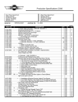


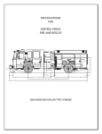
![MAPEAMENTO DE CONTROLE [CONTROLLER MAPPING]](http://vs1.manualzilla.com/store/data/006068957_1-5e2c8da72c516cb367b41ba39c141e7d-150x150.png)