1
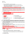
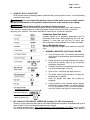
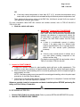
Page 1 of 21
Technical Service Bulletin
SUBJECT:
GENERAL PDI PROCEDURES
FOR 2012 MODELS
No:
TSB−11−00−005
DATE:
February, 2011
MODEL:
All 2012 Models
CIRCULATE TO:
[ ] GENERAL MANAGER
[ X ] PARTS MANAGER
[ X ] TECHNICIAN
[ X ] SERVICE ADVISOR
[ X ] SERVICE MANAGER
[ X ] WARRANTY PROCESSOR
[ X ] SALES MANAGER
PURPOSE
This bulletin contains general Pre−Delivery Inspection (PDI) procedures,
both technical and detail, for 2012 model year Mitsubishi vehicles. If
required, additional Technical Service Bulletins will be issued for
model−specific PDI procedures.
Diamond Care Delivery System (DCDS) folders, containing a Pre−Delivery
Inspection form, and a Sales Delivery form, should be used for all PDIs.
Note: Additional DCDS folders and forms may be ordered from Image
Printing Solutions by clicking the link on the main page of the MDL. If you
need help with ordering, contact them at 1−800−924−1350, or at
https://mmna.imgps.com, for assistance.
BULLETIN CONTENTS:
BACKGROUND INFORMATION . . . . . . . . . . . . . . . . . . . . . . . . . . . . . . . . . . . . . . .
Page 2
TECHNICAL INSPECTION: . . . . . . . . . . . . . . . . . . . . . . . . . . . . . . . . . . . . . . . . . . .
Page 2
Before You Start . . . . . . . . . . . . . . . . . . . . . . . . . . . . . . . . . . . . . . . . . . . . . . . . . . . . .
Page 2
A. . . . Vehicle Readiness . . . . . . . . . . . . . . . . . . . . . . . . . . . . . . . . . . . . . .
Page 3
B. . . . Interior − Functional Operation . . . . . . . . . . . . . . . . . . . . . . . . . . .
Page 3
C. . . . Walkaround Inspection . . . . . . . . . . . . . . . . . . . . . . . . . . . . . . . . . .
Page 6
D. . . . Underhood . . . . . . . . . . . . . . . . . . . . . . . . . . . . . . . . . . . . . . . . . . . . .
Page 9
E. . . . Under Vehicle . . . . . . . . . . . . . . . . . . . . . . . . . . . . . . . . . . . . . . . . . .
Page 10
F. . . . . Road Test . . . . . . . . . . . . . . . . . . . . . . . . . . . . . . . . . . . . . . . . . . . . . .
Page 10
DETAIL INSPECTION:
A. . . . Detailing Before PDI . . . . . . . . . . . . . . . . . . . . . . . . . . . . . . . . . . . .
Page 14
B. . . . Detailing After PDI . . . . . . . . . . . . . . . . . . . . . . . . . . . . . . . . . . . . . .
Page 15
FINAL DELIVERY PREPARATION . . . . . . . . . . . . . . . . . . . . . . . . . . . . . . . . . . . .
Page 18
COMPLETING THE PDI FORM . . . . . . . . . . . . . . . . . . . . . . . . . . . . . . . . . . . . . . . .
Page 19
PARTS INFORMATION . . . . . . . . . . . . . . . . . . . . . . . . . . . . . . . . . . . . . . . . . . . . . . .
Page 20
WARRANTY INFORMATION . . . . . . . . . . . . . . . . . . . . . . . . . . . . . . . . . . . . . . . . . .
Page 20
SAMPLE PRE−DELIVERY INSPECTION FORM . . . . . . . . . . . . . . . . . . . . . . . . .
Page 21
continued
Copyright 2011 Mitsubishi Motors North America, Inc.
(3740)
The information contained in this bulletin is subject to change. For the latest version of this document, go to the Mitsubishi Dealer Link,
MEDIC, or the Mitsubishi Service Information website (www.mitsubishitechinfo.com).
Page 2 of 21
TSB−11−00−005
BACKGROUND INFORMATION
The PDI processes described in this bulletin were developed to ensure a “fault−free” delivery. The
technical and detail procedures are divided into separate sections of this bulletin.
This bulletin contains general descriptions of most required Technical and Detail inspection checks
organized in a logical and time−efficient order. It is critical that all the steps are completed while
keeping the vehicle clean inside and out during the entire PDI process. Model specific PDI
bulletins and PDI Update bulletins supplement this bulletin when required.
NOTE: You can search for PDI bulletins in Group 00, General, either in the MEDIC TIR function, or on
the Mitsubishi Dealer Link, Service Technical Resources page.
The PDI process is important. Remember to:
D
Avoid pressure to rush through PDI.
D
Never skip steps on the PDI form.
Once you are familiar with these procedures, the PDI form acts as a guide to the process.
After reviewing this bulletin and any update and/or model−specific PDI bulletins, complete the 2012
PDI quiz from the Mitsubishi Academy at www.MitsubishiAcademy.com, if you haven’t already done
so.
NOTE: If any repairs are needed, ensure they are made before the customer takes delivery of the
vehicle. Any defects in materials and/or workmanship discovered during PDI should be
corrected and claimed under warranty. Adjustments and repairs are not part of the PDI flat
rate time.
PROCEDURE
Technical Inspection
The Detail Specialist should complete the DETAILING BEFORE PDI steps before handing the
vehicle off to the Technician for PDI Technical Inspection. Refer to the Detail Inspection section
of this bulletin for complete detailing information for both before and after Technical Inspection.
Use the PDI form and PDI bulletins as a guide. After completing each step, check−off that procedure
on the form. The sequence in which you perform the steps may vary depending on your dealership’s
procedures, facilities, and the vehicle itself. Be sure that all pertinent steps are checked on the form.
Be sure the PDI form is signed and dated, and a copy filed in the “vehicle packet” and service file at
your dealership.
IMPORTANT: DO NOT offer any vehicle for sale if it has an outstanding recall campaign. To
do so subjects the dealer to large fines. Check the Superscreen for possible
outstanding recalls.
BEFORE YOU START
Make sure the following information is recorded in the proper spaces on the PDI form.
D
Vehicle Identification Number (VIN)
D
Dealer stock number
D
Model
D
Ignition key code
D
Model Year
Page 3 of 21
TSB−11−00−005
A. VEHICLE READINESS
Before you start the inspection, retrieve the wheel covers, license plate bracket, radio antenna, and
any other shipped loose items from the trunk as applicable.
1. Engage (push down) the IOD connector. On most vehicles, the IOD connector is in the relay box
under the hood. Make sure that all doors and the trunk/hatch are closed. The ignition switch must
be off when engaging the IOD connector.
2. Start the engine to check cold start engine performance. The engine should start quickly using
all keys (or transmitters). It should idle smoothly and not have any hesitation or unusual noise when
accelerated.
Immobilizer
Separate ALL keys (or transmitters) and, confirm that ALL start the engine without stalling.
If the vehicle is equipped with the F.A.S.T. System or O.S.S., separate the transmitters and enter the
vehicle with only one transmitter at a time. Ensure the vehicle starts and does not stall, in both keyless
operation mode and using the emergency key (if equipped).
If the vehicle starts, then stalls, one or more keys may not have been registered, or there may be an
immobilizer system problem. Refer to the service manual for diagnostic procedures, and use MEDIC
and/or the Mitsubishi Dealer Link (MDL) site to search for TSBs relating to immobilizer system and
immobilizer key registration policies and procedures.
3. Install all shipped loose items (floor mats, antenna masts, wheel covers, wheel caps, front
license plate anchors, etc.)
4. Refer to MEDIC, or the Mitsubishi Dealer Link for any general or model−specific PDI TSBs. Be
sure all instructions on the TSBs are performed.
B. INTERIOR − FUNCTIONAL OPERATION
WARNING
Apply the parking brake and run the engine at idle while doing this inspection.
1. Check WINDOW, SEAT ADJUSTMENT, AND SEAT BELT operation.
WINDOWS: Check for proper window tracking, complete up and down travel, and proper sealing.
NOTE: For vehicles with power windows, check the lockout and AUTO−down & up (if equipped)
functions.
For power windows equipped with AUTO−up functions, check that the safety mechanism
functions normally. Refer to Group 42 − BODY, in the Service Manual for the proper checking
procedure.
SEAT ADJUSTMENT AND SEAT BELT/HEAD RESTRAINT OPERATION.
a. Make sure the seat backs for driver and front passenger adjust and lock in all positions.
b. Confirm the seat track adjusters operate and lock throughout their entire travel (front seats).
Leave the seat height adjuster (if equipped) in the lowest position for maximum head room.
c.
Check power seat operation (if equipped).
d. Check heated seat operation (if equipped).
e. Check HEAD RESTRAINTS
Ensure all head restraints are properly installed. Inspect the height adjustment for ease of
operation.
Page 4 of 21
TSB−11−00−005
f.
Check ALL SEAT BELTS for condition and operation.
− Inspect all seat belts and harnesses to ensure they connect and hold properly.
− Inspect operation of the height adjuster and condition of the seat belts, and anchors.
− Inspect for proper seat belt retraction.
− Check that safety labels regarding use of seat belts and air bags are in place.
2. Check SUNROOF, Panoramic Roof Panels, or CONVERTIBLE TOP operation (if equipped).
Ensure all controls work properly, including one−touch operation. Ensure the sunroof closes tightly,
and the tilt−up feature (if equipped) works. Open and close the sunroof a number of times to ensure
the timing of the functions works properly. The panoramic roof panel is equipped with one−touch
closing. Ensure that the sunroof or panoramic roof panel safety mechanism functions properly. Refer
to the applicable service manual and and perform the test for your specific vehicle.
For convertibles, ensure all windows lower automatically when opening and closing the top. Check
convertible top latch operation.
NOTE: If adjustments are required, refer to the appropriate service manual procedures and submit
a warranty claim for adjustment.
3. INTERIOR AND INSTRUMENT PANEL LIGHTS
Check that all interior lights operate:
D
Dome light(s)
D
Door courtesy lights
D
Map light(s)
D
Passenger airbag system lights
D
Vanity mirror light(s)
D
Cargo area light (if equipped)
D
Instrument panel illumination and
dimmer function
Glove box light (if equipped)
D
Panoramic roof ambient lighting (if equipped)
D
Accessory interior lighting (if equipped).
D
NOTE: Leave the instrument panel illumination on the brightest position. Position the dome light
switch so that the light is on when the door is open and off when the door is closed.
4. INSIDE AND OUTSIDE MIRRORS. Check and adjust exterior mirrors. Ensure the inside rear view
mirror holds its adjustment. Make sure the anti−glare, HomelinkR and backup camera functions
operate properly (if equipped).
5. HORN. Ensure all horn buttons are functional.
6. AUXILIARY ACCESSORY SOCKET(S) (if equipped). Check the auxiliary accessory sockets (if
equipped) for proper operation.
7. SET CLOCK AND ALL RADIO STATION PRESETS. Set the clock to the correct time. Set ALL “AM”,
“FM1”, & “FM2” preset buttons to a variety of strong local stations.
8. AUDIO SYSTEM OPERATION (INCLUDING SIRIUSt SATELLITE RADIO OPERATION if
equipped).
Check radio and speaker operation for:
D
Volume
D
Reception of AM & FM stations and SIRIUSt satellite radio (if equipped).
Ensure the satellite radio operates by tuning to channel 184, Emergency/News, to verify.
Satellite radio reception must be checked outside with a clear view of the Southern sky.
D
Tone (bass & treble)
D
Balance/Fader Controls
Page 5 of 21
TSB−11−00−005
D CD player, including CD−changer (if equipped)
D Rattling or vibrating speakers
D Check function of “AUX” and USB inputs
D Check FUSE Handsfree Link Systemt responds to voice commands
NOTE: Adjust the treble, bass, balance, and fader controls to their center position after radio
inspection.
9. MITSUBISHI MULTI−COMMUNICATION SYSTEM (MMCS) (if equipped)
a. Make sure the navigation screen displays your location when the NAVI button is pressed.
NOTE: The navigation system and Satellite radio may not operate properly if the vehicle is in
an enclosed area. This includes being surrounded by tall buildings. The default navigation location will be New York, NY. If this is not your location, move the vehicle to an
open area with a clear view of the Southern sky and recheck.
10. MULTI−INFORMATION DISPLAY (if equipped)
MULTI INFORMATION DISPLAY
Verify the screens are in English. If needed, the language
can be changed to French, Spanish, Japanese, German
or Italian.
Refer to the owners manual for more
information.
11. REAR−VIEW CAMERA SYSTEM (if equipped)
Turn the ignition switch to the ON position. Shift into reverse. Confirm the reverse image is clearly
displayed either the rear view mirror window (Eclipse models) or center display (all others).
12. HANDS−FREE TELEPHONE (if equipped)
NOTE: Some models place the hands−free control switches on the steering wheel if the vehicle is
pre−wired for handsfree operation. This does not mean the vehicle is hands−free equipped.
Refer to the Monroney label to determine if the vehicle is equipped for Hands−Free
telephone use.
SPEECH BUTTON
PHONE BUTTON
Outlander, Outlander Sport
and all Lancer models
Depress the SPEECH button. You will receive an audible
response advising that the system is connected and ready.
Say CANCEL to exit.
Page 6 of 21
TSB−11−00−005
<Front dome light assembly>
PHONE BUTTON
SPEECH BUTTON
PHONE BUTTON
Galant & Endeavor
SPEECH BUTTON
Eclipse & Eclipse Spyder
13. PASSENGER AIRBAG AND SEATBELT LIGHT FUNCTIONS.
Have someone sit in the front passenger seat and verify the passenger airbag light goes out. Verify
the passenger seat belt reminder light comes on when their seat belt is unfastened, and goes off when
their belt is fastened.
14. REAR WINDOW DEFOGGER and HEATED DOOR MIRROR (if equipped). Check with the engine
running. Turn the rear window defogger on, allow time for the defogger and mirror to warm up and
check them during the walk around inspection. Place your hand on the rear window defogger and
heated door mirror (if equipped) to ensure it is heating. Be sure to turn off the defogger after checking.
Turn the ignition switch off.
C. WALKAROUND INSPECTION
Before starting this section, ensure the engine is OFF, then turn the ignition switch to the “ON” position
and place the transmission selector in “R” (reverse) with the parking brake applied. DO NOT START
THE ENGINE.
1. Check EXTERIOR LIGHTS. Ensure ALL exterior lights operate properly. Check for chipped or
cracked lenses. On vehicles with AUTO−OFF headlights, turn on the headlights and turn the ignition
OFF. The headlights, side−marker lights, and taillights should turn off when the driver’s door is
opened. Be sure to turn ALL lights OFF after completing inspection. Return the transmission selector
to “P” (park).
Turn the ignition switch to the “OFF” position.
2. REMOTE KEYLESS ENTRY (RKE) or FREE−HAND ADVANCED SECURITY TRANSMITTER
(F.A.S.T.) SYSTEM, THEFT ALARM SYSTEM, ALL DOOR LOCKS, LATCHES, ONE−TOUCH
STARTING SYSTEM (O.S.S.) & IMMOBILIZER
RKE (if equipped)
Check the door and trunk (if equipped) locking and unlocking features.
Ensure the key is removed from the ignition. Close all doors and trunk.
D
Press the “lock” button once to lock all doors.
D
Pressing the “unlock” button once unlocks the driver’s door, and pressing it twice unlocks all doors
and the liftgate (if equipped).
D
For remotes with 3 buttons, the third button unlocks the trunk.
Press the “trunk” button twice to open the trunk.
D
Press the “Panic” button (if equipped) for 2 seconds to test the panic alarm. Press again to turn
off the panic alarm.
Page 7 of 21
TSB−11−00−005
NOTE: Factory−installed RKE systems have an “answerback” feature which can be customized for
various answerback functions, depending on the model and system installed. Ensure the
vehicle’s answerback feature is in the full−function answerback mode, where both the horn and
parking lamps signal when the doors are locked. Refer to the vehicle owner’s manual for
programming information.
F.A.S.T. (if equipped)
a. Install the knob on the end of the ignition lock cylinder.
b. Ensure door locks operate properly using the F.A.S.T. key.
c.
Ensure door locks operate properly using the lock/unlock buttons located on both front outer door
handles.
NOTE: The default mode for the F.A.S.T. Key system unlocks only the door where the button is
pressed.
O.S.S. (if equipped)
a. With the shift lever in P, depress the brake pedal and press the engine start/stop switch. The
vehicle should start.
b. Press the engine start/stop button again to turn the engine off.
c. With the shift lever in P, release the brake pedal and press the engine start/stop switch. The
engine does not start and the LED in the button lights amber (ACC mode).
Press the button again and the LED changes to green (ON mode).
Press the button again and the LED turns off.
d. Start the vehicle, depress the brake pedal and shift to D. Depress the engine start/stop switch
for 1 second. The engine should stop and the light in the switch turns amber.
Theft Alarm (if equipped)
Vehicles with standard security system
a. Lower the driver’s window. Remove the key from the ignition switch and exit the vehicle.
b. Close all doors and lock them using the transmitter. The security indicator on the instrument
panel will be lit for about 20 seconds and then blink at a slow rate when armed.
c. Reach through the open window, manually unlock the door, and then open it. The alarm horn
should sound and the headlights should flash.
TO DEACTIVATE THE ALARM:
Press the unlock button on the transmitter, or turn the ignition switch to the ACC or ON position
(transmitter must be present if equipped with F.A.S.T.).
d. Repeat steps a. through c. on the front passenger’s door and lock.
e. Repeat steps a. through c. using the trunk remote release and trunk lock.
f.
Repeat steps a. through c. on the hood release.
Vehicles with Premium Security Alarm System
Intrusion Inspection
a. Open the driver’s window and exit the vehicle.
b. Close all doors and lock lock them using the F.A.S.T. Key transmitter. The security indicator
on the instrument panel will be lit for about 20 seconds and then blink at a slow rate when
armed. Place the F.A.S.T. Key transmitter at least 5 feet from the vehicle.
Page 8 of 21
TSB−11−00−005
c. Reach through the open window. The alarm siren should sound.
d. DEACTIVATE THE ALARM:
Press the unlock button on the remote, or turn the ignition switch to the ACC or ON position
(transmitter must be present if equipped with F.A.S.T.).
Tilt Sensor Inspection
a. Repeat steps a & b above.
b. Jack up the front or rear of the vehicle. The alarm should sound.
d. Deactivate the alarm.
Door Locks & Latches
Close each door to check the latch and lock mechanisms. If adjustments are required, refer to the
appropriate service manual. Submit a warranty claim for any adjustment performed.
Child Safety Door Lock Operation
The rear door should not open from inside when the lever (located on the inside rear area of the door
near the latch mechanism) is in the lock position.
NOTE: Set the lever to the unlock or “FREE” position when you are finished checking its operation.
Fuel Filler Door
For vehicles with remote fuel door release, pull the release lever and make sure the fuel door opens.
Close the door and verify it latches properly.
For vehicles without remote release, make sure the fuel door opens and closes properly.
3. REMOTE ENGINE START (if equipped)
a. Remove the key from the ignition, close all doors, hood and the trunk(liftgate). For Endeavor, confirm the dome light is in the ROOM position.
b. Start the engine using the remote transmitter. Confirm the hazard lights flash once while the
engine is starting.
c.
Stop the engine using the remote transmitter.
d. Open one door and confirm the engine will not start with the remote transmitter.
4. TRUNK/HATCH/LIFTGATE, TRUNK LIGHT AND TRUNK/CARGO AREA TRIM APPEARANCE
Check for trunk/hatch/liftgate closing quality (make sure it closes easily) and fit. Fit should be uniform.
a. Check the operation of the remote trunk release (if equipped).
b. Verify trunk light (if equipped) comes on and all trim is installed properly.
5. Check REAR WINDOW WASHER FLUID (if equipped)
Top off the fluid if necessary.
6. Check TAILGATE LATCH operation
Make sure the tailgate closes with normal effort.
7. EMERGENCY INSIDE TRUNK RELEASE HANDLE (if equipped)
Check the operation of the emergency inside trunk release handle. Open the trunk lid and trip the
latch by pushing on the catch with the shaft of a screwdriver to simulate trunk closure. Remove the
screwdriver with the latch in the closed position, and verify emergency trunk release using the release
handle. For more information about the Emergency Inside Trunk Release, refer to the vehicle’s
owner’s manual.
Page 9 of 21
TSB−11−00−005
8. SPARE TIRE PRESSURE, WHEELS, JACK, TOOLS
Spare Tire Pressure
Some models require removal of the spare tire for tire pressure adjustment. Ensure the tire hold down
is secure after reinstalling the spare tire.
Jack & Tools
Check for jack and tools. On cars & Outlander Sport, the tools and jack are in the trunk. For other
vehicles:
D
Outlander − tools and jack are behind the access panel in the right hand quarter trim.
D
Endeavor − The jack is under the rear seat. Tools are under the cargo area floor with the spare
tire.
Insure that they are properly secured and will not rattle or come loose. Refer to the vehicle owner’s
manual or model−specific PDI related TSBs, if any, for more information concerning jack and tool
location.
D. UNDERHOOD
IMPORTANT: Use fender covers to protect the vehicle body.
1. Check BATTERY charge using your Midtronics Battery Tester. Check that the battery cable
terminals, and additional wires attached to the positive terminal are tight and that the battery is secure
in the tray.
Ensure the battery is fully charged (minimum 12.4 V). If charging is necessary, follow the service
manual procedures and recharge the battery. Remove the battery maintenance tag (if equipped) and
file it in the vehicle file with other PDI documentation.
2. Check ENGINE OIL
Check engine oil level. If oil is needed, check the appropriate Service Manual for correct grade of oil.
3. BRAKE, CLUTCH, AND POWER STEERING FLUID
Check the fluid levels on the scale on the plastic reservoir of both master cylinders (brake and clutch).
They should both be at the FULL mark. Fill if necessary.
NOTE: Use either DOT 3 or DOT 4 brake fluid (genuine Mitsubishi BRAKE FLUID, part number
MZ311987 or equivalent).
a. Check power steering fluid. It should be at the proper level on the dipstick or on the scale on the
plastic reservoir. Use genuine Mitsubishi Power Steering Fluid, part number 4039645.
4. Check COOLANT AND WINDSHIELD WASHER FLUID
Add fluid if necessary.
COOLANT −: For all Lancer−based models, Outlander and Outlander Sport, use only DiaQueen
Super Long Life Coolant (genuine Mitsubishi COOLANT, part number MZ320125). For all others use
a 50/50 mix of long life coolant (genuine Mitsubishi Long Life Coolant, part number MZ311986, or
equivalent).
WASHER FLUID − Use genuine Mitsubishi Washer Fluid (part number ACH3ZC1X07 or equivalent).
5. Check for FLUID LEAKS
6. CHECK HOOD LATCH and SAFETY CATCH
Make sure the hood release lever pulls evenly and that the hood cannot be lifted without releasing
the safety catch.
Page 10 of 21
TSB−11−00−005
7. Check for LOOSE ATTACHMENTS
Check for loose parts, wiring harness and cable clips and connections, incorrectly routed hoses and
harnesses, and insufficient clearance of components to moving engine parts.
8. EMISSION CONTROL EQUIPMENT
The Environment Protection Agency (EPA) requires this inspection.
Using the underhood label as a guide, verify all emission control equipment is installed.
NOTE: The EPA requires that dealers visually inspect the emission control devices prior to
delivery, or, as an alternative, inspect each vehicle for an illuminated malfunction indicator
light (MIL), and if the light is illuminated, diagnose and correct the malfunction.
E. UNDER VEHICLE
During PDI, every vehicle should be put on a lift for under vehicle inspection. Refer to the appropriate
service manual for vehicle lift points.
1. Remove the BRAKE ROTOR PROTECTION (covers) [if equipped].
2. Remove SPRING SPACERS and FRONT FASCIA PROTECTOR PLATE (if equipped)
3. Check for LOOSE ATTACHMENTS
Make sure all wiring harness clips, brake pipe clips, heat shield fasteners and any other attachments
are properly secured.
4. FLUID LEAKAGE
a. Check for leaks from any engine components, transmission, fuel lines, coolant hoses, power
steering lines, and A/C lines (if equipped). Check lines for twists, kinks, and proper routing.
5. ADJUST TIRE PRESSURE AND INSPECT TIRES FOR DAMAGE
Adjust tire pressure. For tire pressure specifications, refer to the Tire Pressure and Loading label on
the driver’s side B−pillar.
IMPORTANT: On some models, the factory over−inflates the tires by 50% to prevent flat spots
during shipment and storage. It is critical to adjust tire pressures to the proper specifications.
Check all tires for damage such as cuts, foreign objects in the tire, or any other imperfections.
Remove the tire pressure and tire balance decals from each tire if either or both decals are present.
NOTE: Low tire pressure on vehicles equipped with Tire Pressure Monitoring System (TPMS) will
cause the TPMS warning light to come on. Adjust tire pressure on TPMS equipped vehicles
to the specification shown on the Tire Pressure and Loading Label located below the driver’s
door striker. If a valve stem cap is missing, refer to Mitsubishi ASA CAPS and replace it only
with the part number quoted for the vehicle.
F. ROAD TEST
1. A/T / CVT / TC−SST SHIFT INTERLOCK
Make sure the shift lever can only be moved when the brake pedal is depressed and the ignition switch
is in the unlocked position. For vehicles with OSS, the engine must be running.
2. A/T / CVT / TC−SST STARTER INTERLOCK
Make sure the engine can be started ONLY when the shift selector is in PARK or NEUTRAL. For
vehicles equipped with O.S.S., the vehicle must only start if the brake pedal is depressed.
3. M/T CLUTCH − STARTER INTERLOCK
Make sure the engine will start only when the clutch pedal is depressed.
Page 11 of 21
TSB−11−00−005
4. CONDUCT A FULL ROAD TEST
Road test the vehicle to identify dynamic symptoms that you may need to correct. Use the following
instructions as a guide.
WARNING
Your route should be relatively free from other traffic so you can safely conduct
the test and concentrate on the operation and performance of the vehicle you are testing.
WARNING
Always follow all traffic laws and safe driving practices.
The PDI road test should be conducted under a variety of different operating and road conditions.
If the vehicle is equipped with air conditioning, place a thermometer in the center vent before
beginning your road test. This will be used later to check the air conditioner operation.
Preliminary Road Test Notes
Vehicles should be at operating temperature prior to
performing these tests. Before beginning the road test,
establish a route that you will use on every test.
Recommended road test duration is at least 15 minutes.
Record BEGINNING mileage
Record the beginning mileage of your road test on the PDI
form.
5. WARNING, INDICATOR LIGHTS AND GAUGES
a. Turn the ignition ON. The indicator and warning
lights shown in the illustration should illuminate (as
equipped).
or
b. Fasten the driver’s seat belt and start the engine.
Verify that all indicator lights go out, except the
passenger airbag light.
c.
or
Unfasten the driver’s seat belt and verify the driver
seat belt reminder light comes on.
d. Open a door. Verify door ajar light comes on.
e. The brake warning light should be lit when the
parking brake is applied.
f.
Verify all gauges and lights are working as
equipped.
g. Check operation of the seat belt warning buzzer
and the key reminder buzzer. For vehicles with the
F.A.S.T. Key system or OSS, move the transmitter
out of the vehicle and listen for a warning tone.
S Passenger Airbag Light
S TPMS (Tire Pressure
Monitoring System) Light
6. M/T: Check CLUTCH AND M/T OPERATION (including TC−SST shift functions)
Check for proper clutch operation and smooth shifter/transmission operation. Repeatedly shift up and
down at least 10 times at idle and at speeds under 40 mph.
For vehicles equipped with a Twin Clutch Sportronic Shift Transmission (TC−SST), slide the shifter
into the Manual Shift mode and manually shift through the gears. Also select Super Sport Mode (if
Page 12 of 21
TSB−11−00−005
equipped) by using the console mounted switch. Ensure the shift paddles shift gears properly and
manual shift mode cancels when a paddle is held for 2 seconds.
7. A/T: Check A/T / CVT / TC−SST OPERATION
a. From 25 mph, accelerate to full throttle. The transmission should kick down to 1st gear and then
shift to the higher gears. For CVT, the vehicle should accelerate smoothly.
b. Idle 20 seconds in “N” then shift to “D” then “R” holding each position for more than 3 seconds.
c.
Check for smooth shifting during normal driving. Then upshift through all gears with 20% and 30%
throttle and decrease to a stop. On vehicles with SportronicE shift, slide the shift lever into the
“Sport Mode” slot and upshift and downshift manually to verify proper operation.
d. Check paddle shifter operation (if equipped). Make sure the transaxle upshifts and downshifts
properly.
8. 4WD & AWD: Check TRANSFER CASE OPERATION (If equipped)
Check for proper engagement and disengagement in all 4WD modes. For detailed explanation of the
Transfer Case Operation, refer to the Owner’s Manual or in−vehicle decal.
9. Check ALL−WHEEL CONTROL (including S−AWC) FUNCTIONS (If equipped)
Ensure that the mode display changes when toggling the mode switch between TARMAC, GRAVEL
and SNOW.
10. Check ENGINE PERFORMANCE
WARNING
Always follow all traffic laws and safe driving practices.
Check engine performance under the following conditions. The throttle should be responsive and
without hesitation.
Part Throttle
With the vehicle at a constant speed (25−35 mph), engine performance should be smooth and without
hesitation.
Under Load
Accelerate to 3/4 throttle. The vehicle should accelerate smoothly, without laboring or hesitation.
At Cruise
With the vehicle at a constant speed (45−55 mph), engine performance should be smooth, without
hesitation or surging.
11. ELECTRONIC COMPASS (If equipped)
Refer to Group 52A in the service manual for electronic compass calibration instructions. Check the
compass variance (the difference between the earth’s magnetic north and true geographic north
poles). If compass variance is not adjusted properly, the compass can give false readings. The
electronic compass requires calibration when the battery cable is removed or IOD connector is
disconnected.
12. Check CRUISE CONTROL
Eclipse/Eclipse Spyder, Endeavor and Galant: The cruise control is operated by a stalk mounted
switch on the right side of the steering wheel hub. The main control switch is on the end of this stalk.
Lancer, Outlander Sport and Outlander models: The cruise control functions are mounted on the
steering wheel.
Control Functions
Main − Energizes and de−energizes the system and turns on the indicator light.
Set/Coast − Sets control speed. Also used to reduce the set speed.
Resume/Accel − Resumes previously set speed. Also used to increase the set speed.
System Operation Check
NOTE: The cruise control will not operate below 25 mph.
Page 13 of 21
TSB−11−00−005
a. Accelerate to 30 mph.
b. Turn on the MAIN switch. Make sure the CRUISE light illuminates.
c.
Activate the SET function to set the vehicle speed. The vehicle speed should hold at 30 mph.
d. Increase the vehicle speed slightly by activating the RESUME function momentarily.
e. Check each canceling function by depressing the brake, clutch (M/T only), and by activating the
CANCEL button.
f.
Resume the set speed by activating the ACC/RESUME button.
g. Turn the cruise control off by pressing the MAIN switch.
13. SQUEAKS, RATTLES, AND WIND NOISE
Check for any abnormal noise and vibration during your road test, including driveline, pedal, or
steering wheel vibration. On convertibles, have the top in the closed position during the road test.
Be sure to close all windows and sunroof and turn off the audio during this inspection.
14. STEERING OPERATION AND WHEEL ALIGNMENT
Make sure the steering wheel is centered when the vehicle is traveling straight ahead.
The vehicle should track straight on a level surface, without pulling or drifting. If a problem is identified,
correct it. Refer to the service manual for adjustment procedures.
15. BRAKE PERFORMANCE AND ABS OPERATION
a. Brake performance
The vehicle should brake smoothly and in a straight line. There should be no abnormal noise or
vibration during braking. Brake pedal feel should be firm, not soft or mushy.
b. ABS operation (if equipped)
WARNING
Always check that no vehicles are behind you when checking ABS.
In a safe location with no other vehicles or objects around, check the operation of the ABS system.
During hard braking, the vehicle should come to a controlled, straight stop. You will feel some
pedal pulsation and may hear normal operating sounds from the ABS system.
16. WINDSHIELD WIPER & WASHER OPERATION (front & rear)
WINDSHIELD WASHER AIM (front & rear)
c.
a. Check washer aim, both front & rear (if equipped).
b. Vehicles equipped with intelligent windshield washer − Pull the windshield washer lever for
approximately 0.5 seconds. Confirm the washer sprays between wiper blade sweeps, for a total
of 4 sprays. Refer to Group 51 Exterior of the Service Manual for details of intelligent washer
operation.
c.
Make any needed adjustments, referring to the service manual. Submit a warranty claim for
adjustments performed.
WINDSHIELD WIPER OPERATION (also rear if equipped)
a.
Verify correct wiper operation during all speeds. If streaking occurs, clean the wiper blades with
a cloth soaked in a mild detergent.
b. Make sure the wipers park properly.
17. HEATER AND A/C OPERATION (if equipped)
Check for proper operation of all modes, air intake selection, and temperature control. Check the fan
speed and check for any unusual fan noises.
Using a thermometer in the center air outlet, check for proper cooling when the air conditioner is
operating. Refer to the service manual for temperature specifications or test conditions for the
particular model. Make sure the air intake control is in the RECIRC position.
Page 14 of 21
TSB−11−00−005
18. HOT ENGINE IDLE SPEED WITH A/C ON AND OFF
With the engine at operating temperature, check the idle quality with the air conditioning ON and OFF.
When finished, leave the air intake door in the FRESH position.
19. Check PARKING BRAKE
Park the vehicle on a slight incline and leave the transmission in NEUTRAL. With your foot off the
service brake, the parking brake should be able to hold the vehicle.
NOTE: Count the number of “click” notches it takes to engage the parking brake. If it is more than 8,
adjust the parking brake according to service manual procedures.
20. Check ATF
With the parking brake applied and the engine running, check automatic transmission fluid level as
per the applicable service manual. Add or extract fluid if necessary to ensure level is at the HOT marks
on the dipstick.
21. Record the ENDING mileage
Record the ending mileage of your road test onto the PDI form.
22. *** IMPORTANT ***
RECALLS − Check the Warranty Superscreen for any open recalls. Make sure any open recall
is performed BEFORE the vehicle is offered for sale.
FINAL STEPS FOR TECHNICAL INSPECTION
D
Sign and date the Technician’s Signature area on the PDI form. Leave the form with the vehicle
for the Detail Specialist for after−PDI detailing.
D
Sign and install the PDI Quality Assurance Pledge decal.
ÍÍÍÍÍÍÍÍÍÍÍÍÍÍÍÍÍÍÍÍÍÍÍÍÍÍÍÍÍÍÍÍÍ
Detail Inspection
A. DETAILING BEFORE PDI
BEFORE YOU START
NOTE: Always keep your hands and uniform clean when performing a PDI.
To protect the interior of the vehicle, be sure to remove sharp objects from your body and clothing
before starting the detailing procedures.
Make sure the following information is recorded in the spaces provided on the PDI form:
D
Vehicle Identification Number (VIN)
D
Dealer name and code
D
Model
D
Dealer stock #
D
Model Year
1. RAP−FILM REMOVAL (if applicable)
Before a technician can perform the Technical portion of a PDI, the protective film (RAP−film) must
be removed from the exterior body surfaces.
NOTE: For easiest removal, the temperature of the RAP−FILM should be between 32_F (0_C) and 122_F
(50_C).
a. Remove the RAP−film from all body surfaces:
D
If the temperature of the vehicle body is higher than 122_F (50_C), the film softens, allowing
more residue to remain on the body surface. For easier removal, decrease the temperature
of the vehicle body surface to less than 104_F (40_C) with cool water and/or store the vehicle
inside, out of the sun.
Page 15 of 21
TSB−11−00−005
OR
D
If the body surface temperature is lower than 32_F (0_C), increase the temperature using
warm water or put the vehicle inside a heated facility until the body surface temperature rises.
Then, starting at the corners, pull up on the RAP−film, fold it back, and pull it off at an angle of
180 degrees to minimize glue residue.
For more information about RAP−film removal and residue removal, refer to TSB−97−00−006 &
TSB−00−00−002.
b. Wash the vehicle with water.
2. IMPORTANT: Remove RAP−FILM RESIDUE
A line of adhesive residue can form at the edge of the
RAP−FILM. As the film shrinks due to exposure to the
elements, the adhesive is exposed and collects dirt
and other debris. Use either of the following methods
to remove the RAP−FILM residue from the body
surface.
D
If there is a considerable amount of residue,
remove it by wiping down the affected body
surface area with Biosol 100 or isopropyl alcohol,
diluted 50% with mineral spirits (petroleum
benzene).
OR
D
If there is only a small amount of residue, use a
very mild (white) polishing compound on the
affected surface area.
For details on removing RAP−film and residue, refer to
TSB−97−00−006 & TSB−00−00−002.
3. Inspect for PAINT DAMAGE
a. Inspect the vehicle’s surfaces for paint swelling (paint will have a milky appearance). This
condition occurs when moisture is trapped between the RAP−film and the body panel surface.
b. Most occurrences of paint swelling can be corrected by parking the vehicle in bright sun light for
approximately one hour.
NOTE: If the above repairs are not successful for correcting paint swelling, refer to the paint repair
procedures in the Body Repair Manual.
c.
At this time it is recommended that the Technical Inspection be completed. Continue the Detail
portion after the Technical Inspection is finished.
Whenever possible, install all accessories and dealer installed options BEFORE performing Detailing and Final Delivery Preparation.
B. DETAILING AFTER PDI
1. Remove RAP−FILM (if not already done). Refer to previous DETAILING BEFORE PDI section.
2. Wash ALL EXTERIOR BODY PANELS.
Page 16 of 21
TSB−11−00−005
a. Always make sure the windows and sunroof (if equipped) are fully closed. For convertibles, make
sure the top is closed and latched Otherwise, water may enter, causing damage.
b. Wash all body panels with water, not in direct sunlight.
c.
Start washing from the roof, working downward, using a sponge and water.
d. After washing, wipe water from body surfaces using a chamois or soft cloth.
NOTE: When using a high−pressure washer avoid directing high−pressure spray at weatherstrips.
3. Check for WATER LEAKS immediately after washing.
During storage, when the vehicle has been exposed to rain with the RAP−film removed, or while
washing the vehicle, note any water leaks that may require repair.
Remember that the source of the water leak is not always where the leak appears. To accurately locate
and then repair the leak, a thorough understanding of the circumstances under which it was identified
must be made known to the person doing the repairs.
NOTE: In some cases, it may take 4 minutes or longer to produce any evidence of leaks.
4. Wash & inspect ALL WHEELS; THOROUGHLY REMOVE ALL GLUE RESIDUE; Apply TIRE
DRESSING.
a. Install any missing valve stem caps with the correct cap. Your parts department can provide the
correct part for the vehicle.
b. Wash the wheels with mild detergent and rinse with water. See TSB−09−31−005 for information.
c.
After washing, wipe water from wheels using a chamois or soft cloth.
d. Inspect wheels and tires for nicks, scratches, and other damage.
e. Clean off any residue or foreign material.
f.
Apply tire dressing to each tire.
g. Wipe dry with a clean cloth.
5. Check DOOR & TRUNK OPENING CLEANLINESS and UNDERHOOD CLEANLINESS.
Wipe off any dirt with a damp cloth.
UNDERHOOD:
a. Remove any debris such as leaves, etc. from the engine compartment.
b. Wipe up any fluid spills and note any evidence of leakage on the repair order.
c.
Wipe down the engine compartment components with a damp cloth.
6. Inspect PAINT and ALL BODY PANELS FOR DAMAGE, ALIGNMENT, and FIT & FINISH.
a. Check for scratches and dents. Inspect the body panels from different angles.
b. Check the alignment of all body panels for uniform gaps and flushness. All body panels should
be flush with their adjoining panels and all gaps should be uniform.
c.
Inspect painted surfaces for uniform color. Inspect from different angles.
d. Inspect painted areas for damage. Note any discrepancies on the repair order.
e. Inspect painted areas for environmental fallout such as acid rain and rail dust. Remove any fallout
by following MMNA−approved techniques.
NOTE: If any paint damage is noted, refer to TSB−92−51−001 and training video #44.
7. Inspect ALL GLASS FOR DAMAGE and CLEANLINESS, INSIDE & OUTSIDE.
Use a suitable glass cleaner and wipe dry with a soft lint−free cloth.
Page 17 of 21
TSB−11−00−005
a. Use an approved glass polish to remove minor scratches and imperfections.
b. If there is a problem with any glass, follow your dealer’s procedures to correct it.
8. Inspect ALL MOLDING, TRIM, AND CHROME PARTS & REMOVE PROTECTIVE TAPE.
a. Inspect the moldings, trim, and chrome parts for looseness, proper alignment, and cleanliness.
b. Clean off any residue.
c.
Note needed repairs as they are corrected. Remember, repairs are not part of your PDI time.
Follow warranty policy and procedures.
9. Inspect ALL WEATHERSTRIPPING AND RUBBER MOLDINGS.
a. Inspect all weatherstrips and rubber moldings for damage and make sure they are mounted
correctly.
b. Clean off any residue.
10. Clean the INTERIOR and check ALL INTERIOR PANELS & TRIM FOR PROPER FIT.
a. Wipe plastic interior components with a soft damp cloth.
b. Remove minor stains and soil using a mild detergent, then wipe dry with a clean, soft cloth.
c.
Check alignment of all interior panels and trim for uniform gaps and flushness. All interior panels
and trim should be flush with their adjoining panels, and all gaps should be uniform.
NOTE: DO NOT remove the protective seat covers at this time.
11. Check for STAINS, DIRT, SCUFFS, OR TEARS.
If stains or soil are found on interior trim, do the following:
a. Clean with a mild soap solution or reliable vinyl cleaner.
b. Apply a small amount of solution with a clean cloth or sponge and work into a lather, then wipe
with a damp cloth.
c.
When the lather has been removed, wipe again with a soft, clean cloth.
NOTE: Damage and/or stains which cannot be removed using the above method should be noted on the
repair order and corrected prior to customer delivery.
12. Check that DOOR EDGE GUARDS ARE IN PLACE.
Check that door edge guards are in the proper position and securely fastened.
13. Install the CARGO NET (if applicable)
Install the cargo net according to the instructions in the package or vehicle owner’s manual.
14. Place PAPER MATS IN ALL FLOOR AREAS.
Install paper floor mats on the driver’s side and all passenger areas of the vehicle.
15. Check HEADLINER & SUN VISOR CLEANLINESS.
If stains or soil are found on the headliner or sun visors:
a. Clean with a mild soap solution or reliable vinyl cleaner.
b. Apply a small amount of solution with a clean cloth or sponge and work into a lather, then wipe
with a damp cloth.
c.
When the lather has been removed, wipe again with a soft, clean cloth. After cleaning the
headliner, use a small brush to raise the nap on the headliner material.
ÍÍÍÍÍÍÍÍÍÍÍÍÍÍÍÍÍÍÍÍÍÍÍÍÍÍÍÍÍÍÍÍÍÍ
ÍÍÍÍÍÍÍÍÍÍÍÍÍÍÍÍÍÍÍÍÍÍÍÍÍÍÍÍÍÍÍÍÍÍ
16. Disengage (pull up) the IOD (Ignition Off Draw) FUSE (Vehicles to be Stored).
Page 18 of 21
TSB−11−00−005
Final Delivery Preparation
1. Engage (push down) the IOD (Ignition Off Draw) connector (Vehicles from Storage).
2. Wash ALL EXTERIOR BODY PANELS.
a. Always make sure the windows, sunroof (if equipped) and convertible top are fully closed and
latched to prevent water entry.
b. Wash all body panels with water, not in direct sunlight.
c.
Start washing from the roof, working downward, using a sponge and water.
d. After washing, wipe water from body surfaces using a chamois or 100% cotton terry towel.
NOTE: When using a high−pressure washer avoid directing high−pressure spray at weatherstrips.
3. Wash ALL WHEELS & APPLY TIRE DRESSING.
a. Install any missing valve stem caps with the correct cap. Your parts department can provide the
correct part for the vehicle.
b. Wash the wheels with mild detergent and rinse with water. See TSB−09−31−005 for information.
c.
After washing, wipe water from wheels using a chamois or 100% cotton terry towel.
d. Apply tire dressing to each tire.
e. Wipe dry with a clean cloth.
4. Check DOOR & TRUNK OPENING, and UNDERHOOD for CLEANLINESS.
Wipe off any dirt with a damp cloth.
UNDERHOOD:
a. Remove any debris such as leaves, etc. from the engine compartment.
b. Wipe up any fluid spills. Note any evidence of leakage on the repair order.
c.
Wipe engine compartment components with a clean damp cloth.
5. Inspect ALL BODY PANELS FOR DAMAGE AND ALIGNMENT.
Check for scratches and dents. Inspect the body panels from different angles.
6. Inspect ALL PAINTED SURFACES FOR DAMAGE AND FINISH QUALITY.
a. Inspect painted surfaces for uniform color. Inspect from different angles.
b. Inspect painted areas for damage.
c.
Inspect painted areas for environmental fallout, such as acid rain and rail dust. Remove any fallout
by following MMNA−approved techniques.
NOTE: If any paint damage is noted, refer to TSB−92−51−001 and training video #44.
7. Clean ALL GLASS (INSIDE & OUT). Inspect ALL GLASS FOR DAMAGE
a. Use a suitable glass cleaner and wipe dry with a soft lint−free cloth.
b. Clean any dirt off the wiper blades.
c.
Use an approved glass polish to remove minor scratches and imperfections.
8. Inspect ALL MOLDING, TRIM, AND CHROME PARTS.
a. Inspect the moldings, trim, and chrome parts for looseness, proper alignment, and cleanliness.
b. Clean off any residue.
Page 19 of 21
TSB−11−00−005
9. Remove SEAT & TRIM PROTECTORS.
a. Carefully remove the protectors from all seats.
b. Carefully remove all trim protectors.
10. Check HEADLINER & SUN VISOR CLEANLINESS.
If stains or soil are found on the headliner or sun visors:
a. Clean with a mild soap solution or reliable vinyl cleaner.
b. Apply a small amount of solution with a clean cloth or sponge, then wipe with a damp cloth.
c.
When the lather has been removed, wipe again with a soft, clean cloth.
11. Check for STAINS, DIRT, SCUFFS, OR TEARS.
If the interior trim is scuffed, stained or soiled, clean as
described in Detailing After PDI, step 11.
NOTE: Damage and/or stains which cannot be
removed using the described method should be
noted on the repair order.
12. Remove PAPER MATS, FOOT PEDAL PLASTIC
PROTECTORS, VACUUM ALL FLOOR CARPETS,
INSTALL AND ANCHOR ALL FLOOR MATS.
a. Remove all paper floor mats and plastic pedal
protectors (if equipped).
b. Vacuum all floor carpets.
c.
Install and anchor floor mats for all seating
positions. Do not install more than one floor mat
in the driver’s position. Refer to TSB−11−00−001
for additional information.
13. Confirm VEHICLE INSTALLED ACCESSORY WEIGHT
Refer to TSB−09−00−001 for details. Complete and attach a “Load Carrying Capacity Reduced” label
if applicable.
14. Check tire pressures and adjust if necessary. Reinstall valve stem caps.
NOTE: Tire pressures are shown on the Tire Pressure and Loading label on the driver’s side B−pillar.
15. Set all AM and FM radio presets to customer−preferred stations.
COMPLETING THE PDI FORM
When finished, make sure both the PDI Technician and the Detail Specialist have signed the PDI form.
Leave the yellow (2nd copy) in the vehicle’s glove box. Keep the original copy with the vehicle’s service
file. A sample of the PDI form appears at the end of this bulletin.
Additional Diamond Care Delivery booklets and PDI forms can be ordered from Image Printing
Solutions https://mmna.imgps.com) by clicking the link on the main page of the MDL. If you need
help with ordering, contact them at 1−800−924−1350, or at https://mmna.imgps.com, for
assistance.
Page 20 of 21
TSB−11−00−005
PARTS INFORMATION
The table below lists Genuine Mitsubishi fluids which may be required during PDI:
Description
Part Number
Long Life Coolant
MZ311986
DiaQueen Super LLC Premium coolant
MZ320125
Brake Fluid
MZ311987
Washer Fluid (concentrate)
ACH3ZC1X07
Automatic Transmission Fluid Dia Queen J1 (for CVT)
S0001610
Automatic Transmission Fluid Dia Queen J3 (Outlander w/6 speed auto. trans.)
4031610
Automatic Transmission Fluid ATF SP−III
ACH1ZC1X05
Power Steering Fluid
4039645
NOTE: Fluid additions are included as part of the PDI reimbursement labor times.
WARRANTY INFORMATION
The PDI procedures described in this bulletin, as well as any fluids required during the PDI process, are
reimbursed under a single PDI labor time allowance dependent on the model. Current PDI labor time
allowances are provided in the Warranty Central menu option on the MDL (Mitsubishi Dealer Link).
Current applicable PDI labor time allowances are also automatically entered for you when the PDI claim
is keyed into the MDL claim entry system.
NOTE: Any additional repairs and/or adjustments caused by an issue with materials and/or workmanship
that are not part of these published PDI procedures should be claimed on a separate warranty
claim using the applicable published LOTS labor time for the repair(s) or the “zero−zero” actual
time procedure for non−published repairs and/or adjustments.
Page 21 of 21
TSB−11−00−005