1
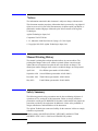
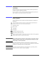
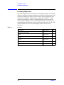
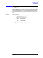
Agilent 42942A Terminal Adapter
Operation and Service Manual
Forth Edition
Agilent Part No. 42942-90020
May 2003
Printed in: Japan
Notices
The information contained in this document is subject to change without notice.
This document contains proprietary information that is protected by copyright.All
rights are reserved. No part of this document may be photocopied, reproduced, or
translated to another language without the prior written consent of the Agilent
Technologies.
Agilent Technologies Japan, Ltd.
Component Test PGU-Kobe
1-3-2, Murotani, Nishi-Ku, Kobe-shi, Hyogo, 651-2241 Japan
© Copyright 1999,2003 Agilent Technologies Japan, Ltd.
Manual Printing History
The manual’s printing date and part number indicate its current edition. The
printing date changes when a new edition is printed. (Minor corrections and
updates that are incorporated at reprint do not cause the date to change.) The
manual part number changes when extensive technical changes are incorporated.
April 1999
First Edition (part number: 42942-90000)
September 1999 Second Edition (part number: 42942-90010)
December 1999
Third Edition (part number: 42942-90010)
May 2003
Forth Edition (part number: 42942-90020)
Safety Summary
The following general safety precautions must be observed during all phases of
operation, service, and repair of this instrument. Failure to comply with these
precautions or with specific WARNINGS elsewhere in this manual may impair the
protection provided by the equipment. In addition it violates safety standards of
design, manufacture, and intended use of the instrument.
The Agilent Technologies assumes no liability for the customer’s failure to comply
with these requirements.
NOTE
42942A comply with INSTALLATION CATEGORY 1and POLLUTION
DEGREE 2 in IEC 1010-1. 42942A are INDOOR USE product.
2
•
DO NOT Operate In An Explosive Atmosphere
Do not operate the instrument in the presence of flammable gasses or fumes.
Operation of any electrical instrument in such an environment constitutes a
definite safety hazard.
•
Keep Away From Live Circuits
Operating personnel must not remove instrument covers. Component
replacement and internal adjustments must be made by qualified maintenance
personnel. Do not replace components with the power cable connected. Under
certain conditions, dangerous voltages may exist even with the power cable
removed. To avoid injuries, always disconnect power and discharge circuits
before touching them.
•
DO NOT Service Or Adjust Alone
Do not attempt internal service or adjustment unless another person, capable of
rendering first aid and resuscitation, is present.
•
DO NOT Substitute Parts Or Modify Instrument
Because of the danger of introducing additional hazards, do not install
substitute parts or perform unauthorized modifications to the instrument.
Return the instrument to a Agilent Technologies Sales and Service Office for
service and repair to ensure that safety features are maintained.
•
Dangerous Procedure Warnings
Warnings, such as the example below, precede potentially dangerous
procedures throughout this manual. Instructions contained in the warnings must
be followed.
WARNING
Dangerous voltages, capable of causing death, are presenting this instrument.
Use extreme caution when handling, testing, and adjusting this instrument.
Certification
Agilent Technologies certifies that this product met its published specifications at
the time of shipment from the factory. Agilent Technologies further certifies that
its calibration measurements are traceable to the United States National Institute of
Standards and Technology, to the extent allowed by the Institution’s calibration
facility, or to the calibration facilities of other International Standards Organization
members.
3
Warranty
This Agilent Technologies instrument product is warranted against defects in
material and workmanship for a period corresponding to the individual warranty
periods of its component products. Instruments are warranted for a period of one
year. Fixtures and adapters are warranted for a period of 90 days. During the
warranty period, Agilent Technologies will, at its option, either repair or replace
products that prove to be defective.
For warranty service or repair, this product must be returned to a service facility
designated by Agilent Technologies. Buyer shall prepay shipping charges to
Agilent Technologies and Agilent Technologies shall pay shipping charges to
return the product to Buyer. However, Buyer shall pay all shipping charges, duties,
and taxes for products returned to Agilent Technologies from another country.
Agilent Technologies warrants that its software and firmware designated by
Agilent Technologies for use with an instrument will execute its programming
instruction when property installed on that instrument. Agilent Technologies does
not warrant that the operation of the instrument, or software, or firmware will be
uninterrupted or error free.
Limitation Of Warranty
The foregoing warranty shall not apply to defects resulting from improper or
inadequate maintenance by Buyer, Buyer-supplied software or interfacing,
unauthorized modification or misuse, operation outside the environmental
specifications for the product, or improper site preparation or maintenance.
IMPORTANT
No other warranty is expressed or implied. Agilent Technologies specifically
disclaims the implied warranties of merchantability and fitness for a particular
purpose.
Exclusive Remedies
The remedies provided herein are buyer’s sole and exclusive remedies. Agilent
Technologies shall not be liable for any direct, indirect, special, incidental, or
consequential damages, whether based on contract, tort, or any other legal theory.
4
Assistance
Product maintenance agreements and other customer assistance agreements are
available for Agilent Technologies products.
For any assistance, contact your nearest Agilent Technologies Sales and Service
Office. Addresses are provided at the back of this manual.
Safety Symbol
General definitions of safety symbols used on the instrument or in manuals are
listed below.
Instruction Manual symbol: the product is marked with this symbol when it is
necessary for the user to refer to the instrument manual.
Alternating current.
Direct current.
On (Supply).
Off (Supply).
In position of push-button switch.
Out position of push-button switch.
Frame (or chassis) terminal. A connection to the frame (chassis) of the equipment
which normally include all exposed metal structure.
WARNING
This warning sign denotes a hazard. It calls attention to a procedure, practice,
condition or the like, which, if not correctly performed or adhered to, could
result in injury or death to personnel.
CAUTION
This Caution sign denotes a hazard. It calls attention to a procedure, practice,
condition or the like, which, if not correctly performed or adhered to, could result
in damage to or destruction of part or all of the product.
NOTE
Note denotes important information. It calls attention to a procedure, practice,
condition or the like, which is essential to highlight.
5
6
Contents
1. Installation Guide
Incoming Inspection . . . . . . . . . . . . . . . . . . . . . . . . . . . . . . . . . . . . . . . . . . . . . . . . . . . . . . . . . . . . . . . . . . . 10
Connecting the 42942A . . . . . . . . . . . . . . . . . . . . . . . . . . . . . . . . . . . . . . . . . . . . . . . . . . . . . . . . . . . . . . . . 11
Cleaning . . . . . . . . . . . . . . . . . . . . . . . . . . . . . . . . . . . . . . . . . . . . . . . . . . . . . . . . . . . . . . . . . . . . . . . . . . . . 12
Serial Number . . . . . . . . . . . . . . . . . . . . . . . . . . . . . . . . . . . . . . . . . . . . . . . . . . . . . . . . . . . . . . . . . . . . . . . . 13
2. Overview
Product Overview . . . . . . . . . . . . . . . . . . . . . . . . . . . . . . . . . . . . . . . . . . . . . . . . . . . . . . . . . . . . . . . . . . . . . 16
Functions. . . . . . . . . . . . . . . . . . . . . . . . . . . . . . . . . . . . . . . . . . . . . . . . . . . . . . . . . . . . . . . . . . . . . . . . . . . . 17
3. Operation
4294A Setup . . . . . . . . . . . . . . . . . . . . . . . . . . . . . . . . . . . . . . . . . . . . . . . . . . . . . . . . . . . . . . . . . . . . . . . . . 20
Adapter Setup . . . . . . . . . . . . . . . . . . . . . . . . . . . . . . . . . . . . . . . . . . . . . . . . . . . . . . . . . . . . . . . . . . . . . . 20
Connecting Test Fixture . . . . . . . . . . . . . . . . . . . . . . . . . . . . . . . . . . . . . . . . . . . . . . . . . . . . . . . . . . . . . . . . 24
Fixture Compensation. . . . . . . . . . . . . . . . . . . . . . . . . . . . . . . . . . . . . . . . . . . . . . . . . . . . . . . . . . . . . . . . . . 25
Performing Open Compensation. . . . . . . . . . . . . . . . . . . . . . . . . . . . . . . . . . . . . . . . . . . . . . . . . . . . . . . . 25
Performing Short Compensation. . . . . . . . . . . . . . . . . . . . . . . . . . . . . . . . . . . . . . . . . . . . . . . . . . . . . . . . 25
Performing Load Compensation . . . . . . . . . . . . . . . . . . . . . . . . . . . . . . . . . . . . . . . . . . . . . . . . . . . . . . . . 25
Fixture Extension . . . . . . . . . . . . . . . . . . . . . . . . . . . . . . . . . . . . . . . . . . . . . . . . . . . . . . . . . . . . . . . . . . . . . 27
4.
Specifications
Specifications . . . . . . . . . . . . . . . . . . . . . . . . . . . . . . . . . . . . . . . . . . . . . . . . . . . . . . . . . . . . . . . . . . . . . . . . 30
5. Service
Maintenance . . . . . . . . . . . . . . . . . . . . . . . . . . . . . . . . . . . . . . . . . . . . . . . . . . . . . . . . . . . . . . . . . . . . . . . . . 32
7
Contents
8
1
Installation Guide
9
Installation Guide
Incoming Inspection
Incoming Inspection
Inspect the shipping container for damage. If the shipping container or cushioning
material is damaged, it should be kept until the contents of the shipment have been
checked for completeness and the 42942A has been checked mechanically and
electrically. The shipment should contain everything listed in Table 1-1. If the
contents are incomplete or if there is mechanical damage or defect, notify the
nearest Agilent Technologies office. If the shipping container is damaged or the
cushioning material shows signs of unusual stress, notify the carrier as well as the
Agilent Technologies office. Keep the shipping materials for the carrier’s
inspection.
Table 1-1
Contents
Description
Part Number
Qty.
42942A Terminal Adapter
-
1
OPENa
04191-85302
1
SHORTa
04191-85300
1
LOADa
04291-60043
1
Operation and Service Manual
42942-90010
1
Carrying Case
42942-60011
1
a. Furnished with Option 700.
10
Chapter 1
Installation Guide
Connecting the 42942A
Connecting the 42942A
Follow the steps below to connect the 42942A to the 4294A.
Step 1. Join the 42942A terminal adapter to the test connectors on the front panel of the
4294A by gently matching the four BNC connectors and fastening screws of the
adapter with the test connectors and accessory mounting holes of the instrument
until they come into complete contact.
Step 2. Turn the adapter’s two fastening screws clockwise at the same time until the
fixture is firmly secured to the instrument.
Figure 1-1
Connecting 42942A to 4294A
Chapter 1
11
Installation Guide
Cleaning
Cleaning
Even a tiny amount of dirt on the 7-mm connector of the OUTPUT port would
greatly degrade the accuracy of your measurement. Use a lint-free cloth to clean
the connector if it gets dirty.
12
Chapter 1
Installation Guide
Serial Number
Serial Number
Agilent Technologies uses a two-part, ten-character serial number that is stamped
on the serial number plate (Figure 1-2) attached to the bottom of the adapter. The
first four letters and one digit are the serial prefix and the last five digits are the
suffix.
Figure 1-2
Serial Number Plate
Chapter 1
13
Installation Guide
Serial Number
14
Chapter 1
2
Overview
15
Overview
Product Overview
Product Overview
The 42942A is an adapter equipped with a 7-mm coaxial connector that connects a test
fixture furnished with the same type of connector to the 4294A Precision Impedance
Analyzer.
Figure 2-1
Product Overview
16
Chapter 2
Overview
Functions
Functions
Figure 2-2 and Figure 2-3 show the names of the 42942A’s parts and contents of the option
700, respectively.
Figure 2-2
42942A Parts
Table 2-1
42942A Function
No.
NAME
FUNCTION
1
OUTPUT Port
Contact for the test fixture furnished with a 7-mm
coaxial connector.
2
Mounting Post
Guide and support post for fixture connection.
3
Adapter Fastening Screws
Secures the fixture to the 4294A.
Chapter 2
17
Overview
Functions
Figure 2-3
Option 700 7-mm Open/Short/Load set
Table 2-2
Contents of the option 700
No.
NAME
FUNCTION
4
OPEN
An open device (OPEN, 0S) used for the adapter
setup.
5
SHORT
A short device (SHORT, 0 W) used for the adapter
setup.
6
LOAD
A load device (50 W) used for the adapter setup.
18
Chapter 2
3
Operation
This chapter describes the proper methods for adapter setup of the 42942A,
connecting a fixture, and fixture compensation.
19
Operation
4294A Setup
4294A Setup
Before beginning measurements, you should perform the adapter setup. The
following procedure shows adapter setup for the 42942A. Also refer to the
operation manual of the 4294A for more information on adapter setup.
CAUTION
When handling the 42942A, care must be taken not to give it any mechanical
shock, which may damage the adapter. Never give any mechanical shock to the
upper face with the 7-mm connector’s mouth. Also, do not place the 42942A with
the upper face down on a hard surface.
NOTE
If the ambient temperature deviates by more than 5°C from the temperature in
which the adapter setup was done, it is recommended that you again perform the
adapter setup in the ambient temperature.
Adapter Setup
Connect the 42942A to the 4294A and perform the adapter setup as described
below.
1. Power on the 4294A. Allow 30 minutes or longer for warm-up.
2. Press [Cal] key to bring up the Calibration Menu.
3. Press ADAPTER [ ] key to bring up the Adapter Setup Menu. [ ] should
indicate current settings.
4. Select 7mm 42942A. When selected, the softkey label will be underlined.
5. Press SETUP key to bring up the Adapter Setup Menu.
6. Turn the 7-mm OUTPUT port connector clockwise until the connector sleeve is
fully exposed.
NOTE
Even a tiny amount of dirt on the 7-mm OUTPUT port connector would greatly
degrade the accuracy of your measurement. Keep the connector clean and never
touch the mating plane surfaces. Use a lint-free cloth to clean the connector if it
gets dirty.
CAUTION
The 7-mm OUTPUT port connector is sensitive to damage and thus requires
careful handling. When not used, protect the mating plane surfaces with end caps.
20
Chapter 3
Operation
4294A Setup
Figure 3-1
Extending Connector Sleeve
7. Connect the OPEN standard to the 7-mm OUTPUT port connector.
CAUTION
Figure 3-2
Never store the OPEN standard loosely in a box or drawer because this may result
in damage to the mating plane surfaces. Do not drop the OPEN standard or give it
any strong mechanical shock.
Connecting OPEN Standard
8. Press PHASE COMP [-] key to start the phase compensation data measurement.
When the phase compensation data measurement is completed, the softkey label
Chapter 3
21
Operation
4294A Setup
changes to PHASE COMP [DONE].
9. Press OPEN [-] key to start the open data measurement. When the open data
measurement is completed, the softkey label changes to OPEN [DONE].
10. Remove the OPEN standard and connect the SHORT standard to the 7-mm
OUTPUT port connector.
CAUTION
Figure 3-3
Never store the SHORT standard loosely in a box or drawer because this may
result in damage to the mating plane surfaces. Do not drop the SHORT standard or
give it any strong mechanical shock.
Connecting SHORT Standard
11. Press SHORT [-] key to start the short data measurement.When the short data
measurement is completed, the softkey label changes to SHORT [DONE].
12. Remove the SHORT standard from the 7-mm OUTPUT port connector of the
42942A. Then connect the LOAD standard to the 7-mm port.
CAUTION
Never store the LOAD standard loosely in a box or drawer because this may result
in damage to the mating plane surfaces. Do not drop the LOAD standard or give it
any strong mechanical shock. When not used, protect the mating plane surfaces
with end caps.
22
Chapter 3
Operation
4294A Setup
Figure 3-4
Connecting LOAD Standard
13. Press LOAD [-] key to start the load data measurement. When the load data
measurement is completed, the softkey label changes to LOAD [DONE].
14. Press done key.
Chapter 3
23
Operation
Connecting Test Fixture
Connecting Test Fixture
After the adapter setup, you can connect the test fixture to the terminal adapter.
Refer to the manual that came with the fixture for the connection procedure. The
connection procedure shown below is common to most fixtures.
1. Turn the 7-mm OUTPUT port connector on the terminal adapter
counterclockwise until the connector sleeve is fully retracted.
2. Join the test fixture to the terminal adapter by keying the mounting posts and
the OUTPUT port of the adapter.
3. Turn the 7-mm OUTPUT port connector on the terminal adapter
counterclockwise to secure it to the connector on the lower side of the test
fixture.
Figure 3-5
Connecting Test Fixture
24
Chapter 3
Operation
Fixture Compensation
Fixture Compensation
To compensate for any residual impedance and admittance existing in the test
fixture, perform fixture compensation. The fixture compensation requires
measurements with the 42942A for open and short compensation data. Generally,
there is no need to perform load compensation. For more information on fixture
compensation, refer to the 4294A Operation Manual.
NOTE
Electrical length is noted on the test fixture and its furnished manual. There is no
need to set the electrical length in the 4294A when using the 42942A. Only
OPEN/SHORT compensation will eliminate the error.
Performing Open Compensation
The following procedure is for measurement of the open compensation data.
1. Be sure that the fixture is open, without any connection between the
measurement terminals.
2. Press [Cal] key to bring up the Calibration Menu.
3. Press FIXTURE COMPEN key to bring up the Fixture Compensation Menu.
4. Press OPEN key to start the OPEN compensation data measurement. When the OPEN
compensation data measurement is completed, the softkey label OPEN on OFF (if
it is off) changes to OPEN ON off.
Performing Short Compensation
The following procedure is for measurement of the short compensation data.
1. Put the terminal of the test fixture into the SHORT state. For more information on
shorting methods, refer to the manual that came with the fixture.
2. Press SHORT key to start the SHORT compensation data measurement.When the
SHORT compensation data measurement is completed, the softkey label SHORT on
OFF (if it is off) changes to SHORT ON off.
Performing Load Compensation
Generally, there is no need to perform load compensation. If you have any standard
device or you need to keep consistency in measured data, perform the load
compensation by using the device. When you perform load compensation, set the
load value of the device to the instrument.
The following procedure is for the measurement of the load compensation data.
1. Connect the load device to the terminal of the test fixture. For more information
on connecting methods, refer to the manual that came with the fixture.
2. Press LOAD key to start the LOAD compensation data measurement.When the LOAD
Chapter 3
25
Operation
Fixture Compensation
compensation data measurement is completed, the softkey label LOAD on OFF (if
it is off) changes to LOAD ON off.
26
Chapter 3
Operation
Fixture Extension
Fixture Extension
The 42942A is designed to connect directly to the 4294A. Thus, the measurement
point on the four-terminal pair cannot be extended by using four extension cables
as shown in Figure 3-6 (A). The 42942A must be directly connected to the 4294A
as shown in Figure 3-6 (B). For fixture extension, use a coaxial cable connected to
the 7-mm OUTPUT port on the 42942A. Note that the 42942A’s specified
accuracy will no longer be assured with this extension. For calibration of the
extended fixture, refer to the 4294A operation manual.
Figure 3-6
Fixture Extension
Chapter 3
27
Operation
Fixture Extension
28
Chapter 3
4
Specifications
This chapter provides specifications of the 42942A test fixture.
29
Specifications
Specifications
Specifications
Applicable Instruments
4294A Precision Impedance Analyzer
Frequency
40 Hz to 110 MHz
Maximum Voltage
± 42 V peak max. (AC+DC)
Operating
Environment
temp.
0°C to +40°C
humidity
15% to 95%RH ( @ wet bulb temp. < 40°C)
Non-operating
temp.
-40°C to +70°C
Environment
humidity
£ 90 % RH ( @ wet bulb temp. <65°C)
Dimensions
300 (W) ´ 100 (H) ´ 280 (D) mm (Includes carrying
case)
Weight
2300g ( 42942A body 800g)
Safety Standards
EN61010-1:1993 +A2:1995
IEC61010-1:1990 +A1:1992 +A2:1995
CSA C22.2 No.1010.1:1992
INSTALLATION CATEGORY I
POLLUTION DEGREE 2
INDOOR USE
For more information on impedance measurement accuracy at the 3.5-mm port and
additional error factor, refer to the 4294A Operation Manual.
30
Chapter 4
5
Service
This chapter provides information on servicing and proper maintenance.
31
Service
Maintenance
Maintenance
An exploded view of the 42942A for parts identification is shown in Figure 5-1
and Figure 5-2. Do not disassemble any further than shown. Maintenance consists
principally of cleaning contacts and replacing worn or damaged parts. Take special
care when cleaning contacts.
To order parts, use the Agilent Technologies part numbers listed in Table 5-1 and
Table 5-2. If a faulty part is located in an assembly that cannot be disassembled,
order the next higher assembly or return the fixture to the nearest Agilent
Technologies Sales/Service Office for repair or replacement.
Figure 5-1
Replaceable Parts (part 1 of 2)
32
Chapter 5
Service
Maintenance
Table 5-1
Replaceable Parts (part 1 of 2)
Reference
Designator
Part No.
Qty.
Description
1
42942-24007
2
SHAFT
2
0510-0083
2
RTNR-R
3
1460-2615
2
SPRING
4
42941-40002
2
BUSHING
5
1253-0476
4
ADPT BNC-SMB
6
3050-0067
4
WSHR-FL MTLC
7
3050-0789
4
WSHR-FL NM
8
2950-0054
2
TNUT-HEX-DBL-CHAM
9
2190-0054
2
WSHR-LK INTL
10
42942-00602
1
COVER BOTTOM
11
16047-40002
4
INSULATOR
12
0515-0914
2
SCR-MACH M3X0.5
13
42941-25002
2
SLEEVE
14
42942-25006
1
BNC-GUIDE
15
42941-24003
2
GUIDE
16
42942-00603
1
COVER
17
0515-0914
2
SCR-MACH M3X0.5
18
0515-1551
2
SCR M3-L 10 P-H
Chapter 5
33
Service
Maintenance
Figure 5-2
Replaceable Parts (part 2 of 2)
34
Chapter 5
Service
Maintenance
Table 5-2
Replaceable Parts (part 2 of 2)
Reference
Designator
Part No.
Qty.
Description
1
42942-00601
1
COVER TOP
2
1250-0907
1
CONTACT CENTER
3
1250-1466
1
CONN-RF 7mm
4
0515-1550
4
SCR M3-L 8 P-H
5
0515-0914
6
SCR-MACH M3X0.5
6
1400-0719
4
CABLE TIE
7
0515-1719
2
SCR M4X10
3050-0893
2
WSHR-FL
0515-1718
1
SCR M4X12
3050-0893
1
WSHR-FL
42942-60001
1
7mm ASSY (exclude 4.6.7.8)
8
9
Chapter 5
35
Service
Maintenance
36
Chapter 5
REGIONAL SALES AND SUPPORT OFFICES
For more information about Agilent Technologies test and measurement products, applications, services, and
for a current sales office listing, visit our web site: http://www.agilent.com/find/tmdir. You can also contact one
of the following centers and ask for a test and measurement sales representative.
11/29/99
United States:
Agilent Technologies
Test and Measurement Call Center
P.O.Box 4026
Englewood, CO 80155-4026
(tel) 1 800 452 4844
Canada:
Agilent Technologies Canada Inc.
5150 Spectrum Way
Mississauga, Ontario
L4W 5G1
(tel) 1 877 894 4414
Europe:
Agilent Technologies
Test & Measurement
European Marketing Organization
P.O.Box 999
1180 AZ Amstelveen
The Netherlands
(tel) (31 20) 547 9999
Japan:
Agilent Technologies Japan Ltd.
Call Center
9-1, Takakura-Cho, Hachioji-Shi,
Tokyo 192-8510, Japan
(tel) (81) 426 56 7832
(fax) (81) 426 56 7840
Latin America:
Agilent Technologies
Latin American Region Headquarters
5200 Blue Lagoon Drive, Suite #950
Miami, Florida 33126
U.S.A.
(tel) (305) 267 4245
(fax) (305) 267 4286
Australia/New Zealand:
Agilent Technologies Australia Pty Ltd
347 Burwood Highway
Forest Hill, Victoria 3131
(tel) 1-800 629 485 (Australia)
(fax) (61 3) 9272 0749
(tel) 0 800 738 378 (New Zealand)
(fax) (64 4) 802 6881
Asia Pacific:
Agilent Technologies
24/F, Cityplaza One, 1111 King’s Road,
Taikoo Shing, Hong Kong
(tel) (852)-3197-7777
(fax) (852)-2506-9284