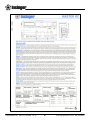
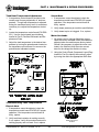
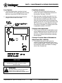
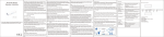
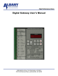
1
TECHNICAL MANUAL
FLIGHT-TYPE DISHMACHINES
Master/Clipper RC
Includes Installation, Operation, and Maintenance Instructions
Insinger Machine Company
6245 State Road
Philadelphia, PA 19135-2996
800.344.4802
Fax 215.624.6966
www.insingermachine.com
Thank you for purchasing this quality
Insinger product.
On the space provided below please record the
model, serial number and start-up date of this unit:
Model:__________________________________
Serial Number:___________________________
Start-Up Date:____________________________
When referring to this equipment please have this
information available.
Each piece of equipment at Insinger is carefully
tested before shipment for proper operation. If the
need for service should arise please contact your
local Authorized Insinger Service Company.
A Service Network Listing is provided on our web
site, www.insingermachine.com or call Insinger at
800-344-4802 for your local authorized servicer.
For proper activation of the Insinger Limited
Warranty a SureFire™ Start-Up & Check-Out
Service should be completed on your machine.
Refer to the Introduction section in this manual for
an explanation of Insinger SureFire™ Start-Up &
Check-Out Program.
Please read the Insinger Limited Warantyt and all
installation and operation instructions carefully
before attempting to install or operate your new
Insinger product.
To register your machine for warranty by phone, fax
or the internet or for answers to question
concerning installation, operation, or service contact
our Technical Services Department:
TECHNICAL SERVICE CONTACTS
Toll-Free
800-344-4802
Fax
215-624-6966
E-mail
[email protected]
Web
www.insingermachine.com
Clipper/Master RC DOC FLT-CLPMST 1.0 04
TABLE OF CONTENTS
Part 1
Technical Information
• Introduction
• Cut-sheets & Installation Drawings
• Warranties
Part 2
Installation Instructions
• Installation and Start-Up Procedures
Part 3
Operating & Cleaning Instructions
• Operating Procedures
• Cleaning Procedures
Part 4
Maintenance & Repair Procedures
• Maintenance & Repair Procedures
• Basic Service Guide
3-13
14-15
16-17
18-20
Part 5
Electrical Schematics & Replacement Parts 21-31
• Machine Wiring Diagrams
• Control Panel Layout & Component Drawings
Part 6
Spare Parts List
• Recommended Spare Parts List
Part 7
Replacement Parts
• Overall Assembly Drawings for:
Clipper RC
Master RC
• Conveyor Overload Assembly
• Pump Assemblies
• Fill & Final Rinse Piping Assemblies
• Photo-eye Assembly
• Level Float & Detergent Probe Locations
• Curtain Locations
• Electrical Heaters
• Steam Heating
• Lighting Parts
• Conveyor Assemblies
32
33-73
www.insingermachine.com 800-344-4802
Clipper/Master RC DOC FLT-CLPMST 1.0 04
1
www.insingermachine.com 800-344-4802
Clipper/Master RC DOC FLT-CLPMST 1.0 04
2
www.insingermachine.com 800-344-4802
Clipper/Master RC DOC FLT-CLPMST 1.0 04
3
www.insingermachine.com 800-344-4802
Clipper/Master RC DOC FLT-CLPMST 1.0 04
4
www.insingermachine.com 800-344-4802
Clipper/Master RC DOC FLT-CLPMST 1.0 04
5
www.insingermachine.com 800-344-4802
Clipper/Master RC DOC FLT-CLPMST 1.0 04
6
www.insingermachine.com 800-344-4802
Clipper/Master RC DOC FLT-CLPMST 1.0 04
7
www.insingermachine.com 800-344-4802
Clipper/Master RC DOC FLT-CLPMST 1.0 04
8
www.insingermachine.com 800-344-4802
PART 1 TECHNICAL INFORMATION
MASTER/CLIPPER FLIGHT MACHINES
INTRODUCTION
Purpose
The purpose of this technical manual is to provide
installation, operation, cleaning and maintenance
directions.
NSF 3-2003 requirements for detergent
and chemical sanitizer dispensers.
This machine must be operated with an automatic
detergent dispenser and, if applicable, an automatic
chemical sanitizer feeder, including a visual means
to verify that detergents and sanitizers are delivered
or a visual or audible alarm to signal if detergents
and sanitizers are not available for delivery to the
respective washing and sanitizing systems. Please
see instructions for electrical and plumbing connections located in this manual and in the feeder equipment manual.
A section is provided for replacement parts.
Scope
This manual contains all pertinent information to assist in the proper installation, operation, cleaning,
maintenance, and parts ordering for Insinger Flight
machines including the Clipper and Master.
The installation instructions are intended for
qualified equipment installers. The operation and
cleaning instructions are intended for the daily
users of the equipment. The maintenance and
parts sections are intended for qualified service
and/or maintenance technicians. Replacement parts
may be ordered directly from our factory or from
your local Insinger Authorized Service Agency.
You can speak to the Insinger Technical Services
Department, 800/344-4802, or e-mail us at
[email protected]. When calling for
warranty information or replacement parts please
provide the model and serial number of your
Insinger Equipment. These important numbers
should be noted in this manual on the spaces
provided on the opening page.
Definitions
Throughout this guide you will find the following
terms: WARNING, CAUTION, & NOTE.
WARNING indicates potential physical danger.
CAUTION indicates potential equipment damage.
NOTE indicates helpful operating hints or tips.
You will visually be able to identify each as
shown below:
!
Surefire™ Start-up & Check-out Program
Insinger is proud to offer our exclusive Surefire™
Start-up & Check-out Program to our commercial
customers. This service is included in the purchase
price of your new Insinger dishwasher. We will
provide an authorized factory service technician for
the initial start-up of your new Insinger dishwasher
to ensure it is running at optimum levels from the
very first pass. Please call the factory or your local
Insinger Sales Representative to schedule this
service.
WARNING:
Indicates potential physical danger.
þ
NOTE:
Indicates helpful operating hints or tips.
CAUTION:
Indicates potential equipment damage.
Clipper/Master RC DOC FLT-CLPMST 1.0 04
9
www.insingermachine.com 800-344-4802
PART 1 TECHNICAL INFORMATION
INSINGER MACHINE COMPANY LIMITED WARRANTY
Insinger Machine Company, Inc. (Insinger) hereby
warrants to the original retail purchaser of this
Insinger Machine Company, Inc. product, that if it is
assembled and operated in accordance with the
printed instructions accompanying it, then for a
period of either 15 months from the date of shipment
from Insinger or 1 year (12 months) from the date of
installation, that said Insinger product shall be free
from defects in material and workmanship. Whichever one of the two aforestated limited warranty
time periods is the longest shall be the applicable
limited warranty coverage time period.
the instruction booklet (operating instructions) or
for improper operation or failure to follow normal
operating instructions (as set out in the instruction
booklet). Insinger is not responsible nor liable for
any conditions of erosion or corrosion caused by
corrosive detergents, acids, lye or other chemicals
used in the washing and or cleaning process.
Service must be done by either Insinger Appointed
Service Agencies or agencies receiving prior
authorization from Insinger.
All warranty work must be done during normal
working hours, unless purchaser receives prior
authorization from Insinger.
Insinger may require reasonable proof of your date
of purchase; therefore, you should retain your copy
of invoice or shipping document.
There are no other express warrants except as set
forth herein and any applicable implied warranties
of merchantability and fitness are limited in
duration to the period of coverage of this express
written limited warranty. This limited warranty
supersedes all other express warranties, implied
warranties of merchant-ability and fitness or limited
warranties as of this date, January 1, 1998. Some
states do not allow limitation on how long an
implied warranty lasts so this limitation may not
apply to you.
This limited warranty shall be limited to the repair
or replacement of parts which prove defective under
normal use and service and which on examination
shall indicate, to Insinger’s satisfaction, they are
defective. Any part that is claimed to be defective
and covered by this limited warranty must be
returned to Insinger, this may be done through an
Authorized Service Agency. Furnish serial number
of machine with shipment and send to:
Insinger Machine Company
6245 State Road
Philadelphia, PA 19135-2996
If Insinger’s inspection confirms the defect and the
claim, Insinger will repair or replace such part without charge and return it to you freight or postage
prepaid.
Insinger is not liable for any special, indirect
or consequential damages. Some states do not
allow the exclusion or limitation of incidental or
consequential damages, so this limitation nor
exclusion may not apply to you.
This limited warranty does not cover any failure or
accident, abuse, misuse, alteration, misapplication,
improper installation, fire, flood, acts of God or
improper maintenance or service, or failure to perform normal and routine maintenance as set out in
Insinger does not authorize any person or company
to assume for it any other obligation or liability in
connection with the sale, installation, use, removal,
return or replacement of its equipment: and no such
representations are binding on Insinger.
Clipper/Master RC DOC FLT-CLPMST 1.0 04
10
www.insingermachine.com 800-344-4802
PART 1 TECHNICAL INFORMATION
INSINGER MACHINE COMPANY LIMITED WARRANTY
COMMERCIAL MARINE USE
Insinger Machine Company, Inc. (Insinger) hereby
warrants to the original retail purchaser of this Insinger
Machine Company, Inc. product, that if it is assembled
and operated in accordance with the printed instructions
accompanying it (installation manual), then for a period
of 18 months from the date of installation on board the
vessel, that said Insinger product shall be free from
defects in material and workmanship.
customer at a reduced rate of $40.00 per hour. If sailing
with a vessel is required, then an eight hour per day
minimum will apply.
This limited warranty does not cover accident, abuse,
misuse, alteration, misapplication, improper installation,
fire, flood, or improper maintenance or service, or
failure to perform normal and routine maintenance as
set out in the instruction booklet (operating instructions)
or for improper operation or failure to follow normal
operating instructions (as set out in the instruction
booklet).
Insinger may require reasonable proof of your date of
equipment install, therefore, you should retain your copy
of invoice or shipping document.
This limited warranty shall be limited to the replacement
of parts which prove defective under normal use and
service and which on examination shall indicate, to
Insinger's satisfaction, they are defective. Any part that
is claimed to be defective and covered by this limited
warranty must be returned to Insinger. Furnish serial
number of machine with shipment and send to:
Insinger is not responsible nor liable for any conditions
of erosion or corrosion caused by corrosive detergents,
acids, lye or other chemicals used in the washing, caring
and or cleaning process.
Warranty service must be done by either Insinger
Appointed Service Agencies or agencies, customers
galley engineers receiving prior authorization from
Insinger.
Insinger Machine Company, Inc.
6245 State Road
Philadelphia, PA 19135-2996
If Insinger's inspection confirms the defect and the claim,
Insinger will repair or replace such part without charge
and return it to you freight or postage prepaid. If part
damages are not covered, Insinger will contact Customer
and advise.
There are no other express warrants except as set
forth herein and any applicable implied warranties of
merchantability and fitness are limited in duration to
the period of coverage of this express written limited
warranty. This limited warranty supersedes all other
express warranties, implied warranties of merchantability and fitness or limited warranties as the above date.
If a factory trained authorized technician is required
to repair or replace defective parts or material during
the 18 month warranty period, the cruise line will be
responsible for the payment of travel expense and a
minimum of four hours labor. Labor will be billed to the
Insinger does not authorize any person or company
locally or overseas to assume for it any other obligation
or liability in connection with the sale, installation, use,
removal, return or replacement of its equipment; and no
such representations are binding on Insinger.
Clipper/Master RC DOC FLT-CLPMST 1.0 04
11
www.insingermachine.com 800-344-4802
PART 2 INSTALLATION INSTRUCTIONS
INSTALLATION INSTRUCTIONS
Mechanical Requirements
Connect 140ºF and 180ºF water supply to the tank
and final rinse feeds respectively as tagged on the
machines and noted on the installation drawing.
Placement
Carefully uncrate machine.
Bolt the three sections together.
þ
If machine is provided with steam heat connect the
steam lines and steam condensate lines as tagged
and noted on installation drawings.
NOTE:
Connect the drain lines.
Use a silicone caulking between the sections in
addition to the gasketing material provided.
This will minimize the possibility of leaks.
þ
NOTE:
Drain lines must be as specified on installation
drawings. Drain line should be properly vented
and should have fall of not less than ¼” to the
foot of proper flow. Some area plumbing codes
require drains to flow into an open gap with an
opening twice the diameter of the pipe. Check
with your local plumbing codes for the type of
drain connection required.
Electrical Connections
Connect electrical lines sized for the correct voltage,
current and phase of the machine. These should
agree with machine requirements indicated on the
nameplate and labels in control panel.
On machines not provided with a single-point connection there is an electrical connection required for
the, 1. Pumps and control circuit, 2. Wash tank
heaters (electric heat only) and, 3. Rinse tank heaters (electric only).
þ
NOTE:
All lines should be flushed prior to use to
remove debris.
Machines provided with a single-point connection
require one electrical connection in the control panel
for all functions excluding the booster.
þ
NOTE:
þ
NOTE:
Do not reduce the size of lines as specified in
installation drawings. All lines are sized to
facilitate necessary flows, pressures, etc.
In each case connections must be made to a
circuit breaker or fused disconnect as provided
by the end-user and required by local codes.
A wiring diagram is supplied inside the control
panel. Please return diagram when finished.
Adjust the compression spring located on the conveyor overload shutoff mechanism. This can be
found on the unload end of the machine under the
mechanism guard. There is sticker marked with the
factory test setting of the spring. Adjust to this point
then run the conveyor full of ware. If the machine
does not shut down the adjustment is set. If it does
shut down adjust the spring tighter until the machine
runs continuously.
þ
NOTE:
As with any 3 phase system, an electrician
should check all motors for proper phasing,
i.e., Pump motors must be running in direction
indicated by arrow on housing.
Electrical termination points are also required between each of the sections in the termination box
located on the frame in the rear of the machine near
where the sections meet.
Clipper/Master RC DOC FLT-CLPMST 1.0 04
12
www.insingermachine.com 800-344-4802
PART 2 INSTALLATION INSTRUCTIONS
HVAC
Ventilation system should be sized to provide
adequate ventilation per machine specs. Refer to
spec sheet.
Stainless steel, watertight ducting should be
connected to the vent cowls on each end of the
machine or an overhead venting system should be
installed.
Chemicals
Upon completed installation of the dishwasher
contact a local detergent/chemical supplier for the
correct chemicals for your area.
Electrical connection points for the detergent
dispenser and rinse injector are located inside the
control panel. Refer to the wiring diagram for this
machine for the proper connection points. The
detergent density probe should be located in a
convenient place in the wash tank.
Clipper/Master RC DOC FLT-CLPMST 1.0 04
13
www.insingermachine.com 800-344-4802
PART 3 OPERATION & CLEANING INSTRUCTIONS
þ
NOTE:
Insinger dishwashers are user-friendly, making them
the easiest dishwashers on the market to operate
and maintain.
An emergency stop bar is located at the end of
the conveyor belt to shut the belt down. This
will minimize ware breakage if the machine is
not unloaded in time.
By following the operation procedure and general
cleaning procedures your Insinger dishwasher will
give you years of trouble free service.
10. For machines provided with the Conveyor Overload Shutoff Mechanism a light labeled “Check
Conveyor Belt” is provided on the control panel.
When this light illuminates the machine will automatically shut down. Check the conveyor belt for
jamming or ware caught in the belt.
OPERATION INSTRUCTIONS
1. Ensure drain overflow tube is in place. Close all
tank drain valves. One drain is provided for
each tank of the dish machine.
2. Check for proper installation and cleanliness of
all internal, removable components such as
suction strainers, scrap screens, and spray
manifolds.
þ
NOTE:
Should the light illuminate and the machine
shut-down after an initial check for jams, DO
NOT continue running the machine. Immediately
contact a maintenance person or qualified service technician. Refer to the Conveyor Overload
Shutoff Mechanism Adjustment section in the
Maintenance Section of the manual.
3. Ensure all water, and steam lines are open.
Ensure electrical circuits are on.
4. Close machine doors.
þ
NOTE:
11. The system is now ready for operation. All ware
should be properly scrapped.
An interlock is provided to shut the machine
down if the doors are open, therefore the
machine will not run if doors are opened.
Machines provided with the Prison Package
do not have this feature.
12. Place dirty ware on the conveyor belt. The ware
will pass through the various machine cycles.
The final rinse is automatically started when
ware passes the photo-eye located at the
entrance of the machine.
5. Move the 2 position selector switch to the “ON”
position.
6. The machine will automatically begin to fill.
þ
NOTE:
7. When the tanks are full the tank heat will operate
automatically.
The photo-eye located at the entrance of the
machine should be cleaned daily of lime buildup for proper operation of the energy saver
feature and the final rinse.
þ
NOTE:
To ensure proper operation of the auto tank fill
feature and the tank heaters the two (2) level
probes located in each tank MUST be cleaned
daily.
þ
8. Depress the Green button on the control panel
to operate the pumps.
Move the Power toggle switch to the “OFF”
position before draining the machine.
13. Refer to the cleaning procedures for proper
clean-up of the dish machine.
9. Located at the load and unload end of the machine is a start/stop station for operating the
conveyor system. Depress the green button to
start the conveyor.
Clipper/Master RC DOC FLT-CLPMST 1.0 04
NOTE:
14. Report any unusual occurrences to qualified
service personnel.
14
www.insingermachine.com 800-344-4802
PART 3 OPERATION & CLEANING INSTRUCTIONS
CLEANING PROCEDURES
The following cleaning procedures should be done
daily, at the end of the shift.
Daily
1. Remove all internal removable parts including
spray manifolds, scrap screens, drain overflow
tubes, suction strainers and curtains.
2. Remove the end caps from the spray manifolds
and clean with the brush provided. Flush the
manifolds.
3. Flush scrap screens.
4.
Clean drain overflow tube.
þ
NOTE:
V-cup seal on the drain overflow tube may
become gummed not allowing a proper seal
of the overflow tube. This will cause the drain to
leak water. Remove any build-up on the V-cup
seal. When the seal becomes worn, replace.
!
5. Clean suction strainers of build-up.
WARNING:
Level floats must be cleaned daily. Build-up of
grease and scum will cause faulty operation of
tank fill and heating system.
7. Clean curtains. When curtains are beyond
cleaning or torn they should be replaced.
þ
NOTE:
Improper cleaning of suction strainer will cause
the pumps to cavitate. This will cause poor
washing results.
8. Final rinse nozzles should be cleaned of matter
clogging the jet spray.
9. Clean the photo-eye lenses with a damp, soft
cloth.
6. Clean tank level floats (2 per tank) with ScotchBrite or equivalent.
Clipper/Master RC DOC FLT-CLPMST 1.0 04
10. Doors should be left open to allow drying of
interior surfaces.
15
www.insingermachine.com 800-344-4802
PART 4 MAINTENANCE & REPAIR PROCEDURES
Line Strainer Disassembly
1. Shut off water or steam supply.
The following is a basic guide for the repair and
replacement of common dishwasher parts. Refer to
the Basic Service Guide for troubleshooting tips.
2. Remove large hex nut on bottom of strainer body.
MAINTENANCE REQUIREMENTS
3. Remove strainer screen. Inspect and clean or
replace as necessary.
Daily
1. Refer to the operation and cleaning instructions
provided in this manual for daily cleaning procedures.
4. Reassemble in reverse of disassembly. Water
flow must be same direction as arrow on line
strainer body. Use new gaskets to insure a tight
seal.
Weekly
1. The entire machine should be wiped down using
an industrial grade stainless steel cleaner.
Pump Disassembly
1. Before disassembling pump ensure there are no
obstructions in the pump intake. Remove and
clean the suction strainer (inside tank). See dwg.
SK-4702 and SK-4702
2. Under the supervision of your detergent supplier
the machine interior must be properly de-limed.
þ
NOTE:
2. IT IS NOT NECESSARY TO REMOVE THE
PUMP HOUSING FROM THE MACHINE TO
DISASSEMBLE THE PUMP.
The water quality in some areas requires deliming to be done more frequently. Contact your
detergent supplier for recommended de-liming
frequency.
3. Remove the pump motor and impeller adaptor by
removing the 4 hex bolts attaching them to the
pump housing.
Quarterly
1. Remove and clean the strainer screens on water
and steam lines. If the screens cannot be
cleaned, replace.
2. Inspect condition of solenoid valve seats and
diaphragms. Replace where necessary.
3. Inspect drain O-Rings for leakage. Replace
where necessary.
4. Adjust conveyor chain tension using adjustment
bolts located on exit end of machine.
4. Repair or replace the pump parts as required.
Reassemble in reverse of disassembly.
Immersion Heater Replacement
1. The immersion heater MUST be completely submerged at all times. If this is not the case contact
a qualified service technician. The heated surface
should never be in contact with sludge. See dwg.
SK-4703
MAINTENANCE PROCEDURES
2. Remove the housing covering the wiring terminations. Disconnect the immersion heater wires.
Solenoid Valve Disassembly
1. Disconnect power supply to machine. Turn off
water supply.
3. Remove the immersion heater by loosening and
removing the large hex nut.
4. Install in reverse of removal.
2. Remove cap on top of coil. Remove coil.
3. Remove 4 hex bolts and lift bonnet from valve
body. Note positioning of spring and plunger.
þ
4. Remove main piston.
5. Inspect for dirt, wear or lime build-up. Clean or
replace as required.
NOTE:
Use plumbers putty as gasketing around the
immersion heater to insure no leaks.
6. Reassemble in reverse of disassembly.
Clipper/Master RC DOC FLT-CLPMST 1.0 04
16
www.insingermachine.com 800-344-4802
PART 4 MAINTENANCE & REPAIR PROCEDURES
Tank Heat Temperature Adjustment
1. A temperature control board is provided in the
control panel for easy adjustment of tank temperature. Though tank temperature is adjusted
during the machines factory test it is sometimes
necessary to re-adjust the temperature at startup.
Steam Heat
1. If temperature cannot be adjusted, check the
temperature control board P/N DE9-251 proper
operation. If the temperature control board is
faulty, replace.
2. Locate the temperature control board (P/N DE9251). Use the control panel layout drawing
located in Part 5, Electrical Schematic and Replacement Parts.
3. Verify steam trap is not clogged. If so, replace.
2. Verify steam pressure per machine specifications.
Motor Overloads
1. All motors used on Insinger Machines are provided with motor overloads. Motor overloads are
adjusted when the machines are factory tested.
Should it be necessary to adjust the motor overloads in the field first verify the motor current
draw for the voltage the machine is using.
3. Adjust the tank temperature to the desired temperature by turning the potentiometer located on
the temperature control board. An arrow on the
potentiometer indicates increase.
2. Using the Control Panel Component Layout Dwg.
located in Part 5 to identify the overload adjust
by turning the dial to the appropriate AMP draw.
Troubleshooting Tank Temperatures
Electric Heat
1. If temperature cannot be adjusted, check the
temperature control board P/N DE9-251 proper
operation. If the temperature control board is
faulty, replace.
2. Verify tank heat contactor is working correctly.
If not, replace. Verify all immersion heaters are
working properly and not limed. If not, replace.
Clipper/Master RC DOC FLT-CLPMST 1.0 04
OVERLOAD RELAY
SK-3829
17
www.insingermachine.com 800-344-4802
PART 4 MAINTENANCE & REPAIR PROCEDURES
Level System
1. The level control system consists of a level
board (P/N DE7-35) for both the wash and rinse
tank and a level float (P/N DE5-60) per tank.
Final Rinse Actuator
1. The final rinse is actuated by the photo-eye
emitter and receiver located at the entrance to
the machine. See dwg. 1100-265.
2. The level float will not allow the tank heat to
energize without water in the tank.
2. When the beam is broken by a plate, etc., the
final rinse time is energized turning on the final
rinse solenoid and allowing the water to flow.
After one minute the timer will de-energize turning the solenoid off. The energy saver timer (P/N
DE7-28) is reset to 0 at the same time the final
rinse timer is energized. The energy saver timer
is adjustable between 0-300 SEC.
Conveyor Belt Adjustment
1. The conveyor belt tension is adjustable by locating two adjustment bolts on the load side of the
machine. The bolts can be moved in and out of
the conveyor follower shaft therefore adjusting
the belt tension.
Conveyor Overload Shut-off Mechanism
Adjustment (P/N 1100-289)
1. A clutchless overload is used to shut the
machine completely down should a jam occur
in the conveyor system. The jam may be caused
by ware being caught, bent tracks or misalignment of the conveyor belt.
CAUTION:
Should the tank heat energize without water in the tank,
troubleshoot the system to find the problem.
Check the floats.
!
WARNING:
Dirty level floats will cause the tank heat to
energize with no water in the tanks.
LEVEL FLOATS MUST BE CLEANED DAILY.
Clipper/Master RC DOC FLT-CLPMST 1.0 04
18
www.insingermachine.com 800-344-4802
PART 5 ELECTRICAL SCHEMATICS
& REPLACEMENT PARTS
Clipper/Master RC DOC FLT-CLPMST 1.0 04
19
www.insingermachine.com 800-344-4802
PART 5 ELECTRICAL SCHEMATICS
& REPLACEMENT PARTS
Clipper/Master RC DOC FLT-CLPMST 1.0 04
20
www.insingermachine.com 800-344-4802
PART 5 ELECTRICAL SCHEMATICS
& REPLACEMENT PARTS
Clipper/Master RC DOC FLT-CLPMST 1.0 04
21
www.insingermachine.com 800-344-4802
PART 5 ELECTRICAL SCHEMATICS
& REPLACEMENT PARTS
Clipper/Master RC DOC FLT-CLPMST 1.0 04
22
www.insingermachine.com 800-344-4802
PART 5 ELECTRICAL SCHEMATICS
& REPLACEMENT PARTS
Clipper/Master RC DOC FLT-CLPMST 1.0 04
23
www.insingermachine.com 800-344-4802
PART 5 ELECTRICAL SCHEMATICS
& REPLACEMENT PARTS
Clipper/Master RC DOC FLT-CLPMST 1.0 04
24
www.insingermachine.com 800-344-4802
PART 5 ELECTRICAL SCHEMATICS
& REPLACEMENT PARTS
Clipper/Master RC DOC FLT-CLPMST 1.0 04
25
www.insingermachine.com 800-344-4802
PART 5 ELECTRICAL SCHEMATICS
& REPLACEMENT PARTS
Clipper/Master RC DOC FLT-CLPMST 1.0 04
26
www.insingermachine.com 800-344-4802
PART 5 ELECTRICAL SCHEMATICS
& REPLACEMENT PARTS
Clipper/Master RC DOC FLT-CLPMST 1.0 04
27
www.insingermachine.com 800-344-4802
PART 5 ELECTRICAL SCHEMATICS
& REPLACEMENT PARTS
Clipper/Master RC DOC FLT-CLPMST 1.0 04
28
www.insingermachine.com 800-344-4802
PART 5 ELECTRICAL SCHEMATICS
& REPLACEMENT PARTS
Clipper/Master RC DOC FLT-CLPMST 1.0 04
29
www.insingermachine.com 800-344-4802
PART 6
SPARE PARTS LIST
RECOMMENDED MASTER/CLIPPER SPARE PARTS LIST
Part Number
Quantity
Description
D2-554-1
4
End Plug 1/2”
D2-554-2
4
End Plug, 3/4”
D2-541
2
Suction Strainer
D2099
1
Handle, Door
D2349
1
Latch, Spray Pipe
D2-522S
1
Curtain
D2286
3
Spray Nozzle, FR
D2701
3
Spray Nozzle, FR
D2390
2
Temperature Gauge
954-50
1
Drain Assembly
D2-594
1
O-ring, Manifold
RC15-226
6
Section Link, Belt
D582
6
Roller, Belt
D2160
12
Cotter Pin, Belt
SK1115
24
Split Rivet, Belt
D2930RK
1
Solenoid Valve Repair Kit, 1/2”
D2242
1
Vacuum Breaker Repair Kit, 1/2”
DE7-28
1
Timer
DE7-35
1
Timer, Level
DE5-60
1
Level Float
DE9-251
1
Temperature Control Board
DE5-37
2
Magnetic Switch
DE5-4
1
MicroSwitch
Mechanical Parts
Electrical Components
For Steam Tank Heat Add:
1 Each Solenoid Valve Repair Kits:
D2947RK
1
D2946RK
3/4”
D2475
1 1/4”
For Electric Heat Add:
DE13-Sfy3
Clipper/Master RC DOC FLT-CLPMST 1.0 04
Immersion Heater y = Specify Voltage
30
www.insingermachine.com 800-344-4802
PART 7
Clipper/Master RC DOC FLT-CLPMST 1.0 04
31
REPLACEMENT PARTS
www.insingermachine.com 800-344-4802
PART 7
Clipper/Master RC DOC FLT-CLPMST 1.0 04
32
REPLACEMENT PARTS
www.insingermachine.com 800-344-4802
PART 7
Clipper/Master RC DOC FLT-CLPMST 1.0 04
33
REPLACEMENT PARTS
www.insingermachine.com 800-344-4802
PART 7
Clipper/Master RC DOC FLT-CLPMST 1.0 04
34
REPLACEMENT PARTS
www.insingermachine.com 800-344-4802
PART 7
Clipper/Master RC DOC FLT-CLPMST 1.0 04
35
REPLACEMENT PARTS
www.insingermachine.com 800-344-4802
PART 7
Clipper/Master RC DOC FLT-CLPMST 1.0 04
36
REPLACEMENT PARTS
www.insingermachine.com 800-344-4802
PART 7
Clipper/Master RC DOC FLT-CLPMST 1.0 04
37
REPLACEMENT PARTS
www.insingermachine.com 800-344-4802
PART 7
Clipper/Master RC DOC FLT-CLPMST 1.0 04
38
REPLACEMENT PARTS
www.insingermachine.com 800-344-4802
PART 7
Clipper/Master RC DOC FLT-CLPMST 1.0 04
39
REPLACEMENT PARTS
www.insingermachine.com 800-344-4802
PART 7 REPLACEMENT PARTS
Clipper/Master RC DOC FLT-CLPMST 1.0 04
40
www.insingermachine.com 800-344-4802
PART 7
Clipper/Master RC DOC FLT-CLPMST 1.0 04
41
REPLACEMENT PARTS
www.insingermachine.com 800-344-4802
PART 7
Clipper/Master RC DOC FLT-CLPMST 1.0 04
42
REPLACEMENT PARTS
www.insingermachine.com 800-344-4802
PART 7 REPLACEMENT PARTS
Clipper/Master RC DOC FLT-CLPMST 1.0 04
43
www.insingermachine.com 800-344-4802
PART 7
Clipper/Master RC DOC FLT-CLPMST 1.0 04
44
REPLACEMENT PARTS
www.insingermachine.com 800-344-4802
PART 7
Clipper/Master RC DOC FLT-CLPMST 1.0 04
45
REPLACEMENT PARTS
www.insingermachine.com 800-344-4802
PART 7
Clipper/Master RC DOC FLT-CLPMST 1.0 04
46
REPLACEMENT PARTS
www.insingermachine.com 800-344-4802
PART 7
Clipper/Master RC DOC FLT-CLPMST 1.0 04
47
REPLACEMENT PARTS
www.insingermachine.com 800-344-4802
PART 7 REPLACEMENT PARTS
Clipper/Master RC DOC FLT-CLPMST 1.0 04
48
www.insingermachine.com 800-344-4802
PART 7
Clipper/Master RC DOC FLT-CLPMST 1.0 04
49
REPLACEMENT PARTS
www.insingermachine.com 800-344-4802
PART 7
Clipper/Master RC DOC FLT-CLPMST 1.0 04
50
REPLACEMENT PARTS
www.insingermachine.com 800-344-4802
PART 7 REPLACEMENT PARTS
Clipper/Master RC DOC FLT-CLPMST 1.0 04
51
www.insingermachine.com 800-344-4802
PART 7 REPLACEMENT PARTS
Clipper/Master RC DOC FLT-CLPMST 1.0 04
52
www.insingermachine.com 800-344-4802
PART 7
Clipper/Master RC DOC FLT-CLPMST 1.0 04
53
REPLACEMENT PARTS
www.insingermachine.com 800-344-4802
PART 7
Clipper/Master RC DOC FLT-CLPMST 1.0 04
54
REPLACEMENT PARTS
www.insingermachine.com 800-344-4802
PART 7
Clipper/Master RC DOC FLT-CLPMST 1.0 04
55
REPLACEMENT PARTS
www.insingermachine.com 800-344-4802
PART 7
Clipper/Master RC DOC FLT-CLPMST 1.0 04
56
REPLACEMENT PARTS
www.insingermachine.com 800-344-4802
PART 7 REPLACEMENT PARTS
Clipper/Master RC DOC FLT-CLPMST 1.0 04
57
www.insingermachine.com 800-344-4802
PART 7
Clipper/Master RC DOC FLT-CLPMST 1.0 04
58
REPLACEMENT PARTS
www.insingermachine.com 800-344-4802
PART 7
Clipper/Master RC DOC FLT-CLPMST 1.0 04
59
REPLACEMENT PARTS
www.insingermachine.com 800-344-4802
PART 7
Clipper/Master RC DOC FLT-CLPMST 1.0 04
60
REPLACEMENT PARTS
www.insingermachine.com 800-344-4802
PART 7 REPLACEMENT PARTS
Clipper/Master RC DOC FLT-CLPMST 1.0 04
61
www.insingermachine.com 800-344-4802
PART 7
Clipper/Master RC DOC FLT-CLPMST 1.0 04
62
REPLACEMENT PARTS
www.insingermachine.com 800-344-4802
PART 7
Clipper/Master RC DOC FLT-CLPMST 1.0 04
63
REPLACEMENT PARTS
www.insingermachine.com 800-344-4802
PART 7
Clipper/Master RC DOC FLT-CLPMST 1.0 04
64
REPLACEMENT PARTS
www.insingermachine.com 800-344-4802
PART 7
Clipper/Master RC DOC FLT-CLPMST 1.0 04
65
REPLACEMENT PARTS
www.insingermachine.com 800-344-4802
PART 7
Clipper/Master RC DOC FLT-CLPMST 1.0 04
66
REPLACEMENT PARTS
www.insingermachine.com 800-344-4802
PART 7 REPLACEMENT PARTS
Clipper/Master RC DOC FLT-CLPMST 1.0 04
67
www.insingermachine.com 800-344-4802
PART 7
Clipper/Master RC DOC FLT-CLPMST 1.0 04
68
REPLACEMENT PARTS
www.insingermachine.com 800-344-4802
PART 7
Clipper/Master RC DOC FLT-CLPMST 1.0 04
69
REPLACEMENT PARTS
www.insingermachine.com 800-344-4802
PART 7
Clipper/Master RC DOC FLT-CLPMST 1.0 04
70
REPLACEMENT PARTS
www.insingermachine.com 800-344-4802
PART 7
Clipper/Master RC DOC FLT-CLPMST 1.0 04
71
REPLACEMENT PARTS
www.insingermachine.com 800-344-4802
6245 State Road
Philadelphia, PA 19135-2996
800.344.4802
215.624.4800
Fax 215.624.6966