1
Combined Service Manual
Back to Welcome
HP DOC
f’‘\
(’\
(
/
HP LaserJet 4L/ 4ML
(C2003A/ C2015A)
HP LaserJet 4P/ 4MP
(C2005A/ C2040A)
0 Copyright HewlettPackard Company 1993
All Rights Reserved. Reproduction, adaptation, or
translation without prior
written pmnnssionis prohibited, except as allowed
under the copyright laws.
Publication number
C2005-90988
First edition, August 1993
Second edition, March 1994
Printed in USA
Warranty
WARNING
The information contained
in this document is subject
to change without nc,tice.
Electrical
Hewlett-Packard
makes
no warranty of any kind
with regard to this material, including, but not
limited to, the implied
warranties or merchantability and fitness for a
particular purpose.
Hewlett-Packard shall not
be liable for errors cmtained herein or for incidental or consequential
damaged in connecti~m
with the furnishing, performance, or use of this material.
Shock Hazard
To avoid electrical shock,
use only supplied power
cords and connect only to
properly grounded (3-hole)
wall outlets.
\
Hewlett-Packard Company
11311 Chinden Boulevard
Boise, Idaho 83714
Conventions
This manual uses the following conventions:
Unless specifically stated otherwise, information applies to all four
printer models (LaserJet 4L/4ML/4P/4MP),
Most procedures are combined for all printers, except where they differ substantially.
Color is used to emphasize
under discussion.
items which are important
The names of major printer parts and assemblies
Bold is used for emphasis,
would be confusing.
particularly
are Capitalized.
in situations
Italic type is used to indicate related documents
to the material
where italic type
or emphasis.
COME’UTER type indicates text as seen on a computer monitor.
Di ;W.-ii’+type indicates text as seen on the printer’s
display panel (LaserJet 4P/4MP only).
16 character LCD
~
indicates keys on a computer keyboard or on the printer’s
control panel (LaserJet 4P/4MP only). Examples include ~
and
m.
,“
Notes contain important
the text.
information
set off from
i,, 21.JII[,
!’J
Caution messages alert you to the possibility
damage to equipment or loss of data.
WARNING!
Warning messages
personal injury.
alert you to the possibility
of
of
A detailed matrix of printer features is followed by general
information on the four printer models. Specifications, major
assembly locations, safety and regulatory information are all
included. The chapter ends with a discussion of the service
and repair philosophy along with useful information on
obtaining technical help.
Recommendations
pertaining to the physical location of the
printer and consumables are followed by general print media
specifications (including specifications for paper, envelopes,
labels and transparencies).
Chapter 3 provides the step-by-step installation and setup
procedure, along with detailed information on using the
Control Panel for each printer model. Sample self tests and
printer reset information are also included.
Turn to this chapter for information on routine printer
maintenance, including consumables and printer cleaning
procedures. Paper jam procedures are also included.
Here you will find the basic theory-of-operation
information
required to understand the various printer systems and how
they function together.
This chapter contains the step-by-step procedures for
replacing all the printer’s field replaceable units (FRUS).
Assemblies are grouped by physical location in the printer.
...
111
Turn to Chapter 7 for diagnosing and troubleshooting printer
problems. Start with the general troubleshooting flowchart,
referencing the paper path and printer component location
diagrams for assistance. Error message tables and image
defect samples are followed by engine test and other
diagnostic procedures. The chapter ends with more
troubleshooting tools such as an image defect ruler and
wiring diagram.
I-Jse Chapter 8 to find any field replaceable unit (FRU) in the
printers. Exploded view drawings are accompanied by
complete part number and description tables.
The parts index is a convenient tool for looking up any field
replaceable unit (FRU). All parts are sorted both by part
number and by part name. Parts are cross-referenced to their
corresponding exploded view illustrations in Chapter 8.
This appendix contains cabling and pin-out information
the serial, parallel and LocalTalk interfaces which are
supported by the printers.
lJse the subject index to quickly locate any information
manual.
iv
for
in the
Fig
Fig
Fig
Fig
Fig
Fig
Fig
Fig
Fig
Fig
Fig
Fig
Fig
Fig
Fig
Fig
Fig
Fig
Fig
Fig
Fig
Fig
Fig
Fig
Fig
Fig
Fig
Fig
Fig
Fig
Fig
Fig
Fig
Fig
Fig
Fig
Fig
Fig
Fig
Fig
Fig
Fig
l-l
I-2
I-3
I-4
I-5
I-6
2-1
2-2
3-1
3-2
3-3
3-4
3-5
3-6
3-7
3-8
4-1
4-2
4-3
4-4
4-5
4-6
4-7
5-1
5-2
5-3
!i-4
5-5
5-6
5-7
5-8
5-9
5-10
5-11
5-12
5-13
5-14
5-15
5-16
5-17
5-18
5-19
Sample Model and Serial Number Labels – 1-3
External Assembly Locations (LaserJet 4L/4ML) -1-6
External Assembly Locations (LaserJet 4P/4MP) -1-7
Internal Assembly Locations (all printers) – 1-8
LaserJet 4L Internal Assembly Locations – 1-9
LaserJet 4P Internal Assembly Locations – 1-10
Printer Space Requirements – 2-3
Distributing Toner – 2-6
Attaching the Help Labe”ls (LaserJet 4L/4ML) – 3-6
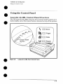
LaserJet 4L/4ML Front Control Panel – 3-9
LaserJet 4P/4MP Front (;ontrol Panel – 3-12
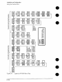
LaserJet 4P/4MP Menu Map – 3-14
Service Mode Menu Map (LaserJet 4ML/4P/4MP) -3-16
LaserJet 4L Self Test Page – 3-20
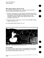
LaserJet 4MP Service Mt]de Self Test Page – 3-22
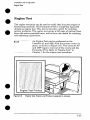
Engine Test Button and Printout (LaserJet 4L) – 3-25
Service Checkpoints – 4-2
Sample 5% Page Coverage – 4-4
Paper Feed Area Jam – 4-9
Clearing Jams from the Toner Cartridge Area – 4-10
Clearing Jams from the l’aper Guide – 4-10
Releasing Paper from the Fusing Assembly – 4-11
Clearing Jams from the Fuser Area – 4-12
Printer Functional Block Diagram – 5-2
DC Controller Loads – 5-3
Top Cover/Toner Cartridge Plunger – 5-6
Power Supply Block Diagram – 5-9
High Voltage Power Timing – 5-11
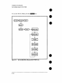
Formatter Block Diagram – 5-12
EconoMode vs. Regular F’rint – 5-18
Image Formation Block Diagram – 5-22
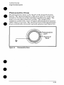
Photosensitive Drum – 5-23
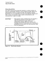
Drum Surface Potential --5-24
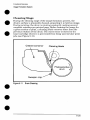
Drum Cleaning – 5-25
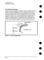
Primary Charging Roller – 5-26
Image Writing – 5-27
Image Development – 5-29
Developing Potentials – 5-30
Transferring Stage – 5-3:1
Fusing Film and Pressure Roller – 5-32
Printer Paper Path – 5-34
Oblique Roller Paper Alignment – 5-37
v
Fig
Fig
Fig
Fig
Fig
Fig
Fig
Fig
Fig
Fig
Fig
Fig
Fig
Fig
Fig
Fig
Fig
Fig
Fig
Fig
Fig
Fig
Fig
Fig
Fig
Fig
Fig
Fig
Fig
Fig
Fig
Fig
Fig
Fig
Fig
Fig
Fig
Fig
Fig
Fig
Fig
Fig
Fig
Fig
Fig
Fig
Fig
Fig
Fig
vi
6-1
6-2
6-3
6-4
6-5
6-6
6-7
6-8
6-9
6-10
6-11
6-12
6-13
6-14
6-15
6-16
6-17
6-18
6-19
6-20
6-21
6-22
6-23
6-24
6-25
6-26
6-27
6-28
6-29
6-30
6-31
6-32
6-33
6-34
6-35
6-36
6-37
6-38
6-39
6-40
6-41
6-42
6-43
6-44
6-45
6-46
6-47
6-48
6-49
Phillips vs. Posidriv Screwdrivers – 6-3
Memory Module (LaserJet 4L) – 6-4
SIMM Access Panel (LaserJet 4P/4MP) – 6-5
Power Access Door (LaserJet 4L/4ML) – 6-6
Printer Cover Screws (Laser,Jet 4L/4ML) – 6-7
Releasing the Printer Cover Rear Tabs – 6-8
Control Panel Connector (LaserJet 4P/4MP) – 6-9
Printer Cover Screws (Laser, Jet 4P/4MP) – 6-10
Cover (LaserJet 4P/4MP) – 6-11
Rear Door – 6-12
Control Panel Assembly (LaserJet 4P/4MP) -6-13
Control Panel RFI Shield (LaserJet 4P/4MP) -6-14
Formatter Shield and PCA – 6-15
DC Controller Connector&
Switch Actuator – 6-16
Gear Train Assembly – 6-17
Screw Tightening Sequence Example – 6-18
Main Motor – 6-19
Oblique Roller Assembly – 6-20
Tray Forms Size Guide – 6-21
Paper Cassette Assemblies – 6-22
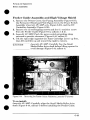
Laser/Scanner Assembly – 6-23
Fan – 6-24
Power Switch Assembly (LaserJet 4P/4MP) – 6-25
Paper Guide/Roller Assembly – 6-26
Transfer Roller -6-27
Beam-to-Drum Mirror – 6-29
Fusing Assembly – 6-30
Fusing Pressure Plate – 6-31
Upper Fusing Assembly – 6-32
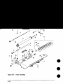
Fuser Delivery Assembly – 6-33
Lower Delivery Roller – 6-34
Lower Delivery Guide and Exit Sensor Flag – 6-35
Fuser Connector Assembly – 6-36
Upper Output Roller Assembly – 6-37
Lower Output Rollers – 6-38
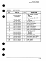
DC Controller Assembly – 6-40
Pickup Feed Roller Solenoid – 6-41
Machine Screw Locations (DC Controller PCA) – 6-43
Metal Backing Plate – 6-44
DC Controller PCA – 6-45
D-Roller – 6-46
Pickup Feed Roller Assembly (side view) – 6-47
Pickup Feed Roller Assembly (bottom view) – 6-48
Feeder Guide Assembly – 6-49
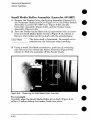
Small Media Roller Assembly – 6-50
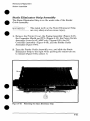
Static Eliminator Strip – 6-51
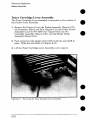
Toner Cartridge Lever Assembly – 6-52
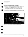
Top Cover Switch {Plunger Assembly) -6-53
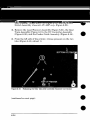
Releasing the Side Tabs – 6-.54
Fig
Fig
Fig
Fig
Fig
Fig
Fig
Fig
Fig
Fig
Fig
Fig
Fig
Fig
Fig
Fig
Fig
Fig
Fig
Fig
Fig
Fig
Fig
Fig
Fig
Fig
Fig
Fig
Fig
Fig
6-50
6-51
7-1
7-2
7-3
7-4
7-5
7-6
7-7
7-8
7-9
7-10
8-1
8-2
8-3
8-4
8-5
8-6
8-7
8-8
8-9
8-10
8-11
8-12
8-13
B-1
B-2
B-3
B-4
B-5
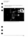
DC Controller/Scanner
Connector Location – 6-55
Input Paper Sensor Arm -6-56
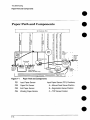
Paper Path and Components – 7-4
DC Controller PCA Components – 7-5
Top Door/T’oner Cartridge Plunger Assembly – 7-9
Engine Test Button and Printout (LJet 4L/4ML) -7-36
Defeating the Top Door Plunger (LJet 4P/4MP) – 7-37
Defeating the Exit Sensor Flag (LaserJet 4P/4MP) – 7-38
Leading Edge Adjustment – 7-43
Beam -to-Dru]m Mirror Adjustment – 7-45
Repetitive Image Defect Ruler – 7-46
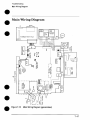
Main Wiring Diagram – 7-47
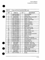
Assembly Locations – 8-7
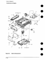
Covers and Doors (LaserJet 4L/4ML) – 8-8
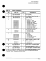
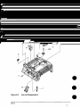
Covers and Doors (LaserJet 4P/4MP) – 8-10
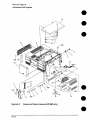
Internal Components 1 – 8-12
Internal Components 2 – 8-14
Internal Components 3 – 8-16
DC Controller Assembly – 8-18
Gear Train Plate Assembly – 8-20
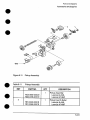
Paper Cassette (LaserJet 4L/4ML) – 8-21
Paper Cassette (LaserJet 4P/4MP) – 8-22
Pickup Assemb] y – 8-23
Fuser Assembly – 8-24
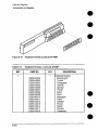
Keyboard Overlay (LaserJet 4P/4MP) – 8-26
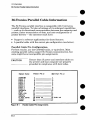
Parallel Cable Pin Assignments – B-2
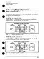
Serial Pin-outs DB-25 to DB-9 – B-3
Serial Pin-outs DB-9 to DB-9 – B-3
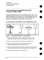
Connecting to END of a LocalTalk Network – B-4
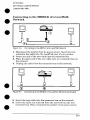
Connecting to MIDDLE of a LocalTalk Network – B-5
vii
Tbl
Tbl
Tbl
Tbl
Tbl
Tbl
Tbl
Tbl
Tbl
Tbl
Tbl
Tbl
Tbl
Tbl
Tbl
Tbl
Tbl
Tbl
Tbl
Tbl
Tbl
Tbl
Tbl
Tbl
Tbl
Tbl
Tbl
Tbl
Tbl
Tbl
Tbl
Tbl
Tbl
Tbl
Tbl
Tbl
Tbl
Tbl
Tbl
Tbl
Tbl
Tbl
Tbl
. .
Vlll
1-1
1-2
1-3
1-4
1-5
2-1
2-2
2-3
2-4
2-5
2-6
2-7
2-8
3-1
3-2
4-1
4-2
5-1
5-2
5-3
7-1
7-2
7-3
7-4
7-5
‘7-6
7-7
‘7-8
7-9
7-10
7-11
7-12
‘7-13
7-14
7-15
7-16
7-17
7-18
7-19
7-20
7-21
7-22
7-23
Printer Dimensions – 1-4
Performance Specifications -1-4
Environmental Specifications – 1-5
Electrical Specifications – 1-5
Related Documentation – 1-19
Current Requirements (Amps) – 2-2
Printer Operating Dimensions – 2-3
Toner Cartridge Environmental Conditions
Supported Media Sizes – 2-!3
Selected Paper Specifications – 2-11
Envelope Speciilcations–212
Adhesive Label Specifications – 2-14
Transparency Specifications – 2-15
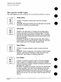
Front Panel Button Usage --3-11
Menu of Resets (LaserJet 4“P/4MP) – 3-27
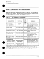
Life Expectancy of Consumi~bles – 4-3
Cleaning Printer Components – 4-6
Solenoids – 5-35
Photosensors – 5-35
Print Period Descriptions – 5-40
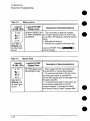
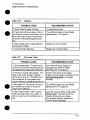
Paper Out Error -7-7
Paper Jam Error – 7-8
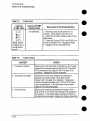
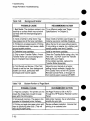
Door Open Error – 7-9
Memory Error – 7-10
Manual Feed – 7-10
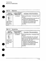
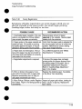
Service Error -7-11
Fuser Error --7-12
Fuser Checks – 7-12
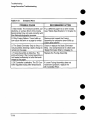
Beam Error – 7-13
Scanner Error --7-13
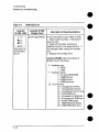
WROM
Error – 7-14
Engine Error – 7-15
Main Motor Error – 7-15
Fan Error – 7-16
Formatter Error – 7-16
NVRAM Error – 7-17
Blank Display – 7-17
Blank (White) Page – 7-24
Black Page -7-25
Faded Print -7-26
Vertical White Stripes – 7-27
Vertical Black I.ines – 7-28
Horizontal Black Lines – 7-28
– 2-4
Tbl 7-24
Tbl 7-25
Tb”l 7-26
Tbl 7-27
Tbl 7-28
Tbl 7-29
Tbl 7-30
Tbl 7-31
Tbl 7-32
Tbl 7-33
Tbl 7-34
Tbl 7-35
Tbl 8-1
Tbl 8-2
Tbl 8-3
Tbl 8-4
Tbl 8-5
Tbl 8-6
Tbl 8-7
Tbl 8-8
Tbl 8-9
Tb[ 8-10
Tb~ 8-11
Tbl 8-12
Tb\ 8-13
Repetitive Defects – 7-29
Staining -7-30
Dropout – 7-31
Character Voids – 7-31
Background Scatter – 7-32
Bottom Portion of Page Blank – 7-32
Faulty Registration – 7-33
Smeared Print – 7-34
Image Skew – 7-35
Compressed Print – 7-35
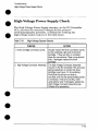
High-Voltage System Checks – 7-41
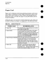
Causes of Paper Curl – 7-42
Fasteners IJsed in the Printer – 8-4
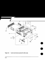
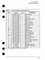
Covers and Doors (LaserJet 4L/4ML only) – 8-9
Covers and Doors (LaserJet 4P/4MP only) – 8-11
Internal Components 1 – 8-13
Internal Components 2 – 8-15
Internal Components 3 – 8-17
DC Controller Assembly – 8-19
Gear Train Plate Assembly – 8-20
Paper Cassette (LaserJet 4L/4ML) -8-21
Paper Cassette (LaserJet 4P/4MP) -8-22
Pickup Assembly – 8-23
Fuser Assembly -8-25
Keyboard Overlays (Laser,Jet 4P/4MP) – 8-26
ix
x
Chapter Contents
Product
Information
Printer Features – 1-2
Identification – 1-3
Model and Serial Numbers – 1-3
Specifications
– 1-4
Product Overview – 1-6
External Assembly Locations (LaserJet 4L/4ML) – 1-6
External Assembly Locations (LaserJet 4P/4MP) – 1-7
Internal Assembly Locations – 1-8
Safety Information
– 1-11
Laser Safety – 1-11
Laser Statement (Finland) – 1-12
Declaration of Conformity – 1-13
Toner Safety – 1-14
MSDS Information – 1-14
By mail: – 1-14
By fax: – 1-14
Ozone Emission – 1-14
FCC Statement
VCCI Statement
(Class B) – 1-15
(Japan)
– 1-16
Service Approach – 1-17
Exchange Program – 1-17
Ordering Parts – 1-17
Ordering Consumables – 1-17
Ordering Related Documentation – 1-18
Print Utilities – 1-19
Technical Assistance
– 1-20
HP ASAP 1-800-333-1917 (U.S.) – 1-20
HP FIRST -1-20
HP FIRST, U.S. – 1-20
HP FIRST, Europe – 1-20
HP AUDIO-TIPS – 1-21
HP CompuServe Forum – 1-21
Customer Information Centers – 1-21
Customer Support Center (Assist Line) – 1-21
European Customer Support Center – 1-22
Other Areas – 1-22
‘
Chapter 1
Contents Page 1
CI!-mpttwcamtemrts
2 Q@a=ating
Rmq@7mflmmfx
‘o
Site Requirements
– 2-2
Operating Environment – 2-2
Printer Space Requirements – 2-3
●
The HP 92274A Toner Cartridge – 2-4
Storage Conditions – 2-4
Storing Opened Toner Cartridges – 2-5
Toner Cartridge Handling Suggestions – 2-6
Refilled Toner Cartridges – 2-7
Recycling Toner Cartridges – 2-7
Media Specifications
– 2-8
Media Sizes Supported – 2-9
Media Selection Guidelines – 2-10
Envelope Specifications – 2-12
Adhesive Label Specifications – 2-13
Transparency Specifications – 2-15
Storing Print Media – 2-16
Shipping Print Media – 2-16
Chapter 2
Contents Page 1
0&@x5w’ Q3mr&?mts
hs’tdktimoi
and Cmfigmlmtilm
Unpacking and Installation – 3-2
A. Choose the best location. – 3-2
B. Unpack the printer. – 3-2
C. Check package contents. – 3-3
D. Install the toner cartridge. – 3-3
E. Load the paper cassette. – 3-4
F. Attach the interface cable(s). – 3-4
G. Attach the power cord. – 3-5
H. Attach the Help Labels (Lase’Jet 4L/4ML only) – 3-6
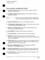
I. Install Printer Drivers and Utilities (optional) – 3-7
How to Obtain Printer Drivers – 3-7
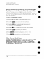
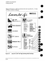
Using the Printing Software Package – 3-8
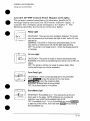
Using the Control Panel – 3-9
LaserJet 4L/4ML Control Panel Overview – 3-9
The LaserJet 4L/4ML Lights – 3-10
The LaserJet 4L/4ML Front Panel Button – 3-11
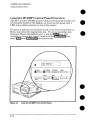
LaserJet 4P/4MP Control Panel Overview – 3-12
LaserJet 4P/4MP Control Panel Display and Lights – 3-13
Service Mode (LaserJet 4ML/4P/4MP) – 3-15
LaserJet 4ML – 3-15
LaserJet 4P/4MP – 3-15
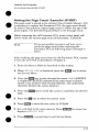
Setting the Page Count (LaserJet 4P/4MP) -3-17
Setting the Cold Reset Default (LaserJet 4P/4MP) -3-18
Other Service Mode Items – 3-18
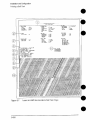
Printing a Self Test – 3-19
LaserJet 4L/4ML: – 3-19
LaserJet 4P/4MP: – 3-19
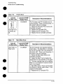
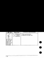
The LaserJet 4L Self Test Fields – 3-21
The LaserJet 4ML/4P/4MP Self Test Fields – 3-23
Continuous Self Test – 3-24
LaserJet 4L/4ML: – 3-24
LaserJet 4P/4MP: – 3-24
Engine Test – 3-25
(continued
Chapter 3
on back)
Contents Page 1
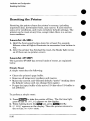
Resetting the Printer – 3-26
LaserJet 41J4ML: – 3-26
LaserJet 4P/4MP: – 3-26
Simple Reset – 3-26
The Menu of Resets – 3-27
The Cold Reset (LaserJet 4ML/4P/4MP) – 3-28
LaserJet 4ML: – 3-28
LaserJet 4P14MP: – 3-28
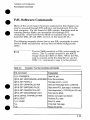
PJL Software Commands – 3-29
Contents Page 2
Chapter 3
chapter CkDntc?nts
4 Maintenancx2
●
a
Service Checkpoints
– 4-2
Life Expectancy of Consumables
– 4-3
Toner Cartridge Life – 4-4
Saving Toner with EconoMode – 4-5
Cleaning Printer Components
Cleaning Spilled Toner – 4-7
– 4-6
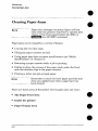
(leafing Paper Jams – 4-8
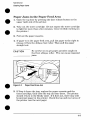
Paper Jams in the Paper Feed Area – 4-9
Paper Jams Inside The Printer – 4-10
Paper Jams in the Paper Output Area – 4-12
Chapter 4
Contents Page 1
Chapter Contents
5 Functional Overview
●
‘a
a
m
m
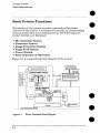
Basic Printer Functions – 5-2
DC Controller/Power
System – 5-3
Print Engine Control – 5-5
Laser and Scanner Drive – 5-5
Paper Motion Monitoring and Control – 5-5
Top Door/Toner Cartridge Microswitch (SW201) – 5-6
Engine Test MicrosWitch (SW301) -5-7
Motors – 5-7
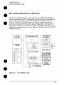
Power System (on DC Controller PCA) – 5-8
AC Power Distribution – 5-8
DC Power Distribution – 5-8
Overcurrent/Overvoltage Protection – 5-10
Intelligent ON/OFF (LaserJet 41J4ML only) – 5-10
High Voltage Power Distribution – 5-11
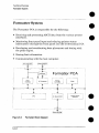
Formatter System – 5-12
CPU – 5-13
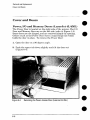
Read Only Memory (ROM) -5-13
Random Access Memory (RAM) -5-13
Non-Volatile Memory (NVRAM) – 5-14
Parallel Interface – 5-14
High Speed (Yes/No) – 5-14
Advanced Functions (On/Off) – 5-14
Serial I/O (LaserJet 4P/4MP) -5-15
Pacing (Serial Modes of Operation) – 5-15
LocalTalk I/O (LaserJet 4ML/4MP) – 5-15
Control Panel – 5-16
LaserJet 4L/4ML – 5-16
LaserJet 4P/4MP – 5-16
Resolution Enhancement (REt) – 5-17
Print Density Adjustment – 5-17
EconoMode – 5-18
Memory Management – 5-19
Memory Enhancement technology (MEt) – 5-19
Image Adapt (LaserJet 4L/4ML) – 5-20
Page Protect – 5-20
PJL Overview – 5-21
(continued
Chapter 5
on back)
Contents Page 1
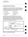
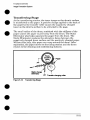
Image Formation System – 5-22
Photosensitive Drum – 5-23
Drum Sensitivity – 5-24
Cleaning Stage – 5-25
Conditioning Stage – 5-26
Writing Stage – 5-27
Developing Stage – 5-29
Transferring Stage – 5-31
Fusing Stage – 5-32
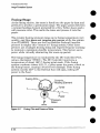
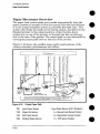
Paper Feed System – 5-33
Paper Movement Overview – 5-34
Solenoids – 5-35
Photosensors – 5-35
Paper Out Sensor (PS2) – 5-35
Input Paper Sensor (PS1) – 5-36
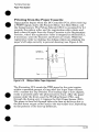
Printing from the Paper Cassette – 5-37
Manual Feed Printing – 5-38
Small Media Rollers (LaserJet 4P/4MP) – 5-38
Paper Jam Detection – 5-39
Power-On Jams – 5-39
Pickup Jams – 5-39
Delay Jams – 5-39
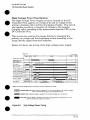
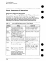
Basic Sequence of Operation – 5-40
Standard Printer Operation – 5-40
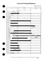
General Timing Diagram – 5-41
Contents Page 2
Chapter 5
Cx’-?.apbfckmiw?i’Nts
JRmmKmd and W@wmnm?nt
Removal and Replacement
Strategy – 6-2
Required Tools – 6-3
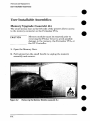
User Installable Assemblies – 6-4
Memory Upgrade (LaserJet 4L) – 6-4
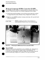
Memory/Language SIMMS (LaserJet 4P/4MP) – 6-5
Cover and Doors – 6-6
Power, I/O and Memory
Printer Cover (LaserJet
Printer Cover (LaserJet
Rear Door – 6-12
Control Panel (LaserJet
Doors (LaserJet 41J4ML) -6-6
4L/4ML) -6-7
4P/4MP) -6-9
4P/4MP) ~ 6-13
Left Side Assemblies – 6-15
Formatter Shield and PCA – 6-15
Gear Train Assembly – 6-17
Main Motor – 6-19
Front Assemblies – 6-20
Front Oblique Roller Assembly – 6-20
Paper Cassette Assembly – 6-21
Tray Forms Size Guide (LaserJet 4L/4ML) -6-21
Compression Springs – 6-22
Internal Assemblies – 6-23
Laser/Scanner Assembly – 6-23
Fan – 6-24
Power Switch Assembly (LaserJet 4P/4MP only) -6-25
Paper Guide/Top Oblique Roller Assembly – 6-26
Transfer Roller and Guide – 6-27
Transfer Roller Bushings – 6-28
‘1
Beam-to-Drum Mirror Assembly – 6-29
(continued on back)
Chapter 6
Contents Page 1
Rear Assemblies – 6-30
Fusing Assembly – 6-30
Fusing Assembly Components – 6-31
Pressure Plate – 6-31
Upper Fusing Assembly
(Teflon Sleeve and Heater Element) -6-32
Pressure Roller – 6-33
Delivery Assembly – 6-33
Lower Delivery Roller – 6-34
Lower Delivery GuidelExit Sensor Flag – 6-35
Connector Assembly (Fuser Entrance Guide) – 6-36
Upper Output Roller Assembly – 6-37
Lower Output Rollers – 6-38
a
m
\
,,~
Bottom Assemblies – 6-39
DC Controller Assembly – 6-39
Pickup Solenoid (SL2) – 6-41
DC Controller Fuses – 6-42
High Voltage Connector Assembly – 6-42
DC Controller PCA – 6-43
Pickup Feed D-Roller – 6-46
Pickup Assembly – 6-47
Feeder Guide Assembly and High Voltage Shield – 6-49
Small Media Roller Assembly (LaserJet 4P/4MP) -6-50
Static Eliminator Strip Assembly – 6-51
Toner Cartridge Lever Assembly – 6-52
Top Door Switch (Plunger Assembly) – 6-53
DC Controller/Scanner Connector Assembly -6-54
PS1 Input Paper Sensor Arm – 6-56
0. .,
Contents Page 2
Chapter 6
...
-’
TmlldMeshmtintg
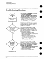
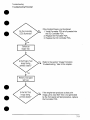
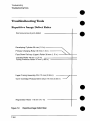
Troubleshooting
Flowchart – 7-2
Paper Path and Components
– 7-4
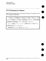
DC Controller Diagram – 7-5
Printer Error Troubleshooting – 7-6
LaserJet 4L/4ML: – 7-6
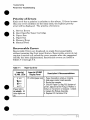
LaserJet 4P/4MP: – 7-6
Priority of Errors – 7-7
Recoverable Errors – 7-7
Service Errors – 7-11
LaserJet 4L/4ML – 7-11
LaserJet 4P/4MP – 7-11
Clearable Warnings (LaserJet 4P/4MP) – 7-18
Image Formation
Troubleshooting
– 7-19
Engine Test – 7-36
Engine Test Button Location – 7-36
Printing an Engine Test - LaserJet 4L/4ML – 7-36
Printing an Engine Test - LaserJet 4P/4MP – 7-37
Half Self Test Functional
Drum Rotation Functional
High-Voltage
Check – 7-39
Check – 7-40
Power Supply Check – 7-41
Paper Curl – 7-42
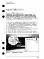
Adjustment Procedures – 7-43
Leading Edge Adjustment – 7-43
Beam-to-Drum Mirror Adjustment – 7-44
Troubleshooting Tools – 7-46
Repetitive Image Defect Ruler – 7-46
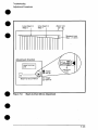
Main Wiring Diagram – 7-47
Chapter 7
Contents Page 1
Chapter Contents
$
a
,’
m
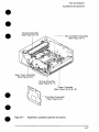
Parts and Diagrams
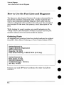
How to Use the Part Lists and Diagrams – 8-2
Orderhw Parts – 8-2
Orderin~ Consumables – 8-3
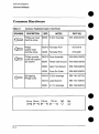
Common Hardware – 8-4
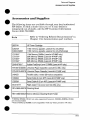
Accessories
Assembly
and Supplies -8-5
Locations -8-7
Covers and Doors (LaserJet 4L/4ML) -8-8
Covers and Doors (LaserJet 4P/4MP) -8-10
Internal Components
1 – 8-12
Internal Components
2 – 8-14
Internal Components
3-8-16
DC Controller Assembly
– 8-18
Gear Train Plate Assembly
-8-20
Paper Cassette (LaserJet 4L/4ML) – 8-21
Paper Cassette (LaserJet 4P/4MP) – 8-22
Pickup Assembly
Fuser Assembly
– 8-23
-8-24
Keyboard Overlay (LaserJet 4P/4MP) – 8-26
Chapter 8
Contents Page 1
AppendixA
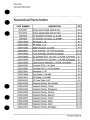
Parts Index
Appendk B
170IMorrnation
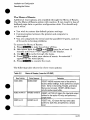
Product Itiormation
Product Information
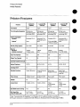
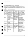
Printer Features
Printer Features
Features
Print Speed
I
LaserJet 4L
(C2003A)
I
LsaarJet 4ML
(C2015A)
I 4ppm
Text &Graphics Resolution
Printer Language
Stsndard
300 dpi; @JS
Res Enhancement
technology (REt)
300 dpi; plus
Res Enhancement
technology (REt)
Enhanced PCL 5
Enhanced PCL 5
PostScript Level 2
None
None
Optionat
Monthly Usage (pages)
I Upto6000
UP tO 8000
Output Tray Capacity
I 50
50
600 dpi; plus
600dpi; plus
Res Enhancement
technology (REt)
Res Enhancement
technology (REt)
Enhanced PCL 5
Enhanced PCL 5
PostScript Level 2
None
PS L2 (with SIMM
+4 Mb opt memory)’
up to 8000
UP to 8000
I
1
45 PCL, 35 PS
o
*
Standard Interfaces
Power Control
Parallel (13-tronics)
1 bteligentC)n/Ofl
Parallel (8i-tronics)
LocalTalk
Intelligent On/Ofl
=--l=Setial (9 pin)
Parallel (8i-tronics)
I Power switch
Serial (9 pin)
Parallel (!3-tronics)
LocalTalk
lF’owerswitch
1
EconoMode (toner saving)
Yes
Min. Paper Size
(using flat paper path)
3 x 6.75 inch
(76 x 171 mm)
1
See “Accessories& Supplies”in Cha ter 8 for optionproductnumbers.
2 Printermemoryis optimizedwith MemoryEnhancementTechnology(MEt).
1-2
I
Product Information
Identification
Identification
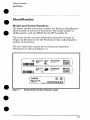
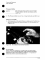
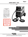
Model and Serial Numbers
The model number and serial numbers are listed on identification
labels located on the rear of the printer. The model number is
alphanumeric, such as C2003A for the HP LaserJet 4L.
The serial number contains information about the Country of
Origin, the Revision Level, the Production Code, and production
number of the printer.
The rear labels also contain power rating and regulatory
information as shown in Figure 1-1.
I
I
Figure
1-1
Sample Model and Serial Number Labels
1-3
Product Information
Specifications
Specifications
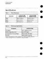
Table 1-1
Printer Dimensions
LaserJet 4L/4ML
(C2003A/C2015A)
Dimension
Width
LaserJet 4P/4MP
(C2005A/C2040A)
Depth
137 cm (14.5 in.)
,
116.5 cm (6.5 in.)
Heiaht
Table 1-2
Performance
I
CATEGORY
139 cm (15.5 in.)
1
118 cm (7 in.)
I
SPECIFICATION
Up to 4 pages per minute
Monthly Usage (Duty Cycle)
Up to 8000 pages
Life Expectancy of toner cartridge**
Approximately
3000 pages
lApproximately
34 seconds
*Actual speed depends on data complexity and software handling efficiency.
**Toner Cartridge life can be extended by using EconoMocle.
1-4
I
Specifications
Print Speed *
I First Print
●
40 cm (15.75 in.)
36 cm (14,25 in.)
I
I
Product Information
Specifications
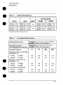
Table 1-4
Electrical Specifications
WATTS (typical)
VOLTS
FREQ
AMPS*
120 Vact10%
100 Vac ? 10%
50/60 Hz k 2 Hz
50/60 Hz? 2 Hz
36
220 Vac f 1O%
240Vac k 10%
50/60 Hz+ 2 tiz
50/60 Hz k 2 Hz
,8
“
4L14ML
I
4P14MP
*Operating current requirements.
Table 1-3
Environmental
Specifications
Operating Environment
‘temperature: 10° C to 32.5° C (50° F to 90.5° F)
Iumidity: 20-80% (no condensation)
Storage Environment
(not including toner cartridge)
‘temperature: -20° to 60° C (-4° to 140”F)
Iumidity: 15-90% (no condensation)
Acoustic Emissions
4L
4P
4ML
4MP
Operation position (per ISO 9296,
DIN 45635,T.1 9):
Printing
LPA dB(A)
<48
<49
<51
<49
Standby
LPA dB(A)
<22
<33
<22
<31
Bystander 1m (per ISO 7779,
DIN 45635,T.1 9):
Printing
LPA dB(A)
<45
<46
<47
<46
Standby
LPA dB(A)
<22
<30
<22
<29
Sound
Power
(per ISO 9296):
Printing
LPA dB(A)
<5.9
<6.0
<6.1
<6.0
Standby
LPA dB(A)
<3.5
<4.4
<3.6
<4,4
1-5
Product Information
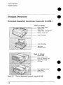
Product Overview
Product Overview
External Assembly
Figure 1-2
1-6
Locations
(LaserJet 4L/4ML)
External Assembly Locations, Laserdef 4L/4ML
Product Information
Product Overview
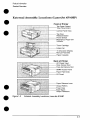
External Assembly Locations
(LaserJet 4P/4MP)
1-7
Product Information
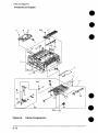
Product Overview
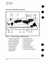
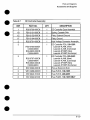
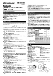
Internal Assembly Locations
Figure 1.4
Internal Assembly Locations (all printers)
1, Face-Down Output Rollers
10, Pickup Feed D-Roller
2. Upper Fusing Assembly
11. Transfer Roller Assembly
3. Laser/Scanner
12, Photosensitive
Drum
4. Primary Charging Roller
13. DC Controller PCA
5. Beam-to-Drum
14. Paper Cassette
Mirror
6. Developing Cylinder
15. Fusing Pressure Roller
7. Toner Cartridge
16. Face-up Delivery Roller
8. Registration Roller
17. Face-Up/Face-Down
9. Oblique Rollers
1-8
Assembly
Deflector
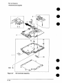
Product Information
Product Overview
—
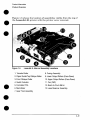
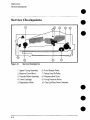
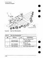
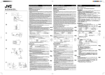
Fim.me 1-5 shows the location of assemblies visible from the ton of
th; LaserJet
4L printer with the printer cover removed.
‘
~lgure 1-5
m
LaserJet 4L Internal Assembly Locations
1. Transfer Roller
8. Fusing Assembly
2. Paper Guide/Top Oblique Roller
9. Lower Output Rollers (Face-Down)
3. Front Oblique Roller
10. Upper Output Rollers (Face-Down)
4, Switch Actuator
11. Fan (FM1)
5. Formatter PCA
12. Beam-to-Drum
Mirror
6. Main Motor
13. Laser/Scanner
Assembly
7. Gear Train Assembly
●
1-9
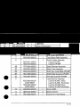
Product Information
Product Overview
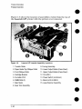
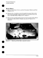
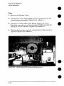
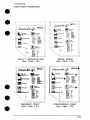
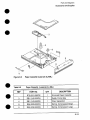
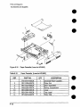
Figure 1-6 shows the location of assemblies visible from the top of
the LaserJet 4P printer with the printer cover removed.
Figure 1-6
LaserJet 4P Internal Assembly Locations
1. Transfer Roller
2. Paper Guideflop
9. Fusing Assembly
Oblique Roller
10. Lower Output Rollers (Face-Down)
3. Front Oblique Roller
11. Upper Output Rollers (Face-Down)
4. Cartridge Bracket
12. Fan (FM1)
5. Formatter PCA
13. Power Switch (not shown)
6. SIMM Slots (3)
14, Beam-to-Drum
Mirror
7, Main Motor
15, Laser/Scanner
Assembly
8. Gear Train Assembly
1-1o
Product Information
Safety Information
Safety Information
Laser Safety
The Center for Devices and Radiological Health (CDRH) of the
U.S. Food and Drug Administration implemented regulations for
laser products manufactured since August 1, 1976. Compliance is
mandatory for products marketed in the United States.
This printer is certified as a “Class 1“ laser product under the U.S.
Department of Health and Human Services (DHHS) Radiation
Performance Standard according to the Radiation Control for
Health and Safety Act of 1968. Since radiation emitted inside this
printer is completely confined within protective housings and
external covers, the laser beam cannot escape during any phase of
normal user operation.
Never operate or service the printer with the
protective cover removed from the
Laser/Scanner Assembly. The reflected beam,
although invisible, can damage your eyes.
1-11
Product Information
Safety Information
Laser Statement
(Finland)
The following applies to printer operation and servicing in Finland.
LASERTURVALLISUUS
LUOKAN 1 LASERLAITE
KLASS 1 LASER APPARAT
HP LaserJet(s)4L, 4ML, 4P &. 4MP Iaserkirjoitin on kayttajan kannalta turvallinen
luokan 1 laeerlaite. Normaalissa
lasersateen
kaytossa kirjoittimen
suojakotelointi
estaa
paasyn laitteen ulkopuolelle.
Kirjoittimen
on hyvaksynyt
Stikotarkastuskeskus.
Suomessa laserturvallisuuden
Laitteen turvallisuusluokka
osalta
on maaritetty
paatoksen N:o 472/1985 ja standardin EN 60825 (1991)
valtioneuvoston
mukaisesti.
VAROITUS ! Laitteenkayttaminenmuullakuin kayttoohjeessamainitullatavalla
saattaaaltistaakayttajanturvallisuusluokan1 ylittavalle nakymattomalle
lasersateilylle.
VARNING ! Om apparatenanvandspa annatsattw i bruksanvisning
specificerats,kan anvandarenutsattasfor osynliglaserstr~lning,somoverskrider
griinsenfor laserklass1.
HUOLTO HP LaserJet(s)4L, 4ML,4P & 4MP-kirjoittimensisalliiei ole kayttajan
huollettavissaoleviakohteita.Laitteensaaavataja huoltaaainoastaansen
huoltamiseenkoulutettuhenkilo.Tallaiseksihuoltotoimenpiteeksi
ei katsota
variainekasetinvaihtamista,paperiradanpuhdistustatai muitakayttajiin
kasikirjassalueteltuja,kayttajantehtavaksitarkoitettujayllapitotoimia,jotka
voidaansuorittaailmanerikoistyokaluja.
VARO ! Mikalikirjoittimensuojakoteloavataan,olet alttiinanakymattomalle
lasersateilyllelaitteenollessatoiminnassa.~a katsosateeseen.
VARNING ! Omlaserprinternsskyddsholjeoppnasd5.apparatenar i fanktion,
utsattasanvandarenfor osynliglaserstr~lning.Betraktaej str?alen.
Tiedotlaitteessakaytettavanlaserdiodinsateilyominaisuuksista:
Aallonpituus777-795nm
Teho 5 mW
Luokan3B laser
1-12
Product Information
Safety Information
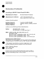
Declaration
●
●
According
of Conformity
to ISO/IEC
Guide
22 and EN 45014:
Manufacturer’s
Name:
Hewlett-Packard
Company
Manufacturer’s
Address:
11311 Chinden Boulevard
Boise, Idaho 83714-1021, USA
declares, that the product
LaserJet 4L/4ML/4P/4MP
C2003A, C2015A, C2005A, C2040A
All
Product
Name(s):
Model Number(s):
Product
Options:
conforms to the following Product Specifications:
Safet~
EMC:
EN 60950:1988+ A1,A2
IEC 825:1984 + A1:1990 laser class 1
CISPR-22:1985 /
EN 50082-1:1992
IEC 801-2:1991/
IEC 801-3:1984/
IEC 801-4:1988/
EN 55022:1988
class Bl)
prEN55024-2:1992
- 3kV CD, 8 kV AD
prEN55024-3:1991
- 3V/m
prEN55024-4: 1992-1 kV Power lines
Supplementary
Information:
The product herewith complies with the requirements of the Low
Voltage Directive 73/23/EEC and the EMC Directive 89/336/EEC.
a
1) The product was tested in a typical configuration with
Hewlett-Packard Personal Computer and Test Systems.
●
Office of Quality Manager
Boise, Idaho USA
June 15, 1993
European Contact: Your Local Hewlett-Packard Sales and Service OffIce or
Hewlett-Packard GmbH, Department ZQ / Standards Europe, Herrenberger
Strae 130, D-7030 Bblingen (FAX + 49-7031-14-3143)
o
1-13
Product Information
Safety Information
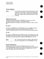
Toner Safety
Note
In case of toner spills, skin and clothing are best
cleaned by removing as much toner as possible
with a dry tissue, then washing with cold water.
Hot water causes toner to permanently set into
clothing.
●
MSDS Information
A Material Safety Data Sheet (MSDS) for toner or any other
chemical used in the printer is available through
Hewlett-Packard’s
Customer Information Center by either mail or
fax.
By mail:
To obtain an MSDS for the HP 92274A toner cartridges through
the mail, call the Customer Information Center (CIC) at
1-800-752-0900 between 6 A.M. and 5 P.M. Pacific Standard Time.
By fax
To obtain an MSDS for the HP 92274A toner cartridges by fax, call
HP ASAP (Automated Support Access Program) at 1-800-333-1917
and follow the instructions for using the HP FIRST fax service.
Note
See “Technical Assistance” later in this chapter
for more information on the HP FIRST service.
Ozone Emission
These printers do not use high voltage corona wires in the
electrophotographic
process, and therefore generate no measurable
ozone gas (03). The printers instead use charging rollers in the
toner cartridge and in the print engine.
1-14
●
Product Information
FCC Statement
(Class B)
FCC Statement (Class B)
Note: This equipment has been tested and found to comply with
the limits for a Class B digital device, pursuant to part 15 of the
FCC rules. These limits are designed to provide reasonable
protection against harmful interference in a residential
installation. This equipment generates, uses, and can radiate radio
frequency energy and, if not installed and used in accordance with
the instructions, may cause harmful interference to radio
communications. However, there is no guarantee that interference
will not occur in a particular installation. If this equipment does
cause hmful
interference to radio or television reception, which
can be determined by turning the equipment off and on, the user is
encouraged to try to correct the interference by one or more of the
following measures:
●
●
Reorient or relocate the receiving antenna.
Increase the separation between the equipment
and the receiver.
●
Connect the equipment into an outlet on a circuit different from
that to which the receiver is connected.
●
Consult the dealer or an experienced
help.
radio/TV technician
for
Any changes or modifications not expressly approved by
Hewlett-Packard could void the user’s authority to operate this
equipment.
Note
Use of a shielded interface cable is required to
comply within the Class B limits in Part 15 of
FCC rules.
1-15
Product Information
VCCI Statement (Japan)
VCCI Statement (Japan)
The VCCI statement below is required in Japan. It is similar to the
FCC regulatory statement.
-
1-16
Product Information
Service Approach
●
●
e
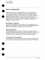
Service Approach
Repair of the printer normally begins with use of the printer’s
internal diagnostics in conjunction with the troubleshooting
procedures in Chapter 7. Once a faulty part is located, repair is
accomplished generally by assembly-level replacement of Field
Replaceable Units (FRUS). Some mechanical parts maybe
repaired at the sub-assembly.
PCA component replacement is not
supported by HP. Part numbers for all FRUS are located in
Chapter 8 of this manual.
Exchange
Program
HP offers remanufactured assemblies for some selected parts.
These are identified in Chapter 8 and can be ordered through HP’s
Parts Direct Ordering, or Parts Center Europe (PCE).
Ordering Parts
Field replaceable part numbers are found in Chapter 8 of this
manual. Replacement parts may be ordered from HP’s Parts Direct
Ordering, or Parts Center Europe (PCE). Adresses and phone
numbers for both organizations are also found in Chapter 8.
Ordering Consumables
Consumables may be ordered directly from Hewlett-Packard.
The
phone numbers for ordering consumables are found in Chapter 8.
1-17
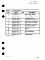
Product Information
Service Approach
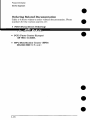
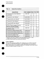
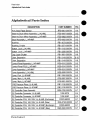
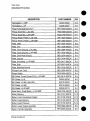
Ordering Related Documentation
Table 1-5 shows where to order related documentation.
numbers for the various sources are:
.
PDO (Parts Direct Ordering)
1-S00-227-8164 (U.S. only)
.
PCE (Parts Center Europe)
(49 7031) 14-2253.
e HP’s Distribution
Center
303-353-7650 (U.S. Ody)
(HPD)
Phone
Product Information
Service Approach
Table 1-5
Relaiecl Documentation
DESCRIPTION
PART NUMBER
PDO
I PCE
HPD
I
HP LaserJet Family Quick Reference
Service Guide
x
5961-0531
x
HP LaserJet 4L User’s Manuall
C2003-90901
xx
HP LaserJet 4ML User!s Manuali
C2015-90901
xx
HP LaserJet 4P User’s Manualf
C2005-90943
xx
HP LaserJet 4MP User% Manual’
C2040-90912
xx
HP PCL5 Printer Language Technics/
Reference Information Package
5961-0601
xx
HP LaserJet Printer Family Paper
Specifications Guide
5002-1801
x
HP LaserJet 4L Software Solutions Pkg, f
C2003-60122
x
HP LaserJet 4ML Windows Solutions Pkg. 1
C201 5-60101
x
HP LaserJet 4ML Macintosh Solutions Pkg.1
C201 5-60113
HP LaserJet 4P Software Packl
C2OO5-6O1O7
HP LaserJet 4MP Software Packl’2
C2040-60101
Shiu~ed with Drinter. (English version Dart number is shown
tra;~lations a;e available --see your loc~l HI Sales Office.)
.z Includes DOS. Windows and Macintosh solutions.
Print
x
;
~
x
1
Other
Utilities
HP provides several utilities for enhancing use of the LaserJet
printers in DOS, MS Windows, and Macintosh environments.
More information on specific utilities is included with each of the
software packs listed in Table 1-5.
1-19
Product Information
Technical
Assistance
Technical Assistance
HP ASAP 1-800-333-1917
(U. S.)
HP ASAP (Automated Support Access Program) provides free
technical support information 24 hours a day, 7 days a week. The
ASAP system includes HP FIRST and HP AUDIO-TIPS, both
explained below. The ASAP service requires a touch-tone phone.
HP FIRST
HP FIRST (Fax Information Retrieval Support Technology) is a
phone-in fax service providing technical information for HP
LaserJet users as well as service personnel. Receiving a fax
requires a group 3 facsimile machine or fax card. Service-related
information includes:
Service notes (HP Authorized dealers).
Application notes.
Product Data Sheets.
Material Safety Data Sheets (MSDS).
Typeface and accessory information.
Printer support software information.
Toner information.
Driver request form and Software Matrix.
HP FIRST,
U.S.
Call the HP ASAP system (1-800-333-1917)
prompts to enter HP FIRST.
HP FIRST,
and follow the voice
Europe
Call HP FIRST at one of the following numbers:
U. K., 0800-96-02-71
Netherlands, 06-0222420
Belgium (Dutch), 078-111906
Germany, 0130-810061
Switzerland (German), 155-1527
Austria, 0660-8128
For English service outside the above countries, (31) 20-681-5792
1-20
Product Information
Technical
Assistance
HP AUDIO-TIPS
a
●
HP AUDIO-TIPS, available within HP ASAP, is an interactive
voice response system providing pre-recorded answers to the
questions most frequently asked by HP LaserJet printer users.
Helpful “System Maps” to the HP AUDIO-TIPS recordings are
available by fax through HP FIRST.
HP CompuServe
Forum
CompuServe members can download a variety of support materials
including product data sheets, software application notes, and
printer drivers for many popular software applications. Members
may also post and reply to questions in an interactive format. To
access the HP Forum, type GO HPPER at any prompt. For more
information, or to join CompuServe, call 1-800-524-3388.
Customer Information
Centers
For further technical assistance, service-authorized
HP and dealer
service personnel can contact the nearest Hewlett-Packard
Customer Information Center, 1-800-752-0900 in North America.
Customer Support Center (Assist Line)
The HP Customer Support Center, (208-323-2551) is available to
answer technical questions regarding setup, configuration,
installation and operation of HP printers in the PC and Macintosh
environments. The CSC Assist Line is available weekdays from
7AM to 6 PM Mountain Time (Wednesdays until 4 PM).
a
Questions relating to operating systems such as MS-DOS and
UNIX, your network conjuration,
or network operating system
cannot be answered by the Center and should be referred to your
authorized reseller.
1-21
Product Information
Technical
Assistance
European
Customer Support Center
The HP European Customer Support Center, located in
Amsterdam, Holland, is open from 8:30 am to 6:00 pm central
European time (Wednesdays until 4:00 pm). Multilingual customer
support representatives can answer technical questions similar to
the U.S. CSC, described on the previous page. This service is
available at no charge for a period equivalent to the original HP
hardware warranty period.
●
●
Each time you call the HP European Customer Support Center,
you will be required to provide the printer’s serial number and
original date of purchase.
To receive a fax listing the supported languages on a countries’
phone number, call HP FIRST (refer to “HP FIRST,” earlier in this
section). You can also call the nearest HP sales and service office to
obtain the telephone number for the Center. The Center features
automated call-routing technology, so you will receive faster
service if calling from a touchtone phone or tone dialer.
Other Areas
Outside of North America and Europe, contact your local HP sales
office for assistance in obtaining technical support.
a
●
●
1-22
2
=.~
●
Operating Requirements
Operating Requirements
SiteRequirements
Site Requirements
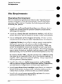
Operating Environment
The environmental specifications listed in the “Specifications”
section of Chapter 1 must be maintained to ensure the proper
operation of this printer. Consider the following points before
installing the printer:
Install in a well-ventilated, dust-free area. (Excess dust or
smoke will contaminate the printer’s Beam-to-Drum mirror,
affecting print quality. )
Install on a hard, flat and continuous surface, with all four
printer feet level. Do not install on carpet or other soft surfaces.
Ensure adequate power supply circuitry. Printer current
requirements can be found under “Specifications,” in Chapter 1.
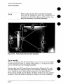
Lighting Flicker: In an effort to reduce energy consumption,
the fuser is turned on only when needed during printing.
During standby mode, the fuser is not kept warm. When the
printer is installed in a home, the instant-on fuser may cause
some house lights to flicker when printing. This phenomenon is
seen in many instant-on products, such as copiers, and will NOT
affect printing, nor will it harm the electrical system in any way.
To reduce a flicker effect, plug the printer into a different outlet
that may be on a separate circuit, or try fluorescent lighting. If
possible, add to the room’s natural lighting. (Surge suppressers
will not prevent flickering lights.)
Install where there is stable temperature and humidity,
with no abrupt changes (away from water sources, humidifiers,
air conditioners, refrigerators, or other major appliances).
Install away from direct sunlight, open flames, or ammonia
fumes. If the printer is placed near a window, make sure the
window has a curtain or blind to block any direct sunlight.
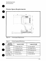
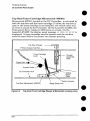
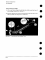
Install with enough space around the printer for proper
access and ventilation (see Figure 2-l).
2-2
Operating Requirements
Site Requirements
;~
.... ;..
‘ m
~ “~‘1
Printer Space Requirements
B
A
c
; ...................
,.,
~, -----””----------”?
\
‘i\\
\ ‘,‘,;,
II
,--,’. . ,-------------
------ *j
F
F.-.
Hgwe z--l
-i-able 2-1
m
----
wmer
.
space ~equ~remenls
Printer Operating
Operating
Dimensions
I
-“==4
Dimensions
LaserJet 4L/4ML
I
LaserJet 4P/4MP
A (l-m)))
I 14 inches (35.5cm)
El (Dqm)
14.5 inches (37 cm)
15.5 inches (39 cm)
C (Width)
14.25 inches (36 cm)
15,75 inches (40 cm)
D (Rear Dow)
I 2 inches (5 cm)
E (Height - Top
Door Cqoxw))
I
13 inches (33 cm)
I
I 15 inches (38 cm)
I
I 2 inches (5 cm)
I
14 inches (35 cm)
2-3
Operating Requirements
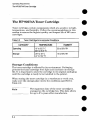
The HP 92274A Toner Cartridge
The HP 92274A Toner Cartridge
Toner cartridges contain components which are sensitive to light,
temperature, and humidity. Follow the recommendations
in this
section to ensure the highest quality and longest life of HP toner
cartridges.
Table 2-2
Toner Cartridge Environmental
Conditions
1
CATEGORY
I
1
I
TEMPERATURE
I
HUMIDITY
Operating
10° to 32,Y c
(50° to 90.5° F)
35 tO 85% RH
Storage
-20° to 40° c
(-4° to 104° F)
15 to 90% RH
Storage Conditions
The toner cartridge is affected by its environment. Packaging
protects the toner cartridge from light and increases its storage
life. It is important to store the cartridge in its original packaging
until the cartridge is ready to be installed in the printer.
When storing the toner cartridge in a warehouse or work area,
make sure the storage place meets the conditions specified in
Table 2-2.
Note
2-4
The expiration date of the toner cartridge is
stamped on the cartridge box. This date allows
for up to 2V2 years after manufacture.
I
Operating Requirements
The 1+ 92274A Toner Cartridge
●
●
Storing Opened Toner Cartridges
Because the cartridge does not have a shutter to cover the laser
beam access slot, it should be kept inside the printer until empty.
Toner cartridges which have had the toner sealing tape removed
are also more vulnerable to environmental extremes (such as high
humidity).
If the toner cartridge must be removed from the printer, always
store the cartridge:
Inside the protective
bag in which it was originally
packaged.
In a dark cabinet, away from direct sunlight.
Correct side up and in a horizontal
end).
In a temperature
between
position (not standing on
10° and 35° C (50° -95° F).
Away from ammonia or other organic solvent fumes.
CAUTION
Never ship the printer with a toner cartridge
installed. Excessive vibration during shipping
can cause toner to leak, contaminating the
printer.
Never expose the toner cartridge to direct
sunlight, or to room light for more than a few
minutes. Bright light and direct sunlight can
permanently damage a toner cartridge.
2-5
Operating Requirements
The HP 92274A Toner Cartridge
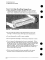
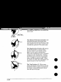
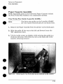
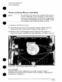
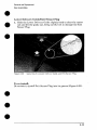
Toner Cartridge Handling Suggestions
●
Before installing a cartridge, distribute the toner evenly by
rotating the cartridge back and forth five to six times (see
Figure 2-2). Repeat this action when toner begins to run low.
Figure 2-2
Distributing Toner
●
Do not touch the sutiace of the photosensitive drum in the
cartridge. Protect the drum from light and contamination.
●
Do not disassemble
●
Do not expose the cartridge to unnecessary
●
Do not expose the photosensitive drum to strong light. White
areas on the page may indicate that the drum has been exposed
to light for too long. If white areas appear, stop the printer and
wait a few minutes. This process should eliminate most
defective images, If not, the toner cartridge maybe placed in a
dark environment for an extended period of time, which may
restore some life to the drum.
●
2-6
●
or refill a toner cartridge,
vibrations
or shock.
Never manually rotate the drum, especially in the reverse
direction; internal damage and toner spills may result.
●
●
Operating Requirements
The W 92274.4 Toner Cartridge
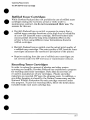
Refilled Toner Cartridges
While Hewlett-Packard
does not prohibit the use of refilled toner
cartridges during the warranty period or while under a
maintenance contract, we do not recommend their use. The
reasons for this are:
Hewlett-Packard has no control or process to ensure that a
refilled toner cartridge functions at the high level of reliability
of a new HP LaserJet toner cartridge. Hewlett-Packard
also
cannot predict what the long term reliability effect on the
printer is from using different toner formulations found in
refilled cartridges.
Hewlett-Packard has no control over the actual print quality of
a refilled toner cartridge. The print quality of HP LaserJet toner
cartridges influences the customer’s perception of the printer.
Re~airs resultimz from the use of refilled toner cartridges are
no{ covered und& the HP warranty or maintenance contract.
Recycling
Toner Cartridges
In order to reduce the amount of plastics and other wastes
entering our landfllls, Hewlett-Packard has established a program
for recycling used toner cartridges. Parts that do not wear are
re-used in manufacture of new cartridges. Plastic and other
materials are recycled. HP pays the shipping costs. In addition, a
one dollar donation is shared by the Nature Conservancy and the
National Wildlife Federation for each cartridge returned under
this program. To join this recycling effort, follow the instructions
included inside each toner cartridge box.
2-7
Operating Requirements
Media Specifications
Media Specifications
Several types of print media can be used with HP LaserJet
printers, provided the media specifications are met, Using media
that does not meet the specifications listed in this section may
increase the incidence of paper jams, cause premature printer
wear, and contribute to repair costs.
Note
More detailed media specifications are available
in the HP LaserJet Printer Family Paper
Specification Guide, part number 5002-1801. To
order additional copies, refer to “Ordering
Related Documentation” in Chapter 1.
It is possible that print media can meet all of the general
specifications listed and still not print satisfactorily because of the
printing environment or other variables over which
Hewlett-Packard has no control.
Hewlett-Packard neither warrants nor recommends the use of any
particular media brand. Properties are subject to change by
manufacturers and HP has no control over such changes. The
operator should test particular media prior to large purchases.
All media should be stable at the 392° F / 200° C temperatures
encountered in the printer’s fusing process.
CAUTION
2-8
Use ordy media recommended for use in laser
printers. Printer damage resulting from use of
incompatible media will not be covered by HP
warranty or service agreements.
Operating Requirements
Media Specificatkms
Media Sizes Supported
The following media sizes are supported by the printer’s paper
cassette and manual feed slot.
-i-able2-3
Supported MediaS3zes
LaserJet 4P/4MP
LaserJet 4L/4ML
Sizes
Universal
Cassette
Minimum size:*
3 x 7.5 in. (76x 190 mm)
3x5in. (76x 127mm)
Letter, 8.5 x 11 in. (216x279
-1-
7
Y
mm)
Legal, 8.5 x 14 in. (216x 356 mm)
I Exec, 7.25 x 10.5 in. (184x 267 mm)
A4, 210 x 297 mm (8,27 x 11.69 in.)
Envelopes:
Com-10, 4.1 x9.5 in. (105 x241 mm)
Monarch, 3.87 x 7.5 in. (98x 191 mm)
DL, 110 x220 mm (4.3 x 8.6 in,)
C5, 162x 229 mm (6.4 x 9 in.)
x
X1X
I
X
x
x
I
X
x
+=
x
x
X1X
x
Manual
Feed
r
r
x
x
x
r
r
r
r
“ Use the “flat paper path” only (manual feed and rear outpu
2-9
Operating Requirements
Media Specifications
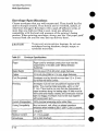
Media Selection Guidelines
To achieve the best possible print quality and avoid paper jams,
follow these guidelines for selecting paper:
Use only high quality, copier grade paper. Avoid paper with
embossed lettering, perforations, or texture that is too smooth
or too rough.
Colored paper should be of the same high quality as white
photocopy paper. The pigments must withstand the printer’s
fusing temperature of 392° F (200° C) for 0.1 second without
deterioration. Do not use paper with a colored coating that was
added after the paper was produced.
Pre-printed forms must be printed with non-flammable,
heat-resistant inks that do not melt, vaporize, or release
hazardous emissions when subject to the printer’s
approximately 392° F (200° C) fusing temperature for
0.1 second.
Always test a small sample of a new print media before
purchasing large quantities.
Give a copy of the table on the next page to your paper vendor to
ensure that the paper you purchase meets the specifications for
this printer. More detailed specifications are in the HP LaserJet
Printer Family Paper Specification Guide, HP Part No.
5002-1801. (See “Ordering Related Documentation” in
Chapter 1.)
2-1o
e
●
Operating Requirements
Media Specifications
●
●
Basis Weight
Paper Cassette: 16 to 28 pound (60 to 105 g/m2).
Manual Feed Slot: 16 to 36 pound (60 to 135 g/m2).*
Finishing Precision
Cut sheet to within 0.3 inch (0.8 mm) of nominal, 0.20°
square.
Furnish (Composition)
100% chemical wood pulp and/or cotton fiber.
Grain
Long grain.
Moisture Content
4,7 *I%
Packaging
Polylaminated
Smoothness
100 to 250 (Sheffield)*
by weight.
moisture proof ream wrap.
* LaserJet 4P/4MP only Heavier paper stock, in the range of 36 to 42 pound
(135 to 158 gid) may be used, but must use the “flat paper path” (manual
feed, rear output) and have a Sheffield smoothness rating not greater than 180.
~~~~~
The “flat paper patlf (manual feed slot and rear
face-up delivery door) is recommended for
envelopes, overhead transparencies, and labels.
2-11
Operating Requirements
Media Specifications
Envelope Specifications
Choose envelopes that are well-constructed. They should lay flat
and be sharply creased. They should not be wrinkled, nicked, or
otherwise damaged. Envelopes with a peel-off adhesive strip, or
more than one fold-over flap to seal, must use adhesives
compatible with the heat and pressure of the printer’s fusing
process. When printing envelopes, always use the “flat paper path”
~manual feed siot and the rear face-up delivery door).
To prevent severe printer damage, do not use
envelopes having windows, clasps, snaps, or
synthetic materials.
CAUTION
TaMe 2-5
Envelope
Specifications
Paper
Paper used for envelope construction must meet the
requirements in the table under “Media Selection
Guidelines.”
Basis Weight
20 to 24 pound (75 to 90 g/m2), single thickness
Caliper
3.3 to 5.5 roils (0.084 to 0.14 mm), single thickness
Curl (Pre-printed)
Envelopes must lay flat with no more than 0.2 in. (5 mm)
curl across the entire surface.
Finishing
Envelopes must not have any adhesive exposed to the
printer. They must be folded accurately, within f 0.04”
(1 mm). There must be no more than two thicknesses of
paper anywhere along the leading edge. All folds must be
well scored and sharply creased, and construction must be
tight (not baggy). Envelopes must not be stuck together
with excess seam sum.
Furnish (Composition)
1100% chemical wood pulp and/or cotton fiber.
Fusing Compatibility
Must not scorch, melt, offset, or release hazardous
emissions when heated to 392° F (20V C) for 0.1 second,
Grain
Long grain.
Moisture Content
4.7 +1% bv weiaht.
Smoothness
2-12
1100 to 250 (Sheffield)
I
I
I
Operating Requirements
Media Specifications
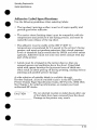
Adhesive
Label Specifications
Use the following guidelines
when selecting labels:
The top sheet (printing surface) must be of copier quality and
provide good toner adhesion.
The carrier sheet (backing sheet) must be compatible with the
temperatures and pressure of the fusing process, and must be
coated for easy release of the top sheet.
The adhesive must be stable at the 392° F (200° C)
temperatures encountered for 0.1 second in the printer’s fusing
process, and must not produce emissions that exceed exposure
levels or threshold limits established by OSHA and other safety
agencies. Adhesives must not come into direct contact with any
part of the printer.
Labels must be arranged on the carrier sheet so that any
exposed spaces run lengthwise down the sheet. Using label
stock with spaces between the horizontal rows of labels can
often result in labels peeling off during printing, causing serious
jamming and possible printer damage.
wide selection of suitable labels is available through
Hewlett-Packard.
A list of available sizes is in the H“P LaserJet
Printer Family Paper Specification Guide, HP Part No. 5002-1801.
See Chapter 1 for ordering information, or contact your local
authorized HP dealer.
CAUTION
-
Do not attempt to print on label sheets after any
of the labels have been removed from the sheet.
Damage to the printer may result.
2-13
Operating Requirements
Media Specifications
Adhesive
Must not be on any external surfaces of the label
before, during or after printing. Label construction
and die-cutting must not allow labels to peel off
during transport, printing, or fusing.
Caliper
Must not exceed 0.007 in. (0,1 9 mm)
Curl
In ream: flat within 0,2 in, (5 mm)
Finishing Precision
Cut sheet within 0.031 in. (0.79 mm) of nominal
and 0.20° square.
Fusing Compatibility
All adhesives, carrier sheets, top sheets, and other
materials used in label construction must be
compatible with the heat and pressure of the fusing
iprocess, Materials must not discolor, melt, offset,
or release hazardous emissions when heated to
392° F (20V C) for 0.1 second,
Packaging
Moisture proof wrap to preserve properties.
—
The “flat paper path” (manual feed slot and rear
face-up delivery door) is recommended for
printing adhesive labels.
2-14
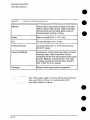
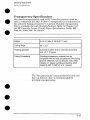
Transparency
Specifications
Overhead transparencies used in HP LaserJet printers must be
able to withstand the 392° F (200° C) temperatures encountered in
the printer’s fusing process for 0.1 second. Suitable transparency
film is available through Hewlett-Packard.
Refer to Chapter 3 of
the HP LaserJet Printer Family Paper Specification Guide, HP
Part No. 5002-1801 for details.
Caliper
13.9 to 4.3 roils (0.100 to 0.110 mm)
Cutting Angle
90° * 0.2°
Finishing precision
Cut sheet to within 0.03 in. (0.8 mm) of nominal
and t 0.2° of square.
Fusing Compatibility
Overhead transparency material must be
compatible with the heat and pressure of the fusing
process. Materials must not discolor, melt, offset
material, or release hazardous emissions when
heated to 392° F (200° C) for 0,1 second.
The “flat paper pat~ (manual feed slot and rear
face-up delivery door) is recommended for
printing transparencies.
2-15
Operating Requirements
Media Specifications
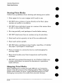
Storing Print Media
Follow these guidelines
when stacking and storing print media:
Store paper in its ream wrapper until ready to use.
DO NOT store cartons or reams directly on the floo~ place
cartons on a pallet or on shelves.
DO NOT store individual reams in a manner that causes them
to curl or warp along the edges.
Re-wrap partially used packages of media before storing.
DO NOT stack more than six cartons on top of each other.
Stack each carton squarely on top of the one underneath.
Stack each carton upright.
DO NOT place anything on top of media, regardless
the paper is packaged or unpackaged.
of whether
Store envelopes in a protective box to avoid damaging the
envelope edges.
Keep stored media away from temperature
extremes.
and humidity
DO NOT store printed documents in vinyl folders (which may
contain plasticizers) or expose the documents to petroleum
based solvents.
Shipping Print Media
When shipping print media through different environments,
plastic wrap all cartons on the shipping pallet. When shipping
media across bodies of water, wrap individual cartons as well.
Packaging must protect the media from physical damage.
2-16
Installation and
Configuration
Installation and Configuration
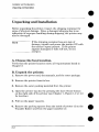
Unpacking
and Installation
Unpacking and Installation
Before unpacking the printer, inspect the shipping container for
signs of physical damage. Since a damaged shipping box is an
indication of improper handling during shipping, the printer may
also be damaged.
Note
If the shipping container has any sign of
damage, unpack and power the printer ON with
the carrier’s agent present. If the printer
appears damaged or fails self test, do not
accept it.
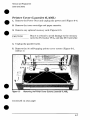
A. Choose the best location.
Verify that the printer location meets all requirements
Chapter 2.
listed in
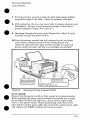
B. Unpack the printer.
1. Remove the power cord, the manuals, and the toner package.
2. Remove the printer from its box.
3. Remove the outer packing material from the printer.
4. Open the printer top door by pressing the door release button
on the right side of the printer (see Chapter 1, Figure 1-2 or 1-3
for location).
5. Pull out the paper cassette.
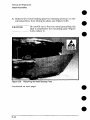
6. Remove the packing spacers from the inside of printer (2 on the
Transfer Roller) and from the paper cassette (2).
.
3-2
Installation and Configuration
Wy3acking and installation
C. Check package contents.
Nate
If any of the package contents are missing or
damaged, contact your HP dealer immediately.
The package should include the following:
● Printer.
. Power cord.
. Software Solutions package.
●
●
User’s Manual.
Toner cartridge.
Note
Interface cables are sold separately.
Chapter 8 for part numbers.
Refer to
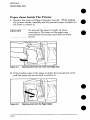
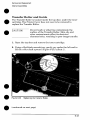
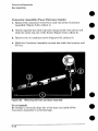
D. Install the toner cartridge.
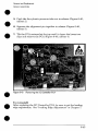
1. Press the top door release button to open its top door.
2.
Remove toner cartridge from its box and cut it open. Save the
packing materials for possible cartridge storage.
3. Shake the cartridge vigorously to distribute the toner evenly
inside the cartridge (see Figure 2-2 in Chapter 2).
4. Grasp the toner sealing tape tab on the right side of the
cartridge. Pull firmly to remove the strip of sealing tape.
5. Grasp the plastic cartridge body (not the metal shutter
linkage), and slide the cartridge into the printer, pushing it
firmly into place. Close the top door.
—
3-3
Installation and Configuration
Llnpacking
and Installation
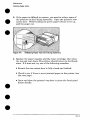
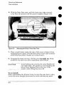
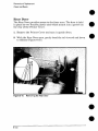
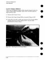
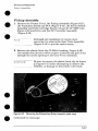
E. Load the paper cassette.
1. Pull out the paper cassette located at the lower front of printer
and load approximately 100 sheets (4L/4ML) or 250 sheets
(4P/4MP) of paper. The rear of the stack should fit loosely under
the two backstops at the rear of the paper cassette.
2. Insert the front corner of the paper stack under the metal clip
at the front of the cassette.
Note
Failure to insert the paper under the metal clip
will cause skewing or paper jams.
3. Resting the paper cassette on a flat surface, slide it into the
printer.
F. Attach the interface cable(s).
1. Open the 1/0 Door on the printer’s left rear side (LaserJet
4L/4ML only). Attach the 1/0 cable securely to the printer.
Note
Failure to attach the cable securely may result
in an 1/0 error.
2. LaserJet 41J4ML: Align the cable with the cable hole and close
the 1/0 Door.
3. Attach the I/O cable to the computer.
3-4
Installation and Configuration
LJnpwking
and hsbllattm
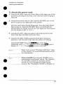
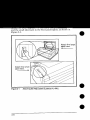
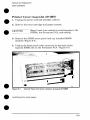
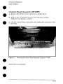
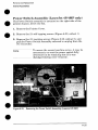
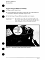
G. Attach the power cord.
1. LaserJet 4L/4ML: Open the Power Door at the right rear of the
printer by pressing on the back end of the door and swinging it
outward.
2. Connect the power cord. On the LaserJet 4P/4MP, turn on the
power switch on the right side of the printer.
All front panel lights briefly illuminate, then the green Ready
light comes on. (LaserJet 4P/4MP: There is a brief self test
period before the Ready and the On Line lights are illuminated
and the display reads %3 FZIXW.)
3. LaserJet 4L/4ML: Align the power cord with the hole at the
rear of the door and close the Power Door.
4. LaserJet 4L/4ML: Briefly press the front panel button to
generate a self test and verify that the printer is working.
LaserJet 4P/4MP: Press the key, then Menu
repeatedly until “%;;;T !%+:!..!
appears. Then press _
display SZL.F T’zx-~. Press_
to print a self test.
Id
~
U.JW
J.~
L=
~y~~
once to
Refer to the section “Printin~ a Self Test.” later
in this chapter, for a detaile~ description’ of self
test information.
Power On/OfX The LaserJet 4P/4MP uses a
conventional on/off power switch. The LaserJet
4L and 4ML printers do not have a power,
switch, but use Intelligent On/Off sensing
instead. (See “Intelligent On/Off in Chapter 5.)
3-5
Installation and Configuration
Unpacking
and installation
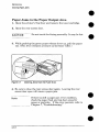
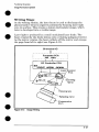
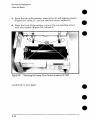
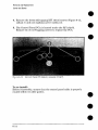
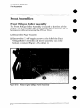
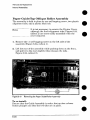
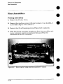
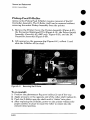
H. Attach the Help Labels (L-erJet 4~4ML onlY)
Packaged with the User’s Manual is a sheet of help labels. These
labels explain the meanings of the front control panel lights.
Attach the large help label to the inside of the printer’s top door,
and the small label next to the front panel lights, as shown in
Figure 3-1.
Figure
3-6
3-1
Attaching
the Help Labels
(LaserJet
4L/LMUW
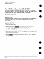
I. Install Printer Drivers and Utilities (optional)
o
●
Printer drivers are specialized programs designed to allow specific
software applications to function with the HP LaserJet printers.
Printer utilities include such things as the HP Explorer program
modules, which enhance the usability of the printer and provide
convenient access to printer features outside of specific software
applications.
How to Obtain Printer Drivers
First, check the software’s printer selection feature to see if the
printer is listed among the available printers. If it is not, run the
software’s SETUP or INSTALL program to install a “ptinter
driver” or “printer file” for the printer.
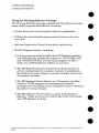
Here are some ways to obtain printer drivers and Software
Application Notes for HP LaserJet printers:
●
Check the Printing Software package to see if it includes a driver
for your software.
. Order an updated driver from the software vendor.
. Call Hewlett-Packard
at 303-353-7650.
. Obtain a driver request form by fax through HP FIRST
(call 1-800-333-1917).
. Download a driver through CompuServe’s HP Forum. To sign up
for CompuServe, call 1-800-848-8199.
,,.,.., _
J’. , .-;
a
While waiting for a specific HP LaserJet printer
driver, you can substitute a similar printer
driver (such as a driver for the HP LaserJet III,
111P, or 4 printer), These substitute drivers will
allow you to use the printer, but they do not
support all of the printer’s features.
3-7
‘
Installation and Configuration
Unpacking
and k“istallaiion
Using the Printing Software Package
The Printing Software package supplied with the printer provides
many useful programs and utilities, including:
Printer drivers for several popular software applications.
Utilities for automatically
hard disk.
Software Application
copying printer drivers onto your
Notes for the above applications.
The HP Explorer utilities, including
. A setup program which installs other HP Explorer modules
and automatically updates the computer’s AUTOEXEC.BAT
and CONFIG. SYS files. Use the setup program to add or
delete any of HP Explorer’s utilities at any time.
. The HP Explorer Remote Control Panel allows changes to
printer settings from the computer’s screen. It supplements
the software’s printer support to permit complete control over
the printer’s features.
●
The HP Explorer Status Monitor is a “Terminate-and-StayResident” (TSR) program that automatically displays
messages from the printer on the computer’s screen whenever
the printer’s status changes.
. The HP Explorer Travel Guide is a guide to the printer’s
features. It also serves as an on-line help utility when using
other HP Explorer modules.
3-8
Installation and Configuration
L/sing M Cbi’m91 FJWEd
Using the Control Panel
LaserJet 4L/4ML Control Panel Overview
The HP LaserJet 4L/4ML printer’s front control panel consists of 4
status lights and a front panel button situated on top of the printer.
A
w%.. ~
-’
jwe 3-2
Front
Panel
LaserJet4L/4MLFront
Ckmtrd
Panel
3-9
Installation and Configuration
The LaserJet 4L/4ML Lights
The LED lights provide a quick way to check the printer’s status.
Ready (Green)
STEADY: The printer is ready to print a job from the paper
cassette,
BLINKING: If this light is blinking and the Data light is on steadily,
the printer is receiving or processing data,
Data (Green)
STEADY: [f the Data light is on steadily and the Ready light is
blinking, the printer is receiving or processing data. If the Data
light and the Ready light are both on steadily, there is unprinted
data still in the printer. Briefly press the front panel button to print
the remaining data.
BLINKING: The printer is in Manual Feed mode, Either insert a
sheet of paper into the manual feed slot, or press the front panel
button briefly to print from the paper cassette instead.
Paper (Amber)
STEADY: The paper cassette is empty or missing, Add more
paper.
BLINKING: There is a paper jam. Jam locations include the paper
cassette, under the toner cartridge, or inside the printer’s rear
access door. See Chapter 4 for clearing paper jams.
Error (Amber)
STEADY: The printer’s top door is open or the toner cartridge is
either missing or not installed correctly. To correct the problem,
make sure the toner cartridge is installed completely and close the
top cover until it snaps shu~
BLINKING: The page is too complex. Press the front panel button
to continue printing. There maybe some data loss on the page.
Try setting Page Protect to On or Auto in the Printer Memory
category of the HP Explorer Remote Control panel. If the page still
doesn’t print correctly, you may need to install the optional printer
memory.
3-1o
The LaserJet 4L/4ML Front Panel Button
Depending on what state the printer is in, pressing the front panel
button allows for control of printing tasks by either starting or
resuming a printer function. Table 3-1 explains front panel button
usage.
FUNCTION I
ACTION
I
Liahts
I
RESULT
Self Test
Press button for two
seconds.
READY light on
briefly.
Continuous
Self Test
Hold down button
while powering on
printer (4L: about 5
seconds, 4ML: about
15 seconds).
All lights cycle
Prints continuous self tesi
through. Release
pages. Press the button
button when DATA to stop printing.
light only is on
(4ML: all lights on).
Reset
Press button for five
seconds or until lights
are flashing in
sequence.
Always available
except when all
lights are lit
(Service Error).
Clears all data from
memory, including
unprinted data,
downloaded fonts and
macros, Resets printer to
factory default settings.
Wake Up
F
Press button for two
seconds.
All off.
Takes the printer out of
Intelligent Off mode.
Continue
Press button for two
seconds,
Any recoverable
error code (see
Chapter 7).
Allows the printer to
recover and continue
printing the iob.
Form Feed
Press button for two
seconds,
DATA and READY
light on steady,
Print remaining data in
printer memory.
Manual
Override
Press button for two
seconds.
DATA light
blinking.
Override manual feed to
print from paper cassette.
Service
Error
Codes
Hold down button to
display code.
All lights on steady. Press the button to
display service light
pattern. Use Chapter 7 to
determine the problem
and solution.
Prints a Self Test page,
3-11
Installation and Configuration
Using the Control F%nei
LaserJet 4P/4MP Control Panel Overview
The HP LaserJet 4P/4MP printer’s front control ~anel consists of a
16 character backlit LCD display, an 8 key contr;l panel, and 4
LED status lights situated on top of the printer.
To access a primary key function (such as On Line, Form Feed, or
Menu) just press the appropriate key. To access secondary key
functions (Reset, EconoMode and -), use the_
key. For
example, to access the “reset” function of the ~
key,
press _
and ~
simultaneously.
igure 3-3
3-12
LaserJet 41Y4MP Front Control
Panel
Installation and Configuration
using it%?Cmml
Panel
LaserJet 4P/4MP Control Panel Display and Lights
The printer’s control panel has a 16 character backlit LCD
message display area and four LED status indicator lights. A
complete list of display panel messages is in Chapter 7. The
following describes the functions of the four lights.
Ready Light
ON STEADY: There are no error conditions detected. The printer
can only receive a print job when this light as well as the On Line
light are on.
BLINKING: The printer is receiving or processing data. Do not
take off line or switch power off until the light stops blinking.
OFF: The printer is not ready to print. Check the display panel for
a message.
On Line Light
E
On
fine
ON STEADY: The printer is ready to receive and process data,
BLINKING: The printer is transitioning from the On Line to Off Line
status.
OFF: The printer is off line (not ready to receive data). Other
control panel keys can now be accessed.
Form Feed Light
l==+
w
I I
ON STEADY: There is unprinted data still in the print buffer.
Press to take the printer off line, then press
~
to print the remaining data,
BLINKING: Buffered data is being printed,
OFF: No buffered data is in the printer.
EconoMode
Light
item
n
I
Ecw@70dc
Ir
ON STEADY: EconoMode is on. This reduces the amount of
toner used on the page. NOTE: Software can override this
selection, even while the EconoMode light is ON.
OFF: EconoMode is off. To turn EconoMode on, press to take the printer off line, then hold down_
while pressing
the EconoMode key.
3-13
Installation and Configuration
L!Sing the control
%yMe 3=4
3-14
Par%!
Lasel’w 4F/44JwMaw Map
Service Mode (LaserJet 4ML/4P/4MP)
The Service Mode should be used only by authorized
personnel. While in Service Mode, you can:
service
Print a Service Mode Self Test.
Verify and set the Page Count (the page count also is displayed
on the standard self test).
Set the Cold Reset Default. (This sets the factory default paper
size to either Letter or A4).
Set the Demo Page=True/False.
Used to remove the Demo Page
option from the self test menu.
Set the Diamostic Functions ON or OFF (for software
developers &e only).
LaserJet 4ML
Since the HP LaserJet 4ML does not have a front control panel,
Service Mode is accessible only through software (PJL commands).
See “PJL Software Commands” later in this Chapter.
LaserJet 4P/4MP
The following procedure is used to initiate the Service Mode (refer
to Figure 3-5).
1. Hold down the -,
~,
and m
keys while
powering ON the printer, until all lights are illuminated and
the Display Window is blank. (If the Display Window reads
.-.: :::c i c ., ,,.
. . .,
,,.,
.,”.
.... .....,.,., , ,..:...,.
_:, at this point, the keys were released too soon.
Repeat this step until successful.)
2. Click the ~
key, then the key. The message
,...,
,...
,..,
, ,.,.......
.
:..,
@.:.
,.,,,,.,-.
.,.,,,
,.,,.,,
~. w..u?:is displayed briefly, then the printer
-... ..
automatically begins a ;j~ ~E!...F: W:!. After several seconds,
both Control Panel Indicators turn OFF. (The printer may
display ‘~? :R%w~i.![~:.;? if it has not warmed up completely.)
After the printer has warmed up and passed the self test,
..-.-..
....L..
,......:.“’”””“’’-’KY’K
....... i,!..!
,,...... is displayed.
‘-”-””r”’”
3-15
‘
Installation and Configuration
Service
Mode
(laserJet 41fiL/4P~4NP)
To exit the Service Mode press them
key.
SERVICEMODE
1
SERVICEMENU
1
PAGES
1
D\AGNOSTICS
J
Figure 3-5
3-16
.—
Service Mode Menu Map (laserJet
4P14MP only)
Installation and Configuration
swill%
Mcwie &Sel’&?’i
4MLMFWMP)
Setting the Page Count (LaserJet 4P/4MP)
The page count is stored in the printer’s Non-Volatile Memory. If it
is necessary to replace the Formatter PCA, the page count should
be reset to the printer’s original page count to reflect the age of the
print engine. Use the following procedure to set the page count:
Before removing the old Formatter PCA, print a front panel self
test to verify the current page count of the printer, if possible.
Note
If it is not possible to print a self test, try to
verify the page count before replacing the
Formatter PCA by following steps 3 through 5,
below.
After veriffing the page count from the old Formatter
it with the new PCA as described in Chapter 6.
PCA, replace
1. Enter the Service Mode as described in this section.
I[:E M[]CEis displayed, press the 2. When fi~;~:...$
the Service Menu.
key to access
key to step through the menu. ~HfiiIS=J@LKYX
3. Press the m
is displayed.( ~
represents the page count currently
stored in the printer’s Non-Volatile Memory. The underlined
character denotes the cursor position. )
4. Press the m
digit.
5. Press the m
6. Press -
key to scroll the cursor to underline
key to select the correct value.
to store the new value in NVRAM.
7. Set each digit in the same manner. Press -to
display to :%%~ICE WXE.
8. Press _
the desired
return the
a second time to exit Service Mode.
—
Q
17
Installation and Configuration
service Mode (Laserdet 4MLMPMMP)
Setting the Cold Reset Default (LaserJet 4P/4MP)
The default paper size for Formatter PCAS in Europe is A4. When
replacing Formatters whose default is set for A4, set the
Customization Variable to A4. When the Customization Variable is
set to A4, the Cold Reset procedure will always reset the paper size
to A4 (not to Letter).
To set the Customization
Variable:
1. Enter the Service Mode as described in this section.
2.
Press the -
key to access the Service Menu.
3. Press the ~
key to step through the menu until
;-.:;,7~~,
.r:,-,
r:_m
-iL,.
.:-,-.
,,,IS
. displayed.
,-,
,-.,
..l,.
L
, -:-C;C>
, ..........
4. Press the ~
5. Press the ~
6. Press -to
7. Press -
key to toggle between Letter and A4 paper.
key to save your selection.
return the display to :=ti:..~t’ii tififii:.
a second time to exit Service Mode.
Other Service Mode Items
The other Service Menu items, z::!” 2;?!H=: and ~:I:w%:3T I>;= are
included for specialized purposes. If either item needs to be
changed from the default setting (=%...:
s;: and :H%, respectively),
the procedure is similar to that used for setting the page count or
Cold Reset default, described above.
3-18
●
●
Printing a Self Test
LaserJet 4L/4ML:
1, Make sure the Ready light is on, and all other lights are off. (If
necessary, reset the printer. )
2. Briefly press the front panel button (LaserJet 4ML, see Note
below).
3. After about 6 seconds, the Data light blinks and the self test
page starts to print (see Figure 3-6). Usually, only one page
prints. If fonts or macros have been downloaded, a second page
prints.
.!
,,, .:, :*>
LaserJet 4Mh The procedure above prints a
“demo page” only on the LaserJet 4ML. To print
PCL and PostScript configuration pages on the
LaserJet 4ML, press and hold the front panel
button down for at least 10 seconds, until the
Data light is ON and the Ready light is blinking.
Five pages will be printed (including font sample
pages).
LaserJet 4P/4MP:
to take the printer offline. The On Line light
1. Press goes off and the display reads H’ CFT%...:i?i-.
a
2. Press 3. Press m
●
repeatedly
until “T:+T !+%:..:is displayed.
to display :+KL..F
‘[::~-~.
The display panel reads {;:! ~;;i..~ ‘;>;;T’. After a
4. Press ~.
few minutes a PCL Configuration self test page is printed (see
Figure 3-7).
a
3-19
installation and Configuration
Printing a %4$ Tesi
Figure 3-6 shows a self test printout for the LaserJet 4L. It lists
al~factory default settings. “
J.
26 Scalable
Typefaces
u
ad
It
Courier
Bd It
Letter Gothic
Letter W.hi c Bd
Letter Goth]c !t
CG Times
CG llmes Bd
m
****8****
●
Courier
Courier
courier
EconoMode
CG ?hes it
CG ZWnesEd h
C’J.A
Univers tvld
Univm’s Ed
—
Un;vers Md It
Unfwers 8d M
Uuiws Md Cd
Umiwm Ed Cd
Umim MdCd,i
Utivets M Wh
Af)tlCme Ohre
Aatiaue Olive Bd
Antkwe Olive It
Albems Md
Albertus XBd
Wingdng3
rsd%l%~%c
—
b******@**
HP Explorer
3“
&
LmR.4m
W
L!3TBR
OFF
Mmmn.i
Ehhanced PCL 5
LTo
AUIO
OFF
OFF
0
1
12.0
10.0
EO!.(AN8
Bi-Tronics
*
Ii!!51
C.”rkr
RAM s;,.
POW,*
P.9gc
Cmmk
F)rmvm,
Datcmdc :
IWO
Adapt Uti
CO”tml Errors
,~~~
o
I-4
~ytc,
/
~
15520927
No
None
~
7
Figure 3-6
3-20
LaserJet 4L Self Test Page (showing default settings)
Installation and Configuration
Printing a SM Test
The LaserJet 4L Self Test Fields
●
●
1. Printer Features List. This area can be used to check for
graphics print quality.
2. Scalable Typeface List. Samples of the printer’s internal
scalable typefaces.
hl’a’”a
KVv,w
Removing
ac power returns items 3 through 12
settings (shown in Figure 3-6).
to facto~-default
3. Paper Handling.
Shows the current paper settings.
4. Print Quality Adjustment.
and Resolution Enhancement
Current settings for print density
(REt).
5. Memory Configuration. Settings for Image Adapt, Page
Protection, and Auto Continue.
6. EconoMode.
Setting of this toner-saving
7. Font Selection.
feature.
Current default printer font settings.
8. RAM size. Shows the total amount of installed printer
memory, including added optional memory. Use to verify proper
memory installation.
9. Page Count. Shows approximately how many pages have been
printed since the last power on. This value is returned to zero
whenever the printer is powered off.
10.Firmware Datecode. Shows the datecode of installed
firmware in YYYYMMDD format.
●
●
11. Image Adapt Status. Displays YES if the Image Adapt data
compression feature has been invoked since the last power on.
12. Control Errors. Shows the number of 1/0 or misprint errors
since the last power on.
3-21
Installation and Configuration
Pining
a sell Test
~
—..=——
$ERVICE MENU
PAGES
CR PAPER
SKIP DEMO
!31AGNOSTICS
Ps E vu
m, P* ,,,s
PMALIE L MENU
HI,” S.EED
#lW FI:TNS
~
~20
= lF1lER
= FALSE
= OFF
= m
= “ES
= ON
Pm ,.”fig
m.,,
.—.
..
.
..——
PRINTING MENU
COPIES
= 3
PAPER
- LETTER
::;:NTAT IO!.
: :ol POrr$it
~
FEm
JOB MENU
,MEDROT ECT
RESWJTIDM
PERSONALV
T ,“SOUT
SERIAL WI!.U
SFXIAC
P,C 1NC
mm RAW
m
POLARITY
.—-m-......—
1
PCL MEMU
can mm
FWT WBER
PITCH
SW SE7
:
:
= 10.00
= RCMAM8
. OFF
= ,fDlw
:
yJo
: $~:0
.
=
=
-
R.-232
El RIO*
96C+
nr
WNFIG MEMU
m WARN
AUID cCW
,,,
s,,,
●
<1..-.1)
~ :
= 3
●
TE$T MEW
,,,,
,,,,
Law SELF TEST
PC1 lVPE 11ST
,,,
mm
PA.f
m. .W, !, m,.,
,. —......
,$ TWf FACE L 1S1
,S DEMO PAGE
r
3-22
Installation and Configuration
Printing a Self Test
The LaserJet 4MIJ4P/4MP
o
●
Self Test Fields
The numbered items below refer to the Service Mode PCL
Configuration Self Test Page shown in Figure 3-7.
1. Menu Selections: Shows the current selections for all Service
menu and user menus in the order that they appear in the
control panel display (refer to the Menu Maps, Figures 3-4 and
3-5). Use this information to verify the various menu selections.
2. PS Menu: Appears on the LaserJet 4P only if the Adobe
PostScript SIMM is installed.
3. LocalTalk Information: LaserJet 4MP only. Lists the
cotilgured network name and node identification number.
4. EconoMode
5. Formatter
number.
Status:
Numbefi
Shows current status, ON or OFF.
Shows the Formatter
PCA’S serial
6. RAM Size: Shows how much memory is installed in the
printer. 2048 Kbytes is standard. If optional memory has been
added, a self test can be used to verify installation.
‘7. Page Count: Shows how many pages have been printed over
the life of the printer.
8. Firmware Datecode: Shows the datecode of the installed
firmware (in YYYYMMDD format).
a
m
●
Lists recognized
9. Installed Options/Personalities:
and personalities. Use to verify installation.
cartridges
10.REt Status: Shows the current Resolution Enhancement
setting, LIGHT, MEDIUM, DARK or OFF. (Default is
MEDIUM.)
11. Sample Printi Shows ripple print pattern (always in Courier).
This area is useful for checking print density and quality.
3-23
Installation and Configuration
Printing
a
Self Test
Continuous
Self Test
A continuous self test can be useful for troubleshooting
and other problems. To print a continuous self test:
LaserJet
paper path
41J41VIIA
1. Disconnect
the printer from the power source.
2. Press and hold down the front panel button while connecting
power.
3. Continue holding the button for:
4L - about five seconds; 4ML - about 15 seconds.
All lights will illuminate at once, then:
4L - each will light in sequence; 4ML - all lights stay lit.
4. Release the button. The printer conducts its internal
diagnostics routine, then prints the self test page continuously
until stopped.
5. To stop the continuous self test (and reset the printer), press
and hold the front panel button for a few seconds until all lights
begin lighting in sequence once again. (4ML - the printer can
take up to 2 minutes to clear the buffer and stop the self test.)
LaserJet
4P/4MP
to take the printer offline. The On Line light
1. Press goes off and the display reads W3 IHFFL1 NE.
2. Press 3. Press ~
repeatedly
until T!Z5T PEW-l is displayed.
until EUHT SELF
TE:ST is displayed.
a
The display panel reads W SELF TEST. After
4. Press ~.
few minutes a PGL Confirmation
self test ~a~e is minted (see
Figure 3-7). The self test-page will print m~l~ple ~opies,
continuing until the or ~
key is pressed.
3-24
Installation and Configuration
Engine Test
Engine Test
The engine test print can be used to verify that the print engine is
functioning correctly. The Formatter PCA is completely bypassed
during an engine test. This testis therefore useful for isolating
printer problems. The engine test prints a fhll page of vertical lines
down the entire printable area, and is thus also useful for checking
and adjusting re&istration.
An Engine Test can be performed on the
LaserJet 4L and 4ML with the printer covers in
place, as shown in Figure 3-8. The LaserJet 4P
and 4MP require removal of the covers and the
Formatter PCA. Refer to “Engine Test” in
Chapter 7 for the engine test procedure.
Note
—
Figure 3-8
Engine Test EWcm and Printout (LaserJet 4L shown]
3-25
Installation and Configuration
Resetting the Printer
Resetting the Printer
Resetting the printer clears the printer’s memory, including
unprinted data, downloaded fonts, and macros. It also removes
some error conditions, and resets to factory default settings. The
printer can be reset at any time, except when there is a service
error condition.
LaserJet 4L/4ML:
1. Hold the front panel button down for at least five seconds.
Release when all lights illuminate in succession from bottom to
top.
2. After the printer has finished the reset, the Ready light comes
on (if there are no printer errors).
LaserJet 4P/4MP:
The LaserJet 4P/4MP has several kinds of resets, as explained
below.
Simple Reset
A simple reset does the following:
Clears the printer’s page buffer.
Removes all temporary typefaces and macros.
Makes the current user-selected defaults “active” (making them
the default values until you change them again).
Purges the input buffer of the active 1/0 (the other I/O buffer is
not affected).
To perform a simple reset:
1. Press_
to take the printer offline. The On Line light
goes off and 2S ]H%i-Ii!~ appears on the display.
2. While holding down the ~
key, press briefly.
Then the printer returns to
3. S7 ~~s~~ appears on the display.
the on-line, 5E Z=W+ state.
3-26
Installation and Configuration
Resetting the Printer
The Menu of Resets
Additional reset options are available through the Menu of Resets.
Use the Menu of Resets option with caution. It can result in loss of
buffered page data or printer configuration data. You should only
use it when:
You wish to restore the default printer settings.
Communication between the printer and computer is
interrupted.
You are using both the serial and the ~arallel I/O .~orts. and one
of the ports ii having problems.
‘
To access the Menu of Resets:
1. Press to take the printer offline.
2. Hold down both the ~
and ~
keys for at least 10
.
seconds until ==:;:=-~=mw!appears on the display.
3. Use ❑ or H to cycle through the items.
to select your choice of resets. An asterisk *
4. Press ~
appears by the reset option.
to execute the reset.
5. Press -
The foIlowing table shows the three reset options.
Menu of Resets (LaserJet 4P/4MP)
Table 3-2
Menu
Printer
Selection
09 MENU
RESET.MENU
RESET.ACTIVE
RESET
ALL l/O
1/0
Explanation
Response
RESET
RESET=MENU restores most of the printer’s
factory default settings. It also performs a simple
reset. Items in the Config, Parallel, and Serial
Menus are not reset, RESET=MENU clears
only the active input buffer.
09 RESET
ACTIVE
09 RESET
ALL
1/0
1/0
RESET= ACTIVE 1/0 clears the input and output
buffers for the active //0 dy, and performs a
simple reset.
RESET=ALL l/O clears the input and output
buffers for both 1/0s, and performs a simple
reset.
3-27
Installation and Configuration
Resetting the Printer
The Cold Reset (LaserJet 4ML/4P/4MP)
Cold reset clears all data from the printer’s memory and sets all
the defaults back to the factory settings. (NOTE: The LaserJet 4L
is effectively “cold reset” whenever power is removed.)
To perform a cold reset:
LaserJet 4ML:
Cold Reset can be performed on the LaserJet 4ML through the HP
Explorer Utility (refer to the Software/Solutions
package for
instructions).
LaserJet
4P/4MP:
1. Turn off the printer.
2. While holding the _
key down, turn the printer on.
RESET appears briefly on the display, then
m !CDLE,
13z !<ELFTEN appears.
3. After about 30 seconds, fi~i CIFFL1 w appears on the display, and
the cold reset is complete.
4. Press to return the printer on line. MURE=o’,’appears
on the display.
3-28
a
Installation and Configuration
PJL Software Commands
PJL Software Commands
Many of the control panel functions explained in this chapter can
also be accessed through PJL software commands sent from the
host computer. For the LaserJet 4ML printer, functions such as
entering Service Mode, are accessible only through PJL
commands. (Note that Service Mode is available only on the
LaserJet 4ML, 4P and 4MP, and not on the LaserJet 4L.)
The following example shows how to use PJL commands to enter
Service Mode and perform various Service Mode configuration
tasks.
Text is CASE-sensitive in PJL; enter exactly as
shown. The Ec symbol stands for the ASCII
escape character (ESC or /027). When the PJL
code is entered, print the data file (or use the
DOS COPY command to copy it to the printer).
Note
Table 3-3
Example: PJL Service Mode Commands
PJL Command
Explanation
‘cYo-l 2345X@PJL
Start PJL job.
@PJL SET SERVICEMODE=HPBOISEIE
Enter Service Mode
@PJL SET PAGES=O
Set page count [= XXXXX]
@PJL SET CRPAPER=LETTER
Sets cold reset page size [= Letter/A4]
@PJL SET SKIPDEMO=FALSE
Skips demo/PCL type page [= true/false]
@PJL SET DIAGNOSTICS=OFF
Sets diagnostics [= OFF/ON] (for ISV use)
@PJL SET SERVICEMODE=EXIT
Exits Service Mode
@PJL DEFAULT PAPER. LETTER
Selects user paper size default
@PJL RESET
Performs PJL reset
‘cYo-l 2345X
Exits PJL mode
Ecz
Prints Self-Test page
ECE
Resets the printer.
3-29
Installation and Configuration
PJL Software Commands
3-30
4
b’
●
Maintenance
Maintenance
Service Checkpoints
Service Checkpoints
Figure 4-1
4-2
Service Checkpoints
1. Upper Fusing Assembly,
6. Front Oblique Roller.
2. Beam-to-Drum
7. Pickup Feed D-Roller.
Mirror.
3. Transfer Roller Assembly.
8, Photosensitive
4. Toner Cartridge.
9. Fusing Pressure Roller.
Drum.
5, Registration Roller.
10. Face-Up/Face-Down
Deflector.
Maintenance
Life Expectancy of Consumables
Life Expectancy of Consumables
Always inspect the components listed in Table 4-1 for wear when
servicing the printer. Replace these components as needed, based
on printer failures or wear, not strictly on usage.
Table 4-1
l-ik l%pectamy cd Consumables
DESCRIPTION
PART NO.
EST
LIFE
REMARKS
(P9S)
Toner Cartridge
(user replaceable)
92274A
When print becomes faint,
shake cartridge to distribute
remaining toner.
3000’
Transfer Roller
RF5-0596-OOOCN
100,000 May affect print quality
and /or ~a~er movement,
Pickup Feed D-Roller
RBI-3368-OOCN
100,000 Look for glazing andlor
cracks.
Pickup Assembly
RG5-0796-OOOCN
100,000 Look for glazing andlor
cracks, gear wear, sticky
solenoids, etc.
Front Oblique Roller
Assembly
RG5-0669-OOOCN
100,000 Look for glazing andior
cracks,
May affect
100,000
Fusing Assembly
100-120 V, 50/60 Hz
(exchange part no.)
RG5-0676-OOOCN
C2003-69001
220-240 V, 50 Hz
(exchange parl no.)
RG5-0677-OOOCN
C2003-69002
print quality and
/or paper movement, Look
for marks on lower pressure
roller or upper Teflon sleeve.
1
* The estimated toner cartridge life is based on Letter or A4 size paper with an
average of 5% toner coverage and a medium density setting. Toner cartridge life can
be extended further by conserving toner using the printer’s EconoMode feature.
4-3
Maintenance
Life Expectancy of Consumables
Toner Cartridge Life
The toner cartridge has been designed to simplify the replacement
of the printer’s major “consumable” parts. The toner cartridge
contains the printing mechanism and a supply of toner.
A toner cartridge will print approximately 3000 pages when using
a typical word processing application, in which text covers about
5% of the page (see Figure 4-2).
Figure 4..2
4-4
Sample 5% Rage Coverage
Maintenance
Life Expectancy of Consumables
a
●
When regularly printing pages with less coverage, such as short
memos, a toner cartridge should print over 3000 pages. However,
if routinely printing very dense print, the cartridge will not print a
full 3000 pages.
Note
For best results, always use a toner cartridge
before the expiration date stamped on the toner
cartridge box.
Saving Toner with EconoMode
Toner cartridge life can be extended dramatically by using the
EconoMode printing feature of the printer. EconoMode can be
turned on or off via the printer’s front panel (LaserJet 4P/4MP
only), through HP Explorer’s Remote Control Panel or through a
software application with the appropriate printer driver. See
Chapter 3 for information on the HP Explorer Remote Control
Panel.
Notes
EconoMode
functions in portrait orientation
Some software applications
“draft mode.”
only.
may refer to this as
Software settings always override front control
panel selections (LaserJet 4P/4MP).
o
●
●
4-5
Maintenance
Cleaning Printer (hnponents
Cleaning Printer Components
Do not use ammonia-based cleaners in or around
the printer. They will cause damage to the toner
— cartridge’s photosensitive drum.
CAUTION
Table 4-2
Cleaning
COMPONENT
Printer Components
I
CLEANING METHOD/NOTES
Outside Covers
Use a water-dampened cloth. Do not use solvents or
ammonia-based cleaners.
Inside General
Use a dry, lint free cloth. Remove all dust, spilled toner,
and paper particles.
Front Oblique Roller
Use a cloth or swab dampened with ethyl or isopropyl
alcohol.
Pickup Feed D-Roller
Use a water-dampened
lint-free cloth.
Registration Roller
Use a dry lint-free cloth,
Transfer Roller
Use a dry, lint-free cloth. DO NOT TOUCH with your
fingers.
Beam-to-Drum Mirror
Use filtered, compressed air first. If not effective, use a lintfree cloth or swab dampened with lens cleaner.
Fusing Pressure Roller
Use a cloth or swab dampened with water.
Face-up Deflector
Use a cloth or swab dampened with water.
4nti-Static Teeth
Use compressed air. Refer to Chapter 6 for removal
procedure. WARNING!:The Anti-Static Teeth are
extremely sharp. Be careful!
4-6
I
Maintenance
Cleaning Printer Components
a
Cleaning Spilled Toner
●
Defective toner cartridges can develop leaks. In addition, after a
paper jam has occurred, there may be some toner remaining on the
rollers and guides inside the printer. The pages that print
immediately after the jam may pick up this toner.
●
Clean spilled toner with a cloth dampened in cold water. Do not
touch the Transfer Roller with the damp cloth or your fingers. Do
not use a vacuum cleaner unless it is equipped with a micro-fine
particle filter.
Note
If toner gets on your clothing, use cold water to
remove it. Hot water sets toner stains into fabric.
4-7
Maintenance
Clearing Paper Jams
Clearing Paper Jams
●
—
Note
Paper jam messages (or status lights) will not
clear until the printer’s Top Door is opened, then
closed, or the front panel button (4 L/4ML) or
~
key (4P/4MP) is pressed.
@
Paper jams can be caused by a variety of factors:
●
Leaving the rear door open.
●
Filling the paper cassette too full.
●
Using paper that does not meet specifications
Specifications” in Chapter 2).
●
Removing
(see “Media
a paper cassette while a job is printing.
e Failing to place the corners of the paper stock under the front
and rear retainer clips in the paper cassette.
●
Printing a letter size job on legal paper.
Note
Remember to check for loose paper particles and
clean any spilled toner after a paper jam has
_ been cleared.
There are three areas of the printer where paper jams can occur:
●
The Paper Feed Area
@
s Inside the printer
●
4-8
Paper Output Area
●
Maintenance
Clearing Paper Jams
Paper Jams in the Paper Feed Area
1. Open the top door by pressing the door release button on the
upper right side of the printer.
2. Take out the toner cartridge. (Do not expose the toner cartridge
to light for more than a few minutes. Cover it while working on
the printer.)
3. Pull out the paper cassette.
4. If paper is in the paper feed area, pull the paper to the right to
relea”se it from the o-blique feed rorler. Then pull the paper
straight out.
CAUTION
Figure 4-3
Be careful not to get paper particles caught in
the front oblique roller. This can cause repeated
jams.
Paper Feed Area Jam
5. If Step 4 clears the jam, replace the paper cassette and the
toner cartridge, then close the top and rear doors. The printer
should return to the Ready state. If it does not, there may still
be jammed paper in the printer. Check the top and rear areas of
the printer (see the next page).
4-9
Maintenance
Clearing Paper Jams
Paper Jams Inside The Printer
1. Remove the toner cartmidge and paper cassette. While holding
the printer steady, carefully pull the jammed paper straight out
the front to remove it.
CAUTION
l-----+!
Figure 4-4
2.
- Do not pull the paper straight up when
removing it. The toner on the paper may
contaminate the printer and beam-to-drum
_ mirror.
\m\Y I
Clearing Jams from the Toner Cartridge Area
If the trailing edge of the paper is under the transparent .t cover,
pull the paper out and around to remove it.
/’
Illl!=l=mw \\dMl
Figure 4-5
4-1o
Y
Clearing Jams from the Paper Guide
a
Maintenance
Clearing Paper Jams
e
3. If the paper is difficult to remove, you need to relieve some of
the pressure in the Fusing Assembly. Open the printer’s rear
access door. While holding the green paper release lever up,
pull the paper out.
Figure 4-6
Releasing Paper from the Fusing Assembly
4. Replace the paper cassette and the toner cartridge, then close
the top and rear doors. The printer should return to the Ready
state. If it does not, try one of the following remedies:
. Ensure the rear access door is fully closed and latched.
. Check to see if there is more jammed paper in the printer (see
the next page).
●
. Open and close the printer’s top door or press the front panel
button briefly.
4-11
Maintenance
Clearing Paper Jams
Paper Jams in the Paper Output Area
1. Open the printer’s Top Door and remove the toner cartridge,
2. Open the rear access door.
CAUTION
- Do not touch the fusing assembly. It maybe hot.
3. Wile pushing the green paper release lever up, pull the paper
out. (This lever releases pressure on the fuser roller.)
Figure 4-7
4.
Clearing Jams from the Fuser Area
Be sure to close the rear access door again.
access door open will cause a paper jam.
—
Note
4-12
Leaving the rear
If there is still a paper jam error condition,
check the paper feed and top door areas for
If the error persists, refer to
paper or particles.
— Chapter 7, “Troubleshooting.”
-
J-
—
[D
0
n
Q
-.
CD
r
Ill
w
—
—
—
—
—
—
..........
—
>
D
-)
>
0
>
>
D
>
-1
D
>
.
1
1
JL
—
—
—
a
-a
●
●
Functional Overview
Functional Overview
Basic Printer Functions
Basic Printer Functions
This section of the manual presents a generalized functional
overview of the printer. It is designed ;O provide an understanding
of the processes that occur during printing. The following basic
printer functions are discussed:
●
—
DC Controller
System
Formatter System
Image Formation System
Paper Feed System
Power System
Basic Sequence of Operation
Fig-are 5-1 is a generalized
--------1
-J[
1
1
I
t
I
t
1
1
,
,
4
1
,
1
.,
T.
,“
delivery hay
. .
. .“.4
UA,v)!!w
~-.!.-+
..-
(w. husi campUer)
ma the bkdirectl onal
I
,
J:
~
;__
1
1
1/0
Mimi,
Formaner
PCA
1
,
:Ez+
--------I
I
,
1
l-l
‘-----
%ii6E-~O%ilii16ii
-----
--1
Scanner
motor
--
Ir
----
1
---,--------
-------
,
o
I
+FuserJ:
,
,
1
1
,
t
,
,
,
I
1
,------------..--
8
,
,
I
-------
Printer Functional
,
t,
,
,
,
T
t
C2ssene
PICK.UP/FEED
SYST131
--------------------------------------------------
Figure 5-1
5-2
Facadown
---------
I
--------------------: LASERISCANNER SYSTEM
1
t
,
I
1
‘
,
t
~--
-------------
block diagram of the printer:
Block Diagram
,
Functional Overview
DC Controller/Power System
●
a
DC Controller/Power System
The DC Controller PCA is responsible for coordinating all print
engine activities. The DC Controller drives the laser, coordinating
print data from the Formatter PCA with the image formation
process. The DC Controller shares machine status information
with the Formatter PCA so that proper diagnostic messages are
displayed. The DC Controller also provides both ac and dc power
supply and distribution circuitry. Figure 5-2 shows the various DC
Controller loads.
El
Font
Cartridge
(4P Only)
Fogn#er
F
Laser/Scanner
Assemb
DC Controller PCA
—
L
b
Laser
Diode
CPU
d
Sensors
and
Solenoids
P
DC Power Supply
u
Fan
Motor
I
I
1
Main Motor
i
+lTransfer Rollerl
Ir—————l
YAC
17gwe 5-2
Power
Supply
m
IX CofitrollerLoads
5-3
Functional Overview
DC Controller/Power System
In summary, the following systems and functions are controlled by
the DC Controller:
.
●
Print Engine Control
●
Laser and Scanner Drive
●
Paper Motion
. Microswitches
●
(Top Door and Engine Test)
. Motors (Main Drive, Scanner, Fan)
@ Power System
. AC Power Distribution
●
DC Power Distribution
‘
. High Voltage Power Distribution
. Overcurrent/Overvoltage
●
5-4
~nte]iigent
on/Off
Protection
(LaserJet 4L/4ML only)
Functional Overview
DC Controller/Power System
Print Engine Control
●
●
Laser and Scanner Drive
Based on information received from the Formatter. the DC
Controller sends a signal to the Laser/Scanner PCA to modulate
the laser diode ON and OFF. The modulated laser beam strikes
the surface of a rotating scarming mirror, is directed through a
focusing lens onto the Beam-to-Drum Mirror, and is then reflected
onto the photosensitive drum.
Synchronization of the process is achieved by continuous
monitoring of the beam detect signal, which is fed back to the
system from one end of the focusing lens. Refer to “Image
Formation System,” later in this chapter for more information.
Paper Motion Monitoring and Control
The DC Controller PCA controls paper motion by continuously
monitoring the various paper sensors, and coordinating the timing
with the other print processes.
For a detailed explanation of paper movement, and the interaction
of photosensors and solenoids with the paper movement process,
refer to the section “Paper Feed System,” later in this chapter.
5-5
Functional Overview
DC Controller/Power System
Top Door/Toner
Cartridge
Microswitch
(SW201)
Microswitch SW201, located on the DC Controller, is activated by
both the top door and the toner cartridge. If either the top door is
open or the toner cartridge is not installed, the switch opens and
an error is issued by the Formatter. On the LaserJet 4L/4ML, the
front panel’s Error (topmost) LED turns on steady. On the
LaserJet 4P/4MP, the display panel message I;: :x+;: D’ i+~ EPis
displayed. A toner cartridge must be present and the top door
must be closed before the printer can resume printing.
Top Door Plunger
Printer Chassis Top Rail
~)
LJ
\
*A
k-t-
Plunger
Assembly
Body
-
Transfer Roller A
DC Controller PCA
\!
-, . . .
Rracc-
4
I
Plate
\
\
/
/
Top Door Microswitch (SW201 )
Figure 5-3
5-6
\
‘switch
Actuator’
Metal Switch Arm
Top Cover/Toner Cartridge Plunger & Microswitch (cutaway view)
Functional Overview
DC Controller/Power System
Engine Test Microswitch
a
●
(SW301)
Microswitch SW301, also located on the DC Controller, is activated
manually through an access hole in the Drive Train Assembly on
the left side of the printer. This switch causes the print engine to
perform a self test diagnostic, bypassing the Formatter PCA. This
test is useful for troubleshooting printer problems because it
isolates the print engine from the Formatter. The engine test
prints a single page of vertical black lines, which can also be used
for adjusting print registration. See “Engine Test’ in Chapter 7 for
more information.
Note
The Engine Test print button can be accessed on
the LaserJet 4L/4ML by opening the 1/0 Door.
On the LaserJet 4P/4MP, the printer covers and
Formatter PCA must be removed first.
Motors
The Main
The Main
(following
Period, or
Motor (Ml) is controlled by the DC Controller PCA.
Motor rotates during the Initial Rotation period
initial power-ON), the Print period, or the Last Rotation
whenever the printer’s top door is opened and closed.
The Scanner Motor (M2) is controlled and monitored by the DC
Controller and Laser/Scanner PCAS. The Scanner Motor operates
during the Initial Rotation period and the Print period.
a
The Exhaust Fan Motor (M3) is controlled and monitored by the
DC Controller PCA. The Exhaust Fan Motor operates for
approximately 35 seconds during power-ON and Standby. It
remains on during Initial Rotation, Print, and Last Rotation
Periods.
5-7
Functional Overview
DC Controller/Power System
Power System (on DC Controller
PCA)
The ac, dc and high voltage power supply circuits are all contained
within the DC Controller PCA.
●
AC Power Distribution
The ac power circuitry, located on the DC Controller PCA, supplies
ac voltage to the DC Power Supply whenever the printer’s power
cord is connected to the ac power source. (The power switch must
be turned ON in the LaserJet 4P/4MP.) A toner cartridge must be
installed and the top door closed before voltage is supplied to the
High Voltage Power Supply or Main Motor drive circuitry.
DC Power Distribution
The DC Power Supply circuitry, located on the DC Controller PCA,
generates +5 V dc, and +12 V dc, which is used as follows:
+5 V dc:
Formatter PCA
Photosensors
DC Controller Circuitry
Laser/Scanner Assembly
+12a V dc:
(a=after switch)
High Voltage Power Supply
Main Motor
+12b V dc:
(b=before switch)
Solenoids
Laser/Scanner
Assembly
The Power System Block Diagram is illustrated
(to Fan)
in Figure 5-4.
o
Functional Overview
DC Controller/Power System
Power
supply
r ---,
I
II*1
----
Main switch
SW201
[4P/4MPOnly)
D
Fusing
Heeter
~ Fuse
(FU201)
Y
Mm,
o
f+12bV
+12V
2
NoW
power
supply
circuil
filter
. . . . . . . . . ..
Door switch
: H]gh- :
SW201
T,
+12av 1 uOlta9e\
; power ;
-k”
:
“
t ,
:.. .circul
. .. . . . . .
k+
1
I
a
Regula!or
n
Overvoltage/
Iovercurrent
detection
circuit
1
e
~ Main
: momr
dflve
; drcuit
----.-i
+12a V
o
Main
Motor
d Solanoid I
m
-----w
F---
m
morvionmg input
Figure 5.4
c1
...........
!-
Mainmotor
sub supply
oower circuii
‘ ‘up’”:
12b V=Voltage
before switch
12a V=Voltage
after switch,
K
I
+5V
‘El
VH301
Fan motor
+5!!!!
E
Formetter
PCA
~-SW
Power Supply Block Diagram
5-9
Functional Overview
DC Controller/Power System
Overcurrent/Overvoltage
Protection
The +12V dc and +5V dc power circuits each contain an
overcurrent/overvoltage
protection circuit which automatically
shuts off the output voltage when an overcurrent condition occurs
due to a short or abnormal voltage on the load side. The protection
circuit automatically resets after the input power is cycled OFF
then ON.
Fuse FU101 provides overcurrent protection for the Fusing System
circuitry. Fuse FU201 (not present on 220-240 V units) provides
protection in case of a catastrophic overcurrent condition in the DC
Controller power supply regulation circuitry.
Intelligent
ON/OFF (LaserJet 4L/4ML only)
This printer feature conserves power by shutting down all the
printer’s front panel LED status lights after a 15 minute period of
inactivity. The printer retains all printer settings and downloaded
fonts and macros while in Intelligent Off mode. The lights power
ON instantly when any of the following occur:
e A file is printed.
@ The front panel button is pressed.
. The printer’s top door is opened.
.
●
Paper is inserted into the manual feed slot.
A paper cassette is removed or installed.
Note
5-1o
–
The printer will not enter Intelligent
there is a printer error.
Off mode if
Functional Overview
DC Controller/Power System
High Voltage Power Distribution
a
a
The High Voltage Power Supply circuitry, located on the DC
Controller PCA, applies an overlap of dc and ac voltage to the
primary charging roller and the developing cylinder. This circuit
also applies a positive or negative dc voltage to the transfer
charging roller according to the instructions from the CPU on the
DC Controller PCA.
This circuit also controls the image density by changing the
primary ac voltage and the developing ac bias according to the
image density signal from the Formatter.
Figure 5-5 shows the timing of the high voltage power supply.
Power ON
(U.,? second)
7
WAIT
lNTR
ISBY!
PRINT
J
LSTR
ST8Y
PRINT s,gnal (/PRNT)
\
VERTICAL SYNC
signal (f70P)
Matn rmbr
—
i
n
~1.7t021
I
042
I
PnrnarY voltage (AC)
I
P,imar~ voltage (DC)
I
Develwing
bias (AC)
I
Developing bias (DC)
I
Im
Ill
~
1
I%H
+ I@%l
I
lll[lllllll!~llllilll
vcdtage changes
Bek3en-fxigebL9s
according
!0 the print sequence
(Iowerpositw voltagethan
roller to prevent
a
-:
Negative
m:
Print
Figure 5-5
,-071
I
~
,
The transfer
-:
I
t
Laser diode
Note:
,
—
Scanner motor
Transfer voltage
●
7
I
,
bms
bias
(negative
voltage
the damage
is appli~d
as follows:
the pr,nt bias isap,pleototfw
of the photosensmve
drum)
to the transfer
charging
(POSMW vokage is app,edtofhetrans
ferchargi”g
photosensitive
dmm sudsce to the paper)
mlerto
Wa”s[ercharging
roller for cleaning)
tm”sterttw
toner on the
High Voltage Power Timing
o
5-11
Functional Overview
Formatter System
Formatter System
The Formatter
.
PCA is responsible
for the following:
Receiving and processing ASCII data from the various printer
interfaces.
s Monitoring front panel input and relaying printer status
information (through the front panel and the hi-directional
.
Developing and coordinating
the print engine.
●
Storing font information.
●
Communicating
data placement
1/0).
and timing with
with the host computer.
. ...
~ DC Controller
.-
..
..-._.-.4L-L
‘“-”$-”---”
-----
~Host Computeri
--------. . . . . .
!
--.-,7-----
t
17+
Video
Interface
.
. . ..-
.
.
.
Formatter
Ttming
Controller
1/0 Controller
d
On Board
5-12
RAM
I
Control Panel
Interface
?
____
Figure 5-6
ROM
J
I
CPU
PCA
Formatter Block Diagram
I -.-..
,~.-.
.-... .-.-..
.......
Functional Overview
Formatter System
The Formatter PCA receives ASCII data from the Bi-Tronics
Interface and converts it into a dot image. The image orientation
(portrait or landscape) and the font type are both selected. When
the scan buffer is full, or when a Form Feed command is received,
the Formatter sends a PRINT signal to the DC Controller. The DC
Controller synchronizes the Image Formation System with the
Paper Feed System, and signals the Formatter to send the print
image data. The Formatter sends the print image data (dots) in
the form of a VIDEO signal and the printing process begins.
CPU
The Formatter PCA incorporates the following microprocessors:
● LaserJet
4L - Motorola 68000, 16 MHz.
● LaserJet
4ML - Intel 80960KA, 18.5 MHz.
. LaserJet 4P - Intel 80960SA, 16 MHz.
. LaserJet 4MP - Intel 80960KA, 18.5 MHz, 32K instruction
cache.
Read Only Memory (ROM)
Besides storing microprocessor control programs, the ROM stores
the dot patterns of internal character sets (fonts).
Random Access Memory (RAM)
The RAM stores printing and font information received from the
host system, and can also serve to temporarily store a full page of
print image data before the data is sent to the print engine (see
“Page Protect”). RAM memory capacities for each printer are
shown under “Printer Features” in Chapter 1. Note that adding
memory will not increase 1/0 buffer space or print speed.
Note
The LaserJet 4P/4MP printers support 32-bit
SIMMS (C303XA series) as well as the 36-bit
SIMMS (C206XA series) used in earlier LaserJet
family printers.
5-13
Functional Overview
Formatter System
Non-Volatile
Memory (~)
LaserJet 4L: The HP LaserJet 4L printer does not use NVRAM.
As long as the printer is connected to an ac power source,
configuration and page count information (as well as any
downloaded fonts and macros) is retained in conventional RAM.
When power is disconnected, RAM contents are lost, page count
returns to zero, and the printer returns to factory default settings.
LaserJet 4ML/4P/4MP: 256 bytes of NVRAM is used on these
printers to store 1/0 and print environment configuration
information. The contents of NVRAM are retained when the
printer’s power is turned off or disconnected.
(As in other HP
LaserJet printers, downloaded fonts and macros are saved in
conventional RAM, and are lost when power is turned off.)
Parallel Interface
The Formatter PCA receives incoming ASCII data through its
Bi-Tronics interface connector. The Bi-Tronics 1/0 provides high
speed two-way communication between the printer and the host,
allowing the user to change printer settings and monitor printer
status from the host computer. The Bi-Tronics I/O is compatible
with the Centronics parallel interface standard.
Note
— Refer to “Parallel Cable Pin Configuration”
Appendix B for parallel pin assignments.
in
High Speed (Yes/No)
The “High Speed (Yes/No)”
The default setting, “Yes”
speeds supported by most
the parallel interface runs
older PCs.
configuration item is user-selectable.
allows the I/O to run at the higher
newer PCs. If the mode is set to “No,”
at the slower, but compatible mode for
Advanced Functions (On/Off)
The “Advanced Functions (On/OffY configuration item is also
user-selectable.
The default setting, “On” allows for “Bi-tronics”
two-way parallel communications.
The “Ofi” mode disables the
Bi-tronics advanced functionality.
5-14
Functional Overview
Formatter System
Serial I/O (LaserJet 4P/4MP)
●
The LaserJet 4P/4MP printer supports RS-232 compatible
communications.
The printer uses a 9-pin D-subminiature
connector. (See Appendix B for pin-out information.)
serial
Pacing (Serial Modes of Operation)
@
The “Pacing” configuration
choices under Pacing are:
item is user-selectable.
Available
* DTIUDSR (default) - This mode, primarily implemented for
PCs, has hi-directional data flow which is paced using hardware
pacing. No XON or XOFF signals are sent.
e XON/XOFF - This mode is primarily intended for UNIX
machines which cannot perform hardware pacing yet want
hi-directional data flow. Data flow is paced using XON and
XOFF signals to indicate when the printer is ready to accept
new data from the host.
LocalTalk I/O (LaserJet 4ML/4MP)
The LaserJet 4ML/4MP printers implement the AppleTalk
networking protocol through the LocalTalk hardware. The
LocalTalk network cable (HP P/N 92215N) is connected through an
8-pin DIN connector on the printer’s I/O panel. (See Appendix B
for more cabling information.)
5-15
Functional Overview
Formatter System
Control Panel
LaserJet 4L/4ML
Status LED Lights: The Formatter uses four lights to communicate
printer status to the user. Light from the LEDs is transmitted
through a single piece Light Pipe Assembly, mounted on the inside
of the printer cover. Refer to “Using the Control Panel,” in Chapter 3,
and to “Printer Error Troubleshooting” in Chapter 7, for more
information on the lights.
Front Panel Button: The Formatter PCA includes a microswitch
which is activated by the front panel button through a switch
actuator which mounts on the surface of the PCA. The single
button is used for such functions as self test, reset and displaying
error codes. Refer to “Using the Control Panel,” in Chapter 3 for
more information on the front panel button.
LaserJet 4P/4MP
The Formatter PCA on the LaserJet 4P/4MP sends and receives
printer status and command data via a Control Panel PCA, which
consists of an LCD display window and an 8-key keypad.
LCD Display Window: The Formatter uses a backlit 16-character
LCD display window in conjunction with three lights to
communicate printer status to the user. Display window messages
can be configured in any of several languages.
8-Key Keypad: The eight keys on the keypad are used for a variety
of functions, such as switching online/offline, configuring the
printer, initiating self tests, form feeds, or resets, and turning
EconoMode on and off. A keyboard overlay is available in any of
several different languages (see Chapter 8 for part numbers).
5-16
Functional Overview
Formatter System
Resolution
o
●
Enhancement
(REt)
The printer’s Formatter PCA contains circuitry for Resolution
Enhancement technology (REt), which modifies the standard video
dot data on its way to the DC Controller to produce “smoothed”
black-to-white boundaries. REt is user-adjustable from the front
control panel (LaserJet 4P/4MP only), from HP Explorer’s Remote
Control Panel (Print Quality Category), or from some software
applications. Available settings are Light, Medium, Dark, or Off.
The default setting is Medium.
Note
REt settings sent from software or printer
drivers override any control panel settings.
Print Density Adjustment
Adjusting print density affects the line width (boldness) of the
print image. This is accomplished by varying the developer dc
bias, which controls the amount of toner applied to the
photosensitive drum. Print Density is adjustable through HP
Explorer’s Remote Control Panel (Print Quality Category). The
range of settings is from 1 (lightest) to 5 (darkest). The default
setting is 3.
5-17
Functional Overview
Formatter System
EconoMode
The EconoMode setting uses approximately 50% less toner than
standard mode printing by reducing the dot density. EconoMode,
which can also be thought of as “draft mode,” is user selectable via
a front panel key (LaserJet 4P/4MP only), or via a PJL sequence
using HP Explorer’s Remote Control Panel, or through application
software. The default setting is Off.
Normal
__*------
●
_*.-*---@*g*
●
Medium
Density
Density
O....*--*----’”
EconoMode vs. Regular Print
—
5-18
EconoMode,
Medium
-m---e
Figure 5-7
Note
Mode,
EconoMode does not affect print speed or
— memory usage.
Functional Overview
Formatter System
Memory Management
The printers use various methods to conserve and make the most
of available memory. Several of these are explained below.
Note
LaserJet 4P/4MP: If the printer encounters
diffkulty in managing available memory, a
“Clearable Warning” message will be displayed
on the front control panel. See “Clearable
Warnings” in Chapter 7 for details.
Memory Enhancement
technology
(MEt)
HP’s Memory Enhancement technology (MEt) effectively doubles
the printer’s standard memory through a variety of font and data
compression methods. MEt also automatically compresses fonts for
desktop publishing applications.
When printing graphics, MEt analyzes each page as it is being
printed and automatically applies a variety of methods to print the
complete page at the correct resolution. Two of these methods,
Image Adapt and Page Protect, are user-selectable through HP
Explorer’s Remote Control Panel (Printer Memory Category).
Note
MEt is only available in PCL mode; it is not
functional when printing in PostScript mode.
5-19
Functional Overview
Formatter System
Image Adapt (LaserJet 4L/4ML)
Image Adapt uses a compression technique to allow printing of
full-page graphics using the printer’s base memory. The available
settings are Auto, On, and Off. The default setting is Auto.
Some data may be lost if Image Adapt is used. To see if there has
been some loss of graphic detail, print a self test page and check
the “Image Adapt Used:” line in the Printer Information section of
the page. If the printer invoked Image Adapt since the last time
the self test was printed (or the last power cycle), that line will
read “Image Adapt Used: Yes.”
Note
LaserJet 4L/4ML: The Image Adapt information
on the self test page resets every time the self
test page prints, or the printer is disconnected
from its power source.
Page Protect
A page’s complexity (rules, complex graphics or dense text) may
exceed the printer’s ability to create the page image fast enough to
keep pace with the engine’s printing process. If a page is too
complex, it may print in parts (for example, the top half of data on
one page and the bottom half on the next page). Some print data
loss is likely in these instances, and the printer’s Error light
flashes.
Page Protect allows the Formatter to create the entire page image
in memory before physically moving the paper through the printer.
This process ensures that the entire page will be printed. Page
Protect is user selectable through HP Explorer’s Remote Control
Panel (Printer Memory Category). The default setting is Auto.
5-20
Functional Overview
Formatter System
PJL Overview
Printer Job Language (PJL) is an integral part of configuration, in
addition to the standard Printer Command Language (PCL). (See
“PJL Software Commands” in Chapter 3 for more information.)
With standard Centronics cabling, PJL allows the printer to
perform functions such as:
.
Two-way communication with the host computer through a
Bi-directional Parallel connection. The printer can tell the host
such things as the control panel settings, and allow the control
panel settings to be set from the host.
●
Dynamic I/O switching (LaserJet 4ML/4P/4MP) allows the
printer to be configured with a host on each I/O. The printer can
receive data from more than one I/O simultaneously, until the
buffer is full. This can occur even when the printer is offline.
Note
●
●
The Serial and LocalTalk I/Os share the same
softare interrupt. Thus, dynamic 1/0 switching
is limited to switching between the parallel
interface and one other I/O interface selected
from serial and LocalTalk.
Context-sensitive
switching (LaserJet 4ML/4P/4MP only)
allows the printer to recognize automatically the personalities
(PostScript or PCL) of each host and configure itself to serve
that personality.
.Isolation of print environment settings from one print job
to the next. For example, if a print job is sent to the printer in
landscape mode, the subsequent print jobs print in landscape
only if they are formatted for landscape printing.
5-21
Functional
Overview
Image Formation System
Image Formation System
Laser printing requires the interaction of several different
technologies (such as electronics, optics, and electrophotographics)
to provide a printed page. Each process functions independently
and must be coordinated with all other printer processes. The
image formation process consists of six stages:
1. Cleaning
4. Developing
2. Conditioning
5. Transferring
3. Writing
6. Fusing
The toner cartridge houses the cleaning, conditioning, and
developing stages of the process. Components of the image
formation system that wear, degrade, or are consumed are built
into the replaceable cartridge. The toner cartridge contains the
photosensitive drum, primary charging roller, developing station,
toner cavity, and cleaning station. This eliminates the need for a
service call when replacement is required.
Electrostatic
latent
image
formation
. ................. ..........._..__,
~a:::mro’
block
~. . . . . . . . .
gure 5-8
5-22
block
-.
.
.
. -.
image Formation BIocK Diagram
Functional Overview
Image Formation System
Photosensitive
Drum
The photosensitive drum is the “heart” of the Image Formation
System. The special properties of this drum allow an image to be
formed on the dram’s surface and then transferred to paper. The
drum is an extruded aluminum cylinder. The outside of the
cylinder is coated with a layer of organic-photoconductive
material
(01’C) which is non-toxic. The aluminum base of the photosensitive
drum is electrically connected to ground potential (s~e Figure 5-9).
“.-,:
\
A
‘“.;..,, Photosensitive
‘;;. Layer
.::
~~~ Aluminum
...”.
Base
Figure 5-9
Photosensitive
Drum
5-23
Functional Overview
Image Formation System
Drum Sensitivity
The OPC material has properties similar to a photo-resistor. It
becomes electrically conductive when exposed to light. When the
photosensitive drum is exposed to light, the negative charges
deposited on it are conducted to the ground potential of the drum’s
base. Areas not exposed to light remain nonconductive and
maintain their negative charge.
- The printer’s toner cartridge does not include a
CAUTION
light blocking shutter. Be careful to avoid
exposing the drum to light, which can
permanently damage the drum. Protect the
cartridge whenever removing it from the printer,
preferably by inserting it into the protective bag
— from its packaging.
t
I primary
charging
I
---
----
FigUre 5-1 U
5-24
T
area
Transfer
I Scanning
exposure
1
.-.
Drum Surtace
..
Potential
~rim~
charging
Functional Overview
Image Formation System
Cleaning Stage
During the cleaning stage of the image formation process, the
drum’s surface is physically cleaned, preparing it to hold an image.
During printing, the drum is rotating constantly making several
complete rotations per printed page. Before forming the image for
a given section of print, a cleaning blade removes toner from the
previous rotation of the drum. The excess toner is stored in the
toner cartridge where it is prevented from being used in later print
jobs (see Figure 5-11).
Cleaner
container
Cleaning
blade
\
Sweeper
Figure 5-11
strip
Drum Cleaning
5-25
Functional Overview
Image Formation System
Conditioning
Stage
After the drum is physically cleaned, it must be conditioned. This
process consists of applying a uniform negative charge on the
surface of the drum with the primary charging roller, located in
the toner cartridge. The primary charging roller is coated with
conductive rubber with an ac bias applied to erase any residual
charges and maintain a constant drum surface potential. In
addition, a negative de bias is applied by the charging roller to
create a uniform negative potential on the drum’s surface. The
amount of de voltage is modified by the print density setting.
igure 5-12
Primary Charging Roller
●
5-26
Functional Overview
Image Formation System
Writing Stage
At the writing station, the laser beam is used to discharge the
photosensitive drum’s negative potential by focusing laser light
onto its surface. This creates a latent electrostatic image, which
later is developed into a visible image.
Laser light is
beam created
As the mirror
the page from
produced by
by the diode
rotates, the
left to right
a small modulated laser diode. The
shines onto a rotating polygonal mirror.
beam reflects off the mirror and sweeps
(see Figure 5-13).
Bi-tronics
1/0
$
r———————
—- ———__
_____,
I
I
Formatter PCA
I
/BD /VDO
I ——
———
— —--~
f---i
---
DC Controller
— /BD1
/VDOUT
APCSH
PCA
/SCNON
LaserlScanner
Photosensitive
FlgWre5-13
Image Writin{g
5-27
Functional
Overview
Image Formation System
A set of lenses and mirrors focuses the horizontal sweeping beam
through the laser beam access slot in the rear of the toner
cartridge, and onto the photosensitive drum. Because the beam is
sweeping the entire length of the drum and the drum is rotating,
the entire circumference of the drum can be covered. The speed of
the scanner motor (which turns the scanning mirror) and the
speed of the main motor (which turns the drum) are synchronized,
and each successive sweep of the beam is offset l/300th
(or l/600th) of an inch. The beam can be turned on and off to place
a dot of light every l/300th (or l/600th) of an inch in the horizontal
direction. This is how the printer achieves its 300x 300 dpi
(or 600 x 600 dpi) resolution.
At the beginning of each sweep (before the beam reaches the
drum), the beam is reflected off the beam detect mirror. The
momentary pulse of light is sent to the DC Controller, where it is
converted to an electrical signal used to synchronize the output of
data (VDO) for one sweep (scan line). This pulse, referred to as the
Beam Detect signal (BD), is used to diagnose problems with the
laser diode or scanner motor.
After the writing station, the drum surface has an invisible (latent)
electrostatic image. Portions of the drum not exposed to the laser
are still at the uniform negative potential (placed there by the
primary charging roller), but those portions exposed to light have
been discharged to ground, to form the latent electrostatic image.
5-28
a
●
Functional
Overview
Image Formation System
Developing
Stage
The developing station develops the latent electrostatic image into
a visible image on the drum. The developing unit consists of a
metallic cylinder that rotates around a freed magnetic core inside
the toner cavity. Toner is a powdery substance made of black
plastic resin bound to iron particles, which is attracted to the
magnetic core of the cylinder. A rubber blade “brushes” the toner
on the developing cylinder to a uniform thickness.
The toner particles obtain a negative surface charge by rubbing
against the developing cylinder which is connected to a negative dc
supply. The negatively charged toner is attracted to the discharged
(grounded) areas of the drum exposed to laser light, and repelled
from the negatively charged (non-exposed) areas. An ac potential is
applied to the developing cylinder to decrease the attraction
between the toner and the magnetic core of the cylinder, and to
increase the repelling action of toner against the areas of the drum
not exposed to laser light. This ac potential improves density and
contrast (see Figure 5-14).
!
II
~..
Ph
w
~
Developing
cylinder
7“
AC bias
DC bias
A
F,...--.”,
i-qure
-,
3-14
nnage ueveloprnenl
5-29
Functional Overview
Image Formation System
The dc bias of the developing cylinder is adjusted to change the
force of attraction between the toner and drum by changing the
print density setting (from the front panel or through software). A
change in dc bias causes either more or less toner to be attracted to
the d~um, which in turn either increases or decreases the print
density. The print density variation is approximately t 10% (see
Figure 5-15). Both the primary and developer dc bias voltages are
changed in response to the density setting.
Developing cylinder
surface potential
Drum surface
potential
f +V
-0
2
%
s
~ -v
Figure 5-15
---------------—--... --:-----------
&
----.—
--ocbias
\
Time t
-D
(exposed area)
--- /’
Drum surface
potential
(unexposed area)
Developing Potentials
a
5-30
Functional Overview
Image Formation System
Transferring
Stage
At the transferring station. the toner image on the drum’s surface
is transferred to tfie paper: A positive cha~ge applied to the back of
the paper by the transfer roller causes the negatively charged
toner on the drum’s surface to be attracted to the page.
The small radius of the drum, combined with the stiffness of the
paper causes the paper to peel away from the drum. The Static
Eliminator also helps separate the paper from the drum. The
Static Eliminator weakens the attractive forces between the
negatively charged drum surface and the positively charged paper.
Without this help, thin paper can wrap around the drum. After
separation, the paper moves to the fusing station and the drum
rotates to the cleaning and conditioning stations.
H
I
Figure 5-16
Static charga
Jf
eliminator
Tranafer charging roller
Transferring
I
Stage
5-31
Functional Overview
Image Formation System
Fusing Stage
At the fusing station, the toner is fused into the paper by heat and
pressure to produce a permanent image. The paper passes between
a ceramic heating element protected by a thin, Teflon sleeve and a
soft pressure roller. This melts the toner and presses it into the
paper.
The ceramic heating element comes up to fusing temperature very
quickly, and thus does not require any power while the printer
is on STANDBY. These are the first Hewlett-Packard LaserJet
printers to employ this “instant-on” fusing system. Other laser
printers use a halogen heating lamp and require frequent warming
to maintain a minimum standby temperature. This feature saves
power while virtually eliminating the warm-up period.
The fusing temperature is monitored by the DC Controller PCA,
using a thermistor (TH901). The DC Controller maintains a
temperature of about 180° C during print mode. If the fusing
svstem overheats (about 215° C), a relay o~ens the Dower circuit to
the fusing heater, causing a Fuser Erro~ message. if the fusing
system exceeds 240° C, the thermal fuse will open, cutting off
power to the fuser.
Fusin
‘9’’’”---!3/:::::,,,.,.,
Toner
-
./.
\Y”
T<
Pressure
Roller
F
— -.—
—
Fusing Film and Pressure
Figure 5-17
5-32
.
\
Paper
-..
Roller
,
Functional
Overview
Paper Feed System
●
Paper Feed System
The following topics are discussed in this section:
Paper Movement
Overview
Solenoids
Photosensors
Paper Out Sensor
Input Paper Sensor
Printing from the Paper Cassette
Printing from Manual Feed
Paper Jam Detection
●
5-33
Functional Overview
Paper Feed System
Paper Movement
Overview
The paper feed system picks print media automatically from the
paper cassette or accepts it from the manual feed slot and delivers
it to the image formation system at precisely the right time. The
system then feeds the media to the fusing station, and delivers the
finished nroduct
to the outmt .~osition. either the face-down
.
output tray on top of the printer, or through the face-up delivery
slot at the rear of the printer. The output path is user-selectable by
turning the paper path knob on the rear of the printer.
Figure 5-18 shows the possible paper paths and locations of the
various solenoids, photosensors and rollers.
I
OC Controller
PCA
I
YY
Paper Cassette
.—.
Figure 5-18
5-34
‘Cassette
Feed
Paper Path
.
.
.
Printer Paper Path
PSI
Input Paper Sensor
PS2
Paper Out Sensor
Input Paper Sensor (PSI ) Positions:
A = Manual Feed Sense Position
PS3
Exit Paper Sensor
B = Registration Sense Position
PS4
Whaling Paper Sensor
C = TOP Sense Position
●
●
Functional Overview
Paper Feed System
Solenoids
Table 5-1
Solenoids
No.
Description
Name
SLI
Paper Feed Solenoid
(Registration)
Located in the Pickup Roller Assembly, and
controls the registration rollers.
SL2
Pickup Solenoid
Located on the DC Controller, and controls the
Picku~ Feed D-Roller,
Photosensors
Table 5-2
Photosensors
Name
I
I
I
Description
Psl
Input Paper Sensor
Four-position photosensor. Senses manual
feed and paper at registration position.
PS2
Paper Out Sensor
Senses empty paper cassette,
PS3
Exit Paper Sensor
Senses paper exiting the fuser rollers.
PS4
Winding Paper Sensor
Senses paper in the paper feed guide area.
Paper Out Sensor (PS2)
●
The Paper Out Sensor (PS2) detects the presence of paper in the
cassette. If no paper is sensed in the cassette, the Formatter
displays the paper-out indication on the front panel (display panel
message or Paper light). The cassette must be reloaded before
printing can resume.
5-35
Functional Overview
Paper Feed System
Input Paper Sensor (PSI)
‘“”
Registration
arm
@
WAIT
(STBY)
The Input Paper Sensor, PSI, is a four
position sensor that detects paper in the
Manual Feed Sense Position, the
Registration Position, and the Top
Position. The figure to the left shows the
Manual Feed and Cassette paper paths.
The figures below show the sensor in
each of the four positions.
The Ready or Wait/Standby Position
indicates that paper has not entered the
paper path.
Input Paper
Sensor (PSI )
The Manual Feed Sense Position (A)
indicates that paper has either been
inserted into the manual feed slot or has
been picked from the paper cassette and
reached this position in the paper path.
A
The Registration Position (B) signals
the DC Controller to monitor if the
scanner motor is up to speed and the
fuser is at the correct temperature.
When both conditions are met, the paper
continues to the Top Position. If these
conditions have not been met, solenoid
SL1 is engaged to stop the registration
roller until the printer is ready. When
the printer is ready, SL1 disengages and
paper proceeds to the Top Position.
The Top Position (C). When paper
paeses through the Top Position, the DC
Controller sends a signal to synchronize
the image on the photosensitive drum
with the top of the page.
5-36
Functional
Overview
Paper Feed System
Printing from the Paper Cassette
Paper motion begins when the DC Controller PCA, after receiving
a PRINT signal, starts the Scanner Motor, the Main Motor, and
the fusing heaters. The Pickup Solenoid (SL2) is energized for 0.5
seconds, the pickup roller and the registration roller rotate and
feed a sheet of paper from the Paper Cassette to the Registration
Position, where the registration roller is stopped by solenoid SL1,
if necessary, until the Scanner and Fuser are ready. While the
registration roller is rotating, the oblique rollers are aligning the
paper’s left edge correctly to prevent skewing (see Figure 5-19).
Left side of
the main unit
~
t
..............
Paper
Figure 5-19
Oblique Roller Paper Alignment
The Formatter PCA sends the VDO signal to the print engine
within a specified amount of time after the Input Paper Sensor
(PS1) reaches the Top Position. The leading edge is now aligned,
ready to proceed under the photosensitive drum. After the paper
passes under the drum, past the Winding Sensor (PS4), and
through the fusing unit, it triggers the Exit Paper Sensor (PS3).
The paper is then fed through either the face-up delivery slot or
the face-down output rollers and to the top output tray, depending
on the position of the face-up deflectors.
5-37
Functional Overview
Paper Feed System
Manual Feed Printing
The presence of paper in the-manual feed slot is detected when the
Input Paper Sensor (PSI) reaches the Manual Feed Sense
Position. The Manual feed system’s paper motion begins when the
DC Controller PCA, after receiving a PRINT signal, starts the
Scanner Motor, the Main Motor, and the fuser heating element.
The Registration Solenoid (SL1) is OFF at this time, allowing the
registration roller to rotate. This feeds the paper from the Manual
Feed slot to the Registration Position.
a
●
The remainder of the manual feed print process is identical to the
cassette feed process, described above.
Small Media Rollers (LaserJet 4P/4MP)
The LaserJet 4P/4MP has an additional set of Small Media
Rollers, located midway between the pickup and delivery rollers
(see Figure 5-18). These rollers allow the printer to accept a
smaller minimum paper size: 3 x 5 inches (76x 127 mm).
●
5-38
Functional
Overview
Paper Feed System
Paper Jam Detection
●
a
The Input Paper Sensor (PSI), Paper Exit Sensor (PS3), and the
Winding Paper Sensor (PS4) detect when paper is moving through
the printer (see Figure 5-18 for sensor locations). If a paper jam is
detected, the DC Controller immediately stops the printing process
and causes a paper jam indication on the front panel.
A paper jam can be detected under any of the following conditions:
Power-On
Jams
Paper is present under either PS1, PS4 or PS3 at power-on.
Pickup Jams
Paper
period
Paper
period
Sense
does not reach and clear photosensor PSI within a specified
of time. For cassette feed the time period begins when the
Pickup Solenoid (SL2) is energized; for manual feed the time
begins shortly after PSI is moved into the Manual Feed
Position (position “A” under “Input Paper Sensor”).
Delay Jams
Paper does not reach or clear a specific photosensor
specified period of time.
within a
5-39
Functional Overview
Basic Sequence of Operation
—
Basic Sequence of Operation
●
Standard Printer Operation
The Formatter PCA and the DC Controller PCA share information
during printer operation. The DC Controller-to-Formatter
Connector (DC Controller J201) forms a link which operates as a
serial data bus. This allows printer status, command information,
and dot-image data to be passed between the two PCAS. The
following events take place during normal printer operation:
Table 5-3
Print Period Descriptions
PERIOD
(refer to Timing Diagram)
PURPOSE
TIMING
WAIT
From power ON (power cord
connection) to the end of Main
Motor initial rotation.
STBY
(Standby)
From the end of the WAIT or the
LST~od
until the input of
the PRNT signal from the
Formatter. Or from the end of the
LSTR period until power OFF.
IMaintain the printer in ready state,
INTR
(Initial
Rotation)
From the input of the PRNT signal
from the Formatter until the laser
diode intensity has been stabilized.
Stabilize the photosensitive drum
sensitivity in preparation for
printing. Also clean the Transfer
Roller.
Clear the drum surface potential
and clean the Transfer Roller.
I
w=====
From the end of initial rotation until
I
LSTR
[Last
Rotation)
From the primary voltage (DC)
OFF until the Main Motor stops.
If another PRNT signal is sent
from the Formatter, the printer
returns to the INTR period. If not, it
returns to the STBY period,
5-40
Form images on the
photosensitive drum based on the
/VDO signal from the Formatter
and transfer the imaue to ~a~er.
Deliver the last sheet of paper.
Also clean the Transfer Roller.
●
General Timing Diagram
●
(Unit:
LSTR
I
●
apporox.
1
second
STBY
I
1-
9.6
1041010.8
FuSi
1
I *I
pR[,contml
4
Mair
I
5
scat
I
7
Pick
I
*
CJ~~~ +
,,
lnp~
Exit
(Ps:
12
prim
13
Prirr
d
I
Pap,
(SLI
in
30.0
1-002
4 k-02
-11- “
I
I
variable
I
,
F=.14
Dev
15
Dev
16
Trar
0.71
w
1“48
5-41
6
a
●
Removal and Replacement
Removal and Replacement
Removal and Replacement Strategy
Removal and Replacement Strategy
This chapter documents removal and replacement of Field
Replaceable Units (FRUS) only. Exchange assemblies should be
sent to SMO for repair.
Unless specifically stated otherwise, these procedures apply to all
four printer models (LaserJet 4J-J4ML/4P/4MP). Replacement is
generally the reverse of removal. Occasionally, notes are included
to provide direction for diffkult or critical replacement procedures.
WARNING!
Unplug the power cord from the power outlet
before attempting to service the printer. If this
warning is not followed, severe injury may result.
Never operate or service the printer with the
protective cover removed from the
Laser/Scanner Assembly. The reflected beam,
although invisible, can damage your eyes.
CAUTION
The printer contains parts that are electrostatic
discharge (ESD) sensitive. Always service
printers at an ESD protected workstation.
To install a self-tapping screw, first turn it
counter-clockwise
to align it with the existing
thread pattern, then carefully turn clockwise to
tighten. Do not over-tighten. If a self-tapping
screw-hole becomes stripped, repair of the
screw-hole or replacement of the affected
assembly is required.
Note
6-2
Always remove the toner cartridge and the
paper cassette from the printer before removing
or replacing printer parts.
Removal and Replacement
Required Took
Required Tools
#2 Magnetized
Small flat-blade
Phillips Screwdriver
(6-inch shaft)
Screwdriver
Small Pair Needle Nose Pliers
All screws used in the printer are Phillips head screws which
require a #2 size Phillips screwdriver. Figure 6-1 shows the
difference between a Phillips and a Pozidriv screwdriver. Note
that the Phillips tip has more beveled surfaces.
A Posidriv screwdriver will damage the printer’s
screw heads. Use Phillips only.
CAUTION
Phillips
Flglm
5-’1
Posidriv
Phillipsvs. Posidriv Screwdrivers
6-3
Removal and Replacement
User Installable Assemblies
●
User Installable Assemblies
Memory Upgrade (LaserJet 4L)
The small access door on the left side of the winter
to the memory connector on the Formatter PCA.
CAUTION
allows access
Memory modules must be removed prior to
removing the Printer Cover to avoid possible
damage ;O the memory, the Formatter PCA, or
the DC Controller.
1. Open the Memory Door.
2. Pull outward on the small handle to unplug the memory
assembly and remove.
Figure 6-2
6-4
Removing the Memory Module (LaserJet 4L)
m
Removal and Replacement
User Installable Assemblies
Memory/Language
●
SIMMS (LaserJet 4P/4MP)
The SIMM slots are under an access panel on the left side of the
printer. Place the printer on a firmly supported, flat surface.
1. Push downward forcefully on top of the access panel to release
its clips from the main Printer Cover (Figure 6-3, callout 1).
●
2. Remove any SIMM modules (release side clips, tilt upward and
lift out carefully).
clAL!-l-lo N
Figure 6-3
SIMM modules must be removed prior to
removing the Printer Cover to avoid damage.
Removing the SH’JM Access Panel (LaswJet 4P/4NlP)
Tore-install:
SIMM module can be installed in any available slot. Sequence is
irrelevant. Install with the small notch toward the left. To
re-install the access panel, hold it in place and lift firmly upward
on the thumb grip (Figure 6-3, callout 2) to snap into place.
6-5
Removal and Replacement
Cover and Doors
Cover and Doors
Power, I/O and Memory Doors (LaserJet 4L/4ML)
The Power Door is located on the right side of the printer. The I/O
Door and Memory Door are on the left side (refer to Figure 1-2).
Some doors are not hinged; and are removed simply by opening.
Others (such as the Power Door) have a small hinge tab which
holds the door in place. To remove the Power Door:
1. Open the door to a 90 degree angle.
2.
Push the upper tab down slightly and tilt the door out
(Figure 6-4).
Figure 6-4
6-6
Removing the Power Access Dcmr (LaserJet 4L/4ML)
●
a
Removal and Replacement
Cover and Doors
Printer Cover (LaserJet 41J4ML)
●
●
1. Remove the Power Door and unplug the power cord (Figure 6-4).
2. Remove the toner cartridge and paper cassette.
3. Remove any optional memory card (Figure 6-2).
CAUTION
Step 3 is critical to avoid darnage to the memory
card, the Formatter PCA, and the DC Controller.
4. Unplug the parallel cable.
5. Remove the (4) self-tapping
callout 1).
Figure 6-5
(continued
printer cover screws (Figure 6-5,
Fbncwing W Prinkr flow
Screws (LaserJet 4L/4ML)
on next page)
6-7
Removal and Replacement
Coverand Doors
6. With the Rear Door open, pull the lower rear tabs outward,
away from the printer and lift upward slightly (Figure 6-6).
Figure 696
Releasing the Printer !XIwr Flew Tabs
7. Place a small object under the rear of the cover to keep it from
snapping back in place. Pull the front lower front tabs outward,
away from the printer chassis as in step 6 above.
8. Grasping the front and rear, lift the cover straight up, being
careful to not catch any other assemblies while lifting.
CAUTION
Avoid holding the cover by the more flexible left
and right sides. Be careful to avoid catching the
green Fuser Release Tab at the rear of the
printer while lifting the cover off.
Tore-install:
When reinstalling the Printer Cover, be sure the rear door is open.
Lower the cover straight downward to avoid catching any parts.
6-8
Removal and Replacement
Cover and Doors
●
Printer Cover (LaserJet 4P/4MP)
●
●
1. Unplug the power cord and interface cable(s).
2. Remove the toner cartridge and paper cassette.
CAUTION
Steps 3 and 4 are critical to avoid damage to the
SIMMS, the Formatter PCA, and cabling.
3. Remove the SIMM access panel and any installed SIMM
modules (Figure 6-3).
4. Unplug the front panel cable connector (to the right of the
topmost SIMM slot on the Formatter PCA - Figure 6-7).
m
●
F@m: &7
(continued
C.WWOI
Panel Connector bxdcm
(LaserJet 4W41W)
on next page)
6-9
Removal and Replacement
Cover and Doors
5. From the top of the printer, remove the (4) self-tapping screws
(Figure 6-8, callout 1) and one machine screw (callout 2).
6. From the front of the printer, remove the one machine screw
with star washer (Fi@re 6-8: callout 3).
(continued
6-10
on next page)
Removal and Replacement
Cover amd Doors
7. Turn the printer around so that the back edge hangs slightly
beyond the edge of the table. Open the printer’s rear door.
8. Pull outward on the two rear cover tabs to release pressure and
lift slightly. Be sure to pull outward enough to clear the ac
power receptacle (Figure 6-9, callout 1).
9. Reaching through the access hole (Figure 6-9, callout 2), pull
outward to clear the power switch.
10.Turn the m-inter around and mdl outward on the two front
cover tab; to release pressure’ while lifting (Figure 6-9,
callout 3). Once all cover tabs are free and the ac input and
power switch are clear, lift the cover straight up carefully.
Jre
6-!3
Fkwrmving W
Cover (Laserdet
4P/4MP)
Tore-install:
Ensure that the power switch is fully seated in its retaining slot.
When lowering the cover over the chassis, be careful not to snag
the parallel port bail lock (left rear), the ac power input (right
rear), or the power switch. Watch positioning of the front cover
tabs and the control panel cable. Re-connect the control panel cable
and replace any SIMM modules that were removed.
6-11
Removal and Replacement
Cover and Doors
Rear Door
The Rear Door provides access to the fuser area. The door is held
in place by two flexible plastic tabs which mount into a groove on
the rear of the Printer Cover.
1. Remove the Printer Cover and turn it upside down.
2. With the Rear Door o~en, ~entlv bend the tab inward and down
to release (Figure 6-16). ‘ =
“
Figure 6-10
6-12
Removing the Rear Door
Removal and Replacement
Cover and Doors
Control Panel (LaserJet 4P/4MP)
1. Remove the Printer Cover and turn it upside down.
2. Remove the (3) machine screws (one with star washer)
(Figure 6-11, callouts 1 and 2).
3. Lift the Control Panel Assembly
the PCA.
and unplug the connector from
I
Figure 6-11 Removing Ilw ControlPanel Assembly(LaserJc44P/4MP)
(continued
on next page)
6-13
Removal and Replacement
Cover and Doors
4. Remove the three self tapping RFI shield screws (Figure 6-12,
callout 1) and one machine screw (callout 2).
5. The Control Panel PCA is located under the RFI shield.
F%@%6-”!2 Cmin’ii’cll
R3nd w=!SMeld (!-asErJ’e’iWV4WT)
To re-instalk
Before reassembly, ensure that the control panel cable is properly
routed within its cable guides.
6-14
Removal and Replacement
M
Side Assemblies
Left Side Assemblies
Formatter
Shield and PCA
The Formatter PCA is located under a metal RFI shield on the left
side of the printer.
PAl
UT Bf3?J
$4 Fiuniwzv
Use mo~er ESD m-ecautions when removing the
For&at~er PCA. Avoid touching component; and
use an anti-static bag for storage or ~hipping.
1. Remove the Printer Cover.
2. Remove the screws that hold the RFI shield in place and lift the
shield off (Figure 6-13, callout 1 for LaserJet 4L).
3. Remove any remaining screws on the Formatter
6-13, callout 2 for LaserJet 4L).
Figure6.13
PCA (Figure
Removing the Fcwnatler Shield and K’%A(Laserkt M shown)
6-15
Removal and Replacement
Left Side Assemblies
4. Grasp the Formatter PCA near the center and. pull straight out
(the PCA is plugged into the DC Controller through the
connector in the lower center area).
h[nf@
When replacing the Formatter PCA, remove and
transfer the Formatter to DC Controller
Connector Extension (all printers) and the
Switch Actuator (LaserJet 4L/4ML) to the new
. PCA. Procedures are shown below.
5. To remove the connector extension, squeeze the tabs on either
side and pull the Extension straight out the rear of the PCA
(Figure 6-14, callout 1).
6. LaserJet 4L /4ML: Saueeze the tabs on the Switch Actuator and
6-16
Removal and Replacement
Left Side Assemblies
Gear Train Assembly
The Gear Train Assembly is located on the left side of the printer,
under the Formatter PCA. The steps and pictures here are for the
LaserJet 4L/4ML. The LaserJet 4P/4MP is slightly larger but very
similar.
1. Remove the Printer Cover and Formatter
PCA (Figure 6-13).
2. Loosen (do not remove) the (2) upper self-tapping
screws (Figure 6-15, callout 1),
Main Motor
3. Through the access holes (Figure 6-15, callout 2), remove the (2)
screws securing the Gear Train grounding springs (small
diameter machine screws with captive star washers). These
screws are connected to the DC Controller Assembly.
4. Remove the (6) self-tapping
screws (Figure 6-15, callout 3).
5. Pull the Gear Train Assembly straight out to remove. Keep the
gear side of the assembly face up (g=ars are held in place by
light pressure only and may fall off if the assembly is tilted).
Figure 6-15
(continued
Removing the Gear Train Asswnbly (bswJet
4L shcwm)
on next page)
6-17
Removal and Replacement
LeffSide Assemblies
To re-instalh
1. Maneuver the assembly back in place, rotating some of the
gears slightly to mesh, if necessary.
2. Tighten the screws beginning
outward (Figure 6-16).
,0
in the center and working
a
CA!JTION
Do not tighten the upper two Main Motor screws
until the Main Motor and Gear Train are both in
place. Tightening the screws without the Main
. Motor in place can damage the mount.
P
Figure 6-16
6-18
!
Screw Tightening Sequence Example (Lase\rJe’i 4P shown)
●
Removal and Replacement
Left Side Assemblies
Main Motor
a
●
1. Remove the Printer Cover, and the Formatter
(Figure 6-17).
Shield and PCA
2. Remove the (1) machine screw through the access hole on the
Gear Train Assembly, approximately two (2) inches below the
top of the Main Motor (Figure 6-17, callout 1).
3. Remove the (2) self-tapping screws at the top of the Main Motor
and pull the Main Mo{& s~raight up and out (Figure 6-17,
callout 2).
6-19
Removal and Replacement
Front Assemblies
Front Assemblies
Front Oblique Roller Assembly
The Front Oblique Roller Assembly is located on the front of the
printer, and is accessible after removing the Paper Cassette. It can
be removed without removing the Printer Cover.
1. Remove the Paper Cassette.
2. Remove the (1) self-tapping screw on the left of the Front
Oblique Roller Assembly and tilt the assembly out at the
bottom to remove (Figure 6-18, callout 1).
Figure 6-l El
6-20
Removing the Oblique Roller Assembly
Removal and Replacement
Front Assemblies
Paper Cassette Assembly
Field replaceable parts on the Universal Paper Cassette include:
the Tray Forms Size Guide(s), two compression springs.
Tray Forms Size Guide (LaserJet 41J4ML)
Note
The forms size guides on the LaserJet 4P/4MP
are very easily removed and are not shown here.
1. Remove the Paper Cassette from the printer and unload paper.
2.
Slide the guide all the way to the left and forward (near the
“B5” adjustment line).
3. Lift the inside corner up slightly while twisting the guide in a
clockwise direction. This frees the tab on the back side of the
cassette, allowing removal.
Figure 6-19
Rwmvkj theTray Forms Size Guide (LaserJet 4L/4ML shown)
6-21
Removal and Replacement
Front Assemblies
Compression Springs
The Paper Cassette compression springs are located under the
large pressure plate. The LaserJet 4L/4ML is shown here.
Removal procedures for the LaserJet 4P/4MP are very similar.
a
1. Remove the Paper Cassette from the printer and unload paper.
2.
Release the plastic latch on the lower left corner of the cassette
assembly (Figure 6-20). Rotate the metal bar up and out of the
way.
3. Release the large pressure plate from the catches on both sides
(LaserJet 4L/4ML only). Raise the plate all the way up to
access the compression springs.
Tore-install:
Before lowering the pressure plate back into place, be sure that the
larger compression spring on the left side will be seated properly
on the underside of the plate.
6-22
a
●
●
Removal and Replacement
Internal Assemblies
Internal Assemblies
Laser/Scanner
Assembly
1. Remove the Printer Cover.
2. Lift the foam cover and unplug the Fan connector (Figure 6-21,
callout 1). (The Fan’s power is via the Laser/Scanner Assembly.)
3. Remove the (3) self-tapping
Note
screws (Figure 6-21, callout 2).
The uppermost screw in Figure 6-21, callout 2, is
under a protective light shutter, Do not remove
the scanner cover screw (crossed circle in Figure
6-21). There are no field replaceable parts inside
the Laser/Scanner Assembly.
4. Lift the Laser/Scanner Assembly at both ends to remove (there
may be some connection resistance - Figure 6-21, callout 3).
Figure 6-21
Removing the Laser/Scanner
Assembly
6-23
Removal and Replacement
Internal Assemblies
Fan
1. Remove the Printer Cover.
2. Lift the foam cover and unplug the Fan connector from the
Laser/Scanner Assembly (Figure 6-21, callout l).
3. Pull down on both sides of the plastic bottom tab (use a
flat-blade screwdriver on the LaserJet 4P/4MP) and tilt the
bottom of the fan outward (Figure 6-22, callout 1).
4. With the bottom tab released, pull upward on the top tab to
6-24
Removal and Replacement
Internal !ksemblies
Power Switch Assembly
(LaserJet 4P/4MP only)
The Power Switch assembly is mounted on the right side of the
printer chassis, below the fan.
1. Remove the Printer Cover.
2. Remove the (3) self tapping screws (Figure 6-23, callout 1).
3. Remove the (2) machine screws (Figare 6-23, callout 2), and
pull the Power Switch Assembly outward to unplug from the
DC Controller.
To access
necessary
downward
dislodged
the second machine screw, it maybe
to re-seat the power switch fully
in its retaining slot (if it was
during cover removal).
6-25
Removal and Replacement
Internal Assemblies
Paper Guide/Top Oblique Roller Assembly
The assembly is held in place by one self-tapping
alignment tabs, and a plastic latch tab.
Note
screw, two plastic
It is not necessary to remove the Printer Cover,
although the front alignment tabs (Figure 6-24,
callout 2) are more easily accessible with the
cover removed.
●
a
1. Remove the (1) self-tapping screw on the left side of the
assembly (Figure 6-24, callout 1).
2. Lift the rear of the assembly while pushing down at the front,
and pull it to the rear slightly (this releases the tabs Figure 6-24, callout 2).
$?jJ--J
-“
Figure 6-24
Removing the Paper Guide/Roller Assembly
Tore-install:
Ensure that the Guide Assembly is under the top door release
button plunger and that the two tabs are in place.
6-26
●
Removal and Replacement
internal Assemblies
Transfer Roller and Guide
a
●
The Transfer Roller is located inside the top door, under the toner
cartridge. The Printer Cover does not need to be removed to
replace the Transfer Roller.
CAUTION
Do not touch or otherwise contaminate the
surface of the Transfer Roller. Skin oils and
other contaminants affect its electrical
characteristics, resulting in poor image transfer.
1. Open the top door and remove the toner cartridge.
2. Using a flat-blade screwdriver, gently pry under the left end to
lift the roller shaft upward (Figure 6-25, callout 1).
Figure 6-25
●
(continued
Replacing Me Transfer Roller
on next page)
6-27
Removal and Replacement
Internal Assemblies
3. Lift the Transfer Roller and Guide slightly and slide toward the
left to remove. Do not lift the roller more than about 1 inch (2.5
cm) before sliding it out of the right bushing.
4. Pull the Roller shaft out of the clips on the Transfer Roller
Guide to release the Transfer Roller from the Guide.
—
Note
If replacing just the Transfer Roller Guide, be
careful not to lose the Transfer Roller gear. It is
only held in place by slight pressure and can fall
— off the Roller shaft.
Tore-install:
Install the right end first. Ensure that the tabs are seated firmly
in place below the plastic guide (Figure 6-25, callout 2), and push
the Transfer Roller into place.
Transfer Roller Bushings
The Transfer Roller Bushings are located under the left and right
ends of the Transfer Roller (refer to Figure 6-25). It is not
necessary to remove the Printer Cover to replace the bushings.
1. Open the top door and remove the toner carttidge.
2. Remove the Transfer Roller (Figure 6-25).
3. Remove the (1) self-tapping screw and lift the bushing straight
out (the same procedure applies for both the left and right
bushings).
6-28
Removal and Replacement
internalAssemblies
Beam-to-Drum
●
●
Nclie
Mirror Assembly
Be carefi.d not to touch the surface of the mirror
on the underside of the assembly. If the mirror
does get contaminated, use filtered, compressed
air to clean. If still dirty, clean it carefully using
lens cleaner and a lint free cloth or swab.
“
1. Remove the Printer Cover.
2. Note where the mark on the printer chassis aligns with the
graduated scale on the mirror (Figure 6-26, callout 1).
3. Remove the (2) self-tapping screws (Figure 6-26, callout 2).
Grasp the mirror assembly by the sides only, and lift to remove.
Figure 6-26
%m=mwng
‘ills Beam.to.lclrum
Mirror
Tore-install:
Install in the correct alignment as noted in step 2. Check
adjustment according to the “Beam-to-Drum Mirror Adjustment”
procedure in Chapter 7.
6-29
Removal and Replacement
Rear Assemblies
a
Rear Assemblies
Fusing Assembly
1. Remove the Printer Cover.
2. Remove the machine screws with star washers (1 on 4LJ4ML, 2
on 4P/4MP) (Figure 6-27, callout 1).
3. Remove the (2) self-tapping
4.
a
screws (Figure 6-27, callout 2).
Slide the Fusing Assembly straight out from the rear of the unit
(some resistance may be encountered because of the two
connectors to the DC Controller).
)
Figure 6-27
6-30
1
Removing the Fusing Assembly (Laser&?t 4P shown)
Removal and Replacement
Rear Assemblies
Fusing Assembly
Components
The following procedure describes the steps for disassembling the
Fusing Assembly (after it has been removed from the printer).
Please perform the steps in the sequence listed.
Pressure Plate
CAUTION
Do not remove or disturb the (2) stationary
compression springs located at either end on top
of the pressure plate. Dislocation of these
springs can cause poor fusing.
1. Remove the spring from each end of the Pressure Plate
(Figure 6-28, call&t 1).
2.
Open the Pressure Plate more than 90 degrees and lift it off its
6-31
Removal and Replacement
Rear Assemblies
Upper Fusing Assembly
(Teflon Sleeve and Heater Element)
1. Unsnap and open the cable clip shown in Figure 6-29, callout 1.
2. Remove the wires from the open cable clip and gently squeeze
the connector to unplug.
3. Unplug the second connector shown in Figure 6-29, callout 2.
4. Squeeze the tab on the ceramic heater element connector and
pull the connector free (Figure 6-29, callout 3).
5. Grip both ends of the Upper Fusing Assembly,
Figw’e 6=29
6-32
wingAssembly
Rwnoving
‘Me upper
lifting it out.
Removal and Replacement
Rear Assemblies
Pressure Roller
● ’
NOTE
●
The plastic bushings under each end of the
Pressure Roller can fall out of place and be
easily lost.
1. The Pressure Roller is now free. Grasp both ends and lift it out.
Delivery Assembly
1. Pull out gently on the metal frame on either end of the Delivery
Assembly to release the mounting pins. Lift the assembly out
(Figure 6-30).
Figure 6-30
●
●
Removing the F’user Delivery Assembly
Tore-install:
Ensure that the assembly is installed with its white plastic
pressure rollers toward the back of the Fusing Assembly,
adjacent to the Lower Delivery Rollers. It is possible to
install the Delivery Assembly backwards.
6-33
Removal and Replacement
Rear Assemblies
Lower Delivery Roller
1. Lift up on the bushing tab and slide the shaft inward and out of
the bushing (Figure 6-31, callout 1).
2. Slide the bushing out from the metal frame and slide the Lower
Delivery Roller out (Figure 6-31, callout 2).
Fic.y,mi+6-31
Removing
H-K?
ILcmwDelivery !%lkr
●
6-34
Removal and Replacement
Rear Assemblies
Lower Delivery Guide/Exit
@
Sensor Flag
1. Slide the Lower Delivery Guide slightly back to clear the center
tab and lift the guide out, being careful not to damage the Exit
Sensor Flag.
Tore-install:
Be certain to install Exit Sensor Flag into its groove (Figure 6-32).
6-35
Removal and Replacement
Rea’ Assemblies
Connector
Assembly
(Fuser Entrance
Guide)
1. Remove the connector wires from each end of the Comector
Assembly (Figure 6-33, callout 1).
o
2.
Gently squeeze the cable clip tabs using needle nose pliers and
slide the cable clip out of the frame (Figure 6-33, callout 2).
3. Remove the (1) machine screw (Figure 6-33, callout 3).
4.
Slide the Connector Assembly
lift out.
17gurr?6-33
toward the cable clip location and
Flemovhmj the Fusw Connector Assembly
Tore-install:
Be certain to correctly align the wires that run inside of the
Connector Assembly to avoid damage.
6-36
●
Removal and Replacement
Rear Assemblies
Upper Output Roller Assembly
●
1. Remove the Printer Cover.
2. Using a flat-blade screwdriver, release the two-sided tabs from
each end of the Roller Assembly (Figure 6-34).
3. Lift the Upper Output Roller Assembly
out to remove.
9
CAUTION
●
Figure 6-34
Be carefid not to lift one end of the shaft more
than about 1/2 inch (1 cm) before both ends have
been released, as this will break the shaft.
Removing the Upper Output Roller Assembly
6-37
Removal and Replacement
Rear Assemblies
Lower Output Rollers
There are four-separate output rollers located directly below the
Upper Output Roller Assembly. Each roller is held in place by
three pressure tabs.
@
1. Remove the Printer Cover.
2. Remove the Upper Output Roller Assembly
(Figure 6-34).
3. Push either the left or right tab inward, tilt the Output Roller
and lift upward to remove (Figure 6-35). Use the same
procedure for all four rollers.
Figure 6-35
6-38
Removing the Lower CMpwl Rollers
e
Removal and Replacement
Bottom Assemblies
Bottom Assemblies
DC Controller Assembly
The DC Controller Assembly is located on the bottom of the
printer. The PCA is protected by a metal shield assembly, and is
mounted to a plastic base. The Formatter PCA and Fusing
Assemblies are connected directly into the DC Controller and must
be removed prior to removal of the DC Controller Assembly.
1. Remove the Printer Cover, the Fusing Assembly (Figure 6-27),
the Formatter Shield and PCA (Figure 6-13), and the Power
Switch Assembly (LaserJet 4P14ikTP only - Figure 6-23).
Cliu-r[ah!
Failure to remove all the above components
before removing the DC Controller will result in
printer damage.
2. Remove the (2) screws that attach the grounding
Gear Train Assembly (Figure 6-36, callout 1).
springs to the
3. Remove the (5) self-tapping screws and the (1) machine screw
from the bottom of the DC Controller Assembly (Figure 6-36,
callouts 2 and 3). Do not remove the Pickup Solenoid screw
(crossed circle in Figure 6-36).
4. Push the Pickup Feed D-Roller solenoid arm in and rotate the
D-Roller down, clear of the solenoid arm (Figure 6-36, callout 4).
5. Gras~ the rails on either side of the DC Controller Assemblv
and fift the assembly out, being careful not to catch the sol&oid
arm on the Pickup Feed D-Roller.
(continued
on next page)
6-39
Removal and Replacement
Bottom Assemblies
Note
Figure 6-36
When removing the DC Controller Assembly
there will be resistance where the connectors are
attached (on the left in Figure 6-36). A firm tug
may be necessary to free the assembly.
Removing the DC Controller Assembly
To re-instalh
When reinstalling the DC Controller, be sure to use a short length
(6 mm) machine screw at Figure 6-36, callout 3. A longer (10 mm)
screw will obstruct the Fusing Assembly.
Ensure that the PSI Input Paper Sensor Arm (Figure 6-51), and
the PS2 Paper-out Sensor Flagon the D-Roller Assembly (Figure
6-41, callout 2) are in their proper positions. The Input Paper
Sensor Arm should operate freely. If either of these are not seated
properly, this will cause a continuous Paper Jam error condition.
6-40
Removal and Replacement
Bottom Assemblies
Pickup Solenoid (SL2)
●
●
The Pickup Solenoid (SL2) is located on the DC Controller PCA,
1. Remove the Fusing Assembly (Figure 6-27), the Formatter
Shield and PCA (Fiare 6-13), and Power Switch Assembly
(LaserJet 4P/4iWP &ly - Fig-&e 6-23), and the DC Contro~ler
Assembly (Figure 6-36).
2. Remove the (1) machine screw holding the Pickup Solenoid
from the lower side of the DC Controller Assembly (the crossed
circle shown in Figure 6-36).
3. Unplug the Pickup Solenoid connector (Figure 6-37, callout 1)
and remove the solenoid (Figure 6-37, callout 2).
Note
Be careful not to lose the small metal grounding
tab that fits over the solenoid’s mounting post.
6-41
Removal and Replacement
Bottom Assemblies
e
DC Controller
Fuses
There are two in-line fuses (one on 220 V units) on the component
side of the DC Controller PCA (shown in Figure 6-37, callout 3).
(The rated amperages are printed on the PCA.) Pull outward to
remove.
High Voltage Connector Assembly
This assembly is mounted on the component side of the DC
Controller PCA, and provides high voltage contact points to the
toner cartridge (shown in Figure 6-37, callout 4). To remove, press
the two tabs in on either side of the cover and lift it straight up
and off.
6-42
●
●
Removal and Replacement
Bottom Assemblies
DC Controller
PCA
If the DC Controller PCA is to be replaced, the old PCA must first
be removed from its mounting assembly.
CAUTION
The DC Controller PCA is ESD sensitive. Avoid
using conductive tools (such as metal
screwdrivers) when removing the DC Controller
PCA from its mounting assembly.
1. Remove the Fusing Assembly (Figure 6-27), the Formatter
Shield and PCA (Figure 6-13), and the Power Switch Assembly
(LaserJet 4P/4MP only- Figure 6-23).
2. Remove the DC Controller Assembly (Figure 6-36), Pickup
Solenoid, and High Voltage Connector Assembly (Figure 6-37).
3. Remove the (2) machine screws (Figure 6-38, callout 1).
Figure6-38
(continued
MachineScrew I-ocatkms(IX ControllerlWA)
on next page)
6-43
Removal and Replacement
Bottom Assemblies
4. Remove the metal backing plate by releasing pressure on the
curved portion, then tilting the plate out (Figure 6-39).
CAUTION
Figure6-39
(continued
– Be careful not to lose the metal grounding clip
that is attached to the mounting plate (Figure
— 6-40, callout 1).
Rmovhg the MkXalElackingIYak
on next page)
●
6-44
Removal and Replacement
E)ommfl AS$emblk?s
5. Push the four plastic pressure tabs out to release (Figure 6-40,
callout 2).
6. Squeeze the alignment
callout 3).
pin together to release (Figure 6-40,
7. Tilt the PCA outward at the top until it clears the lower two
Figure 6-40
Removing the IX C%ntrcdler NY!
Tore-install:
After replacing the DC Controller PCA, be sure to set the leading
edge registration.
See “Leading Edge Adjustment” in Chapter 7.
6-45
Pickup Feed D-Roller
Access to the Pickup Feed D-Roller requires removal of the DC
Controller Assembly. The D-Roller itself can be removed without
removing the entire Pickup Assembly from the printer.
1. Remove the Printer Cover, the Fusing Assembly (Figure 6-27),
the Formatter Shield and PCA (Figure 6-13), the Power Switch
Assembly (LaserJet 4P/4MP only- Figure 6-23), and the DC
Controller Assembly (Figure 6-36).
●
@
2. Lift upward on the pressure clip (Figure 6-41, callout 1) and
slide the D-Roller off the shaft. -
Tore-install:
1. Position the photosensor flag arm (callout 2) out of the way.
2. Apply pressure on the opposite end of the roller shaft (callout 3).
3. Push the D-Roller onto the shaft until it “clicks” into ~lace.
4. After replacing the D-Roller, power-on the printer wi~hout the
paper cassette in place to cause the roller to rotate into the
cotiect initial pos;tion.
6-46
●
Removal and Replacement
IEMk$m A!sse[’mks
Pickup Assembly
o
●
1. Remove the Printer Cover, the Fusing Assembly (Figure 6-27),
the Formatter Shield and PCA (Figure 6-13), the Power Switch
Assembly and Font Cartridge Bracket (LaserJet 4P14MP onlyFigure 6-23 and 6-16), and the DC Controller Assembly
(Figure 6-36).
~~:(~
Although not mandatory, it maybe more
convenient to remove the Gear Train Assembly
(Figure 6-15) to provide easier access.
-
2. Remove the plastic latch clip (D-Roller bushing, Figure 6-42).
Use needle nose pliers to twist counter clockwise and pull it out
through the access opening in the Gear Train Assembly.
[c)i~]~]cliv
Figure $-42
●
(continued
Be sure to remove the plastic latch clip as shown
in Figure 6-41 before attempting to remove the
D-Roller, or damage to the printer will result.
Removing
the Pickup Feed Roller Assembly (side view)
on next page)
6-47
Removal and Replacement
Bottom Assemblies
3. Lift upward on the pressure clip on the end of the Pickup Feed
D-Roller and remove the D-Roller (Figure 6-43, callout 1). This
provides access to one of the mounting screws.
4. Remove the (2) self-tapping screws and lift the assembly
straight out (Figure 6-43, callout 2).
Figure 6.43
Removing the Pickup Feed Roller Assembly (bottom view)
To re-instalk
Rotate the Registration Roller slightly to allow the gears to mesh
before seating the assembly.
CAUTION
6-48
Do NOT force the assembly back into place.
sure the gears are meshed properly before
replacing screws.
Be
Removal and Replacement
Bottom Assemblies
Feeder Guide Assembly
a
a
CA LJTION
●
and High Voltage Shield
1. Remove the Printer Cover, the Fusing Assembly (Figure 6-27),
the Formatter Shield and PCA (Figure 6-13), the Power Switch
Assembly (-LaserJet 4P/4&lP only- Figure 6-23), and the DC
Controller Assembly (Figure 6-36).
2. Remove the (2) self-tapping screws and the (1) machine screw
from the Feeder Guide (Figure 6-44, callouts 1 & 2).
3. LaserJet 4P14MP: Push the power switch grounding strap
outward to provide clearance (Figure 6-44, callout 3).
4. Tilt the right edge (opposite the Toner Cartridge Lever) up first,
then lift carefully up and toward the right to remove.
LaserJet 4P/4iWP: Carefully free the Small
Media Roller drive shaft before lifting upward to
avoid damage (Figure 6-44, callout 4).
Tore-install:
LaserJet 4P/4MP: Carefully align the Small Media Roller drive
shaft (Figure 6-44, callout 4) before installing the Feeder Guide.
6-49
Removal and Replacement
Bottom Assemblies
Small Media Roller Assembly
(LaserJet 4P/4MP)
1. Remove the Printer Cover, the Fusing Assembly (Figure 6-27),
the Formatter Shield and PCA (Figure 6-13), the Power Switch
Assembly (LaserJet 4P/4MP only--Figure 6-23), the DC
Controller Assembly (Figure 6-36), and the Feeder Guide
Assembly (Figure 6-44).
2. Turn the Feeder Guide black side up and remove the (1) screw
from the Small Media Roller bracket (Figure 6-45, callout 1).
Remove the bracket and drive shaft with the attached gear.
CAUTION
The drive shaft is lubricated. Be careful not to
contaminate the lubricant when handling.
3. Using a small, flat-blade screwdriver, push the (2) retaining
tabs ~ownward to release the Roller A&embly (Figure 6-451
callout 2). Slide the assembly off the Feeder Guide.
F@Jre 6-45
Removing
Me Small Media Roller Assembly
To re-instalk
Carefully align the Small Media Roller drive shaft (Figure 6-44,
callout 4) before sliding the Feeder Guide into place.
6-50
Removal and Replacement
Bottom Assemblies
Static Eliminator
The Static Eliminator
Guide Assembly.
Strip Assembly
Strip is on the under-side
of the Feeder
The metal teeth on the Static Eliminator
are very sharp and can cause injury.
vfARN!NG!
Strip
1. Remove the Printer Cover, the Fusing Assembly (Figure 6-27),
the Formatter Shield and PCA (Figure 6-13), the Power Switch
Assembly (LaserJet 4P/4MP only- Figure 6-23), the DC
Controller Assembly (Figure 6-36), and the Feeder Guide
Assembly (Figure 6-44).
2. Turn the Feeder Guide Assembly over, and slide the Static
Eliminator Strip to the right wh;le pushing the center tab out
to release (Figure 6-46, callout 1).
-. ..-
‘-
“-
m.
. .
... .
“,.
.
a.
. .
F,
.
. .
...-”
a,
.
6-51
Removal and Replacement
Bottom Assemblies
Toner Cartridge Lever Assembly
The Toner Cartridge Lever Assembly
the Feeder Guide Assembly.
is mounted on the surface of
1. Remove the Printer Cover, the Fusing Assembly (Figure 6-27),
the Formatter Shield and PCA (Figure 6-13), the Power Switch
Assembly (-LaserJet 4P/4MP only- Figure 6-23), the DC
Controller Assembly (Figure 6-36), and the Feeder Guide
Assembly (Figure 6-44),
2. Push upward on the plastic latch which holds the axis shaft in
place. Slide the axis shaft out (Figure 6-47).
3. Lift the Toner Cartridge Lever Assembly
6-47
F-icJw’e
6-52
Rei”mwincj
‘theTCmw cartridge her
out to remove.
ASsen?iiy
Removal and Replacement
BCYMNTI
Assemblies
Top Door Switch (Plunger Assembly)
●
●
1. Remove the Printer Cover, the Fusing Assembly (Figure 6-27),
the Formatter Shield and PCA (Figure 6-13), the Power Switch
Assembly (Lasenlet 4P/4MP only- Figure 6-23), the DC
Controller Assembly (Figure 6-36), and the Feeder Guide
Assembly (Figure 6-44).
2. Pry outward on the tab and slide the Top Door Switch out of the
printer (Figure 6-48).
6-53
Removal and Replacement
Bottom Assemblies
DC Controller/Scanner
Connector Assembly
1. Remove the Printer Cover, the Fusing Assembly (Figure 6-27),
the Formatter Shield and PC!A (Figure 6-13), and the Power
Switch Assembly (LaserJet 4P/4MP only- Figure 6-23).
2. Remove the Laser/Scanner Assembly (Figure 6-21), the Gear
Train Assembly (Figure 6-15), the DC Controller Assembly
(Figure 6-36), and the Feeder Guide Assembly (Figure 6-44).
3. From the left side of the minter, release messure
6-54
on the two
Removal and Replacement
Bottom Assemblies
6-55
Removal and Replacement
Bottom Assemblies
PSI Input Paper Sensor Arm
The PSI Input Paper Sensor Arm is located under the Feeder
Guide Assembly and High Voltage Shield.
1. Remove the Printer Cover, the Fusing Assembly (Figure 6-27),
the Formatter Shield and PCA (Figure 6-13), the Power Switch
Assembly (LaserJet 4P/4MP only- Figure 6-23), the DC
Controller Assembly (Figure 6-36), and the Feeder Guide
Assembly (Figure 6-44).
2. LaserJet 4L only: If necessary, remove the metal High Voltage
Shield by lifting it out.
3. Lift the Input Paper Sensor Arm out.
Figure 6-5-i
Remioving the
inputPaper.%wsw Am
To re-instalk
Be certain the Input Paper Sensor Arm and High Voltage Shield
are aligned correctly when replacing. Mis-alignment or excessive
force will break the delicate sensor arm.
6-56
Troubleshooting
Troubleshooting
Troubleshooting Flowchart
Troubleshooting Flowchart
ACPower
is
applied
tothe
printer,
When ac power is first applied to the printer:
-The exhaust fan is enabled
(4L/4ML: 35 seconds; 4P/4MP:continuous).
-The Main Motor rotates for about 5 seconds.
-Lights illuminate for about 1 second, then
4L/4ML: individually sequence front to rear,
4P/4MP: panel displays 05 SELF TEST,
then 02 WARM UP, then 00 READY.
●
o
NOTE: The fan will NOT rotate if any error
condition is present. Refer to Tables 7-1
through 7.15 to correct,
Yes
If no error or service message is being
displayed, the Top Door is closed, and the
toner cartridge is installed, yet the fan does
NOT rotate when ac power is applied to the
printer, verify the following:
1. Power at the receptacle is good.
2 The fan is fully seated into its connector at
the Scanner Assembly.
3. The Scanner is fully seated into its
connector on the DC Controller PCA.
4, FusesFU101 and FU202 on the
DC Controller are NOT open.
If no error or service message is being
displayed, the Top Door is closed, and the
toner cartridge is installed, yet the Main Motor
does NOT rotate when ac power is applied to
the printer, verify the following:
1. Motor is correctly mounted on chassis and
seated into DC Controller connector.
2. Replace the Main Motor.
3. Replace the DC Controller PCA.
(continued
onnextpage)
7-2
a
a
Troubleshooting
Troubleshooting Flowchart
If the Control Panel is not functional:
1. Verify Formatter PCA is fully seated into
the DC Controller PCA.
2. Replace the Formatter PCA.
3. Replace the DC Controller PCA.
a
Periorm
an
Engine
Test,
Refer to the section “image Formation
Troubleshooting,” later in this chapter.
[f the engine test produces a clear print
image, yet a clear Self Testis not generated
by the front panel self test procedure, replace
the Formatter PCA.
7-3
Troubleshooting
Paper Path and Components
Paper Path and Components
I
Figure 7-1
7-4
DC Controller PCA
Paper Path and Components
Input Paper Sensor (PSI ) Positions:
Psl
Input Paper Sensor
PS2
Paper Out Sensor
A = Manual Feed Sense Position
PS3
Exit Paper Sensor
B = Registration Sense Position
PS4
Winding Paper Sensor
C = TOP Sense Position
a
Troubleshooting
DC Controller Diagram
DC Controller Diagram
4
TO FRONT OF PRINTER
VR301
I
‘–
––––––f
Psl
I
I
1
–––A;P;
I
J301
–––I
Clrcultry
I
J202
[
~
FUIOI IOA (12~
m
~H
000
Figure 7-2
PS3
(PS301)
n
J103
.J-J
SW301 [
J*~~
0
DC Controller
PCA Components
J201
Formatter Connector
J404
Drum Ground
J202
Laser/Scanner
VR301
Leading Edge Adjustment
Connector
J601
Main Motor Drive
SW301 Engine Test Print Microswitch
J103
Fusing Assy (Heating Element
and Thermoprotector)
SW201 Top Door /
Toner Cartridge Microswitch
J204
Fusing Assy (Thermistor THI )
PSI
Input Paper Sensor
J206
Pickup Solenoid SL2
PS2
Paper Out Sensor
J207
Paper Feed Solenoid SL1
PS3
Exit Paper Sensor
J401
Primary Charge Roller
PS4
Winding Paper Sensor
J402
Developer Roller
FU201
DC Controller Power Supply Fuse
J403
Transfer Roller
FU1OI
Fusing System Circuitry Fuse
—,
7-5
Troubleshooting
Printer Error Troubleshooting
Printer Error !Ikoubleshooting
The printers use various means for conveying
messages, as follows:
status and error
LaserJet 41J4ML:
The HP LaserJet 4L/4ML printers are the first of the HP LaserJet
family that do not use a di;play panel interface. Information
regarding printer status is conveyed by two methods: 1) the
printer’s Control Panel lights, and 2) feedback through the
hi-directional 1/0 to display on the host computer.
●
e
The basic method of determining error messages uses patterns of
lights on the front panel LEDs. Printer messages are categorized
into two basic types: Recoverable Errors, and Service Errors.
Both types are covered in the following sections.
Note
Before troubleshooting a Service Error, cycle the
power to the printer to see if the error persists.
LaserJet 4P/4MP:
The LaserJet 4P/4MP uses an alphanumeric display panel for
conveying status and error messages. In addition, as in the
LaserJet 4L, feedback is directed through the printers
hi-directional 1/0 to display on the host computer.
●
7-6
Troubleshooting
Printer Error Troubleshooting
Priority of Errors
Each error has a priority in relation to the others. If there is more
than one error condition at the same time, the highest priority
error will be displayed. The priority of errors is:
1.
2.
3.
4.
5.
6.
Service Errors
Door Open/No Toner Cartridge
Paper Jam
Paper Out
Memory Error
Manual Feed
Recoverable
Errors
Recoverable Errors are displayed on single front panel lights
without pressing the front panel button. Recoverable errors do not
require a service call unless the error persists after the suggested
remedy has been implemented. Recoverable errors are listed in
Tables 7-1 through 7-5.
Table 7-1
Pa~er Out Error
LaserJet
4L/4ML LEDs
~
L
Paper light is
on steady. All
other lights are
off.
LaserJet 4P/4MP
Display Panel
I
Description
& Recommendations
PC LOAD [paper size] 1. Paper Cassette is empty or missing.
2, Add paper and/or insert cassette.
3. Reseat the cassette.
4, Check if Paper Out flag PS2 (bottom of
printer, adjacent to the Pickup D-Roller) is
broken or movement is hindered. Unstick
or replace the Pickup Assembly.
5. Replace DC Controller PCA.
7-7
Troubleshooting
Printer Error Troubleshooting
Table 7-2
Paper Jam Error
LaserJet
4L/4ML LEDs
+=
~+;
am
1 UH
‘aper light is
)Iinking. All
]ther lights are
)ff.
—
7-8
LaserJet 4P/4MP
Display Panel
13 PAPER JAM
Description
& Recommendations
1, Paper in printer. Remove paper by
referring to Chapter 4, Clearing Paper Jams.
2. Rear Door Open. Close door and reset
printer.
3. Jam removed but printer not reset.
Perform front panel reset.
4. Transfer Roller Guide Plate not installed
correctly (all 3 tabs must be in position),
See Chapter 6 for installation procedure.
5. Stuck or broken flags/sensors.
Note where the leading edge of the paper is
to determine which paper sensor maybe
causing the jam. Ensure sensor flags rotate
freely. Replace flags or associated
assemblies if broken or if they remain stuck.
6. Paper fragment under oblique rollers (top
or front). Remove rollers and clear out paper.
7. Main Motor faulty. Power up the printer
and observe if the stacker rollers rotate. If
not, replace the Motor.
8. Stuck or Faulty Gears in Gear Train.
Replace Gear Train.
9. Toner cartridge not rotating. Refer to
“Drum Rotation Functional Check later in
this chapter.
10. Transfer Roller Gear missing or broken.
Replace the Transfer Roller.
11. Stuck or broken solenoids. Replace
solenoid or associated assembly.
12. DC Controller PCA faulty. Replace PCA.
13. Software related: for example, program
in letter, but feeding legal size paper.
Change the software paper size setting, or.
feed the designated size.
Troubleshooting
Printer Error Troubleshooting
Table 7-3
Door Open Error
LaserJet
4L/4ML LEDs
$m
ma
~m
D o=
Error light is on
steady. All
other lights are
off.
LaserJet 4P/4MP
Display Panel
---
Figure T-3
& Recommendations
12 OPEN OR NO EP 1. Printer’s Top Door is open andior the
toner cartridge is missing or not installed
properly. Reinstall toner cartridge and close
door.
2. Part of the Top Door that pushes the
plunger down is broken. Replace the Top
Door,
3, Top Door Switch (Plunger Assembly) is
broken. Replace (see Figure 7-3).
4, Toner Cartridge Lever Assembly is
broken, Replace the Assembly,
5, Faulty Microswitch SW201 (Top Door
Switch) on the DC Controller PCA, Replace
DC Controller PCA.
Top Door Microswitch
---
Description
--
(SW201
)
Metal
..—.
Top Door/Toner cartridge
Switch
Arm
Plunger and Lever Assembly
7-9
,’
Troubleshooting
Printer Error Troubleshooting
Table 7-4
Memorv Error
LaserJet
lL/4ML LEDs
LaserJet 4P/4MP
Display Panel
Description
20 MEM OVERFLOW
21 PRINT OVERRUN
22 ERROR
1. Too much data, or data too complex.
Turn Page Protection ON or to AUTO (can
be set within HP Explorer’s Remote Control
Panel).
2. Add optional memory.
3. Reduce the complexity of the print job.
‘r’or light is
inking, and
I other lights
e off.
Table 7-5
& Recommendations
LaserJet 4P/4MP: Press ~
resume r)rintina.
to
Manual Feed
1
LaserJet
4L/4ML LEDs
Data light is
blinking, and
all other lights
are off,
7-1o
LaserJet 4P/4MP
Dis~lav
. . Panel
Description
& Recommendations
AF FEED [paper size] 1, Insert paper into the manual feed slot.
AE FEED[env. size]
This will fulfill the manual feed request.
2, To avoid manual feed on this job, press
the front panel button to override the
manual feed request and to feed paper from
the paper cassette.
3. To avoid manual feed on future jobs, go
into a software application or the HP
LaserJet Explorer to change the setting
from Manual Feed to Paper Cassette feed.
Troubleshooting
Printer Error Troubleshooting
Service Errors
ServiceErrors inhibit further operation of the printer until some
action is taken.
LaserJet
4L/4ML
All lights will turn on in a steady state. Pressing and holding the
front panel button will reveal a pattern on the lights. (The error
pattern will only be displayed as long as the front panel button is
held down.) Use this pattern and the corresponding reference in
Tables 7-6 through 7-15 to identify what type of service error has
occurred.
LaserJet
4P/4MP
Service messages are displayed on the front Control Panel in the
same manner as all other messages. No action is required to
display further error codes.
Table 7-6
Service Error
LaserJet
4L/4ML LEDs
LaserJet 4P/4MP
Display Panel
fim
Not Applicable
(LaserJet 4L14ML
Only)
El
~lca
QDI
C)m
All four lights
on (without
pressing the
front t3anel
l!wiL-
Description
& Recommendations
There is a service error. Press and hold
the front panel button to display the error
light code. This code will be shown only
while the button is pressed, The following
tables list possible error codes.
NOTE: If no further error code is displayed,
yet all four lights remain on continuously,
power cycle the printer. If the condition
persists, replace the Formatter PCA.
7-11
Troubleshooting
Printer Error Troubleshooting
Table 7-7
Fuser Error
LaserJet
4L/4ML LEDs
LaserJet 4P/4MP
Display Panel
\m
50 SERVICE
El
I
C)m
Table 7-8
& Recommendations
1. Remove power to the printer for 15
minutes. If this doesn’t clear the error:
2. Perform the Fuser Checks shown in the
table below.
3. Check the Fuses (FU101 and FU201) on
the DC Controller PCA. Replace if faulty.
3. Replace the DC Controller PCA.
ND
fg=
Ready and Error lights are on
and all others
are off.
Description
1
Fuser Checks
SUSPECT.
I
CHECK
1. Connector Contact
Ensure that J103 and J204 connectors on the Fusing
Assembly are seated securely into the DC Controller
PCA connectors (see Figure 6-29 in Chapter 6 for
locations). Reseat the Fusing Assembly,
2. Thermistor wire open.
Remove the Fuser and measure the resistance
between connectors J204-1 and J204-2 (see
Figure 6-29 in Chapter 6 for location), Resistance
should read approximately 440 K Ohms at 20 Deg C
(room temperature). If the thermistor wire is open,
replace the Fusing Assembly.
3. Thermal Fuse.
Measure the continuity between connectors JI 03-1
and J1 03-2 on the Fuser (see Figure 6-29, Chapter 6
for location). It should be approximately 29 Ohms. If
the thermal fuse is open, replace the Fusing Assembly
7-12
I
Troubleshooting
Printer Error Troubleshooting
Beam Error
Table 7-9
LaserJet
4L/4ML LEDs
;m
El
LaserJet 4P/4MP
Display
. . Panel
51 ERROR
Elm
am
UD
Data and Error
lights are on
and all others
are off.
Table ‘7-1O
I
Description
& Recommendations
Power-cycle the printer. If this doesn’t clear
the error:
1. Reseat the Laser/Scanner Assembly into
the Scanner/DC Cable Assembly.
2. Replace the Laser/Scanner Assembly.
3. Replace the DC Controller PCA,
4. Replace the Scanner/DC Cable
Assembly.
Scanner Error
LaserJet
4L/4ML LEDs
LaserJet 4P/4MP
Display Panel
52 ERROR
;:
Qm
D UE3
Paper and Error lights are on
and all others
are off.
Description
& Recommendations
Power-cycle the printer. If this doesn’t clear
the error:
1, Ensure condensation from moving the
printer from a cold to warm environment
hasn’t occurred, Allow the printer 6 hours to
acclimate to the warm room.
2. Reseat the Scanning Assembly.
3. Replace the Laser/Scanner Assembly.
4. Replace the DC Controller PCA,
5. Replace the Scanner/DC Cable
Assembly,
7-13
Troubleshooting
Printer Error Troubleshooting
—
Table 7-11
RAM/ROM Error
LaserJet
4L/4ML LEDs
LaserJet 4P/4MP
Display Panel
[XY-ZZ] ERROR
Description
& Recommendations
An error has been found in RAM or ROM.
1. Power-cycle the printer. If this doesn’t
clear the error:
2. Power off the printer, remove any
additional memory, then power back on. If
the message clears, replace the memory
card.
3. Replace the Formatter PCA.
LaserJet 4P/4MP: Use the list below to
decode the [XY-ZZ] values:
X - Hardware type:
O = ROM
1. RAM
Y- Hardware device:
O. On board RAM/ROM.
1 = SIMM slot one.
2 = SIMM slot tWO.
3 = SIMM slot three.
ZZ - Error Number:
00= Unsupported memory.
01 = Unrecognized memory.
02= Unsupported memory size
03= Failed RAM test.
04= Exceeded max RAM size.
05= Exceeded max ROM size.
06= Invalid SIMM speed.
07= SIMM reporting incorrect.
08= SIMM RAM parity error.
7-14
Troubleshooting
Printer Error Troubleshooting
●
Table 7-12
Engine Error
LaserJet
4L/4ML LEDs
LaserJet 4P/4MP
Display Panel
55 ERROR
+=
a
~m
~=
D Om
Error light is on;
all others are
off.
Table 7-13
Description
& Recommendations
The Formatter and DC Controller are not
communicating. Power-cycle the printer, If
this doesn’t clear the message:
1. Reseat the Formatter PCA into the DC
Controller connector,
2. Replace the Formatter PCA.
3. Replace the DC Controller PCA.
4. Replace the DC Controller connector.
Main Motor Error
LaserJet
4L/4ML LEDs
LaserJet 4P/4MP
Display Panel
(See Tab/e 7-2,
Paper Jam)
57 ERROR
Description
& Recommendations
The DC Controller has reported a general
motor failure. The Main Motor is controlled
by the DC Controller PCA, and seated into
connector J601. Power-cycle the printer. If
this doesn’t clear the message:
1, Reseat the Main Motor into the DC
Controller connector.
2, Inspect the Gear Train for debris that
would block the free operation of the gears,
3. The toner cartridge may not be rotating.
Refer to “Drum Rotation Functional Check
later in this chapter,
4, Main Motor faulty. Power-up the printer
and observe if stacker rollers rotate. If not,
replace the Main Motor,
5. Replace the DC Controller PCA.
7-15
Troubleshooting
Printer Error Troubleshooting
Table 7-14
LaserJet 4P/4MP
Dis,lavPanel
,.
m
58 SERVICE
Ready, Data
and Error lights
are on and all
others are off,
Table 7-15
Formatter
LaserJet
4L/4ML LEDs
f=
~m
am
D on
Error light is off;
the other lights
display some
pattern (not otherwise shown
in this table).
7-16
●
Fan Error
Description
& Recommendations
1. Power-cycle the printer.
2. Check the fan to determine if it is
blocked from operation.
3. Reseat the fan connector on the
Laser/Scanner Assembly.
4, Replace the Fan.
5. Replace the Laser/Scanner Assembly.
6. Replace the DC Controller.
7, Replace the connector between the
Scanner and DC Controller.
Error
LaserJet 4P/4MP
Display Panel
61-67 SERVICE
70-71 ERROR
72-79 SERVICE
Description
& Recommendations
1. Power-cycle the printer.
2. Replace the Formatter PCA.
Troubleshooting
Printer Error Troubleshooting
Table 7-16
NVRAM Error
LaserJet 4ML
LEDs
LaserJet 4P/4MP
Disr)lav
Panel
,.
See Table 7‘ 1, RAM Error)
68 ERROR
68 SERVICE
I
Description
& Recommendations
68 ERROR indicates a recoverable error in
NVRAM. Press Continue to clear, then check
control panel settings. One or more fields will
have been reset to factory defaults during
recovery.
68 SERVICE indicates NVRAM is full.
1. Perform NVRAM Reset to clear NVRAM
(hold down ~
key during power-on).
2. Replace the Formatter PCA.
—
Table ‘7-17
Blank Display
LaserJet
4L/4ML LEDs
$m
~m
am
3 Um
Ml lights off
blank display).
LaserJet 4P/4MP
Display Panel
[blank]
Description
& Recommendations
If the printer’s lights remain off
(LaserJet 4L/4ML) or the message display
panel remains blank (LaserJet 4P/4MP),
check the following:
1. (4 L/4ML): Printer is in Intelligent Off
mode. Press the front panel button, or open
the Top Door.
2. Power is not supplied to the printer. Check
power cord connections and power source.
3. Print an engine test print to determine if
the print engine is functional, If the testis
successful, replace the Formatter PCA.
4. Check FusesFU101 and FU201 on the
DC Controller PCA. Replace if necessary.
5. Replace the DC Controller PCA.
6. Replace the connector between the DC
Controller and the Formatter.
7-17
Troubleshooting
Printer Error Troubleshooting
Clearable Warnings (LaserJet 4P/4MP)
A clearable warning indicates a transient condition in the printer.
The printer continues on line while the message is displayed, in
place of os F%JXW.
A clearable warning appears each time the
printer alters resolution or page protection (this causes
reconfiguration of memory), or aborts a job due to an invalid or
uninstalled personality, or insufficient memory.
Message Displayed
I
Meaning
WI IMAGE ASSIST
The printer received a graphics print file that was too
complex to print at the requested resolution. The printer
automatically processed the file in the highest resolution
possible with the memory installed. Add additional memory
to print the file at full resolution. Check the printout for loss of
data or print quality.
W2 INVALID PERS
The job was not printed because the requested personality,
such as PostScript, was not installed. Install the language in
which the files are sent, together with enough memory to
support that language.
vV3 JOB ABORTED
The printer was forced to aborl the print job because there
was not enough installed memory to support the printer
language used.
vV4 JOB 300/OFF
The job was printed at 300 dpi with page protection off. To
print the 10b as requested, install additional memory,
$/5 JOB 300/LTR
The job was printed at 300 dpi with page protection set to letter.
To print the 10bas requested, install additional memory.
f16 JOB 3001A4
The job was printed at 300 dpi with page protection set to
A4. To print the job as requested, install additional memory.
JV7JOB 300/LGL
The job was printed at 300 dpi with page protection set to legal.
To print the iob as requested, install additional memory.
$/8 JOB 600/OFF
The job was printed at 600 dpi with page protection off. To
print the iob as requested, install additional memory.
h19 JOB 600/LTR
The job was printed at 600 do with page protection set to letter.
To print the iob as requested, install additional memory.
ArOJOB 600/A4
The job was printed at 600 dpi with page protection set to
A4, To print the job as requested, install additional memory.
7-18
Image Formation Troubleshooting
●
o
Image Formation Troubleshooting
This section illustrates some image defects and their possible
causes. Since there are many var[ables in the printing process, it is
possible to encounter image defects that are not illustrated below.
If you find a defect that is not illustrated, record the probable
cause along with the printing environmental conditions and save a
copy of the defect for future reference.
7-19
Troubleshooting
Image Formation Troubleshooting
Lf@ww’i’i4L
“’’’’”
,:
1o,,
/11,/
,.,
<[,(>
,,,,,<,,3
.,,,.,.
/,?,,,,,,.,
.,.
1>,2(’!>,(
<s
&h!?.:
Bi3
BLANK
PAGE
(See Table
7-1 8)
BLACK
PAGE
(See Table
7-1 9)
7-20
FADED
PRINT
(See Table
7-20)
VERTICAL
(See
WHITE
STRIPES
Table
7-21 )
Troubleshooting
[image Formation Troubleshooting
I
II
I
.,
,.
WI
VERTICAL
(See
—
Y
HORIZONTAL
(See
1
..
J
REPETITIVE
DEFECTS
(See Table
7-24)
BLACK
LINES
Table
7-22)
J[
BLACK
LINES
Table
7-23)
(See
STAINING
Table
7-25)
7-21
Troubleshooting
Image Formation Troubleshooting
(See
DROPOUT
Table 7-26)
BACKGROUND
(See Table
SCATTER
7-28)
fb..&tviiK@
‘=
I!kl –-&xl
yla
CHARACTER
(See Table
VOIDS
7-27)
26 Scalable
‘Wef.ce,
BOTTOM
PORTION
BLANK
(See Table 7-29)
Troubleshooting
Image Formation Troubleshooting
FAULTY
(See
IMAGE
REGISTRATION
Table
(See Table
7-30)
—
SKEW
7-32)
—
o
●
●
1
‘-4
SMEARED
(See Table
PRINT
7-31 )
COMPRESSED
(See Table
PRINT
7-33)
7-23
Image Formation Troubleshooting
—
Table 7-18
Blank (White) Page
POSSIBLE CAUSE
OCCASIONAL
RECOMMENDED
ACTION
BLANK PAGES:
1, Software Configuration.
Make sure the application software is not
sending incorrect page length requests,
or extra page eject commands.
2. Network Configuration, Some sharing
Check with the Network Administrator.
devices on networks may generate a
blank page as a separator.
3. Multiple Feeds. Theprinter maybe
feeding two or more pages at once because the paper is difficult to separate.
Remove the paper from the paper
cassette and fan the edges of the paper
to separate the pages. Refer to “Media
Specifications” in Chapter 2 to ensure
paper meets recommendations.
ALL PAGES BLANK:
1. Sealing tape left in toner cartridge.
Remove the sealing tape.
2, Empty or defective toner cartridge.
If unsure, weigh the cartridge:
Full weight = 852 grams (30.1 OZ)
Empty weight = 730 grams (25,8 OZ)
Perform the “Drum Rotation Functional
Check’ described later in this chapter or try a
known good toner cartridge, Replace the
toner cartridge if necessarv.
3. Defective or contaminated Transfer
Roller. Without a functional Transfer
Roller, toner cannot be pulled from the
photosensitive drum to the paper.
Check roller installation and contact.
Perform the “Half Self Test Functional
Check described later in this chapter. If
there is an image on the drum, but not
on paper, replace the Transfer Roller.
4, Laser/Scanner
properly.
1. Remove and re-seat the toner
cartridge.
2, Check the Laser/Scanner shutter door
for proper operation. If defective,
replace the Laser/Scanner Assemblv.
door not opening
(continued on next page)
7-24
Troubleshooting
Image Formation Troubleshooting
ALL PAGES BLANK (continued)
Check the pins and springs for
5. High Voltage Connector Assembly is
functionality. Clean if dirty, replace is
defective. The High Voltage Connector
defective or missing.
Assembly mounts on the DC Controller
PCA and uses spring-loaded pins to contact the toner cartridge.
6. DC Controller PCA is defective, The
DC Controller supplies the proper voltage to the High Voltage contacts.
Table 7-19
Replace the DC Controller PCA.
Black Page
POSSIBLE CAUSE
RECOMMENDED
ACTION
1. Defective toner cartridge.
Replace the toner cartridge,
2. Light is leaking into the printer.
Ensure all covers are in place.
3. High Voltage Connector Assembly is
defective. The High Voltage Connector
Assembly mounts on the DC Controller
PCA and uses spring-loaded pins to contact the toner cartridge.
Inspect and clean the contacts on the
High Voltage Connector Assembly.
Closely inspect the primary roller
contacts (see Figure 7-2). If damaged,
replace the High Voltage Connector
Assembly.
4. High voltage power supply circuit is de- Replace the DC Controller PCA.
fective (not supplying the correct negative voltage).
5. DC Controller PCA is defective. If the
DC Controller turns ON the laser beam
continuously, the entire surface of the
Photosensitive drum is neutralized causing a completely black page.
Replace the DC Controller PCA.
7, Laser/Scanner Assembly faulty (turnino laser on continuously).
Replace the Laser/Scanner
8. Connector between the Laser/Scanner
Assembly and DC Controller is defective.
Replace the Scanner/DC Controller
connector,
Assembly.
7-25
Troubleshooting
Image Formation Troubleshooting
●
Table 7-20
Faded Print
POSSIBLE CAUSE
RECOMMENDED
ACTION
1. Toner supply low,
Shake the cartridge gently to redistribute
the toner, or replace the cartridge.
2. Print Density is set incorrectly, Print
Density is adjustable through software,
through HP Explorer’s Remote Control
Panel, or through the front control panel
~LaserJet 4P/4MP).
Change to a darker setting and retry
printing.
3. EconoMode is on. EconoMode saves
toner by reducing the dot density. This
may appear to be a print quality problem
in some cases.
Turn EconoMode off through software,
through HP Explorer’s Remote Control
Panel, or through the front control panel
(LaserJet 4P/4MP).
4. Paper does not meet specs. The mois- Try a different paper lot (see ‘(Media
ture content, conductivity, or surface fin- Specifications” in Chapter 2).
ish may not work correctly with the
printer’s electrophotographic process.
5. Transfer Roller is defective or incorrectly installed. If the transfer roller loses
conductivity, it cannot effectively pull
toner from the drum to the paper.
Inspect the Transfer Roller for proper
installation and contact. If the Transfer
Roller is damaged, replace it.
6. Laser/Scanner
properly.
1. Remove and re-seat the toner
cartridge.
2, Check the Laser/Scanner shutter door
for proper operation. If defective,
replace the Laser/Scanner Assembly.
door not opening
7. High Voltage Connector Assembly is
Check the pins and springs for
functionality, If dirty, clean using alcohol;
defective. The High Voltage Connector
if damaged, replace the High Voltage
Assembly mounts on the DC Controller
PCA and uses spring-loaded pins to con- Connector Assembly.
tact the toner cartridge.
8. DC Controller PCA is defective. The
DC Controller supplies the proper voltage to the High Voltage contacts.
7-26
Replace the DC Controller PCA.
●
Troubleshooting
Image Formation Troubleshooting
a
●✌
Table 7-21
●
Vertical White Stripes
POSSIBLE CAUSE
ACTION
11. Toner cartridge is nearly empty. This
can cause uneven toner ciistribution.
Remove the toner cartridge and shake it
gently. The cartridge will soon require
replacement,
2. Toner cartridge has been exposed to
too much light.
Store the toner cartridge in a darkened
environment forseveral days. This may
restore the photosensitive potential.
3. Contaminated Beam-to-Drum Mirror.
A dirty mirror will reduce the amount of
light that reaches the toner cartridge’s
photosensitive drum,
Inspect themirror. Use filtered,
compressed air to clean. If still dirty,
clean it carefully using lens cleaner and
a lint free cloth or swab.
NOTE: An excessively dusty environment can allow dust particles to be
drawn into the printer, contaminating the
Beam-to-Drum Mirror.
NOTE: If removing the mirror, note its
alignment position relative to the mark on
the printer chassis before loosening the
screw on the right end. If the mirror
needs adjustment, refer to the procedure
under “Beam-to-Drum Mirror Adjustment”
later in this chapter.
4, Foreign objects in beam path. Any for-
Remove the toner cartridge and check
the laser beam printer slot for foreign
objects. Replace the toner cartridge if it
is damaged.
—
eign objects will block the light from developing an image on the Photosensitive
drum.
a
RECOMMENDED
Remove the Printer Cover and inspect
the path from the Laser/Scanner to the
mirror, looking for foreign objects in the
beam path. Replace the Laser/Scanner
Assembly if the lens is scratched.
7-27
Troubleshooting
Image Formation Troubleshooting
Table 7-22
Vertical Black Lines
POSSIBLE CAUSE
RECOMMENDED
11. Toner cartridge is damaged.
ACTION
Inspect the toner cartridge for a
scratched photosensitive drum or toner
leaking through worn seals. Replace as
necessary.
or
Inspect the Fusing Assembly for toner
build-up or scratches on the fuser rollers
Try cleaning with alcohol. Replace the
Fusing AssemblV if damaged.
3. Static Eliminator Strip teeth are contaminated or defective.
Remove and inspect (see Chapter 6 for
removal procedure). Cleansing
compressed air. Replace if damaged.
2. Fusing Assembly is contaminated
damaged.
Table 7-23
Horizontal
Black Lines
POSSIBLE CAUSE
RECOMMENDED
ACTION
1. Toner cartridge not seated properly.
Remove the cartridge and reinserl it.
2. Toner cartridge defective,
Replace the cartridge.
3. Repetitive defect. If the lines are
repeated at a consistent interval down
the page, this is a repetitive defect.
Refer to Table 7-24 (next), as well as the
“Repetitive Image Defect Ruler: (Figure 7-9),
7-28
,0
Troubleshooting
image Formation Troubleshooting
Table 7’-24
Repetitive
Defeck
When troubleshooting repetitive image defects, use the Repetitive
Image Defect Ruler, supplied in Figure 7-9 to measure the distance
between recurring defects.
POSSIBLE CAUSE
RECOMMENDED
ACTION
1. Toner cartridge is damaged.
The circumference of the
photoconductive drum inside the toner
cartridge is 75 mm (2.95 inches). If the
defect repeats at this interval, the defect
is associated with the drum. Inspect the
drum for scratches or damage, Replace
the toner cartridge.
2. Dirty Rollers. Any dirty roller in the paper path may result in a repetitive print
defect.
Examine and clean rollers in the paper
path (refer to “Cleaning Printer
Components” in Chapter 4).
3. Fusing Assembly is dirty or defective.
The circumference of the lower fusing
Pressure Roller is 47 mm (1 .85 inches).
If the defect repeats at this interval, the
defect is associated with the Pressure
Roller, Clean the Fusing Assembly using
alcohol. If the problem persists, replace
the Fusinq Assemblv.
4. Gears are worn, causing slippage or
umping.
Inspect the gears driving the toner
cartridge and the Fuser. Replace the
Gear Train Assembly if necessary.
5. Paper does not meet specs. The sur‘ace of the paper maybe too coarse,
~ausing repeated marks.
Try a different paper lot (see “Media
Specifications” in Chapter 2),
7-29
Troubleshooting
Image Formation Troubleshooting
Table 7-25
Staining
POSSIBLE CAUSE
RECOMMENDED
ACTION
1, Printing on wrong side of paper, The
label on the ream of paper indicates
which side to print on. The different surface properties of some papers may
cause problems if loaded wron~ side up.
Check for the arrow on the paper
wrapper. Be sure paper is loaded with
the arrow pointing down in the paper
cassette.
2, Dirty printer.
Clean the inside of the printer as
described in Chapter 4.
3. Dirty Transfer Roller. This problem is
characterized by staining on the back of
the paper and will not occur unless the
Transfer Roller is extremely dirty.
Clean the Transfer Roller using a dry,
lint-free cloth.
4. Toner build-up in the Fusing Assembly. Toner build-up can physically damage the Fusing Assembly.
Remove and clean the Fusing Assembly
(see Chapter 6).
5, Toner build-up caused by duplexing.
Either avoid duplexing or clean the
printer more often.
6. Leaking toner cartridge.
ReDlace the toner cartridqe.
Try a different paper lot (see “Media
7. Paper does not meet specs. The paper moisture content, conductivity, or sur- Specifications” in Chapter 2).
face finish may not work correctly with
the printer’s electrophotographic process.
7-30
●
Troubleshooting
Image Formation Troubleshooting
Table 7-26
Dropout
POSSIBLE CAUSE
1, Single sheet of paper defective.
RECOMMENDED
ACTION
Try reprinting the iob.
Try a different paper lot (see “Media
2. Paper does not meet specs. The paper moisture content, conductivity, or sur- Specifications” in Chapter 2).
face finish may not work correctly with
the printer’s electrophotographic proc3. High voltage power supply defective
Replace the DC Controller.
4. Transfer Roller defective.
Replace the Transfer Roller.
&
Table 7-27
Character
Voids
POSSIBLE CAUSE
RECOMMENDED
ACTION
1. Bad transparencies. Transparencies
can have this problem because they are
not designed for proper toner adhesion,
Use Hewlett-Packard approved
transparencies (refer to “Media
Specifications” in Chapter 2).
2. Printing on wrong side of paper. The
label on the ream of paper indicates
which side to print on. The different surface mo~erties of some ~a~ers mav
cause p~obiems if loaded wrong side up.
Check for the arrow on the paper
wraDDer. Be sure Da~er is loaded with the
arrow pointing down in the paper
cassette,
3. Bad paper lot. The surface of the paper may be too smooth or rough for
Try a different paper lot (see “Media
Specifications” in Chapter 2).
proper toner adhesion,
4. Bad Transfer Roller. If the Transfer
Roller has finger oils on its surface, is
dirty or is worn-out, this problem can reSuit.
Clean the Transfer Roller using a dry,
lint-free cloth, DO NOT touch the
transfer Roller with your fingers.
If the problem persists, replace the
Transfer Roller Assembly.
7-31
I
Troubleshooting
Image Formation Troubleshooting
Table 7.28
Background
Scatter
POSSIBLE CAUSE
RECOMMENDED
ACTION
1. Bad Media. The moisture content, con- Try a different media (see “Paper
ductivity or surface finish may not work
Specifications” in Chapter 2).
correctly with the electrophotographic
yrocess.
2. Inside of printer is dirty (toner may
have leaked out of the toner cartridge).
Clean inside of printer (see Chapter 4).
Install a new toner cartridge if leaking.
3. Printing on envelope seams. Printing
on an envelope seam can cause a background scatter problem,
Move the text to an area without seams,
If not printing on seams, try a higher print
density setting (see item 6, below).
4. Defective toner carlridcie.
Install a new toner cartridge.
5. Dirty or worn Transfer Roller, A worn
Transfer Roller can cause background
due to improper bias voltages.
Clean the Transfer Roller using a dry, lintfree cloth. DO NOT touch the Transfer
Roller with your fingers.
If the problem persists, replace the
Transfer Roller Assembly.
6. Print Density set too low. If the Print
Density is set too low, then background
scatter can result, particularly with
envelopes and heavier papers.
Adjust the print density to a higher
setting through software, through the
Print Quality menu of the HP Explorer
Remote Control Panel, or through the
front control panel (LaserJet 4P/4MP).
Table 7-29
Bottom Portion of Page Blank
POSSIBLE CAUSE
RECOMMENDED
ACTION
1. Page too complex. The printer can not Set Page Protect to ON or AUTO
,through the HP Explorer Remote Control
create the image fast enough to keep
pace with the print engine,
2. Not enough memory. The page is too
complex for standard printer memory.
Add printer memory. As an alternative,
~simplify the print iob.
3. Printing on legal-size paper when software is specifying letter size. (This will
also cause paper jams,)
Review software selection. Ensure that
printing is on selected size.
7-32
,0
Troubleshooting
knage Formation Troubleshooting
-raw7-33
Faulty Registration
Symptoms of faulty registration are print images which are not
skewed (parallel to the paper path), but which begin printing
(leading edge) either too early or too late.
POSSIBLE CAUSE
RECOMMENDED
ACTION
1. Overloaded paper cassette. If the cassette is overloaded, the Pickup Rollers
may not pick the paper up correctly.
Reload proper amount of paper
squarely in the cassette. Review paper
loading with the customer.
2, Paper guide on the paper cassette adjusted too tight. If the guide is pushing
too tightly against the paper, it maybe
delayed in being pulled into the printer.
Verify that the paper guide is adjusted for
the correct paper size and is locked into
position. Note that too loose a setting
may cause image skewing.
3. Paper does not meet specs, The surface of the paper maybe too smooth for
the Pickup and Feed Rollers to correctly
feed paper into the printer.
Try a different paper lot (see “Media
Specifications” in Chapter 2).
4. Registration adjustment is required.
If the top of the page does not begin
printing within the proper distance from
the leading edge of the paper, then a
registration adjustment is required.
Refer to “Leading Edge Adjustment,”
later in this chapter,
5. Worn or broken drive gears. If any
gear within the drive train or paper path
becomes excessively worn or dirty, erratic paoer movement can result,
Replace the defective gear, if available,
or the Drive Train Assembly.
6. Worn Pickup, Oblique, and/or Registration Rollers. Paper is not being picked-up
consistently.
Inspect all paper path rollers, looking for
~ear, cracks, or glazing. Replace the
~orn rollers.
7-33
Troubleshooting
Image Formation Troubleshooting
Table 7-31
Smeared Print
POSSIBLE CAUSE
RECOMMENDED
ACTION
,0
1, Bad media. The moisture content, con- Try a different paper lot or other media
(see “Media Specifications” in Chapter 2).
ductivity, or surface finish of the media
being printed may not work correctly with
the electrophotographic process.
2. Dirty Fusing Rollers. Toner build-up
can cause the print on a page to smear.
Remove and inspect the Fusing
Assembly for excessive toner build-up.
Clean using alcohol.
3. The Static Eliminator Strip is dirly or is
not grounded, allowing a static charge to
remain on the page.
Clean or replace the Static Eliminator
Strip, Usecompressed airtoclean (see
“Static Eliminator Strip” in Chapter 6).
4. Fusing Assembly is defective. The
print will smear if the Fusing Assembly is
not heated sufficiently to bond the toner
image to the paper.
Replace the Fusing Assembly,
5. DC Controller is defective. The DC Controller regulates fusing roller temperature.
If a new Fusing Assembly does not
resolve the problem, replace the
DC Controller PCA.
a
7-34
Troubleshooting
Image Formation Troubleshooting
Table 7-32
Imaae Skew
POSSIBLE CAUSE
RECOMMENDED
ACTION
1. Paper is loaded incorrectly. If the paper is not installed flush into the paper
cassette, a skewing problem will result.
Remove paper from the tray and install
paper correctly. Position the paper guide
correctly for the paper size being used.
2. Bad Paper Lot. Paper that is manufactured poorly or inconsistently, or that has
too smooth or too rough a surface texture can cause an imaqe skew problem.
Try a different paper lot (see “Media
Specifications” in Chapter 2).
3. Worn Pickup, Oblique, and/or Registra- Inspect all paper path rollers, looking for
tion Rollers. Paper is not being picked-up wear, cracks, or glazing. Replace the
worn rollers.
consistently.
4. Beam-to-Drum Mirror adjustment is
required. If the mirror has been removed, or the right end mounting screw
has been loosened, the mirror needs to
be readjusted.
Refer to ‘(Beam-to-Drum Mirror
adjustment,” later in this chapter to
adjust the image to proper tolerances.
5. Manual feed skew problems.
Instruct customer to feed media against
left side alignment guide, and not to
reinsert once the printer “grips” the
media.
Table 7-33
Compressed
Print
POSSIBLE CAUSE
RECOMMENDED
ACTION
1Toner carlridge bushings are too tight.
This may occur on refilled toner cartridges.
Replace the toner cartridge.
2. Broken or worn gear.
Inspect and replace the worn gear or
assembly.
7-35
Troubleshooting
Engine Test
Engine Test
The engine test print is used to verify that the print engine is
functioning correctly. The Formatter PCA is completely bypassed
during an engine test. This testis therefore very useful for
isolating printer problems. The engine test prints a full page of
vertical lines down the entire printable area, and is thus also
useful for checking and adjusting registration.
Engine Test Button Location
The engine test print button(SW301) is located on the side of the
DC Controller PCA (see Figure 7-2). It is accessible through a hole
in the Gear Train plate.
Printing an Engine Test - LaserJet 4L/4ML
On the LaserJet 4L/4ML, the engine test button is accessible
without removing the covers, through the I/O Door area on the
left side of the printer. To print an engine test, use a long object
(such as a pencil) to press the engine test button (see Figure 7-4).
(Do not use a metal object.) A single test page is printed.
.
gure 7-4
7-36
Engine Test Button and Printout, LaserJet 4L/4ML
a
o
Troubleshooting
Engine Test
Printing an Engine Test - LaserJet 4P/4MP
On the LaserJet 4P/4MP, the printer’s covers and the Formatter
PCA must be removed prior to printing an Engine Test. Since the
covers will be removed, the printer’s safety interlocks must be
defeated to provide power for running the Engine Test.
To defeat the interlocks
and set-up the printer for an Engine Test:
1, Remove the printer cover, the Formatter
Formatter PCA (see Chapter 6).
Shield and the
2. Install the paper cassette (with paper loaded).
3. Install a toner cartridge in the ptinter. Lay a large sheet of
thick paper over the toner cartridge and Laser/Scanner
Assembly to block out ambient room light (this will prevent
black streaks on the printed output).
4.
On the to~ of the winter,
Top Door”Plunge;(sho~
use a ~iece of tape to hold down the
in Fi&e
7-5). -
9$$
/~{l$$;~;%l%wn
1
even with chassis
TOEIRail to defeat.)
c
A$~inbly
Figure7’-5
Defealing
the Top Ek90rPh,mgw (Law!kfi
4P/4MP)
7-37
Troubleshooting
Engine Test
5. On the rear of the Fusing Assembly, use a pencil or flat-blade
screwdriver to press the flag mechanism for the Exit Paper
Sensor (PS3) in just until it is about flush with the face of
the fuser (see Figure 7-6).
Note
Do not push the PS3 flag in more than about
1/8 inch (3 mm). If PS3 is pressed in too far, the
printer will register a power-on jam and the
Engine Test will not print. If this occurs,
decrease the depth of the PS3 flag, power-cycle
the printer, then retry the Engine Test.
6. Plug the ac power cord into the printer.
‘7. Exert downward pressure on the the toner cartridge (through
the light-blocking paper) while pressing the Engine Test button
SW301 . Use a pencil or other non-metallic object to reach
through the access hole in the Gear Train plate (similar to that
shown in Figure 7-4).
8. If the single page Engine Test does not print, power-off the
printer, check the Top Door Plunger to be sure it is held all the
way down (step 4), and adjust the depth of the Exit Paper
Sensor flag as described in step 5.
—
7-38
Troubleshooting
Half Self Test Functional Check
Half Self Test Functional Check
The electrophotographic
following stages:
process can be subdivided
into the
Cleaning (Physical and Electrostatic).
●
Conditioning
(Primary Charge Roller).
. Writing (Laser Modulation).
●
Development
(Formation
of the Toner Image).
. Transfer (Charge to transfer the image to paper).
The purpose of the Half Self Test Check is to determine which
process is malfunctioning. Perform the test as follows:
1. Initiate a printer front panel self test.
2.
Open the printer’s Top Door after the paper advances half-way
through the printer (about ten seconds after the Main Motor
begins rotation). The leading edge of the paper should have
advanced past the toner cartridge.
3. Remove the toner cartridge.
4.
Open the toner cartridge’s
surface.
drum shield to view the drum’s
If a dark and distinct toner image is present on the drum’s surface,
assume that the first three functions of the electrophotographic
process are functioning (conditioning, writing and developing - see
5), and troubleshoot the failure as a transfer problem.
chapter
If NO image is present on the photoconductive
checks shown on the following pages.
drum, perform the
7-39
Troubleshooting
Drum Rotation Functional Check
Drum Rotation Functional Check
The photoconductive drum, located in the toner cartridge, must
rotate for the mint mocess to work. The ~hotoconductive drum
receives its d&e fr;m the Main Motor g&r train. To verify
whether the drum is rotating
1. Open the printer’s Top Door.
Remove the toner cartridge.
3. Mark the cartridge’s drive gear with a felt-tipped
the position of the mark.
marker. Note
4.
Install the toner cartridge, and close the Top Door. The start-up
sequence should rotate the drum enough to move the mark.
5.
Open the printer, and inspect the gear that was marked in step
3. Verify that the mark moved.
If the mark did not move, inspect the gear train to ensure that it is
meshing with the toner cartridge gears. If the printer’s drive gears
appear functional, and the drum does not move, replace the toner
cartridge.
Note
This test is especially important
cartridges have been used.
if refilled toner
●
●
●
7-40
Troubleshooting
High-Voltage Power Supply Check
High-Voltage Power Supply Check
The High-Voltage Power Supply circuitry, on the DC Controller
PCA, provides the necessary voltages for the printer’s
electrophotographic
processes. A method for verifjring the
high-voltage system is given in the table below.
Table 7-34
l-ligh-Voltage System Checks
CHECKS
1, Toner cartridge connection points.
2. High Voltage Connector Assembly,
I
I
ACTION
Visually inspect the three connection points
on the underside, right end of the toner
cartridge. If they are dirty or corroded,
clean the connections. Clean using alcohol
only. If damaged, replace the toner
The High Voltage Connector Assembly
mounts on the DC Controller PCA and uses
spring-loaded pins to contact the toner
cartridge (see Figure 7-2 for locations).
Verify that the pins are not dirty or
corroded, and that the spring-loading action
is functional. If the pins are dirty, clean
using alcohol only; if damaged, replace the
High Voltage Connector Assembly (see
lC~apter 6 ~or procedure).
-
7-41
Troubleshooting
Paper Curl
Paper Curl
Paper curl is inherent to the laser printing processes, and occurs
when paper is subjected to heat. Paper curl tends to relax as the
paper cools while resting on a flat surface. The specification for
maximum paper curl when the paper is lying flat before print is
5 mm (0.2 inches).
Although paper curl cannot be totally eliminated, some steps can
be taken to lessen its impact, as suggested in the following table.
Table 7-35
Causes of Paper Curl
POSSIBLE CAUSE
RECOMMENDED
ACTION
1. Paper Path
Try using the face-up paper delivery slot to shorten
and simplify the paper path.
2. Paper Surface
The recommended printing surface of the page is
usually marked on the end of a ream of paper,
indicated by a small arrow and the phrase “print this
side first” Load paper in the Paper Cassette with
the recommended printing surface facing down
Jfacing up in the manual feed slot).
3. Paper Storing and Handling
Over time, paper assumes the characteristics of its
storage environment (in a humid environment,
paper absorbs moisture; in a dry environment,
paper loses moisture). Paper with higher moisture
content will tend to curl more. Evaluate the storage
conditions of the paper.
4. Paper Type
Ail paper is manufactured differently (different
textures, moisture content, drying processes,
composition, etc.). Change the type of paper being
used and re-evaluate the paper curl results.
7-42
Troubleshooting
Adjustment Procedures
Adjustment Procedures
Leading Edge Adjustment
The distance from the leading edge of a sheet of paper to the
beginning of the printable area can be adjusted using VR301
located on the DC Controller PCA. Leading edge is set at the
factory for new units and only needs adjustment when the DC
Controller is replaced. VR301 can be accessed without removing
any printer assemblies (other than the paper cassette).
1. Run a printer engine test (see “Engine Test” earlier in this
chapter). Measure the leading edge distance (see Figure 7-7).
If the distance is 1.5 to 2.5 mm, no adjustment is necessary.
2. If adjustment is needed, remove the paper cassette from the
printer by sliding it all the way out.
3. Locate the access hole for VR301 (see Figure 7-7).
4. Turn VR301 clockwise to decrease the leading edge distance, or
counter-clockwise
to increase (see Figure 7-7).
5. Replace the paper cassette and run another test to compare.
6. Repeat 1 through 5 until the leading edge is within tolerance.
Leading edge of paper
~
t2m.
* {+/-0.5mm)
Q
Figure 7-7
+
Leading Edge Adjustment
— ———————
7-43
Troubleshooting
Adjustment Procedures
Beam-to-Drum
Mirror Adjustment
The mounting for the Beam-to-Drum mirror has an adjustment on
the right end to correct for potential image skew problems. The
mirror is adjusted at the factory for new units, but can lose its
-setting if the mirror is removed for any reason, or if the
adjustment screw has been loosened.
To adjust the Beam-to-Drum
Mirror:
1. Run a test print (an “Engine Test,” described earlier in this
chapter, or another self test print, described in Chapter 3).
2. Use a pencil or pen to draw a horizontal line across the top of
each vertical line on the test print image (see Figure 7-7).
3. Place the edge of a tool with an exact 90 degree corner (such as
a drafting triangle) along the leftmost vertical line of the test
print image, and draw a second horizontal line across the top of
the page.
4. Measure the error between the lines drawn in step 2 and step 3
(see Figure 7-8). If the distance is greater than 1.5 mm, then
adjustment is needed.
5. On the right end of the mirror assembly, note the current
adjustment setting (if necessary, make a mark on the printer
body and/or adjustment scale), and loosen the adjustment screw.
6. Shift the mirror toward the front of the printer to move the
image up on the right, or toward the back of the printer to move
the image upon the left.
‘7. Run another test print, repeating the above steps until the
image skew is within tolerance.
7-44
Troubleshooting
Adjustment Procedures
Line drawn in
Line drawn in
About 1cm
Measure here
Max. = 1.5mm
Adjustment
direction
m
t
Beam-to-Drum Mirror
4
lgure 7-8
Beam-to-Drum
Image
left up
Image
right up
Mirror Adjustment
7-45
Troubleshooting
Troubleshooting TooIs
Troubleshooting Tools
Repetitive
Image Defect Ruler
First occurence of print defect
Developing Cylinder 38 mm (1.5 in)
Primary Charging Roller 38 mm (1.5 in)
Face Down Delivery (Upper) Roller 38 mm (1.5 in)
Transfer Roller 44 mm (1 .75 in)
Fusing Pressure Roller 47 mm (1 .85 in)
Upper Fusing Assembly Film 75 mm (2.95 in)
Toner Cartridge Photosensitive
Registration
Figure 7-9
7-46
Drum 75 mm (2.95 in)
Roller 119 mm (4,7 in)
Repetitive Image Defect Ruler
Troubleshooting
Main Wiring Diagram
Main Wiring Diagram
1/0
FRONT
CONTROLPANEL
I
Figure 7-10
Main Wiring Diagram (generalized)
—
7-47
Troubleshooting
Main Wiring Diagram
7-48
8
Parts and Diagrams
How to Use the Part Lists and Diagrams
How to Use the Part Lists and Diagrams
The figures in this chapter illustrate the major subassemblies in
the printer and their component parts. A table (material list)
follows each exploded assembly diagram. Each table lists the
reference designator (item number) for each part, the associated
part number for the item, the quantity, and a description of the
part.
While looking for a part number, pay careful attention to the
voltage listed in the description column to ensure that the part
number selected is for the correct model of printer.
Ordering Parts
All standard part numbers listed are stocked and may be ordered
from HP’s Parts Direct Ordering, or Parts Center Europe (PCE).
Hewlett-Packard
Co.
Support
Materials
Organization
8050 Foothills
Blvd.
Roseville,
CA 95678
Parts Direct Ordering:
1-800-227-8164
(U.S. Only)
Hewlett-Packard
Co.
Parts Center, Europe
Wolf-Hirth
Strasse 33
D-7030 Boeblingen,
Germany
(49 7031) 14-2253
Contact your local HP Parts Coordinator
numbers.
8-2
for other local phone
●
●
Parts and Diagrams
How to L& tlhe Part Lists and Diagrams
Ordering Consumables
Consumables and accessories such as those listed on page 8-5, and
in Table 4-1, Chapter 4, may be ordered direct from
Hewlett-Packard.
The phone numbers are:
U.S: 1-800-538-8787
Canada:
1-800-387-3154
(Toronto)
416-671-8383
United Kingdom:
0734-441212
Germany:
0130-3322
!ontact your local HP Parts Coordinator
,
numbers.
Note
for other local phone
Parts that have no reference designator or part
number are not field replaceable parts and
cannot be ordered through SMO.
8-3
Parts and Diagrams
Common Hardware
Common Hardware
Table 8-1
DRAWING
Common
Fasteners
DESCRIPTION
Used in the Printer
NOTES
SIZE
PART NO.
Phillips pan-head
machine screw.
M3X6
E-20 in drawings
XBI-2300-607CN
Phillips
washer-head
machine screw.
M3X12
Formatter PCA
0515-2419
M3X8
Formatter PCA
0515-2251
Phillips machine
screw with captive
star washer.
M3X1O Fuser Assembly
XA9-0654-OOOCN
M3X6
Feeder Gde Ground
XA9-0653-OOOCN
M3X6
Gear Train Ground
XB2-7300-606CN
M3X8
Fuser Ent Guide
XB2-8300-809CN
Self-tapping
Phillips screw.
6mm
8mm
M4X1O G-32 in drawings
XB4-7401 -O07CN
M4X12
Laser/Scanner
XB4-7401 -209CN
M3X8
G-1 7 in drawings
XB4-7300-809CN
10mm
12mm
M3
M4
I-II----II--II--IO
()
8-4
Parts and Diagrams
Accessories and Supplies
Accessories and Supplies
The following items are available through your local authorized
HP dealer. To find a dealer near you (or if your dealer is
temporarily out of stock), call the HP Customer Information
Center (800) 752-0900.
Refer to “Ordering Related Documentation” in
Chapter 1 for documentation part numbers.
Note
92274A
HP Toner Cartridge
C2024A
C2024-69001
1 Mb memory upgrade, LaserJet 4L only (New)
1 Mb memory upgrade, LaserJet 4L only (Exchange)
C31 30A*
C3131A*
C31 32A*
C31 33A*
1 Mb Memory
2Mb Memory
4Mb Memory
8Mb Memory
2049-67901”
Adobe PostScript Level 2 SIMM (LaserJet 4P only)
SIMMS (LaserJet
SIMMS (LaserJet
SIMMS (LaserJet
SIMMS (LaserJet
4P/4MP
4P/4MP
4P/4MP
4P/4MP
only)
only)
only)
only)
R75-001 O-OOOCN Universal Pa~er Cassette (LaserJet 4U4ML onlv)
R75-201O-OOOCN
I Universal Paper Cassette (LaserJet 4P/4MP only)
24542D
Parallel cable, 2 meter (Bi-tronics compatible)
C2932A
Serial Cable 9-9 pin M/F (LaserJet 4P/4MP only)
C2933A
Serial Cable 9-25 Din M/F (LaserJet 4P/4MP onlv)
8120-6177
I
I Right angle 11 Ov power cord (4L/4ML only)
,
I
I
Velcro Adhesive Cleaning Brush Holder
*C206XA SIMMS (36 bit) are also supported, however, C303XA SIMMS (32 bit)
are recommended.
**This PostScript SIMM is not compatible with any other printers (4P only).
8-5
Parts and Diagrams
Accessories and Supplies
(This page intentionally
8-6
blank.)
Parts and Diagrams
Accessories and Supplies
Pickup Assembly
(See Figure 8-1 1)
Q
●
Q
a
●
Figure 8-?
Assembly
(See
PLper Cassette
Figure 8-9 & 8-1 O)
—
Locations
Formatter Assembly
(See Figure 8-4)
(Laserdet
4L shown)
8-7
Parts and Diagrams
Accessories and Supplies
15
\
?
+
10
I
2
I
1$
—9
: —14
13
-
8
12—
0
7
‘
V06
Figure 8-2
8-8
Covers and Doors (LaserJet
4L/4ML only)
Parts and Diagrams
Accessories and Supplies
●✌
a
Table 8-2
4L/4ML only)
PART NO,
QTY
RG5-0685-OOOCN
1
RBI -2977-OOOCN
1
Door, 1/0
2
RB1 -2978-OOOCN
1
Door, Power
3
RBI -3131 -OOOCN
2
Shaft, ToP Door Hinge
4
RBI -3132-OOOCN
1
Button, Lock
5
RB1 -3133-OOOCN
1
Guide, Lock Button
6
RBI -3134-OOOCN
1
Spring, Left Torsion
7
RBI -3135-OOOCN
1
Spring, Right Torsion
8
RF5-0597-OOOCN
1
Cover, Main
8A
RBI -3128-OOOCN
1
Front Panel Button
8B
RB1 -2976-OOOCN
1
Light Pipe
8C
XD2-2300-402CN
3
Washer, SE Ring
REF
1
DESCRIPTION
I
lCover Assembly*
9
RB1 -3130-OOOCN
2
CRG Pressure Piece
10
RG5-0691-OOOCN
1
Door, Back Assembly
10B
RBI-3138-OOOCN
1
Spring, Torsion
11
RS5-2228-OOOCN
1
Spring, ToP Door Latch
12
RBI -2979-OOOCN
1
Door, Memory
13
RS5-2227-OOOCN
2
Spring, Top Door Compression
14
XA9-0634-OOOCN
2
Screw, Top Door
RBI -3129-OOOCN
1
Door, Top
1
Nameplate, LaserJet 4L
15
a
Covers and Doors (LaserJet
16
C2003-00005
16
C2015-00001
●1
V06
XD2-1 100-242CN
I
~
1
I Nameplate, LaserJet 4ML
2
I E-Clip
*Cover assembly does not include items 1, 2 and 12.
8-9
Parts and Diagrams
Accessories and Supplies
15
Figure 8-3
8-10
Covers and Doors (LaserJet
4P/4MP only)
Parts and Diagrams
kcx?sSOi’ki
Table 8-3
and
~U~@5S
Covers and Doors (Laser.-let 4P/4MP only)
REF
QTY
PART NO.
DESCRIPTION
1
Cover Assemblv
1
RB1-3352-OOOCN
1
1A
C2040-40002
1
Cover, Font
Font Door Plus, LaserJet 4MP
~
2
3
4
RB1 -3353-OOOCN
RB1 -3131 -OOOCN
RBI -3356-OOOCN
1
2
1
Shaft, Top Door Hinae
Button, Lock
5
6
RB1 -3357-OOOCN
1
1
Guide, Lock Button
Smina, Left Torsion
RB1 -3798-OOOCN
RB1 -3799-OOOCN
7
8
9
10
1oh
11
~
RB1-3130-OOOCN
~
12
RS5-2228-OOOCN
RB1-3417-OOOCN
13
14
15
RS5-2227-OOOCN
XA9-0634-OOOCN
RB1-3332-OOOCN
16
16A
16B
RG5-0812-OOOCN
16F
17
18
19
20
20
V06
%rina. Riaht Torsion
1
Cover, Main
CRG Pressure Piece
Door, Back Assemblv
RG5-0816-OOOCN
C2005-00006
C2040-00001
~
~
RG5-0813-OOOCN
RG5-0815-OOOCN
~
~
XD2-1 100-242CN
.%rincl, Torsion
.%rina, Too Door Latch
1
Plate, Groundina
2
%rina, TotI Door Compression
~
1
1
1
1
~
~
16C
16D
16D
1
2
1
1
1
RG5-0691-OOOCN
Hinae, Font Cover
1
1
1
Screw, TotI Door
Door, TOD
Control Panel Assembly
~
Bezel Assemblv
Control Panel PCA
Nametiate, LaserJet 4P
Namedate, LaserJet 4MP
Kevboard Overlav (Localized)
1
Sixina, Font Door Torsion
1
SIMM Cover Assembly
~Disr)l v Cable
1
1
1
2
l/O Cover Plate, LaserJet 4P
1/0 Cover Plate, LaserJet 4MP
E-Clip
8-11
Parts and Diagrams
Accessories and Supplies
--E20
B
-—
I
11
Figure 8-4
8-12
Internal Components
I
See
G32—4
1
Figure 8-7
G32
Parts and Diagrams
Accessories and Supplies
Table 8-4
Internal Components
1
REF
PART NO.
QTY
i
RG5-0703-OOOCN
i
3
1
Front Oblique Roller Assembly
XA9-0654-OOOCN
**
Screw, M3X1 O
1
Formatter PCA:
LaserJet 4L (New)
LaserJet 4L (Exchange)
LaserJet 4ML (New)*
LaserJet 4ML (Exchange)*
LaserJet 4P (New)*
LaserJet 4P (Exchange)*
LaserJet 4MP (New)*
LaserJet 4MP (Exchange)*
1
DC Controller Connector
LaserJet 4U4ML
LaserJet 4P/4MP
1
RFI Shield:
LaserJet
LaserJet
LaserJet
LaserJet
C2004-67901
C2004-69001
C201 6-67901
C201 6-69001
C2006-67901
C2006-69001
C2041-67901
C2041 -69001
6
1252-5278
1252-5460
7
C2003-00032
C2015-00002
C2015-00003
C2005-00013
4L
4M~
4ML, Mini DIN*
4P/4MF
1
**
Switch Acutuator (LaserJet 4UML)
RG5-0805-OOOCN
1
Power Switch (LaserJet 4P/4MP)
C2003-40001
9
0515-2419
0515-2251
10
Fan Assembly
RG5-0669-OOOCN
5
R
DESCRIPTION
Screw, washer-head
long (12 mm)
shorl (8 mm)*
11
C2005-00004
1
‘ont Guide (LaserJet 4P/4MP)
12
RBI-3405-OOOCN
1
2rounding Plate (LaserJet 4P/4MP
13
RBI-3404-OOOCN
1
Srounding Plate (LaserJet 4P/4MP
*Part shown in Figure 8-4 is for other printer model; actual part looks different.
**Quantity varies-- dependent on prin;er model.
“
8-13
Parts and Diagrams
Accessories and Supplies
J?
,0
8A
●
8B
I —G32
—4
P
8
G32
/“’”
Figure 8-5
Internal Components
2
8-14
..-”-.
.,
,1
Parts and Diagrams
Accessories and Supplies
●
Table $3-5
ink?mal Ccxrlpm?mts
l==
II
2
PART NO,
QTY
RF5-0596-OOOCN
1
Roller, Transfer Assembly *
1
Beam-to-Drum Mirror Assembly:
LaserJet 4L/4ML
LaserJet 4P/4MP
1
Mount, Transfer Assembly, Left
RG5-0667-OOOCN
RG5-0802-OOOCN
RG5-0674-OOOCN
3
E
DESCRIPTION
4
RG5-0675-OOOCN
1
Mount, Transfer Assembly, Right
5
RG5-0682-OOOCN
4
Roller, Lower Output Assembly
6
RG5-0683-OOOCN
1
Roller, Upper Output Assembly
7
RG5-0694-OOOCN
1
Switch, Plunger Assembly
8
RG5-0702-OOOCN
1
Transfer Guide Assembly
8A
RBI-3073-OOOCN
2
Bushing
8B
RF5-0585-OOOCN
1
Transfer Guide
9
RG5-0764-OOOCN
1
Motor, Main Assembly
10
RG5-0766-OOOCN
1
Scanner Connector Assembly
XA9-0495-OOOCN
1
Screw, Main Motor
11
* Includes d~
Te
gear.
8-15
Parts and Diagrams
Accessories and Supplies
1
/4
\
I
I
G32—-_&
Figure 8-6
8-16
Internal Components
3
I
Parts and Diagrams
Accessories and Supplies
●✌
a
Table 8-6
REF
Internal Components
PART NO.
3
QTY
1
RB1 -2971 -OOOCN
1
2
RB1 -3681 -OOOCN
1
Cap, Laser Shutter
1
Plate, Fuser Ground:
LaserJet 4U4ML
LaserJet 4P/4MP
3
RB1 -2984-OOOCN
RBI -3403-OOOCN
RB1 -2987-OOOCN
1
Shield, Hiuh Voltaae
5
RG5-0805-OOOCN
1
Plate, Gear Plate Ground
5A
RBI -3001 -OOOCN
4
Foot, Chassis
5B
RBI -3002-OOOCN
1
Plunqer Lock, Door
5C
RB1-3003-OOOCN
1
Sprinq, Scanner Leaf
5D
RB1-3004-OOOCN
1
Plate, CRG
5E
RS5-2232-OOOCN
1
6
RF5-0601-OOOCN
7
RG5-0670-OOOCN
●
.’%rincr, Comr)ression
Arm, Irmut Pa~er Sensor
1
TOII Oblique Roller Assemblv
1
Guide, Feeder Assembly:
LaserJet 4U4ML
LaserJet 4P/4MP
RG5-0671-OOOCN
RG5-0793-OOOCN
8B
RF5-0584-OOOCN
1
Static Eliminator Assemblv
8F
RG5-0672-OOOCN
1
Switch, Cam Assemblv
8Q
RG5-0794-OOOCN
1
Roller ASSV, Small Media (4P/4MP)
8P
RBI -3365-OOOCN
1
Shaft Holder (LaserJet 4P/4MP)
8Z
RS5-0364-OOOCN,
9
1
Drive Gear (LaserJet 4P/4MP)
1
Laser/Scanner Assembly:
LaserJet 4U4ML (New)
LaserJet 4U4ML (Exchange)
LaserJet 4P/4MP (New)
LaserJet 4P/4MP (Exchanqe)
Screw, M3X6
RG5-0662-OOOCN
C2003-69005
RG5-0800-OOOCN
C2005-69005
●
lBushinu, D-roller
4
8
●
DESCRIPTION
10
XA9-0653-OOOCN
1
11
XB4-7401 -209CN
3
12
RB1-3392-OOOCN
1
Screw, Scanner
I Dust Cover, Foam Rubber
’
8-17
Parts and Diagrams
Accessories and Supplies
l—
l-’
E20 –~
Figure 8-7
DC Controller
Assembly
Parts and Diagrams
Accessories and Supplies
o
Table 8-7
Assembly
PART NO.
l==
I-P
●
DC Controller
IQTYI
DESCRIPTION
RG5-0700-OOOCN
1
DC Controller Case Assembly
lB
RB1-3151 -OOOCN
1
Spring, Cassette Side
Ic
RBI-3152-OOOCN
1
Plate, Solenoid Ground
lF
RB1-3164-OOOCN
1
Plate, Ground
RG5-0701 -OOOCN
1
High Voltage Connector Assembly
1
DC Controller PCA,
LaserJet 4U4ML
LaserJet 4U4ML
LaserJet 4P/4MP
LaserJet 4P/4MP
100-12OV:
(New)
(Exchange)
(New)
(Exchanqe)
1
DC Controller PCA,
LaserJet 4U4ML
LaserJet 4U4ML
LaserJet 4P/4MP
LaserJet 4P/4MP
220-240V:
(New)
(Exchange)
(New)
(Exchange)
k
3
RG5-0753-OOOCN
C2003-69003
RG5-0822-OOOCN
C2005-69003
3
k
RG5-0767-OOOCN
C2003-69004
RG5-0823-OOOCN
C2005-69004
4
RH7-5092-OOOCN
1
Pick-up Solenoid (SL2)
5
WD1 -0288-OOOCN
1
Fuse FU1 01, 100-12OV
5
VD7-0643-151 CN
1
Fuse FUI 01, 220-240V
6
VD7-0522-501 CN
1
Fuse FU201, 100-120V ONLY
8-19
Parts and Diagrams
Accessories and Supplies
Figure 8-8
Gear Train Plate Assembly
Table 8-8
Gear Train Plate Assembly
REF
PART NO.
QTY
1
Gear Train Plate Assembly:
LaserJet 4U4ML
LaserJet 4P/4MP
2
Spring, Leaf
LaserJet 4U4ML
LaserJet 4P/4MP
2
Screw, wlstar washer (M3X6)
RG5-0684-OOOCN
RG5-0791 -OOOCN
1
RB1 -3125-OOOCN
RB1-3402-OOOCN
2
8-20
XB2-7300-606CN
DESCRIPTION
●
●
Parts and Diagrams
Accessories and Supplies
Figure 8-9
Table 8-9
Paper Cassette (LaserJet
Paper Cassette
(LaserJet
4LJ4ML)
4L/4ML)
DESCRIPTION
PART NO.
QTY
R75-OO1O-OOOCN
1
Universal Paper Cassette
RB1 -3142-OOOCN
1
Guide, Forms Size
4
RB1 -3143-OOOCN
1
Claw, Separation
8
RS5-2229-OOOCN
i
Spring, Compression
Small
9
RS5-2230-OOOCN
1
Spring, Compression
Large
REF
3
Parts and Diagrams
Accessories and Supplies
Figure 8-10
Paper Cassette (LaserJet
Paper Cassette
Table 8-10
I
REF
!
3
4
~
9
10
12
14
(LaserJet
PART NO.
I
4P/4MP)
QTY
I
DESCRIPTION
R75-201O-OOOCN
RB1 -3338-OOOCN
1
RBI -3143-OOOCN
RS5-2254-OOOCN
1
1
1
1
Trav, Leaal
1
I Plate, Side
1
RB1 -3339-OOOCN
RB1- 341-OOOCN
I
4P/4MP)
RF5-0673-OOOCN
I
I
Universal Pa~er Cassette
~Pla e. End
Claw, Se~aration
%rina, Comr)ression
Lever
‘o
8-22
Parts and Diagrams
Accessories and Supplies
Figure 8-11
Pickup Assembly
Table 8-11
Pickup Assembly
REF
PART NO.
QTY
1
Pickup Assembly:
LaserJet 4L/4ML
LaserJet 4P/4MP
1
Pickup Feed D-Roller:
LaserJet 4U4ML
LaserJet 4P/4MP
RG5-0668-OOOCN
RG5-0796-OOOCN
4
RBI-3029-OOOCN
RB1-3368-OOOCN
DESCRIPTION
8-23
Parts and Diagrams
Accessories and Supplies
Figure 8-12
Fuser Assembly
—
Parts and Diagrams
Accessories and Supplies
Fuser Assembly
Table 8-12
I
REF
I
PART NO.
I
QTY
1
Fuser Assembly, 100-12OV:
New
Exchange
1
Fuser Assembly, 220-240V:
New
Exchange
RB1 -2981 -OOOCN
1
Tab, Fuser Release
Suide, Fuser Entrance
RG5-0676-OOOCN
C2003-69001
RG5-0677-OOOCN
C2003-69002
1
DESCRIPTION
9
RG5-0690-OOOCN
1
12
RBI -3097-OOOCN
1
Flag, Exit Sensor
14
RB1 -3100-OOOCN
1
Roller, Fuser Pressure
15
RBI -3103-OOOCN
1
Roller, Fuser Delivery
18
RB1 -3109-OOOCN
1
Roller, Fuser Conductive Rubber
1
Fuser Film Assembly
100-120V
220-240V
20
RG5-0678-OOOCN
RG5-0679-OOOCN
27
RS5-2224-OOOCN
2
Spring, Fuser Hook
29
XB2-8300-809CN
2
Screw, w/star washer (M3X8)
30
RG5-0681-OOOCN
1
Fuser Delivery Assembly
30B
RB1 -3107-OOOCN
2
Roller, Delivery
30C
RB1 -3108-OOOCN
2
Spring, Delivery
8-25
Parts and Diagrams
Accessories and Supplies
Figure 8-13
Keyboard
Overlay (LaserJet
Table 8-13
Keyboard
Overlays.
REF
PART NO.
(LaserJet
QTY
1
1
C2005-40002
C2005-40003
C2005-40004
C2005-40005
C2005-40006
C2005-40007
C2005-40008
C2005-40009
C2005-4001 O
C2005-40011
C2005-40012
C2005-40013
C2005-40014
C2005-40017
C2005-40018
8-26
4P/4MP)
4P/4MP)
DESCRIPTION
Keyboard Overlay:
Euro-English
Turkish
Portuguese
German
Spanish
French
Italian
Dutch
Norwegian
Polish
Swedish
Finnish
Danish
Chinese
Taiwanese
AppendixA
Parts Index
Parts Index
Alphabetical Parts Index
Alphabetical Parts Index
DESCRIPTION
I
PART NUMBER
I FIG
Arm, Input Paper Sensor
RF5-0601 -OOOCN
8-6
Beam-to-Drum
Mirror Assembly, LJ 4U4ML
RG5-0667-OOOCN
8-5
Beam-to-Drum
Mirror Assembly, LJ 4P/4MP
RG5-0802-OOOCN
8-5
Bezel Assembly, LJ 4P/4MP
RF5-0682-OOOCN
8-3
Bushing
RB1-3073-OOOCN
8-5
Bushing, D-roller
RB1 -2971 -OOOCN
8-6
Button, Lock, LJ 4U4ML
RBI -3132-OOOCN
8-2
Button, Lock, LJ 4P/4MP
RB1 -3356-OOOCN
8-3
Cap, Laser Shutter
RBI -3681 -OOOCN
8-6
Claw, Separation
RBI -3143-OOOCN
8-10
Claw, Separation
RBI -3143-OOOCN
8-9
Control Panel Assembly, LJ 4P/4MP
RG5-0812-OOOCN
8-3
Control Panel PCA, LJ 4P/4MP
RG5-0816-OOOCN
8-3
Cover Assembly, LJ 4P/4MP
RG5-081 O-OOOCN
8-3
Cover Assembly, LJ 4U4ML
RG5-0685-OOOCN
8-2
Cover, Font, LJ 4P/4MP
RB1-3352-OOOCN
8-3
Cover, Main, LJ 4U4ML
RF5-0597-OOOCN
8-2
Cover, Main, LJ 4P/4MP
RF5-0681-OOOCN
8-3
CRG Pressure Piece, LJ 4U4ML
RB1 -3130-OOOCN
8-2
CRG Pressure Piece, LJ 4P/4MP
RBI -3130-OOOCN
8-3
DC Controller Case Assembly
RG5-0700-OOOCN
8-7
DC Controller Connector, LJ 4U4ML
1252-5278
8-4
DC Controller Connector, LJ 4P/4MP
1252-5460
8-4
DC Controller PCA, 100-1 20V, LJ 4U4ML (Exchange)
DC Controller PCA, 100-1 20V, LJ 4U4ML (New)
DC Controller PCA, 100-120V, LJ 4P/4MP (Exchange)
DC Controller PCA, 100-120V, LJ 4P/4MP (New)
Parts Index-2
C2003-69003
RG5-0753-OOOCN
C2005-69003
RG5-0822-OOOCN
8-7
8-7
8-7 i
8-7
Parts Index
Alphabetical Parts Index
DESCRIPTION
DC Controller PCA, 220-240V, LJ 4L/4ML (Exchange)
DC Controller PCA, 220-240V, LJ 4L/4ML (New)
DC Controller PCA, 220-240V, LJ 4P/4MP (Exchange)
I
PART NUMBER
C2003-69004
RG5-0767-OOOCN
I FIG I
8-7
8-7
C2005-69004
8-7
DC Controller PCA, 220-240V, LJ 4P/4MP (New)
RG5-0823-OOOCN
8-7
Display Cable, LJ 4P/4MP
RG5-0815-OOOCN
8-3
Door, Back Assembly, LJ 4L/4ML
RG5-0691 -OOOCN
8-2
Door, Back Assembly, LJ 4P/4MP
RG5-0691 -OOOCN
8-3
Door, I/O, LJ 4L/4ML
RB1 -2977-OOOCN
8-2
Door, Memory, LJ 4U4ML
RBI -2979-OOOCN
8-2
Door, Power, LJ 4U4ML
RBI -2978-OOOCN
8-2
Door, Top, LJ 4L/4ML
RB1 -3129-OOOCN
8-2
Door, Top, LJ 4P/4MP
RBI -3332-OOOCN
8-3
Drive Gear, LJ 4P/4MP
RS5-0364-OOOCN
8-6
Dust Cover, Foam Rubber
RB1 -3392-OOOCN
8-6
E-Clip, LJ 4L/4ML
XD2-1 100-242CN
8-2
E-Clip, LJ 4P/4MP
XD2-I 100-242CN
8-3
Fan Assembly
RG5-0703-OOOCN
8-4
Flaq, Exit Sensor
RBI-3097-OOOCN
8-12
Font Door Plug, LJ 4MP only
C2040-40002
8-3
Font Guidej LJ 4P/4MP
C2005-00004
8-4
Foot, Chassis
RB1 -3001 -OOOCN
8-6
Formatter PCA, LJ 4L (Exchange)
C2004-69001
I 8-4
Formatter PCA, LJ 4L (New)
C2004-67901
8-4
Formatter PCA, LJ 4ML (Exchange)
C2016-69001
8-4
Formatter PCA, LJ 4ML (New)
C2016-67901
8-4
Formatter PCA, LJ 4MP (Exchange)
C2041-69001
8-4
Formatter PCA, LJ 4MP (New)
C2041 -67901
8-4
Formatter PCA, LJ 4P (Exchange)
C2006-69001
8-4
Formatter PCA, LJ 4P (New)
C2006-67901
8-4
Parts Index-3
Parts Index
Alphabetical Parts Index
DESCRIPTION
PART NUMBER
I FIG
Front Oblique Roller Assembly
RG5-0669-OOOCN
&4
Front Panel Button, LJ 4U4ML
RBI -3128-OOOCN
8-2
Fuse FUIO1, 100-120V
WD1-0288-OOOCN
8-7
Fuse FUI 01, 220-240V
VD7-0643-I 51 CN
8-7
Fuse FU201, 100-120V ONLY
VD7-0522-501CN
8-7
C2003-69001
8-12
Fuser Assembly, 100-120V (Exchange)
I
RG5-0676-OOOCN
8-12
C2003-69002
8-12
Fuser Assembly, 220-240V (New)
RG5-0677-OOOCN
8-12
Fuser Delivery Assembly
RG5-0681-OOOCN
8-12
Fuser Film Assy, 100/1 20V
RG5-0678-OOOCN
8-12
Fuser Film Assy, 220/240V
RG5-0679-OOOCN
8-12
Gear Train Plate Assembly, LJ 4U4ML
RG5-0684-OOOCN
8-8
Gear Train Plate Assembly, LJ 4P/4MP
RG5-0791 -OOOCN
8-8
Grounding Plate, LJ 4P/4MP
RBI-3404-OOOCN
8-4
Grounding Plate, LJ 4P/4MP
RB1-3405-OOOCN
8-4
Guide, Feeder Assembly, LJ 4L/4ML
RG5-0671 -OOOCN
8-6
Guide, Feeder Assembly, LJ 4P/4MP
RG5-0793-OOOCN
8-6
Guide, Forms Size
RBI -3142-OOOCN
8-9
Guide, Fuser Entrance
RG5-0690-OOOCN
8-12
Guide, Lock Button, LJ 4L/4ML
RBI -3133-OOOCN
8-2
Guide, Lock Button, LJ 4P/4MP
RB1 -3357-OOOCN
8-3
High Voltage Connector Assembly
RG5-0701-OOOCN
8-7
Hinge, Font Cover, LJ 4P/4MP
RBI -3353-OOOCN
Fuser Assembly, 100-120V (New)
Fuser Assembly, 220-240V (Exchange)
8-3
1/0 Cover Plate, LJ 4MP only
C2040-40001
8-3
1/0 Cover Plate, LJ 4P
C2005-40001
8-3
Keyboard Overlay, Chinese
C2005-40017
8-13
Keyboard Overlay, Danish
C2005-40014
8-13
Parts Index-4
Parts Index
Alphabetical Parts Index
PART NUMBER
I FIG
Kevboard Overlay, Dutch
C2005-40009
8-13
Keyboard Overlay, Euro-English
C2005-40002
8-13
IKeyboard Overlay, Finnish
C2005-40013
8-13
‘Keyboard Overlay, French
C2005-40007
8-13
Keyboard Overlay, German
C2005-40005
8-13
Keyboard Overlay, Italian
C2005-40008
8-13
Keyboard Overlay, Norwegian
C2005-4001 O
8-13
Kevboard Overlay, Polish
C2005-40011
8-13
DESCRIPTION
I
Keyboard Overlay, Portuguese
C2005-40004
8-13
Keyboard Overlay, Spanish
C2005-40006
8-13
Keyboard Overlay, Swedish
C2005-40012
8-13
Keyboard Overlay, Taiwanese
C2005-40018
8-13
8-13
Keyboard Overlay, Turkish
C2005-40003
Laser/Scanner
Assembly, LJ 4U4ML (Exchange)
C2003-69005
8-6
Laser/Scanner
Assembly, LJ 4L/4ML (New)
RG5-0662-OOOCN
8-6
Laser/Scanner
Assembly, LJ 4P/4MP (Exchange)
Laser/Scanner
Assembly, LJ 4P/4MP (New)
C2005-69005
8-6
RG5-0800-OOOCN
8-6
RBI -3339-OOOCN
8-10
Light Pipe, LJ 4L/4ML
RB1-2976-OOOCN
8-2
M3x6 Solenoid Screw
XBI -2300-607CN
8-7
M4x1 O Screw
XB4-740,t -O07CN
8-1
Motor, Main Assembly
RG5-0764-OOOCN
8-5
Mount, Transfer Assembly, Left
RG5-0674-OOOCN
8-5
Mount, Transfer Assembly, Rioht
RG5-0675-OOOCN
8-5
Nameplate, LJ 4L, LJ 4L/4ML
C2003-00005
8-2
Nameplate, LJ 4ML, LJ 4L/4ML
C2015-00001
8-2
Lever
Parts Index-5
Parts Index
Alphabetical Parts Index
I
DESCRIPTION
I
PART NUMBER
I FIG I
Nameplate, LJ 4MP
C2040-00001
8-3
Nameplate, LJ 4P
C2005-00001
8-3
Paper Feed Solenoid (SL1 )
RH7-5092-OOOCN
I 8-7
Pickup Assembly, LJ4L/4ML
RG5-0668-OOOCN
8-11
Pickup Assembly, LJ4P/4MP
RG5-0796-OOOCN
8-11
Pickup Feed D-Roller, LJ4U4ML
RBI -3029-OOOCN
8-11
Pickup Feed D-Roller, LJ4P/4MP
RB1 -3368-OOOCN
8-11
Plate, CRG
RBI -3004-OOOCN
8-6
Plate, End
RBI -3338-OOOCN
8-10
Plate, Fuser Ground, LJ 4L/4ML
RB1 -2984-OOOCN
8-6
Plate, Fuser Ground, LJ 4P/4MP
RB1 -3403-OOOCN
8-6
Plate, Gear Plate Ground
RBI -2974-OOOCN
8-6
Plate, Ground
RBI -3164-OOOCN
8-7
Plate, Grounding, LJ 4P/4MP
RBI -3417-OOOCN
8-3
Plate, Side
RF5-0637-OOOCN
8-10
Plate, Solenoid Ground
RBI -3152-OOOCN
8-7
Plunger Lock, Door
RBI -3002-OOOCN
8-6
Power Switch
RG5-0805-OOOCN
8-4
RFI Shield, Control Panel PCA, LJ 4P/4MP
RB1 -3416-OOOCN
8-3
RFI Shield, LJ 4L
C2003-00032
8-4
RFI Shield, LJ 4ML, Mini DIN
C2015-00003
8-4
RFI Shield, LJ 4ML
C2015-00002
8-4
C2005-00013
8-4
Roller Assy, Small Media, LJ 4P/4MP
RG5-0794-OOOCN
8-6
Roller, Delivery
RB1 -3107-OOOCN
8-12
RFI Shield, LJ 4P/4MP
Roller, Fuser Conductive Rubber
RBI -3109-OOOCN
8-12
Roller, Fuser Delivery
RB1-3103-OOOCN
8-12
Roller, Fuser Pressure
RBI -3100-OOOCN
8-12
Roller, Lower Output Assembly
RG5-0682-OOOCN
8-5
Roller, Transfer Assembly
RF5-0596-OOOCN
8-5
Parts Index-6
●
*
●
●
●
Parts Index
Alphabetical Parts Index
PART NUMBER
FIG
Roller, Upper Output Assembly
RG5-0683-OOOCN
8-5
Scanner Connector Assembly
RG5-0766-OOOCN
8-5
DESCRIPTION
●
Parts Index-7
Parts Index
Alphabetical Parts Index
a
PART NUMBER
FIG
Spring, Leaf, LJ 4U4ML
RBI -3125-OOOCN
8-8
Sprino, Leaf, LJ 4P/4MP
RB1 -3402-OOOCN
8-8
DESCRIPTION
Parts Index-8
●
Parts Index
Numerical Parts Index
arts Index
1252-5460
C2003-00005
DESCRIPTION
FIG
Screw, washer-head,
short (8 mm)
8-4
Screw, washer-head,
long (12 mm)
8-4
DC Controller Connector, LJ 4L/4ML
8-4
DC Controller Connector, LJ 4P/4MP
8-4
Nameplate, LJ 4L
8-2
C2003-00032
RFI Shield, LJ 4L
8-4
C2003-40001
Switch Acutuator, LJ 4UML
8-4
C2003-69001
Fuser Assembly, 100-120V (Exchange)
8-12
C2003-69002
Fuser Assembly, 220-240V (Exchange)
8-12
C2003-69003
DC Controller PCA, 100-120V, LJ 4U4ML (Exchange)
8-7
C2003-69004
DC Controller PCA, 220-240V, LJ 4L/4ML (Exchange)
8-7
C2003-69005
Laser/Scanner
8-6
C2004-67901
Formatter PCA, LJ 4L (New)
C2004-69001
‘Formatter PCA, LJ 4L (Exchange)
C2005-00001
Nameplate, LJ 4P
C2005-00004
Font Guide, LJ 4P/4MP
C2005-00013
RFI Shield, LJ 4P/4MP
C2005-40001
l/O Cover Plate, LJ 4P
Assemblv, LJ 4U4ML (Exchange)
8-4
I 8-4
KeVboard Overlay, Euro-English
Keyboard Overlay, Turkish
Kevboard Overlav, Portuguese
●
●
C2005-40005
Keyboard Overlay, German
C2005-40006
Keyboard Overlay, Spanish
C2005-40007
Keyboard Overlay, French
C2005-40008
Keyboard Overlay, Italian
C2005-40009
Keyboard Overlay, Dutch
C2005-4001 O
Keyboard Overlay, Norwegian
E
Parts Index-9
Parts Index
Numerical Parts Index
DESCRIPTION
PART NUMBER
FIG
C2005-40011
Keyboard Overlay, Polish
8-13
C2005-40012
Keyboard Overlay, Swedish
8-13
C2005-40013
Keyboard Overlay, Finnish
8-13
C2005-40014
Keyboard Overlay, Danish
8-13
C2005-40017
Keyboard Overlay, Chinese
8-13
C2005-40018
Keyboard Overlay, Taiwanese
8-13
C2005-69003
DC Controller PCA, 100-120V, LJ 4P/4MP (Exchange)
8-7
C2005-69004
DC Controller PCA, 220-240V, LJ 4P14MP (Exchange)
8-7
C2005-69005
Laser/Scanner
C2006-67901
Formatter PCA, LJ 4P (New}
8-4
C2006-69001
Formatter PCA, LJ 4P (Exchange)
8-4
C2015-00001
Nameplate, LJ 4ML
8-2
C201 5-00002
RFI Shield, LJ 4ML
8-4
C2015-00003
RFI Shield, LJ 4ML, Mini DIN
8-4
C2016-67901
Formatter PCA, LJ 4ML (New)
8-4,
C2016-69001
Formatter PCA, LJ 4ML (Exchange)
8-4
C2040-00001
Nameplate, LJ 4MP
8-3
C2040-40001
l/O Cover Plate, LJ 4MP
8-3.
C2040-40002
Font Door Plug, LJ 4MP only
8-3
C2041 -67901
Formatter PCA, LJ 4MP (New)
8-4
C2041 -69001
Formatter PCA, LJ 4MP (Exchange)
8-4
R75-001 O-OOOCN
Assembly, LJ 4P/4MP (Exchan~e)
●
●
8-6
Universal Paper Cassette, LJ 4U4ML
8-9
R75-201 O-OOOCN
Universal Pa~er Cassette, LJ 4P14MP
8-10
RBI -2971 -OOOCN
Bushing, D-roller
8-6
RB1 -2974-OOOCN
Plate, Gear Plate Ground
8-6
RBI -2976-OOOCN
Light Pipe, LJ 4U4ML
8-2
RB1-2977-OOOCN
Door, 1/0, LJ 4U4ML
8-2
RBI-2978-OOOCN
Door, Power, LJ 4U4ML
8-2
RBI-2979-OOOCN
Door, Memory, LJ 4U4ML
8-2
@
●
a
Parts Index-10
Parts Index
Numerical Parts Index
@
I
●
m
a
9
PART NUMBER
DESCRIPTION
I
I FIG
RBI -2981 -OOOCN
Tab, Fuser Release
8-12
RBI-2984-OOOCN
Plate, Fuser Ground, LJ 4L14ML
8-6
RB1 -2987-OOOCN
Shield, High Voltage
8-6
RBI -3001 -OOOCN
Foot, Chassis
8-6
RB1 -3002-OOOCN
Plunger Lock, Door
8-6
RBI -3003-OOOCN
Spring, Scanner Leaf
8-6
RBI -3029-OOOCN
Pickup Feed D-Roller, LJ4U4ML
8-11
RBI -3004-OOOCN
Plate, CRG
8-6
RB1 -3073-OOOCN
Bushing
8-5
RB1 -3097-OOOCN
Flag, Exit Sensor
8-12
RB1 -3100-OOOCN
Roller, Fuser Pressure
8-12
RBI -3103-OOOCN
Roller, Fuser Delivery
8-12
RBI -3107-OOOCN
Roller, Delivery
8-12
RBI -3108-OOOCN
Spring, Delivery
8-12
RB1 -3109-OOOCN
Roller, Fuser Conductive Rubber
8-12
RBI -3125-OOOCN
Spring, Leaf, LJ 4L14ML
8-8
RBI -3128-OOOCN
Front Panel Button, LJ 4U4ML
8-2
RBI -3129-OOOCN
Door, Top, LJ 4U4ML
8-2
RBI -3130-OOOCN
CRG Pressure Piece, LJ 4L14ML
8-2
RB1 -3130-OOOCN
CRG Pressure Piece, LJ 4P/4MP
8-3
8-2
RBI -3131 -OOOCN
Shaft, Top Door Hinge, LJ 4U4ML
RB1-3131-OOOCN
Shaft, Top Door Hinge, LJ 4P14MP
8-3
RBI -3132-OOOCN
Button, Lock, LJ 4L14ML
8-2
RBI -3133-OOOCN
Guide, Lock Button, LJ 4U4ML
8-2
RB1 -3134-OOOCN
Spring, Left Torsion, LJ 4U4ML
8-2
RB1 -3135-OOOCN
Spring, Right Torsion, LJ 4U4ML
8-2
RBI -3138-OOOCN
Spring, Torsion, LJ 4L14ML
8-2
RB1 -3138-OOOCN
Spring, Torsion, LJ 4P14MP
●’
RBI -3142-OOOCN
Guide, Forms Size
/
8-3
8-9
Parts Index-n
Parts Index
Numerical Parts Index
DESCRIPTION
PARTNUMBER
FIG
RBI-3143-OOOCN
Claw, Separation
8-10
RBI-3143-OOOCN
Claw, Separation
8-9 :
RBI-3151-OOOCN
Spring, Cassette Side
8-7
RB1 -3152-OOOCN
Plate, Solenoid Ground
8-7
RBI -3164-OOOCN
Plate, Ground
8-7
RBI -3332-OOOCN
Door, Top, LJ 4P14MP
8-3-
RB1 -3338-OOOCN
Plate, End
8-10
RB1 -3339-OOOCN
Lever
8-10
RB1 -3341 -OOOCN
Tray, Leqal
8-10
RB1 -3352-OOOCN
Cover, Font, LJ 4P14MP
8-3-
RBI -3353-OOOCN
Hinge, Font Cover, LJ 4P14MP
8-3
RB1 -3356-OOOCN
Button, Lock, LJ 4P14MP
8-3
RBI -3357-OOOCN
Guide, Lock Button, LJ 4P14MP
8-3.
RBI -3365-OOOCN
Shaft Holder, LJ 4P14MP
8-6-
RBI -3368-OOOCN
Picku~ Feed D-Roller
8-11
RB1 -3392-OOOCN
Dust Cover, Foam Rubber
8-6-
RB1 -3402-OOOCN
Spring, Leaf, LJ 4P14MP
8-8
RB1 -3403-OOOCN
Plate, Fuser Ground, LJ 4P14MP
8-6
RB1 -3404-OOOCN
Grounding Plate, LJ 4P14MP
8-4
RBI-3405-OOOCN
Grounding Plate, LJ 4P14MP
8-4
RB1 -3416-OOOCN
RFI Shield, Control Panel PCA, LJ 4P14MP
8-3
RBI -3417-OOOCN
Plate, Grounding, LJ 4P14MP
8-3
RB1 -3681 -OOOCN
Cap, Laser Shutter
8-6
RBI -3798-OOOCN
Spring, Left Torsion, LJ 4P14MP
8-3
RBI-3799-OOOCN
Spring, Right Torsion, LJ 4P/4MP
8-3
RF5-0584-OOOCN
Static Eliminator Assembly
8-6
RF5-0585-OOOCN
Transfer Guide
8-5
RF5-0596-OOOCN
Roller, Transfer Assembly
8-5
Parts Index-12
●
~
a
-
●
m
Parts Index
Numerical Parts Index
●
FIG
DESCRIPTION
PART NUMBER
8-2
RF5-0597-OOOCN
Cover, Main, LJ 4U4ML
RF5-0601-OOOCN
Arm, Input Paper Sensor
8-6
RF5-0637-OOOCN
Plate, Side
8-10
RF5-0681-OOOCN
Cover, Main, LJ 4P/4MP
8-3
RF5-0682-OOOCN
Bezel Assembly, LJ 4P/4MP
8-3
RG5-0662-OOOCN
Laser/Scanner
Assembly, LJ 4U4ML (New)
8-6
RG5-0667-OOOCN
Beam-to-Drum
Mirror Assembly, LJ 4U4ML
8-5
RG5-0668-OOOCN
Pickup Assembly, LJ4U4ML
8-11
RG5-0669-OOOCN
Front Oblique Roller Assembly
8-4
RG5-0670-OOOCN
ToP Oblique Roller Assembly
RG5-0671 -OOOCN
Guide, Feeder Assembly, LJ 4U4ML
RG5-0672-OOOCN
Switch, Cam Assembly
RG5-0674-OOOCN
Mount, Transfer Assembly, Left
RG5-0675-OOOCN
Mount, Transfer Assembly, Right
RG5-0676-OOOCN
Fuser Assembly, 100-120V (New)
RG5-0677-OOOCN
Fuser Assembly, 220-240V (New)
RG5-0678-OOOCN
Fuser Film Assv, 100/120V
RG5-0679-OOOCN
Fuser Film Assy, 220/240V
RG5-0681-OOOCN
Fuser Delivery Assembly
RG5-0682-OOOCN
Roller, Lower Output Assembly
RG5-0683-OOOCN
Roller, Upper Output Assembly
RG5-0684-OOOCN
Gear Train Plate AssemblV, LJ 4L/4ML
RG5-0685-OOOCN
Cover Assembly, LJ 4U4ML
RG5-0690-OOOCN
Guide, Fuser Entrance
RG5-0691-OOOCN
Door, Back Assembly, LJ 4U4ML
RG5-0691 -OOOCN
Door, Back Assemblv, LJ 4P/4MP
RG5-0694-OOOCN
Switch, Plunger Assembly
RG5-0700-OOOCN
DC Controller Case AssemblV
RG5-0701-OOOCN
High Voltage Connector Assembly
:
8-6
Parts Index-13
Parts Index
Numerical Parts Index
PARTNUMBER
DESCRIPTION
FIG
RG5-0702-OOOCN
Transfer Guide Assembly
8-5
RG5-0703-OOOCN
Fan Assembly
8-4
RG5-0753-OOOCN
DC Controller PCA, 100-1 20V, LJ 4L14ML (New)
8-7
RG5-0764-OOOCN
Motor, Main Assembly
8-5
RG5-0766-OOOCN
Scanner Connector Assembly
8-5
RG5-0767-OOOCN
DC Controller PCA, 220-240V, LJ 4L14ML (New)
8-7
RG5-0791 -OOOCN
Gear Train Plate Assembly, LJ 4P14MP
8-8
RG5-0793-OOOCN
Guide, Feeder Assembly, LJ 4P14MP
8-6
RG5-0794-OOOCN
Roller Assy, Small Media, LJ 4P14MP
8-6
RG5-0796-OOOCN
Pickup Assembly
8-11
RG5-0800-OOOCN
Laser/Scanner
Assembly, LJ 4P14MP (New)
8-6
RG5-0802-OOOCN
Beam-to-Drum
Mirror Assembly, LJ 4P14MP
8-5
RG5-0805-OOOCN
Power Switch
8-4
RG5-O81O-OOOCN
Cover Assembly, LJ 4P14MP
8-3
RG5-0812-OOOCN
Control Panel Assembly, LJ 4P14MP
8-3
RG5-0813-OOOCN
SIMM Cover Assembly, LJ 4P14MP
8-3
RG5-0815-OOOCN
Display Cable, LJ 4P14MP
8-3
RG5-0816-OOOCN
Control Panel PCA, LJ 4P14MP
8-3
RG5-0822-OOOCN
DC Controller PCA, 100-1 20V, LJ 4P14MP (New)
8-7
RG5-0823-OOOCN
DC Controller PCA, 220-240V, LJ 4P14MP (New)
8-7
RH7-5092-OOOCN
Paper Feed Solenoid (SL1 )
8-7>
RS5-0364-OOOCN
Drive Gear, LJ 4P14MP
8-6
R~5-2224-OOOCN
Spring, Fuser Hook
8-12
RS5-2227-OOOCN
Spring, Top Door Compression,
LJ 4U4ML
8-2
RS5-2227-OOOCN
Spring, Top Door Compression,
LJ 4P14MP
8-3
RS5-2228-OOOCN
Spring, Top Door Latch, LJ 4U4ML
8-2
RS5-2228-OOOCN
Spring, Top Door Latch, LJ 4P14MP
8-3
RS5-2229-OOOCN
Spring, Compression
8-9
Parts Index-14
Small
●
●
●
●
Paris Index
Numerical Parts Index
PART NUMBER
a
a
DESCRIPTION
Larqe
FIG
RS5-2230-OOOCN
Spring, Compression
8-9
RS5-2232-OOOCN
Sprina, Compression
RS5-2254-OOOCN
Spring, Compression
RS5-2255-OOOCN
Spring, Font Door Torsion, LJ 4P14MP
8-3
RS5-2256-OOOCN
Spring, Compression
8-10
VD7-0522-501 CN
Fuse FU201, 100-120V ONLY
VD7-0643-151 CN
Fuse FU1 01, 220-240V
8-7
WD1-0288-OOOCN
Fuse FUIO1, 100-120V
8-7
XA9-0495-OOOCN
Screw, Main Motor
8-5
XA9-0634-OOOCN
Screw, Top Door, LJ 4U4ML
8-2
XA9-0634-OOOCN
Screw, Top Door, LJ 4P14MP
8-3
XA9-0653-OOOCN
Screw, M3X6
8-6
XA9-0654-OOOCN
Screw, M3X1 O
8-4
XB2-7300-606CN
Screw, wlstar washer (M3X6)
8-8
XB2-8300-809CN
Screw, wlstar washer (M3X8)
8-12
XB4-7401-007CN
M4x1 O Screw
8-1
XB4-7401-209CN
M4XI 2 Screw, Scanner
8-6
XB1-2300-607CN
M3x6 Solenoid Screw
8-7
XD2-1 100-242CN
E-Clip, LJ 4L14ML
8-2.
8-6
Small
Large
8-10
8-7
XD2-1 100-242CN
E-Clip, LJ 4P14MP
8-3
XD2-2300-402CN
Washer, SE Ring, LJ 4L14ML
8-2
Parts Index-15
Parts Index
Numerical F’arb Index
●
●
e
Parts Index-16
Appendk B
170IMorrnation
1/0 Information
Bi-Tronics Parallel Cable Information
Bi-’Ikonics Parallel Cable Information
The Bi-Tronics parallel interface is compatible with Centronics
parallel interfaces. To take advantage of its enhanced capabilities
— such as hi-directional communication between the comtmter and
printer, faster transmission of data, and auto con&urati&
of
printer drivers — the customer must have:
●
●
Support in software applications for these features.
A parallel cable with the correct pin configuration (see below),
Parallel Cable Pin Configuration
For best results, use the C24542D cable, or equivalent. Most
existing parallel cables support Bi-Tronics communication, but
some might have incompatible pin assignments.
Ensure that all power and interface cables on
the printer and host computer are properly
grounded in compliance with local codes.
CAUTION
Signal
Printer
Name
nSTROBE
DATA 1
DATA 2
DATA 3
DATA 4
DATA 5
DATA 6
DATA 7
DATA 8
&A:@NLG
.—.
B-2
. . .
. .
Pori
Pln
:
7
8
1:
11
12
13
14
19 THRU
32
36
. .
IBM
;
3
4
:
5
6
7
8
nSelIn
---
#
;
CALL (PE)
SELECT
nAutoFd
:FA~&
(GND)
FigN’e B-1
Pin
.
1:
11
12
SO
.
parallel came Pm Assignments
{2
18 THRU
15
17
25
#
●
1/0 Information
Serial Cable Pin Configurations
(LaserJet 4W4MF’)
Serial Cable Pin Configurations
(LaserJet 4P/4MP)
The following table diagrams show the cable pinouts for the most
common serial configurations.
DB-9
Serial Connection
If connecting to a computer with a 9-pin serial port, use the HP
C2932A 9-9 pin M/F serial cable, or equivalent.
FEMALE DB-9 TO MALE DB9 CABLE
HOST
COMPUTER
FEMALE
H~@~SB~[R
Shall~
shell
P
FigureEM
Serial Pin-Outs
DEW to DB-9
DB-25 Serial Connection
If connecting to a computer with a 25-pin serial port, use the HP
C2933A 9-25 pin M/F serial cable, or equivalent.
I
m
xm
I
I
C&..T
FEMALE DB-25 TO MALE DB-9 CABLE
F
MALE
0S-9
FEMALE
DS-25
..-
TsD +
MALE
DB25
~
‘igure B-3
g=
DTR ~
‘
~
&@)
“
RR
. +
“’”
dlsli~sh’sdl
PRINTER
23
4
5
FEMALE
DE-9
;
8
0
in
““~
Serial Pin-Ck4ts DEL25 to IX-9
B-3
1/0 Information
Connecting to LocalTalk Networks
(LaserJet 4ML/ 4MP)
Comecting to LocalTalk Networks
(LaserJet 4MU 4MP)
The printer does not come with a LocalTalk network cable. Use a
standard LocalTalk network cable and connector kit, such as the
HP LocalTalk Network Cable Kit, part number 92215N. You will
need one connector kit for each printer on the network, and
another for each Macintosh computer on the network.
Connecting
Figure B-4
to the END of a LocalTalk Network
Connecting to the END of a LocalTalk Network
1. Disconnect the printer from its power source. Insert the
connector box cable into the LocalTalk port of the printer.
2.
Insert one end of the cable into the new connector box.
3. If the connector box is not self-terminating, insert a
terminating resistor into the connector box.
4.
Insert the other end of the cable into the last connector box on
the network. (Remove the terminating resistor if necessary.)
5. Reconnect the printer to its power source.
—
B-4
1/0 Information
Connecting to LocalTalk Networks
(LaserJet 4ML/ 4MP)
Connecting
Network
to the MIDDLE of a LocalTalk
1. Disconnect the printer from its power source. Insert the new
connector box cable into the LocalTalk port of your printer.
2. Insert one end of the new cable into the connector box.
3. Place the other end of the new cable next to a connector box on
the network.
4. Unplug one cable from the connector box on the network.
c1—
@
FigureEM
~
c1.
@
connecting
tothe MIDDLEd
a Locawalk Nshw’k (WTwJd)
5. Insert the new cable into the connector box on the network.
6. Insert the cable you removed from the network into the new
connector box. Then, reconnect the printer to its power source.
B-5
1/0 Information
Connecting to LocalTalk Networks
(LaserJet 4ML/ 4MP)
B-6
Inckx
Ihnldex
a
●
●
o-9
assemblv
Be;m to Drum Mirror 6-29
50 SERVICE (Fuser Error) 7-12
DC Controller 6-39
51 ERROR (Beam Error) 7-13
DC Controller/Scanner Connector
52 ERROR (Scanner Error) 7-13
6-54
53 ERROR (RAM/ROM Error) 7-14
Feeder Guide 6-49
55 ERROR (Engine Error) 7-15
Form Guide 6-21
57 ERROR (Main Motor Error) 7-15
Fusing 6-30
58 SERVICE (Fan Error) 7-16
Gear Train 6-17
60-67 SERVICE (Formatter Error) 7-16
High Voltage Connector 6-42
70-71 ERROR (Formatter Error) 7-16
Laser/Scanner
6-23
72-79 SERVICE (Formatter Error) 7-16
Paper Cassette 6-21
Error) 7-12
68 ERRORISVC (Paper Guide/Top Oblique Roller
A
6-26
ac power distribution 5-8
Pickup 6-47
accessories and supplies 8-5-8-26
Plunger, Top Door Switch 6-53
adhesive label specifications
2-13
Small Media Roller 6-50
adjustment
Static Eliminator Strip 6-51
beam-to-drum mirror 7-44
Toner Cartridge Lever 6-52
leading edge 7-43
Upper Output-Roller 6-37
print skew 7-44
Assist Line (HP CSC) 1-21
adjustment procedures 7-43-7-45
assistance, technical 1-20-1-22
advanced fimctions, I/O (theory) 5-14
Audio Tips, HP 1-21
Appletalk 1-2
B
ASAP (Automated Support Access Probeam error (51 ERROR) 7-13
gram) 1-20
Beam-to-Drum Mirror Assembly 6-29
assemblies
Beam-to-drum Mirror adjustment 7-44
bottom 6-39-6-56
bi-tronics parallel cable B-2
front 6-20-6-22
Bottom Assemblies
6-39-6-56
internal 6-23-6-29
button, front panel overview 3-9
left side 6-15-19
rear 6-30-38
button, front panel usage 3-11
user installable 6-4 -6-5
c
capacities: input tray 1-2
capacities: output tray 1-2
ca@idge slots 1-2
CDRH (Center for Devices and Radiological Health) 1-11
checkpoints, service 4-2
CIC (Customer Information Center) 1-21
class 1 laser product 1-11
class B digital device 1-15
cleaning
printer components 4-6- 4-7
spilled toner 4-7
cleaning stage (theory) 5-25
clearable warnings (LJet 4P/4MP) 7-18
Index-1
Index
clearing paper jams 4-8-4-12
drum sensitivity (theory) 5-24
inside the printer 4-IO
duty cycle 1-2
paper feed area 4-9
E
paper output area 4-12
EconoMode 3-21,4-5
cold reset 3-28
EconoMode (theory) 5-18
cold reset default (LJet 4P/4MP) 3-18
electrical s~ecifications
1-4
common hardware 8-4
end-of-job, ~ront panel command 3-10
comparison, features 1-2
engine error (55 ERROR) 7-15
complex pages message 3-10
compression springs, paper cassette 6.22 en@ne test 3-25, 7-36-7-38
button location 7-36
CompuServe Forum, HP 1-21
microswitch (SW301) (theory) 5-7
conditioning stage (theory) 5-26
envelope and paper sizes 2-9
conformity,-declaration
o; 1-13
envelope capability 1-2
consumables, life expectancy 4-3 -4-5
envelope specifications
2-12
consumables, ordering 8-3
environment
continuous self test 3-24
operating 2-2
control errors 3-21
Error light 3-10
control panel (LaserJet 4P/4MP)
error messages
display and lights 3-13
memory (complex page) 3-10
overview 3-12
paper cassette empty 3-10
control panel (theory) 5-16
paper jam 3-10
control panel, using 3-9-3-14
toner missing 3-10
cover and doors, removal & replacetop door open 3-10
ment 6-6-6-14
troubleshooting
7-6-7-18
CPU, printer (theory) 5-13
European Custome; Support Center
CSC (Customer Support Center) 1-21
(ECSC) 1-22
Customer Support Center (CSC) 1-21
exchange program 1-17
Customer Support Center, Europe
external assembly locations 1.6- I-7
,
(ECSC) 1-22
D
damage, shipping 3-3
Data light 3-10
data loss 3-10
DC Controller Assembly 6-39
DC Controller diagram 7-5
DC Controller Fuses 6-42
DC Controller PCA 6-43
DC Controller/power system 5-3-5-11
DC Controller/Scanner Connector 6-54
dc power distribution 5-8
declaration of conformity 1-13
default settings (on self test) 3-20-3-21
delay jams (theory) 5-39
Department of Health and Human Services (DHHS) 1-11
developing stage (theory) 5-29
DHHS 1-11
diagnostics, service menu item 3-18
Dir;ct Marketing Division (DMO) 8-3
DMO 8-3
documentation, related 1-18
door open, control panel message 3-10
drum rotation functional check ‘j’-4o
Index-2
F
fan (removal & replacement) 6-24
fan error (58 SERVICE) 7-16
fan motor (theory) 5-7
fax information service (HP FIRST) 1-20
FCC statement 1-15
features comparison 1-2
Feeder Guide Assembly 6-49
Finland laser statement 1-12
fiiware
datecode 3-21
flicker effect (room lights) 2-2
font selection 3-21
fonts, internal 1-2
form feed, front panel command 3-10
Form Guide Assembly 6-21
.
Formatter error (60-67 SERVICE) 7-16
Formatter error (70-71 ERROR) 7-16
Formatter error (72-79 SERVICE) 7-16
Formatter PCA 6-15
Formatter Shield 6-15
Formatter system (theory) 5-12-5-21
front assemblies 6-20-6-22
Irick?x
front panel button
clearing error states 3-10
overview 3-9
resuming after memory error 3-10
usage table 3-11
functions, basic printer (theory) 5-2
fuser error (50 SERVICE) 7-12
fuses, DC Controller 6-42
Fusing Assembly 6-30
fusing stage (theory) 5-32
G
Gear Train Assembly
6-17
H
half self test functional check 7-39
hardware, common 8-4
help labels 3-6
help labels installation 3-6
high speed, parallel I/O (theory) 5-14
High Voltage Connector Assembly 6-42
high voltage distribution (theory) 5-11
high-voltage power supply check 7-41
HP ASAP (Automated Swmort Access
Program) 1-20
‘ ‘
HP AUDIO TIPS 1-21
HP Explorer drivers disk, using 3-8
HP FIRST (Fax Information Retrieval
Support Technology) 1-20
1
UO Door 6-6
identification, printer 1-3
Image Adapt (theory) 5-20
image formation
(theory) 5-22-5-32
troubleshooting
7-19-7-35
image skew adjustment 7-44
indicator lights 3-10
Input Paper Sensor, PS 1 (theory) 5-36
Input Paper Sensor Arm 6-56
input trays 1-2
intelligent on/off (theory) 5-10
installation
and configuration 3-1-3-30
help labels 3-6
power cord 3-5
printer 3-2 -3-8
printer drivers 3-7
toner cartridge 3-3
interface cables, attaching 3-4, B-4 - B-6
internal assemblies 6-23-6-29
internal assembly locations 1-8
J
Japanese VCCI Statement
1-16
L
laser and scanner drive (theory) 5-5
laser statement, Finland 1-12
Laser/Scanner Assembly 6-23
leading edge adjustment 7-43
LEDs 3-10
left side assemblies 6-15-6-29
life expectancy of consumables
4-3- 4-5
lights, room (flickering effect) 2-2
lights (LEDs), functions 3-10
loading the paper cassette 3-4
LocalTalk feature 1-2
LocalTalk cabling information B-4 - B-6
LocalTalk 1% (theory) 5-15
Lower Output Rollers 6-38
M
Main Motor 6-16
main motor error (57 ERROR) 7-15
main motor (theory) 5-7
main wiring diagram 7-47-7-48
maintenance 4-1-4-12
Manual Feed mode
control panel message 3-10
manual feed printing (theory) 5-38
Material Safety Data Sheet (MSDS) 1-14
matrix, printer features 1-2
media selection guidelines 2-10
media specifications
2-8-2-16
memory configuration
3-21
Memory Door 6-6
memory enhancement technology (MEt)
(theory) 5-19
memory error
control panel message 3-10
memory management (theory) 5-19
memory upgrade 6-4
when needed 3-10
memory, standard & optional 1-2
memoryflanguage SIMMS 6-5
menu of resets 3-27
monthly usage 1-2
motors (theory) 5-7
MSDS 1-14
N
non-volatile memory (NVRAM) (theory)
5-14
NVRAM error (68 ERROR) 7-12
NVRAM Reset 7-17
Index-3
Index
o
PCA
Oblique Roller Assembly, Front 6-20
operating environment 2-2
operating requirements 2-1-2-16
optional printer memory 3-10
ordering
consumables
1-17, 8-3
parts 1-17, 8-2
related documentation
1-18
overcurrent protection (theory) 5-10
overhead transparency specs 2-15
ozone emission 1-14
Control Panel (LJet 4P/4MP) 6-13
DC Controller 6-43
Formatter 6-15
PCE 1-17,8-2
performance specifications
1-4
phone numbers
CIC (Customer Info Center) 1-21
consumables 8-3
CSC (Customer Support Ctr) 1-21
DMO 8-3
PCE 8-2
PDO 8-2
P
printer drivers 3-7
Pacing, serial I/O (theory) 5-15
technical assistance 1-20-1-22
page count (LaserJet 4P/4MP) 3-17
photosensitive drum (theory) 5-23
page coverage, 5% 4-4
photosensors (theory) 5-35
page protect 3-10
Pickup Assembly 6-47
page protect (theory) 5-20
Pickup Feed D-Roller 6-46
paper and envelope sizes 2-9
pickup jams (theory) 5-39
paper capacities 1-2
Pickup Solenoid 6-41
Paper Cassette Assembly 3-4,6-21
pin configuration
paper cassette empty
parallel B-2
control panel message 3-10
serial B-3
paper cassette loading 3-4
PJL Overview (theory) 5-21
paper cassette, printing (theory) 5-37
Plunger Assembly, Top Door Switch 6-53
paper curl 7-42
power cord 3-5
paper feed area, paper jams 4-9
Power Door 6-6
paper feed system (theory) 5-33-5-39
Power Switch 6-25
Paper Guide/Top Oblique Roller 6-26
power system (theory) 5-3-5-11
paper handling 3-21
power-on jams (theory) 5-39
paper jam detection (theory) 5-39
print capacity, toner 4-4
paper jams
print density adjustment (theory) 5-17
clearing 4-8-4-12
print engine control (theory) 5-5
continuous, due to PS l/PS2 6-40
print media specflcations
control panel message 3-10
envelopes 2-12
paper light 3-10
print quality adjustment 3-21
~a~er
motion.
monitoring
and
control
. .
m-int skew adjustment 7-44
(theory) ‘5-5
~rint speed 1“-2
paper movement, overview (theory) 5-34 print utilities l-lg
paper out sensor, PS2 (theory) 5-35
printer serial number 1-3
paper output area, paper jams 4-12
Printer Covers
paper path and components 7-4
LaserJet 4L/4ML 6-7
paper sensors (theory) 5-35-5-36
LaserJet 4P/4MP 6-9
paper specifications
2-10
printer dimensions 1-4
parallel cable, bi-tronics B-2
printer drivers 3-7
parallel interface (theory) 5-14
printer drivers, obtaining 3-7
parts, ordering 1-17,8-2
printer error troubleshooting
7-6-7-18
Parts Center Europe (PCE) 1-17,8-2
printer features list 3-21
Parts Direct Ordering (PDO) 1-17,8-2
printer languages 1-2
parts index
printer lights, fimctions 3-10
listing by name A-2 - A-8
printer space requirements
2-3
listing by part number A-9 - A-16
printing a self test 3-19-3-24
printing engine test - LJet 41J4ML
Index-4
7-36
Index
minting emzine test - LJet 4P/4MP
priorit~of elrors 7-7
processing data
control panel message 3-10
product information
1-1-1-22
product overview 1-6-1-10
PS1 (theory) 5-36
PS2 (theory) 5-35
7-37 removal and re~lacement 6-1
Beam to D-rum Mirror 6-29
Control Panel (LJet 4P/4MP) 6-13
cover and doors 6-6-6-14
DC Controller Assembly 6-39
DC Controller Fuses 6-42
DC Controller PCA 6-43
DC ContJScamer Connector 6-53
Fan 6-24
R
Feeder Guide Assembly 6-49
radio frequency interference (RFI) 1-15
Formatter PCA 6-15
RAM7ROM error (53 ERROR) 7-14
Formatter Shield 6-15
RAM size 3-21
Front Oblique Roller 6-20
random access memory (RAM) (theory)
Fusing Assembly 6-30
5-13
Gear Train Assembly 6-17
read only memory (ROM) (theory) 5-13
High Voltage Connector 6-42
Ready light 3-10
I/O Door 6-6
rear assemblies 6-30-6-38
Input Paper Sensor Arm 6-56
Rear Door 6-12
Laser/Scanner Assembly 6-23
receiving data
Lower Output Roller 6-38
control panel message 3-10
Main Motor 6-19
recoverable errors 7-7
Memory Door 6-6
recycling toner cartridges 2-7
memory upgrade 6-4
refilled toner cartridges 2-7
Paper Cassette Assembly 6-21
related documentation
1-18
Paper GuiddTop Oblique Roller 6-26
remanufactured assemblies 1-17
Pickup Assembly 6-47
removal and replacement strategy 6-2
pickup Feed D-Roller 6-46
Pickup Solenoid 6-41
Power Door 6-6
Power Switch 6-25
Printer Cover (LJet 4L/4ML) 6-7
Printer Cover (LJet 4P/4MP) 6-9
Rear Door 6-12
Small Media Roller 6-50
Static Eliminator Strip 6-51
Toner Cartridge Lever 6-52
Top Cover Switch (Plunger) 6-53
Transfer Roller and Guide 6-27
Transfer Roller Buehings 6-28
Upper Output Roller 6-37
repair philosophy 1-17-1-19
repetitive image defect ruler 7-46
re~uired tools ‘6-3
requirements
operating 2-1 2-16
site 2-2 -2-3
space 2-3
reset
cold 3-28
menu of 3-27
NVRAM 3-29
simrde 3-26
resetting the printer 3-26-3-30
Index-5
Index
a
Resolution Enhancement technology
(REt) (theory) 5-17
resolution, print 1-2
RFI statement 1-15
roller, Small Media 6-50
s
safety information
1-11-1-14
safety, toner 1-14
caving toner (EconoMode) 4-5
scalable typeface list 3-21
ScanJet compatibility
1-2
scanner error (52 ERROR) 7-13
screws, length (DC Controller) 6-40
screws, used in printer 8-4
self test
continuous 3-24
engine 3-25
printing 3-19-3-24
printout, LaserJet 4L 3-21
printout, LaserJet 4P/4MP 3-23
sequence of operation (theory) 5-40
Serial I/O (theory) 5-15
serial number 1-3
service approach 1-17-1-19
service checkpoints 4-2
service errors 7-11
service mode 3-15-3-18
shipping damage 3-3
shipping print media 2-16
SIMMS, memoryflanguage
6-5
simple reset 3-26
site requirements
2-2 -2-3
skew adjustment 7-44
skip demo, service menu item 3-18
SL2, Pickup Solenoid 6-41
Small Media Roller assembly 6-50
small media rollers (theory) 5-38
software package, printing 3-8
solenoid, Pickup (SL2) 6-41
solenoids (theory) 5-35
specifications
printer 1-4- 1-5
printer dimensions 1-4
adhesive labels 2-13
electrical 1-4
envelope 2-12
media 2-8-2-16
performance 1-4
trans~arencv 2-15
speed, pri;t 1-2Static Eliminator Strip Assembly 6-51
status lights, fimctions 3-10
storage conditions, toner cartridge 2-4
Index-6
storing print media 2-16
strategy, removal and replacement
supplies and accessories 8-5-8-26
SW201 (top door/toner cartridge
microswitch) 5-6
SW301 (engine test microswitch)
(theory) 5-7
6-2
T
technical assistance 1-20-1-22
test, engine 3-25
timing diagram, printer 5-41-5-42
toner cartridge 2-4- 2-7
cleaning spills 4-7
control panel message 3-10
handling suggestions 2-6
installation
3-3
lever assembly 6-52
life expectancy 4-4
open cartridge storage 2-5
recycling 2-7
refilled 2-7
storage conditions 2-4
toner safety 1-14
tools, required 6-3
Top Door Switch (Plunger Assy) 6-53
top door/toner cartridge microswitch
(SW201) (theory) 5-6
Transfer Roller and Guide 6-27
Transfer Roller Bushings 6-28
transferring stage (theory) 5-31
transparency specflcations
2-15
troubleshooting flowchart 7-2
troubleshooting tools 7-46
u
unpacking and installation 3-2 -3-8
Upper Output Roller Assembly 6-37
user installable assemblies 6-4 -6-5
utilities, print 1-19
v
VCCI Statement (Japan)
1-16
w
writing stage (theory)
5-27
●
o