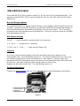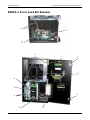
1
Bill Breaker
Field Service Manual
and
Parts Catalog
For all models
500RLC1-2
Rear Load
500C2-2
Front Load
22190006
May, 2008
Rowe International
Bill Breaker Field Service Manual & Parts Catalog
Intentionally Left Blank
22190006
May, 2008
Page 2 of 49
Rowe International
Bill Breaker Field Service Manual & Parts Catalog
Table of Contents
Warranty ........ .......................................... ..................... ..................... .....................
6
Specifications for Mounting (Dimensions, Weights, Electrical)... ..................... .....................
7
Power Cord, Toggle Switch, ON/OFF, and fuse Locations ......... ..................... .....................
8
Changer Installation to meet ADA Requirements .................... ..................... .....................
9
Installing a Rear Load .................................. ..................... ..................... .....................
10,12
Installation of a Front Load Bill Breaker on a base .................. ..................... .....................
11
Set Up/General Operation (one denomination (-1) models without coin hoppers)....................
13
Set Up/General Operation (one denomination (-1) models with coin hoppers) .. .....................
15
Set Up/General Operation (two denomination (-2) models without coin hoppers)....................
16
Set Up/General Operation (two denomination (-2) models with coin hoppers) ..
“Cassettes $1, $5”............................ ..................... .....................
Reconciliation .................................. ..................... .....................
Program Reset ................................. ..................... .....................
Currency Cassette Configuration......... ..................... .....................
“Out of Currency” Currency Load / Reconciliation ........ .....................
“Out of Coin” Coin Load / Reconciliation..................... .....................
.....................
.....................
.....................
.....................
.....................
.....................
.....................
19
21
22
23
24
25
26
Printer Set Up .. .......................................... ..................... ..................... .....................
27
Configuration Print ...................................... ..................... ..................... .....................
28
Help Code Chart.......................................... ..................... ..................... .....................
29
Help Code Processing................................... ..................... ..................... .....................
Stacker Full
Out Of Currency
Bill Acceptor Error
No Stacker Attached
Bill Jam
31
Status Report .. .......................................... ..................... ..................... .....................
32
External Status Report Key and Switch ........... ..................... ..................... .....................
32
Voltage Test Points ...................................... ..................... ..................... .....................
33
One Denomination, Model F50, Bill Dispenser Maintenance Schedule .............. .....................
34
Two Denomination, Model F53, Bill Dispenser Maintenance Schedule .............. .....................
34
Mars Bill Acceptor........................................ ..................... ..................... .....................
New Bill Design Updates
DIP Switch Settings
Cleaning
For More Information
35
22190006
May, 2008
Page 3 of 49
Rowe International
Bill Breaker Field Service Manual & Parts Catalog
Coin Hoppers ... .......................................... ..................... ..................... .....................
United States dimes (10¢) and dime sized tokens
Optional Hopper Extensions
Cleaning
For More Information
36
Parts: 500C2-2 .......................................... Front Load, 2 denomination dispenser.............
500RL-2 .....................Rear Load, 2 denomination dispenser ............. .....................
500RLC2-2 .................Rear Load, 2 coin hopper, 2 denomination dispenser...............
500RLC2-1 .................Rear Load, 2 coin hopper, 1 denomination dispenser...............
500C2-1 .....................Front Load, 2 coin hopper, 1 denomination dispenser..............
Printer . .......................................... ..................... ..................... .....................
38
40
42
44
46
48
Cassette ......... .......................................... ..................... ..................... .....................
49
Fujitsu
Fujitsu
Fujitsu
Fujitsu
F53
F50
F53
F50
Cash Dispenser Operator’s Guide Included (Rowe part number 22214101)
Cash Dispenser Operator’s Guide Included (Fujitsu part number P2KD11078-B002/6)
Currency Loading Procedure (Fujitsu part number P1KD02881-B001)
Currency Loading Procedure (Fujitsu part number part number P1KD11078-B002/6)
NOTE: All Fujitsu manuals above are separate from this manual.
22190006
May, 2008
Page 4 of 49
Rowe International
Bill Breaker Field Service Manual & Parts Catalog
Intentionally Left Blank
22190006
May, 2008
Page 5 of 49
Rowe International
Bill Breaker Field Service Manual & Parts Catalog
Warranty
Rowe extends the original operator of this equipment the following warranty:
All parts are guaranteed to be free of defects in material and workmanship for the specific periods
that follow. Rowe agrees to repair, without charge during such period, any part that proves
defective upon examination by Rowe. All costs of shipping an allegedly defective part to Rowe’s
offices shall be borne by the original operator. Rowe will pay the shipping costs for the replacement
of defective parts.
Electrical Circuit Boards
Electrical and Mechanical Parts
Lamps
1 year from date of purchase
1 year from date of purchase
90 days from date of purchase
In the case of parts supplied to Rowe as components, Rowe extends the same warranty period as
extended by the original manufacturer.
The above warranty applies provided that all parts of the product have been serviced properly as
directed in the service manual, and provided the alleged defective part, upon examination by
Rowe, shall prove to be thus defective. Under no circumstances shall Rowe be liable for any
incidental, consequential, or special damages, losses or expenses arising from or in connection with
the use of, or the inability to use, the product for any purpose. Rowe reserves the right to make
any changes or improvements in products theretofore manufactured or sold.
This warranty will not apply to any part that has been subjected to accident, abuse, or misuse.
ROWE INTERNATIONAL EXTENDS NO WARRANTY, EXPRESSED OR IMPLIED, TO
PURCHASERS OR USERS OF ITS PRODUCTS EXCEPT AS HEREIN SET FORTH, WHETHER BY
OPERATION OF LAW OR OTHERWISE.
22190006
May, 2008
Page 6 of 49
Rowe International
Bill Breaker Field Service Manual & Parts Catalog
Specifications for Mounting
Model:
Type:
Number of Bill
Denominations Dispensed:
Cabinet Dimensions
- Width:
- Depth:
- Height:
Face Plate (DxWxH):
Approx. Shipping Weight:
Power*
- Line Voltage:
- Idle:
- Active:
Model:
Type:
Number of Bill
Denominations Dispensed:
Cabinet Dimensions
- Width:
- Depth:
- Height:
Face Plate (DxWxH):
Approx. Shipping Weight:
Power*
- Line Voltage:
- Idle:
- Active:
500-1
500C1-1, 500C2-1
500RL-1
500RLC1-1
500RLC2-1
Front Load
Rear Load
Rear Load
1
1
1
19 in.
17.25 in.
32 in.
18 in.
17.25 in.
16.5 in.
18 in.
17.25 in
32 in.
n/a
.125” x 23.75” x 21.75”
.125” x 23.75” x 37.25”
500-1:
95 lbs.
500C1-1: 100 lbs.
500C2-1: 105 lbs.
87 lbs.
500C1-1: 120 lbs.
500C2-1: 125 lbs.
115 VAC, 95-125 VAC
115 VAC, 95-125 VAC
115 VAC, 95-125 VAC
110/115 AC; 60Hz, 130w/1.5A
110/115 AC; 60Hz, 130w/1.5A
110/115 AC; 60Hz, 130w/1.5A
110/115 VAC; 60Hz,
230w / 3.5A
110/115 VAC; 60Hz,
230w / 3.5A
110/115 VAC; 60Hz,
230w / 3.5A
500-2
500C1-2, 500C2-2
500RL-2
500RLC2-2
500RLC1-2
Front Load
Rear Load
Rear Load
2
2
2
19 in.
17.25 in.
32 in.
18 in.
17.25 in.
16.5 in.
18 in.
17.25 in
32 in.
n/a
.125” x 23.75” x 21.75”
.125” x 23.75” x 37.25”
500-2: 115 lbs.
500C1-2: 120 lbs.
500C2-2: 125 lbs.
92 lbs.
500RLC1-2: 125 lbs.
500RLC2-2: 130 lbs.
115 VAC, 95-125 VAC
115 VAC, 95-125 VAC
115 VAC, 95-125 VAC
110/115 AC; 60Hz, 130w/1.5A
110/115 AC; 60Hz,
130w/1.5A
110/115 AC; 60Hz, 130w/1.5A
110/115 VAC; 60Hz,
230w / 3.5A
110/115 VAC; 60Hz,
230w / 3.5A
110/115 VAC; 60Hz,
230w / 3.5A
*No more than three (3) Bill Breaker units may be connected to a single 15 amp circuit.
Rowe International reserves the right to make improvements and changes at any time.
22190006
May, 2008
Page 7 of 49
Rowe International
Bill Breaker Field Service Manual & Parts Catalog
Power Cord, Toggle Switch, ON/OFF Location, and Fuses
Fuse, 3.5 amp
BK/5506-5-R
Power Cord Receptacle
Figure 1
Printer
Power
Supply
Power Cord
Rear Load Models
The Power Cord receptacle is located on the cabinet bottom panel below the AC power and switch
box (shown above in Figure 1).
Front Load Models
The power cord receptacle is located on the cabinet bottom panel in the rear, left corner.
Fuse Locations
There are two fuses used in the Bill Breaker.
1) Fuse, 3.5 amp BK/5506-5-R: Located in the power cord receptacle at the bottom and rear
of the toggle switch box (shown above in Figure 1).
2) Fuse F3.15AH, 250v slow blow: Located on the power supply assembly (see figure below).
IMPORTANT NOTE
Plugging any device (such as drill, vacuum, etc.)
into the printer power receptacle may cause a
blown fuse.
Fuse F3.15AH,250 V
Slow Blow
Power Supply Assembly
22190006
May, 2008
Page 8 of 49
Rowe International
Bill Breaker Field Service Manual & Parts Catalog
Changer Installation to Meet ADA Requirements
The American Disabilities Act requires unobstructed access to equipment. It is to be no
lower than 15 inches and no higher than 54 inches from the ground. This requirement
must be met whether a changer is installed on a base, on a table, or in the wall.
Wall
Bill Breaker
Max 54”
500RL-1
500RLCX-1
500RL-2
500RLCX-2
43 Max
33 Max
43 Max
33 Max
FLOOR
22190006
May, 2008
Page 9 of 49
Rowe International
Bill Breaker Field Service Manual & Parts Catalog
Installing a Rear Load
General
For all methods of installation, locate a convenient power source and be sure that the bill
changer is mounted level.
The Rear Load Bill Breaker is primarily designed to be flush mounted on a wall with the
cabinet itself protruding through a hole (or cutout) in the wall. The cutout should be
determined by the cabinet dimensions shown on page 7. The faceplate, attached to the
cabinet, is mounted tight (or flush) against the outside surface of the wall and secured
with two angle braces (one on each side of the bill changer). See below for an illustration
of this mounting technique. The wall should be flat and vertical so that when the changer
is mounted to the wall, no gap exists between the wall and the stainless steel panel. If the
changer is mounted on an outside wall, apply a liberal bead of sealant or caulking to the
backside of the panel near the four outside edges to ensure a good weather seal and
discourage prying.
Typical Wall Mounting
1. Refer to page 6 for cabinet dimensions and then make an opening in the wall just
large enough for the changer cabinet. (Determine the bill changer mounting height
before you start cutting into the wall.)
2. Depending on the wall thickness, locate and drill three ¼-inch diameter (or larger)
holes in each side of the cabinet as shown below. Drill the holes in the angle-iron
to match the holes in the cabinet.
3. Set the bill changer in the opening in the wall and apply a bead of sealant or
caulking to the back side of the faceplate. Position the faceplate tight against the
wall and fasten the angle braces to the sides of the bill changer with ¼-inch
diameter screws or screws that match the holes drilled in Step#2. Make sure that
the faceplate is tight against the wall.
22190006
May, 2008
Page 10 of 49
Rowe International
Bill Breaker Field Service Manual & Parts Catalog
Installing a Front Load Bill Breaker on a Base
(Models 500-1, 500CX-1, 500-2, 500CX-2
Important Note:
Do not position the rear side of the base flush with a wall. The rear side of the cabinet
must hang over the rear side of the base b 2.5 inches to allow for the power cord to mount
to the underside rear corner of the cabinet.
1. Open cabinet door.
2. Remove the dispensing module from the cabinet.
3. Temporarily bolt the cabinet on the base using 2 of the mounting screws.
Four ¼ x 20 mounting screws are stored in the four holes in top of the base.
4. Place the base and cabinet in position (cabinet can be placed tight against a wall).
5. Mark the position of the base on the floor.
6. Separate the base and cabinet.
7. Using lag bolts in the four .375” openings, mount base to the floor.
8. Partially insert the ¼ x 20 screw into the left rear hole so that the cabinet can be
positioned over the key hole screw opening.
9. Slide the cabinet into place and insert the remaining 3 mounting screws.
10.The left rear screws can be tightened by reaching around the silver power/control
panel.
11.Insert the power cord into the AC outlet found on the bottom left rear cabinet corner.
12.For extra security, additional screws can be inserted through the rear cabinet panel
into the wall.
Remove
Dispensing
Module
Power/Control
Panel
(2) ¼ x 20
Mounting Screws
this side
22190006
(2) ¼ x 20
Mounting Screws
this side
May, 2008
Page 11 of 49
Rowe International
Bill Breaker Field Service Manual & Parts Catalog
REAR VIEW
BOTTOM VIEW
22190006
May, 2008
Page 12 of 49
Rowe International
Bill Breaker Field Service Manual & Parts Catalog
Set Up/General Operation of One Denomination (-1)
Models without coin hoppers
(For Models 500-1, 500RL-1)
When you first receive your new Bill Breaker, it will need to be configured for your use.
Some options may be factory set but they are generic and will need to be reset.
There are three toggle switches on the bottom of the main board, located in the top left
side of the cabinet rear panel for front load models. For rear load models, the three toggle
switches are found on the AC power and switch box (see page 8).
These are labeled:
Resume:
Brings you to the next part of the program.
Pressing the resume switch confirms and enters the data
Status:
Moves the cursor on the display during the set up procedure.
Pressing the status switch moves the cursor through the data fields
from left to right
Recon:
Toggles between all yes/no questions, as well as all numeric questions.
Pressing the recon switch changes the data in the data field
Also located in this area are the connections for the internal printer, if used, a power
outlet, and the printer port connection. The main power switch is also located in this area.
The main board can be accessed by removing the screw that holds the control panel
down.
This is a good time to check any connections that may have come loose during shipping,
check that the cash dispenser is secure, and remove all packing materials which maybe
around the cash dispenser. Check that the Mars bill validator, harnesses, and bill box are
secure.
The Bill Breaker can be mounted to a base style cabinet or installed into a wall if you have
a Rear Load model. Securely bolt down the Bill Breaker whether on a base or in a wall.
The power required is 110 volts with a 15-amp surge.
22190006
May, 2008
Page 13 of 49
Rowe International
Bill Breaker Field Service Manual & Parts Catalog
(continued)
Set Up/General Operation of One Denomination (-1)
Models without coin hoppers
(For Models 500-1, 500RL-1)
1.
2.
3.
4.
5.
6.
Load currency magazine with at least 50 bills (see separate Fujitsu manual)
Turn on the main power switch to the Bill Breaker.
The display will read “Cassette 1 = $1" N
Cycle the Recon switch to respond to Y if $1 bills are to be dispensed. Go to $5.
Press Resume switch until the desired denomination is found.
Press the resume switch. The display reads “enter machine #”. Enter the
appropriate machine number by using the recon switch, which changes the value of
the data, and the status switch, which will move the cursor from left to right. After
entering the machine number, press the resume switch to register the entered
data.
7. The display will read, “Printer installed”. If there is a printer, Enter “Y” toggling the
Recon switch.
8. The display will read, “Enter bill load”. Enter the pre-determined bill load into the
response area and press resume to enter the data. The display will read “$XXXXX
load OK? Y/N”
9. Press resume if the load amount is correct.
The following area will assist you in setting up your Bill Breaker to handle the
denominations of your choice. The display will cycle through all denominations
beginning with $1 and ending with $100. ($50's & $100's can only be enabled with
a Mars 2811 Bill Validator) We ship a Mars Bill Validator that accepts up to a $20
bill, to accept $50's and $100's an optional Mars 2811 is required. The display will
read, “Enable $5 entry?” Respond “Y” and press the resume switch. Continue this
way for each denomination you would like accepted. Enter number and press the
Recon switch.
After all denominations have been configured, press the resume switch, and the display
will read “configuration OK?” Respond “Y” and press the resume switch. Display will read,
“printing report”. Display will then read “printed report OK?” Respond “Y” even if you don't
have a printer and press the resume switch. Display will now read “ready to accept bill”.
22190006
May, 2008
Page 14 of 49
Rowe International
Bill Breaker Field Service Manual & Parts Catalog
Set Up/General Operation of One Denomination (-1)
Models with coin hoppers
(For Models 500C1-1, 500C2-1, 500RLC1-1, 500RLC2-1)
Switches
Results
Resume
Status
Recon
Brings you to the next part of the program.
Moves the cursor on the Display during the setup procedures.
Toggles between all yes and no questions and is used for all numeric
questions.
Display
Function
Cassette 1 = $1 Y/N
Load magazine with at least 50 bills (see
separate Fujitsu manual).
Shows magazine denomination.
Press Recon to change N to Y if $1 bills are
being dispensed. Press Resume to continue.
Establishes machine identification; press
Resume switch
Answer yes or no using Recon switch. Then
press Resume switch.
Enter total dollar value inside magazines using
Status & Recon switches.
Verifies total dollar value inside magazines
Checks to see if coin dispenser #1 is installed
The total # of coins using Status & Recon
switches.
Verifies the # of coins
x.25 – quarters using Status & Recon switches.
Checks to see if coin dispenser #2 is installed
Allows you to choose which bills you want
accepted (Example enable $100 <Y>)
Number of notes to be dispensed using Status &
Recon switches.
Number of coins to be dispensed from Coin
Hopper #1 using Status & Recon switches.
Number of coins to be dispensed from Coin
Hopper #2 using Status & Recon switches.
If you have a printer, prints out machines
configuration. “No” brings you back to the
beginning
Press Recon switch for “Y” yes.
Bill Breaker is now ready.
(Press Resume switch after completing each function).
Enter Mach #
Printer Installed
Enter bill load in $
xxxxx Load OK Y/N?
Coin Dispenser #1 Y/N?
a) If yes, Resume Ent Load In # Pieces
b) # of pieces OK? _ _ _
c) Enter piece value x.xx
Coin Dispenser #2 Y/N?
Enable $1 through $100
# From $1 Cassette
# From Coin #1
# From Coin #2
Configuration OK Y/N
Printed report OK? Y/N
“Ready to Accept Bill Y?”
22190006
May, 2008
Page 15 of 49
Rowe International
Bill Breaker Field Service Manual & Parts Catalog
Set Up/General Operation of Two Denomination (-2)
Models without coin hoppers
(For Models 500-2, 500RL-2)
When you first receive your new Bill Breaker, it will need to be configured for your use.
Some options may be factory set but they are generic and will need to be reset.
There are three toggle switches on the bottom of the main board, located in the top left
side of the cabinet (rear).
These are labeled:
Resume:
Brings you to the next part of the program.
Pressing the resume switch confirms and enters the data
Status:
Moves the cursor on the display during the set up procedure.
Pressing the status switch moves the cursor through the data fields
from left to right
Recon:
Toggles between all yes/no questions, as well as all numeric questions.
Pressing the recon switch changes the data in the data field
Also located in this area are the connections for the internal printer, if used, a power
outlet, and the printer port connection. The main power switch is also located in this area.
The main board can be accessed by removing the screw that holds the control panel
down.
This is a good time to check any connections that may have come loose during shipping,
check that the cash dispenser is secure, and remove all packing materials which maybe
around the cash dispenser. Check that the Mars bill validator, harnesses, and bill box are
secure.
The Bill Breaker can be mounted to a base style cabinet or installed into a wall if you have
a Rear Load model. Securely bolt down the Bill Breaker whether on a base or in a wall.
The power required is 110 volts with a 15-amp surge.
22190006
May, 2008
Page 16 of 49
Rowe International
Bill Breaker Field Service Manual & Parts Catalog
(continued)
Set Up/General Operation of Two Denomination (-2)
Models without coin hoppers
(For Models 500-2, 500RL-2)
NOTE: Resume, Status, and Recon switches are located in the AC Power & switch box
inside the cabinet.
Switches
Resume
Results
Brings you to the next part of the program.
Status
Moves the cursor on the display during the setup procedure.
Recon
Toggles between all yes and no questions and is used for all
numeric questions.
Display
Function
Cassettes $1, $5
Shows cassette denomination. Load each
cassette with at least 50 bills (see separate
Fujitsu manual) and press Resume.
Establishes machine ID; choose number
using Recon switch; press Resume.
Enter total dollar value inside cassettes
using Status & Recon switches
Verifies total dollar value inside cassettes.
Use Recon switch to answer Y/N. Press
Resume.
Enter Y/N using Recon switch. Press
Resume.
If N … begin instructions on next page
at “Enable $5 entry”
Enter number of minutes for which bills will
be entered before automatic shutdown
using Recon. Press Resume.
Enter number of bills inserted before
shutdown occurs using Recon. Press
Resume.
Enter Machine #
Enter Bill Load in $
$ XXXX Load OK Y/N
Max Trans Rate Y/N?
Number of Minutes =
Number of Bills =
22190006
(Press Resume switch after completing each function).
May, 2008
Page 17 of 49
Rowe International
Bill Breaker Field Service Manual & Parts Catalog
(continued)
Set Up/General Operation of Two Denomination (-2)
Models without coin hoppers
(For Models 500-2, 500RL-2)
# Minutes Shutdown =
Enable $5 Entry ?
Configuration OK Y/N
22190006
Enter number of minutes unit will be
shutdown before automatically returning
back to service using Recon. NOTE: Time
must be greater than 1 minutes with 99
being shutdown requiring manual restart.
Press Resume.
Toggle with Recon for Y/N, press Resume.
Continue for $10, $20, $50, $100
denominations.
If correct, press Resume. With a printer, the
machine configuration prints out. “No”
returns to the beginning.
May, 2008
Page 18 of 49
Rowe International
Bill Breaker Field Service Manual & Parts Catalog
Set Up/General Operation of Two Denomination (-2)
Models with coin hoppers
(For Models 500C1-2, 500C2-2, 500RLC1-2, 500RLC2-2)
Switches
Results
Resume
Brings you to the next part of the program.
Status
Moves the cursor on the Display during the setup procedures.
Recon
Toggles between all yes and no questions and is used for all numeric
questions.
Display
Function
Cassette $1, $5
Shows cassette denomination. Load each
cassette with at least 50 bills (see separate
Fujitsu manual) and press Resume.
Establishes machine ID; choose number
using Recon switch; press Resume.
Answer yes or no using Recon switch. Then
press Resume switch.
Enter total dollar value inside cassettes
using Status & Recon.
Verifies total dollar value inside cassettes
Checks to see if coin dispenser #1 is
installed
The total # of coins using Status & Recon.
Enter Mach #
Printer Installed
Enter bill load in $
$ XXXX Load OK Y/N?
Coin Dispenser #1 Y/N?
a) If yes, Resume Ent Load In #
Pieces
b) # of pieces OK? _ _ _
c) Enter piece value x.xx
Coin Dispenser #2 Y/N?
Enable $1 through $100
# From $1 Cassette
# From $5 Cassette
# From Coin #1
# From Coin #2
22190006
(Press Resume switch after completing each function).
Verifies the # of coins
x.25 – quarters using Status & Recon.
Checks to see if coin dispenser #2 is
installed
Allows you to choose which bills you want
accepted (Example enable $100 <Y>)
Number of notes to be dispensed from $1
Cassette using Status & Recon switches.
Number of notes to be dispensed from $5
Cassette using Status & Recon switches.
Number of coins to be dispensed from Coin
Hopper #1 using Status & Recon switches.
Number of coins to be dispensed from Coin
Hopper #2 using Status & Recon switches.
May, 2008
Page 19 of 49
Rowe International
Max Trans Rate Y/N?
Number of Minutes =
Number of Bills =
# Minutes Shutdown =
Enable $5 Entry ?
Configuration OK Y/N
22190006
Bill Breaker Field Service Manual & Parts Catalog
Enter Y/N using Recon switch. Press
Resume.
If N … begin instructions below at
“Enable $5 entry”
Enter number of minutes for which bills will
be entered before automatic shutdown
using Recon. Press Resume.
Enter number of bills inserted before
shutdown occurs using Recon. Press
Resume.
Enter number of minutes unit will be
shutdown before automatically returning
back to service using Recon. NOTE: Time
must be greater than 1 minutes with 99
being shutdown requiring manual restart.
Press Resume.
Toggle with Recon for Y/N, press Resume.
Continue for $10, $20, $50, $100
denominations.
If correct, press Resume. With a printer, the
machine configuration prints out. “No”
returns to the beginning.
May, 2008
Page 20 of 49
Rowe International
Bill Breaker Field Service Manual & Parts Catalog
Cassettes $1, $5 for Two Denomination Models
“Cassettes $1, $5” showing on display indicates normal two denomination Bill Breaker
start up identifying that the cassettes are set up to handle $1 and $5 notes. “Cassettes
$5, $10” showing on display indicates that the cassettes are set up to handle $5 and $10
notes and so on. Change the cassette configuration on page 24 in “Currency Cassette
Configuration”
“Cassette 1 = $1 N” showing on display indicates normal one denomination Bill Breaker
start up. See pages 13-15 for set up of one denomination models.
22190006
May, 2008
Page 21 of 49
Rowe International
Bill Breaker Field Service Manual & Parts Catalog
Reconciliation
Press the Recon switch. Each cycle of the switch will display a different line item. To end
the cycle, press the Resume switch moving on to the next line item.
The display will prompt, “Print recon Y/N?”
Select “Y” and press the resume switch. The reconciliation report prints and the display
reads “printed report OK?”
Respond “Y” and press the resume switch. The display will read “? CLR recon data Y/N?”
Respond to the CLR Recon Data message above by selecting ”Y” and press the resume
switch. Bill Breaker will read “Ready To Accept Bills”.
IMPORTANT NOTE:
The Bill Breaker MUST BE RECONCILED BEFORE ANY EXSISTING OPTIONS ARE
CHANGED. This does not apply to initial setup, ONLY if you wish to change any preexisting options or settings.
Failure to do so will delete all bookkeeping functions and events for the current period.
Sample Reconciliation Report
RECONCILIATION RPT
F53C_2_5
MACHINE #- - - - 1
RECON AUDIT - - 0
MAINTENANCE - - 17
DOC STACKED - - 5
STACK DOLLAR
$46
REJECTED - - - - - $0
CAS#1 DOLLAR - $15
CAS#2 DOLLAR - $10
BILL LOAD - - - - $3000
BILLS PAID - - - - $25
BILLS LEFT - - - - $2975
#1 COIN LOAD - $250.00
#1 COIN PAID $21.00
#1 COIN LEFT $229.00
- - - MACHINE TOTALS - - TTL LOAD $3250.00
TTL PAID $46.00
TTL LEFT $3204.00
22190006
May, 2008
Page 22 of 49
Rowe International
Bill Breaker Field Service Manual & Parts Catalog
Program Reset
Before starting the reset process, a reconciliation “Recon” must be completed.
Turn power OFF.
Hold down Resume switch.
While holding down Resume switch, turn power ON and hold Resume down for several
seconds. The following prompts will be displayed:
•
•
•
•
•
“Hold Resume To CONFG”
“Release Resume”
“Reset Machine Y/N”
Answer “Y” by cycling Recon switch
“Cassettes $1 $5” (depending on how the cassettes are set up)
Follow display prompts.
22190006
May, 2008
Page 23 of 49
Rowe International
Bill Breaker Field Service Manual & Parts Catalog
Currency Cassette Configuration
The following information will allow you to set up or modify the denominations of currency
that your Bill Breaker will dispense.
Note: It is important to complete “Reconciliation” and “Reset” before changing cassette
configuration.
The currency cassettes have magnets built into them. The currency dispenser “reads”
these magnet configurations, and relays this data to the Bill Breaker’s main board. It
cannot be stressed enough that extreme care must be taken while changing
these configurations. The Bill Breaker will only read these magnet settings for
denomination recognition. It does not matter if the correct denomination is
placed into the cassettes, because if the magnets are set wrong, the dispenser
will dispense incorrectly.
To access the magnets open the cassette. There is a metal clip which is part of the top
cover. Remove bracket to access magnets. There are 4 magnet positions in each cassette.
They are marked A,B,C, and D on the top lid. IMPORTANT NOTE: The position of the
white side and white top face is critical. The magnet’s white side faces the
outside cassette edge. The white top faces the top cassette edge. If magnets are
in the incorrect position, the error code is “?Wrong Cassette?”. One end and one
side of the magnets is painted, while the other end and side is not. When inserting a
magnet, the paint goes towards the top and the front of the cassette. The top of the
cassette is where the letters ABCD appear. The front of the cassette is where the button is
located to open the top lid. For more information and a picture of the magnet
assembly, please see chapter 2 of the Fujitsu dispensers operators guide.
TYPE
1
2
3
4
DENOMINATION
$1.00
$5.00
$10.00
$20.00
POSITIONS
D
C
D&C
B
Note : Loading Currency into the cassettes must be done properly to assure the reliability
of the Bill Breaker. Take your time while loading currency and never try to insert more
than 30 bills at a time until you reach the desired amount. PLEASE refer to the section in
the enclosed “Fujitsu Cash Dispensers Operators Guide” pertaining to loading currency.
22190006
May, 2008
Page 24 of 49
Rowe International
Bill Breaker Field Service Manual & Parts Catalog
“Out of Currency” Currency Load / Reconciliation
The Bill Breaker will shut down and will not accept further currency if:
•
•
•
EITHER cassette is drawn down to approximately 15-35 notes
EITHER coin hopper is drawn down to about 100 coins
the Bill Validator stacker is full
You must perform a reconciliation and reload the cassettes with the same amount of
money that you originally started with. This preserves the "Bill Load" data in the Bill
Breaker.
Press the resume switch. The display will prompt, “Print recon Y/N?”
Select “Y” and press the resume switch. The reconciliation report prints and the display
reads “printed report OK?”
Respond “Y” and press the resume switch. The display will read “? CLR recon data Y/N?”
Remove the Mars stacker, both “empty” cassettes, and inspect the reject bin, removing all
rejected bills. Any bills found here must be returned with the cassettes and stacker and
counted with them. It is still classified as bills from the cassettes. Return the empty reject
bin into its slot.
Install an empty stacker on the validator and two full cassettes in the dispenser. Respond
to the CLR Recon Data message above by selecting ”Y” and press the resume switch. Bill
breaker will read “Ready To Accept Bills”.
IMPORTANT NOTE:
The Bill Breaker MUST BE RECONCILED BEFORE ANY EXSISTING OPTIONS ARE
CHANGED. This does not apply to initial setup, ONLY if you wish to change any preexisting options or settings.
Failure to do so will delete all bookkeeping functions and events for the current period.
22190006
May, 2008
Page 25 of 49
Rowe International
Bill Breaker Field Service Manual & Parts Catalog
“Out of Coin” Coin Load / Reconciliation
The Bill Breaker will shut down and will not accept further currency if:
hopper is drawn down to about 100 coins.
EITHER coin
You must perform a reconciliation and reload the hopper with the same amount of money
that you originally started with. This preserves the "Coin Load" data in the Bill Breaker.
Press the resume switch. The display will prompt, “Print recon Y/N?”
Select “Y” and press the resume switch. The reconciliation report prints and the display
reads “printed report OK?”
Respond “Y” and press the resume switch. The display will read “? CLR recon data Y/N?”
Prompts to purge coin hoppers are as follows:
• “Purge Coin Y/N”
• “Purge Coin?”
These messages repeat if a second hopper is used.
Respond to the CLR Recon Data message above by selecting ”Y” and press the resume
switch. Bill breaker will read “Ready To Accept Bills”.
IMPORTANT NOTE:
The Bill Breaker MUST BE RECONCILED BEFORE ANY EXSISTING OPTIONS ARE
CHANGED. This does not apply to initial setup, ONLY if you wish to change any preexisting options or settings.
Failure to do so will delete all bookkeeping functions and events for the current period.
22190006
May, 2008
Page 26 of 49
Rowe International
Bill Breaker Field Service Manual & Parts Catalog
Printer Set Up
Make sure the power is OFF.
1) Attach 3 pin “D” connector to P7 “D” connector (“D” connector in rear loads is laying
on the bottom of the cabinet - - “D” connector in front load models is located on the
control board cover).
2) Attach printer power supply to the outlet (outlet for rear loads is located at the rear of
the AC power & switch box - - outlet on front loads is on the control board cover). See
diagram below for rear load models.
3) Attach power supply plug connector to the back of the printer.
4) Turn printer ON/OFF switch to ON (printer power switch is located on the right side of
the printer).
Printer
Power
Supply
Rear Load Models
22190006
May, 2008
Page 27 of 49
Rowe International
Bill Breaker Field Service Manual & Parts Catalog
Configuration Print
Make sure printer is connected and turned ON.
While power is ON, hold down the Resume switch for 10 seconds.
Release Resume switch when printing begins.
The printout will show how the Bill Breaker is configured.
Sample Configuration Report
CONFIGURATION RPT
F53C_2_5
MACHINE NUMBER = 1
CASSETTE #1=$1
CASSETTE #2=$5
BILL LOAD = $3000
DISPENSER #1 ENABLED
COIN LOAD=$1000
COIN VALUE=$0.25
DISPENSER #2 DISABLED
PRINTER IS --- ENABLED
TRANSACTION DEFINITIONS
$1
IS ENABLED
-# CAS1=00/$1
-# CAS2=00/$5
-# COIN1=04/0.25
$5
IS ENABLED
-# CAS1=00/$1
-# CAS2=00/$5
-# COIN1=20/0.25
$10 IS ENABLED
-# CAS1=05/$1
-# CAS2=00/$5
-# COIN1=20/0.25
$20 IS ENABLED
-# CAS1=05/$1
-# CAS2=02/$5
-# COIN1=20/0.25
$50 IS DISABLED
$100 IS DISABLED
22190006
May, 2008
Page 28 of 49
Rowe International
Bill Breaker Field Service Manual & Parts Catalog
Help Code Chart
HELP CODE
DESCRIPTION/ CORRECTIVE ACTION
?Out of Currency?
?No top cassette?
Reload cassette or magazine with currency and
reconcile unit, answer “Y” to clear Recon data prompt;
Be sure bill load amount is greater than or equal to
amount of bills in the cassette or magazine,
press Resume switch.
Replace Top Cassette, press resume switch
?No 2nd cassette?
Replace Bottom Cassette, press resume switch
Dispenser Error Code - 1800
Remove top cassette, remove jammed bill, replace
cassette, press resume switch, check for worn pick
rollers.
Remove bottom cassette, remove jammed bill, replace
cassette, press resume switch, check for worn pick
rollers.
Remove Bill Jam In Dispenser, press resume switch
Dispenser Error Code - 2800
Dispenser Error Code – 78xx
In $20
Pay $10.00
Dispenser Error Code – 7A03
Dispenser Error Code – 89xx
?Wrong Cassette?
Bill Acceptor Error
“BILL ACCEPTOR ERROR”
“NO STACKER ATTACHED”
22190006
Bill Jam at BPS Sensor (NOTE: Check to be sure there
is no interference between the dispenser bill exit area
and the bill chute mounted to the cabinet). Remove
jam and press resume. Clean sensors and belts, see
page 33.
Thickness Sensor Error, contact technician to realign
thickness sensor,
Magnet configuration on cassette is wrong –
see pg. 24
Validator isn’t communicating with the host, check
validation harness connections, press resume switch.
If red LED on rear of acceptor is glowing ON and LED
around outside bezel is flashing, the acceptor is
operating normally. If rear LED is flashing, an error
condition exists.
When a bill jams inside the validator, the transaction is
aborted, and the message “Bill Acceptor Error” is displayed.
The jam will have to be cleared before the Bill Breaker can
be put back into operation. To recover from this
condition:
1. Open the Bill Breaker door.
2. Recover jammed bill from the validator head or the
stacker.
3. Press the resume switch to return to run mode.
4. Close Bill Breaker door.
The Bill Breaker senses that the stacker is loose or missing.
The display will read, “No stacker attached”. To recover
from this condition:
1. Open Bill Breaker door.
2. Disconnect and reconnect the stacker to the validator
head assembly.
3. Press the resume switch to return to run mode.
4. Close the Bill Breaker door.
May, 2008
Page 29 of 49
Rowe International
Stacker is Full
? Bill Jam?
In $20 Pay $10
Error Code 7A02
? No Command Finish ?
Blank Display
22190006
Bill Breaker Field Service Manual & Parts Catalog
Stacker has reached its capacity. Empty stacker and
reconcile unit
Remove jammed bill from dispenser; press Resume.
Bill jam occurred between DFSS and BPS sensor.
Remove jammed bill and press Resume. Clean sensors
and belts, see page 33.
Turn power off. Remove EPROM from its socket on
main control PCB and put back in socket.
1. If unit has second display and the second
display is working, (a) check for damaged
display, (b) check for loose harness, (c) swap
displays.
2. If only the bill acceptor activates (bill dispenser
does not cycle as normal) when the unit is
turned off and on, check voltages on main
control PCB at TP1 & TP2. See Page 30.
3. If no power at TP1 & TP2, replace fuse on
power supply. See Page 30.
May, 2008
Page 30 of 49
Rowe International
Bill Breaker Field Service Manual & Parts Catalog
Help Code Chart
HELP CODE
CORRECTIVE ACTION
“BILL JAM”
If an error occurs, the display will show a difference between the dollar value
requested and the dollar value dispensed, along with an error message "Bill
Jam." For example IN $20 PAID $10. To recover from this condition:
1. Open Bill Breaker door.
2. Inspect for currency jam in the Cash dispensers cassettes, or the transport
unit. Note: The highest probability is that the jam occurred in the currency
cassette. Remove all currency from the cassette and reload it.
3. If no jammed bills are found, press Resume. The display will read “? Do
reconciliation?”
4. Respond with “N”. Display will read “? Cont dispense Y/N?”
5. IMPORTANT! Respond with ”Y” and BE PREPARED TO CATCH the remainder of
the currency from the dispenser because the door will be open in the front
load models.
If an error occurs, the display will show a difference between the dollar value
requested and the dollar value dispensed, along with an error message "?Coin
empty or jam?" For example IN $1.00
PAY $0.50. To recover from this
condition:
“?COIN EMPTY OR
JAM?”
“IN $1.00 PAY 0.50”
1)
2)
3)
4)
5)
6)
7)
8)
22190006
Open Bill Breaker door.
Coin hoppers may be low on coins and need refilling.
Be sure coin hopper connector is secured in socket on lower rear corner of hopper.
If using 2 hoppers, hoppers can swap positions to determine if a problem follows the
hopper.
Inspect for coin jam in the coin hoppers. Note: The highest probability is that the jam
occurred in the coin hopper. Remove all coin from the hopper using coin purge cycle. If
2 hoppers are used, rotate them checking to see if problem follows the hopper.
Press Resume. The display will read “? Do reconciliation?”
Respond with “Y”. Display will read “Purge coin, press Resume & follow prompts”
IMPORTANT! Respond with ”Y” and BE PREPARED TO CATCH the remainder of the coin
from the hoppers.
May, 2008
Page 31 of 49
Rowe International
Bill Breaker Field Service Manual & Parts Catalog
Status Report
Every time you press the Status switch, data will appear. Vital information such as
starting amount of currency, amount of currency left, and the dollar amount in the stacker
will be shown on the display. You can also print out all of this data for your records, if you
have a printer.
Hit Resume switch.
Choose Y or N on printing report, hit Resume switch, and the Bill Breaker will return to
normal, “Ready to Accept Bill”.
External Status Report Key and Switch
(for rear load models only)
On the rear load models, this key switch is located on the rear door next to the display.
Insert the key into the switch. Rotating the key to the right will begin the display of vital
information such as starting amount of currency/coin, amount of currency/coin left.
Rotating the key to the left will return to “Ready to Accept Bills”.
22190006
May, 2008
Page 32 of 49
Rowe International
Bill Breaker Field Service Manual & Parts Catalog
Voltage Test Points
The following test points with their voltage settings are found on the main
control board shown in Figure 4.
Test Point
Action
Voltage Expected
Jumper to TP 1 & 9th pin on the
40 pin processor
Occasionally when the unit has
been turned off for long periods
of time, it is necessary to reset
the processor. The action of the
unit will be that the bill
acceptor and dispenser can be
heard activating but the display
is blank. This action puts +5
VDC to the processor for the
reset.
Power to the processor
Power to the processor
Power for RS 232 for dispenser
and PC interface
Power for RS 232 for dispenser
and PC interface
Ground
+5 VDC
TP1
TP 2
TP 3
TP 4
TP 5
TP1
+5 VDC
TP3
+9 to +12 VDC
TP4
-9 to -12 VDC
TP5
GROUND
TP2
+5 VDC
PIN #40
+5 VDC
+5 VDC
+ 9 VDC to +12 VDC
- 9 VDC to - 12 VDC
Ground
PIN #21
Pin #9
on processor
PIN #20
PIN #1
Figure 4
22190006
May, 2008
Page 33 of 49
Rowe International
Bill Breaker Field Service Manual & Parts Catalog
F-50 MAINTENANCE AND INSPECTION SCHEDULE
Adjustment and
Lubrication Item
1 Thickness sensor
inspection
2 Belt tension
inspection
3 Sensor output
check
4 Pick roller
Inspection period
Inspection Description
Four
Months
Eight
Months
Confirm the value of the
amplifier board output.
Inspect the belt tension.
Check the outputs of the
sensors, and clean the dirty
sensors if any.
Change pick roller
One
Year
Others
O
O
O
O
F-53 MAINTENANCE AND INSPECTION SCHEDULE
Adjustment,
Cleaning and
Lubrication Item
Inspection period
Inspection Description
Thickness Sensor
Inspection
Confirm the value of the
amplifier board output
Detection Lever
Inspection
Check whether paper dust is
attached to the thickness
detection
Gate Inspection
Check whether the gate
operates smoothly
Belt Tension
Inspection
Sensor Output
Check
Inspect the belt tension
Carrying Flat Belt
Check
Pick/Sub Roller
Check whether the flat belt is
loose due to its expansion.
Change pick/sub roller
Cleaning Sensors
Clean with soft dry cloth
Cleaning Belts
Clean with soft dry cloth and
Isopropyl Alcohol
Clean with soft dry cloth and
Isopropyl Alcohol
Cleaning Pick and
Sub Roller
22190006
Check the outputs of the
sensors, and clean the dirty
sensors if any.
May, 2008
Four
Months
Eight
Months
One
Year
Others
O
O
O
O
O
O
O
O
O
O
Page 34 of 49
Rowe International
Bill Breaker Field Service Manual & Parts Catalog
Mars Bill Acceptor
The model AE 2611-U5E is used to accept $1, $2, $5, $10 & $20 United States bills. The
optional model AE 2811-U5E is used to accept $1, $2, $5, $10, $20, $50 & $100 United
States bills.
New Bill Design Updates
To update Bill Breaker to handle new bill designs, new software is downloaded into the bill
acceptor. Contact a local MEI distributor to purchase a BPM (Bill Programming Module) or
have the MEI distributor download new software into the bill acceptor. This is a simple
procedure that most operators can do themselves. There is a nominal charge for the BPM
and downloading service.
DIP Switch Settings
1-8 off………. normal operation accepting bills in 4 directions
1, 2 - 8 off………..accept bills in 1 direction
1-2 off, 3 on, 4 – 8 off…………..high security feature off
Cleaning
It is time to clean the bill acceptor when bills are being returned to patrons at an
unacceptable rate. Turn Bill Breaker power off. Lift chrome plated rod at the rear of the
bill acceptor pulling the bill track out toward you. See Figure 1. Using a clean cloth
dampened with IPA (isopropyl alcohol) wipe the bill track and white feed rollers removing
dirt and ink. Also wipe clean the prism at the bottom of the bill box.
Replace the bill track and bill box. Turn Bill Breaker power on.
For More Information
Contact the www.meiglobal.com for more detailed service and maintenance information.
Lift this chrome
plated rod
Figure 1
22190006
May, 2008
Page 35 of 49
Rowe International
Bill Breaker Field Service Manual & Parts Catalog
Coin Hoppers
The MK IV Universal Hoppers are used to dispense coins and tokens. The standard
hopper set up will reliably dispense United States nickel to dollar sized coins and tokens.
United States dimes (10¢) and dime sized tokens
A specially designed elevator track is needed to handle the United States dime and tokens
smaller than a dime. Contact Rowe International for more information.
Optional Hopper Extensions
Optional hopper extensions are available that hold an additional 400 quarters ($100).
Cleaning
Periodically remove hopper by sliding hopper out of the slide plate and socket. Turn the
hopper upside down shaking out the dirt. Canned air can also be used. Using a clean
cloth dampened with IPA (isopropyl alcohol) wipe the debris inside of the hopper. Focus
the canned air and wiping action toward the count sensor located above the coin exit
area. Also us a “scrubby” type pad to wipe away accumulated dirt on the low level sensor
plates at the bottom of the hopper.
For More Information
Contact the www.moneycontrols.com for more detailed service and maintenance
information.
22190006
May, 2008
Page 36 of 49
Rowe International
Bill Breaker Field Service Manual & Parts Catalog
Intentionally Left Blank
22190006
May, 2008
Page 37 of 49
Rowe International
Bill Breaker Field Service Manual & Parts Catalog
500C2-2 Front Load Bill Breaker
2
9
10
2
1
4
11
8
7
4
5
6
22190006
3
May, 2008
Page 38 of 49
Rowe International
Bill Breaker Field Service Manual & Parts Catalog
500C2-2 Front Load Bill Breaker
(with 2 denomination bill dispenser and 2 coin
hoppers)
Ref.
Part No.
Description
Qty
Cabinet Assembly Internal View
Ref.
1
22196101
Display
1
2
22196201
Main Harness
1
3
22135607
Mars 2611 Bill Acceptor $1, 2, 5, 10, 20 with 500 Bill Box
1
22135608
Mars 2811 Bill Acceptor $1, 2, 5, 10, 20, 50, 100 with 500 Bill Box (optional)
1
4
35027809
T-Handle Assembly with Hardware
2
25223407
Lock Cylinder with 2 Keys
2
22197301
Cassette - No Lock
2
22197401
Cassette - with Lock (optional)
2
22197501
Cassette Lock (optional)
2
6
22197201
Fujitsu F53 Dispenser for 500-2
1
7
22196801
DB9 Dispenser Harness
1
8
22196701
8 Pin Dispenser Power Harness
1
5
9
22196301
Power Supply
1
10
22196001
Logic Printed Circuit Board
1
11
22203301
Coin Hoppers
1 or 2
NOT SHOWN
22199701
22190006
Power Cord
1
May, 2008
Page 39 of 49
Rowe International
Bill Breaker Field Service Manual & Parts Catalog
500RL-2 Rear Load Bill Breaker
22190006
May, 2008
Page 40 of 49
Rowe International
Bill Breaker Field Service Manual & Parts Catalog
500RL-2 Rear Load Bill Breaker
(with 2 denomination bill dispenser)
Ref.
Part No.
1
22135607
22135608
22196202
22196101
35027809
25223407
22203501
22197301
22197401
22197501
22199201
22196701
22196801
22196001
22196301
22206001
2
3
4
5
6
7
8
9
10
11
12
NOT SHOWN
22199701
22190006
Description
Qty
Cabinet Assembly Internal View
Mars 2611 Bill Acceptor $1, 2, 5, 10, 20 with 500 Bill Box
Mars 2811 Bill Acceptor $1, 2, 5, 10, 20, 50, 100 with 500 Bill Box (optional)
Main Harness
Display
T-Handle Assembly with Hardware
Lock Cylinder with 2 Keys
Fujitsu F53 Dispenser for 500RL-2
Cassette - No Lock
Cassette - with Lock (optional)
Cassette Lock (optional)
Citizen Printer (optional)
8 Pin Dispenser Power Harness
DB9 Dispenser Harness
Logic Printed Circuit Board
Power Supply
Attendant Access Switch with 2 keys
Ref.
1
1
1
2
2
2
1
2
2
2
1
1
1
1
1
1
Power Cord
1
May, 2008
Page 41 of 49
Rowe International
Bill Breaker Field Service Manual & Parts Catalog
500RLC2-2 Rear Load Bill Breaker
22190006
May, 2008
Page 42 of 49
Rowe International
Bill Breaker Field Service Manual & Parts Catalog
500RLC2-2 Rear Load Bill Breaker
(with 2 coin hoppers & 2 denomination bill dispenser)
Ref.
Part No.
1
22135607
22135608
22196202
22196101
35027809
25223407
22203501
22197301
22197401
22197501
22199201
22196701
22196801
22196001
22196301
22206001
22203301
Optional
2
3
4
5
6
Optional
Optional
7
8
9
10
11
12
13
NOT SHOWN
22199701
22190006
Description
Qty
Cabinet Assembly Internal View
Mars 2611 Bill Acceptor $1, 2, 5, 10, 20 with 500 Bill Box
Mars 2811 Bill Acceptor $1, 2, 5, 10, 20, 50, 100 with 500 Bill Box
Main Harness
Display
T-Handle Assembly with Hardware
Lock Cylinder with 2 Keys
Fujitsu F53 Dispenser for 500RLC2-2
Cassette - No Lock
Cassette - with Lock
Cassette Lock
Citizen Printer (optional)
8 Pin Dispenser Power Harness
DB9 Dispenser Harness
Logic Printed Circuit Board
Power Supply
Attendant Access Switch with 2 keys
Coin Hopper(s)
Ref.
1
1
1
2
2
2
1
2
2
2
1
1
1
1
1
1
Power Cord
1
May, 2008
Page 43 of 49
Rowe International
Bill Breaker Field Service Manual & Parts Catalog
500RLC2-1 Rear Load Bill Breaker
1
3
2
12
3
4
6
2
10, 11
9
8
7
4
5
22190006
May, 2008
Page 44 of 49
Rowe International
Bill Breaker Field Service Manual & Parts Catalog
500RLC2-1 Rear Load Bill Breaker
(with 2 Coin Hoppers and 1 denomination
bill dispenser)
Ref.
Part No.
1
22135607
22135608
22196202
22196101
35027809
25223407
22203601
22203301
Optional
2
3
4
5
6
7
8
9
10
11
12
22218001
22196801
61188701
22196301
22206001
NOT SHOWN
22199701
22190006
Description
Qty
Cabinet Assembly Internal View
Mars 2611 Bill Acceptor $1, 2, 5, 10, 20 with 500 Bill Box
Mars 2811 Bill Acceptor $1, 2, 5, 10, 20, 50, 100 with 500 Bill Box
Main Harness
Display
T-Handle Assembly with Hardware
Lock Cylinder with 2 Keys
Fujitsu F50 Dispenser for 500RLC2-1
Coin Hopper
Printer Harness is part of main harness #2 (Printer is Optional)
8 Pin Dispenser Power Harness
DB9 Dispenser Harness
Logic Printed Circuit Board
Power Supply
Attendant Access Switch with 2 keys
Ref.
1
1
1
2
2
2
1
2
1
1
1
1
1
1
Power Cord
1
May, 2008
Page 45 of 49
Rowe International
Bill Breaker Field Service Manual & Parts Catalog
500C2-1 Front Load Bill Breaker
2
11
10
3
6
2
8
4
9
5
22190006
7
May, 2008
11
Page 46 of 49
Rowe International
Bill Breaker Field Service Manual & Parts Catalog
500C2-1 Front Load Bill Breaker
(with 2 coin hoppers and 1 denomination bill
dispenser)
Ref.
Part No.
1
22135607
22135608
22196202
22196101
35027809
25223407
22203601
22203301
Optional
2
3
4
5
6
7
8
9
10
11
22218001
22196801
61188701
22196301
NOT SHOWN
22199701
22190006
Description
Qty
Cabinet Assembly Internal View
Mars 2611 Bill Acceptor $1, 2, 5, 10, 20 with 500 Bill Box
Mars 2811 Bill Acceptor $1, 2, 5, 10, 20, 50, 100 with 500 Bill Box
Main Harness
Display
T-Handle Assembly with Hardware
Lock Cylinder with 2 Keys
Fujitsu F50 Dispenser
Coin Hoppers
Printer Harness is part of main harness #2 (Printer is Optional)
8 Pin Dispenser Power Harness
DB9 Dispenser Harness
Logic Printed Circuit Board
Power Supply
Ref.
1
1
1
2
2
2
1
2
1
1
1
1
1
Power Cord
1
May, 2008
Page 47 of 49
Rowe International
Ref.
Part No.
Bill Breaker Field Service Manual & Parts Catalog
Description
Qty
1
22199801
Printer Interface Harness
1
2
22199901
Paper Roll 2.25" W x 2" Dia.
1
3
22199201
Citizen Dot-Impact Printer (optional) with User's Manual
1
4
22200101
Ribbon Cassette - Black
1
5
22196301
Power Supply (Input: 120 VAC,. 60 Hz, 20 W)
1
(Output: DC 7.0 V, 1.6 A)
22190006
May, 2008
Page 48 of 49
Rowe International
Item
No.
Bill Breaker Field Service Manual & Parts Catalog
Part Number
22197301
1
2
3
4
5
6
7
8
9
10
11
12
13
14
15
16
17
18
19
20
21
22
23
22190006
22217101
22217401
22194601
22197701
22197801
22197901
22198001
22213501
22198201
22198301
22198401
22198501
Description
Quantity
Cash Cassette
1
Button Frame
Passway
Screw
Nut
Lock Lever
Lock Assembly
Lockfixer
Screw
Nut
Gear Lock
Spring
Spacer
Shaft Assembly
Pulley
Oneway Roller
Gear
Roller
Gear
Bearing
Timing Belt
Shaft Assembly
Gear Lock
Collar
1
1
2
2
1
1
1
1
1
1
2
1
1
2
2
2
2
1
2
1
1
1
2
May, 2008
Page 49 of 49