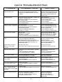
1
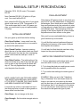
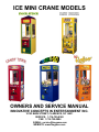
ICE MINI CRANE MODELS
OWNERS AND SERVICE MANUAL
INNOVATIVE CONCEPTS IN ENTERTAINMENT INC.
10123 MAIN STREET, CLARENCE, NY 14031
SERVICE: 1-716-759-0360
FAX: 1-716-759-0884
E-MAIL: [email protected]
WEBSITE: www.icegame.com
1
TABLE OF CONTENTS
INTRODUCTION……………………………….....…...PAGE 3
•
•
GAME FEATURES
GAME PLAY
SET-UP / TESTING / MAINTENANCE…………..…..PAGE 4
•
•
•
•
•
SAFETY PRECAUTIONS
GAME SET-UP
ASSEMBLY
TESTING
CLEANING
PROGRAMMING……………………………………....PAGE 5 - 10
•
•
•
PROGRAMMING MODES
OPTION MODES
ERROR CODES
MANUAL SETUP / PERCENTAGING…………...…...PAGE 11 - 14
•
OVERVIEW
QUICK TROUBLESHOOTING…………….…….....…PAGE 15 & 16
•
PROBLEMS AND SOLUTIONS
GAME REPAIR…………………..…………….………..PAGE 17 - 19
•
•
•
GLASS REPLACEMENT
MECHANICAL REPAIR
ELECTRICAL / ELECTRONIC REPAIR
PARTS LISTINGS……………………………...…........PAGE 20 & 21
SCHEMATICS…………………………………………..PAGE 22 & 23
WIRING DIAGRAMS………………………...…….......PAGE 24 - 41
WARRANTY INFORMATION……….…………….......PAGE 42 & 43
ICEDOC CS9001
REVISION E
11-11-02
2
INTRODUCTION
GAME FEATURES
GAME PLAY
The new MINI CRANE by I.C.E. was designed
with the operator in mind. Reliability, low maintenance, available custom cabinetry, and all
metal exterior construction are some of the most
important design features to be added to the
newest member of our crane family.
As coins are inserted into the MINI CRANE a
coin in sound will be heard. When sufficient
coins have been inserted, the game sound
starts, the claw clicks closed and re-opens,
which signals the start of the game. The crane
will position its self in the middle of the “play
field” and remain there, with the cranes sound
theme playing until the player is ready.
To keep things easy for the operator, all of our
best features have been carried over from our
other designs. Things such as an all-metal exterior, powdered epoxy paint, tempered glass windows, and full-featured programming are standards you’ve come to expect from I.C.E. products.
When the player has moved the joystick or
pressed the buttons, to move the crane, the
timer on the right display will begin to count
down. The player will position the crane above
the prize and they are attempting to win and
press the drop button to lower the claw.
If the nudging option is on, then the player will
have the ability to keep “nudging” the claw down
each time the button is pressed to hone in on
the chosen prize. If the nudging option is off,
then the player will have only one chance to
drop the claw.
The MINI CRANE uses state of the art electronics with a new drive circuit for all motors. In our
new design, even direct short circuits can’t damage the motor or coil drivers. The protection is
built into the drivers themselves! Another advantage is that the new board incorporates modular
driver circuits so the same main board can be
used on multiple products.
When the claw is fully dropped it will close and
retract to its upper most position. The crane will
then automatically position its self over the prize
chute at the rear of the cabinet. The claw will
open, releasing the prize (if grabbed) into the
prize chamber. The player can now remove the
prize from the chamber through the prize door
located in the front, lower left corner of the
game. The game is now in its home position
and is ready for the next player in line.
This crane has been made to give you a crane
that is competitive with other smaller cranes of
its size, but it has been engineered to leave the
competition behind. Every aspect of small crane
design has been scrutinized and improved to
bring it up to the standards necessary to compete in today’s market.
We hope you thoroughly enjoy your ownership
experience with your new MINI CRANE. If you
have any questions or comments, please contact our service department at: (716) 759-0360
3
SET-UP / TESTING / MAINTENANCE
SAFETY PRECAUTIONS
TESTING
After the initial setup, it is time to test your game for
proper operation.
IMPORTANT: FAILURE TO FOLLOW THESE DIRECTIONS CLOSELY COULD CAUSE SERIOUS DAMAGE
TO YOUR GAME.
1. Locate the game in its permanent location.
2. Be sure the game has been properly plugged into
a 3 prong grounded outlet, and that the receptacle is in good working order.
WARNING: WHEN INSTALLING THIS GAME, A 3
PRONG GROUNDED RECEPTACLE MUST BE USED.
FAILURE TO DO SO COULD RESULT IN SERIOUS INJURY TO YOURSELF OR OTHERS. FAILURE TO USE
A GROUNDED RECEPTACLE COULD ALSO CAUSE
IMPROPER GAME OPERATION, OR DAMAGE TO THE
ELECTRONICS.
3. If using an extension cord, be sure it is a 3 prong
grounded type of at least 16Ga.
4. Verify that the game is set up for the proper voltage, and turn the power to the game on.
DO NOT DEFEAT OR REMOVE THE GROUNDING
PRONG ON THE POWER CORD FOR THE SAME REASONS AS GIVEN ABOVE. USING AN IMPROPERLY
GROUNDED GAME COULD VOID YOUR WARRANTY.
5. The game will run through a test mode at every
startup. See test mode explanation in the programming section for details.
GAME SET-UP
7. Check the credit and prize counters for proper
operation.
6. Insert coins/bills into the machine at least ten
times into the coin mech/bill acceptor to assure
proper operation
8. Check game volume during busy time at location
to set it at the proper level.
BEFORE PLUGGING THE GAME IN, OR TURNING IT
ON, BE SURE THE GAME HAS BEEN SET TO THE
PROPER VOLTAGE. YOUR GAME SHOULD COME
PRE-SET FROM THE FACTORY CORRECT VOLTAGE,
HOWEVER IT IS A GOOD IDEA TO CHECK THE A.C.
WALL RECEPTACLE VOLTAGE BEFORE PLUGGING
THE GAME IN.
CLEANING
Regular cleaning of this game will keep it looking new,
and greatly enhance its appeal.
Clean the windows of your MINI CRANE with a standard
window cleaner such as Windex®
ASSEMBLY INSTRUCTIONS
1. Carefully unbox the game from its packaging.
Clean the cabinet sides with a good cleaner such as
“Fantastic” or “409” and a soft rag. A mild soapy solution
can be used. You may use a furniture polish when finished to protect the game and make it look more attractive,
2. Using the supplied keys, unlock the front door of
the cabinet.
3. Cut all tie wraps holding the wagon assembly and
crane in place.
4. Plug the game into a three prong grounded receptacle. NOTE: The appliance must be positioned such that the plug is accessible during use.
NOTE: DO NOT USE ALCOHOL, THINNERS OF ANY KIND,
OR PINBALL PLAY FIELD CLEANERS ON ANY OF THE CABINET SURFACES ESPECIALLY THE DECALS.
5. The game is now ready for start up.
IF YOU HAVE ANY QUESTIONS OR COMMENTS REGARDING INSTALLATION OR PROPER FUNCTION OF YOUR
GAME, PLEASE CALL OUR SERVICE DEPARTMENT AT 1716-759-0360
4
PROGRAMMING
ENTERING THE
PROGRAMMING MODE
100 and 11, at the end of the game option 17 is
set to “1” (on).
To enter the programming mode, open the front
door and press the button marked PROG. Located on the main board housing inside the front
door and the crane will move to the front center
of the game.
MODE "1" GAME MODE
There are two game modes:
Once you are in the programming mode move
the joystick forward and backward or use the
forward button to move through the modes. To
change the value of the mode move the joystick
left and right or use the right button. Once all
options have been set, press the drop button
and the game will return to regular game plat
with the new settings.
−
−
MODE EXPLANATIONS
Normal play – This is the standard type of
play where a player has inserted enough
coins to create 1 credit and then plays the
game. Whether the player wins a prize or
not, the game is over.
Play till win – In this mode the player has
inserted enough coins to create 1 credit and
will be able to play the game until they win a
prize.
MODE "2" TIME
MODE "0" GAME TYPE
This option allows the operator to set the game
play length. Options are from 10 seconds to 60
seconds in 5 second intervals.
– There are 5 game types:
"0" Left, Right, Forward, Backward, Nudge –
This mode is for a control panel that commonly
has a joystick and allows the player to lower the
claw each time the drop button is pressed. This
allows the player to hone in on the prize they
are attempting to win. NOTE: The crane will position it self according to the operator presets,
options 10 and 11, at coin up if option 17 is set
to “0” (off). The crane will position it self according to the operator presets, options 10 and 11,
at the end of the game option 17 is set to
“1” (on).
MODE "3" COIN
This option allows the operator to set the
number of coins needed to create 1 credit. A
setting of “0” will put the game into free play.
MODE "4" BILL
This option allows the operator to set the
number of coins each bill is worth. A setting of
“0” turns this option off.
"1" Left, Right, Forward, Backward, Drop This mode is for a control panel that commonly
has a joystick and the claw drops fully when the
button is pressed. NOTE: The crane will position it self according to the operator presets, options 10 and 11, at coin up if option 17 is set to
“0” (off). The crane will position it self according
to the operator presets, options
5
PROGRAMMING
MODE "5" COUNTER TYPE
MODE "9" AUTO
Setting this option to “0” will have the game
count credits on the mechanical and software
counters. Setting this option to “1” will have the
game count coins.
STRENGTH
This option allows the operator to set the claw
strength for the auto percentaging mode. Available claw strengths are 50-99 with 99 = 100%
claw strength. NOTE: When in auto percentaging mode the claw will, at bottoming, close with
100% strength and will then be backed off to the
number set in this mode. i.e. With this mode set
to 75, the claw will at bottoming close with 100%
strength then back off to 75. NOTE: The claw
will open and close allowing the operator to feel
each strength setting to determine which best
suits their needs. When the correct setting is
determined the operator can just move to the
next option, and the auto strength option is set.
MODE "6" ATTRACT
This option allows the operator to set the number of minutes between attract modes. Available settings are from 1 minute to 30 minutes in
1 minute intervals.
MODE "7" ATTRACT TYPE
MODE "10" RIGHT TIME
This option allows the operator to choose what
type of attract mode they want.
This option allows the operator to adjust the
time the right motor drive will stay on, for centering purposes at game start up. Available settings are 0-40 intervals of ¼ sec. EXAMPLE: If
this option is set at five, then the right drive motor will stay on for (5*¼ sec = 1¼ sec.) 1¼ sec.
This option is used to correctly center the crane
at coin up with different coin speeds and crane
sizes. The operator can also use this option
along with option 17 to adjust the position of the
crane head when the game is over.
“1” will have an attract mode with movement
only.
“2” will have an attract mode with both audio
and movement.
MODE "8" MANUAL
STRENGTH
This allows the operator to set the strength of
the claw for manual percentaging. Available
claw strengths are 50-99 with 99 = 100% claw
strength. NOTE: When in this mode the claw
will open and close with the strength set in this
mode. The operator will be able to feel each
strength setting to determine which best suits
their needs. When the correct strength setting
is determined the operator can just move to the
next option, and the manual strength option is
set.
MODE "11" FORWARD
TIME
This option allows the operator to adjust the
time the forward motor drive will stay on, for
centering purposes at game start up. Available
settings are 0-40 intervals of ¼ sec. EXAMPLE: If this option is set at five, then the forward
drive motor will stay on for (5*¼ sec = 1¼ sec.)
1¼ sec.
6
PROGRAMMING
This option is used to correctly center the crane
at coin up with different coin speeds and crane
sizes. The operator can also use this option
along with option 17 to adjust the position of the
crane head when the game is over.
MODE "15" TICKETS IF
LOSE
This option is used only if you have a ticket dispenser. In this option the operator has the ability to set the number of tickets that a player will
be awarded when a piece of plush is not won.
The available range is 0-99 tickets.
MODE "12" PLUSH COST
MODE "16" FACTORY
DEFAULT
The operator will use this option to detail the
cost of an average piece of plush used in their
crane, in terms of the lowest denominator coin
used to coin up the game. EXAMPLE: If the average cost of a piece of plush is $1.50 and the
lowest denominator coin used to coin up the
game is $0.25 then the number entered for this
option will be 6 ($1.50 / $0.25 = 6). The available plush costs for this option are 1-20.
A setting of “0” for this option will keep the latest operator settings. A setting of “1” for this
option will restore all options to factory defaults.
MODE "17" CENTERING
ON / OFF
MODE "13" PAYOUT
This option allows the operator to position the
crane any where on the play field. If option 17
is set to “0” (Off) the crane head will position its
self at the beginning of the game according to
the operator pre sets in options 10 and 11. If
option 17 is set to “1” (On) the crane head will
position its self at the end of the game according to the operator pre sets in options 10 and
11.
The Operator will input the desired payout for
the auto percentaging mode. The available percentages for this option are 20% - 50%.
MODE "14" TICKETS TO
PLAY
MODE "18" SNAP ON / OFF
This option is used only if you have a ticket dispenser. In this option the operator has the ability to set the number of tickets that a player will
be awarded just for playing the game. The
available range is 0-99 tickets.
This option allows the operator to turn off and
on the snap of the claws at the start of the
game. If option 18 is set to “0” (Off) the claws
will not snap together at the start of a game. If
option 18 is set to “1” (On) the claws will snap
together at the start of a game.
7
PROGRAMMING
Entering the Accounting Mode
MODE "19" CREDIT
DISCOUNTING
To enter the accounting mode, open the front
door and press the button marked ACCOUNT.
Located on the main board housing inside the
front door. The left displays will flash between
“cr” (credits) then the number of credits 1-9999.
If the operator presses the drop button the displays will flash “pl”(plush), then the number of
plush that has passed through the sensor.
These numbers can never be reset and WILL
NOT match the numbers on the mechanical
counters from the counters. It is advisable that
the owner, note this difference so that they will
be able to track actual software coins/credits
and plush out vs. mechanical counters for accounting purposes.
This mode allows the operator to give a free
game for multiple CONSECUTIVE credits. In
other words, if for example you set a "2" for this
option, for every 2 credits IN A ROW that are inserted a free game will be given. The range for
this option is 0-5. Setting a "0" turns this option
OFF.
MODE "20" UP / DOWN
MOTOR TEST
When the operator moves the joystick left and
right the claw will raise and lower respectively.
The display will change from:
0-1 if the up switch is made
0-2 if the down switch is made
0-3 if both switches are made
Test Mode Explanation
Every time that the game is powered up, of the
door is closed, the game will run through a test
mode to check the following items.
-HOME BACK SWITCH
-FRONT/BACK MOTOR
-PRIZE SENSOR
-HOME LEFT SWITCH
-LEFT/RIGHT MOTOR
-OUT OF RANGE
-UP SWITCH
-CREDIT/COIN DISCONNECT
-E² (MEMORY)
-DOWN SWITCH
-CLAW CLOSE, CLAW OPEN
MODE "21" LEFT/RIGHT
MOTOR TEST
When the joystick is moved left and right the
wagon assembly will move to the left and right.
The right display will change from:
0-1 if the left home switch is made
MODE "22" FRONT/BACK
MOTOR TEST
If any of the above items are malfunctioning, the
game will light the 4 decimal points on the podium displays. This will alert the operator that
there has been a problem. The operator needs
only unlock and open the front door and the error codes will be displayed one at a time on the
left display. To move to the next error code the
operator needs to press the drop button. Repairs should be made to those areas in which
errors have been logged. When all codes have
been seen
When the joystick is moved left and right the
wagon assembly will move to the forward and
backwards. The right display will change from:
0-1 if the back home switch is made
8
PROGRAMMING
and the door is closed the game will reset error
codes, run through a test mode to check for
proper operation and if all is well, game play can
start, if the 4 decimals will once again light up,
the operator will need to check the error codes
again. The play can continue to the best of the
machines abilities, with problems, until the errors are corrected. At no time should the game
be inoperable unless a key component is damaged.
Error Codes
#
Error code 10/11 will alert the operator that the
game has paid out 8 too many or 8 too little
pieces pf plush then in auto percentaging. If
this error is logged the game will automatically
revert to MANUAL settings until one of the following options is changed. (COST OF PLUSH,
AUTO % MIN., % PAYOUT, OR GAME COST)
This is why it is imperative that the manual setting be setup before auto percentaging is used.
NOTE: Changing one of these options will reset
error code 10/11 and the game will begin auto
percentaging with the new settings.
NOTE: Some items on the list can not be detected by the game and require that the operator watches for these actions to be performed
during the start up test mode. (Claw close, Claw
open).
9
1
E² (Memory)
2
Prize Sensor
3
Up Sensor
4
Down Sensor
5
Left/Right Sensor
6
Front/Back Sensor
7
Left/Right Motor
8
Front/Back Motor
9
Counter Disconnect
10
Out Of Range (High)
11
Out Of Range (Low)
PROGRAMMING
MODE
DESCRIPTION
(Credit Display)
MIN / MAX / DEF
MEANING
(Timer Display)
BASIC PROGRAMMING
0
Game Type
0, 1, 0
0—Left, Right, Forward, Backward, Nudge
1—Left, Right, Forward, Backward, Drop
1
Game Mode
0, 1, 0
0—Normal Play
1—Play till you win
2
Time
10, 60, 20
10—60 Seconds (Inc. every 5 seconds)
3
Coin
0, 9, 2
0—Free Play
1—9 Coins required for a single credit
4
Bill
0, 9, 4
0—Off
1—9 Number of coins each bill is worth
5
Counter Type
0, 1, 0
0—Credit counter
1—Coin counter
6
Attract
1, 30, 20
1—30 Minutes between attract modes
7
Attract Type
1, 2, 2
1—Motion only
2—Audio and motion
8
Manual Strength
60, 99, 75
40—99 Claw strength Inc. by 1 (99= MAX)
ADVANCED PROGRAMMING
9
Auto Skill Leveling Strength
0, 99, 0
0—Auto off
60—99 Claw strength in auto (99 = MAX)
10
Right Time
0, 9, 5
0—9 Number of 1/4 sec. time intervals right
11
Forward Time
0, 10, 5
0—10 Number of 1/4 sec. time intervals forward
12
Plush Cost
1, 20, 4
Coins per piece of plush
13
Payout
20, 50, 33
20—50 Desired payout percentage
14
Tickets to Play
0, 50, 0
0—50 tickets to be paid just to play game
15
Tickets if Lose
0, 50, 0
0—50 tickets to be paid if you do not win plush
16
Factory Default
0, 1, 0
0—Normal
1—Restore factory defaults upon next startup
17
Center On / Off
0, 1, 0
0—Center option off
1—Center option on
18
Snap On / Off
0, 1, 1
0—Snap option off
1—Snap option on
19
Credit Discounting
0, 5, 0
# of Consecutive credits inserted for 1 free game
20
Up / Down Motor Test
DIAG.
Right display changes: 0 – 1 Up switch is made
0 – 2 Down switch is made
0 – 3 Both switches are made
21
Left / Right Motor Test
DIAG.
Right display changes: 0 – 1 Left switch is made
22
Front / Back Motor Test
DIAG.
Right display changes: 0 – 1 Back switch is made
0 – 2 Front switch is made
10
MANUAL SETUP / PERCENTAGING
OVERVIEW
CLAW OPEN POSITION
Although our crane offers the option of being
able to be set up for MANUAL or AUTOMATIC
PERCENTAGING modes, many operators prefer to use the MANUAL percentaging mode for a
number of reasons.
The CLAW OPEN POSITION is determined by
how you set the adjustable washer that is
located under the solenoid plunger. This should
be adjusted so that the claw will go around one
plush prize, but will not go around more than
one. This is important so you can limit the
payout and more accurately keep track of your
prize count (if you have a prize sensor). It is
especially important to adjust the claw open
position if you use small or beanie type prizes.
If the claw opening is too large, you could pick
up multiple prizes at once very easily.
NOTE: THE FOLLOWING INFORMATION IS
NOT APPLICABLE TO CANDY CRANES.
CANDY CRANES ARE GENERALLY SET UP
AS PAY 'TILL YOU WIN AND ARE NORMALLY SET UP FOR THE SHOVEL OR
SCOOP TO GRAB AS STRONGLY AS
POSSIBLE.
When Manually percentaging your cranes, ALL
of the following factors may affect your payout:
This open position can be easily changed by
ROTATING the "Saw Blade" shaped cam
washer located just under the solenoid plunger.
Loosen the Allen head bolt under the claw
assembly, rotate the washer until the claw open
position what you want, then re-tighten the Allen
bolt.
- Claw open position
- Claw closed position
- Claw Slider positioning
- Claw shape
- Claw Strength
- Size and Texture of the Plush
- Packing of the Plush
- Type of Customer
CLAW CLOSED POSITION
Basic EXPERIENCE and EXPERIMENTATION
will determine the best set-up for you. Our
cranes offer all of the popular adjustment options, so you can easily set your crane up to
work just as any other cranes you may have
previously used.
The CLAW CLOSED POSITION is important for
determining the OVERALL grab or
"appearance" of grab of the claw. Normally, the
claw closed position is set so that when the
solenoid in engaged, the claw appears to close
fully. For the most part, the prizes are big
enough that the tips of the claw can be set up to
be slightly apart when the solenoid is energized.
Normally you do not want the tips to bang
together as they can lock into each other if they
overlap too far, then even when the solenoid
releases, the claw tips are stuck together. For
this reason we generally recommend that you
keep about a "dime" sized space between the
claws when they are closed. Of course you can
also adjust this opening size to anything you
would like.
The above mentioned factors are described in
greater detail below. We will review all of these
in detail, so you will know better how to set up
your game.
NOTE: IF YOU ALREADY KNOW HOW ALL
OF THE ABOVE MENTIONED FACTORS
AFFECT YOUR EARNINGS, YOU MAY
PROCEED TO THE SETUP SECTION.
To adjust the claw closed position, loosen the
bottom collar on the solenoid housing, and raise
11
MANUAL SETUP / PERCENTAGING
or lower the position of the collar to adjust the
closed position of the claws. Push the solenoid
plunger in by hand to verify the claw position
and re-tighten the collar.
NOTE: THIS ADJUSTMENT HAS THE MOST
IMPACT ON YOUR PERCENTAGING.
ALLOWING THE SLIDER MORE OR LESS
MOVEMENT WILL CHANGE YOUR OVERALL
PAYOUT PERCENTAGE.
Play around with the upper collar positioning to
get an idea of how this adjustment works.
CLAW SLIDER POSITIONING
The job of the CLAW SLIDER is to determine
the ACTUAL grab of the claw. This actual grab
however, will change based on where the claw
contacts the plush. This change is what actually
makes the game exciting to the customers and
allows for more challenging game play.
CLAW SHAPE
CLAW SHAPE will determine how easily the
plush is grabbed. A rounder shape will "cradle"
the plush more making it easier to pick up plush.
You will want to use this shape (see illustration)
if you have large or heavy plush and are having
a difficult time dispensing enough product.
The slider will move up and allow the claw to
open whenever there is lateral (side to side)
pressure exerted on the claw tips. When the
pressure is removed the claw instantly returns
to the closed position.
On the other hand, if the game consistently
pays out too much, you may wish to change the
shape of the claw if none of your other adjustments will percentage the game properly. You
will want to bend the claws into more of a
"HEART" shape. (See illustration) This will allow
the plush to slide more easily through the claws.
Since the lateral (side to side) pressure against
the claw tips is what allows the slider to function, the shape of the claw will influence how
easily the slider will work. (For more on claw
shape, read the claw shape section of the
manual).
CLAW STRENGTH
The claw slider is adjusted by the position of the
upper collar on the solenoid body. If you set the
collar against the slider, it will not function at all.
This effectively locks the slider out. This is
"usually" what is done for the auto-percentaging
mode.
CLAW STRENGTH can also be used to fine
tune your payout percentages. By increasing
claw strength from lowest power (40) to (99)
highest you can adjust the strength of the solenoid. You will normally want to keep your claw
strength between 80-99 unless you are using
very light prizes.
If the collar is adjusted for a larger gap, the claw
will open further. The bigger the gap, the more
the claw grab is actually limited.
SIZE AND TEXTURE OF PLUSH
You may wish to adjust the slider so that a grab
of an arm, leg or hand will not work, but a grab
of the body will.
The size and texture of plush will had a dramatic
impact on how your game pays out.
You may wish to set the slider so that even a
body grab won't work, but a grab across the
body and shoulder will.
Under normal circumstances, the closer you can
keep the prizes to having the same general size
and weight, the easier it will be to get consistent
payouts. While it is sometimes necessary to mix
12
MANUAL SETUP / PERCENTAGING
CALCULATIONS
different size prizes, please be aware that this
will affect your payout to some extent.
The best way to set up your crane manually is
to test it in house over a number of games.
The biggest issue with plush size will be adjusting the slider to compensate for the different
sizes.
We suggest testing in 100 game increments to
get the best idea of an accurate payout. Once
you become familiar with your crane and your
prizes, you may not need to test as extensively
in house. Of course, you could bypass this entire step, but you might get undesirable results
in the field.
Texture of the plush can affect payouts as well.
Vinyl toys will stick and grab the claws differently than fur covered toys that will slide through
more easily.
PACKING OF THE PLUSH
Use the following example to figure out your
PAYOUT using the following example.
How you "pack" the plush will have a big impact
on how your game pays out. Some people prefer to tightly pack the plush to keep the payout
lower. This works fine until a few prizes are won
and then it becomes much easier to win. We
suggest a loose pack as it is much easier to be
consistent with, and much easier to percentage.
Let's say your game costs 50 cents to play, you
want to pay out 33 percent, and your plush cost
is $2.50.
First, if you play 100 games at 50 cents you
need to figure out what is 33 percent of 100
games at 50 cents.
TYPE OF CUSTOMER
Calculate 100 X .50 (50 cents). This equals
$50.00.
Lastly, don't forget the type of customer at your
location will be a determining factor. You may
need to make adjustments just for this.
Next Calculate $50.00 X .33 which is 33 percent. Your result will be $16.50.
SETTING UP YOUR MACHINE
MANUALLY
Next, divide the $16.50 by the value of your
plush which in this case is $2.50. The answer is
6.6 This would mean that for each 100 games
you play, you would want to pay out approximately 6.6 prizes.
PLEASE READ THIS SECTION CAREFULLY
TO GET THE BEST POSSIBLE RESULTS
FROM YOUR MACHINE
Let's do the same calculations again with different beginning values…
In this section we will give you an example of
how you might like to set your machine up.
Let's say your game costs 25 cents to play, you
want to pay out 20 percent, and your plush cost
is $1.50
As you become more familiar with this machine,
you may be able to eliminate some steps.
First, if you play 100 games at 25 cents you
need to figure out what is 20 percent of 100
games at 25 cents.
13
MANUAL SETUP / PERCENTAGING
Calculate 100 X .25 (25 cents). This equals
$25.00.
FINAL ADJUSTMENT
Next Calculate $25.00 X .20 which is 20 percent. Your result will be $5.00
After playing 100 games check to see what your
payout is at. Use the adjustments to change the
percentages. Since there are so many different
ways and preferences by the customers to raise
or lower payouts, please feel free to experiment
with different ways. The information at the beginning of this section details all of the possible
adjustments and their affects on the game.
Next, divide the $5.00 by the value of your plush
which in this case is $1.50. The answer is 3.3
This would mean that for each 100 games you
play, you would want to pay out approximately
3.3 prizes.
INITIAL ADJUSTMENT
Set your game up as follows before testing:
Retry until you are comfortable that you have a
good initial set-up for the street.
Claw Open Position - Leave stock from the
factory unless the open position is too small to
go around the plush prizes.
You will find that various locations will payout
differently just because of the types of players
that frequent the locations.
Claw Closed Position - Leave an opening
about the size of a dime when claws are closed.
This will prevent the claw tips from overlapping
which could cause the claw tips to stick together.
You will also find that the plush can have a big
impact on the payout percentages.
Claw Slider Position - The initial setting of the
slider should be set so that if the claw tips grab
onto an arm or leg of the plush the claws will
slip off. This only applies when the tips grab
onto the plush from the side.
1. Find an adjustment method that works good
and stick with it for all of your ICE cranes.
HINTS FOR CONSISTENT PAYOUTS
2. Try to keep the plush size and type as consistent as possible within the machine.
3. Try to write down settings for certain types of
plush.
EXAMPLE: When you put in the "Valentines
Day or Christmas" mix, write down those settings so you can set your crane up the same
way the next time you put that particular mix into
the machine. Also, if you have a lot of locations,
you can just tell your route man how to set up
the cranes for that particular type of plush.
NOTE: WHEN THE CLAW TIPS ARE UNDER
THE PRIZE THE SLIDER WILL HAVE VERY
LITTLE EFFECT UNLESS THE CLAW SHAPE
HAS BEEN CHANGES NOTICEABLY.
Loosen the top collar or cap located on top of
the slider and raise or lower to allow greater or
lesser effect from the slider.
Claw Shape - do not change at this time.
Claw Strength - Set the initial strength value to
"70"
14
QUICK TROUBLESHOOTING
PROBLEM
PROBABLE CAUSE
SOLUTION
THE DECIMALS ON THE 4
DISPLAYS ARE LIT UP
THIS IS IN FACT NOT A PROBLEM BUT A WAY
OF LETTING THE OPERATOR KNOW THAT
THERE WAS A PROBLEM DURING THE START
UP MODE
OPEN THE FRONT DOOR AND THE
ERROR CODES ARE SHOWN ON THE
DISPLAYS. TO ADVANCE THROUGH
THE ERROR CODES, PRESS THE
FIRE BUTTON
NO GAME POWER
ON-OFF SWITCH ON THE GAME IS TURNED OFF
BLOWN A.C. POWER FUSE
GAME NOT PLUGGED OR CORD DAMAGED
BAD TRANSFORMER
TRANSFORMER HARNESS NOT CONNECTED
BAD POWER MODULE
TURN POWER ON
REPLACE WITH PROPER FUSE
CHECK POWER CORD
CHECK FOR PROPER VOLTAGES
CHECK HARNESS
REPLACE POWER MODULE
GAME WILL NOT TAKE MONEY BAD COIN SWITCH
OR GIVE CREDITS CORRECTLY COIN DISCOUNTING SET WRONG
COINS PER CREDIT SETTING INCORRECT
BAD COIN MECHANISM
LOOSE OR DAMAGED HARNESSING
BAD MAIN P.C. BOARD
CHECK W/METER AND REPLACE
CHECK PROGRAMMABLE SETTING
CHECK PROGRAMMABLE SETTING
ADJUST OR REPLACE
CHECK W/METER—REPAIR
REPAIR OR REPLACE MAIN BOARD
DISPLAYS DO NOT WORK
BAD 12V FUSE
BAD DISPLAY P.C. BOARD
BAD MAIN P.C. BOARD
LOOSE OR DAMAGED DISPLAY HARNESSING
REPLACE WITH PROPER FUSE
REPAIR OR REPLACE P.C. BOARD
REPAIR OR REPLACE P.C. BOARD
CHECK W / METER AND REPAIR
CRANE OR WAGON DOES NOT
MOVE
BAD MOTOR
LOOSE OR DAMAGED HARNESSING
BAD SWITCH ON BUTTON OR JOYSTICK
BAD HARNESSING TO BUTTONS OR JOYSTICK
BLOWN FUSE TO MOTORS ON MAIN P.C.B.
BROKEN DRIVE BELT
REPLACE MOTOR
CHECK W / METER—REPAIR
REPLACE SWITCH
CHECK W / METER—REPAIR
REPLACE WITH PROPER FUSE
REPLACE BROKEN BELT
CRANE KEEPS TRYING TO
MOVE IN TO THE HOME
POSITION
BAD LIMIT SWITCH (S)
LIMIT SWITCH NOT ALIGNED WITH ACTUATOR
REPLACE SWITCH(S)
ALIGN SWITCH AND ACTUATOR
CLAW WILL NOT CLOSE
BLOWN FUSE TO CLAW ON MAIN P.C. BOARD
BAD COIL
LOOSE OR DAMAGED HARNESSING
CLAW HAS MECHANICALLY JAMMED
REPLACE WITH PROPER FUSE
REPLACE COIL
CHECK W / METER AND REPAIR
FIND JAM AND REPAIR
CLAW STAYS CLOSED
BAD DRIVE TRANSISTOR ON MAIN P.C.B.
CLAW HAS MECHANICALLY LOCKED
REPLACE TRANSISTOR
FIND JAM AND REPAIR
AUTO PERCENTAGING IS NOT
FUNCTIONING
PROGRAMMING IS NOT CORRECTLY SET
BAD PRIZE SENSOR
LOOSE OR DAMAGED SENSOR HARNESS
SET OPTIONS “9” AND “16”
REPLACE PRIZE SENSOR
CHECK W / METER AND REPAIR
CLAW GOES DOWN AND THEN
UP BUT DOES NOT CLOSE
DOWN SWITCH BAD
LOOSE OR DAMAGED HARNESS TO DOWN
SWITCH
REPLACE DOWN SWITCH
CHECK W / METER AND REPLACE
CLAW COMES UP AND ABOUT
15 SEC. PASSES BEFORE
CRANE MOVES TO THE HOME
POSITION
UP SWITCH BAD
LOOSE OR DAMAGED HARNESS TO UP SWITCH
REPLACE UP SWITCH
CHECK W / METER AND REPLACE
CRANE OR WAGON WHEELS
SLIP
MISSING OR DAMAGED O-RING DRIVE BELTS
LOOSE SET SCREWS IN WHEELS
LOOSE SET SCREWS IN DRIVE COUPLER
RAILS NEED TO BE SCUFFED
REPLACE O-RING BELTS
TIGHTEN SET SCREWS
TIGHTEN SET SCREWS
SCUFF TOP OF RAILS WITH
SANDPAPER
15
QUICK TROUBLESHOOTING
1.
A self-test will be performed each time the front door is “closed” or the game is powered up.
2. If the Wagon does not move smoothly through a full travel from left to right, check to see that the
wheel spacing is correct. If the spacing is correct then check the 2 cabinet rails for burrs that may
cause the wheels to bind. Also check for broken or loose drive belts.
3. If the Wagon does not move smoothly through a full travel from front to back, check to see that the rod
bushings are straight and not binding. Check for excessively loose drive belts or one of them broken.
4. If the front door is having trouble closing fully, check to see that the front door harness is routed properly. Also be sure the prize door is fully shut. If it is partially open it will not allow the front door to open
or close properly.
5. If the door will not lock properly or locks with difficulty, check to see if the lock rotates smoothly. Next
check that the lock rods are not binding on the lock cam or the lock rod guides. Next check that all
friction points have been lubricated with molly grease. Finally if need be, file the lock rod guides such
that the door closes and locks smoothly but be careful not to file out too much, for this may cause the
door not to pull tightly to the cabinet as it was intended to do.
6. If the decimals light up on the displays after a self-test, an error has been locked. To advance through
the error codes press the drop button when in error detection mode.
7. If, at the beginning of the self-test mode, the claw does not drop, one or more of the following may apply. The prize sensor is not working, or blocked. The string or string lever is mechanically binding.
The up or down switch is sticking or misaligned from its actuator.
8. If claw stays closed it is likely that the diode has blown and the transistor controlling the claw has also
blown. Shut off the game immediately and have a new diode, in coil assembly, and transistor, on
main board, installed.
9. If claw is jerky while being lowered, it is likely that the string has mechanically bound on the spool. To
fix the string binding enter programming mode and go to CLAW UP/DOWN MODE. By moving the
joystick to the left and right you are able to raise and lower the claw mechanism. Move the crane over
the prize chute and lower the claw mechanism all the way until it starts to wind up backwards. Reverse the motor direction to raise the claw mechanism and properly rewind the string on the spool.
Exit the programming mode and the string should be free of mechanical binding.
10. If the claw stays open First check for bad fuses on the main board, next check that there are no wires
dislodged from the connectors in the harness between the wagon and the crane, the harness between
the wagon and the main board, the crane assembly and the wagon assembly. If the problem still exists and no fuses are blown or wires dislodged it is likely that the transistor controlling the voltage to
the claw has blown on the main board. Replace main board and have the other main board repaired
by electronics.
11. If the crane/wagon in the home position still tries to move left or back, check to see that the actuators
are both present. Check to see that the sensors are present. Next check to see that the sensors and
the actuators are both aligned. Then check to see that the sensor wires are not dislodged from the
connectors. Finally replace the sensor; it is likely to be bad.
16
GAME REPAIR
WARNING: ALWAYS REMOVE POWER TO
THE GAME BEFORE ATTEMPTING ANY
SERVICE, UNLESS NEEDED FOR SPECIFIC
TESTING. FAILURE TO OBSERVE THIS
PRECAUTION COULD RESULT IN SERIOUS
INJURY TO YOURSELF OR OTHERS.
GLASS
REPLACEMENT
1. Remove all A.C power from the game.
2. Open the front door and unscrew the brackets that retain the glass.
TROUBLESHOOTING
PHILOSOPHY
3. Carefully remove all broken glass from the
game. Vacuum up any remaining pieces.
4. Carefully install the new glass and replace
the mounting brackets.
To find problems with this game, always first check
what should be obvious. See that the game is
plugged in, and all of the fuses on the game are
good.
REMOVAL OF CRANE
MECHANISM
Next, check to see that all of the connectors are
firmly seated, and that none of the wires have pulled
out of them.
1. Remove all A.C. power from the game.
2. Unlock and open the front door.
When trying to find out if specific components are
bad or not, try swapping them with components from
another player station to see if the problem moves
with the component, or stays where it was. This will
help you to know if you have a problem with a specific component, or maybe a problem with either the
wiring or the Main P.C. Board. Use extreme caution
when using probes or voltmeters if the game is powered up. If checking continuity, it is important to disconnect the harnessing at both ends, as attached
they may yield erroneous results.
3. Slide the crane assembly to the front center
of the machine for access to the micro track.
4. Pull down on the micro track and pull away
from the Crane. This will unlock the micro
track from its mounting bracket.
5. Disconnect the connector from the crane assembly.
6. Carefully lift the entire crane assembly off the
rails approximately 2 inches, rotate clockwise
as far as possible, and drop past the crane
rail and remove the entire assembly out from
the game.
If P.C. Boards are suspected as causing problems,
check to see that all I.C. chips are firmly seated on
the boards.
7. Reassemble in reverse order.
MAIN P.C. BOARD
REPLACEMENT
STRING REPLACEMENT
1. Remove all A.C. power from the game.
1. Remove all A.C. power from the game.
2. Unlock and open the front door.
2. Unlock and open the front door.
3. Carefully remove all of the connectors from
the P.C. Board.
3. Remove crane assembly as detailed above.
4. Pull the string out a bit and remove from the
spool. Remove the coil cap from the claw coil
and remove the other end of the string.
4. Remove the 4 long plastic hexagon nuts that
secure the board to the main board housing.
5. Gently pull the P.C. Board from the mounting
studs.
6.
5. Take the replacement string and feed up
through the bottom hole in the crane assembly.
Reassemble in the reverse order using a
new main P.C. Board.
17
GAME REPAIR
6. NOTE: STRING PURCHASED FROM I.C.E.
WILL HAVE GLUE ON THE LAST 2 INCHES
TO MAKE IT EASIER TO FEED UP INTO
THE MECHANISM. IF YOU ARE USING
YOUR OWN STRING, WE WOULD SUGGEST YOU GLUE THE END AND LET IT
DRY SO THE END OF THE STRING IS
STIFF.
tor. NOTE: Be sure to note which wire goes
to which motor lead. If they are reinstalled
backwards the motor will run the opposite of
its intended direction.
6. Remove the 3 bolts securing the motor to the
housing.
7. Carefully remove the bad motor.
8. Reassemble in reverse order using new motor. NOTE: When motor is completely reinstalled, place one drop of thread lock on
each of the 4 bolts that secure the motor in
place to prevent the bolts from backing out.
FUSE REPLACEMENT
CAUTION FOR CONTINUED PROTECTION
AGAINST RISK OF FIRE, REPLACE ONLY WITH
THE SAME TYPE OF FUSE HAVING THE SAME
ELECTRICAL RATING.
7. Using a tweezers or suitable tool, grasp the
string and route it through the small pulley
wheels as shown in the photograph above.
LOCATION
AREA
MAIN BOARD
F2
F3
F4
F5
POWER MOD
--
8. Pull the string up and through the hole in the
spool to secure. Tie a knot. Secure the knot
with a small amount of glue and cut off any
excess string.
9. Feed the other end of the string through the
coil cap, knot and secure with a small
amount of glue. BE SURE THE STRING
CAN NOT PULL THROUGH THE HOLE.
AMP VOLT
6 MDQ 250
3 MDQ 250
4 MDQ 250
4 MDQ 250
3 MDQ 250
BULB
REPLACEMENT
10. Reposition the coil cap on the coil and adjust
1. Remove all A.C. power from game.
so the slider on the coil works properly.
Tighten the Allen screw.
2. Unlock and open front door.
3. Remove the clear plastic clip that holds the
bulb into the bulb holder.
CRANE MOTOR
REPLACEMENT
4. Unsnap the bulb from the bulb holder. This
can be done by pushing on the release button while pulling on the bulb.
1. Remove all A.C. power from the game.
5. Replace in reverse order.
2. Unlock and open the front door.
6. Be sure the bulb is snapped securely in
place.
3. Remove crane assembly. (See previous instructions)
7. Snap the clear plastic bulb retainer back into
place.
4. Remove any drive o-rings and pulley wheels
from the bad motor.
5. Unsolder the motor leads from the bad mo-
18
GAME REPAIR
PRIZE FENCE
REPLACEMENT
1. Remove all A.C. power from the game.
2. Unlock and open the front door.
3. Carefully unbolt the 3 bolts and 2 screws
holding the prize fence to the play field.
4. Remove the old prize fence.
5. Assemble in reverse order.
PRIZE SENSOR
REPLACEMENT
1.
Remove all A.C. power from the game.
2. Unlock and open the front door.
3. Remove the cover to the prize chute to access the sensor.
4. Remove the 2 plastic hex spacers securing
the sensor board to the bracket.
5. Carefully remove the sensor board from its
mounting studs.
6. Reassemble in reverse order using a new
prize sensor board.
19
PARTS LISTINGS
CS3040
CS3041
CS3042
CS4001
CS4002
CS4003
CS4004
FP1004
FP2007
HH1006
HR1019
MECHANICAL PARTS
655
655S
4006
5006
5101x
1030
2033X
2089X
2133CR
2133CW
2133U
2134
6324
6356
6364
6365
BC1018
CG1078A
CG2014
CG3036
CG5014
CG5015
CH1052
CH3002F
CP2090X
CS1006
CS1020
CS2021
CS1034
CS1035
CS1036
CS1037
CS1050
CS1058
CS1059
CS1066
CS1070
CS3004
CS3005
CS3008A
CS3008B
CS3008C
CS3008D
CS3013
CS3025
CS3026
CS3027
CS3028
CS3030
CS3031
CS3032
CS3037
CS3039
Square Drive Screw, Black 3/4"
Square Drive Screw, Silver 5/8"
Foam Weather-stripping
Cash Box
Coin Mech Holder
Dollar Bill Validator Cover Plate
Rope Light Controller
AC Rope Light
Rope Light, Red / Chase
Rope Light, Clear / Chase
Rope Light "U" Channel
Rope Light End Cap
#6-32 Acorn Nut
Hex Spacer, Aluminum 2-56 x 3/8"
Plastic Glides
Mirror Clip
Podium
Claw
4 way Joystick w/Push Button
Claw/Coil Interconnects
"T" Lock, 90 deg. swing
"T" lock - Lock Barrel
Rare Earth Magnet
Magnet Enclosure
Harness, Rope Light "Y" Splitter
Door Assembly
Candy Jaw
Jaw Bracket
Clip Holder
Clip Spacer
Adjusting Clip
Switch Trigger
Drive Pulley, Motor
Wagon Drive Shaft
Candy Jaw Shaft
Spring
Coil Housing
Prize Fence
Prize Chute
IGUS Micro Track 42 Link Section
IGUS Mounting Link w/modified end
IGUS Mounting Link
IGUS Quick Connect Mounting Link
Coin Slide
Prize Sensor Mirror
Rear Mirror
Door Glass
Side Glass
Guide Pulley, Shaft
O-ring Retainer
String Spool
Claw Spider
Coil Cap
Guide Pulley, Idler
Drive Pulley, Idler
String Guide
O-Ring, Large Urethane
O-Ring, Medium Urethane
O-Ring, Small Urethane
String
Foot Mounting Plate
4" Speaker
Cash Box Lid
Leveling Feet, 1-1/2”
ELECTRONIC / ELECTRICAL
8312
8422
8452
BC2032X
BW2017
BW2018
CS2008
CS2009X
CG2012
CS2002X
CS2007X
CS2027
CS2034X
CS2039X
CS2050X
CS2052AX
CS2053X
CS2054X
CS8449X
PP250X
20
PLL Fluorescent Light Bulb, 40 watt
Sub-miniature Micro Switch
Micro Switch, Standard Size - Basic
Display P.C. Board Assembly
Bulb Retainer Clip
Light Bulb Retainer
Globe Motor DC 24 volt
Solenoid Coil Sub Assembly
Hamlin Reed Switch
Transformer
Power Module Assembly
20FT. Power Cord
Main P.C. Board
Prize Sensor Opto P.C. Board
Door Harness
Harness Assembly, Upper
Wagon / Crane Harness
Display Harness
Fluorescent Light Ballast, Work Horse 3
Light Bulb Socket, PLL
PARTS LISTINGS
LIL’ PLUSH CRANE
GRAPHICS
7028
7044
CS7205
CS7206
CS7509
CS7510
CS7512
CS7527
Serial Number Decal
Tempered Glass Warning Decal
SNACK ATTACK CRANE
CS7007
CS7012
CS7027
ICE Logo
Control Panel
Front Marquee
LIL’ RODEO CRANE
CS7600
CS7602
CS7603
CS7606
CS7607
CS7608
CS7609
CS7610
CS7612
CS7627
CANDY TOWN CRANE
CS7100
CS7102
CS7106
CS7107
CS7109
CS7110
CS7112
CS7127
Cabinet Side
Side Marquee
Prize Door
ICE Logo
Next to front marquee Decal, left
Next to front marquee Decal, Right
Control Panel
Front Marquee
Cabinet Side
Side Marquee
Front Panel
Prize Door
ICE Logo
Mirror Decal
Next to front marquee decal, Boy
Next to front marquee decal, Girl
Control Panel
Front Marquee
GRAB - N - GO
GG7001
GG7002
GG7012
GG7026
GG7027
LC7001
CANDY FACTORY CRANE
CS7200
CS7201
CS7202
CS7203
CS7204
CS7205
CS7207
CS7208
CS7209
CS7212
CS7227
Side Marquee
Prize Door
Next to front marquee, Left
Next to front marquee, Right
Control Panel
Front Marquee
Cabinet side, Left
Cabinet side, Right
Side Marquee
Lower Front Panel
Front door left strip
Front door right strip
ICE Logo
Mirror Decal
Next to front marquee decal
Control Panel
Front Marquee
21
Prize Door
ICE Logo
Control Panel
Side Marquee (2 per game)
Front Marquee
Side Window Strips (4 per game)
22
23
24
A
B
C
D
3
4
white
4
2
1
green
red
black
WRAP END OF CORD JACKET WITH 1" OF
#8069 - SPIRAL WRAP 1/4" BLACK WERE
PLUG CLAMPS THE CORD
#2960 - PLUG (274-001)
VANCO CBC4MX
4
3
red
white
black
green
DATE
2
1
2
7/9/01
REVISED
2/6/02
#CS2057X - SOLENOID CABLE HARNESS
1
PAGE
DRAWN BY
FILENAME
1 OF 16
MMARTIN
CS.VSD
#CS2009 - SOLENOID,
GUARDIAN
LT8X16-C-12
#CS2009X - SOLENOID
ASSEMBLY
#8497- 2 PIN MOLEX
MICRO-FIT RECEPTACLE
#8496 - MOLEX MICROFIT FEMALE TERMINAL
SNACK ATTACKER
1
2
1
* CUT SOLENOID WIRES TO 1-1/2"
#2163 - DIODE 1N4004
COVER DIODE WITH 1" OF #8380 SHRINK TUBE 1/8" (CLEAR) FIT
#CS2009X - CLAW SOLENOID ASSEMBLY
#8498 - 2 PIN MOLEX
MICRO-FIT PLUG
#8495 - MOLEX
MICRO-FIT MALE
TERMINAL
red + white
black + green
2
DESCRIPTION
TITLE
* NOTE PUT WIRES THROUGH SOLENOID
CAP BEFORE PLUGGING WIRES
2" OF #2611 - SHRINK TUBE FIT 221-1/4"
AND
1 - #351 - CABLE TIE 50# BLK 15-1/2" T50
ON END OF RETRACTABLE CORD:
#8459 - CABLE
RETRACTABLE 4 COND, 7"
* STRIP BACK JACKET 1"
green
black
red
white
* STRIP JACKET BACK 1"
#CS2057X - SOLENOID CABLE
HARNESS
3
A
B
C
D
25
A
B
4
3
#CG2012 - SENSOR
(HAMLIN 59145-010)
DATE
2
DESCRIPTION
TITLE
2 PIN PLUG #2103
SOLID PIN #2100S
1
2
SNACK ATTACKER
7/9/01
REVISED
#CS2012X - SENSOR ASSEMBLY
black
black
2/6/02
1
PAGE
DRAWN BY
FILENAME
CS.VSD
2 OF 16
MMARTIN
A
B
C
1
C
2
D
3
D
4
26
A
B
C
D
DATE
DESCRIPTION
TITLE
7/9/01
4
REVISED
2/6/02
SNACK ATTACKER
GREEN/YELLOW
#2513
2 PIN PLUG #2103
SOLID PIN #2100S
1
2
BLACK
WHITE
15 PIN PLUG #2144
SPLIT PIN #2100
white/black
white/brown
white/orange
white/red
white/yellow
black/brown
black
black
black/white
yellow
red/gray
brown/gray
orange
13 "
AC L
AC N
1
2
3
4
5
6
7
8
9
10
11
12
13
14
15
P9
#CS2050X - DOOR HARNESS
#PC20217
To Transformer
JOY UP
JOY DOWN
JOY RIGHT
JOY LEFT
BUTTON
COIN 1
GND
GND
GND
DBV
SPEAKER +
SPEAKER +12 VDC
4
PAGE
DRAWN BY
FILENAME
2 " STRIP
3
3 OF 16
MMARTIN
CS.VSD
#650
.110
Coin
Lamps
#2874 - 3 con SJO
73 "
#650
.110
26-1/2 "
51 "
57-1/2 "
46 "
57-1/2 "
61 "
58 "
59-1/2 "
58-1/2 "
3
56 "
#653T
.250
#650
.110
#651
.187
2
2 " STRIP
yellow
45-1/2 "
46 "
33 "
Speaker
2
#2513
#650
.110
#653T
.250
#650
.110
#639
.250
WHITE
16 "
5"
4"
4"
4"
.250 #653T
BLACK
yellow
black/white
COIN
GREEN/YELLOW
9-PIN MINI CAP #2568
MALE MINI PIN 8 #2569
20-16 AWG MALE MINI #8162
17-1/2 "
19 "
28 "
35 "
.250 #653T
.250 FLAG
#648
.250 FLAG
#648
.250 FLAG
#648
.250 FLAG
#648
1
2
3
4
5
6
7
8
9
.250 FLAG
#648
.250 FLAG
#648
.250 FLAG
#648
.250 FLAG
#648
.250 FLAG
#648
1
#PC20217
AC L
DBV
GND
AC N
COIN
Joystick
Ground
LEFT
DOWN
To
Joystick
.250 FLAG
#648
BUTTON
RIGHT
UP
1
A
B
C
D
27
#653T
.250
RED (600V) #8446
55 "
M
#654
.250
A
B
4
To PLL Socket
#653T
.250
3
53 "
DATE
2
DESCRIPTION
TITLE
* Twist together at 55" cut back
2 " of Yellow on female side
YELLOW (600V) #8447
7/9/01
HARNESS
REVISED
#CS2051X - BALLAST EXTENTION
2/6/02
1
PAGE
DRAWN BY
FILENAME
To Ballast
SNACK ATTACKER
#654
M
.250
CS.VSD
4 OF 16
MMARTIN
A
B
C
1
C
2
D
3
D
4
28
A
B
C
D
4
CRANE FWD SW
CRANE BACK SW
CLAW DOWN SW
CLAW UP SW
COMMON
FRONT/BACK MOTOR +
FRONT/BACK MOTOR LEFT/RIGHT MOTOR +
LEFT/RIGHT MOTOR UP/DOWN MOTOR +
UP/DOWN MOTOR SOLENOID - (PIN 1)
SOLENOID + (PIN 2)
COMMON
EARTH GROUND
4
1
2
3
4
5
6
7
8
9
10
11
12
13
14
15
15 PIN PLUG #2144
SPLIT PIN #2100
black (flex)
red (flex)
orange (flex)
yellow (flex)
green (flex)
violet (flex)
white (flex)
black (flex)
red (flex)
orange (flex)
yellow (flex)
green (flex)
violet (flex)
white (flex)
green/yellow
FLEX
END
3
3
TRACK
31 "
DATE
2
DESCRIPTION
TITLE
2
1
2
3
4
5
6
7
8
9
10
11
12
13
14
15
7/9/01
HARNESS
#652
REVISED
2/6/02
1
PAGE
DRAWN BY
FILENAME
To Frame
5 OF 16
MMARTIN
CS.VSD
CRANE FWD SW
CRANE BACK SW
CLAW DOWN SW
CLAW UP SW
COMMON
FRONT/BACK MOTOR +
FRONT/BACK MOTOR LEFT/RIGHT MOTOR +
LEFT/RIGHT MOTOR UP/DOWN MOTOR +
UP/DOWN MOTOR SOLENOID - (PIN 1)
SOLENOID + (PIN 2)
COMMON
SNACK ATTACKER
green/yellow
36 "
15 PIN CAP #2367
FEMALE PIN #2102
black (flex)
red (flex)
orange (flex)
yellow (flex)
green (flex)
violet (flex)
white (flex)
black (flex)
red (flex)
orange (flex)
yellow (flex)
green (flex)
violet (flex)
white (flex)
#CS2052AX - MAIN TO WAGON UPPER
RIGID
END
1
A
B
C
D
29
A
B
C
D
4
Home Sw
Gnd
To Sensor
Asssembly
Crane Fwd Sw
Crane Back Sw
Claw Dwn Sw
Claw Up Sw
Gnd
Front/Back Motor +
Front/Back Motor Left/Right Motor +
Left/Right Motor Up/Down Motor +
Up/Down Motor Solenoid Solenoid +
Gnd
To Wagon/Crane
Harness
4
1
2
1
2
3
4
5
6
7
8
9
10
11
12
13
14
15
2 PIN CAP #2181
FEMALE PIN
#2102
pink
black
15 PIN PLUG #2144
SPLIT PIN #2100
red
white
green
brown
black
YELLOW
BLUE
ORANGE
GREEN
BROWN
RED
* BROWN
* BLUE
blue
93 "
3
25 "
#2997 - 2 CONDUCTOR POWER CORD
3
DATE
2
DESCRIPTION
TITLE
2
7/9/01
REVISED
2/6/02
SNACK ATTACKER
#CS2052X - MAIN/WAGON LOWER
HARNESS
red
5 PIN AMP HOUSING #2419
CONTACT PIN #2201
95 "
15 PIN PLUG #2144
SPLIT PIN #2100
BROWN
RED
pink
brown
green
* BROWN
black
black + blue
ORANGE
YELLOW
white
GREEN
BLUE
* BLUE
PAGE
DRAWN BY
1
To Main Board
MotUp
MotDn
HomeL/R
ClawUp
ClawDn
Claw Gnd
Gnd
MotRight
MotBack
HomeF/B
MotLeft
MotFwd
Claw +
36V
To Main Board
6 OF 16
MMARTIN
CS.VSD
Crane Fwd Sw
FILENAME
1
2
3
4
5
PX4
1
2
3
4
5
6
7
8
9
10
11
12
13
14
15
P1
1
A
B
C
D
30
A
B
C
D
DATE
DESCRIPTION
TITLE
#PC20217
7/9/01
4
REVISED
(Part of CS1055X WAGON)
#CS2053X - WAGON HARNESS
2/6/02
SNACK ATTACKER
#PC20217
4-1/2 "
PAGE
DRAWN BY
3
3
7 OF 16
MMARTIN
CS.VSD
34-1/2 "
FILENAME
green/yellow
green/yellow
15 PIN CAP #2367
FEMALE PIN #2102
violet
black (existing)
black (flex)
red (flex)
orange (flex)
blue
blue/white
green
green/white
yellow (flex)
green (flex)
violet (flex)
white (flex)
black (existing) + black/white
green/yellow * 2
To 15 - pin
Bracket
1
2
3
4
5
6
7
8
9
10
11
12
13
14
15
To Crane Wagon
CRANE FWD SW
CRANE BACK SW
CLAW DOWN SW
CLAW UP SW
COMMON
FRONT/BACK MOTOR +
FRONT/BACK MOTOR LEFT/RIGHT MOTOR +
LEFT/RIGHT MOTOR UP/DOWN MOTOR +
UP/DOWN MOTOR SOLENOID - (PIN 1)
SOLENOID + (PIN 2)
COMMON
EARTH GROUND
4
2
white (flex)
3
4
1
2
green (flex)
yellow (flex)
LEFT/RIGHT MOTOR
#8005
blue
36 "
#CG2012 - SENSOR
(HAMLIN 59145-010)
#CS2008
FRONT/BACK MOTOR
7"
orange
#CG2012 - SENSOR
(HAMLIN 59145-010)
1
#CS2008
1
#CS2008 - MOTOR GLOBE
415A-541
#CS2008 - MOTOR GLOBE
415A-541
#CS2008 - MOTOR GLOBE
415A-541
#8452 - SWITCH (SPDT)
V3L-1123-D8 MICR
#CS2008
#2959 - CAP. (274-002)
VANCO CBC4PX
UP/DOWN MOTOR
#8005
CRANE
FWD SW
#8422 - MICROSWITCH
UM50E10F01
CRANE
BACK SW
#8005
red (flex)
blue/white
37 "
black
black
black
black
black (flex)
orange (flex)
violet (flex)
37-1/2 "
35-1/2 "
green/white
green
10-1/2 "
#2513
#2513
34-1/2 "
violet
black/white
34-1/2 "
34 "
2
A
B
C
D
31
A
B
C
D
TO MAIN PCB
4
Seg a
Seg b
Seg c
Seg d
Seg e
Seg f
+12v
Seg h
Seg g
Sel 1
Sel 2
ground
4
brown
red/black
orange/black
yellow
green
blue
ORANGE
gray
white
black/white
tan
BLACK
12 PIN PLUG #2106
SPLIT PIN #2100
1
2
3
4
5
6
7
8
9
10
11
12
P6
DISPLAY
3
3
62 "
DATE
2
DESCRIPTION
TITLE
2
REVISED
#CS2054X - DISPLAY HARNESS
7/9/01
1
2
3
4
5
6
7
8
9
10
11
12
P1
2/6/02
SNACK ATTACKER
12 PIN PLUG #2106
SPLIT PIN #2100
brown
red/black
orange/black
yellow
green
blue
ORANGE
gray
white
black/white
tan
BLACK
1
PAGE
DRAWN BY
FILENAME
8 OF 16
MMARTIN
CS.VSD
TO DISPLAY
PCB
1
A
B
C
D
32
A
B
C
4
To Transformer
#PC20217
3 PIN CAP #2288
FEMALE #2102
BLUE
BROWN
3
GREEN/YELLOW
#CC3007 - WORKBOX (SINGLE)
#RC1001 - BRACKET (POWER MODULE)
1
2
3
2
12 "
12 "
20 "
#651
.187
A
B
PELSOSSXO
#638
.187
C
4"
DATE
2
DESCRIPTION
TITLE
#651
.187
D
#HH2048F - FUSE MDQ-4 4AMP SLO-BLO
#2892 - POWER MODULE CORCOM PELS0SSX0
BROWN
3
BLUE
D
4
To Bracket
SNACK ATTACKER
7/9/01
REVISED
2/6/02
#CS2055X - POWER BOX HARNESS
#PC20217
GREEN/YELLOW
1
PAGE
DRAWN BY
FILENAME
1
9 OF 16
MMARTIN
CS.VSD
A
B
C
D
33
A
B
4
1
2
pink
black
2 PIN CAP #2181
FEMALE PIN
#2102
3
TITLE
pink
black
1
2
DATE
2
DESCRIPTION
7/9/01
HARNESS
REVISED
2/6/02
SNACK ATTACKER
#CS2056X - SENSOR EXTENTION
2 PIN PLUG #2103
SOLID PIN #2100S
1
PAGE
DRAWN BY
FILENAME
CS.VSD
10 OF 16
MMARTIN
A
B
C
66 "
1
C
2
D
3
D
4
34
1
2
3
4
5
6
KEY(2239)
orange
20 "
TITLE
orange
green/black
black
P4
To Mainboard
A
B
4
GND
PRIZE
+ 12 VDC
6 PIN AMP HOUSING #2944
CONTACT PIN #2201
black
green/black
KEY(2239)
3
DATE
2
DESCRIPTION
7/9/01
REVISED
2/6/02
SNACK ATTACKER
+ 12 VDC
PRIZE
GND
#CS2060X - OPTO HARNESS
3 PIN PLUG #2206
SOLID PIN #2100S
1
2
3
1
PAGE
DRAWN BY
FILENAME
CS.VSD
11 OF 16
MMARTIN
A
B
C
To Opto Board
1
C
2
D
3
D
4
35
A
B
C
D
4
4
TO MAIN PCB
PCNTR
+5v
CCNTR
3
1
2
3
P8
Counter
3
3 PIN PLUG #2206
SOLID PIN #2100S
brown/white
orange
brown
10 "
DATE
2
DESCRIPTION
6"
7/9/01
1
REVISED
2/6/02
SNACK ATTACKER
Coin
Counter
5v
Prize
Counter
5v
1
PAGE
DRAWN BY
FILENAME
* USE NEW LARGE 5V COUNTERS
#CS2063X - COUNTER HARNESS
Black
#2558
TITLE
Red
Red
Black
#2558
#2558
#2558
2
12 OF 16
MMARTIN
CS.VSD
A
B
C
D
36
A
B
4
1
2
3
BLACK
GREEN
WHITE
3 PIN CAP #2288
FEMALE #2102
3
8"
TITLE
2513
BLACK
WHITE
1
2
To
Transformer
#8173 - CABLE 3 COND SVT
DATE
2
DESCRIPTION
7/9/01
REVISED
#CS2064X - BALLAST POWER
EXTENTION
#PC20217
2/6/02
SNACK ATTACKER
GREEN/YELLOW
2 PIN PLUG #2103
SOLID PIN #2100S
1
PAGE
DRAWN BY
FILENAME
CS.VSD
13 OF 16
MMARTIN
A
B
C
To Ballast
1
C
2
D
3
D
4
37
A
B
C
D
4
1
2
3
P1
3
WHITE
3
2 " STRIP
BLACK
3 PIN AMP HOUSING #2945
CONTACT PIN #2201
To Ropelight Controller Board
4
#8173 - CABLE 3 COND SVT CORD BLACK
18 "
DATE
2
DESCRIPTION
TITLE
BLACK
WHITE
6"
BLACK
WHITE
7/9/01
REVISED
CONTROLLER HARNESS
2/6/02
SNACK ATTACKER
2 PIN CAP #2181
FEMALE PIN
#2102
1
2
To Transformer
2 PIN PLUG #2103
14 AWG MALE PIN #2422
1
2
#CS2089X - ROPELIGHT
2 " STRIP
2
1
PAGE
DRAWN BY
FILENAME
1
14 OF 16
MMARTIN
CS.VSD
A
B
C
D
38
A
B
C
D
4
4
4-3/4 "
2 " STRIP
5 PIN AMP HOUSING #2419
CONTACT PIN #2201
BLUE
BLACK
BROWN
1 " STRIP
BROWN #2558
BLACK
BLUE
#2133S - SPLITTER
3
Cut 2" from base of Y splitter
Add SJO cord with splices(red) at end of SJO cord
Splice remaining piece of connector with splices(red)
1
2
3
4
5
P2
3
GREEN
BLACK
WHITE
DATE
2
DESCRIPTION
TITLE
1 " STRIP
2"
BLACK
WHITE
BLUE #2558
#2874 - SJO
52 "
GREEN
BLACK #2558
SNACK ATTACKER
BROWN
#2558
1 " STRIP
7/9/01
REVISED
2/6/02
HARNESS (PART OF DOME OPTION)
#CS2090X - ROPELIGHT SPLITTER
6-3/4 "
2
1
PAGE
DRAWN BY
FILENAME
CS.VSD
15 OF 16
MMARTIN
1 " STRIP
1
A
B
C
D
39
A
B
C
D
4
4
5"
BLACK
GREEN/YELLOW
WHITE
3 PIN PLUG #2206
PIN 2 :SOLID PIN #2100S
PINS 1 & 3: 20-14 AWG PIN #8260
1
2
3
6"
3
3
#PC20217
#8449 - Workhorse 3 Ballast
DATE
2
DESCRIPTION
TITLE
RED
10 "
10 "
10 "
7/9/01
REVISED
2/6/02
SNACK ATTACKER
YELLOW
RED
* Place splice on end of wire
Fold back and zip tie to other red wire
#CS8449X - BALLAST ASSEMBLY
#8492
2
1
PAGE
DRAWN BY
FILENAME
#653T
.250
#653T
.250
1
16 OF 16
MMARTIN
CS.VSD
A
B
C
D
40
A
B
C
D
TO DBV EXT.
4
TO LAMPS
A
B
TO WORK
BOX
4
1
2
BLACK
WHITE
2 PIN CAP #2181
FEMALE PIN #2102
BLACK
WHITE
2 PIN CAP #2181
FEMALE PIN #2013
1
2
WHITE
3 PIN PLUG #2206
MALE PIN #2422
1
2
3
BLACK
13 "
6 "
12 "
3
QTY
PRIMARY 120v ac
3
1
PER GAME
110v ICE# CG2002
2-51-9813
TRANSFORMER
DATE
2
DESCRIPTION
TITLE
#652-RING
RED
RED
YELLOW
YELLOW
ORANGE
ORANGE
BLUE
BLUE
2
7/2/98
REVISED
20" GROUND
110v TRANSFORMER
9
6
7
4
8
2
5
1
3
8/31/00
1
PAGE
DRAWN BY
E
FILENAM
4 OF 4
RMO RMO
LC.VSD
#PC20217-RING
9 PIN PLUG #2292
20-14 AWG #8260
KEY
#LC2002X / #LC2004X
#LC2004X-20"GROUND
13.2v ac @ 2.0 A ac 100%
36v ac @ 3.5 A ac 60%
16.5v ac @ 3.5 A ac 85%
10.5v ac @ 3.0 A ac 90%
36 "
SECONDARY
1
A
B
C
D
41
To DBV
230v
50hz
BROWN
WHITE
1
2
13 "
8 "
120v @ .8a 100%
2 PIN CAP #2181
FEMALE PIN #8269
2 PIN CAP #2181
FEMALE PIN #2102
1
2
BLACK
BLACK
120v To
Brightstick
12 "
PR1 230vac
BLACK
BLACK
3 PIN PLUG #2206
20-14 AWG PIN MALE#8260
1
2
3
230v Version 2-51-97102
DATE
DESCRIPTION
TITLE
RED
RED
YELLOW
YELLOW
ORANGE
ORANGE
BLUE
BLUE
"
7/12/00
REVISED
#652
9
6
7
4
8
2
5
1
3
8/2/00
PAGE
DRAWN BY
E
FILENAM
1 OF 1
CHERYLZ1 RMO
.VSD
LC220STEPDOWN
***OVER THE BRAID PUT
#2955-BLACK SPIRAL
WRAP 25" LONG .
**APPLY 3" OF1/2"
SHRINK TUBE TO
BOTH ENDS OF THE
BRAID.
9 PIN PLUG #2292
20-14 AWG MALE #8260
KEY
#LC2002CEX
220 Transformer
***ADD #8070-FERRITE
TO GROUND WIRE
25
GREEN/YELLOW
#2835-BRAID
25" OVERALL
13.2v ac @ 2.0 A ac 100%
36v ac @ 3.5 A ac 60%
16.5v ac @ 3.5 A ac 85%
10.5v ac @ 3.0 A ac 90%
36 "
Warranty
I.C.E warrants all components in the MINI CRANE game to be free of defects in
materials and workmanship for a period of ninety days from the date of purchase.
This warranty does not cover items damaged due to normal wear and tear, subjected to abuse, improperly assembled by the end user, modified, repaired, or operated in a fashion other than that described in the service manual.
If your MINI CRANE game fails to conform to the above-mentioned warranty, I.C.
E.'s sole responsibility shall be at its discretion to repair or replace any defective
component with a new or remanufactured component of equal to or greater O.E.M.
specification.
I.C.E. will assume no liability whatsoever, for costs associated with labor to replace
defective parts, or travel time associated therein.
I.C.E.'s obligation will be to ship free of charge, replacement parts by U.P.S.
Ground, U.S. mail, or other comparable shipping means. Any express mail or overnight shipping expense is at the cost of the purchaser.
Products will be covered under warranty only when:
·
The serial number of the game with the defective parts is given.
·
The serial number of the defective part, if applicable, is given.
·
Defective parts are returned to I.C.E., shipping pre-paid, in a timely fashion, if
requested by I.C.E.
·
A copy of the sales receipt is available as proof of purchase upon request of
I.C.E.
I.C.E. distributors are independent, privately owned and operated. In their judgment, they may sell parts or accessories other than those manufactured by I.C.E.
We cannot be responsible for the quality, suitability, or safety of any non-I.C.E.
part, or any modification, including labor, which is performed by such a distributor.
42
WARRANTY
ICE Inc warrants that all of its products will be free from defects in material and workmanship.
When placing a warranty request, please be prepared to provide the following information:
•
•
•
Serial Number of Game or Bill of Sale
Machine Type
A Detailed Description of the Equipment Fault Symptoms
ICE product, including Cromptons, Sam’s Billiards, Uniana and Bell Fruit is warranted as follows:
•
•
•
•
•
180 days on the Main PCB and Computers
90 days on all other components (i.e. DBV’s, Ticket Dispensers, etc)
30 days on repaired items
3 years on all Crane Harnessing
9 Months on Printers
DKS cashless systems offer a 3-year warranty on all components.
ICE Inc shall not be obligated to furnish a warranty request under the following conditions:
•
•
•
Equipment has been subjected to unwarranted stress through abuse or neglect
Equipment has been damaged as a result of arbitrary repair/modification attempts
Equipment that has failed through normal wear and tear
ICE Inc will assume no liability whatsoever for costs associated with labor to replace defective parts or
travel time associated therein.
All defective warranty covered components will be replaced with new or factory refurbished components
equal to OEM specifications. ICE Inc will cover all UPS ground, or comparable shipping means, freight
costs during the warranty period. Expedited shipments are available for an additional charge.
Defective parts are returned to ICE Inc, at the customer’s expense, in a timely fashion.
ICE distributors are independent, privately owned and operated. In their judgment, they may sell parts
and/or accessories other than those manufactured by ICE Inc. We cannot be responsible for the quality,
suitability or safety of any non-ICE part, modification (including labor) that is performed by such a
distributor.
I.C.E. Parts/Service Dept.
Innovative Concepts in Entertainment
10123 Main St.
Clarence, NY 14031
Phone #: (716) - 759 – 0360
Fax #: (716) – 759 – 0884
43