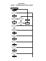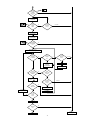
1
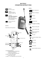
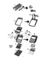
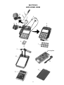
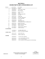
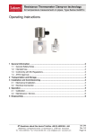
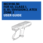
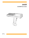
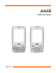
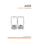
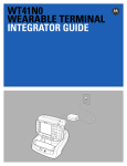
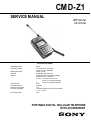
CMD-Z1
SERVICE MANUAL
AEP Model
UK Model
SPECIFICATIONS
Signalling format
Frequency range
GSM power class
SIM chip
Display
Antenna gain
Channel spacing
Number of channels
Frequency stability
RF output power
GSM
Transmit: 890 ~ 915 MHz
Receive: 935 ~ 960 MHz
Class 4 (2 W)
Pluggable mini SIM card
High resolution full graphics display
Resolution: 97 x 32 pixels
5 lines: 1 header line for icons
2 lines x 11 large characters
or
4 lines x 16 small characters
0 dB
200 kHz
124
Transmit frequency drift (synchronized)
< ± 0.1 p.p.m.
2W
PORTABLE DIGITAL CELLULAR TELEPHONE
WITH ACCESSORIES
Power requirements
Battery life
Operating temperature
Storage temperature
Battery pack charging temperature
Dimensions
Weight
Volume
Accessories
5.4 V ~ 8.4 V dc
Standby : up to ±80h
Talk time : minimum 4h up to 10h
–25°C to +55°C
–40°C to +70°C
+0°C to +40°C
133 mm (265 mm with antenna and microphone arm
opened) (H) x 60 mm (W) x 26 mm (D)
220 g
120 cm3
QN-020BC (desk top charger), QN-011AC (AC adaptor),
QN-012AC (AC adaptor - UK), QN-021BC (travel charger Euro), QN-022BC (travel charger - UK), QN-022HFK (hands
free kit), QN-022BP (battery pack), QN-022DC (cigar lighter
charger), QN-022PCM (PCMCIA card)
Design and specifications are subject to change without prior notice.
This appliance conforms with EEC Directive 87/308/EEC regarding interference suppression.
2
SECTION 1
OPERATING INSTRUCTIONS
Display
End Key.
Press to end calls.
Battery charge level.
Call Key.
Press after dialling a
number to make a call
Mail box message(s)
Clear Key
Press short to erase last
digit or letter. Press long to
erase total number or
name. If in menu, press to
go one level back.
R
No service
Press to enter menu
structure.
MENU
Roaming
ABC
Character input
Icons which appear in standby
mode
Antenna
Barring incoming calls
Extend fully for best operation.
Barring outgoing calls
ON/OFF SLIDER SWITCH
INCOMING CALL
WARNING LED
Barring incoming and
outgoing calls
ANTENNA
JOG DIAL
Call divert
REC/PLAY BUTTON
EARPIECE
FLIP-DOWN MICROPHONE
DISPLAY
You have missed incoming
calls
Carry mode
Silent mode
MENU BUTTON
SIMCARD HOLDER
C
SIMCARD HOLDER
RELEASE BUTTON
In car mode
ringer off (volume set to 0)
CAR EXTENSION
CONNECTOR
• Flip down microphone
•
•
– activates incoming call (flip-down)
– stops active call (flip-up)
– activates outgoing call (flip-down)
jog dial : jog and enter (push)
– dial for menu control
rec/play : to record/playback up to 20 seconds
3
SECTION 2
DISASSEMBLY
IMPORTANT NOTES :
1) Disassembly of the RF/Logic Assembly, including the Lower Shield (on which the
IMEI sticker is mounted) and all other shielded elements is totally forbidden. Any
attempt to do so may lead to non-compliance with GSM as well as CE
specifications, and in extreme cases it can cause interference problems.
2) When replacing cosmetic parts, verify if all spacers are mounted on the new
cosmetic; if necessary transplant them from the old to the new cosmetic part.
3) When reassembling, make sure all screws are tightened fully.
• Remove the SIM Card Holder (1).
• Remove the Antenna (2) using the Antenna Jig; also remove the Antenna Ring (3) which is pressed over the
•
•
•
•
•
•
•
•
•
•
•
•
top/bottom cosmetic part. Note the position (top/down side) of this ring for correct reassembly.
Remove the Battery Lid (4) and the Battery (5).
Unscrew four screws (a) on the Battery Compartment.
The Lower Case Assy (6) can now be lifted; however, it is still tightened as the top side is held together with
claws.
Lifting the Lower Case Assy is preferrably performed gently on the antenna side. When reassembling this
part, first insert the REC/PLAY button side.
The RF/Logic Board (7) along with the Microphone Arm Assy (8) can now be taken out. Note, however, that
the RF/Logic Board is still held onto the Display Board through a connector located at the bottom/left side
between the two boards, so at this point still invisible.
To remove the RF/Logic Assy (7), including the Microphone Arm Assy (8), first of all put the Microphone Assy
to an angle of 90° versus the set. Next, push the Microphone Assy gently upward while at the same time
pushing the Microphone Holding Part of the Upper Housing Assy downward (b). This should release the
RF/Logic Assy from the rest of the set.
The Microphone Arm Assy can be released by unscrewing one screw (d).
When reassembling this board, gently push in the bottom/left corner to insert the RF/Logic side connector
into the display connector side.
When disassembling the RF/Logic Board, three Plastic Sleeves (10) will come loose; note their position for
correct reassembly.
The Display Board (11) can now be taken out of the Upper Housing Assy (12).
The Jog Mounted PCB (13) can be taken out of the Lower Case Assy after unscrewing four screws (c). Note
that one of these screws has a large head.
Underneath the Jog there is a Jog Shielding (14).
4
5
SECTION 3
LEVEL 1 TROUBLESHOOTING CHART
Insert simcard, insert new battery
Close microphone, antenna down
Switch on
Does it
switch on
correctly?
N
Y
Input pincode
N
Does it
find network and
goes to normal
waiting status?
N
Is it showing
searching screen?
Power off
Y
Y
Push keys
0-9* and #
Display
showing correct
key input?
Does set
show sufficient
signal strength?
N
Y
Y
When
pushing keys,
does backlight and
keylight go on for
10 sec?
N
Y
Push menu key
Is correct
menu screen
displayed,
was sound
o.k.?
N
Y
Click jog
Is menu
item selected,
was sound
o.k.?
N
Y
Jog dial up/down
Does
display scroll
up/down
N
Y
Push "C" twice
Did set
go back to
initial waiting
screen
N
Y
Open microphone arm
1
6
N
Move to place
with better
network coverage
1
Does
cursor appear
on display,
was sound
o.k.?
N
display
Y
<2
Push rec key
continuously
Is correct
display
shown
display
N
How many
times did
you try?
3 or more
Y
Perform
voice recording
Push rec/pb
key (short push)
Is playback
and pb display
o.k.?
display
N
Y
Dial a known number
(your own wired line, speaking clock etc....)
Do you get
connection
to network?
N
Antenna
strength
o.k.?
How many
times did
you try?
Y
N
Y
Move to place
with better
signal strength
3 or more
<2
Perform off/on
Input pincode
N
Is normal
communication
enabled?
N
Does
display show
"active"?
Y
Y
End connection,
push
Correct
end of call?
How many
times did
you try?
N
3 or more
<2
Perform off/on
Try again from
known source
Y
N
Input pincode
Can you
receive
a call?
Y
Switch off
Switch off
o.k.?
N
Y
Set not o.k.,
send to repair
Set o.k.
7
SECTION 4
PROGRAMMING INSTRUCTIONS
1. Setup
The programming jig is based upon a PC-linked application.
Minimum requirement for PC is IBM compatible, 386 type.
The software is a basic MS−DOS application. Please do NOT run it as a DOS mode application starting from a
Windows program. It is necessary to exit Windows when starting the PC-link application, or preferrably to start
the PC without entering Windows.
The jig consists of: Level Convertor, Connection Cables (PC to Level Convertor and Level Convertor to CMD−Z1)
and application software on floppy disc.
No specific software installation is needed; only copy all the files from the floppy disc to the PC, ideally into a
dedicated directory.
Starting of the software updating program will take place when going to the directory where you have loaded
the application program and typing CMD−Z1 + enter.
2. Important notes
• Before connecting the CMD−Z1 to the level convertor, take out the battery of the CMD−Z1; the CMD−Z1
must be powered from the level convertor.
• Whenever the program is in progress, or when the level convertor is powered on, never disconnect or connect
•
•
any cables.
Never interrupt the power supply to the level convertor whenever a software update is in progress.
The level convertor has some switches; please make sure they are in the correct position. These switches
are included also to allow future changes, or other applications.
3. Menu screens
The program will show the following masks according to the respective menu points.
At the first menu point, the following mask is displayed:
Program-CMD-Z1 Service Station Utility
Version: X.XX for PC (DOS)
Mode: Update AP/OS code and change the Language set
(C) Copyright XXXX, XXXX Sony Corporation. All rights reserved
Current Status
Serial Port: COM 1, 19200, N81
1. Update.
2. Serial Port Setting
Please make choice (1/2) = 1
The user can either choose the serial port or go for the updating option immediately.
The default setting for the serial port is COM1.
NOTE If a port were chosen which is not connected to the Level Shifter, the error message “No Response”
would be displayed after starting the update process.
8
If option 1 has been chosen, the following display will appear:
Flash ROM Type – Sharp 30 23
Set the switch of the voltage convertor as follows.
Vpp = on; FROMRP = off
After you set the switch, type any key to proceed.
The user is requested to set the switches on the Level Shifter to the settings displayed.
To enable the ROM Loader Software to determine the ROM manufacturer and hence the switch settings, the
ROM−ID is read first from the Z1. The settings shown in the sample above are only valid for a Sharp ROM and
are therefore only an example. Future ROM types may come from a different manufacturer. After setting the
switches on the Level Shifter, press any key to proceed.
NOTE If the connection has been set up successfully, the green lamp on the Z1 display starts flashing.
As soon as the connection is established successfully, the current AP and OS software versions are displayed
as well as the latest versions to ensure that the service operator is fully aware oft he differences of both software
versions.
Proceeding the program leads to the following simple options from which the operator is requested to choose:
– Update AP? (y/n/c) or
– Update OS? (y/n/c) or
– Change Language Set? (y/n/c)*
The operator does not have to change the Language Set or any other item he does not want to change at this
time. Thus it is possible to change the operating system (OS) only while the application code (AP) and the
Language Set remain unchanged.
NOTE Typing in “c” (cancel) will interrupt the updating process at any time and will abandon the program.
* The request to update AP(y) makes a language set change necessary.
Therefore the message : “Default new language setting because of AP code change”, appears instead
of “change language set” (y/n/c)
9
General information
• No GSM test mode is implemented in the Z1 for use with the ROM Loader Software. For the software or the
•
Language Set update simply connect the Z1 with the Level Shifter and run the ROM Loader Software
(CMD−Z1.EXE). The Z1 does not have to be switched on!
The switch settings of the Level Shifter are as follows:
Switch
Intel ROM
Sharp ROM
Main power
always on
always on
Vpp
off
on
IGN/Vpp
always on
always on
FROMRP
disabled (factory set to off position)
disabled (factory set to off position)
GSM power
always on
always on
Troubleshooting
• Cause 1
•
– The error message “ERROR : SIO Receive timeout” appears after starting the program and trying to
set up the connection between PC and Z1.
Remedy 1
– Check the connection between MT (mobile terminal), Level Shifter, and PC. Also make sure that the
Level Shifter’s power is switched on (both switches). Both the Main Power LED and the GSM Power
LED must light up.
– Check whether COM1 or COM2 is active.
10
SECTION 5
EXPLODED VIEW
1
18
2
3
5
4
17 16
6
15
8
7
12
11
* not supplied
10
9
14
13
11
SECTION 6
SPARE PARTS AND ACCESSORIES LIST
Ref. No.
Part number
Description
1
1-501-782-11
Antenna
2
3-929-538-01
Tube, Antenna Guide
3
3-929-542-01
Ring, Antenna
4
3-929-551-01
Screw, Antenna
5
3-929-540-01
Sleeve
6
X-3372-058-1
Housing (Upper) Assy
7
3-929-539-01
Pad, Key
8
3-932-747-01
Holder SIM
9
X-3372-069-1
Arm Assy, Microphone
10
A-3642-683-A
Case (Lower) Assy
11
3-935-533-03
Jog Shield
12
A-3622-007-A
Jog Mounted PCB
13
1-528-618-11
Rechargeable Lithium Ion Battery Pack
14
X-3372-124-1
Battery Cover Assy
15
3-929-534-01
Bottom Connector Cover
16
3-013-808-01
Spacer, Antenna
17
3-013-809-01
Adhesive Sheet, Antenna
18
3-012-064-01
Insulator Antenna
1-473-004-12
AC Adaptor QN-011AC
1-528-665-11
Desk Top Charger QN-020BC
3-935-127-01
Antenna Driver Jig
9-948-320-40
Software Update Jig
3-929-548-01
1.7 x 6 PTT (for Jog Assy)
3-007-531-01
1.7 x 6 Large Head (for Jog Assy)
3-939-146-01
1.7 x 6 + P (for Arm Assy)
3-929-541-01
1.7 x 9 Torques (for Lower Shield & Lower Case Assy)
ACCESSORIES
JIGS & TOOLS
SCREWS
9-948-412-10
Customer Relations & Service Europe
European Technical Support
12
English
Printed in Belgium
© 1997.02
Published by ETS