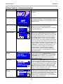
1
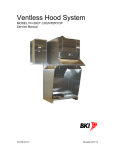
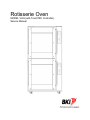
Rotisserie Oven
MODEL VGG (with TouchTEC Controller)
Service Manual
Warranty Information
LIMITED ONE YEAR WARRANTY
BKI (The "Company") warrants to the original purchaser that at time of shipment from the
Company factory, this equipment will be free from defect in materials and workmanship. Written
notice of a claim under this warranty must be received by the Company within ONE YEAR from
the date of installation, but no longer than ONE YEAR AND THREE MONTHS from date of
shipment from the factory. Defective conditions caused by abnormal use or misuse, lack of or
improper maintenance, damage by third parties, alterations by unauthorized personnel, acts of
God, failure to follow installation and/or operating instructions, or any other events beyond the
reasonable control of the Company will NOT be covered under this warranty. The obligation of
the Company under this warranty shall be limited to repairing or replacing (at the option of the
Company) any part, with the exception of lamps, fuses, and glass (which are not covered under
warranty), which is found defective in the reasonable opinion of the Company. Any part found
defective by the Company will be repaired or replaced without charge F.O.B. factory,
Simpsonville, South Carolina or F.O.B. authorized BKI Distributor. The Company and/or its
authorized representatives will assume the normal replacement labor expense for the defective
part for the period of the warranty as stated above, excluding travel and/or other expenses
incidental to the replacement of the defective part, where replacement work is performed during
standard business hours and not subject to overtime, holiday rates, and/or any additional fees. IN
NO EVENT SHALL THE COMPANY BE LIABLE FOR LOSS OF USE, LOSS OF REVENUE OR
LOSS OF PRODUCT OR PROFIT OR FOR INDIRECT OR CONSEQUENTIAL DAMAGES
INCLUDING BUT NOT LIMITED TO, FOOD SPOILAGE OR PRODUCT LOSS. WARRANTY
DOES NOT COVER GLASS BREAKAGE. THE ABOVE WARRANTY IS EXCLUSIVE AND ALL
OTHER WARRANTIES, EXPRESS OR IMPLIED, ARE EXCLUDED INCLUDING THE IMPLIED
WARRANTIES OF MERCHANTABILITY AND FITNESS FOR A PARTICULAR PURPOSE.
REPLACEMENT PARTS
Any appliance replacement part, with the exception of lamps, fuses, and glass, which proves to
be defective in material or workmanship within ninety (90) days of installation will be replaced
without charge F.O.B. Factory, Simpsonville, SC or F.O.B. authorized BKI Distributor. The user
shall have the responsibility and expense of removing and returning the defective part to the
Company as well as the cost of reinstalling the replacement or repaired part.
Rotisserie Oven
Table of Contents
Table of Contents
Table of Contents .................................................................................................................................................... 1
Introduction.............................................................................................................................................................. 2
Safety Precautions ................................................................................................................................................ 2
Safety Signs and Messages ............................................................................................................................. 2
Specific Precautions ......................................................................................................................................... 3
Safe Work Practices ......................................................................................................................................... 3
Safety Labels .................................................................................................................................................... 6
Health And Sanitation Practices............................................................................................................................ 7
Food Handling................................................................................................................................................... 7
Storage Of Raw Meats...................................................................................................................................... 7
Coding Cooked Foods ...................................................................................................................................... 7
Storage Of Prepared Foods.............................................................................................................................. 7
Operation.................................................................................................................................................................. 8
Controls and Indicators ......................................................................................................................................... 8
Hardware Controls ............................................................................................................................................ 9
Software Controls – Operation Screens ........................................................................................................... 9
Software Controls – Programming Screens ................................................................................................... 12
Programming the Controller Using the Touchscreen Interface........................................................................... 13
Edit a Recipe................................................................................................................................................... 13
Edit the Basic Setup........................................................................................................................................ 14
Programming the Controller Using the RS-232 Interface ................................................................................... 14
Operation with the Controller .............................................................................................................................. 15
Viewing Recipes ............................................................................................................................................. 15
Cooking ........................................................................................................................................................... 15
Accessory Use .................................................................................................................................................... 16
Standard Meat forks........................................................................................................................................ 16
Baskets ........................................................................................................................................................... 16
Installation.............................................................................................................................................................. 17
Unpacking and Handling ..................................................................................................................................... 17
Location and Clearance ...................................................................................................................................... 17
Extraction ............................................................................................................................................................ 17
Wiring .................................................................................................................................................................. 17
General Guidelines ......................................................................................................................................... 17
Guidelines for European Appliances .............................................................................................................. 20
Operating............................................................................................................................................................. 20
Safety Cut-Out ................................................................................................................................................ 20
Maintenance ........................................................................................................................................................... 21
Scheduled Maintenance...................................................................................................................................... 21
Oven Cleaning (Daily)..................................................................................................................................... 21
Troubleshooting................................................................................................................................................... 24
Parts List ................................................................................................................................................................ 26
Accessories ......................................................................................................................................................... 45
Wiring Diagrams .................................................................................................................................................... 46
Notes....................................................................................................................................................................... 53
1
Rotisserie Oven
Introduction
Introduction
Your BKI VGG is a computer controlled rotisserie oven. It utilizes a revolving mechanism and heating elements
that ensure even product cooking. A touchscreen control and switches are provided to allow for quick setup and
operation. Removable components allow for easy maintenance and cleaning.
The BKI name and trademark on this unit assures you of the finest in design and engineering -- that it has been
built with care and dedication -- using the best materials available. Attention to the operating instructions
regarding proper installation, operation, and maintenance will result in long lasting dependability to ensure the
highest profitable return on your investment.
PLEASE READ THIS ENTIRE MANUAL BEFORE OPERATING THE UNIT. If you have
any questions, please contact your BKI Distributor. If they are unable to answer your
questions, phone the applicable BKI Technical Services Department:
BKI North America: (864) 963-3471
BKI Europe: (44) 0870 9904242
Safety Precautions
Always follow recommended safety precautions listed in this manual. Below is the safety alert symbol. When you
see this symbol on your equipment, be alert to the potential for personal injury or property damage.
Safety Signs and Messages
The following Safety signs and messages are placed in this manual to provide instructions and identify specific
areas where potential hazards exist and special precautions should be taken. Know and understand the meaning
of these instructions, signs, and messages. Damage to the equipment, death or serious injury to you or other
persons may result if these messages are not followed.
This message indicates an imminently hazardous situation which, if not avoided, will
result in death or serious injury.
This message indicates a potentially hazardous situation, which, if not avoided, could
result in death or serious injury.
This message indicates a potentially hazardous situation, which, if not avoided, may
result in minor or moderate injury. It may also be used to alert against unsafe practices.
This message is used when special information, instructions or identification are required
relating to procedures, equipment, tools, capacities and other special data.
2
Rotisserie Oven
Introduction
Specific Precautions
Equipotential Ground Plane
When a high current flows through a conductor, differences in potential appear between
the conductor and nearby metallic surfaces near the appliance. As a result, sparks may
be produced between the appliance and surrounding metal surfaces. These sparks
could cause serious injury, damage, or fire.
BKI provides an Equipotential ground terminal for the connection of a bonding conductor
after the installation of the appliance per lEC60417-1. This terminal is located on the
drive side of the oven base and is marked with this symbol.
Full Disconnection for IEC / CE Regulations
In accordance with Local and/or National wiring codes, the installer must provide a
means of full disconnection for overvoltage Category III conditions. An IEC approved
cord and plug combination will meet this requirement.
Units not provided with a cord and plug do not meet this requirement. In accordance with
Local and/or National wiring codes, the installer must provide the means of full
disconnection.
Safe Work Practices
Wear Safe Clothing Appropriate To Your Job
Always wear your insulated mitts when handling hot oven parts or touch any hot
metal surface. If you lose or damage your mitts, you can buy new ones at your local
restaurant equipment supply store or from your local BKI Distributor.
Always wear non-skid shoes when working around the oven or any other
equipment.
Never wear loose clothing such as neckties or scarves while operating this
equipment. Keep loose hair tied back or in a hair net while operating this
equipment.
Always wear appropriate personal protection equipment during the cleaning
process to guard against possible injury.
3
Rotisserie Oven
Introduction
WARNING – DANGEROUS VOLTAGE
This equipment uses high voltage. Serious injury can occur if you or any untrained
or unauthorized person installs, services, or repairs this equipment. Always Use an
Authorized Service agent to Service Your Equipment.
Keep this manual with the Equipment
This manual is an important part of your equipment. Always keep it near for easy
access. If you need to replace this manual, phone the applicable BKI Technical
Services Department:
BKI North America: (864) 963-3471
BKI Europe: (44) 0870 9904242
Protect Children
Keep children away from this equipment. Children may not understand that this
equipment is dangerous for them and others.
NEVER allow children to play near or operate your equipment.
Keep Safety Labels Clean and in Good Condition
Do not remove or cover any safety labels on your equipment. Keep all safety labels
clean and in good condition. Replace any damaged or missing safety labels. Refer
to the Safety Labels section for illustration and location of safety labels on this unit.
If you need a new safety label, obtain the number of the specific label illustrated on
page 6, then phone the applicable BKI Technical Services Department:
BKI North America: (864) 963-3471
BKI Europe: (44) 0870 9904242
4
Rotisserie Oven
Introduction
Be Prepared for Emergencies
Be prepared for fires, injuries, or other emergencies.
Keep a first aid kit and a fire extinguisher near the equipment. You must use a 40pound Type BC fire extinguisher and keep it within 25 feet of your equipment.
Keep emergency numbers for doctors, ambulance services, hospitals, and the fire
department near your telephone.
Know your responsibilities as an Employer
• Make certain your employees know how to operate the equipment.
• Make certain your employees are aware of the safety precautions on the
equipment and in this manual.
• Make certain that you have thoroughly trained your employees about operating
the equipment safely.
• Make certain the equipment is in proper working condition. If you make
unauthorized modifications to the equipment, you will reduce the function and
safety of the equipment.
5
Rotisserie Oven
Introduction
Safety Labels
6
Rotisserie Oven
Introduction
Health And Sanitation Practices
BKI Rotisserie Ovens are manufactured to comply with health regulations and are tested and certified to NSF and
FSA standards. You must operate the equipment properly, using only quality products and use meat
thermometers to insure meats are thoroughly cooked.
Food Handling
•
Wash hands thoroughly in warm, soapy water after handling raw poultry or meats.
•
Clean and sanitize all utensils and surfaces that have been in contact with raw products. Clean and
sanitize the meat forks or baskets between cooking.
•
Never place cooked meats on the same surfaces used to prepare raw meats, unless the area has been
thoroughly cleaned and sanitized.
Storage Of Raw Meats
•
Designate an area or shelf strictly for the storage of all raw meats to be used in the rotisserie.
•
Raw product must always be stored at temperatures below 38° F. (3° C.).
•
Never store or mix raw foods above cooked foods, as this is a health hazard. The drippings from raw
foods contaminate cooked or processed foods.
•
All chicken and chicken parts to be stored overnight must be thoroughly iced down and refrigerated.
Coding Cooked Foods
All products cooked during the day should be sold the same day.
NOTE: It is not the intent of the rotisserie program to have unsold merchandise at the end of the cooking day.
Follow your company’s procedures for the handling of any leftover product.
Storage Of Prepared Foods
•
Cold foods should be kept at or below 38° F. (3° C.).
•
Hot foods must be maintained to meet local health codes, usually a minimum 145° F. (63° C.).
7
Rotisserie Oven
Operation
Operation
Controls and Indicators
8
Rotisserie Oven
Operation
Hardware Controls
Item #
1
2
3
4
Description
Rotor Switch
Main Power Isolator
Light
Main Power Switch
Analog Touchscreen
Controller
Function
Depressing the switch allows the operator to “jog” the rotor position when the
door is open. Releasing the switch stops the rotor.
This light illuminates to indicate that power is being applied to the oven from
the Main Power Isolator (Circuit Breaker).
Turns power to the entire unit on or off. When placed in the on position, the
Touchscreen controller is powered, lights illuminate and the rotor motor
engages (if both doors are closed). When placed in the off position, power is
removed from the entire unit.
Used for operation and programming of the oven. A built-in beeper is used to
indicate touchscreen presses and other oven functions. It has 15
programmable cooking recipes.
Software Controls – Operation Screens
Screen Name
Screen
Description
Startup
Appears when the Main Power Switch is placed in the
on position.
Controller Off
Appears after the Startup screen displays. This screen
Indicates that the controller is turned off. Touching
anywhere on the screen will turn the controller on and
display the Recipe Selection screen.
Recipe Selection
Displays a the list of available recipes. The up and down
arrow buttons move the highlight box from one recipe to
the next. Once the desired recipe is highlighted the user
touches the GO button to start the cook cycle. Touching
the X button for 3 seconds turns the controller off.
Touching any recipe will show the settings for that
recipe.
Displays Preheat Temperature, Cook Temperature,
Cook Time, Hold Temperature and Cook To settings for
a selected recipe. Touching the up and down arrow
buttons scroll the screen to view more settings.
Touching the X button momentarily returns you to the
previous screen.
Displays once the user highlights a recipe and touches
the GO button if the recipe has a preheat temperature
programmed. The user selects where to start the
cooking cycle by touching Preheat or Cook. Touching
Preheat displays the Preheat screen. Touching Cook
displays the Ready To Cook screen. If the Preheat
temperature is set to OFF the controller goes directly to
the Ready To Cook screen. The T button can be used to
display the current oven temperature. Touching the T
button displays the temperature, then automatically
returns to the previous screen in 2 seconds. Touching
the X button momentarily returns you to the previous
screen.
Recipe Settings
RECIPE 02
Preheat Temp: 360F
Cook Temp: 360F
Cook Time: 1:10
Preheat/Cook
Selection
RECIPE 02
Preheat
Cook
T
9
Rotisserie Oven
Operation
Screen Name
Preheat
Screen
Ready to Cook
Cooking
RECIPE 02
H
T
Time
0:50
EXTRA
Description
Displays once the user touches the Preheat option from
the Preheat/Cook Selection screen. The Preheat cycle
heats the cooking cavity up to the pre-defined preheat
temperature. Once this temperature is reached the unit
automatically switches to the Ready To Cook mode. A
small highlighted letter H will appear to the right of the
temperature display to indicate that the controller has
energized the heating elements. The absence of the
letter H indicates that the controller has de-energized
the heating elements as the oven temperature has
reached the set temperature limit. The T button works
as described for the Preheat/Cook Selection screen.
Touching the X button for 3 seconds returns you to the
Recipe Selection screen.
Displays once the user touches the Cook option from
the Preheat/Cook selection screen or once the preheat
cycle is finished or directly from the Recipe Selection
screen if no preheat temperature was programmed.
When the temperature is within 5° of the cook
temperature the controller will emit three 2 second
beeps indicating that the product can be loaded. The
user places the product to be cooked into the cooking
cavity and touches the COOK button to start the cooking
process. If the door is opened and/or the temperature
drops below 25° below the preheat temperature, the
screen will flash and beep every 30 seconds until the
COOK button is touched. The highlighted letter H works
as described for the Preheat screen. The T button works
as described for the Preheat/Cook Selection screen.
Touching the X button for 3 seconds returns you to the
Recipe Selection screen.
Displays once the COOK button is touched from the
Ready To Cook screen. This screen shows the cooking
temperature, the time remaining in the cook cycle, and
the elapsed time shown with the progress bar at the
bottom of the screen. Hold the X button for 2 seconds to
stop the cook in progress. The EXTRA button can be
used to add more cook time to the cycle. The cook cycle
ends when the cook time elapses. This is indicated by
three 2 second beeps. If a hold temperature was
programmed then the Hold screen is displayed. If no
hold temperature was programmed then the screen will
flash and beep until touched. The highlighted letter H
works as described for the Preheat screen. The T button
works as described for the Preheat/Cook Selection
screen. Touching the X button for 3 seconds returns you
to the Preheat/Cook Selection screen.
10
Rotisserie Oven
Screen Name
Hold
Extra Cook
Operation
Screen
Description
Displays once the cook cycle is complete if a hold
temperature was programmed. This screen displays the
hold temperature (or nothing if set to OFF), and the
elapsed time in the hold mode. The EXTRA button is
available here so the product can be cooked for more
time if required. The highlighted letter H works as
described for the Preheat screen. The T button works as
described for the Preheat/Cook Selection screen.
Touching the X button for 3 seconds returns you to the
Recipe Selection screen.
Appears when the EXTRA button is touched from the
Cooking or Hold screens. Use the up and down arrow
buttons to set the amount of additional cook or hold time
in 5 minute increments. Touch the GO button to add the
additional time you set. Touch the X button to return to
the previous screen without adding any extra cook or
hold time.
11
Rotisserie Oven
Operation
Software Controls – Programming Screens
Screen Name
Startup
Screen
Controller Off
TOUCH TO START
Recipe Selection
Program Security
RECIPE 01
RECIPE 02
RECIPE 03
RECIPE 04
ENTER CODE
0000
Program Mode
Selection
Basic Setup
Recipe Edit
Selection
Description
Appears when the Main Power Switch is placed in the
on position.
Appears after the Startup screen displays. Indicates that
the controller is turned off. Touching anywhere on the
screen will turn the controller on and display the Recipe
Selection screen.
Appears once the Controller Off screen is touched.
Touch any recipe for 3 seconds to enter the
programming mode. Touch the X button for 3 seconds
to turn the controller off.
Appears upon entering the programming mode and is
used to enter a 4 digit passcode. When the controller is
first powered, 0000 is used to access the programming
mode. Upon subsequent access, if you don’t want to
use a special passcode but want to leave it 0000 just
press the GO button. If you do want to use a special
passcode, configure one using the Basic Setup screen.
Use the left and right arrow buttons to move the cursor
under the digit to be changed. The up and down arrow
buttons increase or decrease the digit as desired. Touch
the GO button to submit the security passcode. If the
passcode is valid the Programming mode Selection
screen will appear. If the passcode is invalid the
Program Security screen will reappear showing the
passcode you entered. Touch the X button to return to
the previous screen.
Appears once a valid passcode is entered from the
Security screen. Touch the BASIC SETUP option to
change basic controller parameters. Touch the COOK
PROGRAMS option to change cook parameters for a
specific recipe. Touch the X button to return to the
Recipe Selection screen.
Appears when the BASIC SETUP option is touched
from the Programming Mode Selection screen. Use this
screen to configure the controller to display temperature
in Fahrenheit of Centigrade, to use short or long beeps
at the end of a cook cycle and to modify the four digit
passcode. The E in the bottom right corner toggles
between English and Spanish on the display. Touch the
X button to return to the previous screen.
Appears when the COOK PROGRAMS option is
touched from the Programming Mode Selection screen.
This screen is used to select the recipe you want to edit.
Use the up and down arrow buttons to highlight the
recipe then touch the EDIT button. Touch the X button
to return to the previous screen.
12
Rotisserie Oven
Screen Name
Recipe Parameter
Selection
Recipe Parameter
Edit
Operation
Screen
Description
Appears when a recipe is selected and the EDIT button
is touched from the Recipe Edit Selection screen. This
screen is used to select a specific recipe parameter to
edit. Use the up and down arrow buttons to scroll
through the list of parameters and touch the parameter
you want to change. Touch the X button to return to the
previous screen.
Appears when a recipe parameter is touched from the
Recipe Parameter Selection screen. This screen is used
to edit a specific recipe parameter. The editable
parameters are: Recipe name, Preheat Temp, Cook
Temp, Cook Time and Hold Temp. The left and right
arrow buttons are used to move the cursor under the
character to be changed. The up and down arrow
buttons changes the character as desired. The Preheat
Temp and Hold Temp parameters can be turned off by
scrolling the temperature below 150°. Touch the SAVE
button to save the changed parameter. Touch the X
button to abort all changes and return to the previous
screen.
Programming the Controller Using the Touchscreen Interface
Use the procedures below to edit a separate recipe or to change the basic controller configuration.
Edit a Recipe
1. Turn on the Main Power Switch. The Startup screen will briefly appear then the Controller Off screen will
display.
2. Touch anywhere on the touchscreen. The Recipe Selection screen will appear displaying a list of recipes.
3. Touch any recipe for 3 seconds. The Security screen will appear.
4. Use the up/down and left/right arrow buttons to enter the passcode and touch the GO button. The
Program Mode Selection screen will appear if a valid passcode is entered.
5. Touch the COOK PROGRAMS option. A Recipe Edit Selection screen will appear.
6. Highlight the recipe you want to edit using the up/down arrow buttons then touch the EDIT button. The
Parameter Selection screen will appear.
7. Use the up/down arrow buttons to view the recipe parameters and touch the parameter you want to edit.
The Parameter Edit screen will appear.
8. Change the parameter value using the left/right and up/down arrow buttons then touch the SAVE button
to save your changes. You will return to the Parameter Selection screen.
9. Repeat the process to change any other parameters.
10. Touch the X button as necessary to return to the Recipe Selection screen.
13
Rotisserie Oven
Operation
Edit the Basic Setup
1. Turn on the Main Power Switch. The Startup screen will briefly appear then the Controller Off screen will
display.
2. Touch anywhere on the touchscreen. The Recipe Selection screen will appear displaying a list of recipes.
3. Touch any recipe for 3 seconds. The Security screen will appear.
4. Use the up/down and left/right arrow buttons to enter the passcode and touch the GO button. The
Program Mode Selection screen will appear if a valid passcode is entered.
5. Touch the BASIC SETUP option. A Basic Setup Selection screen will appear.
6. Touch the parameter that needs to be changed. A Basic Setup Parameter Edit screen appears.
7. Change the parameter value using the left/right and up/down arrow buttons then touch the SAVE button
to save your changes. You will return to the Basic Setup Selection screen.
8. Repeat the process to change any other parameters.
9. Touch the X button as necessary to return to the Recipe Selection screen.
Programming the Controller Using the RS-232 Interface
The TouchTEC controller incorporates an RS-232 interface allowing factory and field personnel to read out,
modify and write in the entire recipe and controller configuration using a special Controller Configuration program
on a PC. The program allows a user to read the configuration data from the controller, edit any feature of the
configuration, write data back to the controller, save the data to a file on the PC and to retrieve the data from a
previously created file. The file saved in the PC contains a description field to aid in identifying the contents of the
configuration file. Follow the steps below to program the controller using the RS-232 interface.
1. Connect the communications interface module between the serial port on the PC and the controller.
2. Start the Controller Configuration program.
3. Select the COM port that the controller will use to communicate with the PC from the pull down list in the
Controller Com area.
4. Click the OPEN button and select a previously created configuration file or click the READ button to
download the configuration data from the controller.
5. Edit any of the following: Description of the configuration file, Recipe Parameters, Max number of recipes
visible, four digit passcode, Unit of Measurement for Temperature display and the Beep Type used at the
end of the cook cycle.
6. Touch the SAVE button and save the file using a different name.
7. Touch the WRITE button to upload the new configuration data back to the controller.
8. Disconnect the the communications interface module between the serial port on the PC and the
controller.
14
Rotisserie Oven
Operation
Operation with the Controller
Use the procedures below to view a separate recipe or to activate a cook cycle using a one of the
preprogrammed recipes.
Viewing Recipes
1. Turn on the Main Power Switch. The Startup screen will briefly appear then the Controller Off screen will
display.
2. Touch anywhere on the touchscreen. The Recipe Selection screen will appear displaying a list of recipes.
3. Use the up/down arrow buttons to highlight the recipe you wish to view then touch it. A Recipe Settings
screen will appear.
4. Use the up/down arrow buttons to view any settings for the recipe selected.
5. Touch the X button momentarily to return to the previous screen.
Cooking
1. Turn on the Main Power Switch. The Startup screen will briefly appear then the Controller Off screen will
display.
2. Touch anywhere on the touchscreen. The Recipe Selection screen will appear displaying a list of recipes.
3. Use the up/down arrow buttons to highlight the recipe you wish to use then touch the GO button. If a
preheat temperature was programmed then the Preheat/Cook Selection screen will appear. If no preheat
temperature was programmed then the controller enters the Ready To Cook mode displaying the Ready
To Cook screen.
•
If the Preheat/Cook Selection screen appears, do either of the following:
• Touch the Preheat option to enter the Preheat mode. The controller will display the Preheat
screen. Once the preheat temperature is reached the controller enters the Ready To Cook mode.
• Touch the Cook option to enter the Ready to Cook mode.
Once the temperature is within 5° of the cook temperature in the Ready To Cook mode the controller will
emit three 2 second beeps indicating that the oven can be loaded with product.
4. Load the product into the oven. Use the Rotor Switch on the front panel to operate the rotors during
loading.
5. Close the door.
6. Touch the COOK button. The controller now enters the cook mode and displays the cooking temperature,
time remaining in the cook cycle and the elapsed time. If necessary, use the EXTRA button to add more
cook time to the cycle. At the end of a cook cycle the controller will emit three 2 second beeps and enter
the Hold mode and display the Hold screen if a Hold temperature was programmed. If a Hold temperature
was not programmed the screen will flash and beep until touched.
7. Open the oven door and check the product for proper internal temperature. If necessary, use the EXTRA
button to add more cook time.
8. Unload the product if it is done.
15
Rotisserie Oven
Operation
Accessory Use
Standard Meat forks
The standard meat forks are ideal for chicken and poultry. Use the following procedure to prepare the bird for
loading in the oven.
1. Fold wings to back, place on back with cavity away from you.
2. Run pointed ends of meat fork through sides of chicken under wings and through thighs (breast up and
legs down). Ensure that legs of adjacent birds DO NOT PRESS TIGHTLY TOGETHER, this will cause
the area of contact to be under-cooked!
3. Load the meat-forks by holding the meat-fork with the handle to the right–hand side, facing up.
4. Open the oven door.
5. Press Rotor Switch to rotate rotor to open position if required.
6. Place the pointed ends of the meat-fork into the left-hand disc holes.
7. From the control side, push the meat-fork into the disc to allow the right-hand (handle end) pins locate
into the right-hand disc.
8. Be sure to adjust the meat-fork position so that the handle end locates firmly in the spit groove.
Baskets
Baskets can be used for large chickens or other meats. After loading with product, simply locate pins in the holes
on the discs.
16
Rotisserie Oven
Installation
Installation
Serious injury, equipment damage or death could result if attempting to install this oven
yourself. Ensure that an authorized BKI service agent install the oven.
Unpacking and Handling
It is the owners’ responsibility to file all freight claims with the delivering truck line. Inspect all cartons and crates
for damage as soon as they arrive. If damage to cartons or crates is found, or if a shortage is found, note this on
the bill of lading (all copies) prior to signing.
If damage is found when the equipment is opened, immediately call the delivering truck line and follow up the call
with a written report indicating concealed damage to your shipment. Ask for an immediate inspection of your
concealed damage item. Packaging material MUST be retained to show the inspector from the truck line.
Remove all packing from the interior and exterior of the oven.
Location and Clearance
The oven must be mounted on a level surface capable of supporting the fully loaded oven. Refer to Chart 1 for
oven weight.
Adequate clearance must be provided around the oven for safety, proper operation and ventilation. Refer to
Chart 1 for required minimum clearances. Note that these are minimum clearances. If the oven is to be
permanently mounted near other immovable objects additional clearance must be provided for connection and
service of the oven on both sides.
All ventilation slots must be kept free from obstruction.
Extraction
Extraction is not a specific requirement for this type of appliance. Certain conditions, e.g./ installation in a confined
space, temperature controlled environment, continuous use or high volume production cooking may require the
need for extra ventilation or extraction. Consult your local ventilation/extraction air conditioning company or
contact the technical services department at BKI.
Wiring
Electrocution, equipment failure or property damage could result if an unlicensed
electrician performs the electrical installation. Ensure that a licensed electrician perform
the electrical installation in accordance with applicable local and national codes.
General Guidelines
•
In the absence of local codes refer to the latest edition of one of the following:
• National Electrical Code, ANSI/NFPA 70-20XX (USA) which can be obtained from:
The National Fire Protection Association
Batterymarch Park
Quincy, MA 02269
•
•
• I.E.E. Wiring Regulations (Europe)
Verify that the power supply conforms to the electrical rating listed on the oven data plate.
Ensure that the appliance is grounded (earthed).
17
Rotisserie Oven
Installation
Chart 1. Location and Clearance
Electrical Specifications (North America)
1Ph + Gnd, 60Hz
Volts
Amps
KW
Breaker
208
29.3
6.1
40
220
23.5
5.2
30
240
27.8
6.7
40
Electrical Specifications (North America)
3Ph + Gnd, 60Hz
Volts
Amps
KW
Breaker
208
17.2
6.1
25
220
13.8
5.2
20
240
16.3
6.7
25
Electrical Specifications (Europe)
230/400 Volts, 3Ph + Gnd + E, 50Hz
Amps
Watts
Breaker
L1
9.3
2182
10
L2
9.3
2130
L3
9.2
2120
Model
VGG-5
Height
1009.5 mm
39.7 in.
Shipping
Weight
195 KG
430 lb.
Minimum Clearance
Combustible Surface
Non-Combustible Surface
152.5 mm
152.5 mm
6 in.
6 in.
18
Rotisserie Oven
Installation
Electrical Specifications (North America)
3Ph + Gnd, 60Hz
Volts
Amps
KW
Breaker
208
32.2*
11.1*
45*
220
28.2*
10.3*
40*
240
30.1*
12.0*
40*
* Ratings per oven cavity. VGG-16 requires a
separate power supply for each oven cavity.
Electrical Specifications (Europe)
230/400 Volts, 3Ph + Gnd + E, 50Hz
Model
Amps
KW
Breaker
VGG-8
16.3
10.9
25
VGG-16
32.2
21.8
32
Model
VGG-8
VGG-16
Height
1003.3 mm
39.5 in.
2008.2 mm
79 1/16 in.
Shipping
Weight
259 KG
570 lb.
453 KG
1000 lb.
Minimum Clearance
Combustible Surface
Non-Combustible Surface
A
B
C
A
B
C
152.5 mm 152.5 mm 152.5 mm
51.0 mm
51.0 mm
51.0 mm
6 in.
6 in.
6 in.
2 in.
2 in.
2 in.
152.5 mm 152.5 mm 152.5 mm
51.0 mm
51.0 mm
51.0 mm
6 in.
6 in.
6 in.
2 in.
2 in.
2 in.
19
Rotisserie Oven
Installation
Guidelines for European Appliances
Note: - A method of disconnection from the main supply having a contact separation of least 3mm in all poles
must be incorporated in the fixed wiring.
•
It is recommended that an R.C.D. with a 30ma trip and contact rating to suit the appliance current be
installed adjacent to the appliance.
•
Type C/ 3 circuit breakers or appropriate rated fuses are recommended for installation at the supply end.
Note: - surge currents are present when this appliance is switched on from cold.
•
Industrial plugs and sockets must comply with BS 4343/EN60309 (IEC309.2/CEE17).
Supply Cable Connection
• It is recommended that the power supply cable shall be an oil resistance sheathed flexible cable to BS
6007 (code designation HO7 RN-F).
•
It is required that the power supply cable connection to the appliance terminal block, the earth conductor
is to be made at least 50mm longer than the length of the live (L) and neutral (N) conductors so that if the
supply cable is strained the earth conductor is the last to become disconnected.
•
To gain access to the control panel and mains block connection, remove the 4-side panel securing
screws on the drive side of the oven.
•
The mains block is sited toward the bottom right hand side of the control box. Cable entry is provided
through the base of the oven.
•
Refer to the mains wiring diagram for correct connection.
Operating
Please read the operating instructions thoroughly and ensure all packaging has been removed before switching
main power ‘On’.
IMPORTANT: Ensure that whoever is operating this appliance is fully conversant with it’s working and is made
aware of the dangers of incorrect operation.
Safety Cut-Out
For added safety all VGG ovens have a built in thermal cut-out to protect against over-heating through component
failure or incorrect use. If for any reason the thermal cut-out operates, the oven will automatically shut down and
should be switched ‘Off’, disconnected from the mains and allowed to cool.
NOTE: - The thermal cut-out will not re-set automatically.
The oven must not be re-used until a qualified electrician or BKI service agent has checked it.
20
Rotisserie Oven
Maintenance
Maintenance
Failure to comply with the maintenance below could result in a serious accident or
equipment damage.
Failure to remove power from this unit before performing maintenance may cause severe
electrical shock. This unit may have more than one disconnect switch.
Scheduled Maintenance
Use the following table to help manage scheduled maintenance activities.
Frequency
Performed By
Part
Activity
Daily
User
Entire Oven
Perform oven-cleaning procedure.
6 months
User
Fan Blade
Remove and replace.
Oven Cleaning (Daily)
Cleaning is not only necessary for sanitary reasons, but will increase sales appeal and maximize operating
efficiency.
Failure to remove power from this unit may cause severe electrical shock. This unit may
have more than one disconnect switch.
Always wear appropriate personal protection equipment during the cleaning process to
guard against possible injury.
Using abrasive cleaners may damage the cabinet finish. Use only a mild soap and water
solution.
DO NOT USE OVEN CLEANER on this machine. Caustic cleaners can cause damage to
the machine.
Never steam clean or get excess water in the interior of the cabinet as this can damage
unit.
This appliance is not intended to be cleaned with a water jet.
1. Allow oven to cool below 50o C (120o F).
2. Turn the Main Power Switch off and disconnect from the Main Power Isolator (Circuit Breaker).
3. Empty the grease drawer using the drain valve or fat pump.
4. Remove all food products from the unit.
5. Remove V-spits, meat forks, hanging baskets and drip trays from the unit and place them in a large sink
to soak in hot cleaning solution. Clean the components with warm water, a sponge and BKI Cleaner.
Wipe dry with a clean cloth.
21
Rotisserie Oven
Maintenance
6. Remove the Rotor System as described below:
a. Lift the washer from the groove and slide down the shaft.
b. Slide each rotor cup down the shaft.
c.
Remove the inner shaft.
NOTE: The welded bead in the center of shaft denotes the shaft removal direction.
d. Remove rotors.
7. Place the Rotor System components in a large sink to soak in hot cleaning solution. Clean the
components with warm water, a sponge and BKI Cleaner. Wipe dry with a clean cloth.
8. Remove the Fan Guard, Circulation Bottom and Fan Blades as described below:
a. Unfasten (counterclockwise) each 1/4 turn latch on the Fan Guard and remove from oven.
VGG-5
VGG-8
22
Rotisserie Oven
Maintenance
b. Pull Circulation Bottom out of oven then unscrew (clockwise) the wing nut on each Blower Fan to
remove the fan blades.
VGG-5
VGG-8
9. Place the Fan Guard and Circulation Bottom in a large sink to soak in hot cleaning solution. Clean the
components with warm water, a sponge and BKI Cleaner. Wipe dry with a clean cloth.
10. Carefully clean the fan blades using a scrub brush and hot cleaning solution. Do not bend or disfigure the
fan blades.
11. Clean the top of oven. Carefully clean around fan and surrounding areas.
12. Clean grease drawer and tray area with hot soapy water.
13. Replace the grease drawer.
14. Clean the outside and inside of the rotisserie oven with warm water, a sponge and an approved cleaner
which is authorized for use on food surface areas.
15. Reassemble the oven.
23
Rotisserie Oven
Maintenance
Troubleshooting
Problem
Cause
Possible Solution
Unit will not turn on.
Main Power Isolator Light
is not lit.
Unit power plug disconnected
(where applicable).
Plug unit into mating receptacle.
Problem with building power
supply
Check circuit breaker at building power panel.
If problem persists, contact BKI service agent
for corrective action.
Blown Fuse
Contact BKI service agent for corrective
action.
Safety cut out thermostat tripped
or defective.
Contact BKI service agent for corrective
action.
Defective contactor.
Contact BKI service agent for corrective
action.
Door not completely closed.
Check that both doors are completely closed
Defective door switch.
Contact BKI service agent for corrective
action.
Blown Fuse
Contact BKI service agent for corrective
action.
Defective contactor.
Contact BKI service agent for corrective
action.
Defective motor or capacitor.
Contact BKI service agent for corrective
action.
Rotor will not rotate while
depressing Rotor switch
with door open but
operates with doors
closed.
Defective rotor switch.
Contact BKI service agent for corrective
action.
Oven does not heat at all.
Improper program settings.
Check program settings.
Improper parameter settings.
Contact BKI service agent for corrective
action.
Fan cover & circulation bottom
not installed or improperly
installed.
Check that components are properly installed.
Fan cover switch defective.
Contact BKI service agent for corrective
action.
Defective controller or contactor.
Contact BKI service agent for corrective
action.
Heating elements not
functioning.
Contact BKI service agent for corrective
action.
Unit will not turn on.
Main Power Isolator Light
is lit.
Rotor not rotating.
24
Rotisserie Oven
Problem
Cause
Possible Solution
Oven heats up slowly
Improper line voltage.
Contact BKI service agent for corrective
action.
Defective blower fan motor.
Contact BKI service agent for corrective
action.
Defective heating element.
Contact BKI service agent for corrective
action.
Control displays “999”
under the temperature
display.
Temperature probe connection
loose or defective probe.
Contact BKI service agent for corrective
action.
Cavity lights do not
illuminate when unit is on.
Blown fuse.
Contact BKI service agent for corrective
action.
Individual cavity lamp
does not illuminate.
Defective bulb.
Contact BKI service agent for corrective
action.
25
Rotisserie Oven
Parts List
Parts List
Use the information in this section to identify parts. To order parts, call your local BKI sales and service
representative. Before calling, please note the serial number on the rating tag affixed to the unit.
Description
Figure #
Table #
VGG
Figure 1
Table 1
BASE PLATE
Figure 2
Table 2
CONTROL PANEL
Figure 3
Table 3
CONTROL PLATE (CP0046)
Figure 4
Table 4
CONTROL PLATE
Figure 5
Table 5
DRIPPING DRAWER W/DRAIN
Figure 6
Table 6
JACKSHAFT & DRIVE
Figure 7
Table 7
INNER DOOR
Figure 8
Table 8
OUTER DOOR (FLAT)
Figure 9
Table 9
OUTER DOOR (LOWER & UPPER)
Figure 10
Table 10
DRIVE ROTOR
Figure 11
Table 11
PASSIVE ROTOR
Figure 12
Table 12
ROTOR SHAFT WELDMENT
Figure 13
Table 13
26
Rotisserie Oven
Parts List
Figure 1. VGG
27
Rotisserie Oven
Parts List
Table 1. VGG Parts
ITEM #
1
2
3
4
5
6
7
8
9
10
11
12
13
14
15
16
PART #
M0096
or
M0097
FN0032
NUT292
S0355
S0363
FN0012
SCR315
B0466
B0467
(VGG-5)
C0325
or
C0327
(VGG-8)
C0321
or
C0322
SH0111
LI033UK
LI034UK
LI035UK
LI038UK
LI037UK
QTY
1 (VGG-5)
or
2 (VGG-8)
2
2
1
4
1
4
6
6
3
1
8
8
8
8
8
DESCRIPTION
BLOWER MOTOR, 208-240 V 60 HZ
BLOWER MOTOR, 208-240 V 50 HZ
FAN BLADE
NUT, 1/4"-20 LH THREAD WING
MICRO SWITCH
MAGNETIC REED SWITCH
COOLING FAN, 230 V
SCREW, #6-32 x 2"
UPPER ELEMENT HOLDER
LOWER ELEMENT HOLDER
HEATING ELEMENT, 19000 W 208 V
or
HEATING ELEMENT, 1900 W 220-240 V
HEATING ELEMENT, 3400 W 208 V
or
HEATING ELEMENT, 3400 W 220-240 V
PASSIVE SHAFT
LAMPHOLDER BODY
GASKET, LENS
FRAME, LENS
LENS, LAMPHOLDER
REPLACEMENT BULB, 25 W 240 V
28
Rotisserie Oven
Parts List
Figure 2. BASE PLATE
Table 2. BASE PLATE Parts
ITEM #
1
2
3
4
5
6
7
8
9
10
11
PART #
SCR060
SCR059
(VGG-5)
FB55138403
(VGG-8)
FB55121810
or
FB55121903
C0415
N0543
F0191
F0082
WSH248
FB45475003
F0083
SCR383
QTY
2
16
DESCRIPTION
SCREW, 1/4-20 X 1 HEX CAP
SCREW, 1/4-20 X 3/4 HEX CAP
1
BASE PLATE, SSTL (VGG5)
4
1
1
8
18
4
8
8
BASE PLATE, MOBILE (VGG-16)
or
BASE PLATE, SSTL (VGG-8)
CASTER, 3"SWIVEL W/BREAK
DECAL, EQUIPOTENTIAL GROUND
GROUND LUG, TWO HOLE STREIGHT
THREAD INSERT 1/4-20 STEEL
WASHERED LOCKNUT, 1/4-20 ZINC
LEG, BASE
THREADED INSERT,#10-32 (.08-.13)
#10-32 x 1/2" SCREW
29
Rotisserie Oven
Parts List
Figure 3. CONTROL PANEL
30
Rotisserie Oven
Parts List
Table 3. CONTROL PANEL Parts
ITEM #
PART #
QTY
1
TB0065
3
2
TE041UK *
4
3
F0395
1
4
F0382
1
5
R0127
1
6
R0172
1
7
FB55122009
1
8
TB0068
1
9
EB55191100 **
1
10
R0171
1
11
SCR444
2
12
SCR451
2
13
SCR138
2
14
TB0041 *
1
15
MA55129400
1
16
MB55146600
1
17
TB0037 *
4
18
TB0040 *
1
19
TB0044-L1 *
2
20
TB0044-L2 *
2
21
TB0044-L3 *
2
22
TB0044-N *
2
23
TM015UK
1
24
TB0046
4
25
TB0047
3
26
TB0048
1
27
TB0051
2
28
TB0043
1
29
EA55194400 **
1
* - for VGG8 1 Ph, parts replaced by parts 24 – 28.
** - not shown
DESCRIPTION
TERM BLOCK 4 CONDUCTOR W/MTG FOOT
END PLATE, LARGE TW
CONNECTOR, 6 PIN MALE
CONNECTOR, 16 PIN MALE
RELAY, 4POLE 25A 220-230V 50/60HZ
RELAY, 4 POLE 45A 220-230V 50/60HZ
CONTROLS MOUNTING PLATE VGG
TERM BLOCK END PLATE
WIRE HARN COMPONENT PLATE VGG
RELAY,SPDT 220/240V COIL UP.MGT.
SCREW, 6 X 3/8 PHIL PAN
SCREW, M4 X 5 PHIL PAN
SCREW, 10 X ½ PHIL TR H
TERM BLOCK GROUND BLOCK
TERM.BLOCK MGT RAIL 3” LONG
TERM.BLOCK MGT RAIL 4 1/16” LONG
TERM BLOCK SAK10 60A/600V
TERM BLOCK STOPS 020616
TERM BLOCK TAGS L1
TERM BLOCK TAGS L2
TERM BLOCK TAGS L3
TERM BLOCK TAGS “N”
THERMOSTAT 3 POLE LIMITED VGUK
TERMINAL BLOCK SECTION
TERMINAL END PLATE
TERMINAL GROUND SECTION
TERMINAL END SECTION
TERMINAL JUMBER, 3 POLE
WIRE HARNESS, 1 Ph NEUTRAL
31
Rotisserie Oven
Parts List
Figure 4. CONTROL PLATE (CP0046)
32
Rotisserie Oven
Parts List
Table 4. CONTROL PLATE (CP0046) Parts
ITEM #
1
2
3
4
5
6
7
8
9
10
11
12
13
14
15
* - not shown
PART #
SCR422
S0307
FB55144905
CP0046
N0550
F0394
FU010UK
FU004UK
EB55192500 *
FB55145009
NUT253
S0309
LI016UK
RIV172
S0304
QTY
4
3
1
1
1
1
1
2
1
1
4
1
1
4
1
DESCRIPTION
#6-32x3/4" WELD STUD, SSTL
CONTACT BLOCK, 1 N.O.
CONTROL PLATE - TOUCH
CONTROLLER, OVEN
DECAL, TOUCH SCREEN
FUSE, 8 A - 5 x 20 mm
FUSE, 1/2 A - 5 x 20 mm
FUSEHOLDER - 5 x 20 mm
HARNESS, CONTROL PLATE
MOUNT - FUSE HOLDERS
NUT, #6-32 HEX NYLON LOCK
PB OPERATOR, MUSHROOM HEAD
PILOT LIGHT, CLEAR - 250V
RIVET, 1/8" X 1/4" CS
SWITCH OPERATOR, 2 POSITION
33
Rotisserie Oven
Parts List
Figure 5. CONTROL PLATE (AB55123500)
Table 5. CONTROL PLATE (AB55123500) Parts
ITEM #
1
2
3
4
5
* - not shown
PART #
S0307
FB55132503
N0541
EA55191600 *
S0309
QTY
1
1
1
1
1
DESCRIPTION
SWITCH, NO BLOCK GE P9B10VN
CONTROL PLATE JOG ONLY CONTROLLER
DECAL,ROTOR SWITCH VGG
WIRE.HARN.ROTOR SWITCH PLATE,VGG
SWITCH, MUSHROOM PUSH BLACK
34
Rotisserie Oven
Parts List
Figure 6. DRIPPING DRAWER W/DRAIN (AB55130300)
Table 6. DRIPPING DRAWER W/DRAIN (AB55130300) Parts
ITEM #
1
2
3
PART #
V0020H
V0020
WB55127200
WB55127100
WB55142100
QTY
1
1
1
DESCRIPTION
HANDLE FOR V0020 BALL VALVE
VALVE, BALL 3/4" FULL PORT
DRIPPING DRAWER W/ DRAIN,VGG -8
DRIPPING DRAWER W/O DRAIN, VGG-8
DRIPPING DRAWER W/O DRAIN, VGG-5
35
Rotisserie Oven
Parts List
Figure 7. JACKSHAFT & DRIVE (AB55128700)
36
Rotisserie Oven
Parts List
Table 7. JACKSHAFT & DRIVE (AB55128700) Parts
ITEM #
1
2
3
4
5
6
7
8
9
10
11
12
13
14
15
16
17
18
19
20
21
22
23
24
PART #
TP0037
TE044UK
B0239
CH0013
FT0424
TE043UK
FU019UK
M0086
KSA091
WSH044
SH0110
SCR302
SCR138
S0702
S0703
TB0039
TB0041
MA55113300
TB0037
TB0040
WSH277
WB55128600
F0145
QTY
0.167 ft.
1
2
1
1
1
1
1
1
1
4
1
4
2
1
1
1
1
1
1
1
2
1
2
DESCRIPTION
TAPE, 7/8 DBL SIDE 3M6381 WHITE
END PLATE AP (ASKI)
BEARING, FCJ16F20-8
CAPACITOR FURNISHED w/ MOTOR
CHAIN, #40 ROLLER 60 PITCHES
CLAMP COLLAR C12L14 1X1.75X.5
TERMINAL, FUSE CARRIER
FUSE, T2.0A HRC
MOTOR, 208V .48/.5A BALDOR
KEYSTOCK, BOTTOM SHAFT
WASHER, 1/4 LOCK ZINC PLTD
ROTOR DRIVE SHAFT VGG
SCREW, 1/4-20 X 1/2 SOC BUT BLK
SCREW, 10 X 1/2 PHIL TR H
SPROCKET, 40B19 5/8" KEYED BORE
SPROCKET, 40B35 1" KEYED BORE
TERM BLOCK ENDS 011792
TERM BLOCK GROUND BLOCK
RAIL, TERM.BLOCK MGT VGUK
TERM BLOCK SAK10 60A/600V
TERM BLOCK STOPS 020616
WASHER, THRUST 1.00 X 1.69 X .06
JACKSHAFT HOUSING WELD. VGG
WIRE JOINT, 3M-30-146
37
Rotisserie Oven
Parts List
Figure 8. INNER DOOR (AB55126200)
Table 8. INNER DOOR (AB55126200) Parts
ITEM #
1
2
3
4
5
6
7
8
9
10
11
12
13
PART #
WSH266
F0139
BU020UK
FB55140351
FB55126051
GL0348
GL074UK
FB55140102
FB55125802
FB55140203
FB55125903
MC0005
SCR439
SCR007
SCR418
WSH248
WB55140000
WB55125700
QTY
4
11
4
1
DESCRIPTION
1/4" FLAT WASHER
AVK HEX INSERT, #8-32 (.02-.08)
BUSHING - INNER DOOR GLASS
COVER – HINGE, VGG-5
COVER – HINGE, VGG-8
GLASS - INNER DOOR, VGG-5
GLASS - INNER DOOR, VGG-8
HANDLE BRKT-INNER DOOR, VGG-5
HANDLE BRKT-INNER DOOR, VGG-8
MAGNET MOUNT - INNER DOOR, VGG-5
MAGNET MOUNT - INNER DOOR, VGG-8
MAGNET, 1 7/8 x 7/8
SCREW,#8-32X1/2" PHIL HD BLK
SCREW,#8X3/4" PHIL HD-TYPE B
SCREW,1/4-20X1 SLTD TRUSS HD
WASHERED LOCKNUT, 1/4"-20
WELDMENT - HINGE, VGG-5
WELDMENT - HINGE, VGG-8
1
1
1
8
5
2
4
4
1
38
Rotisserie Oven
Parts List
Figure 9. OUTER DOOR (FLAT), (AB55131600)
Table 9. OUTER DOOR (FLAT), (AB55131600) Parts
ITEM #
1
2
3
4
5
6
7
8
9
10
PART #
WSH266
BLT257
FB55148103
FB55131403
GL0348
GL074UK
FB55147903
FB55131503
FB55148003
FB55131303
MC0005
NUT097
SP0031
WSH268
QTY
4
4
1
DESCRIPTION
WASHER, 1/4" FLAT S/S
BOLT, 1/4-20 X 5/8 CARRIAGE
LATCH - FLAT DOOR, VGG-5
LATCH - FLAT DOOR, VGG-8
GLASS - INNER DOOR, VGG-5
GLASS - INNER DOOR, VGG-8
HINGE - FLAT DOOR, VGG-5
HINGE - FLAT DOOR, VGG-8
MAGNET MOUNT - FLAT DOOR, VGG -5
MAGNET MOUNT - FLAT DOOR, VGG-8
MAGNET, 1 7/8 X 7/8
NUT, 1/4-20 SS 18-8 CAP
SPACER, TEFLON-DOOR GLASS
WASHER, TEFLON VG
1
1
1
8
4
4
8
39
Rotisserie Oven
Parts List
Figure 10. OUTER DOOR (UPPER & LOWER)
40
Rotisserie Oven
Parts List
Table 10. OUTER DOOR (UPPER & LOWER) Parts
ITEM #
1
2
3
4
5
6
7
8
9
10
11
12
13
14
15
16
17
18
PART #
TP0037
WSH266
BLT257
FB55140703
FB45443403
FB55141103
FB45443503
Gl0349M
GL0300M
FB55140803
FB45443203
FB55140503
FB55126303
FB55126403
WSH246
FB55141003
FB45455703
MC0005
FB55140903
FB55126503
NUT132
NUT097
SCR136
SCR006
SP0031
WSH268
QTY
1 ft.
6
6
1
DESCRIPTION
TAPE, 7/8 DBL SIDE 3M6381 WHITE
WASHER, 1/4" FLAT S/S
BOLT, 1/4-20 X 5/8 CARRIAGE
BUMPER BRKT - OUTER DOOR, VGG-5
BUMPER BRKT - OUTER DOOR, VGG-8
COVER – MAGNET, VGG-5
COVER – MAGNET, VGG-8
GLASS - OUTER DOOR, VGG-5
GLASS - OUTER DOOR, VGG-8
LATCH PLATE - OUTER DOOR, VGG-5
LATCH PLATE - OUTER DOOR, VGG-8
HINGE PLATE, LOWER OUTER DOOR, VGG-5
HINGE PLATE, LOWER OUTER DOOR, VGG-8
HINGE PLATE, UPPER OUTER DOOR, VGG-8
WASHER, #10 INT TOOTH S/S
MAGNET MOUNT - OUTER DOOR, VGG-5
MAGNET MOUNT - OUTER DOOR, VGG-8
MAGNET, 1 7/8 X 7/8
MAGNETIC CATCH BRKT - OUT.DOOR, VGG-5
MAGNETIC CATCH BRKT - OUT.DOOR, VGG-8
NUT, 10-24 SS 18-8 HEX CAP
NUT, 1/4-20 SS 18-8 CAP
SCREW, 10-24 X 3/8 SLTD TRUSS
SCREW, 8 X 1/2 PHIL PAN
SPACER, TEFLON-DOOR GLASS
WASHER, TEFLON VG
1
1
1
1
4
1
7
1
4
6
4
4
6
12
41
Rotisserie Oven
Parts List
Figure 11. DRIVE ROTOR (AB45418100)
Table 11. DRIVE ROTOR (AB45418100) Parts
ITEM #
1
2
3
4
PART #
DC0101
WSH246
RO0042
RO0040
SCR434
QTY
1
4
1
DESCRIPTION
COUPLING, DRIVE VG
WASHER, #10 INT TOOTH S/S
ROTOR - DRIVE SIDE VGG-5
ROTOR - DRIVE SIDE VGG-8
SCREW, 10-24 X 3/8 PHIL TR HD
4
42
Rotisserie Oven
Parts List
Figure 12. PASSIVE ROTOR (AB45418000)
Table 12. PASSIVE ROTOR (AB45418000) Parts
ITEM #
1
2
3
4
5
6
7
PART #
F0362
B0251
B0250
WSH246
DC0100
RO0043
RO0041
SCR434
QTY
1
1
1
4
1
1
DESCRIPTION
RETAINING RING, 1" INTERNAL
BEARING DISC
BEARING, SLEEVE .750 ID
WASHER, #10 INT TOOTH S/S
COUPLING, PASSIVE VG
ROTOR - PASSIVE SID, VGG-5
ROTOR - PASSIVE SID, VGG-8
SCREW, 10-24 X 3/8 PHIL TR HD
4
43
Rotisserie Oven
Parts List
Figure 13. ROTOR SHAFT WELDMENT (WB45445800)
Table 13. ROTOR SHAFT WELDMENT (WB45445800) Parts*
ITEM #
1
PART #
WB55142800
WB4545800
QTY
1
DESCRIPTION
ROTOR SHAFT, VGG-5
ROTOR SHAFT, VGG-8
44
Rotisserie Oven
Accessories
Description
Accessory #
Figure #
Item #
MEAT BASKET w/ 4 GOOSERS, VGG-8
(Not available for VGG-5)
MB0037
Figure 14
1
MEAT BASKET, VGG-5
MEAT BASKET, VGG-8
MB0040
MB0038
Figure 14
2
MEAT FORK, VGG-5
MEAT FORK, VGG-8
MF0044
MF0032
Figure 14
3
VEE SPIT, VGG-5
VEE SPIT, VGG-8
MF0045
MF0038
Figure 14
4
BKI RUBBER GLOVE
G0089
Figure 14
5
Figure 14. Accessories
1
2
4
5
3
45
Rotisserie Oven
Wiring Diagrams
Wiring Diagrams
Refer to the table below to find the wiring diagram associated with your unit.
Wiring Diagram
Part #
Figure #
VGG-8 208V/220V/240V, 3 Phase
SB55192100
Figure 15
VGG-8 230/400-240/415, 50Hz, 3 Phase
SB55192200
Figure 16
VGG-8 208V/220V/240V, 1 Phase
SB55194300
Figure 17
VGG-5 208V/220V/240V, 3 Phase
SB55194000
Figure 18
VGG-5 230/400-240/415, 50Hz, 3 Phase
SB55194100
Figure 19
VGG-8 208V/220V/240V, 1 Phase
SB55194200
Figure 20
46
Rotisserie Oven
Wiring Diagrams
Figure 15. VGG-8 208V/220V/240V, 3 Phase (SB55192100)
47
Rotisserie Oven
Wiring Diagrams
Figure 16. VGG-8 230/400-240/415, 50Hz, 3 Phase (SB55192200)
48
Rotisserie Oven
Wiring Diagrams
Figure 17. VGG-8 208V/220V/240V, 1 Phase (SB55194300)
49
Rotisserie Oven
Wiring Diagrams
Figure 18. VGG-5 208V/220V/240V, 3 Phase (SB55194000)
50
Rotisserie Oven
Wiring Diagrams
Figure 19. VGG-5 230/400-240/415, 50Hz, 3 Phase (SB55194100)
51
Rotisserie Oven
Wiring Diagrams
Figure 20. VGG-8 208V/220V/240V, 1 Phase (SB55194200)
52
Rotisserie Oven
Notes
Notes
53
P.O. Box 80400, Simpsonville, S.C. 29680-0400, USA
http://www.bkideas.com
Made and printed in the U.S.A
LI0280/0307