1
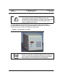
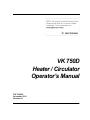
VK 750D Heater / Circulator Operator’s Manual P/N 70-9005 November 2010 Revision H Limitation of Liability The information in this document is subject to change without notice. Varian, Inc. makes no warranty of any kind with regard to this material, including, but not limited to, the implied warranties or merchantability and fitness for a particular purpose. Varian, Inc. shall not be liable for errors contained herein or for incidental consequential damages in connection with the furnishing, performance or use of this material. All rights are reserved. Reproduction, adaptation or translation without prior written permission is prohibited, except as allowed under copyright laws. First Edition (November 2010) VK 750D Heater / Circulator Operator’s Manual Part Number 70-9005 Revision H Printed in the United States of America The following terms are trademarks of Varian, Inc.: • • • • • BenchsaverTM BIO-DIS III® Enhancer Cell® Full Flow FiltersTM Peak VesselTM • • • • • Practical Solutions® QA and QAIITM TruCenterTM VanKel® VK® All other trademarks are the property of their respective owners. Varian, Inc. 13000 Weston Parkway Cary, North Carolina 27513-2250 800.229.1108 919.677.1108 Fax: 919.677.1138 www.varianinc.com Copyright (c) 1999 - 2010 by Varian, Inc. Table of Contents Chapter 1 Safety Practices and Hazards 7 Electrical Hazards 8 Other 8 General 10 WEEE Directive 11 Chapter 2 Introduction 13 Conventions Used in this Manual 15 Chapter 3 Installation and Setup 17 Unpacking Your VK 750D 17 Electrical Connections 19 Interfacing to the Dissolution Apparatus 20 Liquid Connections—Single Apparatus Systems 21 Liquid Connections—Dual Apparatus Systems 23 Hidden Key Functions 25 Varian, Inc. Table of Contents Chapter 4 Operation 27 Initial Power Up 27 Priming the System 28 Operation Under VK 7000 / 7010 Control 29 Set Water Bath Temperature 29 Set Time Delay Start 29 Operation Under Apparatus 3 / Apparatus 7 Control Set Water Bath Temperature 30 Set Time Delay Start 30 Operation Under Local Control 31 Over Temp 32 Optional Report Center Printer 32 Setting Date and Time 33 Setting Automatic Printout Interval 33 RS232 Command Set 34 RS232 Connections 35 Chapter 5 Maintenance 37 Periodic Maintenance 37 Monthly 38 Fuse Replacement 38 Chapter 6 Service and Warranty 39 Exclusions and Limitations 40 Obtaining Warranty Service 40 Warranty Limitations 40 Exclusive Remedies 41 Index 43 Tell Us How We Are Doing Varian, Inc. 45 30 List of Figures FIGURE 1. VK 750D Heater / Circulator FIGURE 2. VK 750D Rear Panel 14 19 FIGURE 3. Single Water Bath Connections 21 FIGURE 4. Dual Water Bath Tubing Connections FIGURE 5. VK 750D Keypad 31 FIGURE 6. Report Center Printer 32 FIGURE 7. DB-9 Connector for RS232 Varian, Inc. 35 23 List of Figures This page was intentionally left blank, except for this message. Varian, Inc. Chapter 1 Safety Practices and Hazards The VK 750D has been carefully designed so that when used properly you have an accurate, fast, flexible, and safe instrument. If the equipment is used in a manner not specified by the manufacturer, the protection provided by the equipment may be impaired. Operation of a VK 750D involves the use of aqueous liquids. Unskilled, improper, or careless use of this instrument can create shock hazards, fire hazards, or other hazards which can cause death, serious injury to personnel, or severe damage to equipment and property. Information on safety practices is provided with your instrument and operation manuals. Before using your instrument or accessories, you must thoroughly read these safety practices. Observe all relevant safety practices at all times. Varian, Inc. Page 8 Safety Practices and Hazards VK 750D Heater / Circulator Operator’s Manual Revision H, 11/10 P/N 70-9005 Electrical Hazards The heater / circulator contains electrical circuits, devices, and components operating at dangerous voltages. Contact with these circuits, devices, and components can cause death, serious injury, or painful electric shock. Panels or covers that are retained by fasteners which require the use of a tool for removal may be opened only by Varian-trained, Varian-qualified, or Varian-authorized service engineers. Consult the manuals or product labels supplied with the heater / circulator to determine which parts are operator-accessible. Application of the wrong supply voltage, connection of the instrument to an incorrectly wired supply outlet, or lack of proper electrical grounding can create a fire hazard or a potentially serious shock hazard and could seriously damage the instrument and any attached ancillary equipment. Always use a three-wire outlet with ground connection which is adequately rated for the load. The installation must comply with local, state, and federal safety regulations. Do not connect the instrument to the main power supply until you have made sure that the operating voltage is correctly set for the main power supply in the specific outlet in your laboratory to which the equipment will be connected. Other Other specific warnings and cautions appear in the manuals where appropriate and detail the specific hazard, describe how to avoid it, and specify the possible consequences of not heeding the warning or caution. Warning A ‘Warning’ message appears in the manual when failure to observe instructions or precautions could result in death or injury. Symbols depicting the nature of the specific hazard are also placed alongside warnings. Varian, Inc. Revision H, 11/10 P/N 70-9005 VK 750D Heater / Circulator Operator’s Manual Page 9 Safety Practices and Hazards These symbols are also used on warning labels attached to the instrument. When you see one of these symbols, you must refer to the relevant operation or service manual for the correct procedure referred to by that warning label. The meaning of the symbols that appear alongside warnings in this manual are as follows: Electrical shock Caution Refer to accompanying documents Read all warnings and cautions carefully and observe them at all times. Caution A ‘Caution’ message appears in the manual when failure to observe instructions could result in damage to equipment (Varian supplied and / or other associated equipment). A ‘Note’ appears in the manual to give advice or information. Varian, Inc. Page 10 Safety Practices and Hazards VK 750D Heater / Circulator Operator’s Manual Revision H, 11/10 P/N 70-9005 Information symbols I 0 Switches main power on Switches main power off Indicates single-phase alternating current Indicates the product complies with the requirements of one or more European Union (EU) directives Indicates specific equipment meets consensus-based standards of safety to provide assurance, required by OSHA, that these products are safe for use in the workplace for North America Indicates that this product must not be disposed of as unsorted municipal waste (see “WEEE Directive” on page 11) General CE Compliant Products The VK 750D has been designed to comply with the requirements of the Electromagnetic Compatibility (EMC) Directive and the Low Voltage (electrical safety) Directive (LVD) of the European Union. Varian has confirmed that each product complies with the relevant directives by testing a prototype against the prescribed European Norm (EN) standards. Varian, Inc. Revision H, 11/10 P/N 70-9005 VK 750D Heater / Circulator Operator’s Manual Page 11 Safety Practices and Hazards Proof that a product complies with the directives is indicated by: • the CE Marking appearing on the rear of the product. • the documentation package that accompanies the product containing a copy of the declaration of conformity. This declaration is the legal declaration by Varian that the product complies with the directives and also shows the EN standards to which the product was tested to demonstrate compliance. The declaration of conformity is signed by the representative of the manufacturing plant. cTUVus - U.S. and Canadian Product Approvals The VK 750D has been designed to comply with North American safety requirements. This product has been tested and certified for the North American market by TUV Rheinland of North America, Inc. The TUVus mark signifies that this product has been tested to U.S. standards and certified for the U.S. market. The cTUV mark signifies that this product has been tested to Canadian standards and certified for the Canadian market. When the two marks are coupled, the cTUVus mark signifies that this product has been tested to standards and certified for both markets. WEEE Directive All Varian products that are subject to the WEEE directive shipped after August 13, 2005 are compliant with the WEEE marking requirements. Such products are marked with the “crossed out wheelie bin” WEEE symbol shown on page 10 in accordance with European Standard EN 50419. This symbol on the product or on its packaging indicates that this product must not be disposed of as unsorted municipal waste. The separate collection and recycling of your waste equipment at the time of disposal will help to conserve natural resources and ensure that it is recycled in a manner that protects human health and the environment. For more information on collection, reuse, and recycling systems, please contact your local/regional waste administration, your local distributor, or Varian, Inc. Varian, Inc. Page 12 Safety Practices and Hazards VK 750D Heater / Circulator Operator’s Manual Revision H, 11/10 P/N 70-9005 This page was intentionally left blank, except for this message. Varian, Inc. Chapter 2 Introduction The VK 750D Heater / Circulator has been designed for precise temperature control of your dissolution water bath with a range from ambient to 55 C and a precision of 0.1 C. The operating parameter values can be set and monitored either from the front panel of the instrument or with the keypad of your VK 7000 / 7010 Dissolution Apparatus. An interface cable interconnects the units enabling them to communicate with each other. The temperature is shown on a large, easy-to-read digital display, and the instrument status is continuously indicated on individual LEDs. For the highest accuracy, the VK 750D can be used with an optional plug-in remote temperature probe for direct monitoring of the water bath temperature. This probe is supplied with all VK 7000 / 7010 Dissolution Testing Stations as a standard accessory. As an alternative, the temperature probe inside the internal tank is used for temperature control. For easy automation, all functions can be controlled and monitored via RS232 with both DB-9 and RJ-11 connectors provided on the rear panel. Varian, Inc. Page 14 Introduction VK 750D Heater / Circulator Operator’s Manual Revision H, 11/10 P/N 70-9005 Warning The equipment contains electrical circuits, devices, and components operating at dangerous voltages. Contact with these circuits, devices, and components can cause death, serious injury, or painful electric shock. The optional Report Center Printer gives you a printout of the system status at user-selectable time intervals for easy documentation of operations. This feature is designed to help you comply with regulatory requirements. FIGURE 1. VK 750D Heater / Circulator Caution Panels or covers that are retained by fasteners which require the use of a tool for removal may be opened only by Varian-trained, Varian-qualified, or Varian-authorized service engineers. Varian, Inc. Revision H, 11/10 P/N 70-9005 VK 750D Heater / Circulator Operator’s Manual Page 15 Introduction Conventions Used in this Manual • Items you are asked to press are in bold. For example, “press 1 on the keypad”. • Key sequences you are asked to press appear like this: CLEAR > 7. Note Remember to return the warranty card. Completing and returning the card ensures your right to protection under the terms and conditions of your warranty. It also enables us to better assist you in the event of any problems. Additionally, it guarantees you will be informed of any issues arising concerning your equipment, such as upgrades, retrofits, or regulatory changes. Varian, Inc. Page 16 Introduction VK 750D Heater / Circulator Operator’s Manual Revision H, 11/10 P/N 70-9005 This page was intentionally left blank, except for this message. Varian, Inc. Chapter 3 Installation and Setup Unpacking Your VK 750D Complete the following steps to unpack your VK 750D: Step 1. Carefully remove all items from the shipping carton. Step 2. Check all items for damage during shipping. If any damage to the instrument is evident, contact both the carrier who delivered the instruments to you and Varian, Inc. Though claims for damage should be filed with the carrier, we will be glad to help you in filing a claim and in getting your system up and running as quickly as possible. Step 3. Check the shipping carton for any items which may have come loose during shipping before discarding or storing the packaging. Varian, Inc. Page 18 Installation and Setup Step 4. VK 750D Heater / Circulator Operator’s Manual Revision H, 11/10 P/N 70-9005 Place the unit on a clear, dry, and level section of the benchtop as close to the dissolution apparatus as possible. At least eight inches (20 cm) of unobstructed space should be available behind the unit for easy access to the rear panel power and liquid connections. As with any electronic apparatus, the area around the instrument must be kept clean and dry. Warning The electrical connection at the back of the equipment is the primary disconnect for the instrument. The heater / circulator should be positioned to allow accessibility to the power cords for easy disconnection. A properly grounded, GFC recommended AC power receptacle rated at 20 amps or higher should be available within six feet (two meters) of the unit. Note If you are interfacing your VK 750D to the VK 7000 / 7010 Dissolution Apparatus, you can place it lengthwise in the space under the rear of the vessel table behind the molded water bath. Situate the heater / circulator so that you have access to the AC power switch (the keypad is not accessible). Should you need to move the heater / circulator, it is necessary to lift the entire dissolution apparatus. Therefore, this option is recommended only if bench space is at a premium. Varian, Inc. Revision H, 11/10 P/N 70-9005 VK 750D Heater / Circulator Operator’s Manual Page 19 Installation and Setup Electrical Connections Warning Ensure the equipment is configured for the voltage supplied. Complete the following steps to make electrical connections: Step 1. Ensure the power switch on the rear panel AC power connector is in the OFF position. See Figure 2, “VK 750D Rear Panel,” below. FIGURE 2. VK 750D Rear Panel Step 2. Connect the power cord to the AC power connector. Warning Because of the wide variety of AC outlet formats around the world, the power cord you need may not be the one supplied with the unit. It may be necessary for you to supply the power cord needed for your country or area. Be sure that any power cord you use meets all local safety regulations and is rated to carry at least 10 amps. Step 3. Plug the other end of the cord into an outlet of the proper voltage. Varian, Inc. Page 20 Installation and Setup VK 750D Heater / Circulator Operator’s Manual Revision H, 11/10 P/N 70-9005 Interfacing to the Dissolution Apparatus If you are using your VK 750D Heater / Circulator with a VK 7000 / 7010 Dissolution Apparatus or Apparatus 3 / Apparatus 7, you can control the VK 750D with the dissolution apparatus keypad. To interface the units, complete the following steps: Step 1. Locate the four-pin cable in the VK 750D accessory kit. Plug one end into the VK 750D rear panel jack labeled INPUT SIGNAL and the other end into the jack on the dissolution apparatus rear panel labeled HEATER/ CIRC. Note When the VK 750D is interfaced to the VK 7000 / 7010, the heater / circulator LED displays a series of dashes (---), indicating it is under remote control and the keypad is locked. Step 2. Ensure the remote temperature probe supplied with the dissolution apparatus is plugged into the rear panel jack labeled BATH TEMP. This enables the dissolution apparatus to monitor and display the water bath temperature while controlling the heater / circulator. Step 3. Set the desired water bath temperature via the dissolution apparatus Main Menu option 3 (Set Temperature on the VK 7000 / 7010 or Bath Temperature on the Apparatus 3 / Apparatus 7). Varian, Inc. Revision H, 11/10 P/N 70-9005 VK 750D Heater / Circulator Operator’s Manual Page 21 Installation and Setup Liquid Connections—Single Apparatus Systems Use the following figure and the steps below to connect a single dissolution apparatus water bath to the VK 750D: FIGURE 3. Single Water Bath Connections Inlet Flow Deflector Outlet Drain Drain Valve Step 1. Locate the two pieces of plastic tubing and the four stainless steel tubing clamps included in the VK 750D tubing kit. Step 2. Slip one end of each piece of tubing over the barbed 90-degree angle adapters in the inlet and outlet bulkhead fittings of the water bath. The inlet fitting is the higher of the two fittings. It has a perforated deflector screen attached on the inside of the water bath (see Figure 3, “Single Water Bath Connections,” above). Slide the tubing as far up on the adapter as possible. Step 3. Slip a tubing clamp over the free end of each piece of plastic tubing and secure each clamp over the barbed angle adapters. To avoid damage to the tubing, do not overtighten. Step 4. Slip the other pair of tubing clamps over the free ends of each piece of tubing and insert the tubing ends onto the inlet and outlet connectors on the rear of the VK 750D. Ensure the tubing connected to the water bath inlet attaches to the VK 750D rear panel connector labeled OUTLET and Varian, Inc. Page 22 Installation and Setup VK 750D Heater / Circulator Operator’s Manual Revision H, 11/10 P/N 70-9005 the tubing connected to the water bath outlet attaches to the VK 750D rear panel connector labeled INLET. Secure the clamps over the inlet and outlet connectors. To avoid damage to the tubing, do not overtighten. Step 5. Double check all connections. Step 6. Fill the water bath with purified water to approximately one inch (2.5 cm) above the inlet fitting. The system is now ready for use. Note Use ultrapure water when possible to minimize scale and mineral buildup. Use algaecide to inhibit mold and bacteria growth. Check the label to ensure the formulation is compatible with the plastic materials used in the water bath construction. The flow paths of the VK 750D are primarily stainless steel and should tolerate most clear water bath formulations. Varian, Inc. Revision H, 11/10 P/N 70-9005 VK 750D Heater / Circulator Operator’s Manual Page 23 Installation and Setup Liquid Connections—Dual Apparatus Systems When using your VK 750D with two dissolution apparatus configured as 12-, 14-, or 16spindle systems, the VK 750D output is divided between the two water baths, then recombined at the inlet. The water baths are also connected via the drains to ensure the water levels are always equal. Use the following figure and the steps below to connect a dual dissolution apparatus water bath to the VK 750D: FIGURE 4. Dual Water Bath Tubing Connections Step 1. Locate the two short lengths of tubing included in the VK 750D tubing kit. Step 2. Slip one end of each piece of tubing over the inlet and outlet connectors on the VK 750D rear panel. Slip a tubing clamp over the free end of each piece of plastic tubing and secure each clamp over the connectors. To avoid damage to the tubing, do not overtighten. Varian, Inc. Page 24 Installation and Setup VK 750D Heater / Circulator Operator’s Manual Revision H, 11/10 P/N 70-9005 Step 3. Slip a tubing clamp over the free end of each piece of tubing and insert one of the supplied Y connectors into the end of each. Secure the tubing clamps over the Y connectors. To avoid damage to the tubing or connectors, do not overtighten. Step 4. Attach a length of tubing to both branches of the Y connector on the VK 750D outlet. Slip a tubing clamp over the free end of each piece of tubing and secure the tubing clamp over the Y connector. To avoid damage to the tubing, do not overtighten. Step 5. Slip another tubing clamp over the free end of each piece of tubing and attach the free end of each piece of tubing to the barbed angle adapters on the water bath inlets. The inlet fitting is the higher of the two water bath fittings and has a perforated deflector screen attached on the inside of the water bath. Secure the tubing clamps. To avoid damage to the tubing, do not overtighten. Step 6. Repeat steps 4 - 5 to attach the VK 750D inlet connectors to the water bath outlets. Step 7. Locate the length of tubing with the drain valve inserted. Slip a tubing clamp over each end and secure the tubing clamps over the drain on the bottom of each water bath. To avoid damage to the tubing, do not overtighten. Step 8. Double check all connections. Step 9. Fill the water baths with purified water to approximately one inch (2.5 cm) above the inlet fitting. The system is now ready for use. Note Use ultrapure water when possible to minimize scale and mineral buildup. Use algaecide to inhibit mold and bacteria growth. Check the label to ensure the formulation is compatible with the plastic materials used in the water bath construction. The flow paths of the VK 750D are primarily stainless steel and should tolerate most clear water bath formulations. Varian, Inc. Revision H, 11/10 P/N 70-9005 VK 750D Heater / Circulator Operator’s Manual Page 25 Installation and Setup Hidden Key Functions Key Sequence Function CLEAR > 1 Use this key sequence to toggle on and off the Report Center Printer (if installed). CLEAR > 4 Use this key sequence to toggle the position of the decimal on the temperature display from one tenth of a degree (0.1 °C) to one one hundredth of a degree (0.01 °C). NOTE: This function does not require that you press ENTER to complete the task. CLEAR > 7 Use this key sequence to enter a different communication port identification number. Enter the appropriate identification number and press ENTER. CLEAR > 8 Use this key sequence to toggle between baud rates of 1200, 2400, 4800, and 9600 BPS. Select the appropriate baud rate by continuing to press CLEAR until the desired selection displays. Press ENTER. Varian, Inc. Page 26 Installation and Setup VK 750D Heater / Circulator Operator’s Manual Revision H, 11/10 P/N 70-9005 This page was intentionally left blank, except for this message. Varian, Inc. Chapter 4 Operation Caution Before operating the circulator, ensure the water bath is filled and the system is fully primed as described in “Priming the System” on page 28. Prolonged operation without water damages the pump and heaters. Initial Power Up Turn on the heater / circulator. Flow begins almost immediately. The unit runs very quietly with only a low hum. If you hear gurgling noises, it is because air remains in the tubing. The air is usually expelled within approximately 30 seconds. If it persists, stop and prime the system as described in “Priming the System” on page 28. Varian, Inc. Page 28 Operation VK 750D Heater / Circulator Operator’s Manual Revision H, 11/10 P/N 70-9005 Priming the System The VK 750D Heater / Circulator has been designed to be self-priming under most conditions. However, it may require some assistance, especially when it is new or has not been used for a period of time, so that the tubing is completely dry. Complete the following steps to prime the unit: Step 1. Ensure the water bath is adequately filled. Step 2. Turn on the pump and tilt up the rear of the unit. This helps the air inside the unit to flow out with its natural buoyancy. You should see and hear the air being expelled through the outlet tubing. Step 3. If more vigorous intervention is required, hold the unit below the level of the benchtop (if the tubing is long enough to allow you to do so) while tilting up the rear. Step 4. Should the unit fail to prime after these steps, contact the Dissolution Systems Service Department or your local Varian representative for assistance. Varian, Inc, Revision H, 11/10 P/N 70-9005 VK 750D Heater / Circulator Operator’s Manual Page 29 Operation Operation Under VK 7000 / 7010 Control Set Water Bath Temperature Step 1. From the system status screen, press MENU. The Main Menu displays. Step 2. Select option 3, Set Temperature. The Select Temperature Set Mode screen displays. Step 3. Select option 1, Set Bath Temp. Step 4. Enter the desired water bath temperature and press ENTER. The newly set temperature displays on the VK 7000 / 7010 status screen. If the actual temperature is lower than the set temperature, the Heater On LED illuminates, indicating the heating element is on. Set Time Delay Start Step 1. From the system status screen, press MENU. The Main Menu displays. Step 2. Select option 3, Set Temperature. The Select Temperature Set Mode screen displays. Step 3. Select option 3, Delayed Bath Heating. Step 4. Enter the desired water bath temperature and press ENTER. Step 5. Enter the desired start time in 24-hour format and press ENTER. Step 6. Enter the desired start date in the appropriate format and press ENTER. The system status screen displays. Varian, Inc. Page 30 Operation VK 750D Heater / Circulator Operator’s Manual Revision H, 11/10 P/N 70-9005 Operation Under Apparatus 3 / Apparatus 7 Control Set Water Bath Temperature Step 1. From the Ready screen, press MENU. The Main Menu displays. Step 2. Select option 3, Bath Temperature. The Bath Temperature Control/Report screen displays. Step 3. Select option 1, Set Bath Temp. Step 4. Enter the desired water bath temperature in xx.x format and press ENTER. The Main Menu displays. If the actual temperature is lower than the set temperature, the Heater On LED illuminates, indicating the heating element is on. Set Time Delay Start Step 1. From the Ready screen, press MENU. The Main Menu displays. Step 2. Select option 3, Bath Temperature. The Bath Temperature Control/Report screen displays. Step 3. Select option 2, Delay Heating. Step 4. Enter the desired start time in 24-hour format and press ENTER. Step 5. Enter the desired start date in the appropriate format and press ENTER. The top line of the display continues to flash until the function is cancelled or until the set date and time are reached. To cancel the delayed heating function, press ESC. The Ready screen displays. Varian, Inc, Revision H, 11/10 P/N 70-9005 VK 750D Heater / Circulator Operator’s Manual Page 31 Operation Operation Under Local Control If you do not interface your VK 750D to a VK 7000 / 7010 Dissolution Apparatus or Apparatus 3 / Apparatus 7, operational parameters are set via the VK 750D keypad as shown below. FIGURE 5. VK 750D Keypad Complete the following steps to set the operational parameters using the VK 750D keypad: Step 1. If you have a remote temperature probe plugged into the VK 750D rear panel, check the Ext. Sensor LED on the front panel. If it is illuminated, the unit is using the remote probe to monitor the actual water bath temperature. If it is not illuminated, the internal sensor is being used. Press EXT./INT. to toggle between the internal and external sensors. Step 2. Set the desired water bath temperature by pressing SET TEMP. The current setting flashes. Press ENTER to accept or key in the desired temperature in xx.x format. Press ENTER. The Heater On LED illuminates if the set temperature is higher than the actual temperature and stays on until the water reaches the desired temperature. It flashes intermittently as the heater approaches the set point. The digital display shows the actual temperature of the circulating water on a continuous basis. Varian, Inc. Page 32 Operation VK 750D Heater / Circulator Operator’s Manual Revision H, 11/10 P/N 70-9005 Over Temp The Over Temp LED illuminates to indicate that the heater has exceeded its 55 °C maximum temperature. This rare event may occur if the water level drops suddenly or if a temperature sensor malfunctions. Shut down power to the instrument and troubleshoot the system. If the source of the problem cannot be located, contact the Dissolution Systems Service Department or your local Varian representative for assistance. Optional Report Center Printer FIGURE 6. Report Center Printer Note Use the hidden key function CLEAR > 1 to enable the Report Center Printer prior to programming it for use. The VK 750D Heater / Circulator is available with an optional Report Center Printer for use as a standalone machine. It provides hard-copy documentation of the unit’s activity, printing the elapsed time, time-of-day, and the actual temperature at user-selectable time intervals. Note The PRINT key toggles on and off the Report Center Printer. Its status is indicated by the Printer On LED on the front panel. Varian, Inc, Revision H, 11/10 P/N 70-9005 VK 750D Heater / Circulator Operator’s Manual Page 33 Operation Setting Date and Time If applicable, complete the following steps to set the correct date and time: Step 1. Press SET CLOCK. The current date flashes in mm/dd/yy format. Step 2. Press ENTER to accept the value displayed or enter the correct date and press ENTER. The current time flashes. Step 3. Press ENTER to accept the value displayed or enter the correct time in 24-hour format (for example, 0900 for 9:00 AM or 1330 for 1:30 PM) and press ENTER. Setting Automatic Printout Interval If applicable, complete the following steps to set the automatic printout interval: Step 1. Press SET PRINT. The current setting flashes in minutes. Step 2. Press ENTER to accept the displayed value or enter the new time interval up to 999 minutes and press ENTER. Varian, Inc. Page 34 Operation VK 750D Heater / Circulator Operator’s Manual Revision H, 11/10 P/N 70-9005 RS232 Command Set The following RS232 codes are available for external communication and/or control of your VK 750D Heater / Circulator via the rear panel RS232 serial ports: Function Mode Command Response Variables Time Read 0123000000 012300hhmm hh = hours mm = minutes Write 013300hhmm Same Read 0123100000 01231mmddy Write 01331mmddy Same Read 0122000000 01220ftttt Write 01320ftttt Same Actual Temp. Read 0122200000 01222ftttt tttt = ttt.t degrees f = 0 Celsius f = 2 Fahrenheit Print Frequency Read 0123200000 0123200mmm mmm = 0-255 min Write 0133200mmm Same Status Read 0125000000 01250vltep Print Instantly Write 0135100000 Same Reset Write 0135000000 Same Date Set Bath Temp. Varian, Inc, mm=month dd = day y = year (last digit) tttt = ttt.t degrees f = 0 Celsius f = 2 Fahrenheit v = VK 7000 control l = low level t = over temp. e = ext. sensor p = printer on 1/0 = Yes/No Revision H, 11/10 P/N 70-9005 VK 750D Heater / Circulator Operator’s Manual Page 35 Operation RS232 Connections Both a standard DB-9 subminiature connector and RJ-11 modular connectors are provided for digital communications with an external controller such as a PC. The pertinent pin connections are detailed in Figure 7, “DB-9 Connector for RS232,” below. FIGURE 7. DB-9 Connector for RS232 Pin 2-Receive Pin 3-Send Pin 5-Ground Control software, which runs in Microsoft Windows®, is available from the Dissolution Systems Service Department. Please contact the Dissolution Systems Service Department or your local Varian representative for more information. Varian, Inc. Page 36 Operation VK 750D Heater / Circulator Operator’s Manual Revision H, 11/10 P/N 70-9005 This page was intentionally left blank, except for this message. Varian, Inc, Chapter 5 Maintenance Periodic Maintenance Warning The instrument contains electrical circuits, devices and components operating at dangerous voltages. Contact with these circuits, devices, and components can cause death, serious injury, or painful electric shock. Periodic maintenance intervals may vary depending on frequency of instrument usage. Varian, Inc. Page 38 Maintenance VK 750D Heater / Circulator Operator’s Manual Revision H, 11/10 P/N 70-9005 Monthly • Clean and dry all surfaces. • Apply an algaecide, bactericide, or any other additive that will not corrode plastic or stainless steel to the water bath or system. • If the water is high in calcium, a 10% solution of white vinegar and water can be used to remove deposits. Do not use this solution more than once a month. • Flush external tubing and check clamps for corrosion. • Clean the external temperature probe with alcohol to remove deposits. Deposits can reduce the measurement accuracy. • If a four-pin communication cable is used, inspect the cable for damage or corrosion. Inspect the power entry module for corrosion and clean it if necessary. Replace the fuse as necessary. Fuse Replacement Caution Panels or covers that are retained by fasteners which require the use of a tool for removal may be opened only by Variantrained, Varian-qualified, or Varian-authorized service engineers. The line fuse is located in a small cassette built into the rear panel AC power receptacle. To remove the line fuse, press the release tab down and slide the entire cassette out of the receptacle. Snap the fuse out of the cassette, replace the fuse, and reinsert the cassette pushing until the release tab snaps back into place. Warning Never replace a fuse with a higher rated fuse. Use only a 10 amp fuse for 115 V power or only a 5 amp fuse for 230 V. Varian, Inc. Chapter 6 Service and Warranty The warranty is provided by Varian, Inc. or one of its authorized representatives. Service and Warranty Information Varian dissolution products carry a one-year warranty on parts and labor. The Dissolution Systems Service Department (or one of its representatives) will, at its option, either repair or replace any mechanical and electrical components in your instrument which prove to be defective. During the first year of warranty coverage, there is no charge for the labor to repair your unit. The Dissolution Systems Service Department (or one of its representatives) will determine the best site to repair the unit, either onsite or returned to Varian, Inc. Any onsite warranty services are provided only at the initial installation point. Installation and onsite warranty services are available only in Dissolution Systems service travel areas. Varian, Inc. Page 40 Service and Warranty VK 750D Heater / Circulator Operator’s Manual Revision H, 11/10 P/N 70-9005 Exclusions and Limitations Excluded from this warranty are expendable or consumable items such as, but not limited to, paddles, baskets, vessels, and acrylic water baths. Also excluded are defects from improper or inadequate maintenance by the customer, user-induced chemical action or contamination, unauthorized modification or misuse, and improper site preparation and maintenance. Operation of software is not warranted to be uninterrupted or error-free. Obtaining Warranty Service To obtain warranty service in the United States, contact the Dissolution Systems Service Department at 800.229.1108 to obtain authorization to return units for repair. At the option of the customer, onsite warranty service is available, but travel charges may be incurred. The customer should prepay all shipping charges for products returned to the Dissolution Systems Service Department (unless otherwise authorized), and Varian, Inc. will pay all charges for return to the customer. Warranty Limitations Varian, Inc. makes no other warranty, either express or implied, with respect to this product. Specifically disclaimed are any implied warranties of merchantability and fitness for a particular use. In no event will Varian, Inc. be liable for any indirect, incidental, or consequential damages arising from the use of this product. This warranty gives you specific legal rights which may vary from state to state or province to province, so you may have other rights and some of these exclusions may not apply to you. Varian, Inc. Revision H, 11/10 P/N 70-9005 VK 750D Heater / Circulator Operator’s Manual Page 41 Service and Warranty Exclusive Remedies The remedies provided herein are the customer’s sole and exclusive remedies. In no event shall Varian, Inc. or its representatives be liable for any direct, indirect, special, incidental, or consequential damages, whether based on contract, tort, or any other legal theory. Some states or provinces do not allow the exclusion or limitation of incidental or consequential damages, so the above limitation or exclusion may not apply to you. Varian, Inc. Page 42 Service and Warranty VK 750D Heater / Circulator Operator’s Manual Revision H, 11/10 P/N 70-9005 This page was intentionally left blank, except for this message. Varian, Inc. Index a apparatus 3 / apparatus 7 control 30 c conventions 15 d db-9 connector for rs232 35 dual water bath tubing connections 23 e electrical connections 19 exclusions 40 exclusive remedies 41 h hazards 7 hidden key functions 25 Varian, Inc. i initial power up 27 installation 17 interfacing to the dissolution apparatus 20 introduction 13 l limitations 40 liquid connections 21, 23 local control 31 m maintenance 37 monthly maintenance 38 o obtaining warranty service 40 operating parameter values 13 operation 27 over temp 32 Index p periodic maintenance 37 priming the system 28 r reader comment form 45 report center printer 32 rj-11 modular connectors 35 rs232 command set 34 rs232 connections 35 s safety practices 7 service 39 setup 17 single water bath connections 21 u unpacking 17 v vk 7000/7010 control 29 vk 750d keypad 31 vk 750d rear panel 19 w warranty 39 warranty limitations 40 Varian, Inc. Tell Us How We Are Doing We listen to our customers. We work hard to make our technical documentation user friendly, and to make the information in our manuals easy to retrieve and use. We’d like you to tell us the kinds of additional information you’d find helpful in our documentation. Your feedback will be carefully considered when we prepare future editions of this manual. This manual should contain the following additional information: The most useful thing about this book is: This manual would be more helpful if: My general impressions of this book are: May we contact you regarding your comments? ____ YES ____ NO (If yes, please write your name, address, and telephone number here.) Please return this form via mail to: Technical Writing / Dissolution Systems, Varian, Inc., 13000 Weston Parkway, Cary, North Carolina 27513-2250 USA. Optionally, you can return this form via fax at 1.919.677.1550. Always, feel free to telephone us to discuss your comments at 1.800.229.1108. VK 750D Heater / Circulator Operator’s Manual P/N 70-9005 Revision H