1
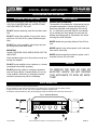
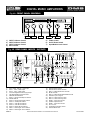
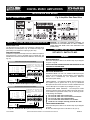
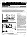
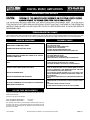
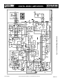
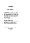
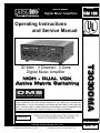
Series DMS
Digital Music Amplifiers
Manual
OM 156
Operating Instructions
and Service Manual
MOH - DUAL VOX
Active Matrix Switching
IMPORTANT NOTE: THIS OPERATING MANUAL IS PROVIDED AS AN INSTALLATION AND
AS AN OPERATING AID. PASO SOUND PRODUCTS, INC. DOES NOT ASSUME ANY
RESPONSIBILITY AS TO ITS ACCURACY AND SHALL NOT BE LIABLE IN TORT OR CONTRACT FOR ANY DIRECT CONSEQUENTIAL OR INCIDENTAL LOSS OR DAMAGE ARISING FROM THE INSTALLATION, USE OR INABILITY TO USE THIS PRODUCT.
CAUTION !
T3030DMA
30 Watt - 3 Channel - 3 Zone
Digital Music Amplifier
TO REDUCE THE RISK OF FIRE OR ELECTRIC SHOCK DO NOT
EXPOSE THIS APPLIANCE TO RAIN OR MOISTURE
Innovation through technology since 1931
© copyright Paso Sound Products, Inc. 1999
Specifications are subject to change without notice
T3030DMA
REV. 1.0
DIGITAL MUSIC AMPLIFIERS
DESCRIPTION AND APPLICATIONS
q 3 Channel Inputs - 3 Zone Outputs
q Wide Frequency Response
Very Low Distortion
q Microphone/Program Input
q Microphone/Telephone Input
q Transformer Balanced Phone Paging Input
q Satellite Receiver Input
With Variable Attenuator
q Rear Panel Port Accepts Standard Module
q Auxiliary or CD Input with Stereo Summing
q Independent Input Controls
Bass and Treble Controls
q Input/Output EQ Link/Mix Buss
q Remote Master Volume
q Addressable Dual Vox System
q Separate Dual Vox Selector
q Direct Muting with Selector
q 600 ohm and 8 ohm 1 Watt
Music on Hold Amplifier
q Zone 1 Amplifier, 1 Watt with Control
q Zone 2 Amplifier, 1 Watt with Control
q NO/NC VOX Relay Terminals
q 24 V DC Regulated Utility
Power Supply Output
q Optional Pre-Paging Chime
q AC Accessory Outlet
q 8 ohm, 25 Volt & 70 Volt Outputs
q Rack Mounting with Optional Kit
Immediately upon receipt of the amplifier, inspect the unit
and shipping container for indications of improper handling
or in transit damage. The equipment was carefully inspect-
SPECIFICATIONS
Power Output:
Distortion:
Frequency Response:
Inputs:
Input 1
Input 2
Input 3
Sensitivity:
Input 1
Input 2
Input 3
Hum & Noise:
Telephone Input:
Input Impedance:
30 Watt RMS
Less than 0.5% THD
20 - 20,000 Hz ± 1 db
Microphone/Telephone
Microphone/Program
Auxiliary/CD
Power Requirement:
Power Consumption:
Terminations:
Housing Finish:
Dimensions:
Mic=1 Mv, Tel=100 Mv
Mic=1 Mv, Program=1 Volt
Aux=200 Mv, CD=360 Mv
Mic -65 db, Aux -75 db
600 ohm Transformer Balanced
Mic= 250 ohm Bal., Tel= 600 ohm Xfmer
Bal., Aux/CD= 47 K ohm, Program= 10K
ohm Bal.,
1 Volt-600 ohm Balanced, 1 Watt-8 ohm
600 ohm-1 Volt, 8 ohm-1 Watt
8 ohm-1Watt
8 ohm, 25 Volt and 70 Volt line
Input 1 Volume, Input 2 Volume, Input 3
Volume, Module Level, Bass, Treble, Input 2
Attenuator, Zone 1 and Zone 2 Level
Controls
Normally Open and Normally Closed
Contact Terminals
24 Volt DC - 100 MA Regulated
Accepts Standard Module
Preamp out, Power Amp in
+/-10 db at 100 Hz and 10 K hz
Dual Vox (Voice Activated) System Direct
Muting with Selector, Inputs Priority Selector
117 Volt, 50-60 Hz
AC=100 VA
Screw Terminals, RCA Jacks
Black
10.5"W., 9.5"D., 3.5"H. (267X242X89 mm)
Net Weight:
11 Lbs (5.0 Kg)
Music on Hold Output:
Zone 1 Output:
Zone 2 Output:
Output Impedance:
Controls:
VOX Relay:
Utility Power Supply:
Accessory Port:
EQ Link/Mix Buss:
Tone Control Action:
Muting/Precedence:
ACCESSORIES
27/3500 - Standard 19” Rack Mounting Kit. Black finish.
Complete with hardware
ed and tested before leaving the factory. Notify the
Transportation Company immediately if any damage is
found. ONLY THE CONSIGNEE CAN FILE A CLAIM WITH
THE CARRIER FOR DAMAGE DURING SHIPMENT. Be
sure to save the carton and packing material as evidence of
damage for the shipper inspection. DO NOT SHIP the unit
back to the factory unless authorized by the factory.
IN TRANSIT DAMAGES ARE NOT COVERED BY THE
PASO WARRANTY.
PAGE 2
© copyright Paso Sound Products, Inc. 1999
Specifications are subject to change without notice
T3030DMA
DIGITAL MUSIC AMPLIFIERS
INSTALLATION AND OPERATION
OPERATING PRECAUTIONS
SAFETY NOTES
BEFORE OPERATING THE AMPLIFIER, BE SURE
YOU FULLY UNDERSTAND ALL INSTRUCTIONS
AND FEATURES OF THE UNIT.
POWER AND GROUNDING
The amplifier is furnished with a three-prong plug as
a standard equipment. Connect the line cord to a
three-wire grounded outlet supplying 120 volts 60
Hz.. If a three-wire grounded outlet is not available,
use a standard two wire adapter. Be sure that the
adapter grounding pigtail is connected to the screw
securing the outlet wall plate.
DO NOT assume anything, read all instructions carefully.
DO NOT connect the amplifier to any power source
other than 120 volts 60 hz. (unless otherwise specified).
NEVER defeat the grounding feature of the AC line
cord.
DO NOT turn on the amplifier until all input and output connections have been made.
NEVER replace fuses unless power cord is removed
from the AC wall outlet.
MOUNTING
ALWAYS PROVIDE GOOD VENTILATION FOR THE
AMPLIFIER.
NEVER install accessories unless the power cord is
removed from the AC wall outlet.
Good ventilation allows air to flow under, around and
through the amplifier.
CAUTION
DO NOT mount amplifier into a container or a closed
unventilated closet while operating.
TO REDUCE THE RISK OF FIRE OR
ELECTRIC SHOCK DO NOT EXPOSE
THIS APPLIANCE TO RAIN OR MOISTURE
DO NOT place any object or accessory equipment
such as Tuners, Mixers, Cassette Decks, etc. on top
of the amplifier. Obstructing or closing the cabinet
ventilation openings may cause overheating.
RACK MOUNTING
A) Procure the optional accessory Rack Mount Kit.
B) Turn amplifier up side down and remove the four rubber feet by unscrewing the four holding screws.
C) Remove three screws on each side of the amplifier holding the amplifier cover.
D) Install the rack kit brackets by using the self-tapping screws provided and the screws removed as per C.
Fig. 3 - Rack Kit Mounting
DIGITAL MUSIC AMPLIFIER
.
.
1.
. 5. .6
4
3
2
0
.
.
INPUT 1
.7 3.
.8 2.
. .
19 1
0
. 5. .6
4
0
.
.
INPUT 2
.7 3.
.8 2.
. 1.
19
0
. 5. .6
4
.
0
.
INPUT 3
.7
.8
.
19
0
.
.
4.
-
. 0. .1
1
2
3
5
.
.
BASS
.2
.3
.4
5
+
.
.
4.
-
. 0. .1
1
2
3
5
.
.2
.3
.4
.5
+
TREBLE
O
POWER
3015rack
T3015/3030DMA
SPECIFICATIONS ARE SUBJECT TO CHANGE WITHOUT NOTICE
PAGE 3
DIGITAL MUSIC AMPLIFIERS
Fig. 4A - FRONT PANEL CONTROLS
DIGITAL MUSIC AMPLIFIER
0
MODULE
4. . .6
5
3
2
.
.
1
.
0
.7 3 .
. 8 2.
.9 1 .
. 10
.
4. . .6
4. . .6
5
INPUT 1
0
5
.7
.8
.9
. 10
.
INPUT 2
3
2
.
.
1
.
0
1
.7
.8
.9
. 10
.
2
3
.
. 0. . 1
.
.
4
-5
.
.
INPUT 3
2
3
.
. 0. . 1
.2
.3
.4
.
4
.
-5
5+
BASS
. 5+
.
TREBLE
O
POWER
7
3015Bcont
1
1)
2)
3)
4)
1
.2
.3
.4
2
3
INPUT 1 Volume Control
INPUT 2 Volume Control
INPUT 3 Volume Control
Bass Control
4
5
6
5)
6)
7)
Treble Control
On-Off Power Switch
Input Module Level Control
15)
16)
17)
18)
19)
20)
21)
22)
23)
24)
25)
26)
27)
28)
EQ LINK Switch ON-OFF
Remote Volume Control Terminals
INPUT 1 - Balanced MIC/TEL Terminals
MUTE Terminals
INPUT 2 - Balanced MIC/PROGRAM Terminals
Attenuator Input 2 Program
INPUT 2 - Stereo Summing Jacks
INPUT 3 - Stereo Summing Jacks
ZONE 2 - Output Level Control
Speaker Output Terminals
ZONE 1 - Output Level Control
AC LIne Fuse
Unswitched AC Auxiliary Socket
Standard Module Port
Fig. 4B - REAR PANEL INPUTS - OUTPUTS
1)
2)
3)
4)
5)
6)
7)
7A)
8)
9)
10)
11)
12)
13)
14)
Zone 1 MOH - 600 ohm, 1 Volt Output
Zone 1 - 8 ohm, 1 Watt Output
Zone 2 - 8 ohm, 1 Watt Output
24 Volt DC Regulated Power Supply Output
VOX Relay NO/NC Contact Terminals
PREAMP OUT/MIX BUSS
INPUT 1 - Microphone/Telephone Selector
POWER AMP IN
INPUT 2 - Microphone/Program Selector
INPUT 3 - Auxiliary/CD Selector
INPUT 1 - VOX ON-OFF Selector
INPUT 2 - VOX ON-OFF Selector
INPUT 2 - MUTE ON-OFF Selector
ZONE 1 - AUX/Program Source Selector
ZONE 2 - AUX/Program Source Selector
PAGE 4
SPECIFICATIONS ARE SUBJECT TO CHANGE WITHOUT NOTICE
T3015/3030DMA
DIGITAL MUSIC AMPLIFIERS
INSTALLATION AND WIRING
INPUT CONNECTIONS
Fig. 5 Amplifier Rear Panel View
Z
O
N
E
1
T3015DMA
15 W RMS
76 VA
ZONE 1
ZONE 2
Z
O
N
E
2
E
Q
L
I
N
K
POWER
PREAMP
IN
OUT
EQ LINK
INPUT
3
Off
(MIX BUSS)
INPUT On
2
ZONE 2
ZONE 1
L
R
LINE FUSE 1.6 A 250 V
INPUT 1 SETTING AS A MICROPHONE INPUT
MICROPHONE TYPE
The Microphone Input accepts Low Impedance (250-600 ohm)
Microphones. The Microphone may be a balanced output type
(three wire) or an unbalanced output type (two wire).
PASO MICROPHONES
All PASO low impedance Microphones have a balanced output for
best performance. Connect the RED lead to terminal HOT, the
WHITE lead to terminal COM and the SHIELD to terminal G (see
Fig. 5A).
THREE LEADS BALANCED MICROPHONE WIRING
INPUT 1 - Switch Setting
I
N
P
U
T
1
I
N
P
U
T
2
MIC
MIC
TEL
Prog
I
I
I
I
N N N
N
P P
P
P
U
U
U
U
T T
T
T
1 2
2
3
Vox Vox Mute
Aux
On On On
CD
Off Off Off
Z
O
N
E
1
Z
O
N
E
2
E
Q
The microphone lead color refers to Paso
Microphones only.
When using other
microphone brand refer to instructions packed
with the unit.
L
I
N
K
INPUT 1
RVC
MIC/TEL
BALANCED
REM
VOLUME
INPUT 2
MIC/PROG
BALANCED
INPUT
3
Off
INPUT On
2
G
MUTE
COM HOT MUTE G
COM HOT REMOTE
VOL
SHIELD
3015Bmicbal
MIC
Lo Z
RED
TWO LEADS UNBALANCED MICROPHONE WIRING
INPUT 1 - Switch Setting
I
N
P
U
T
2
MIC
MIC
TEL
Prog
I
I
I
I
N N N
N
P P
P
P
U U U
U
T T
T
T
1 2
2
3
Vox Vox Mute
Aux
On On On
CD
Off Off Off
Z
O
N
E
1
Z
O
N
E
2
E
Q
L
I
N
K
INPUT
3
Off
INPUT On
2
The microphone lead color refers to Paso
Microphones only.
When using other
microphone brand refer to instructions packed
with the unit.
INPUT 2
MIC/PROG
BALANCED
G
MUTE
INPUT 1
RVC
MIC/TEL
BALANCED
REM
VOLUME
COM HOT MUTE G
COM HOT REMOTE
VOL
SHIELD
3015Bmicunbal
MIC
Lo Z
RED
Fig. 5B - Unbalanced Microphone Input 1 Wiring
T3015/3030DMA
INPUT SWITCH SETTING
SET INPUT 1 SWITCH TO MIC
WIRING
MICROPHONE INPUT
Attach the microphone leads to the terminal strip as per diagram
in Fig 5A or Fig. 5B.
DO NOT GROUND THE MICROPHONE CABLE SHIELD TO THE
CHASSIS OF THE AMPLIFIER
CABLE
BALANCED MICROPHONE
IMPORTANT NOTE: The use of an unbalanced Microphone (two
leads) is not recommended. For best results in a PA Application
always use a Unidirectional, Low Impedance, Balanced
Microphone (three leads).
WHITE
Fig. 5A - Balanced Microphone Input 1 Wiring
I
N
P
U
T
1
CAUTION: TO PREVENT POSSIBLE DAMAGE TO
SPEAKERS OR THE AMPLIFIER ALL INPUT CONNECTIONS MUST BE MADE WITH THE AMPLIFIER OFF
(POWER OFF).
CABLE LENGTH - If the distance between the Microphone and
the Amplifier Input is greater than 15 ft (4.5 m) a Balanced
Microphone must be used. Use a two conductor shielded wire and
connect Microphone to Amplifier as per Diagram in Fig. 5A.
MICROPHONE CABLE ROUTING - The Microphone Cable
should be carefully routed. Improper Cable routing will cause spurious oscillations, regenerative noises, hum, etc. that may permanently damage the Amplifier.
l Do not route cable next to power lines.
l Do not route cable near or over Fluorescent Fixtures.
l Do not route cable next to Speaker Wires.
l Do not install cable inside Power Line Conduits.
l Avoid the use of staples that may penetrate the cable.
UNBALANCED MICROPHONE
Attach the Microphone leads to the terminal strip as per diagram
in Fig 5B.
Be sure the cable length does not exceeds 15 Ft. (4.5 m).
SPECIFICATIONS ARE SUBJECT TO CHANGE WITHOUT NOTICE
PAGE 5
DIGITAL MUSIC AMPLIFIERS
INSTALLATION AND WIRING
OUTPUT CONNECTIONS
CONSTANT VOLTAGE DISTRIBUTION SYSTEMS
25 VOLT AND 70 VOLT CONSTANT VOLTAGE DISTRIBUTION SYSTEMS - In applications requiring a large number of speakers that
are located at a far distance from the amplifier a 25 Volt or a 70 Volt Constant Voltage method is most widely used.
MAIN ADVANTAGES IN USING THE HIGH IMPEDANCE METHOD
1) All speakers are connected in parallel usually on to a single speaker line.
2) The Amplifier Output Voltage is constant over a very wide range of load impedance.
3) The Amplifier Output Voltage remains practically constant if loudspeakers are connected or disconnected from the line.
4) Different acoustic power can be allocated in each area as required by using the power taps on the speaker line transformer.
5) Since the system provides a higher voltage at a lower current, resistive loss in the cable is reduced resulting in a higher efficiency.
6) Calculations of the output power needed and the speaker power requirements are simple and easily accomplished.
WIRING
spk 1
spk 2
70 Volt
Transformer
spk 3
70 Volt
Transformer
spk 4
70 Volt
Transformer
70 Volt
Transformer
5
2.5
0.6
1.25
0
5
2.5
1.25
0
0.6
5
2.5
1.25
0
0.6
5
2.5
1.25
0
0.6
INSTALLATION TIPS
1) Determine the amount of speakers required for the
installation and their location.
2) Choose the power output needed for each speaker (typically 1.25 Watt for background music applications and 510 Watt for paging horns).
3) Add all the speaker taps wattage (see Fig. 11) and be
sure that the total power needed does not exceed the
Rated RMS Power Output of the Amplifier
4) Procure a jacketed, two conductor cable of at least 18
gauge.
5) Carefully route cable starting with the farthest speaker
in the system and until all speakers are reached by the
cable and terminating at the Amplifier location. The best
cable route is determined by the individual application.
6) Connect each speaker in accordance to the power output required by selecting the corresponding Power Tap.
IMPORTANT NOTE: Make sure that the unused stripped
power tap wires are INDIVIDUALLY INSULATED and do
not touch each other or an amplifier overload will occur.
7) Connect the speakers cable to the 25 Volt or 70 Volt and
COM output terminals of the Amplifier, turn the system on
and balance the various speakers accordingly. The selection of the Constant Voltage (25 Volt or 70 Volt) is determined by the speakers used. All speakers must operate at
the same constant voltage and cannot be mixed.
Total Speaker Load Calculation
TL = SPK1+SPK2+SPK3+SPK4
TL =1.25+1.25+2.5+5 = 10 Watt
COM
8
25V
70V
spkout05
Fig. 11 - 70 Volt Constant Voltage System Diagram
spk 1
70 Volt
Transformer
5
2.5
PASO VC20 ATTENUATOR
1.25
RED
0.6
0
spk 3
0.6
BLUE
BLACK
spk 2
70 Volt
Transformer
5
spk 4
2.5
1.25
70 Volt
Transformer
70 Volt
Transformer
0
5
2.5
1.25
0
TL = SPK1+SPK2+SPK3+SPK4
0.6
5
2.5
1.25
0
0.6
Total Speaker Load Calculation
LINE ATTENUATORS
In installation requiring that one or a group of speakers
have an independent level control a Line Attenuator can
be utilized. The Fig. 11A shows the use of a PASO model
VC20 - 20 Watt Attenuator used to control two speakers
simultaneously. The wire colors pertain to the VC20, if
other types are used follow the directions supplied with the
unit.
By turning the stepped switch of the VC20 the level of
speakers SPK 1 and SPK 2 can be adjusted, up or down,
from 0 (no output) to the maximum output determined by
the tap utilized on the speakers (in this example 2.5 Watt
max.). Speakers SPK 3 and SPK 4 are not effected.
TL = 2.5+2.5+2.5+2.5 = 10 Watt MAX.
COM
8
25V
70V
spkout06
Fig. 11A - Using a Line Attenuator Diagram
T3015/3030DMA
NOTE: The total power required for all the speaker or
speakers to be controlled should not exceed the Power
Handling rating of the Attenuator. Example: the maximum
load for the VC20 is 20 Watt.
SPECIFICATIONS ARE SUBJECT TO CHANGE WITHOUT NOTICE
PAGE 11
DIGITAL MUSIC AMPLIFIERS
MAINTENACE AND SERVICE
CAUTION !
REMOVAL OF THE AMPLIFIER COVER PRES ENTS AN ELECTRICAL S HOCK HAZARD
ALWAYS REMOVE THE POWER CORD FROM THE AC WALL OUTLET
THE SERVICING INSTRUCTIONS ARE FOR USE BY QUALIFIED PERSONNEL ONLY. TO AVOID ELECTRIC SHOCK DO NOT PERFORM ANY SERVICING OTHER THAN THAT CONTAINED IN THE OPERATING
INSTRUCTIONS UNLESS YOU ARE QUALIFIED TO DO SO. REFER SERVICING TO QUALIFIED SERVICE
PERSONNEL ONLY.
TROUBLESHOOTING CHART
This Troubleshooting Chart is provided to the installer as an aid in locating and correcting possible problems that may arise during installation or after use. This chart should only be used by qualified personnel trained in repair and maintenance of electrical apparatus.
PROBLEM SYMPTOMS
PROBABLE CAUSE
1)
2)
3)
4)
5)
6)
NO VOLTAGE PRESENT AT AC OUTLET.
AC LINE FUSE OPEN.
DEFECTIVE OR OPEN POWER CORD.
POWER SWITCH INOPERATIVE.
POWER TRANSFORMER WINDING OPEN.
POWER INDICATOR DEFECTIVE OR DISCONNECTED.
POWER INDICATOR GLOWS BUT THERE IS NO OUTPUT
FROM THE AMPLIFIER.
1)
2)
3)
4)
INPUT CONTROLS SETTING NOT ADJUSTED PROPERLY.
SPEAKER WIRES SHORTED.
SPEAKER(S) LINE INTERRUPTED.
MICROPHONE OR PROGRAM SOURCE INTERRUPTED.
LOUD HUM OR CRACKLING SOUND FROM THE SPEAKERS.
1) MICROPHONE INPUTS INCORRECTLY WIRED.
2) OPEN GROUND OR SHIELD IN INPUT CABLES.
3) SPEAKER TERMINALS SHORTED TO CHASSIS GROUND.
AMPLIFIER IS COMPLETELY DEAD.
POWER INDICATOR DOES NOT GLOW.
OUTPUT LEVEL LED’S GLOW CYCLICALLY
SOUND IS INTERMITTENT.
SOUND IS DISTORTED AND SCRATCHY.
ACOUSTIC FEEDBACK OR LOUD SQUEAL OCCURS WHEN
AMPLIFIER IS TURNED ON.
1) SPEAKER LINE SHORTED.
2) ONE OR MORE SPEAKER OR LINE TRANSFORMER SHORTED.
3) OUTPUT IMPEDANCE LOAD MISMATCHED WITH AMPLIFIER
OUTPUT IMPEDANCE SETTING (OVERLOAD).
4) IN CONSTANT VOLTAGE SYSTEMS (25-70 V) THE TOTAL LOAD
POWER REQUIREMENT EXCEEDS THE AMPLIFIER POWER RATING (OVERLOAD).
5) EXCESSIVELY HIGH SETTING OF ONE OR MORE VOLUME CONTROLS.
1) MICROPHONE IS LOCATED TOO CLOSE OR IS FACING SPEAKERS.
2) VOLUME CONTROL SETTING TOO HIGH.
3) TONE CONTROLS SHOULD BE SET IN THE CUT RANGE.
AC LINE FUSE REPLACEMENT
CAUTION: TO REDUCE THE RISK OF FIRE REPLACE ONLY WITH THE
SAME TYPE OF FUSE
Procure a Fuse Type: 5mm Diameter
Model T3015DMA FUSE RATING =
Model T3030DMA FUSE RATING =
1.6 A 250 V
2 A 250 V
Turn amplifier power switch to the Off position. Remove power cord from
AC outlet. Insert the tip of a screwdriver inside the Fuse Holder Cap and
remove the fuse by unscrewing the cap. Replace Fuse and screw the cap
back onto Fuse Holder.
T3015/3030DMA
SPECIFICATIONS ARE SUBJECT TO CHANGE WITHOUT NOTICE
PAGE 15
Fig. 20 - Schematic Diagram Section 1
DIGITAL MUSIC AMPLIFIERS
PAGE 20
SPECIFICATIONS ARE SUBJECT TO CHANGE WITHOUT NOTICE
T3015/3030DMA
Fig. 21 - Schematic Diagram Section 2
DIGITAL MUSIC AMPLIFIERS
T3015/3030DMA
SPECIFICATIONS ARE SUBJECT TO CHANGE WITHOUT NOTICE
PAGE 21
DIGITAL MUSIC AMPLIFIERS
CUSTOMER SERVICE
REPLACEMENT PARTS
REPAIR SERVICE
REPLACEMENT PARTS
Please provide complete information when you request replacement parts from either the Factory or a Paso Authorized
Distributor. Be certain to include the Part Number and
Description as it appears on the parts list, the Model Number of
the unit and if possible the Serial Number and the date of purchase of the unit. Replacement parts inventory is maintained
specifically to repair Paso products. Part sales for other reasons
or applications will be declined.
REPAIR SERVICE
Repair service for out of warranty Paso products may be
obtained form your local Paso distributor or any other qualified
repair station.
ORDERING FROM THE FACTORY
Print all information on a purchase order form and mail to:
PASO SOUND PRODUCTS, INC.
4750 Goer Drive - Building F
NORTH CHARLESTON, SC 29406
IN WARRANTY REPAIR SERVICE
Call or write the Factory to obtain an authorization to return
the product for repairs.
Be sure to include the following:
- Paso part number
- Part description
- Quantity required
- Model number of the unit
- Serial number of the unit
- Your payment or your authorization for COD shipment for parts
not covered by the Warranty or if your company has a current
account with the factory
In warranty repairs must be returned to the Factory.
Prior authorization must be obtained from the Factory.
Products received without authorization will be refused by our
Receiving Dept..
Pack the equipment in the original carton or in a strong carton
with at least THREE INCHES of resilient packing material on all
sides, top and bottom. Seal the carton with reinforced tape and
mark it FRAGILE on at least two sides. Remember, the Carrier
will not accept liability for shipping damages if the unit is improperly packed.
EQUIPMENT RECEIVED IN DAMAGED CONDITION DUE TO
POOR PACKING WILL BE REFUSED AND THE WARRANTY
COVERAGE IS AUTOMATICALLY VOIDED.
The Paso Sound Limited Warranty provides:
RETAIN ORIGINAL IN WARRANTY PARTS UNTIL YOU
RECEIVE REPLACEMENTS. PARTS THAT SHOULD BE
RETURNED TO THE FACTORY WILL BE LISTED ON YOUR
PACKING SLIP.
For your convenience replacement parts are also available
through Paso Authorized Distributors and Dealers nation wide.
Obtain a location list directly from the Factory or your regional
Paso Representative.
The examination of the returned product must disclose in our
judgement, a manufacturing defect. The warranty does not
extend to any product that has been subject to misuse, neglect,
accident, improper installation or where the serial number of the
product has been removed or defaced.
Ship via insured prepaid United Parcel Service or Parcel Post to:
PASO SOUND PRODUCTS, INC.
4750 Goer Drive - Building F
NORTH CHARLESTON, SC 29406
ATT. SERVICE DEPARTMENT
The equipment will be returned freight prepaid after repairs.
TECHNICAL CONSULTATION
- Need help with your installation ?
- Need help with the operation of the unit ?
- Need help with a repair ?
Call or write for assistance. You will find our Technical Dept..
eager to help or assist you with any technical problem you may
have encountered except “`Customizing'' for a unique application.
The effectiveness of our consultation service depends on
the accuracy of the information you furnish.
Be sure to tell us:
- The Model and Serial number of the unit
- The date of purchase
- An exact description of the difficulty
- All you have done in attempting to correct the problem
Call our toll-free phone number:
Be sure to include the following:
- Your name and address
- Date of purchase and copy of invoice
- A brief description of the difficulty
- A return address shipping label
OUT OF WARRANTY REPAIR SERVICE
Follow return instructions as per in warranty repair service. Prior
to performing all necessary repairs, you will be advised of the
charges and at that time a written authorization by you will be
required including authorization to return the equipment COD for
the service and shipping charges. This will avoid unnecessary
delays in returning the equipment to you.
1-800 231 3034
Printed in USA
Manual OM
PAGE BACK