1
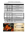
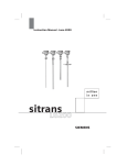
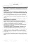
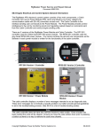
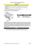
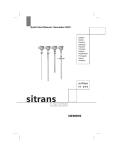
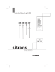
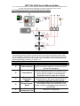
MTS-T4-LG200 Service Manual Update
If you have any further questions or concerns regarding this service manual update please contact RigMaster Power’s
Technical Support Department at (888) 208-3101 before proceeding with service or repairs.
1.15 Coolant Temperature Controlled Electric Fan Switch
Figure 1-40
NOTE
Please note that this is a representative schematic and is intended to illustrate the
interrelationship between the AC electrical system and the engine temperature switch which
are both capable of activating the electric fan. There are diodes in these electrical circuits that
are not represented in this schematic; detailed circuit information should be obtained through
the wiring schematic in section 1.14, Figure 1-39
Air Conditioning Electrical Circuit
Location
Component
A
Cabin Controller
B
Power Module
C
Evaporator
Thermostatic
Switch
D
Binary Pressure
Switch
E
7.5 Amp
Compressor Fuse
Operation
Houses the climate control thermostat and sends
signals to the power module to control the ON/OFF
cycle of the compressor
Receives inputs from the cabin controller and
outputs voltage through the J1 connection point
(green wire, pin number 2) to the evaporator
thermostatic switch to power the AC system
Monitors the temperature of the evaporator and
regulates power to the binary pressure switch to
prevent the evaporator core from freezing
Allows voltage to pass to the compressor and AC
controlled fan relays when the pressure in the
system is within an acceptable range (between 28
and 450 PSI)
Fuses the AC compressor
MTS-T4-LG200 Service Manual Update
If you have any further questions or concerns regarding this service manual update please contact RigMaster Power’s
Technical Support Department at (888) 208-3101 before proceeding with service or repairs.
Continued from 1.15
Location
F
G
H
I
J
Component
Compressor
Operation
Receives its power from the binary switch through
7.5 amp in-line fuse
Receives its signal from the power module whenever
the air conditioning is called for
AC Controlled Fan
Relay 1
35 Amp Electric
Fuses the electric radiator fan
Fan Fuse
AC Controlled Fan Receives its signal from the power module whenever
Relay
the air conditioning is called for
35 Amp Electric
Fuses the electric bottom fan
Fan Fuse
Engine Temperature Switch Circuit
Outputs signal voltage to the engine temperature
Coolant
controlled radiator fan relay when the engine
K
Temperature
Switch
reaches 195°F
Receives
its signal from the coolant temperature
Engine
switch
ensuring
that the electric radiator fan
Temperature
L
operates when engine temperature rises above
Controlled Fan
Relay
the switches threshold.
35 Amp Electric
Fuses the electric fan
M
Fan Fuse
N
Electric
Radiator Fan
Cools the radiator and the condenser
O
Electric
Bottom Fan
Circulates air through the unit when AC
is called for
Figure 1-41
Electric Fan
Temperature Switch
Figure 1-42
•
•
Water Pump
Switch is open under 195 °F
Switch is closed over 195 °F
Electric Fan Temperature Switch
[RP7-214]