1
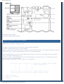
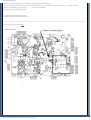
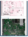
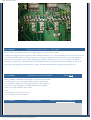
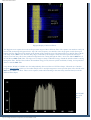
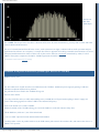
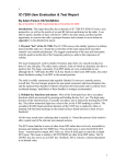
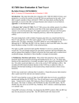
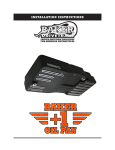
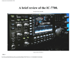
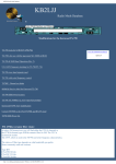
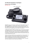
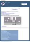
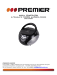
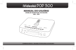
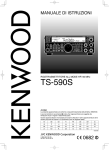
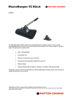
KB2LJJ Radio Mods Database
KB2LJJ
www.r6-ru4montesecchieta.it
IZ5CCV
Home
Radio Mods Database and Manuals
Modifications for the Icom IC-756PRO
Expand tx-freqeuncy for the IC756-PRO
ICOM IC-756PRO CW Filter Shape Selection
Eliminate an adjacent channel noise problem (QST mod for IC756PRO)
50 Mhz 100 Watts Adjustment
50 Mhz 100 Watts adjustement
Open the bottom lid of the radio.
Looking on Main board for the tiny potentiometer at the bottom side of the transceiver.
There are only numbers marked on the board.
You have to look in the service manual to find out what number is correct.
R-509 is the one to adjust the 6m 100W
The R-509 is located on the "Main Unit".
R-509 is the proper adjustment point but you need to make sure you follow
the proper procedure per the service manual.
http://www.kb2ljj.com/data/icom/ic-756pro.htm (1 di 12)23/08/2009 22.38.09
KB2LJJ Radio Mods Database
By Kevin McClinton, W7JRL
Icom Technical Support Representative
Expand tx-freqeuncy for the IC756-PRO
Author: Hans , PA3HGT - [email protected]
You need a very fine solder iron to remove the 3 diodes from the main board!
You have to remove the bottom cover of the 756PRO.
When you removed the cover and you have the backside of the 756-PRO facing you , you can locate the dsp-box on the leftside (the shiny-box). You have lift the dsp-box (with care !) out of the main board.
After removing the dsp , you can see a row of diodes with some spaces. You can see on the right of the row the number
"3751" , that diode is already missing , hi.
You have to remove 3 small diodes located on the left side of number "3751" (diodes 3752 , 3753 and 3754) when you
have a version "#03" Icom IC756-PRO.
When you have a version "#02" : remove diode 3751 , 3752 and 3753 !
R R R I I I X X I I X X I I I X
3
3
3
3
7
7
7
7
6
6
5
5
3
0
5
1
diode-row IC756-PRO version "#03"
before modification .
R R R I I I X X I I X X X X X X
R R R I I I X X I I X X I X X X
after version "3" mod.
after version "2" mod.
I = diode installed
X = diode not installed
R = resistor
http://www.kb2ljj.com/data/icom/ic-756pro.htm (2 di 12)23/08/2009 22.38.09
KB2LJJ Radio Mods Database
Trouble to find the diode-row ? It's about 1/2 inch located under the CPU.
If you can't find out the version of your 756-PRO (#02 or #03) , look at the topside of the box .( see white sticker).
If there's something going wrong .............. I've no responsibility
This info is from a Icom-infosheet .
73 van Hans/PA3HGT uit Yerseke
[email protected]
Here is two pictures from astra.
http://www.kb2ljj.com/data/icom/ic-756pro.htm (3 di 12)23/08/2009 22.38.09
KB2LJJ Radio Mods Database
Here is another two photo from kb1vi
http://www.kb2ljj.com/data/icom/ic-756pro.htm (4 di 12)23/08/2009 22.38.09
KB2LJJ Radio Mods Database
User comment
Making 756P continuous Xmit 1.6 - 29.999 MHz
Mods desired to use 756P as Xverter on 24 MHz which is out of its stock Tx range.
I followed the suggested steps for making 756P continuous Xmit from 1.6 - 29.999. Bottom cover removed by 10 screws
(6 on bottom and 4 on sides), no need to remove feet. CPU box is connected to mother board via two multi-conductor
connectors. Easy to gently "rock" it back and forth, pops right off. Diodes on my Ver #2 were instantly identifiable.
Heated one end, used very small blade knife to lift desoldered end. Left diodes connected and "hanging" by other end.
Total time required approx 10 minutes. Piece of cake. No observable reduction in operation upon firing it up.
User comment
Extended Xmit including 30-60MHz
From: K3CW
On my 756PRO, I found that leaving diode 3753 in place (and all other
locations from 3751 to 3756 empty) enables transmit continuously
from 1.6MHz to 60MHz. The mod suggested above enables transmit
from 1.6 to 30 but transmitting is still disabled from 30 to 50MHz.
I think it's an older 756PRO, serial #1090.
Note:
1) Experiment at your own risk. I am! :)
2) Use a dummy load not an antenna.
User comment
IC 765 Pro Freq Mod
http://www.kb2ljj.com/data/icom/ic-756pro.htm (5 di 12)23/08/2009 22.38.09
From: NL7HQ - Derek Edmondson
KB2LJJ Radio Mods Database
After experimenting with several of the diodes (D3751 thru D 3756), this is what I found on my 756 Pro (I) (S/N
01850):
Removal of 3751, 3752, 3753 gives TX 1.6 MHz to 30 MHz, plus normal 50 MHz to 54 MHz. Removal of 3756
(3754 and 3755 were already gone from factory) killed the TX on 50 MHz to 54 MHz. Reinstalling 3756 restored
50 MHz to 54 MHz. Reinstalling 3753 opened TX from 100 kHz to 60 MHz continuous.
However, be very careful from 30 MHz to 50 MHz, as the block diagram shows no Low Pass Filter support there.
Also the Band Pass Filter range for 30 MHz to 50 MHz is abnormally broad when compared to adjacent band pass
filter blocks (20 MHz wide compared to between 2 MHz and 8 MHz).
-Regards
User comment
100kHz ~ 60MHz TX Mod
From: Bonnie KQ6XA
Now reporting success for 1600kHz to 60MHz Continuous Transmit.
This includes the 5MHz Band, of course.
Model: IC-756 PRO (original)
Serial Number: Serial Number approximately #2650.
Version Number: #2 on original packing box, for USA market.
Procedure: Removal of diode 3751 and 3752 only.
After successful modification, the following notes apply:
Note 1: Diodes 3753 and 3756 remain in place.
Note 2: Diodes 3751, 3752, 3754, 3755 are absent.
The following notes apply to operating range:
Note 3: TX power drops out below 1600kHz due to band filter.
Note 4: Transmitting below 1600kHz not recommended.
Note 5: Transmitting is possible continuously from 1.6MHz to 60MHz.
Note 6: Transmitting is not recommended from 30.000MHz to 37.000MHz because of potential for harmonic emissions.
If transmitting in this range is required, it may be possible to use an external transmit low pass filter with a roll-off at
40MHz to suppress harmonics at 60MHz and above.
Note 7: For test purposes, transmitting of a very low power signal is possible between 100kHz and 1599kHz. This may be
useful as a short duration signal source, however, if continuous transmit in this range is required, more testing must be
done to verify that the transceiver will not be damaged.
Disclaimer: Amateur Radio Operators have a long tradition of modifying radio equipment. Many people use amateur
transceivers as test equipment. This message is for educational purposes only. All the information that is known at this
time has been provided in this comment. Please do not contact the author about this comment on the modification.
The bottom line: It's your radio. Do with it what you like. Don't tell me about it.
User comment
5MHz Operation, Power Amp Low Pass Filter
http://www.kb2ljj.com/data/icom/ic-756pro.htm (6 di 12)23/08/2009 22.38.09
From: Bonnie KQ6XA
KB2LJJ Radio Mods Database
Update: 5MHz Channel USA/UK operation of IC-756 PRO and IC-756 PRO 2.
Caution: 5.3MHz operation is not advised until a further modification to the Transmitter Power Amplifier's Low
Pass Filter.
Presently, the PRO has a Low Pass Filter after the RF Power Output
Amplifier, that presents a high SWR to the PRO's RF Power Amplifier
in the range of 5.100 to 5.999MHz. This LPF is in the circuit from
2MHz to 6MHz. However, it has a 1dB roll-off point at about 5.0MHz,
increasing to more than 3~6dB at about 5.35MHz.
In my preliminary testing on 5.3MHz, it appears that the Low Pass
Filter causes 50 to 75 Watts of the output power to be converted to
heat within the PRO's circuitry (RF Power Amplifier transistors, RF
output transformer, switching relays, and 2~6MHz LPF section).
We are now looking at the design of a modification for the PA LPF to
enable safe operation of the IC-756PRO2 and PRO on 5.3MHz.
Here is a schematic of the PRO's 2~6MHz LPF before modification:
LOW PASS FILTER SCHEMATIC CLICK HERE
There are 2 solutions to this problem:
1. Modification changing the existing capacitors/inductors values of the LPF, along with the possible addition of
another inductor or trap.
2. Modification to switch the existing 6MHz to 8MHz LPF in the circuit on 5MHz instead of the 2MHz to 6MHz
LPF.
Again,
Please do not contact the author of this comment about this mod. Everything that is known at this time about it has
been posted already. - Thank you.
ICOM IC-756PRO CW Filter Shape Selection
Author: Greg Ordy - [email protected]
by Greg Ordy
●
●
●
●
●
Introduction
The Undocumented BPF Indicator
Two Ways to Specify the Filter Width
Do It Yourself
The Difference
Introduction
The ICOM 756PRO documentation is silent when it comes to describing the CW filter shape factor, and how it can be
selected. ICOM tried to improve the situation with a brief mention of this topic in its Advanced Operation Guide for the
756PRO, but it does not clearly describe how to select the filter shape. I will try to do a little better on this page. I would
like to thank Rob Peebles, W8LX, for bringing these capabilities of the radio to my attention.
The 756PRO receive audio, coming out of a digital signal processing (DSP) intermediate frequency (IF) stage, is much
http://www.kb2ljj.com/data/icom/ic-756pro.htm (7 di 12)23/08/2009 22.38.09
KB2LJJ Radio Mods Database
different in character than other purely analog receivers. I have captured some of my impressions on another page.
On CW, the filter response created by the DSP is extremely sharp. That is, signals outside of the pass band are substantially
attenuated. In the analog domain, sharp filters can lead to ringing, and other artifacts. Digital filters can have similar
problems. In addition, it has been claimed that the 756PRO receiver highlights flaws (key clicks) in the transmitted signal.
In other words, it hears the clicks better than other receivers. These various factors lead to CW receiver performance which
some operators do not like. One suggestion to improve performance has been to alter the CW filter shape. Perhaps if the
filter was not as sharp, the artifacts would not be as pronounced. Apparently a special DSP ROM (software) is available in
Japan, but information on this modification has been difficult to obtain, and in any case, changing the DSP software is
claimed to be a major project, in terms of taking apart the radio to access the relevant parts.
It turns out that for filter widths of 500 Hz and less, it is possible to select one of two filter shape factors. One is the sharp
CW filter, and the other appears to be the SSB shape factor, which is not as sharp. Calling one the CW shape factor and the
other the SSB shape factor is my own terminology. Rob Peebles, W8LX, estimated the sharp CW shape factor to be 1.5,
and the SSB shape factor to be 2.0. This page describes how to select the two different shape factors (in the CW mode, it
cannot be selected in SSB mode).
The Undocumented BPF Indicator
The top line of the main display contains a yellow indicator labeled BPF. This indicator is not mentioned in the
documentation (756PRO user's manual). It appears immediately to the right of the pass band width indicator (page 10 of
my manual). It is my belief and claim that this indicator shows the IF filter shape factor state. When the indicator is off, the
display is dark, the SSB shape factor is in use. When the BPF characters are visible, the CW (sharp) shape factor is being
used.
Early 756PRO users discovered the BPF indicator soon after the radio was introduced. It was clear that it was tied to the
CW filter width. As best as I can tell, you must be in CW mode in order to be able to use the sharper filter. When the CW
filter width is set to 500 Hz or less, via the BW (F-1) button, in IF filter selection mode, the BPF indicator and mode
automatically turns on. Until I talked to Rob Peebles, W8LX, I assumed that all CW filters 500 Hz or less in width would
have the BPF indicator on. This turns out to be untrue. It is possible to have CW filters at and under 500 Hz without having
the BPF indicator on. Since the BPF indicator is not on, you will be using the SSB shape factor, even if the filter width is
reduced to the minimum value of 50 Hz.
Two Ways to Specify the Filter Width
The current filter width and shift (offset) are displayed on the top line of the main display. The BW field indicates the filter
bandwidth, and the SFT field indicates the filter shift. I believe that these two fields, along with the BPF indicator,
completely capture the IF filter state of the radio. There is no more data to view or change.
There are two different ways to specify the filter width. Until this issue came up, I assumed that both ways would always
arrive at identical results. This is not true. One way changes the BPF indicator and the other does not. Again, this
discussion applies to CW mode. In SSB mode, the BPF indicator will never turn on.
The first way to adjust the IF filter width is to use the BW [F-1] button in conjunction with the main VFO knob. You must
enter the IF filter set mode in order to use this way. When this way is used, the BPF indicator will turn on for all widths of
500 Hz or less.
The second way to adjust the IF filter width is to use the Twin PBT knobs. These concentric knobs can be adjusted to
narrow the filter width. Here is the entire point of this web page: When the IF width is adjusted with the Twin PBT
knobs, the BPF indicator will not come on, even for widths equal to and under 500 Hz. Obviously you must start with
a width greater than 500 Hz so that the PBT indicator is off to begin with.
My own opinion is that this is a bug that really is a feature. My guess is that ICOM engineers wanted the sharp CW filter to
be on for all widths of 500 Hz or less. When using the BW button, it works like that. But when the Twin PBT controls are
used, the check for crossing the 500 Hz boundary is not made, and the filter does not change shape.
Do It Yourself
http://www.kb2ljj.com/data/icom/ic-756pro.htm (8 di 12)23/08/2009 22.38.09
KB2LJJ Radio Mods Database
The best way to evaluate the two different filter shape factors is to A/B compare them for a constant filter width. Here's my
suggestion for doing that.
1. Pick a band like 40 meters that usually has a number of CW signals, and some background noise (especially at
night).
2. Set the 756PRO to CW mode, and enter the filter set mode by pressing the Filter button for 2 seconds.
3. Select the first filter and press the DEF button to return the filter to the factory default width of 1.2 KHz. Since this
width is greater than 500 Hz, the BPF indicator will be off. Turn the outer Twin PBT knob to the right 10 clicks.
Turn the inner Twin PBT knob to the left 10 clicks. This should result in a 200 Hz filter. Since the filter was
narrowed with the Twin PBT knobs, the BPF indicator should still be off. You now have a 200 Hz wide filter with
the SSB shape factor.
4. Select the second filter and press the DEF button to return the filter to the factory default width of 500 Hz. Since the
filter width is 500 Hz or less, the BPF indicator will be on. Press the BW [F-1] button and while holding the button,
rotate the main VFO knob to the left until the width reduces to 200 Hz. You now have a 200 Hz wide filter with the
CW shape factor.
You now have two filters with identical widths, but with the two different shape factors.
Tune around the band, and use the Filter button to select the different filters.
Remember, when evaluating filters, check the BPF indicator state. When BPF is on, you are using the sharp CW filter
shape. When the indicator is off, you are using the broader SSB filter shape.
The Difference
So, is this a distinction with a difference? While the difference is not large, my own subjective opinion is that it significant.
The SSB filter shape sounds much more like traditional filters in an analog IF radio. The CW signal edges are not as sharp
and grating. The sound is a bit softer. Even the background noise of the band changes. I could imagine that it would be
much less tiring on the ears to listen to the SSB filter shape for extended periods. In contest situations, however, with
crowded bands, the CW filter shape will probably be more desirable.
Your mileage may vary.
With appropriate test equipment it would be possible to make a more accurate estimate of the shapes of the filters.
Although I don't have that equipment, I do have the program Digipan, which is PSK31 software with an integrated audio
spectrum analyzer. Here is a Digipan screen capture showing three filter choices.
http://www.kb2ljj.com/data/icom/ic-756pro.htm (9 di 12)23/08/2009 22.38.09
KB2LJJ Radio Mods Database
Digipan Display of Selected Filters
The Digipan screen capture shows the audio spectrum output of three different filters. The capture was made on a noisy 80
meter band, monitoring background noise. My CW center frequency was 400 Hz. Since the program scrolls from top to
bottom, the first filter selected is actually at the bottom of the captured screen. The bottom filter is a 200 Hz filter with the
CW shape factor (BPF is on). Note the sharp edges, indicated by the straight vertical lines that separate the black (no
output) zone from the yellow zone (random background noise coming through the filter). Above the 200 Hz BPF filter is
the 200 Hz non BPF (SSB) filter. The edges are no longer as sharp. Additional energy around the 200 Hz width is coming
through the filter. The blue lines indicate intermediate energy levels (between yellow and black). Finally, the top and last
filter is a 300 Hz BPF filter.
Larry Benko, W0QE, a 756PRO user who independently discovered the two CW filter shapes, informed me of another
program, Spectrogram, which is a free audio analysis tool. I used Spectrogram to create spectrum plots of the 200 Hz wide
BPF and non BPF CW filters. These screen captures, made while listening to the same noisy 80 meter band, reveal the
different filter shapes.
200 HZ BPF
filter (CW
shape)
http://www.kb2ljj.com/data/icom/ic-756pro.htm (10 di 12)23/08/2009 22.38.09
KB2LJJ Radio Mods Database
200 Hz non
BPF filter
(SSB shape)
The nonBPF filter shape factor does have a character all its own. In some circumstances, you may find it useful, and at the
least, ICOM should document it.
The use of a broad-band uniform RF noise source, such as 80 meters at night, combined with an audio spectrum analyzer
implemented in software on a computer, is a simple but effective approach for making reasonable measurements of receiver
filter pass band characteristics. More of these sort of plots can be found on a web page maintained by Adam, VA7OJ/
AB4OJ. These plots compare the ICOM IC-756PRO against the ICOM IC-765.
This modification can also be found on Greg Ordy homepage.
Eliminate an adjacent channel noise problem (QST mod for IC-756PRO)
Author: K3CW, Chris
The June 2002 issue of QST describes a modification to the 756PRO. Additional power supply bypassing is added to
eliminate an adjacent channel noise problem.
The problem has been fixed in the 756PRO-II. Page 68
Here are more details:
Cures key-click-like noise (on CW) and rumbling noise (on SSB) due to IF pass band coupling to the 8V supply rail.
Occurs when strong signals are within 7.5kHz of the indicated frequency.
Remove the bottom cover of the 756PRO.
With the backside of the 756-PRO facing you, locate the DSP-box on the left-side (the shiny-box).
Lift the DSP-box (with care !) out of the main board.
C316 is a 100uF capacitor located underneath the DSP module.
Carefully solder 2 wires in parallel with C316, the PCB contact pads extend a bit on either side, and connect the wires to a
1000uF 16V capacitor.
http://www.kb2ljj.com/data/icom/ic-756pro.htm (11 di 12)23/08/2009 22.38.09
KB2LJJ Radio Mods Database
Observe the polarities on both capacitors - the negative side of C316 is towards the front panel.
There's space to mount the new cap using double-sided tape next to the memory back-up battery.
This will improve the bypassing on the 8V rail and should cure the problem.
- Chris
K3CW
User comment
756 pro adjacent channel noise problem
From: Jim Jarvis, N2EA
This is a good modification. It removes the Noise Blanker drive signal from the main audio in the 756pro.
As the first person to make this modification, and one of the authors of the QST article, I would have expected pubs
credit for use of
my (our) copyrighted work.
This is a good service, however, and K1KP and I would have granted permission...and even provided a better picture
than the one you chose. (that option is still open to you. Contact me.)
73, N2EA
http://www.kb2ljj.com/data/icom/ic-756pro.htm (12 di 12)23/08/2009 22.38.09