1
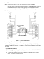
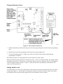
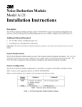
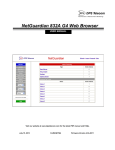
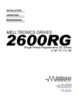
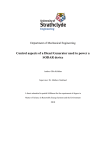
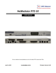
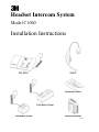
Headset Intercom System
Model C1060
Installation Instructions
Table of Contents
Typical Single Lane Installation......................................................................................................................
Battery Charger ...............................................................................................................................................
Speaker and Microphone Assemblies..............................................................................................................
1
2
3
Standard Systems ......................................................................................................................................
3
Duplex Systems ........................................................................................................................................
3
Base Station .....................................................................................................................................................
Programming Station.......................................................................................................................................
Connecting the Base Station Directly to Components ....................................................................................
3
4
5
Connecting the Base Station to Components Using the Optional Interconnect Module.................................
Connecting the Auxiliary Intercom (Optional) ...............................................................................................
Dual Lane System Installation.........................................................................................................................
Cross Lane System Installation .......................................................................................................................
6
8
9
10
Installation.................................................................................................................................................
11
Wiring the System ..............................................................................................................................
11
Programming the Headsets for Cross-Lane Operation.......................................................................
11
Operation...................................................................................................................................................
12
System Configurations and Function Jumper Settings....................................................................................
Standard Operation – Single Lane System (One Base Station) ................................................................
14
14
Standard Operation – Dual Lane System (Two Base Stations) ................................................................
14
Duplex Operation – Single Lane System (One Base Station)...................................................................
15
Duplex Operation – Dual Lane System (Two Base Stations)...................................................................
15
Channel Selection............................................................................................................................................
Setting Audio Levels .......................................................................................................................................
Duplex Systems Only ...............................................................................................................................
16
17
18
Duplex and Standard Systems ..................................................................................................................
18
Alert Tone Level .......................................................................................................................................
18
Monitor Speaker Volume Levels........................................................................................................
19
Standard Systems Only .............................................................................................................................
19
Listen Level (Menu Sign Microphone Sensitivity) ............................................................................
19
Menu Sign Talk Volume Level ..........................................................................................................
20
i
Table of Contents (continued)
Circuit Board Jumpers, Adjustment Controls, Indicators and Switches .........................................................
Jumpers.....................................................................................................................................................
21
21
Adjustment Controls.................................................................................................................................
22
Indicators ..................................................................................................................................................
22
Switches (etc.) ..........................................................................................................................................
23
Connectors ................................................................................................................................................
23
Finishing Up....................................................................................................................................................
Troubleshooting Audio Feedback ...................................................................................................................
Technical Assistance.......................................................................................................................................
24
24
24
Illustrations
Figure 1. Typical Installation .........................................................................................................................
1
Figure 2. Battery Chargers (3–Slot and 6–Slot Versions)..............................................................................
2
Figure 3. Base Station Mounting Holes .........................................................................................................
3
Figure 4. Programming Station Mounting Holes ...........................................................................................
4
Figure 5. Direct Base Station–to–Component Connections...........................................................................
5
Figure 6. Base Station – Interconnect Module Connections ..........................................................................
6
Figure 7. Connecting Components to the Interconnect Module ....................................................................
7
Figure 8. D–15D (M478 DA) Connections....................................................................................................
8
Figure 9. D–15B and D–15C (M478 BA and CA) Connections....................................................................
8
Figure 10. D–30 Connections ........................................................................................................................
9
Figure 11. Cross–Lane Wiring Diagram ........................................................................................................
11
Figure 12. Removing the Half–Cover from the Base Station ........................................................................
16
Figure 13. Base Station Circuit Board ...........................................................................................................
17
Figure 14. Base Station Circuit Board ...........................................................................................................
21
ii
Typical Single Lane Installation
Figure 1. Typical Installation
Material Required (not supplied)
•
3/4–inch conduit (metal or plastic) – 2 pieces 4–5 feet in length
•
conduit clamps
•
assortment of sheet metal screws
•
two sets of 18–gauge, twisted–pair (two wires each set) audio cable, sufficient in length to connect the
speaker and microphone assembly (in the menu sign) to the interconnect module or base station.
!
Important
The twisted–pair of wires for the microphone connection must be shielded for
proper operation. In duplex systems, microphone and speaker cannot be in the
same jacket unless specially designed for duplex such as 3M 78–8095–0180–8.
•
sufficient twisted–pair sets of audio cable to connect other components such as monitor speaker, vehicle
detection device, etc.
1
Battery Charger
Install the battery charger and begin charging the batteries before you install any other components.
Install the battery charger in a clean, dry environment. An office location is best.
The battery charger may be placed on a flat surface such as a table, desk, etc., or it can be fastened to a wall using
the optional wall–mount kit.
Plug the power supply transformer into a 120–Volt wall outlet and then plug the transformer cord into the
connector in the end of the battery charger. The three green lights on the battery charger will turn on.
To charge a battery, plug it into the charger as shown in Figure 2. Observe the charging status indicator next to
the battery:
•
•
The indicator lights RED to indicate the battery is charging.
The indicator lights GREEN to indicate the battery is fully charged.
9 Note
Discharged batteries require 1–1/2 to 2 hours to charge.
When the battery voltage becomes too low, a short, low volume tone, occurring at seven–second intervals is
heard in the headset. This repeating tone continues for two minutes. After the two–minute interval, the headset
automatically turns off to prevent battery damage.
Figure 2. Battery Chargers (3–Slot and 6–Slot Versions)
2
Speaker and Microphone Assemblies
Standard Systems
For standard systems, install the Deluxe 5–Inch Speaker and Microphone Assembly, Part Number 78–6911–
1545–1. Refer to the installation instructions packaged with the assembly.
Duplex Systems
For duplex systems, install the 3.5–Inch Duplex Microphone (with foam housing), Part Number 78–6911–4476–
6 and the 5–Inch Metal Speaker Assembly, Part Number 78–6911–4411–3. Refer to the installation instructions
packaged with the assemblies.
Base Station
1. For proper system operation, locate the base station module:
•
•
•
5 to 6 feet above the floor
at least 10 feet from the cashier/drive–thru window
At least 3 feet from large metal objects such as refrigerators, ranges, coolers, etc., and other metal or
electrical devices.
!
Important
Do not mount base station under steel countertops, within 3 feet of
coolers/refrigerators/ranges or in areas where it will be obscured by steel
doors, walls, etc. as this will cause operational problems.
2. Mount the base station using the included screws and anchors. (See Figure 3.)
Figure 3. Base Station Mounting Holes
3. Install conduit and cable clamps as necessary.
4. Feed the cables for speaker, microphone, vehicle detect and monitor speaker (if used) through the conduit
down to the interconnect module or base station. (See Figure 1.)
5. Feed the transformer cable from the outlet to the base station. (See Figure 1.)
Keep the transformer cable at least 6 inches from the left half of the base station. This half contains sensitive
radio components which will be affected if the cable is too close.
3
Programming Station
1. For proper system operation, locate the programming station module 18 inches or less from the base station.
An 18 inch cable is provided to connect between the base station and the programming station.
!
Important
Allow enough room below the programming station to allow insertion of the
headset while it is being programmed. Do not mount programming station too
close above the countertop or other wall-mounted object.
2. Mount the programming station module using the included screws and anchors. (See Figure 4.)
Figure 4. Programming Station Mounting Holes
3. Connect the 18 inch long programming cable provided between the base station programming jack and the
programming station jack.
4. If needed, connect the programming cable for use with C860 and C960 headsets and allow it to hang from
the programming station
4
Connecting the Base Station Directly to Components
If an interconnect module is not used, connect the components (vehicle detector, speaker/microphone and
optional monitor speaker) directly to the base station as shown in Figure 5. Use 18–20 gauge twisted pair audio
wire for all connections except the microphone. Use an 18–20 gauge shielded twisted–pair of audio wire for the
connection to the microphone.
!
Important
The twisted–pair of wires for the microphone connection must be shielded for
proper operation. In duplex systems, microphone and speaker cannot be in the
same jacket unless specially designed for duplex such as 3M 78–8095–0180–8.
Figure 5. Direct Base Station–to–Component Connections
5
Connecting the Base Station to Components Using the Optional Interconnect
Module
Connect the base station to the interconnect module as shown in Figure 6. Note that the connections are made to
the “TO CONTROL MODULE” terminals on the interconnect module.
Figure 6. Base Station – Interconnect Module Connections
Connect the components (vehicle detector, speaker/microphone, and optional monitor speaker) to the
interconnect module as shown in Figure 7. Note that the connections are made to the “TO OUTSIDE” terminals
on the interconnect module.
*Note
If an optional back–up (auxiliary) intercom is connected to the “TO AUXILIARY INTERCOM”
on the interconnect module, the base station must be turned off to enable operation/usage of the
back–up intercom.
Use 18–20 gauge twisted–pair audio wire for all connections except the microphone. Use an 18–20 gauge
shielded twisted–pair audio wire for the connection to the microphone.
6
2 EA. 1500 OHM Resistors
Supplied with Duplex Mic
Figure 7. Connecting Components to the Interconnect Module
7
Connecting the Auxiliary Intercom (Optional)
*Note
The base station must be turned off to enable operation/use of the auxiliary intercom.
1. Connect the auxiliary intercom to the “TO AUXILIARY INTERCOM” terminals on the interconnect module
as shown in Figure 8 through Figure 10 (depending on the model of intercom used).
The presence alert shown is wired to operate only when the Model C1060 is turned off.
If a separate outside microphone is used, the auxiliary intercom must be configured for OUTSIDE MIC.
Refer to the Auxiliary Intercom Installation Instructions for information about moving any internal jumpers.
Figure 8. D–15D (M478 DA) Connections
Figure 9. D–15B and D–15C (M478 BA and CA) Connections
8
!
Important
If you use a D–30 as the auxiliary intercom, a separate monitor speaker must
be provided for the Model C1060. (Both the Model C1060 and D–30
intercoms require separate monitor speakers.)
Figure 10. D–30 Connections
Dual Lane System Installation
A dual lane system consists of two separate single lane systems that operate independently of each other. Each
single lane system has its own dedicated base station and headset(s).
To install a dual lane system:
1. Install two single lane systems as outlined in these installation instructions.
!
Important
Base station models C921 and earlier must be mounted at least 25 feet apart.
Base station models C922 may be mounted as close as 2 feet apart.
2. With the base stations turned off, set jumper J3 on one of the base stations so that it jumpers pins 1 and 2.
This designates the base station as a lane 1 system.
3. Set jumper J3 on the other base station so that it jumpers pins 2 and 3. This designates the base station as a
lane 2 system.
!
Important
Do not set both base stations to the same lane number as this will cause
operational problems.
4. Turn on both base stations and press the RESET SWITCH on each of the base station circuit boards to “read”
the jumper setting into the microprocessor.
9
5. Select a channel for each of the base stations. (See page 15 for the channel selection procedure.) After you
select the channel, press the RESET SWITCH on the base station circuit boards to “read” the selection into
the microprocessor.
6. Re–program the headsets as instructed on page 16.
7. Check the operation of each of the systems. Note that the alert tone for the Lane 1 system headsets is a
single repeating “beep” while the alert tone for the Lane 2 system headsets is a double repeating “beep.”
Cross-Lane System Installation
The Cross-Lane system provides communication for facilities that have two menu signs. It consists of two base
stations that are connected to a Cross-Lane Module. A Cross-Lane Module is a five-pole switch that allows the
two systems to be separated during hours of peak activity. Refer to the installation instructions (Document
Number 78-6912-0487) included with the Cross Lane Module (P/N78-6911-4396-6). These instructions are also
located in the Wireless Intercom Service Manual.
A Cross-Lane Module can be useful if the manager wishes to operate each lane with a separate crew during
periods of peak activity. This is accomplished by turning the Cross-Lane switch OFF. By pressing the T1
button on any headset, the operator can communicate with a customer at menu sign 1. By pressing the T2 button
on any headset, another operator can communicate with a customer at menu sign 2. When the Cross-Lane
Module is OFF, the operator will only hear the vehicle detector alert from the menu sign with which he or she
last talked.
During periods of lower activity, the Cross-Lane Module is turned ON, allowing one headset order-taker to
operate both lanes. When the cross-lane module is turned ON, the operator will always hear vehicle detector
alerts from both menu signs. A single alert indicates a vehicle is at menu sign 1 while a double alert indicates a
vehicle is at menu sign 2.
10
Installation
Notes: Both base stations must be set to the same channel number and different lane numbers.
Base station models C921 and earlier must be mounted at least 25 feet apart. Base station models C922
may be mounted as close as 2 feet apart. Test the system prior to installation by placing the base
stations in the desired locations. Set Jumpers and program the headsets. Insure that the talk L.E.D. on
the proper base station lights when the appropriate (T1 and T2) button on the headset is pressed.
Wiring the System
Figure 11. Cross-Lane Wiring Diagram
Programming the Headsets for Cross-Lane Operation
Follow the steps below to program the headsets for Cross-Lane operation, and disable the Talk-Lock function.
It does not matter which base station is used to program the headsets. By pressing T1, the headset will always
communicate with the lane 1 base station; by pressing T2, the headset will always communicate with the lane 2
base station.
1. Disable the Talk Lock function
Talk-Lock is a toggle function that must be checked first to see if it is enabled or disabled. If the Talk LED
lights when the L button is pressed, Talk-Lock is enabled.
•
To disable Talk-Lock, turn the headset OFF, press and hold the L button while pressing ON for 5
seconds. You will hear an acknowledging beep.
11
•
Recheck the Talk-Lock function by pressing the L button. The Talk LED on the base station should not
light.
2. Program the Headsets for Cross-Lane Operation
•
With the headset OFF, press and hold T1 and T2 while pressing ON for 5 seconds. You will hear an
acknowledging beep.
•
Verify that the headsets are properly programmed for Cross-Lane operation:
•
-
Press T1 and verify that the Talk LED lights on the lane 1 base station and does not light on the
lane 2 base station.
-
Press T2 and verify that the Talk LED lights on the lane 2 base station and does not light on the
lane 1 base station.
To remove the Cross-Lane function and return the headsets to the normal operating mode, first turn the
headset OFF, and then hold down T1 while pressing ON for 5 seconds. You will hear an
acknowledging beep.
Operation
Cross-Lane Module OFF
Vehicle detector alerts
The operator will only hear the vehicle detector alert from the menu sign with which he or she last
talked. Vehicles at menu sign 1 will be heard as a single repeating alert. Vehicles at menu sign 2 will
be heard as a double repeating alert.
Answering customers
Pressing T1 will only allow communication with the lane 1 customer. Pressing T2 will only allow
communication with the lane 2 customer.
Paging function
Pressing T1 will only allow communication with other headsets, which recently pressed T1. Pressing
T2 will only allow communication with other headsets, which recently pressed T2.
Cross-Lane Module ON
Vehicle detector alerts
The operator will always hear both vehicle detector alerts. Vehicles at menu sign 1 will be heard as a
single repeating alert. Vehicles at menu sign 2 will be heard as a double repeating alert.
Answering customers
Pressing T1 will only allow communication with the lane 1 customer. Pressing T2 will only allow
communication with the lane 2 customer.
Paging function
Pressing T1 will only allow communication with other headsets, which recently pressed T1. Pressing
T2 will only allow communication with other headsets, which recently pressed T2.
12
Notes:
1. Both vehicle alert tones will be heard at all times with the Cross-Lane Module ON
The order-taker may object to hearing the vehicle alert from the other lane while taking an order; if so, we
suggest you decrease ALERT TONE LEVEL on each base station so it is audible in the headsets but not
objectionable. The tone should be low enough so that the order-taker can ignore it, yet know that someone is
waiting at the other lane.
2. Listening and Paging in a Cross Lane system
With the AUDIO IN and AUDIO OUT wires disconnected, the T1 and T2 buttons control which menu sign
to talk or listen to. They also control which headsets to PAGE to. Disconnecting the AUDIO IN and
AUDIO OUT wires presents some issues if a cook or cashier needs to monitor both lanes:
•
If the cook or cashier is using a headset to monitor lane 1, and the order-taker is taking an order from
menu lane 2, or if the order-taker needs to PAGE the cashier, he/she must first press T1 momentarily,
then press PAGE to communicate privately with the cashier on lane 1. Then the order-taker can press T2
to resume taking the order on lane 2.
•
As an alternative, a monitor speaker from each base station may be installed in the kitchen. (Caution:
Monitor speakers are generally not recommended for duplex systems using C921AA base stations. The
speaker location and volume are usually too critical to avoid feedback. C921BA and C922 base stations
can usually be configured successfully to allow operation of monitor speakers.)
3. The vehicle alerts may echo in the headsets
With the Cross-Lane module turned ON, two rapid single tones may be heard from the lane 1 base station.
To eliminate this problem, turn down the volume of the ALERT TONE LEVEL control, on one of the base
stations.
13
System Configurations and Function Jumper Settings
!
Important
Whenever a jumper setting is changed, the RESET SWITCH on the base station circuit board must be pressed
to program the new jumper setting into the microprocessor. Also, each of the headsets in the system must be
reprogrammed when a jumper setting is changed (see Channel Selection on page 13 for the headset
programming procedure).
Determine the system type (standard operation – single lane, etc.) and identify the type of speaker (speaker only
or speaker and microphone) and the type of vehicle detector (air switch or loop/SODAR detector).
Refer to the base station circuit board illustration (Figure 14) and the applicable system configuration below. Set
the function jumpers as noted and per the type of speaker and vehicle detector in the system. (An illustration of
the circuit board also appears on the decal inside of the base station half–cover.)
Standard Operation – Single Lane System (One Base Station)
Function
Menu Sign with Speaker only (OSM)
Jumper Settings
Jumper pins 1 and 2 on jumpers J1 and J2.
or
Menu Sign with Separate Speaker and
Microphone
Lane 1 System
or
Jumper pins 2 and 3 on jumpers J1 and J2.
Air Switch (Pulse) Detector
Jumper pins 1 and 2 of jumper J4.
or
Loop/Sodar (Presence) Detector
Standard Operation
Menu Power Selection
Talk Monitor Level
or
Jumper pins 2 and 3 of jumper J4.
Jumper pins 2 and 3 of jumper J5.
Jumper must cover the top 2 pins of jumper J6.
Jumper left 2 pins of jumper J9.
Jumper pins 1 and 2 of jumper J3.
Standard Operation – Dual Lane System (Two Base Stations)
Function
Menu Sign with Speaker only (OSM)
Jumper Settings
Jumper pins 1 and 2 on jumpers J1 and J2.
or
Menu Sign with Separate Speaker and
Microphone
Lane 1 System
or
Jumper pins 2 and 3 on jumpers J1 and J2.
Lane 2 System
Air Switch (Pulse) Detector
Jumper pins 2 and 3 on base station 2, jumper J3.
Jumper pins 1 and 2 of jumper J4.
or
Loop/Sodar (Presence) Detector
Standard Operation
Menu Power Selection
or
Jumper pins 2 and 3 of jumper J4.
Jumper pins 2 and 3 of jumper J5.
Jumper must cover the top 2 pins of jumper J6.
Talk Monitor Level
Jumper left 2 pins of jumper J9.
Jumper pins 1 and 2 on base station 1, jumper J3.
14
Duplex Operation – Single Lane System (One Base Station)
Function
Menu Sign with Separate Speaker and
Microphone
Jumper Settings
Jumper pins 2 and 3 on jumpers J1 and J2.
Lane 1 System
Air Switch (Pulse) Detector
Jumper pins 1 and 2 of jumper J3.
Jumper pins 1 and 2 of jumper J4.
or
Loop/Sodar (Presence) Detector
Duplex Operation
Menu Power Selection
or
Jumper pins 2 and 3 of jumper J4.
Jumper pins 1 and 2 of jumper J5.
Jumper bottom 2 pins of jumper J6.
Talk Monitor Level
Jumper left 2 pins of jumper J9.
or
If customer desires, jumper right 2 pins of
jumper J9.
Jumper CRFT 2 pins when using a C1060
headset in Talk Lock mode.
Jumper right 2 pins for all configurations
except those mentioned in “High.”
SWT Threshold (High)
SWT Threshold (NRML)
Duplex Operation – Dual Lane System (Two Base Stations)
Function
Menu Sign with Separate Speaker and
Microphone
Jumper Settings
Jumper pins 2 and 3 on jumpers J1 and J2.
Lane 1 System
Jumper pins 1 and 2 on base station 1,
jumper J3.
Lane 2 System
Jumper pins 2 and 3 on base station 2,
jumper J3.
Air Switch (Pulse) Detector
Jumper pins 1 and 2 of jumper J4.
or
Loop/Sodar (Presence) Detector
Duplex Operation
Menu Power Selection
or
Jumper pins 2 and 3 of jumper J4.
Jumper pins 1 and 2 of jumper J5.
Jumper bottom 2 pins of jumper J6.
Talk Monitor Level
Jumper left 2 pins of jumper J9.
or
If customer desires, jumper right 2 pins of
jumper P9.
15
Channel Selection
The Model C1060 Headset Intercom System can operate on any one of eight different channels.*
Select a channel that neither receives or causes interference and then program the headsets to that channel using
the following procedure:
1. Pull slightly outward on the lower right side of the base station half–cover and then lift and remove the cover
as shown in Figure 12.
Figure 12. Removing the Half–Cover from the Base Station
2. With the base station turned on, press and release the CHANNEL SELECT switch once. (This advances the
system to the next channel.) One of the red indicators (1–8) will light, indicating the newly selected channel.
!
Important
After making any changes to the base station jumper settings, you must press
the RESET SWITCH to “read” the new settings into the microprocessor.
!
Important
When two systems are used in a dual lane application, each base station must
be set to the same channel, and one base station must be set to Lane 1 and the
other to Lane 2.
*Note
If you are installing this as a single lane system, 8 channels on the LANE 2 setting are also
available for use.
16
Channel Selection (Cont.)
Figure 13. Base Station Circuit Board
3. With the headset/belt pack turned off, plug one end of the programming cable into the headset programming
jack.
4. Plug the other end of the programming cable into the base station modular jack.
5. Turn on the headset/belt pack. (Audible tones will be heard in the headset earpiece indicating that
programming is complete.)
The headset/belt pack is now programmed to the same channel as the base station.
Repeat the channel selection procedure if interference occurs. After seven channel changes, the original channel
will again be encountered. If interference is still present and the system is a single lane system, try changing the
J3 lane designation jumper from lane 1 to lane 2. If this fails and none of the channels are interference free,
contact your 3M representative.
Setting Audio Levels
To set the audio levels, refer to the related audio level procedure below and to the illustration of the base station
circuit board (Figure 14). All the audio level adjustment controls are located on the base station circuit board.
(An illustration of the circuit board also appears on the decal mounted to the base station.)
17
Duplex Systems Only
The following procedure sets system audio levels for duplex systems so that headset/belt pack volume controls
have enough “range” to allow operators to adjust headset volume to their preference.
*Note
The microphone at the menu sign must be located within four feet of the vehicle for duplex
operation.
To set the audio levels:
1. Turn the base station MENU MIC SENS control to minimum (CCW).
2. Adjust the headset volume control to maximum.
3. Press the headset Talk switch, and set the base station outbound (DAY/NIGHT) audio levels to the desired
level at the post/sign.
4. Press and hold the headset/belt pack Talk switch, and turn the base station MENU MIC SENS control up
(CW) until feedback occurs. Then turn the MENU MIC SENS level control down (CCW) until the feedback
stops.
5. Check each additional headset/belt pack (to be used in the system) at maximum volume. Verify that feedback
does not occur. If feedback occurs, adjust the MENU MIC SENS level down until the feedback stops.
6. Lower the volume control on the headset/belt pack 2 levels from maximum, and check that the inbound
audio level from the menu mic is usable. If everything is all right, the audio will be too loud.
7. Compare this inbound listen level in the headset to the page audio level from another headset.
8. Adjust the MENU MIC SENS level down (never up) to match the page audio level as required.
9. If the inbound listen level cannot be made to match the page audio level, then more acoustic isolation is
needed for the menu mic and menu speaker.
This procedure ensures that feedback will not occur even if the headset/belt pack is run at its maximum setting. It
is also a measure of how the menu sign/post components are placed in relation to one another.
Duplex and Standard Systems
*Note
For Duplex systems, the microphone at the menu sign must be located within four feet of the
vehicle for duplex operation.
For Standard (half–duplex) systems, jumper J6 must be placed in the STD position.
The following procedures apply to both duplex and standard systems.
Alert Tone Level
The alert tone level is the volume of the alert tone heard in the headset.
To set the alert tone level:
1. Turn the headset off and then on. (This sets the volume control to midrange.)
2. Have someone drive a vehicle up to the menu sign. When the vehicle is detected, you will hear the vehicle
alert tone in the headset.
18
3. Adjust the HEADSET ALERT LEVEL control to provide a comfortable alert tone level in the headset
(clockwise to increase; counterclockwise to decrease).
Monitor Speaker Volume Levels
The monitor speaker volume levels are the levels for the various functions heard through the optional monitor
speaker. All adjustment controls are located on the base station circuit board. Turn the controls clockwise to
increase the volume and counterclockwise to decrease volume.
To set the monitor speaker volume levels:
1. Set the master MON VOLUME control to the midrange position.
2. With a vehicle detected at the menu sign (alert tone sounding), adjust the MON ALERT control so that the
alert signal coming through the monitor speaker is at a suitable level.
3. Press and hold the headset Talk switch and speak into the headset microphone. Adjust the MON TALK
control so that the talk audio coming through the monitor speaker is at a suitable level.
4. Press the headset Page switch and speak into the headset microphone. Adjust the MON PAGE control so
that the page audio coming through the monitor speaker is at a suitable level.
5. While you listen to audio coming from the menu sign, adjust the MON IN control so that the menu sign
audio coming through the monitor speaker is at a suitable level.
*Note
If any monitor functions are not desired by the customer, turn the related adjustment control fully
counterclockwise to silence the function.
Standard Systems Only
The following procedures apply only to standard systems.
*Note
For Standard (half–duplex) systems jumper J6 must be placed in the STD position.
Listen Level (Menu Sign Microphone Sensitivity)
The listen level is the volume of the menu sign audio heard in the headset.
To set the listen level:
1. Turn the headset/belt pack off and then on. (This sets the volume control to midrange.)
2. Have someone drive a vehicle up to the menu sign. When the vehicle is detected, you will hear the vehicle
alert tone in the headset/belt pack.
3. Press and release the headset Talk switch to cancel the alert tone and allow you to listen to the audio from the
menu sign.
4. Adjust the MENU MIC SENS level control for the desired volume (clockwise to increase volume;
counterclockwise to decrease.)
The Listen Level should now be properly adjusted. Because the headset/belt pack volume control was set at
midrange, there will now be enough range (up/down) in the headset/belt pack volume control to allow operators
to set the headset volume to a preferred level.
19
Menu Sign Talk Volume Level
The menu sign talk volume level is the volume of the headset/belt pack audio heard at the menu sign.
To set the menu sign talk volume level:
1. Move the DAY/NIGHT switch on the base station to the DAY position.
2. Press and hold the headset/belt pack Talk switch and speak into the headset microphone.
3. Adjust the DAY menu sign audio level control for the desired audio level at the menu sign (clockwise to
increase; counterclockwise to decrease.)
4. Move the DAY/NIGHT switch on the base station to the NIGHT position.
5. Press and hold the headset Talk switch and speak into the headset microphone.
6. Adjust the NIGHT menu sign audio level control so that the audio level at the menu sign is slightly lower
than the DAY audio level setting (clockwise to increase; counterclockwise to decrease.)
20
Circuit Board Jumpers, Adjustment Controls, Indicators and Switches
Figure 14. Base Station Circuit Board
Jumpers
J1 and J2
Set for the type of menu sign in the system. Jumper pins 1 and 2 on both jumpers for menu
signs having a speaker only. Jumper pins 2 and 3 on both jumpers for menu signs having a
speaker and a microphone.
J3
Set to designate the number of the lane in the system. Jumper pins 1 and 2 to select lane 1.
Jumper pins 2 and 3 to select lane 2.
J4
Set for the type of vehicle detector in the system. Jumper pins 1 and 2 for an air switch
detector. Jumper pins 2 and 3 for a loop/sodar detector.
J5
Set to designate the type of communication operation. Jumper pins 2 and 3 for standard
operation. Jumper pins 1 and 2 for duplex operation.
J6
MENU PWR SEL – STD or DPLX
STD – applies power to outbound speaker amplifiers only when the TALK switch is pressed.
Note: for Standard (half–duplex) operation J6 MUST be placed in the STD position.
DPLX – applies power to outbound speaker amplifiers constantly. This will reduce the click
that is sometimes heard in duplex mode when the TALK button is pressed.
J9
TALK MON LVL
REDUCE – reduces the volume to the Monitor Speaker by 16dB while TALK is activated.
This decreases the chance of feedback when a headset is operating near the Monitor Speaker in
duplex mode.
FULL – unreduced volume to monitor speaker in all modes.
*Note
This setting may cause feedback when a headset is operating near the monitor
speaker in duplex mode.
J10
SWT THLD – HIGH or NRML
SWT THLD refers to Switch Threshold. This jumper is used to change the dynamic gain
21
threshold circuitry of the menu microphone. It should normally be set to NRML.
Occasionally, the inbound audio volume will decrease when C1060 headsets are used in Talk
Lock mode. Set jumper J10 to HIGH, in this case only.
HIGH – Jumper the left two pins ONLY if a decrease in inbound volume is noticed while
C1060 headsets are being used in Talk Lock mode.
NRML – The Normal setting is used for all configurations except those mentioned in “HIGH.”
!
Important
After changing any jumper setting(s), be sure to press the RESET SWITCH on
the base station circuit board to “read” the change into the microprocessor.
Adjustment Controls
MENU MIC SENS
Controls the volume of the menu sign audio heard in the headset.
HEADSET ALERT LEVEL
Controls the volume of the alert tone heard in the headset.
DAY
Controls the volume heard at the menu sign with the Day/Night switch in
the Day position.
NIGHT
Controls the volume heard at the menu sign with the Day/Night switch in
the Night position.
MON VOLUME
Master volume control for the following functions heard through the
optional monitor speaker:
MON ALERT
MON IN
MON PAGE
MON TALK
Controls the alert tone level.
Controls the audio level coming from the menu sign.
Controls the page audio level coming from the headset/belt pack
microphone.
Controls the talk audio level coming from the headset/belt pack
microphone.
*Note
If any of the monitor functions are not desired by the customer, turn the appropriate adjustment
control completely counterclockwise to silence that particular function.
Indicators
POWER
CHANNEL 1–8
LOOP FAILURE
DETECTOR POWER
NRM
VEHICLE
TALK
PAGE
Lights when power is applied to the base station.
Lit LED indicates which channel is selected for base station operation.
(Optional) Flashes if vehicle loop fails.
(Optional) Lights if optional Loop Detector is functioning.
(Optional) Flashes slowly if optional noise reduction module is functioning.
Lights when a vehicle is detected at the menu sign.
Lights during communication between headset/belt pack and menu sign.
Lights during paging from headset/belt pack.
22
Switches (etc.)
ON/OFF Switch
DAY/NIGHT VOLUME Switch
NRM ON/OFF
CHANNEL SELECT Switch
Programming Jack
RESET Switch
Controls power to the base station.
Selects volume for day or night operation.
(Optional) Press to turn noise reduction module ON. Press to turn noise
reduction module OFF.
Selects base station operating channel.
For programming headsets/belt packs to the same channel as the base station.
For programming new channel selection or jumper setting(s) into the
microprocessor.
Connectors:
C5000 Terminal Strip
J7
J8
An extra 4 terminals at the bottom of the right–hand terminal block.
Loop Detector Connector
Noise Reduction Connector (under left half–cover)
23
Finishing Up
1. Secure any loose wires.
2. Replace the cover on the base station module.
3. Check the operation of the system.
4. Check the operation of the auxiliary intercom.
5. Perform operator training, including the following functions:
•
Normal use and care of the system.
•
Use and care of the headset.
•
Battery replacement and recharging.
•
Operation of the base station module switches and controls.
•
Operation of optional Noise Reduction Module
•
Operation of Loop Detector
Refer to the Model C1060 Headset Intercom System Operating Instructions.
Troubleshooting Audio Feedback
If audio feedback occurs, check the following and correct as necessary:
•
Is the microphone audio cable shielded twisted pair – grounded at the inside end?
•
Is the microphone audio wiring separately contained in its own cable, with no other “active” wires in the
same cable?
•
Are the speaker and microphone at least 14 inches apart?
•
Is the outbound audio level too high?
•
Is speaker audio being reflected back to the microphone from nearby surfaces?
Technical Assistance
For technical assistance, call 1–800–328–0033 or write to 3M Food Service Business at the following address:
3M Commercial Care Division
Food Service Business
3M Center
St. Paul, MN 55144–1000
24
3
Commercial Care Division
Food Services Business
3M Center
St. Paul, MN 55144-1000
Printed in U.S.A.
©3M 2003 October
70-0710-3649-8 Rev. D