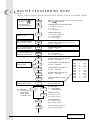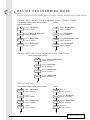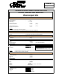
1
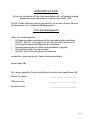
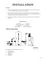
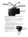
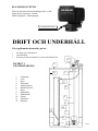
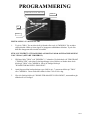
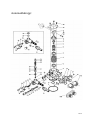
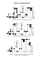
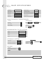
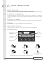
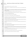
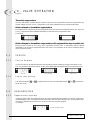
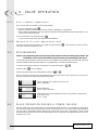
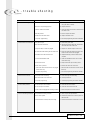
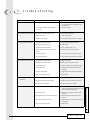
INSTRUKTION
Maxi-humus
Mårdvägen 7, 352 45 Växjö, 0470 – 700 600, E-mail: [email protected]
Upplaga 06-1
Sid 1
GARANTIVILLKOR
Ni har just installerat ett filter från Aqua Expert AB, ett ledande företag i
branschen med erfarenhet av vattenrening sedan 1970.
För att ni skall känna Er extra trygg med Ert val av Aqua Expert AB som
filterleverantör, ger vi följande återköpsgaranti.
2 års återköpsgaranti
Villkor för återköpsgaranti:
*
Att Socialstyrelsens allmänna råd för enskilda dricksvattentäkter
SOSFS 2003:17 inte uppfylls av filtret för det filtret är avsett för.
*
Att komplett offererad anläggning är installerad.
*
Att pumpkapaciteten för filtrets spolvattenbehov uppfylls.
*
Att råvattenkvalitén inte har ändrats.
*
Att filtret har skötts enligt givna instruktioner.
Installation, demontering och frakter kostnadsersätts ej.
Aqua Expert AB
Fyll i dessa uppgifter för att underlätta vid kontakt med Aqua Expert AB.
Datum för inköp:
_______________________
Offertnummer:
_______________________
Analysnummer:
_______________________
Sid 2
INSTALLATION
VIKTIGT!
*
För att få en fullgod funktion av filtret måste inkommande vattentryck ligga på minst
1,5 bar vid backspolning och max 6,0 bar vid filtrering.
*
Placera ej filtret för nära en varmvattenberedare (minst 3 meter rör mellan utgående
ledning på filtret och inkommande på varmvattenberedaren). Varmvattenberedaren kan i
vissa fall överföra värme via kallvattenröret till filtret.
*
För att öka livslängden av automatiken bör ett patronfilter monteras före humusfiltret
(tillbehör).
TEKNISK DATA
Arbetstryck…………..1,5-6,0 bar
Max arbetstemperatur…...40 grader C
Elanslutning…...…230 V 50 Hz
Röranslutning………...R25 Invändig gänga
Filtrets placering:
2.
4.
3.
1.
5.
Principskiss
Filtret kopplas efter hydroforen/hydropressen.
1.
2.
3.
4.
5.
Råvattenpump
Tryckströmbrytare
Hydrofor
Humusfilter
Patronfilter
Sid 3
UT
IN
BY-PASSVENTIL
AVLOPPSANSLUTNING
TIMERHUVUD
1.
Inkommande och utgående vatten: Koppla inkommande och utgående ledning till
”IN” respektive ”UT” på automatiken. När du står framför automatiken är
inkommande till höger och utgående till vänster.
2.
Avloppsanslutning: Koppla en slang (minst 1/2 ”) till ”AVLOPPSANSLUTNING”
på automatikens högra sida. Se till att slangen sitter fast ordentligt t.ex. med en
slangklämma. Placera sedan slangen i en golvbrunn, spilltratt eller liknande.
Försäkra er om följande:
*
att slangen är så kort som möjligt. Om slangen behöver vara mer än 5 meter
använd 3/4”
*
att slangen ej stiger uppåt någonstans.
*
att slangen ej är igensatt av smuts eller dylikt.
Uppfylls ej dessa punkter kan det skapas ett oönskat tryckfall som påverkar resultatet
av backspolningen. Anslut även en avloppsslang från kabinetten / salttanken till
avlopp. OBS! Koppla ej ihop denna slang med slangen från automatiken, det kan då
tryckas in spolvatten i kabinetten / salttanken.
3.
Doseringsslang: Salttanken anslutes med
doseringsslangen ifrån flottören i salttanken till
”ANSLUTNING FÖR DOSERINGSSLANG”
på automatiken. Det är snabbkoppling i
salttanken, tryck in och dra ut för att känna att det
har fastnat. Koppla enligt ritningen till höger för
anslutningen vid automatiken.
4.
ANSLUTNING FÖR
DOSERINGSSLANG
Elanslutning: Elanslutning göres med 220 volts
jordat eluttag.
Sid 4
IGÅNGSÄTTNING
KNAPP FÖR MANUELL SPOLNING
Cykel
Funktion
Svensk benämning
Service
Service
Service / Driftläge
1
Backwash
Backspolning
2
Brine + Rince
Uppsugning /
långsamsköljning
3
Rapid Rinse
Snabbsköljning
4
Brine Refill
Återfyllning
Automatik framifrån
När installationen är klar är filtret färdigt för att sättas i drift.
Gör enligt följande samtidigt som du letar efter eventuella läckage:
1.
Sätt filtret i by-pass och släpp på inkommande vatten. Öppna ett tappställe i närheten
efter filtret och låt vattnet rinna i ca 2 minuter. Detta för att eventuell smuts och
avlagringar som bildats vid installationen skall spolas bort. Stäng sedan tappstället.
2.
Öppna sakta by-passen till service / driftläge och låt vattnet fylla filtertanken.
3.
Anslut strömmen.
4.
Tryck in ”KNAPP FÖR MANUELL SPOLNING” och håll knappen intryckt i ca 5
sekunder tills automatiken går igång och det blinkar en 1:a i displayen. Låt filtret spola
tills det automatiskt hoppar över till nästa cykel(6 minuter), fyll dock på ca 15 liter
vatten i kabinetten/salttanken. Återstående tid innan cyklerna är färdig syns i
displayen. Första siffran visar vilken cykel, andra siffran visar återstående tid.
5.
När automatiken stannat i cykel 2, låt filtret suga upp vatten tills nivån ej sjunker mera,
ca 3-5 cm kvar i kabinetten.
6.
Tryck in ”KNAPP FÖR MANUELL SPOLNING”, automatiken går till cykel 3,
hoppa över denna cykel genom att trycka in ”KNAPP FÖR MANUELL
SPOLNING” när siffran 3 slutat blinka.
7.
Tryck in ”KNAPP FÖR MANUELL SPOLNING” och låt automatiken gå hela cykel
4 och sen till serviceläge. Nu blir det automatiskt rätt mängd vatten i kabinetten.
8.
Fyll på salt. Ca 50 kg går att fylla på.
INGÅR EJ I LEVERANSEN.
Sid 5
BLANDNINGSVENTIL
Filtret är utrustat med en blandningsventil, se bild,
denna skall vara dragen i botten.
OBS! felgängad = vänstergängad.
BLANDNINGSVENTIL
DRIFT OCH UNDERHÅLL
Gör regelbundna kontroller på att:
*
*
*
det finns salt i kabinetten.
salt förbrukas.
klockan på timern stämmer överens med aktuell tid.
1.
FILTRET I
GENOMSKÄRNING
2.
12.
1.
2.
3.
4.
5.
6.
7.
8.
9.
10.
11.
12.
Automatik
Lock
Dysa
Filtertank
Jonbytarmassa
Distributionsrör
Dysa
Saltlösning
Saltbriketter
Flottör
Flottörhus
Kabinett
3.
11.
4.
5.
6.
10.
10.
7.
9.
8.
Sid 6
PROGRAMMERING
KNAPP FÖR MANUELL SPOLNING
DISPLAY
ÖKA
MINSKA
INSTÄLLNING AV AKTUELL TID
1.
Tryck in ”ÖKA” för att tiden skall gå framåt eller tryck in ”MINSKA” för att tiden
skall gå bakåt. Håller ni inne någon av knapparna snabbräknar klockan. Tryck eller
håll inne knapparna tills rätt tid är inställd.
STÄLL IN FILTRET ATT BACKSPOLA KLOCKAN 02:00 OCH BACKSPOLNING
VAR 7:E DAG (OFTARE VID BEHOV).
1.
Håll inne både ”ÖKA” och ”MINSKA” i 5 sekunder. En diod tänds vid ”PROGRAM”
i ”DISPLAYEN” och tiden för backspolningen visas. Behöver ni ändra detta värde
klicka på ”ÖKA” eller ”MINSKA. När ni är färdiga klicka på
”KNAPP FÖR MANUELL SPOLNING”.
2.
Antal dagar mellan backspolningar syns. Ställ in på –7 genom att klicka på ”ÖKA”
eller ”MINSKA. Detta värde kan ställas in från 1 till var 99:e dag.
3.
När ni är färdiga klicka på ”KNAPP FÖR MANUELL SPOLNING”, automatiken går
tillbaka till serviceläget.
Sid 7
EXTRA BACKSPOLNING
Det finns två sätt att backspola manuellt. Antingen om man vill göra en
backspolning omedelbart eller om en backspolning skall ske kommande natt på den tid som
är inställd för backspolning.
Omedelbar backspolning:
Tryck in ”KNAPP FÖR MANUELL SPOLNING” och håll den intryckt 5 sekunder. En
backspolning startar. För att påskynda cyklerna kan man trycka in ”KNAPP FÖR
MANUELL SPOLNING” så går den vidare till nästa cykel.
Backspolning kommande natt:
Tryck in ”KNAPP FÖR MANUELL SPOLNING” och släpp den omedelbart, dioden vid
service börjar blinka. Detta innebär att filtret kommer att backspola kommande natt på
inställd tid.
ÖVRIGT:
För att säkra en korrekt funktion av filtret skall följande punkter utföras med jämna
mellanrum, ca 2 ggr om året:
1.
2.
3.
4.
5.
6.
Rengör injektorn.
Rengör återfyllningsregulatorn.
Rengör backspolningsregulatorn.
Kontrollera programmering och tid.
Kontrollera de olika cyklernas funktion.
Kontrollera inkommande och utgående tryck och justera dessa vid behov.
Sid 8
Automatikkropp:
Sid 9
Nummer:
Detaljnummer:
Beskrivning:
1
13255
Adapterclips
2
13242
Packning
3
61400-12
Automatikkropp
4
13304
O-ring (distributionsrör)
5
12281
O-ring (tank)
7
14241
Distans
8
13247
Kolv
9
10696
Kolvsprint
10
13001
Kolvstång
11
12953
Låsmutter (kolv)
12
13446
Ändplugg
14
13315
Skruv (lock injektorhus)
15
19228
Adapter
16
13305
O-ring (adapter)
17
13314
Skruv (adapter)
18
12638
O-ring (avlopp)
19
13301
O-ring (injektor)
20
13302
O-ring (vätskeventilsdistans)
21
13303
O-ring (lock injektorhus)
22
13163
Injektorkropp
23
10913U
Injektormunstycke
24
10914
Injektorhals
25
10227
Injektorfilter
26
13166
Lock (injektorhus)
27
13172
Skaft (vätskeventil)
28
12626
Säte (vätskeventil)
29
13165
Huv (vätskeventil)
30
13167
Distans (vätskeventil)
31
12550
Packning
32
11973
Fjäder (vätskeventil)
33
16098
Bricka (vätskeventil)
34
11981-01
Låsbricka
35
10329
Anslutningsmutter
36
10330
Kona
37
10332
Stödhylsa
38
12094
Återfyllnadsregulator
39
12977
O-ring (återfyllnadsregulator)
40
13245
Hållare (återfyllnadsregulator)
41
13244
Beslag (återfyllnadsregulator)
42
Backspolningsregulator
43
13173
Hållare (backspolningsregulator)
44
12767
Smutsfilter
45
15348
O-ring (backspolningsregulator)
46
13497
Luftspridare
47
13546
Lås (ändplugg)
48
12112
Skruv
49
13363
Bricka
50
13296
Skruv
51
13398
Anslutningsok
52
13308
Slangnippel
53
13918
Plugg (återfyllnadsregulator)
54
13302
O-ring (plugg återfyllnadsregulator)
55
13857
Plugg (vätskeventil)
Sid 10
UNDERHÅLLSGUIDE
Filtret ger ej rent vatten:
Orsak:
1. Filtret står i by-pass
2. Hög vattenförbrukning
3. Filtret utför en returspolning
4. Förlust av filtermaterial
5. Förändrad humushalt i vattnet
6. Filtret backspolar inte
7. Filtret suger ej saltlösning
8. Dålig utbyteskapacitet på filtermassan
9. Inget salt i kabinetten/salttanken
10. Läcka på filtertank
11. Läcka på distributionsrör
12. För lite vatten i kabinetten/salttanken
Åtgärd:
Stäng by-passen, öppna till filtret
Anpassa spolintervallen till förbrukningen
Vänta till backspolningen är klar
Se problem ”´Förlust av filtermaterial”
Justera backspolningsintervallen
Se problem ”Filtret backspolar ej”
Se problem ”Filtret suger ej saltlösning”
Rengör eller byt filtermassa
Fyll på salt
Försäkra er om att automatiken är korrekt ansluten i
filtertanken och att tanken ej är spräckt
Byt distributionsrör
Se problem ”Filtret återfyller ej kabinetten”
Filtret backspolar ej:
Orsak:
1. Ingen spänning fram till automatiken
2. Backspolningsdagar ej inställda
3. Defekt motor
Åtgärd:
Kontrollera elanslutningar och säkringar
Ställ in dagar för backspolning på tapphjulet
Byt motor
Filtret suger ej salt:
Orsak:
1. För lågt tryck på inkommande ledning vid
backspolning
2. Igensatt injektor och/eller smutsfilter
3. Igensatt avloppsledning
4. Igensatt doseringsledning
5. Läcka på doseringsledningen
6.
7.
8.
Ej tillräckligt med vatten i kabinetten
Igensatt backspolningsregulator
Läcka mellan packningar och distanser
Åtgärd:
Öka trycket, måste vara minst 1,5 bar
Rengör injektor och/eller smutsfilter
Rengör avloppsledningen.
Rengör doseringsledningen
Kontrollera doseringsledningen och dess kopplingar så att de ej
läcker eller suger luft
Se problem ”Filtret återfyller ej”
Rengör backspolningsregulator
Rengör/byt packningar och distanser
Filtret går igenom cyklerna oavbrutet:
Orsak:
1. Defekt timermekanism
Åtgärd:
Byt timermekanism
För mycket vatten i kabinetten:
Orsak:
1. Filtret suger ej salt
2. Felaktigt inställd saltdosering
3. Felaktig eller saknad återfyllningsregulator
4.
Igensatt backspolningsregulator
Åtgärd:
Se problemet ”Filtret suger ej salt”
Justera saltdoseringen
Kontrollera att rätt återfyllningsregulator är monterad och rätt
dimensionerad
Rengör backspolningsregulator
Sid 11
Filtret förbrukar för mycket salt:
Orsak:
1.
För mycket vatten i kabinetten
2.
För täta backspolningsintervaller
3.
Felaktigt inställd saltdosering
Åtgärd:
Se problem ”För mycket vatten i kabinetten”
Justera backspolningsintervallerna på tapphjulet
Justera saltdoseringen
Saltsmak i vattnet efter backspolning:
Orsak:
1.
För mycket vatten i kabinetten
2.
Injektorn är underdimensionerad
3.
Felaktigt inställd saltdosering
4.
Partiklar i injektorhus
Åtgärd:
Se problem ”För mycket vatten i kabinetten”
Kontrollera injektorns dimension och byt om den är felaktig
Justera saltdoseringen
Rengör injektorhus
Förlust av filtermaterial i avloppet:
Orsak:
1.
Felaktig eller saknad backspolningsregulator
2.
3.
Övre/undre dysa skadad
Läcka mellan filtertank och övre dysa
Åtgärd:
Kontrollera att backspolningsregulator är monterad och rätt
dimensionerad
Byt dysa
Kontrollera att automatiken är rätt monterad i filtertanken och
att dysa och filtertank ej är spräckta
Förlust av vattentryck:
Orsak:
1.
Filtertanken är full med föroreningar
2.
Utgående/inkommande ledning igensatt
3.
Igensatt undre och/eller övre dysa
4.
Krossad undre och/eller övre dysa
Åtgärd:
Rengör filtermaterial och automatik, backspola tätare
Rengör utgående/inkommande ledning
Rengör dysorna
Byt ut dysorna
Avloppet rinner hela tiden:
Orsak:
1.
Läcka mellan packningar och distanser
2.
Automatiken har fastnat i läge backspolning
3.
Defekt motor
Åtgärd:
Rengör/byt packningar och distanser
Rengör automatik
Byt motor
Filtret återfyller ej kabinetten:
Orsak:
1.
Felaktigt inställd saltdosering
2.
Felaktig återfyllningsregulator
3.
Igensatt återfyllningsregulator
Åtgärd:
Justera saltdoseringen
Kontrollera att återfyllningsregulator är rätt dimensionerad
Rengör återfyllningsregulator
Sid 12
PRINCIPSKISSER
Humusfilter monterat med Göingefilter Kombi.
Humusfilter monterat med Göingefilter K.
Humusfilter monterat med kombinations-/pH-höjande filter
som är placerat efter hydroforen.
Sid 13
Kontakta
AQUA EXPERT AB
vid eventuella frågor.
Sid 14
ELECTRONIC SE
SERVICE MANUAL
1
VALVE SPECIFICATION
P. 2
2
VALVE INSTALLATION
P. 3
3
INSTALLATION INSTRUCTIONS
P. 4
4
VALVE OPERATION
P. 5
5
TROUBLE SHOOTING
P. 7
1 - VALVE SPECIFICATIONS
Installation N°
System capacity
m3°TH
Valve serial N°
Inlet water hardness
°TH
Tank(s) size
Water hardness after mixing valve
°TH
Resin type
Brine tank size
L
Resin volume
Quantity of salt per regeneration
Kg
VALVE TECHNICAL CHARACTERISTIC
INITIATION
REGENERATION SET AT
Time clock
Days
Meter delayed
REGENERATION TIME
Meter immediate
2 o’clock A.M.
/
or
m3 or l
Hour
REGENERATION CYCLES SETTING
Cycle 1
min
Cycle 2
min
Cycle 3
min
Cycle 4
min
HYDRAULIC SETTING
Pressure regulator
Injector size
Drain line flow control (DLFC)
GPM
Brine line flow control (BLFC)
GPM
2,1 bar (30 PSI)
1,4 bar (20 PSI)
Without
VOLTAGE
24V / 50Hz
24V / 60Hz without transformer
NOTES
2
electronic SE
2 - VALVE INSTALLATION
2.1
WATER PRESSURE
A minimum of 1,8 bar of water pressure is required for regeneration valve to operate effectively. Do not exceed 8,5
bar ; if you face this case, you should install a pressure regulator upstream the system.
2.2
ELECTRICAL CONNECTION
An uninterrupted alternating current supply is required. Please make sure your voltage supply is compatible with
your unit before installation. If the electrical cable is damaged, it must imperatively be replaced by a qualified
personal.
2.3
EXISTING PLUMBING
Existing plumbing should be in a good shape and free from lime. The installation of a pre-filter is always advised.
2.4
BY-PASS
Always provide a by-pass valve for the installation, if unit is not equipped with one.
2.5
WATER TEMPERATURE
Water temperature is not to exceed 43°C, and the unit cannot be subjected to freezing conditions.
2.6
PRESENTATION
Service indicator
Flow indicator
Valve in service : dot on
Regeneration tonight : flashing dot
Water flow : Flashing dot
Setting buttons
Program indicator :
Program mode entered : dot on
Regeneration button
Depending on the type of valve, the pictogram order can be different
Backwash
Rapid rinse
Brine draw & slow rinse
Up flow
Brine draw & slow rinse
Down flow
Brine refill
Symbol means cycle not used on
Filter valve
Note: depending on the type of valve, some of these symbols will be used.
3
electronic SE
3 - INSTALLATION INSTRUCTIONS
3.1
Install the unit making sure the tanks are level and on a firm base.
3.2
During cold weather it is recommended that the installer warms the valve up to the room temperature before
operating.
3.3
All plumbing should be done in accordance with local plumbing code. The pipe size for the drain line should be a
minimum of 13 mm (1/2’’). For length exceeding 6 m and backwash flow above 7 gpm, the drain line should be a
minimum of 19 mm (3/4’’).
For the 2850 SE and 9500 SE the pipe size for the drain line should be a minimum of 19 mm.
3.4
Solder joints on the principal plumbing and near the drain must be done prior to connecting the valve. Failure to do
this could cause irreversible damage to the valve.
3.5
Teflon® tape is the only sealant to be used on the drain fitting.
3.6
Make sure that the floor is clean beneath the salt storage tank and that it is level.
3.7
On units with a by-pass, place in by-pass position. Turn on the main water supply. Open a cold soft water tap
nearby and let run a few minutes or until the system is free from foreign material (usually solder) that may have
resulted from the installation. Once clean, close the water tap.
3.8
Place the by-pass in service position and let water flow into the mineral tank. When water flow stops, slowly open
a cold water tap nearby and let run until the air is purged from the unit.
3.9
Plug the valve into an approved power source. Once powered, it is possible that the valve drives itself to the service position.
3.10
Set the time of day (see chapter 4.1.2)
3.11
Fill approximately 25 mm of water above the grid plate (if used). Otherwise, fill to the top of the air check in the brine
tank. Do not add salt to the brine tank at this time.
3.12
Start a manual regeneration (see chapter 4.2.2). Bring the valve in the brine draw and slow rinse position and let it
draw the water contents in the brine tank until it stops. The water level will approximately be in the middle of the
air check cage.
For twin valves (8500, 9000 and 9500) : during this position, the second tank fills up with water. When the flow stops,
open a cold water tap and let run to purge the air inside the tank.
3.13
Now bring the valve in brine refill position and let it get back to service position automatically.
3.14
Now you can add salt to the brine tank, the valve will operate automatically.
4
electronic SE
4 - VALVE OPERATION
Timeclock regeneration
The valve will operate normally until the number of days since last regeneration reaches the regeneration day
override setting. Once this occurs, a regeneration cycle will be initiated at the pre-set regeneration time.
Meter delayed or immediate regeneration
As treated water is used, the volume remaining display will count down from a maximum value to zero. Once this
occurs, a regeneration will be initiated immediately or delayed to the set regeneration time.
For example :
530 litres of treated water remainig
0 litre of treated water remaining
Meter delayed or immediate regeneration with regeneration days override set
When the valve reaches its set of days since regeneration override value, a regeneration will be initiated
immediately or at the pre-set regeneration time. This event occurs regardless of the volume remaining display
having reached zero litre.
4.1
SERVICE
4.1.1
Service displays
In service the time of day will alternatively be viewed with the volume remaining, (except for the timeclock version : only the time of day will be viewed), for twin valves (8500, 9000 and 9500) the tank in service will be shown.
Time of day
4.1.2
Volume remaining
Tank in service
time of day setting
Push either the button
or
to adjust the time of day. Push and hold the button
or
to adjust fas-
ter the time of day.
4.2
REGENERATION
4.2.1
Regeneration displays
During the regeneration, the display will show the current regeneration step number the valve is advancing to
(flashing display) or has reached and the time remaining in that step (fixed display). Once all regeneration steps
have been completed, the valve will return to service and resume normal operation.
For example :
27 minutes remaining in step #2
5
electronic SE
4 - VALVE OPERATION
4.2.2
Start a manual regeneration
There are two options to initiate a manual regeneration :
1- Press and release the button
:
- With an immediate regeneration, the valve will start immediately a regeneration.
- With a delayed regeneration, the service diode will begin to flash immediately and the regeneration occurs
at the preset regeneration time.
2- Press and hold for 5 seconds the button
:
- In any case the valve will go into regeneration immediately.
4.2.3
Advance to the next regeneration cycle
To advance to the next regeneration cycle position, push the button
if the valve is advancing the next cycle.
4.3
. This action won’t have any effect
PROGRAMMING
Caution : the programming has to be done only by the installer for the valve setting of parameters. The
modification of one of these parameters could prevent the good functioning of the device.
To enter the program mode the valve has to be in service. While in the program mode, the valve will continue to
operate normally monitoring all information. The programming is stored in permanent memory.
To enter in the program mode, push and hold for 5 seconds both buttons
Push the button
.
once per display.
Change the option setting by pushing either the buttons
or
.
Note: You must pass through all the programming steps and come back in service position to save the modifications that have been done during programming mode.
System capacity : the capacity is in litres or m3.
For ex. : 6500 litres
Regeneration time.
For ex. : 02.00 o’clock A.M.
Regeneration day override (maximum number of day before a regeneration
cycle must occur).
For ex. : 7 Days.
4.4
VALVE OPERATION DURING A POWER FAILURE
During a power failure all control displays and programming will be stored for use upon power re-application.
The control will retain these values for years, if necessary, without loss. The control will be fully inoperative
and any calls for regeneration will be delayed. The control will, upon power re-application, resume normal
operation from the point where it has been interrupted. An inaccurate time of day display means that a power
outage has occurred.
6
electronic SE
5 - trouble shooting
PROBLEM
1. Softener fails to regenerate.
2. Softener delivers hard water.
3. Unit uses too much salt.
4. Loss of water pressure.
5. Loss of resin through drain line.
CAUSE
CORRECTION
A. Electrical service to unit has been interrupted.
A. Assure permanent electrical service (check
fuse, pull chain or switch).
B. Timer is not operating properly.
B. Replace the timer.
C. Meter cable disconnected.
C. Check the meter connection to the timer and
the meter cover.
D. Meter jammed.
D. Clean or replace the meter.
E. Defective valve drive motor.
E. Replace the drive motor.
F. Improper programming.
F. Check the programming and reset as needed.
A. By-pass is open.
A. Close the by-pass valve.
B. No salt in the brine tank.
B. Add salt to the brine tank and maintain the
salt level above the water level.
C. Injector and/or screen are plugged.
C. Replace or clean the injector and screen.
D. Insufficient water flowing into the brine tank.
D. Check the brine tank fill time and clean the
brine line flow control if it’s plugged.
E. Hardness from the hot water tank.
E. Repeated flushing of the hot water tank is
required.
F. Leak at the distributor tube.
F. Make sure distributor tube is not cracked
Check the O’ ring.
G. Internal valve leak.
G. Replace seals and spacers and/or piston.
H. Flow meter is jammed.
H. Remove the obstruction from meter.
I. Flow meter cable is disconnected or not plugged
into the meter cap.
I. Check the meter connection to the timer and the
meter cap.
J. Improper programming.
J. Check the programming and reset as needed.
A. Improper brine refill setting.
A. Check salt usage and salt setting.
B. Excessive water in the brine tank.
B. See the problem n°6.
C. Improper programming.
C. Check the programming and reset as needed.
A. Iron build up in line to softener.
A. Clean the line to the softener.
B. Iron build up in the softener.
B. Clean the valve and the resin bed.
C. Inlet of the valve plugged due to foreign material.
C .Remove the piston and clean the valve.
A. Top distributor missing or broken.
A. Add or replace the top distributor.
B. Air in water system.
B. Assure the presence of air check system in
the brine tank
C. Drain line flow control (DLFC) is too large.
C. Ensure drain line flow control size is correct.
7
electronic SE
5 - trouble shooting
7. Excessive water in brine tank.
8. Salted water in service line.
9. Softener fails to draw brine.
10. The valve regenerates
continuously.
11. Drain flows continuously.
8
REMEDE
A. Fouled resin bed.
A. Check backwash, brine draw and brine tank
fill. Increase frequency of regeneration and
backwash time.
B. Iron content exceeds the recommended
parameter.
B. Contact the dealer.
A. Plugged drain line flow control (DLFC).
A. Clean flow control (DLFC).
B. Brine valve failure.
B. Replace brine valve.
C. Improper programming.
C. Check programming and reset as needed.
A. Plugged injector and/or screen.
A. Clean injector and replace screen.
B. Timer not operating properly.
B. Replace timer.
C. Foreign material in brine valve.
C. Clean or replace brine valve.
D. Foreign material in brine line flow control
(BLFC).
D. Clean brine line flow control (BLFC).
E. Low water pressure.
E. Raise water pressure to 1,8 bar at least.
F. Improper programming.
F. Check programming and reset as needed.
A. Plugged drain line flow control.
A. Clean flow control.
B. Plugged injector and/or screen.
B. Clean injector and replace screen.
C. Low water pressure.
C. Increase water pressure to 1,8 bar at least.
D. Internal valve leak.
D. Change seals and spacers and/or piston
assembly.
E. Improper programming.
E. Check programming and reset as needed.
F. Timer not operating properly.
F. Replace timer.
A. Timer not operating properly.
A. Replace timer.
B. Faulty microswitches and/or harness.
B. Replace faulty microswitches or harness.
C. Faulty cycle cam operation.
C. Replace cycle cam or reinstall.
A. Foreign material in the valve.
A. Remove piston assembly and inspect bore,
remove foreign material and check the valve
in various regeneration positions.
B. Internal valve leak.
B. Replace seals and spacers and/or piston
assembly.
C. Valve jammed in brine or backwash position.
C. Replace piston assembly and seals and
spacers.
D. Timer motor stopped or jammed.
D. Replace timer motor and check all gears for
missing teeth.
E. Timer not operating properly.
E. Replace timer.
electronic SE
GB
6. Iron in the softener.
CAUSE
Reproduction interdite 05/01 - P/N 27219
INCIDENT
MASTER PROGRAMMING MODE
2510SE, 2750SE, 2850SE, 2900SE,4600SE, 5000SE, 5600SE, 8500SE, 9000SE AND 9500SE
1 Push this button
per display.
once
2. Use these buttons
to set the programming.
Note: For 8500SE, 9000SE,
9500SE, set 7- -2
1. Display format : litre or cubic meter
U--2
U- -1 Gallon (g) - not used
U- -2 Litre (l)
U- -4 Cubic meter (m3)
2. Regeneration type
7--2
If 7- - 1 is programmed, this
display will not be viewed.
2800
If 7 - - 2 is programmed, this
display will not be viewed
2:00
If 7 - - 1 is programmed, imperatively set a number of day
MWith time of day display set to 12:01 PM, push and hold these
buttons
for 5 seconds
12:01
7- -1 Timeclock regeneration
7- -2 Meter immediate
7- -3 Meter delayed
3. Treated water capacity
in Litre or Meter cube following the choice of unit
Ex: 2800
4. Regeneration time
Ex: 2:00
AOFF Cancel setting
A--4 Override every 4 days.
6. Regeneration cycle time step #1
Ex: 5 min.
Adjustable
Meter size pulse setting
7. Regeneration cycle time step # 2
230.0
Ex: 30 min.
Adjustable
8. Regeneration cycle time # 3
3-5.0
Ex: 5 min.
Adjustable
9. Regeneration cycle time # 4
4-5.0
Ex: 5 min.
Adjustable
10. Regeneration cycle time # 5
5OFF
If 7- - 1 is programmed, this
display will not be viewed
AM
5. Regeneration day override
AOFF
1-5.0
To set the cycle time,
see the next page
2800 litres
Not used
2510SE
2750SE
2850SE
2900SE
4600SE
5000SE
5600SE
8500SE
9000SE
9500SE
3/4”
1”
1”1/2
2”
3/4”
3/4”
3/4”
3/4”
3/4”
1”1/2
11. Meter type
F35.1
see the opposite chart
11.b Valve type
11.a Valve type
o- -1
o--2
o--1
2510SE, 2750SE
2850SE,2900SE,
4600SE, 5000SE
and 5600SE valves
o- -2 8500SE, 9000SE,
and 9500SE valves
12.Tank in service
o-U1
o-U1 Tank 1 in service
o-U2 Tank 2 in service
13. Line frequency
A
LF50
LF50 Frequency : 50 Hz
LF60 Frequency : 60 Hz
12:05
Master programming mode exit
Return to normal operation
electronic SE
F35.1
F-2.1
F-1.0
F--.5
F35.1
F34.6
F35.1
F34.9
F35.1
F-1.0
MASTER PROGRAMMING MODE
2510SE, 2750SE, 2850SE, 2900SE,4600SE, 5000SE, 5600SE, 8500SE, 9000SE AND 9500SE
Valves with down flow regeneration (Down flow)
2510SE, 2750SE, 2850SE, 2900SE, 4600SE, 5000SE,
5600SE, 9000SE, 9500SE
8500 SE
1-5.0
Cycle 1 : Backwash
Preset : 5 minutes
1-5.0
230.0
Cycle 2 : Brine &
Preset : 30 minutes
2-5.0
3-5.0
Cycle 3 : Rapid rinse
Preset : 5 minutes
330.0
4-5.0
Cycle 4 : Brine refill
Preset : 5 minutes
4-5.0
Slow rinse
Cycle 1 : Rapid rinse
Preset : 5 minutes
Cycle 2 : Backwash
Preset : 5 minutes
Cycle 3 : Brine
& Slow rinse
Preset : 30 minutes
Cycle 4 : Brine
refill
Preset : 5 minutes
Valves with up flow regeneration (Up flow)
2750SE, 4600SE, 5000SE, 5600SE
130.0
Cycle 1 : Brine &
Preset : 30 minutes
Slow rinse
2-5.0
Cycle 2 : Backwash
Preset : 5 minutes
3-5.0
Cycle 3 : Rapid rinse
Preset : 5 minutes
4-5.0
Cycle 4 : Brine refill
Preset : 5 minutes
filtrer valves
2510SE, 2750SE, 2850SE, 2900SE, 4600SE, 5600SE
B
5000SE
115.0
Cycle 1 : Backwash
Preset : 15 minutes
1-0.0
Cycle 1 : Preset : 0 minute
2-0.0
Cycle 2 : Preset : 0 minute
215.0
Cycle 2 : Backwash
Preset : 15 minutes
3-5.0
Cycle 3 : Rapid rinse
Preset : 5 minutes
3-5.0
Cycle 3 : Rapid rinse
Preset : 5 minutes
4-0.0
Cycle 4 : Preset : 0 minute
4-0.0
Cycle 4 : Preset : 0 minute
electronic SE
DN 25
uitgave : 2005
TECHNICAL DATA SHEET DOMESTIC ADSORPTION FILTERS
FLECK 5600SE ADE MB36 VC
Maxicompact 28L
General conditions for installation
connection IN & UIT
drain connection(*)
electrical rating
power rating
minimum inlet pressure
maximum inlet pressure
vacuum
average pressure loss (**)
maximum water temperature
:
1
:
1/2
:
230V-50
:
5
:
200
:
700
: no allowance
:
< 100
:
43
"
"
Hz
W
kPa
kPa
kPa
°C
( 2 bar )
( 7 bar )
( 1 bar )
Remarks
(*) without nods and open at atmosperic pressure
(**) under normal circumstances - it is always recommanded to install a 20µ-cartridge filter
Resin
type
life span
: macroporous adsorption
L macroporeus
resin adsorptiehars
: 10 years under normal
jaar onder
circumstances
normale omstandigheden
Ion exchange ( for average salt consumption of 170 g/L )
m³xppm oxydability
kg salt/regen.
:
:
280 m³ x ppm
4,8 kg
:
:
:
0,7 m³/h
0,8 m³/h
1 L/min
Flow rate
nominal
peak
minimal (volumetric)
( under ideal circumstances )
Regeneration:
start
:
2:00 am
to set on the timer
volumetrisch
:
9999 L or m³
to calculate : m³xppm divided by the oxydability
gives the total volume in m³
to be decreased by the rest capacity ( = 1 day )
Remark:
running time should not be more than 7 days, to prevent eventual bacteria growth
posibility to set a day override regeneration
Consumption of rinse water
1.Backwash
2.Brining + Slow rinse
3.Fast rinse
Total
:
:
:
:
20
95
70
185
:
:
:
:
:
:
0
0,8
0,25
Q10.35
100
SBV2310
:
6
80
22
15
14,3
liters
liters
liters
liters
Configuration
injector
DLFC
BLFC
vessel
brine tank
optional
( rood )
GPM
GPM
kg saly capacity - Cabinet MB36
float
Regeneration cycles
1.Backwash
2.Brining + Slow rinse
3.Fast rinse
4.Refill
:
:
minutes
minutes
minutes
minutes
liters refill