1
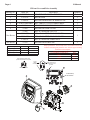
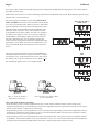
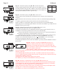
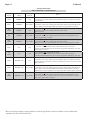
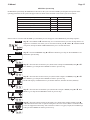
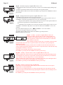
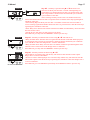
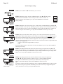
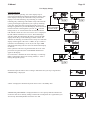
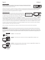
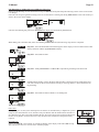
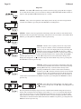
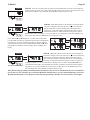
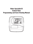
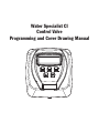
Water Specialist CI
Control Valve
Programming and Cover Drawing Manual
Page 2
CI Manual
CI Manual
Page 3
Table of Contents
CI Front Cover and Drive Assembly .......................................................................................................................4
OEM General Instructions .......................................................................................................................................5
OEM Cycle Sequence ..............................................................................................................................................6
OEM Softener System Setup .................................................................................................................................11
Setting Options Table.............................................................................................................................................14
OEM Filter System Setup ......................................................................................................................................15
Installer Display Settings .......................................................................................................................................18
User Display Settings ............................................................................................................................................19
Diagnostics ............................................................................................................................................................22
Valve History .........................................................................................................................................................24
Page 4
CI Manual
CI Front Cover and Drive Assembly
Drawing No.
1
2
3
4
5
6
Order No.
V3175CI-01
V3107-01
V3106-01
V3108CI-06BOARD
V3110
V3109
V3186
V3186EU
V3186UK
V3186-01
V3178
Not Shown
Not Shown
AC Adapter
Supply Voltage
Supply Frequency
Output Voltage
Output Current
U.S.
120 V AC
60 Hz
12 V AC
500 mA
Description
WS1CI FRONT COVER ASSEMBLY
WS1 MOTOR
WS1 DRIVE BRACKET & SPRING CLIP
WS1 THRU2L/2 CI PCB XMEGA REPL
WS1 DRIVE REDUCING GEAR 12X36
WS1 DRIVE GEAR COVER
WS1 AC ADAPTER 120V-12V
WS1 AC ADAPTER 220-240V-12V EU
WS1 AC ADAPTER 220-240V-12V UK
WS1 AC ADAPTER CORD ONLY
WS1 DRIVE BACKPLATE
Quantity
1
1
1
1
3
1
1
1
Relay Specifications: 12V DC Relay with a coil resistance not less than
80 ohms. If mounting relay under the cover check for proper mounting
dimensions on the backplate.
Wiring for Correct On/Off Operation
PC Board Relay Terminal Block
Relay
RLY 1
Coil + COM
Coil +
RLY 2
Coil -
International
230V AC
50 Hz
12 V AC
500 mA
When replacing the battery, align
positives and push down to fully seat.
Correct
Battery
Orientation
Battery replacement is
3 volt lithium coin cell
type 2032.
4
Battery Fully Seated
PC Board Relay
Terminal Block
1
6
5
3
2
CI Manual
Page 5
OEM General Instructions
The control valve offers multiple procedures that allow the valve to be modified to suit the needs of the installation. These
procedures are:
•
•
•
•
•
•
•
OEM Cycle Sequence
OEM Softener System Setup
OEM Filter System Setup
Installer Display Settings
User Display Settings
Diagnostics
Valve History
Once the OEM Cycle Sequence has been set, the other procedures can be accessed in any order. Details on each of the procedures
are provided on the following pages.
To “lock out” access to diagnostic and valve history displays and modifications to settings except hardness, day override, time of
regeneration and time of day by anyone but the manufacturer, press ▼, NEXT, ▲, and SET CLOCK in sequence after settings
are made. To “unlock”, so other displays can be viewed and changes can be made, press ▼, NEXT, ▲, and SET CLOCK in
sequence.
When in operation normal user displays such as time of day, volume remaining before regeneration, present flow rate or days
remaining before regeneration are shown. When stepping through a procedure, if no buttons are pressed within five minutes, the
display returns to a normal user display. Any changes made prior to the five minute time out are incorporated.
To quickly exit OEM Softener Setup, OEM Filter Setup, Installer Display Settings, Diagnostics or Valve History press SET
CLOCK. Any changes made prior to the exit are incorporated.
When desired, all programming and all information in Diagnostics may be reset to defaults when the valve is installed in a
new location. To reset to defaults, press NEXT and ▼ simultaneously to go to the Softening/Filtering screen. Press ▲ and
▼ simultaneously to reset diagnostic values and all programming to defaults. Screen will return to User Display.
Sometimes it is desirable to have the valve initiate and complete two regenerations within 24 hours and then return to the preset
regeneration procedure. It is possible to do a double regeneration if the control valve is set to “NORMAL” or “NORMAL + on 0”
in OEM Softener System Setup or OEM Filter System Setup. To do a double regeneration:
1. Press the REGEN button once. REGEN TODAY will flash on the display.
2. Press and hold the REGEN button for three seconds until the valve regeneration initiates.
Once the valve has completed the immediate regeneration, the valve will regenerate one more time at the preset regeneration time.
For Valve Type 1.0 , press and hold SET CLOCK and ▲ for about 3 seconds to initiate an exchange of the tank in Service without cycling the regeneration valve. After tank switch, days remaining and capacity remaining status is retained for each tank until
the next regeneration.
Prior to selecting the upflow regeneration cycle, verify that the correct body, main piston, regenerant piston and stack are being
used, and that the injector plug(s) are in the correct location. Refer to the Service Manual for drawings and part numbers.
Page 6
CI Manual
OEM Cycle Sequence
OEM Cycle Sequence instructions allows the OEM to set the order of
the cycle. The OEM Softener System Setup or the OEM Filter System
Setup allow the OEM to set how long cycles will last. The OEM may
choose up to 9 cycles in any order.
Cycle Options
BACKWASH DN BRINE
FILL
RINSE
END
SOFTENING
OR FILTERING
UP BRINE
END must be used as the last cycle option. The SERVICE cycle
should only be used in brine prefill applications.
The following is an example of how to set a valve so that when regeneration is initiated BACKWASH occurs first, dn BRINE
occurs second, RINSE occurs third, and FILL occurs fourth.
STEP 1CS
Step 1CS – Press NEXT and ▼ simultaneously for 3 seconds and release. Then press NEXT and ▼
simultaneously for 3 seconds and release. If screen in Step 2CS does not appear in 5 seconds the lock
on the valve is activated. To unlock press ▼, NEXT, ▲, and SET CLOCK in sequence, then press
NEXT and ▼ simultaneously for 3 seconds and release. Then press NEXT and ▼ simultaneously for
3 seconds and release.
STEP 2CS
Step 2CS – Use ▲ or ▼ to select 1.0 for WS1 valve, 1.25 for WS1.25 valve, 1.5 for WS1.5 valve, 2.0
for WS2 or 2.0L for a WS2L valve1, 1.0 for a twin valve.
Note: When using the WS2 valve, if “2.0L” is set instead of “2.0”, when the valve is in regeneration
and the piston drives to the “DRAW” cycle the piston will stall and generate an error code. Clear the
error code by pressing “NEXT” and “REGEN” buttons simultaneously until the valve resets, then
re-program valve to proper valve type setting. Press NEXT to go to Step 3CS. Press REGEN to exit
OEM cycle sequence.
STEP 3CS
Step 3CS – When 2.0 or 2.0L is selected, an additional screen will appear.
It is used to select which size flow meter is to be used with the valve, 1.5”,
2.0” or 3.0”. Variable meter pulses of 0.1-150.0 PPL can also be selected.
Press NEXT to go to Step 4CS. Press REGEN to return to previous step.
¹ When using the WS2 control valve, the circuit board software must have meter selection choices of 2.0 and 2.0L. The WS2 valve must be set
for the 2.0 meter selection during programming. If the software version does not have both the 2.0 and 2.0L selections, consult your equipment
supplier for a replacement circuit board. When using the WS2L valve with older version software that does not have both 2.0 and 2.0L selection
choices, the valve must be set to 2.0 if using a 2” meter or 1.5 if using a 1.5” meter during programming. If a WS2L valve is being used with
newer version software that has both 2.0 and 2.0L selection choices, the valve must be set for 2.0L during programming.
CI Manual
Page 7
STEP 4CS
Step 4CS – Allows selection of one of the following using ▲ or ▼:
• the Control Valve to have no hard water bypass;
• the Control Valve to act as an alternator; or
• the Control Valve to have a separate source during the regeneration cycle; or
• the Control Valve to operate with the Clack System Controller.
Select OFF when none of these features are used.
This display will not appear if 1.0 was selected in Step 2CS.
Only use Clack No Hard Water Bypass Valves or Clack Motorized Alternating Valves (MAV) with
these selections. Clack No Hard Water Bypass Valves (1” or 1.25” V3070FF or V3070FM) are not
designed to be used with the alternator or separate source functions.
Configuring the Control Valve for No Hard Water Bypass Operation:
Select nHbP for control operation. For no hard water bypass operation the three wire communication
connector is not used.
Selection requires that a connection to MAV or a Clack No Hard Water Bypass Valve is made to the
two pin connector labeled MAV located on the printed circuit board. If using a MAV, the A port of the
MAV must be plugged and the valve outlet connected to the B port. When set to nHbP the MAV will
be driven closed before the first regeneration cycle that is not FILL or SOFTENING or FILTERING,
and be driven open after the last regeneration cycle that is not FILL.
NOTE: If the control valve enters into an error state during regeneration mode, the no hard water
bypass valve will remain in its current state until the error is corrected and reset.
Configuring the Control Valve for Separate Source Operation:
Select SEPS for control operation. For separate source operation the three wire communication
connector is not used.
Selection requires that a connection to a Clack Motorized Alternator Valve (MAV) is made to the
two pin connector labeled MAV located on the printed circuit board. The C port of the MAV must be
connected to the valve inlet and the A port connected to the separate source used during regeneration.
The B port must be connected to the feed water supply.
When set to SEPS the MAV will be driven closed before the first regeneration cycle, and be driven
open after the last regeneration cycle.
NOTE: If the control valve enters into an error state during regeneration mode, the MAV will remain
in its current state until the error is corrected and reset.
Selecting the Control Valve to act as an alternator:
Software Rev Level 320.0 and higher = Use 3-wire Interconnect Cable for all communication between units.
Software Rev Level 319.5 and lower = Use 2-wire Interconnect Cables for twin alternators with independent flow meters.
Prior to starting the programming steps, connect the interconnect cable to each control valve board’s three pin connector labeled ‘COMM
CABLE’. Also connect the meter cord to either control valve to the three pin connector labeled ‘METER’.
Softener Valve Programming Steps
Set to ALT A
Set to ALT b
Connect ALT A valve to the MAV’s A port and
Connect ALT b valve to the MAV’s B port. No
OEM Cycle Sequence
Step 4CS
connect the MAV’s two pin wire connector to the
connections between the ALT b valve and the
two pin connector labeled “DRIVE” on the ALT
MAV are made.
A valve
Softener System
Step 7S
Set Volume Capacity
Set Volume Capacity
Setup
Softener System
Step 8S
Set to ‘AUTO’
Set to ‘AUTO’
Setup
Softener System
Step 9S
Set regeneration time option to ‘on 0’.
Set regeneration time option to ‘on 0’.
Setup
Installer Display
Step 4I
Set Day Over ride to “oFF”
Set Day Over ride to “oFF”
Setting
Page 8
CI Manual
If set up for a filter, in Step 7F set Volume Capacity in M3; in Step 8F select Regeneration Time Option “on 0”; and in Step 4I
select Day Override “oFF”.
NOTE: If the control valve is in an error state during regeneration mode the MAV will close the B port and keep open the A port
until the error is corrected and reset.
For Clack Corporation alternator systems using WS1, WS1.25,
WS1.5, and WS2L valves there will be an option to delay the last
two cycles of regeneration (only “Rinse” and “Fill”). This feature
splits the regeneration into two portions. The first portion of the
regeneration will start immediately and all programmed cycles
before the “Rinse” and “Fill” cycles will be performed. After
all programmed cycles before “Rinse” and “Fill” are completed
the control valve will drive to the service position (displaying
“Delayed Rinse + Fill Pending”). When the volume of the online unit is depleted to 10% of its programmed capacity, the
control valve will be triggered to finish the second portion of the
regeneration. Once “Rinse” and “Fill” are completed, the valve
will re-enter Standby mode until requested to come on-line for
Service.
WS1, WS1.25, WS1.5,
WS2L Valves
For Clack Corporation alternator systems using the WS2 valve,
when NEXT is pressed after selecting ALT A or ALT b, a display
will allow the user to set the amount of pre-service rinse time for
the stand by tank just prior to returning to service. With 1.0 set,
this same display appears and is set in a similar manner.
WS2
Valve
Retracted
Extended
Valve “A” in Service Position =
MAV piston rod Retracted
Valve “B” in Service Position = MAV
piston rod Extended
Note: Clack Twin Alternator Operations
• Twin alternating systems can be programmed with a day override setting combined with the normal volume-based
regeneration programming. A twin alternating system in this configuration will then regenerate based on the volume used or
the day override if there is a period of low water usage.
• Twin alternating systems can be programmed as a time clock only based regenerating system. In this configuration, the days
remaining are counted only on the unit that is in service. The unit in Stand-by Mode only notes days in diagnostics, which
results in time clock only twin regeneration initiation.
• Twin alternating systems can be programmed for a delayed regeneration time. The system will allow an immediate transfer
of the MAV to switch tanks and place a fully regenerated unit in service once a unit becomes exhausted. The exhausted unit
will then be placed into Stand-by Mode and allowed to have a delayed regeneration at the pre-set time.
CI Manual
Page 9
Configuring the Control Valve to operate with Clack System Controller:
Select SYS to link the Control Valve to the Clack System Controller. For communication between
the Control Valve and the System Controller, a three-wire communication cable is required.
Press NEXT to go to Step 5CS. Press REGEN to return to previous step.
STEP 5CS Step 5CS – Allows selection of one of the following using ▲ or ▼:
• an outside signal to initiate a regeneration;
• an outside signal to prevent or delay regeneration.
Selection only matters if a connection is made to the two pin connector labeled DP SWITCH located on
the printed circuit board. Following is an explanation of the options:
OFF - Feature not used.
NOTE: In a twin alternating system each control must have a separate dP signal or dP switch.
One dP signal or one dP switch cannot be used for both controls.
dPon0 – If the dP switch is closed for an accumulative time of 2 minutes a regeneration will be
signaled to the unit. In a twin alternating system the MAV will transition first to switch units so that
the signaled unit can start regeneration. After the MAV has fully transitioned, the regeneration begins
immediately. Note: For WS1 – WS2L control valves programmed for twin alternating: if the dP function
“dPon0” is set, the Delayed Rinse and Fill feature is not available.
dPdEL – If the dP switch is closed for an accumulative time of 2 minutes a regeneration will occur at
the scheduled delayed regeneration time. In a twin alternating system, once the dP switch is triggered
the PC board will display REGEN TODAY and switch tanks immediately. At the Delayed Regeneration
Time, the triggered unit will then regenerate. Note: For WS1 – WS2L control valves programmed for
twin alternating: if the dP function “dPdEL” is set, the Delayed Rinse and Fill feature is not available.
HoLd – If the dP switch is closed a regeneration will be prevented from occurring while there is switch
closure. In a twin alternating system the regeneration of a unit can be prevented upon switch closure.
If the unit depletes the capacity down to zero, it will not be allowed to switch tanks to regenerate until
the switch is open. Note: For WS1 – WS2L control valves programmed for twin alternating the Delayed
Rinse and Fill feature can be set in conjunction with the “HoLd” if desired.
Press NEXT to go to Step 6CS. Press REGEN to return to previous step.
Page 10
CI Manual
STEP 6CS
Step 6CS – Determine the measurement to calculate volumetric capacity. The
choices are:
ppm
parts per million
FH
French degrees
dH
German degrees
NOTE: If control is going to be used in a filter application none of these
settings can be used.
Press NEXT to go to Step 7CS. Press REGEN to return to previous step.
STEP 7CS
Step 7CS – Press ▲ or ▼ until BACKWASH appears. Press NEXT to go to Step 8CS. Press REGEN
to return to previous step.
STEP 8CS
Step 8CS - Press ▲ or ▼ until BRINE appears. NOTE: Prior to selecting the upflow regeneration
cycle, verify that the correct body, main piston, regenerant piston and stack are being used, and that the
injector plug(s) are in the correct location. Refer to the Service Manual for drawings and part numbers.
Press NEXT to go to Step 9CS. Press REGEN to return to previous step.
STEP 9CS
Step 9CS - Press ▲ or ▼ until RINSE appears. Press NEXT to go to Step 10CS. Press REGEN to
return to previous step.
STEP 10CS
Step 10CS - Press ▲ or ▼ until FILL appears. Press NEXT to go to Step 11CS. Press REGEN to
return to previous step.
STEP 11CS
Step 11CS - Press ▲ or ▼ until END appears. Press NEXT to go to Step 12CS. Press REGEN to
return to previous step.
STEP 12CS
Step 12CS - Fill Units: If set as a softener, if Step 2CS is set to 1.5, and FILL is part of the
Regeneration Cycle Sequence, FILL UNITS of MIN or kg can be selected.
Press NEXT to exit OEM Cycle Sequence. Press REGEN to return to
previous step.
RETURN TO NORMAL MODE
CI Manual
Page 11
OEM Softener System Setup
In OEM Softener System Setup the OEM chooses the time for the cycles selected in OEM Cycle Sequence and specifies other
operating parameters for the system. The upper and lower limits of the allowable values for the cycles are as follows:
Cycle Options
Backwash
Rinse (fast)
dn Brine (combination of brining and slow rinse)
up Brine (combination of brining and slow rinse)
Fill for 1”, 1.25”, 1.5”and 2.0L
Fill for WS2 valves or WS1.5 set to MIN
Service
Units
Minutes
Minutes
Minutes
Minutes
kg
Minutes
Minutes
Lower/Upper Limit
1 to 120
1 to 120
1 to 180
1 to 180
0.05 to 90.00
0.1 to 99.0
1 to 480
Since no time is associated with the END cycle, the END cycle will not appear in the OEM Softener System Setup sequence.
STEP 1S
Step 1S – Press NEXT and ▼ simultaneously for 3 seconds and release. If screen in Step 2S does not
appear in 5 seconds the lock on the valve is activated. To unlock press ▼, NEXT, ▲, and SET CLOCK
in sequence, then press NEXT and ▼ simultaneously for 3 seconds and release.
STEP 2S
Step 2S – Choose SOFTENING using ▲ or ▼. Press NEXT to go to Step 3S. Press REGEN to exit
OEM Softener System Setup.
STEP 3S
Step 3S – Select the time for the first cycle (which in this example is BACKWASH) using ▲ or ▼.
Press NEXT to go to Step 4S. Press REGEN to return to previous step.
STEP 4S
Step 4S – Select the time for the second cycle (which in this example is dn BRINE) using ▲ or ▼.
Press NEXT to go to Step 5S. Press REGEN to return to previous step.
NOTE: The display will flash between cycle number and time, and brine direction (dn).
STEP 5S
Step 5S – Select the time for the third cycle (which in this example is RINSE) using ▲ or ▼. Press
NEXT to go to Step 6S. Press REGEN to return to previous step.
STEP 6S
Step 6S – Select the kg or MIN for the fourth cycle (which in this example is FILL) using ▲ or ▼.
When both 2.0 and 2.0L are options in Step 2CS, and 2.0 is selected, or MIN is selected in Step 12CS,
FILL is in minutes. WS2 valves are shipped from the factory with a refill flow contol of 2.2 gpm (8.3
lpm). Press NEXT to go to Step 7S. Press REGEN to return to previous step.
Page 12
CI Manual
STEP 7S
Step 7S – Set System Capacity using ▲ or ▼. See chart. The System
Capacity setting should be based on the volume of resin and Kg of salt fill
set in Step 6S. When using ppm, dH, or FH the system capacity and hardness
levels entered are used to determine the Volume Capacity. Press NEXT to go
to Step 8S. Press REGEN to return to previous step.
Setting
Units
PPM
Kg of
CaCO3
dH or FH
M3
STEP 8S
Step 8S – Set Volume Capacity using ▲ or ▼. If value is set to:
• AUTO capacity will be automatically calculated and reserve capacity will be automatically
estimated;
• oFF regeneration will be based solely on the day override set (see Installer Display/Settings Step
4I);
• a number, regeneration initiation will be based on the value specified (in M3); or
If oFF or a number is used, hardness display will not be allowed to be set in Installer Display
Settings Step 2I & 3I. See Setting Options Table for more detail. Press NEXT to go to Step 9S. Press
REGEN to return to previous step.
STEP 9S
Step 9S – Set Regeneration Time Options using ▲ or ▼. If value is set to:
• NORMAL means regeneration will occur at the preset time;
• on 0 means regeneration will occur immediately when the volume capacity reaches 0 (zero); or
• NORMAL + on 0 means regeneration will occur at one of the following:
— the preset time when the volume capacity falls below the reserve or the specified number of
days between regenerations is reached whichever comes first; or
— immediately after 10 minutes of no water usage when the volume capacity reaches 0 (zero).
NORMAL is the default if Step 4CS is set to ALT A or ALT b, and NORMAL + on 0 is not
available. On 0 is the default if Step 2CS is set to 1.0 , and NORMAL + on 0 is not available.
This step will not appear if Step 8S is set to off or Step 4CS is set to SYS.
See Setting Options Table for more detail. Press NEXT to go to Step 10S. Press REGEN to return to
previous step.
STEP 10S
Step 10S – Set Relay 1 operation using ▲ or ▼. The choices are:
• Set Time on: Relay activates after a set time at the beginning of a
regeneration cycle and then deactivates after a set period of time. The
start of regeneration is defined as the first backwash cycle or Dn brine/Up
brine cycle, whichever comes first.
• Set L Softening on: Relay activates after a set number of liters has
been treated and then deactivates after a set period of time or after the meter stops registering flow,
whichever comes first.
• Set L Softening Regen on: Relay activates after a set number of liters have been used while in
service or during regeneration and then deactivates after a set period of time or after the meter stops
registering flow, whichever comes first.
• Set Off: If set to Off, Steps 11S and 12S will not be shown.
Press NEXT to go to Step 11S. Press REGEN to return to previous step.
STEP 11S
Step 11S – Set Relay 1 Actuation Time or Liters using ▲ or ▼. The choices are:
• Relay Actuation Time: After the start of a regeneration the amount of time that should pass prior
to activating the relay. The start of regeneration is defined as the first backwash cycle or Dn brine
cycle, whichever comes first. Ranges from 1 second to 200 minutes.
• Relay Actuation Liters: Relay activates after a set number of Liters has passed through the meter
when the valve is in the Service mode. Ranges from 1 to 200 Liters.
Press NEXT to go to Step 12S. Press REGEN to return to previous step.
CI Manual
Page 13
STEP 12S
Step 12S – Set Relay 1 Deactivate Time using ▲ or ▼.
• If Set Time on is selected in Step 10S the relay will deactivate after the time set has expired.
Ranges from 1 second to 200 minutes.
• If Set L on or Set L Softening Regen on is selected in Step 10S the relay will deactivate after the
time set has expired or after the meter stops registering flow, whichever comes first. Ranges from 1
second to 20 minutes.
Press NEXT to go to Step 13S. Press REGEN to return to previous step.
STEP 13S
Step 13S – Set Relay 2 operation using ▲ or ▼. The choices are:
• Set Time on: Relay activates after a set time at the beginning of a
regeneration cycle and then deactivates after a set period of time. The
start of regeneration is defined as the first backwash cycle or Dn brine
cycle, whichever comes first.
• Set L Softening on: Relay activates after a set number of liters has
been treated and then deactivates after a set period of time or after the meter stops registering flow,
whichever comes first.
• Set L Softening Regen on: Relay activates after a set number of liters have been used while in
service or during regeneration and then deactivates after a set period of time or after the meter stops
registering flow, whichever comes first.
• Error: Relay closes whenever the control enters the Error Mode, and immediately deactivates when
the error mode is exited.
• Set Off: If set to Off, Steps 14S and 15S will not be shown.
Press NEXT to go to Step 14S. Press REGEN to return to previous step.
STEP 14S
Step 14S – Set Relay 2 Actuation Time or Liters using ▲ or ▼. The choices are:
• Relay Actuation Time: After the start of a regeneration the amount of time that should pass prior to
activating the relay. The start of regeneration is defined as the first backwash cycle or Dn brine/Up
brine cycle, whichever comes first. Ranges from 1 second to 200 minutes.
• Relay Actuation Liters: Relay activates after a set number of Liters has passed through the meter
when the valve is in the Service mode. Ranges from 1 to 200 Liters.
Press NEXT to go to Step 15S. Press REGEN to return to previous step.
STEP 15S
Step 15S – Set Relay 2 Deactivate Time using ▲ or ▼.
• If Set Time on is selected in Step 13S the relay will deactivate after the time set has expired.
Ranges from 1 second to 200 minutes.
• If Set L on or Set L Softening Regen on is selected in Step 13S the relay will deactivate after the
time set has expired or after the meter stops registering flow, whichever comes first. Ranges from 1
second to 20 minutes.
Press NEXT to go to Step 16S. Press REGEN to return to previous step.
STEP 16S
RETURN TO NORMAL MODE
Step 16S – Set Low Salt Warning using ▲ or ▼. If value is set to:
• oFF, no low salt level warning will appear for the user; or
• a specific value, “FILL SALT” will flash on the display when the
calculated remaining kg of salt falls below that level. Allowable values
range from 5 to 400 Kg in 5 Kg increments. When both 2.0 and 2.0L are
options in Step 2CS and 2.0 is selected, or MIN is selected in Step 12CS this step is skipped and not
active.
Press NEXT to exit OEM Softener System Setup. Press REGEN to return to previous step.
Page 14
CI Manual
Setting Options Table
Filters should only use shaded options
Volume
Capacity
Regeneration Time
Option
Day
Override
AUTO
NORMAL
oFF
Reserve capacity automatically estimated.
Regeneration occurs when volume capacity falls below the reserve capacity at the next
Regen Set Time.
AUTO
NORMAL
Any number
Reserve capacity automatically estimated.
Regeneration occurs at the next Regen Set Time when volume capacity falls below the
reserve capacity or the specified number of days between regenerations is reached.
Any
number
NORMAL
oFF
oFF
NORMAL
Any number
Reserve capacity not automatically estimated.
Regeneration occurs at the next Regen Set Time when the specified number of days
between regenerations is reached.
Any
number
NORMAL
Any number
Reserve capacity not automatically estimated.
Regeneration occurs at the next Regen Set Time when volume
capacity reaches 0 or the specified number of days between regenerations is reached.
Reserve capacity not automatically estimated.
Regeneration occurs at the next Regen Set Time when volume
capacity reaches 0.
AUTO
on 0
oFF
Reserve capacity NOT automatically estimated.
Regeneration occurs immediately when volume capacity reaches 0. Time of
regeneration will not be allowed to be set because regeneration will always occur when
volume capacity reaches 0.
Any
number
on 0
oFF
Reserve capacity NOT automatically estimated.
Regeneration occurs immediately when volume capacity reaches 0. Time of
regeneration will not be allowed to be set because regeneration will always occur on 0.
oFF
Reserve capacity automatically estimated.
Regeneration occurs when volume capacity falls below the reserve capacity at the next
Regen Set Time or regeneration occurs after 10 minutes of no water usage when volume
capacity reaches 0.
Any number
Reserve capacity automatically estimated.
Regeneration occurs at the next Regen Set Time when volume capacity falls below the
reserve capacity or the specified number of days between regenerations is reached or
regeneration occurs after 10 minutes of no water usage when volume capacity reaches 0.
Any number
Reserve capacity not automatically estimated.
Regeneration occurs at the next Regen Set Time when the specified number of days
between regenerations is reached or regeneration occurs after 10 minutes of no water
usage when volume capacity reaches 0.
AUTO
AUTO
Any
number
2
Result2
NORMAL on 0
NORMAL on 0
NORMAL on 0
Reserve Capacity estimate is based on history of water usage. Reserve Capacity estimate is not available with
alternator systems or Twin Tank Valve.
CI Manual
Page 15
OEM Filter System Setup
In OEM Filter System Setup the OEM chooses the time for the cycles selected in OEM Cycle Sequence and specifies other
operating parameters for the system. The upper and lower limits of the allowable values for the cycles are as follows:
Cycle Options
Backwash
Rinse (fast)
dn Brine (combination of regenerant and slow rinse)
Fill for all valves except WS2
Fill for WS2 Valves
Service
Units
Minutes
Minutes
Minutes
Liters
Minutes
Minutes
Lower/Upper Limit
1 to 120
1 to 120
1 to 180
0.2 to 76.00
0.01 to 99.0
1 to 480
NOTE: Fill is in liters (except for WS2).
Since no time is associated with the END cycle, the END cycle will not appear in the OEM Filter System Setup sequence.
STEP 1F
Step 1F – Press NEXT and ▼ simultaneously for 3 seconds and release. If screen in Step 2F does not
appear in 5 seconds the lock on the valve is activated. To unlock press ▼, NEXT, ▲, and SET CLOCK
in sequence, then press NEXT and ▼ simultaneously for 3 seconds and release.
STEP 2F
Step 2F – Choose FILTERING using ▲ or ▼. Press NEXT to go to Step 3F. Press REGEN to exit
OEM Filter System Setup.
STEP 3F
Step 3F – Select the time for the first cycle (which in this example is BACKWASH) using ▲ or ▼.
Press NEXT to go to Step 4F. Press REGEN to return to previous step.
STEP 4F
Step 4F – Select the time for the second cycle (which in this example is dn BRINE) using ▲ or ▼.
Press NEXT to go to Step 5F. Press REGEN to return to previous step.
NOTE: The display will flash between cycle number and time, and brine direction (dn Brine).
STEP 5F
Step 5F – Select the time for the third cycle (which in this example is RINSE) using ▲ or ▼. Press
NEXT to go to Step 6F. Press REGEN to return to previous step.
STEP 6F
Step 6F – Select the volume in liters for the fourth cycle (which in this example is FILL) using ▲
or ▼. When both 2.0 and 2.0L are options in Step 2CS, and 2.0 is selected, FILL is in minutes. WS2
valves are shipped from the factory with a refill flow control of 2.2 gpm (8.3 lpm). Press NEXT to go
to Step 7F. Press REGEN to return to previous step.
Page 16
CI Manual
STEP 7F
Step 7F – Set Volume Capacity using ▲ or ▼. If value is set to:
• oFF regeneration will be based solely on the day override set (see Installer Display/Settings Step
4I); or
• a number, regeneration initiation will be based off the value specified (in M3).
See Setting Options Table for more detail. Press NEXT to go to Step 8F. Press REGEN to return to
previous step.
STEP 8F
Step 8F – Set Regeneration Time Options using ▲ or ▼. If value is set to:
• NORMAL means regeneration will occur at the preset time;
• on 0 means regeneration will occur immediately when the volume capacity reaches 0 (zero); or
• NORMAL + on 0 means regeneration will occur at one of the following:
— the preset time when the volume capacity falls below the reserve or the specified number of
days between regenerations is reached whichever comes first;
or
— immediately after 10 minutes of no water usage when the volume capacity reaches 0 (zero).
“NORMAL” is the default if Step 4CS is set to ALT A or ALT B, and “NORMAL + on 0” is not
available.
On 0 is the default if Step 2CS is set to 1.0 , and NORMAL + on 0 is not available.
This step will not appear if Step 7F is set to “oFF”.
See Setting Options Table for more detail. Press NEXT to go to Step 9F. Press
REGEN to return to previous step.
STEP 9F
Step 9F – Set Relay 1 operation using ▲ or ▼. The choices are:
• Set Time on: Relay activates after a set time at the beginning of a
regeneration cycle and then deactivates after a set period of time. The
start of regeneration is defined as the first backwash cycle or Dn brine
cycle, whichever comes first.
• Set L Filtering on: Relay activates after a set number of liters has been
treated and then deactivates after a set period of time or after the meter stops registering flow,
whichever comes first.
• Set L Filtering Regen on: Relay activates after a set number of liters have been used while in
service or during regeneration and then deactivates after a set period of time or after the meter stops
registering flow, whichever comes first.
• Set Off: If set to Off, Steps 10F and 11F will not be shown.
Press NEXT to go to Step 10F. Press REGEN to return to previous step.
STEP 10F
Step 10F – Set Relay 1 Actuation Time or Liters using ▲ or ▼. The choices are:
• Relay Actuation Time: After the start of a regeneration the amount of time that should pass prior
to activating the relay. The start of regeneration is defined as the first backwash cycle or Dn brine
cycle, whichever comes first. Ranges from 1 second to 200 minutes.
• Relay Actuation Liters: Relay activates after a set number of Liters has passed through the meter
when the valve is in the Service mode. Ranges from 1 to 200 Liters.
Press NEXT to go to Step 11F. Press REGEN to return to previous step.
STEP 11F
Step 11F – Set Relay 1 Deactivate Time using ▲ or ▼.
• If Set Time on is selected in Step 10S the relay will deactivate after the time set has expired.
Ranges from 1 second to 200 minutes.
• If Set L on or Set L Filtering Regen on is selected in Step 9F the relay will deactivate after the
time set has expired or after the meter stops registering flow, whichever comes first. Ranges from 1
second to 20 minutes.
Press NEXT to go to Step 12F. Press REGEN to return to previous step.
CI Manual
Page 17
STEP 12F
Step 12F – Set Relay 2 operation using ▲ or ▼. The choices are:
• Set Time on: Relay activates after a set time at the beginning of a
regeneration cycle and then deactivates after a set period of time. The
start of regeneration is defined as the first backwash cycle or Dn brine
cycle, whichever comes first.
• Set L Filtering on: Relay activates after a set number of liters has
been treated and then deactivates after a set period of time or after the meter stops registering flow,
whichever comes first.
• Set L Filtering Regen on: Relay activates after a set number of liters have been used while in
service or during regeneration and then deactivates after a set period of time or after the meter stops
registering flow, whichever comes first.
• Error: Relay closes whenever the control enters the Error Mode, and immediately deactivates when
the error mode is exited.
• Set Off: If set to Off, Steps 13F and 14F will not be shown.
Press NEXT to go to Step 13F. Press REGEN to return to previous step.
STEP 13F
Step 13F – Set Relay 2 Actuation Time or Liters using ▲ or ▼. The choices are:
• Relay Actuation Time: After the start of a regeneration the amount of time that should pass prior
to activating the relay. The start of regeneration is defined as the first backwash cycle or Dn brine
cycle, whichever comes first. Ranges from 1 second to 200 minutes.
• Relay Actuation Liters: Relay activates after a set number of Liters has passed through the meter
when the valve is in the Service mode. Ranges from 1 to 200 Liters.
Press NEXT to go to Step 14F. Press REGEN to return to previous step.
STEP 14F
Step 14F – Set Relay 2 Deactivate Time using ▲ or ▼.
• If Set Time on is selected in Step 13S the relay will deactivate after the time set has expired.
Ranges from 1 second to 200 minutes.
• If Set L on or Set L Softening Regen on is selected in Step 13S the relay will deactivate after the
time set has expired or after the meter stops registering flow, whichever comes first. Ranges from 1
second to 20 minutes.
Press NEXT to go to exit OEM Filter System Setup. Press REGEN to return to previous step.
RETURN TO NORMAL MODE
Page 18
CI Manual
Installer Display Settings
STEP 1I
STEP 1I - Press NEXT and ▲ simultaneously for 3 seconds.
STEP 2I
STEP 2I – Hardness: Set the amount of influent hardness using ▲ or ▼. This display
will not be shown if FILTER is selected in Step 2F OR if oFF or a number was
selected in Step 8S. Press NEXT to go to step 3I. Press REGEN to exit Installer
Display Settings.
STEP 3I
STEP 3I – Hardness 2: If using a mixing valve, set the amount of effluent hardness using ▲ or ▼.
Range of available values may vary depending on system capacity selected and hardness selected in
Step 2I. This display will not be shown if FILTER is selected in Step 2F OR oFF or a number was
selected in Step 8S. Press NEXT to go to Step 4I. Press REGEN to return to previous step.
STEP 4I
RETURN TO
NORMAL MODE
Units
Available
PPM
FH
dH
STEP 4I – Day Override: When volume capacity is set to oFF, sets the number of days between
regenerations. When volume capacity is set to AUTO or to a number, sets the maximum number of
days between regenerations. If value set to oFF, regeneration initiation is based solely on volume
used. If value is set as a number (allowable range from 1 to 28) a regeneration initiation will be
called for on that day even if sufficient volume of water were not used to call for a regeneration. Set
Day Override using ▲ or ▼:
• number of days between regeneration (1 to 28); or
• oFF.
See Setting Options Table for more detail on setup. Press NEXT to go to step 5I. Press REGEN to
return to previous step.
STEP 5I
STEP 5I – Next Regeneration Time (hour): Set the hour of day for regeneration using ▲ or ▼
buttons. The default time is 2:00. This display will show “REGEN on 0 m3” if “on 0” is selected in
Set Regeneration Time Option in OEM Softener System Setup or OEM Filter System Setup. Press
NEXT to go to step 6I. Press REGEN to return to previous step.
STEP 6I
STEP 6I – Next Regeneration Time (minutes): Set the minutes of day for regeneration
using ▲ or ▼. This display will not be shown if “on 0” is selected in Set Regeneration
Time Option in OEM Softener System Setup or OEM Filter System Setup. Press
NEXT to exit Installer Display Settings. Press REGEN to return to previous
step.
To initiate a manual regeneration immediately, press and hold the REGEN button for three seconds.
The system will begin to regenerate immediately. The control valve may be stepped through the
various regeneration cycles by pressing the REGEN button.
CI Manual
Page 19
User Display Settings
General Operation
When the system is operating, one of five displays may be
shown. Pressing NEXT will alternate between the displays. One
of the displays is always the current time of day. The second
display is one of the following: days remaining or volume
remaining. Days remaining is the number of days left before the
system goes through a regeneration cycle. Capacity remaining
is the cubic meters that will be treated before the system goes
REGEN TODAY will
through a regeneration cycle. The third display shows the current Flash if a regeneration
is expected “Tonight.”
treated water flow rate through the system. If 1.0 is selected
in Step 2CS, an “A” in front of the flow rate indicates that the
tank with the control valve on it is in service. If “b” is displayed,
the tank with the in/out head is in service. The fourth display
will show either dP or hold if the dP switch is closed. The fifth
display shows the kg of salt remaining or flashes “SALT” fill
when the calculated kg of salt falls below a safety level. The fifth
display will not appear if the valve is a WS2, set up as a filter or
if the Set Low Salt Warning is set to off (see last step in OEM
Softener System Setup). The user can scroll between the displays
as desired.
If the system has called for a regeneration that will occur at the
preset time of regeneration, the words REGEN TODAY will
appear on the display.
If a water meter is installed, the word “Softening” or “Filtering”
flashes on the display when water is being treated (i.e. water is
flowing through the system).
In Alternator Systems when a unit is waiting to initiate the first cycle step of regeneration,
“REGEN Pndg” is displayed.
“STbY” is displayed in Alternator Systems when a valve is in Standby state.
“REGEN Pndg FILL RINSE” is displayed whenever a zero-capacity tank has transferred to
an off-line state and is currently waiting to initiate the second portion of a regeneration cycle.
Viewed only when Delayed Rinse and Fill is set to ON.
or
Page 20
CI Manual
Regeneration Mode
Typically a system is set to regenerate at a time of low water usage. An example of a time with
low water usage is when a household is asleep. If there is a demand for water when the system is
regenerating, untreated water will be used.
When the system begins to regenerate, the display will change to include information about the step of the regeneration process
and the time remaining for that step to be completed. The system runs through the steps automatically and will reset itself to
provide treated water when the regeneration has been completed.
Manual Regeneration
Sometimes there is a need to regenerate the system sooner than when the
REGEN TODAY will be
system calls for it, usually referred to as manual regeneration. There may displayed if a regeneration
be a period of heavy water usage because of guests or a heavy laundry day. is expected “Tonight.”
To initiate a manual regeneration at the preset delayed regeneration
time, when the regeneration time option is set to “NORMAL” or “NORMAL + on 0”, press and release “REGEN”. The words
“REGEN TODAY” will flash on the display to indicate that the system will regenerate at the preset delayed regeneration time. If
you pressed the “REGEN” button in error, pressing the button again will cancel the request. Note: If the regeneration time option
is set to “on 0” there is no set delayed regeneration time so “REGEN TODAY” will not activate if “REGEN” button is pressed.
To initiate a manual regeneration immediately, press and hold the “REGEN” button for three seconds. The system will begin to
regenerate immediately. The request cannot be cancelled.
Note: For softeners, if brine tank does not contain salt, fill with salt and wait at least two hours before regenerating.
Set Time of Day
The user can also set the time of day. Time of day should only need to be set after power outages lasting more than 24 hours, if
the battery has been depleted and a power outage occurs or when daylight saving time begins or ends. If a power outage lasting
more than 24 hours occurs, the time of day will flash on and off which indicates the time of day should be reset. If a power outage
lasts less then 24 hours and the time of day flashes on and off, the time of day should be reset and the non rechargeable battery
replaced.
STEP 1U
STEP 1U – Press SET CLOCK.
STEP 2U
STEP 2U - Current Time (hour): Set the hour of the day using ▲ or ▼. Press NEXT to go to
Step 3U.
STEP 3U
STEP 3U - Current Time (minutes): Set the minutes of the day using ▲ or ▼. Press NEXT to exit
Set Clock. Press REGEN to return to previous step.
RETURN TO NORMAL MODE
CI Manual
Page 21
Salt Remaining or Adding Salt (not available for WS2 valves)
If the Low Salt Warning was activated in the last step of OEM Softener System Setup the following screens will be viewed in the
User Display.
Note: The salt used per regeneration setting can be set in increments of 0.05 Kg, but the Kg REMAINING screen will round up or
down to the closest whole number.
Once the salt remaining has gone below the set point the display will automatically flash Salt Fill.
When adding salt to the brine tank (if the salt remaining feature is activated) the following steps must be completed:
STEP 1US
Step 1US – Press the NEXT button until SALT appears in the display. It does not matter if the SALT
display alternates with the Kg REMAINING display.
STEP 2US
Step 2US – Press SET CLOCK.
STEP 3US
Step 3US – Set Kg REMAINING: Use ▲ or ▼ to adjust the Kg remaining in the brine tank.
NOTE: Estimate the Kg of salt in the brine tank and add it to the amount of salt added to the brine
tank. The example at the left would indicate 100 Kg of salt being added to a brine tank that has 20
Kg remaining.
STEP 4US
Step 4US – Press SET CLOCK or NEXT to exit Adding Salt.
RETURN TO NORMAL MODE
Power Loss
If the power goes out, the system will keep time for 24 hours or until the battery is depleted. If a power
outage of more than 24 hours occurs, the time of day will flash on and off which indicates the time of
day should be reset. The system will remember the rest. If a power outage lasts less then 24 hours and
the time of day flashes on and off, the time of day should be reset and the non rechargeable battery
replaced.
Error Message
If the word “ERROR” and a number are alternately flashing on the display contact the OEM for help.
This indicates that the valve was not able to function properly.
Page 22
CI Manual
Diagnostics
STEP 1D
STEP 1D – Press ▲ and ▼ simultaneously for three seconds. If screen in step 2D does not appear
in 5 seconds the lock on the valve is activated. To unlock press ▼, NEXT, ▲, and SET CLOCK in
sequence, then press ▲ and ▼ simultaneously for 3 seconds.
STEP 2D
STEP 2D – Days, since last regeneration: This display shows the days since the last regeneration
occurred. Press NEXT to go to Step 3D. Press REGEN to exit Diagnostics.
STEP 3D
STEP 3D – Volume, since last regeneration: This display shows the volume of water that has been
treated since the last regeneration. This display will equal zero if a water meter is not installed. Press
NEXT to go to Step 4D. Press REGEN to return to previous step.
STEP 4D
STEP 4D – Volume, reserve capacity used for last 7 days: If the
valve is set up as a softener, a meter is installed and Set Volume
Capacity is set to “Auto,” this display shows 0 day (for today) and
flashes the reserve capacity. Pressing ▲ will show day 1 (which
would be yesterday) and flashes the reserve capacity used. Pressing
▲ again will show day 2 (the day before yesterday) and the reserve capacity. Keep pressing ▲ to
show the capacity for days 3, 4, 5 and 6. ▼ can be pressed to move backwards in the day series.
Display does not appear if 1.0 is selected in Step 2CS. Press NEXT at any time to go to Step 5D.
Press REGEN to return to previous step.
STEP 5D
STEP 5D - Volume, 63-day usage history: This display shows day
1 (for yesterday) and flashes the volume of water treated yesterday.
Pressing ▲ will show day 2 (which would be the day before
yesterday) and flashes the volume of water treated on that day.
Continue to press ▲ to show the maximum volume of water treated
for the last 63 days. If a regeneration occured on the day the word
“REGEN” will also be displayed. This display will show dashes if
a water meter is not installed. Press NEXT at any time to go to Step 6D. Press REGEN to return to
previous step.
STEP 6D
STEP 6D – Twin Tank Valve Transfer History only displays when
1.0 was selected in Step 2CS. Use ▲ or ▼ to scroll through the last
10 tank transfers.
The first position in the display ranges from 0 to 9 with the lowest number being the most recent
transfer. The second position in the display will be either “A” or “b”. If “A” then the tank with the
valve on it was in service, if “b” the tank with the in/out head on it was in service. The next three
digits represent the number of hours ago that the transfer occurred. The display alternates with the
volume that was treated before the tank transferred. Press NEXT at any time to go to Step 7D. Press
REGEN to return to previous step.
CI Manual
Page 23
STEP 7D
STEP 7D – Flow rate, maximum last seven days: The maximum flow rate in liters per minute that
occurred in the last seven days will be displayed. This display will equal zero if a water meter is not
installed. Press NEXT to go to Step 8D. Press REGEN to return to previous step.
STEP 8D
STEP 8D – MAV Drive History in the direction of extended piston
rod position. Display will not be shown if 1.0 is not selected in
Step 2CS and OFF is selected in Step 4CS. If the display does
appear up to a four digit number will appear after the “L” which
stands for latest and “A” which stands for average. Drive time is
measured in 1/100 of a second; i.e., a 17.10 second move is displayed as 1710. Press NEXT at any
time to go to Step 9D. Press REGEN to return to previous step.
Press and hold ▲ and ▼ buttons for 3 seconds while in Step 8D to
reset the MAV drive history in both the retracted and extended piston
rod position. To view the old MAV drive history data for retracted
and extended rod position press and hold SET CLOCK and ▲ while
in Step 8D. Press NEXT to advance display to the old MAV drive
history.
STEP 9D
RETURN TO NORMAL MODE
STEP 9D – MAV Drive History in the direction of retracted piston
rod position. Display will not be shown if 1.0 is not selected in Step
2CS and OFF is selected in Step 4CS. If the display does appear,
up to a four digit number will appear after the “L” which stands for
latest and “A” which stands for average. Drive time is measured in
1/100 of a second; i.e., a 17.15 second move is displayed as 1715. Press and hold ▲ and ▼ for 3
seconds while in Step 9D to reset the MAV drive history in both the extended and retracted piston
rod position. To view the old MAV drive history data see Step 8D. Press the NEXT button at any
time exit Diagnostics. Press REGEN to return to previous step.
When desired, all programming and all information in Diagnostics may be reset to defaults when the valve is installed in a
new location. To reset to defaults, press NEXT and ▼ buttons simultaneously to go to the Softening/Filtering screen. Press
▲ and ▼ simultaneously to reset diagnostic values and all programming to defaults. Screen will return to User Display.
Page 24
CI Manual
Valve History
STEP 1VH
STEP 1VH – Press ▲ and ▼ simultaneously for three seconds and release. Then press ▲ and ▼
simultaneously and release. If screen in step 2VH does not appear in 5 seconds the lock on the valve
is activated. To unlock press ▼, NEXT, ▲, and SET CLOCK in sequence, then press ▲ and ▼
simultaneously for 3 seconds and release. Then press ▲ and ▼ simultaneously and release.
STEP 2VH
STEP 2VH3 – Software version: This display shows the software version of the valve. Press the
NEXT button to go to Step3VH. Press REGEN to exit the valve history.
STEP 3VH
STEP 3VH – Days, total since start-up: This display shows the total days since startup. Press the
NEXT button to go to Step 4VH. Press REGEN to return to previous step.
STEP 4VH
STEP 4VH – Regenerations, total number since start-up: This display shows the total number of
regenerations that have occurred since startup. Press the NEXT button to go to Step 5VH. Press
REGEN to return to previous step.
STEP 5VH
STEP 5VH – Volume, total used since start-up: This display shows the total volume of water treated
since startup. This display will equal zero if a water meter is not installed. Press the NEXT button to
go to Step 6VH. Press REGEN to return to previous step.
STEP 6VH
STEP 6VH – Error Log: This display shows a history of the last 10 errors generated by the control
during operation. Press the ▲ or ▼ buttons to view each recorded error. Press the next button to exit
Valve History. Press REGEN to return to previous step.
RETURN TO NORMAL MODE
3
Values in steps 2VH through 6VH cannot be reset.
CI Manual
Page 25
Page 26
CI Manual
CI Manual
Page 27
Revision History:
1/23/2013
PAGE 9:
dPdEL – Revisions
PAGE 13:
2
Reserve Capacity estimate is based on history of water usage. Reserve Capacity estimate is not available with
alternator systems or Twin Tank Valve.
PAGE 20:
STEP 5D - revised drawing
PAGE 21:
STEP 8D – MAV Drive History in the direction of extended...
STEP 9D – MAV Drive History in the direction of retracted...
4/9/2013
PAGE 5:
For Valve Type 1.0 , press and hold SET and ▲ for about 3 seconds to initiate an exchange of the tank in Service without cycling
the regeneration valve. After tank switch, days remaining and capacity remaining status is retained for each tank until the next
regeneration.
11/7/2013
PAGE 4:
V3108CI-06BOARD WS1 THRU 2L/2 CI PCB XMEGA REPL
PAGE 5:
Prior to selecting the upflow regeneration cycle, verify that the correct body, main piston, regenerant piston and stack are being
used, and that the injector plug(s) are in the correct location. Refer to the Service Manual for drawings and part numbers.
PAGE 6:
Step 3CS - New displays.
Variable meter pulses of 0.1-150.0 PPG can also be selected.
PAGE 12:
Added Steps 10S-15S Relay 1 and 2 operations.
PAGE 16:
Added Steps 9F-14F Relay 1 and 2 operations.
PAGE 19:
New displays for pending MAV operations.
11/20/2013
PAGE 6:
Step 3CS - changed PPG to PPL
1/20/2014
PAGE 4:
Add relay specifications
Page 28
Form No. V3435CI – 1/20/2014
CI Manual
U.S. Patents: 6,402,944 • 6,444,127 • 6,776,901