1
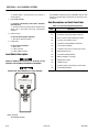
Service and Maintenance Manual
Model
E450A
E450AJ
M450A
M450AJ
P/N - 3121829
March 20, 2014
INTRODUCTION
SECTION A. INTRODUCTION - MAINTENANCE SAFETY PRECAUTIONS
A
GENERAL
C
MAINTENANCE
This section contains the general safety precautions
which must be observed during maintenance of the aerial
platform. It is of utmost importance that maintenance personnel pay strict attention to these warnings and precautions to avoid possible injury to themselves or others, or
damage to the equipment. A maintenance program must
be followed to ensure that the machine is safe to operate.
FAILURE TO COMPLY WITH SAFETY PRECAUTIONS LISTED IN
THIS SECTION COULD RESULT IN MACHINE DAMAGE, PERSONNEL INJURY OR DEATH AND IS A SAFETY VIOLATION.
MODIFICATION OR ALTERATION OF AN AERIAL WORK PLATFORM SHALL BE MADE ONLY WITH WRITTEN PERMISSION
FROM THE MANUFACTURER.
• NO SMOKING IS MANDATORY. NEVER REFUEL DURING ELECTRICAL STORMS. ENSURE THAT FUEL
CAP IS CLOSED AND SECURE AT ALL OTHER
TIMES.
The specific precautions to be observed during maintenance are inserted at the appropriate point in the manual.
These precautions are, for the most part, those that apply
when servicing hydraulic and larger machine component
parts.
• REMOVE ALL RINGS, WATCHES AND JEWELRY
WHEN PERFORMING ANY MAINTENANCE.
Your safety, and that of others, is the first consideration
when engaging in the maintenance of equipment. Always
be conscious of weight. Never attempt to move heavy
parts without the aid of a mechanical device. Do not allow
heavy objects to rest in an unstable position. When raising
a portion of the equipment, ensure that adequate support
is provided.
SINCE THE MACHINE MANUFACTURER HAS NO DIRECT CONTROL OVER THE FIELD INSPECTION AND MAINTENANCE,
SAFETY IN THIS AREA RESPONSIBILITY OF THE OWNER/OPERATOR.
B
HYDRAULIC SYSTEM SAFETY
It should be noted that the machines hydraulic systems
operate at extremely high potentially dangerous pressures. Every effort should be made to relieve any system
pressure prior to disconnecting or removing any portion of
the system.
• ENSURE REPLACEMENT PARTS OR COMPONENTS
ARE IDENTICAL OR EQUIVALENT TO ORIGINAL PARTS
OR COMPONENTS.
• DO NOT WEAR LONG HAIR UNRESTRAINED, OR
LOOSE-FITTING CLOTHING AND NECKTIES WHICH
ARE APT TO BECOME CAUGHT ON OR ENTANGLED
IN EQUIPMENT.
• OBSERVE AND OBEY ALL WARNINGS AND CAUTIONS ON MACHINE AND IN SERVICEMANUAL.
• KEEP OIL, GREASE, WATER, ETC. WIPED FROM
STANDING SURFACES AND HAND HOLDS.
• USE CAUTION WHEN CHECKING A HOT, PRESSURIZED COOLANT SYSTEM.
• NEVER WORK UNDER AN ELEVATED BOOM UNTIL
BOOM HAS BEEN SAFELY RESTRAINED FROM ANY
MOVEMENT BY BLOCKING OR OVERHEAD SLING,
OR BOOM SAFETY PROP HAS BEEN ENGAGED.
• BEFORE MAKING ADJUSTMENTS, LUBRICATING OR
PERFORMING ANY OTHER MAINTENANCE, SHUT
OFF ALL POWER CONTROLS.
• BATTERY SHOULD ALWAYS BE DISCONNECTEDDURING REPLACEMENT OF ELECTRICAL COMPONENTS.
• KEEP ALL SUPPORT EQUIPMENT AND ATTACHMENTS STOWED IN THEIR PROPER PLACE.
• USE ONLY APPROVED, NONFLAMMABLE CLEANING
SOLVENTS.
3121829
– JLG Lift –
A-1
INTRODUCTION
REVISON LOG
Original Issue
Revised
Revised
Revised
Revised
Revised
Revised
Revised
Revised
Revised
A-2
- August 15, 1999
- April 5, 2001
- May 25, 2004
- July 31, 2007
- January 25, 2008
- January 26, 2009
- November 27, 2012
- April 26, 2013
- October 24, 2013
- March 20, 2014
– JLG Lift –
3121829
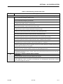
TABLE OF CONTENTS
SECTION NO.
TITLE
PAGE NO.
SECTION A - INTRODUCTION - MAINTENANCE SAFETY PRECAUTIONS
A
B
C
General . . . . . . . . . . . . . . . . . . . . . . . . . . . . . . . . . . . . . . . . . . . . . . . . . . . . . . . . . . . . . . . . . . . . . .A-1
Hydraulic System Safety . . . . . . . . . . . . . . . . . . . . . . . . . . . . . . . . . . . . . . . . . . . . . . . . . . . . . . . . .A-1
Maintenance . . . . . . . . . . . . . . . . . . . . . . . . . . . . . . . . . . . . . . . . . . . . . . . . . . . . . . . . . . . . . . . . . .A-1
SECTION 1 - SPECIFICATIONS
1.1
1.2
1.3
1.4
1.5
1.6
1.7
1.8
1.9
1.10
1.11
1.12
1.13
1.14
1.15
1.16
1.17
Operating specifications . . . . . . . . . . . . . . . . . . . . . . . . . . . . . . . . . . . . . . . . . . . . . . . . . . . . . . . . .1-1
Capacities . . . . . . . . . . . . . . . . . . . . . . . . . . . . . . . . . . . . . . . . . . . . . . . . . . . . . . . . . . . . . . . . . . . .1-1
Tires . . . . . . . . . . . . . . . . . . . . . . . . . . . . . . . . . . . . . . . . . . . . . . . . . . . . . . . . . . . . . . . . . . . . . . . . .1-1
Battery Charger . . . . . . . . . . . . . . . . . . . . . . . . . . . . . . . . . . . . . . . . . . . . . . . . . . . . . . . . . . . . . . . .1-1
Dimensional Data . . . . . . . . . . . . . . . . . . . . . . . . . . . . . . . . . . . . . . . . . . . . . . . . . . . . . . . . . . . . . .1-1
Drive System . . . . . . . . . . . . . . . . . . . . . . . . . . . . . . . . . . . . . . . . . . . . . . . . . . . . . . . . . . . . . . . . . .1-2
Hydraulic Pump/Electric Motor Assembly . . . . . . . . . . . . . . . . . . . . . . . . . . . . . . . . . . . . . . . . . . .1-2
Generator. . . . . . . . . . . . . . . . . . . . . . . . . . . . . . . . . . . . . . . . . . . . . . . . . . . . . . . . . . . . . . . . . . . . .1-2
Function Speeds . . . . . . . . . . . . . . . . . . . . . . . . . . . . . . . . . . . . . . . . . . . . . . . . . . . . . . . . . . . . . . .1-2
Pressure Settings . . . . . . . . . . . . . . . . . . . . . . . . . . . . . . . . . . . . . . . . . . . . . . . . . . . . . . . . . . . . . .1-3
Torque Specifications . . . . . . . . . . . . . . . . . . . . . . . . . . . . . . . . . . . . . . . . . . . . . . . . . . . . . . . . . . .1-4
Lubrication Specifications . . . . . . . . . . . . . . . . . . . . . . . . . . . . . . . . . . . . . . . . . . . . . . . . . . . . . . . .1-4
Hydraulic Oil . . . . . . . . . . . . . . . . . . . . . . . . . . . . . . . . . . . . . . . . . . . . . . . . . . . . . . . . . . . . . 1-4
Critical Stability Weights . . . . . . . . . . . . . . . . . . . . . . . . . . . . . . . . . . . . . . . . . . . . . . . . . . . . . . . . .1-4
Cylinder Specifications . . . . . . . . . . . . . . . . . . . . . . . . . . . . . . . . . . . . . . . . . . . . . . . . . . . . . . . . . .1-5
Major Component Weights . . . . . . . . . . . . . . . . . . . . . . . . . . . . . . . . . . . . . . . . . . . . . . . . . . . . . . .1-5
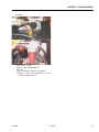
Serial Number Locations. . . . . . . . . . . . . . . . . . . . . . . . . . . . . . . . . . . . . . . . . . . . . . . . . . . . . . . . .1-5
Operator Maintenance & Lubrication . . . . . . . . . . . . . . . . . . . . . . . . . . . . . . . . . . . . . . . . . . . . . . .1-7
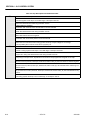
SECTION 2 - GENERAL
2.1
2.2
3121829
Machine Preparation, Inspection, and Maintenance . . . . . . . . . . . . . . . . . . . . . . . . . . . . . . . . . . .2-1
General. . . . . . . . . . . . . . . . . . . . . . . . . . . . . . . . . . . . . . . . . . . . . . . . . . . . . . . . . . . . . . . . . . 2-1
Preparation, Inspection, and Maintenance . . . . . . . . . . . . . . . . . . . . . . . . . . . . . . . . . . . . . . 2-1
Pre-Start Inspection . . . . . . . . . . . . . . . . . . . . . . . . . . . . . . . . . . . . . . . . . . . . . . . . . . . . . . . . 2-1
Pre-Delivery Inspection and Frequent Inspection . . . . . . . . . . . . . . . . . . . . . . . . . . . . . . . . . 2-1
Annual Machine Inspection . . . . . . . . . . . . . . . . . . . . . . . . . . . . . . . . . . . . . . . . . . . . . . . . . . 2-1
Preventive Maintenance. . . . . . . . . . . . . . . . . . . . . . . . . . . . . . . . . . . . . . . . . . . . . . . . . . . . . 2-1
Service and Guidelines . . . . . . . . . . . . . . . . . . . . . . . . . . . . . . . . . . . . . . . . . . . . . . . . . . . . . . . . . .2-2
General. . . . . . . . . . . . . . . . . . . . . . . . . . . . . . . . . . . . . . . . . . . . . . . . . . . . . . . . . . . . . . . . . . 2-2
Safety and Workmanship . . . . . . . . . . . . . . . . . . . . . . . . . . . . . . . . . . . . . . . . . . . . . . . . . . . 2-2
Cleanliness. . . . . . . . . . . . . . . . . . . . . . . . . . . . . . . . . . . . . . . . . . . . . . . . . . . . . . . . . . . . . . . 2-2
Components Removal and Installation . . . . . . . . . . . . . . . . . . . . . . . . . . . . . . . . . . . . . . . . . 2-2
Component Disassembly and Reassembly . . . . . . . . . . . . . . . . . . . . . . . . . . . . . . . . . . . . . 2-3
Pressure-Fit Parts. . . . . . . . . . . . . . . . . . . . . . . . . . . . . . . . . . . . . . . . . . . . . . . . . . . . . . . . . . 2-3
Bearings . . . . . . . . . . . . . . . . . . . . . . . . . . . . . . . . . . . . . . . . . . . . . . . . . . . . . . . . . . . . . . . . . 2-3
Gaskets . . . . . . . . . . . . . . . . . . . . . . . . . . . . . . . . . . . . . . . . . . . . . . . . . . . . . . . . . . . . . . . . . 2-3
Bolt Usage and Torque Application . . . . . . . . . . . . . . . . . . . . . . . . . . . . . . . . . . . . . . . . . . . 2-3
Hydraulic Lines and Electrical Wiring . . . . . . . . . . . . . . . . . . . . . . . . . . . . . . . . . . . . . . . . . . 2-3
Hydraulic System. . . . . . . . . . . . . . . . . . . . . . . . . . . . . . . . . . . . . . . . . . . . . . . . . . . . . . . . . . 2-3
Lubrication . . . . . . . . . . . . . . . . . . . . . . . . . . . . . . . . . . . . . . . . . . . . . . . . . . . . . . . . . . . . . . . 2-3
Battery . . . . . . . . . . . . . . . . . . . . . . . . . . . . . . . . . . . . . . . . . . . . . . . . . . . . . . . . . . . . . . . . . . 2-3
Lubrication and Servicing . . . . . . . . . . . . . . . . . . . . . . . . . . . . . . . . . . . . . . . . . . . . . . . . . . . 2-3
– JLG Lift –
i
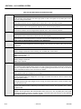
TABLE OF CONTENTS
SECTION NO.
2.3
2.4
2.5
2.6
TITLE
PAGE NO.
Lubrication and Information . . . . . . . . . . . . . . . . . . . . . . . . . . . . . . . . . . . . . . . . . . . . . . . . . . . . . .2-3
Hydraulic System. . . . . . . . . . . . . . . . . . . . . . . . . . . . . . . . . . . . . . . . . . . . . . . . . . . . . . . . . . 2-3
Hydraulic Oil . . . . . . . . . . . . . . . . . . . . . . . . . . . . . . . . . . . . . . . . . . . . . . . . . . . . . . . . . . . . . 2-4
Changing Hydraulic Oil . . . . . . . . . . . . . . . . . . . . . . . . . . . . . . . . . . . . . . . . . . . . . . . . . . . . . 2-4
Lubrication Specifications . . . . . . . . . . . . . . . . . . . . . . . . . . . . . . . . . . . . . . . . . . . . . . . . . . . 2-4
Cylinder Drift Test . . . . . . . . . . . . . . . . . . . . . . . . . . . . . . . . . . . . . . . . . . . . . . . . . . . . . . . . . . . . . .2-4
Platform Drift . . . . . . . . . . . . . . . . . . . . . . . . . . . . . . . . . . . . . . . . . . . . . . . . . . . . . . . . . . . . . 2-4
Cylinder Drift . . . . . . . . . . . . . . . . . . . . . . . . . . . . . . . . . . . . . . . . . . . . . . . . . . . . . . . . . . . . . 2-4
Pins and Composite Bearing Repair Guidelines . . . . . . . . . . . . . . . . . . . . . . . . . . . . . . . . . . . . . .2-5
Welding on JLG Equipment . . . . . . . . . . . . . . . . . . . . . . . . . . . . . . . . . . . . . . . . . . . . . . . . . . . . . .2-5
Do the Following When Welding on JLG Equipment . . . . . . . . . . . . . . . . . . . . . . . . . . . . . . 2-5
Do NOT Do the Following When Welding on JLG Equipment . . . . . . . . . . . . . . . . . . . . . . . 2-5
SECTION 3 - CHASSIS & TURNTABLE
3.1
3.2
3.3
3.4
3.5
3.6
3.7
ii
Tires & Wheels. . . . . . . . . . . . . . . . . . . . . . . . . . . . . . . . . . . . . . . . . . . . . . . . . . . . . . . . . . . . . . . . .3-1
Tire Inflation . . . . . . . . . . . . . . . . . . . . . . . . . . . . . . . . . . . . . . . . . . . . . . . . . . . . . . . . . . . . . . 3-1
Tire Damage . . . . . . . . . . . . . . . . . . . . . . . . . . . . . . . . . . . . . . . . . . . . . . . . . . . . . . . . . . . . . 3-1
Tire Replacement. . . . . . . . . . . . . . . . . . . . . . . . . . . . . . . . . . . . . . . . . . . . . . . . . . . . . . . . . . 3-1
Wheel Replacement. . . . . . . . . . . . . . . . . . . . . . . . . . . . . . . . . . . . . . . . . . . . . . . . . . . . . . . . 3-1
Wheel Installation. . . . . . . . . . . . . . . . . . . . . . . . . . . . . . . . . . . . . . . . . . . . . . . . . . . . . . . . . . 3-1
Spindle. . . . . . . . . . . . . . . . . . . . . . . . . . . . . . . . . . . . . . . . . . . . . . . . . . . . . . . . . . . . . . . . . . . . . . .3-2
Setting Wheel Bearing End Play . . . . . . . . . . . . . . . . . . . . . . . . . . . . . . . . . . . . . . . . . . . . . . 3-2
Specifications. . . . . . . . . . . . . . . . . . . . . . . . . . . . . . . . . . . . . . . . . . . . . . . . . . . . . . . . . . . . . 3-2
Checking . . . . . . . . . . . . . . . . . . . . . . . . . . . . . . . . . . . . . . . . . . . . . . . . . . . . . . . . . . . . . . . . 3-2
Greasing Requirements. . . . . . . . . . . . . . . . . . . . . . . . . . . . . . . . . . . . . . . . . . . . . . . . . . . . . 3-2
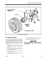
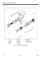
Drive Hub
Part No. 27802363-4
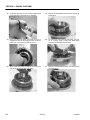
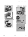
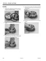
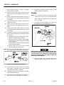
Disassembly. . . . . . . . . . . . . . . . . . . . . . . . . . . . . . . . . . . . . . . . . . . . . . . . . . . . . . . . . . . . . . 3-4
Disassembly of Cover . . . . . . . . . . . . . . . . . . . . . . . . . . . . . . . . . . . . . . . . . . . . . . . . . . . . . . 3-5
Disassembly of First Stage Planetary Assembly (7) . . . . . . . . . . . . . . . . . . . . . . . . . . . . . . . 3-5
Disassembly of Second Stage Planet Gears (1). . . . . . . . . . . . . . . . . . . . . . . . . . . . . . . . . . 3-5
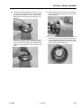
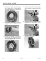
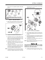
Assembly of First Stage Planetary Assembly (7) . . . . . . . . . . . . . . . . . . . . . . . . . . . . . . . . . 3-5
Assembly of End Cover Unit (8) . . . . . . . . . . . . . . . . . . . . . . . . . . . . . . . . . . . . . . . . . . . . . . 3-5
Final Assembly. . . . . . . . . . . . . . . . . . . . . . . . . . . . . . . . . . . . . . . . . . . . . . . . . . . . . . . . . . . . 3-6
Initial Start-up and After Repairs . . . . . . . . . . . . . . . . . . . . . . . . . . . . . . . . . . . . . . . . . . . . . . 3-6
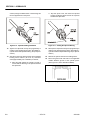
Maintenance . . . . . . . . . . . . . . . . . . . . . . . . . . . . . . . . . . . . . . . . . . . . . . . . . . . . . . . . . . . . . 3-6
Oil Change Interval-Gear Drive . . . . . . . . . . . . . . . . . . . . . . . . . . . . . . . . . . . . . . . . . . . . . . . 3-6
Setting of Tapered Roller Bearings . . . . . . . . . . . . . . . . . . . . . . . . . . . . . . . . . . . . . . . . . . . . 3-6
Securing of the Shaft Nut . . . . . . . . . . . . . . . . . . . . . . . . . . . . . . . . . . . . . . . . . . . . . . . . . . . 3-6
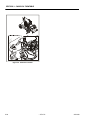
Drive Brake - Mico . . . . . . . . . . . . . . . . . . . . . . . . . . . . . . . . . . . . . . . . . . . . . . . . . . . . . . . . . . . . . .3-8
Disassembly. . . . . . . . . . . . . . . . . . . . . . . . . . . . . . . . . . . . . . . . . . . . . . . . . . . . . . . . . . . . . . 3-8
Assembly . . . . . . . . . . . . . . . . . . . . . . . . . . . . . . . . . . . . . . . . . . . . . . . . . . . . . . . . . . . . . . . . 3-8
Bleeding . . . . . . . . . . . . . . . . . . . . . . . . . . . . . . . . . . . . . . . . . . . . . . . . . . . . . . . . . . . . . . . . . 3-8
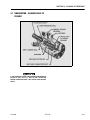
Speed Sensor Adjustment . . . . . . . . . . . . . . . . . . . . . . . . . . . . . . . . . . . . . . . . . . . . . . . . . . . . . . .3-11
Adjustment Procedure. . . . . . . . . . . . . . . . . . . . . . . . . . . . . . . . . . . . . . . . . . . . . . . . . . . . . . 3-11
Speed Sensor Installation Verification. . . . . . . . . . . . . . . . . . . . . . . . . . . . . . . . . . . . . . . . . . 3-16
Verification w/ Analyzer Procedure . . . . . . . . . . . . . . . . . . . . . . . . . . . . . . . . . . . . . . . . . . . . 3-16
Positrac/Tilt module. . . . . . . . . . . . . . . . . . . . . . . . . . . . . . . . . . . . . . . . . . . . . . . . . . . . . . . . . . . . .3-19
Swing Motor - S/N 0300135649 to Present. . . . . . . . . . . . . . . . . . . . . . . . . . . . . . . . . . . . . . . . . . .3-21
Preparation Before Disassembly . . . . . . . . . . . . . . . . . . . . . . . . . . . . . . . . . . . . . . . . . . . . . . 3-24
Disassembly and Inspection . . . . . . . . . . . . . . . . . . . . . . . . . . . . . . . . . . . . . . . . . . . . . . . . . 3-24
Assembly . . . . . . . . . . . . . . . . . . . . . . . . . . . . . . . . . . . . . . . . . . . . . . . . . . . . . . . . . . . . . . . . 3-30
One Piece Stator Construction . . . . . . . . . . . . . . . . . . . . . . . . . . . . . . . . . . . . . . . . . . . . . . . 3-37
Two Piece Stator Construction . . . . . . . . . . . . . . . . . . . . . . . . . . . . . . . . . . . . . . . . . . . . . . . 3-38
Final Checks . . . . . . . . . . . . . . . . . . . . . . . . . . . . . . . . . . . . . . . . . . . . . . . . . . . . . . . . . . . . . 3-38
– JLG Lift –
3121829
TABLE OF CONTENTS
SECTION NO.
3.8
3.9
3.10
3.12
3.13
3121829
TITLE
PAGE NO.
Swing Bearing . . . . . . . . . . . . . . . . . . . . . . . . . . . . . . . . . . . . . . . . . . . . . . . . . . . . . . . . . . . . . . . . .3-39
Turntable Bearing Mounting Bolt Condition Check . . . . . . . . . . . . . . . . . . . . . . . . . . . . . . . 3-39
Wear Tolerance . . . . . . . . . . . . . . . . . . . . . . . . . . . . . . . . . . . . . . . . . . . . . . . . . . . . . . . . . . . 3-40
Replacement of Swing Bearing . . . . . . . . . . . . . . . . . . . . . . . . . . . . . . . . . . . . . . . . . . . . . . . 3-41
Swing Bearing Torque Value . . . . . . . . . . . . . . . . . . . . . . . . . . . . . . . . . . . . . . . . . . . . . . . . . 3-43
Checking Worm Gear End Play. . . . . . . . . . . . . . . . . . . . . . . . . . . . . . . . . . . . . . . . . . . . . . . 3-43
Adjusting End Play. . . . . . . . . . . . . . . . . . . . . . . . . . . . . . . . . . . . . . . . . . . . . . . . . . . . . . . . . 3-43
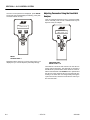
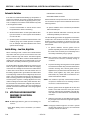
Battery Maintenance and Charging . . . . . . . . . . . . . . . . . . . . . . . . . . . . . . . . . . . . . . . . . . . . . . . .3-45
Battery Maintenance, Quarterly . . . . . . . . . . . . . . . . . . . . . . . . . . . . . . . . . . . . . . . . . . . . . . . 3-45
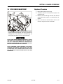
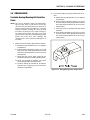
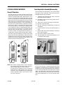
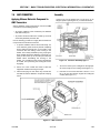
Optional On Board Generator . . . . . . . . . . . . . . . . . . . . . . . . . . . . . . . . . . . . . . . . . . . . . . . . 3-45
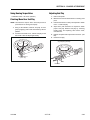
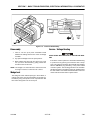
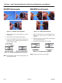
Battery Charging (On Board Charger) . . . . . . . . . . . . . . . . . . . . . . . . . . . . . . . . . . . . . . . . . 3-47
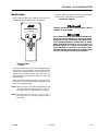
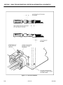
Battery Charger (S/N 0300059350 to Present) . . . . . . . . . . . . . . . . . . . . . . . . . . . . . . . . . . . . . . . .3-48
Operating Instructions . . . . . . . . . . . . . . . . . . . . . . . . . . . . . . . . . . . . . . . . . . . . . . . . . . . . . . 3-48
Maintenance Instructions. . . . . . . . . . . . . . . . . . . . . . . . . . . . . . . . . . . . . . . . . . . . . . . . . . . . 3-48
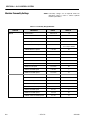
Battery Charger Fault Codes . . . . . . . . . . . . . . . . . . . . . . . . . . . . . . . . . . . . . . . . . . . . . . . . . 3-48
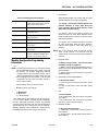
Excessive Battery Watering Requirements or Strong Sulphur (Rotten Egg) Smell . . . . . . . 3-51
Checking/Changing the Battery Charger Algorithm . . . . . . . . . . . . . . . . . . . . . . . . . . . . . . . 3-52
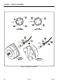
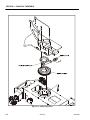
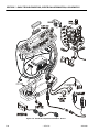
Generator (Prior to S/N 88539) . . . . . . . . . . . . . . . . . . . . . . . . . . . . . . . . . . . . . . . . . . . . . . . . . . . .3-53
Timing Sequences . . . . . . . . . . . . . . . . . . . . . . . . . . . . . . . . . . . . . . . . . . . . . . . . . . . . . . . . . 3-55
To Connect the JLG Control System Analyzer to the Generator . . . . . . . . . . . . . . . . . . . . . 3-56
Alarms and Fault Flash Codes . . . . . . . . . . . . . . . . . . . . . . . . . . . . . . . . . . . . . . . . . . . . . . . 3-56
Output Current and Voltage Settings . . . . . . . . . . . . . . . . . . . . . . . . . . . . . . . . . . . . . . . . . . 3-58
Priming the Fuel Line . . . . . . . . . . . . . . . . . . . . . . . . . . . . . . . . . . . . . . . . . . . . . . . . . . . . . . . 3-59
Generator (S/N 88539 to Present) . . . . . . . . . . . . . . . . . . . . . . . . . . . . . . . . . . . . . . . . . . . . . . . . .3-60
Engine . . . . . . . . . . . . . . . . . . . . . . . . . . . . . . . . . . . . . . . . . . . . . . . . . . . . . . . . . . . . . . . . . . 3-60
Alternator . . . . . . . . . . . . . . . . . . . . . . . . . . . . . . . . . . . . . . . . . . . . . . . . . . . . . . . . . . . . . . . . 3-60
Dynamo and Dynamo Voltage Regulator . . . . . . . . . . . . . . . . . . . . . . . . . . . . . . . . . . . . . . . 3-60
Dynamo Output Fuse . . . . . . . . . . . . . . . . . . . . . . . . . . . . . . . . . . . . . . . . . . . . . . . . . . . . . . 3-60
Control Fuse . . . . . . . . . . . . . . . . . . . . . . . . . . . . . . . . . . . . . . . . . . . . . . . . . . . . . . . . . . . . . 3-60
Start Battery . . . . . . . . . . . . . . . . . . . . . . . . . . . . . . . . . . . . . . . . . . . . . . . . . . . . . . . . . . . . . . 3-62
Engine Starter . . . . . . . . . . . . . . . . . . . . . . . . . . . . . . . . . . . . . . . . . . . . . . . . . . . . . . . . . . . . 3-62
Start Control Relay. . . . . . . . . . . . . . . . . . . . . . . . . . . . . . . . . . . . . . . . . . . . . . . . . . . . . . . . . 3-62
Fuel Control Relay . . . . . . . . . . . . . . . . . . . . . . . . . . . . . . . . . . . . . . . . . . . . . . . . . . . . . . . . . 3-63
Glow Plug Control Relay . . . . . . . . . . . . . . . . . . . . . . . . . . . . . . . . . . . . . . . . . . . . . . . . . . . . 3-63
Glow Plug. . . . . . . . . . . . . . . . . . . . . . . . . . . . . . . . . . . . . . . . . . . . . . . . . . . . . . . . . . . . . . . . 3-63
Fuel Pump . . . . . . . . . . . . . . . . . . . . . . . . . . . . . . . . . . . . . . . . . . . . . . . . . . . . . . . . . . . . . . . 3-64
Fuel Solenoid . . . . . . . . . . . . . . . . . . . . . . . . . . . . . . . . . . . . . . . . . . . . . . . . . . . . . . . . . . . . . 3-64
Engine Low Oil Pressure Switch . . . . . . . . . . . . . . . . . . . . . . . . . . . . . . . . . . . . . . . . . . . . . . 3-64
Engine Oil Temperature Sensor . . . . . . . . . . . . . . . . . . . . . . . . . . . . . . . . . . . . . . . . . . . . . . 3-64
Alternator Output Current Sensor . . . . . . . . . . . . . . . . . . . . . . . . . . . . . . . . . . . . . . . . . . . . . 3-65
Engine Speed Sensor . . . . . . . . . . . . . . . . . . . . . . . . . . . . . . . . . . . . . . . . . . . . . . . . . . . . . . 3-65
RBS Engine/Generator Controller . . . . . . . . . . . . . . . . . . . . . . . . . . . . . . . . . . . . . . . . . . . . . 3-65
Warnings and Safety Precautions . . . . . . . . . . . . . . . . . . . . . . . . . . . . . . . . . . . . . . . . . . . . . 3-66
System Controls . . . . . . . . . . . . . . . . . . . . . . . . . . . . . . . . . . . . . . . . . . . . . . . . . . . . . . . . . . 3-66
System Status and Performance Monitoring . . . . . . . . . . . . . . . . . . . . . . . . . . . . . . . . . . . . 3-66
System Settings . . . . . . . . . . . . . . . . . . . . . . . . . . . . . . . . . . . . . . . . . . . . . . . . . . . . . . . . . . . 3-66
RBS Start . . . . . . . . . . . . . . . . . . . . . . . . . . . . . . . . . . . . . . . . . . . . . . . . . . . . . . . . . . . . . . . . 3-67
RBS shutdown . . . . . . . . . . . . . . . . . . . . . . . . . . . . . . . . . . . . . . . . . . . . . . . . . . . . . . . . . . . . 3-67
RBS Alarms and Flash Codes . . . . . . . . . . . . . . . . . . . . . . . . . . . . . . . . . . . . . . . . . . . . . . . . 3-68
Resetting the RBS Controller. . . . . . . . . . . . . . . . . . . . . . . . . . . . . . . . . . . . . . . . . . . . . . . . . 3-68
Maintenance Schedule . . . . . . . . . . . . . . . . . . . . . . . . . . . . . . . . . . . . . . . . . . . . . . . . . . . . . 3-68
Troubleshooting. . . . . . . . . . . . . . . . . . . . . . . . . . . . . . . . . . . . . . . . . . . . . . . . . . . . . . . . . . . 3-69
APU Engine Start Battery Boosting . . . . . . . . . . . . . . . . . . . . . . . . . . . . . . . . . . . . . . . . . . . . 3-70
– JLG Lift –
iii
TABLE OF CONTENTS
SECTION NO.
3.14
TITLE
PAGE NO.
Supplementary fuse for apu . . . . . . . . . . . . . . . . . . . . . . . . . . . . . . . . . . . . . . . . . . . . . . . . . . . . . .3-71
Tools And Material . . . . . . . . . . . . . . . . . . . . . . . . . . . . . . . . . . . . . . . . . . . . . . . . . . . . . . . . . 3-71
Procedure . . . . . . . . . . . . . . . . . . . . . . . . . . . . . . . . . . . . . . . . . . . . . . . . . . . . . . . . . . . . . . . 3-71
SECTION 4 - BOOM & PLATFORM
4.1
4.2
4.3
4.4
4.5
4.6
4.7
4.8
4.9
4.10
4.11
4.12
4.13
iv
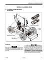
Boom Maintenance . . . . . . . . . . . . . . . . . . . . . . . . . . . . . . . . . . . . . . . . . . . . . . . . . . . . . . . . . . . . .4-1
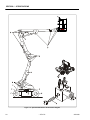
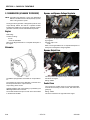
Removal . . . . . . . . . . . . . . . . . . . . . . . . . . . . . . . . . . . . . . . . . . . . . . . . . . . . . . . . . . . . . . . . . 4-1
Disassembly Boom Sections. . . . . . . . . . . . . . . . . . . . . . . . . . . . . . . . . . . . . . . . . . . . . . . . . 4-1
Inspection . . . . . . . . . . . . . . . . . . . . . . . . . . . . . . . . . . . . . . . . . . . . . . . . . . . . . . . . . . . . . . . 4-2
Assembly . . . . . . . . . . . . . . . . . . . . . . . . . . . . . . . . . . . . . . . . . . . . . . . . . . . . . . . . . . . . . . . . 4-2
Installation . . . . . . . . . . . . . . . . . . . . . . . . . . . . . . . . . . . . . . . . . . . . . . . . . . . . . . . . . . . . . . . 4-3
Upper (Main) Boom Lift Cylinder . . . . . . . . . . . . . . . . . . . . . . . . . . . . . . . . . . . . . . . . . . . . . . . . . .4-4
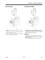
Removal . . . . . . . . . . . . . . . . . . . . . . . . . . . . . . . . . . . . . . . . . . . . . . . . . . . . . . . . . . . . . . . . . 4-4
Installation . . . . . . . . . . . . . . . . . . . . . . . . . . . . . . . . . . . . . . . . . . . . . . . . . . . . . . . . . . . . . . . 4-4
Mid Boom Lift Cylinder . . . . . . . . . . . . . . . . . . . . . . . . . . . . . . . . . . . . . . . . . . . . . . . . . . . . . . . . . .4-4
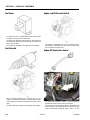
Removal . . . . . . . . . . . . . . . . . . . . . . . . . . . . . . . . . . . . . . . . . . . . . . . . . . . . . . . . . . . . . . . . . 4-4
Installation . . . . . . . . . . . . . . . . . . . . . . . . . . . . . . . . . . . . . . . . . . . . . . . . . . . . . . . . . . . . . . . 4-5
Lower Boom Lift Cylinder . . . . . . . . . . . . . . . . . . . . . . . . . . . . . . . . . . . . . . . . . . . . . . . . . . . . . . . .4-5
Removal . . . . . . . . . . . . . . . . . . . . . . . . . . . . . . . . . . . . . . . . . . . . . . . . . . . . . . . . . . . . . . . . . 4-5
Installation . . . . . . . . . . . . . . . . . . . . . . . . . . . . . . . . . . . . . . . . . . . . . . . . . . . . . . . . . . . . . . . 4-5
Upper Boom Telescope Cylinder . . . . . . . . . . . . . . . . . . . . . . . . . . . . . . . . . . . . . . . . . . . . . . . . . .4-6
Removal . . . . . . . . . . . . . . . . . . . . . . . . . . . . . . . . . . . . . . . . . . . . . . . . . . . . . . . . . . . . . . . . . 4-6
Installation . . . . . . . . . . . . . . . . . . . . . . . . . . . . . . . . . . . . . . . . . . . . . . . . . . . . . . . . . . . . . . . 4-6
Wear Pads . . . . . . . . . . . . . . . . . . . . . . . . . . . . . . . . . . . . . . . . . . . . . . . . . . . . . . . . . . . . . . . . . . . .4-7
Boom Limit Switches. . . . . . . . . . . . . . . . . . . . . . . . . . . . . . . . . . . . . . . . . . . . . . . . . . . . . . . . . . . .4-7
Articulating Jib Boom . . . . . . . . . . . . . . . . . . . . . . . . . . . . . . . . . . . . . . . . . . . . . . . . . . . . . . . . . . .4-11
Removal . . . . . . . . . . . . . . . . . . . . . . . . . . . . . . . . . . . . . . . . . . . . . . . . . . . . . . . . . . . . . . . . . 4-11
Disassembly. . . . . . . . . . . . . . . . . . . . . . . . . . . . . . . . . . . . . . . . . . . . . . . . . . . . . . . . . . . . . . 4-11
Inspection . . . . . . . . . . . . . . . . . . . . . . . . . . . . . . . . . . . . . . . . . . . . . . . . . . . . . . . . . . . . . . . 4-11
Assembly . . . . . . . . . . . . . . . . . . . . . . . . . . . . . . . . . . . . . . . . . . . . . . . . . . . . . . . . . . . . . . . . 4-11
Load Sensing System . . . . . . . . . . . . . . . . . . . . . . . . . . . . . . . . . . . . . . . . . . . . . . . . . . . . . . . . . . .4-12
Calibration . . . . . . . . . . . . . . . . . . . . . . . . . . . . . . . . . . . . . . . . . . . . . . . . . . . . . . . . . . . . . . . 4-12
Boom Synchronizing Procedure. . . . . . . . . . . . . . . . . . . . . . . . . . . . . . . . . . . . . . . . . . . . . . . . . . .4-12
Footswitch Adjustment . . . . . . . . . . . . . . . . . . . . . . . . . . . . . . . . . . . . . . . . . . . . . . . . . . . . . . . . . .4-12
Helac Rotary actuator . . . . . . . . . . . . . . . . . . . . . . . . . . . . . . . . . . . . . . . . . . . . . . . . . . . . . . . . . . .4-13
Theory Of Operation . . . . . . . . . . . . . . . . . . . . . . . . . . . . . . . . . . . . . . . . . . . . . . . . . . . . . . . 4-13
Tools Required for Assembly/Disassembly . . . . . . . . . . . . . . . . . . . . . . . . . . . . . . . . . . . . . 4-13
Disassembly. . . . . . . . . . . . . . . . . . . . . . . . . . . . . . . . . . . . . . . . . . . . . . . . . . . . . . . . . . . . . . 4-16
Inspection . . . . . . . . . . . . . . . . . . . . . . . . . . . . . . . . . . . . . . . . . . . . . . . . . . . . . . . . . . . . . . . 4-19
Assembly . . . . . . . . . . . . . . . . . . . . . . . . . . . . . . . . . . . . . . . . . . . . . . . . . . . . . . . . . . . . . . . . 4-20
Installing Counterbalance Valve . . . . . . . . . . . . . . . . . . . . . . . . . . . . . . . . . . . . . . . . . . . . . . 4-24
Testing the Actuator. . . . . . . . . . . . . . . . . . . . . . . . . . . . . . . . . . . . . . . . . . . . . . . . . . . . . . . . 4-24
Installation and Bleeding . . . . . . . . . . . . . . . . . . . . . . . . . . . . . . . . . . . . . . . . . . . . . . . . . . . . 4-26
Troubleshooting. . . . . . . . . . . . . . . . . . . . . . . . . . . . . . . . . . . . . . . . . . . . . . . . . . . . . . . . . . . 4-27
Powertrack Maintenance. . . . . . . . . . . . . . . . . . . . . . . . . . . . . . . . . . . . . . . . . . . . . . . . . . . . . . . . .4-28
Removing a Link . . . . . . . . . . . . . . . . . . . . . . . . . . . . . . . . . . . . . . . . . . . . . . . . . . . . . . . . . . 4-28
Installing a New Link . . . . . . . . . . . . . . . . . . . . . . . . . . . . . . . . . . . . . . . . . . . . . . . . . . . . . . . 4-31
Replacing Fixed End Brackets . . . . . . . . . . . . . . . . . . . . . . . . . . . . . . . . . . . . . . . . . . . . . . . 4-36
Replacing Moving End Brackets . . . . . . . . . . . . . . . . . . . . . . . . . . . . . . . . . . . . . . . . . . . . . . 4-38
– JLG Lift –
3121829
TABLE OF CONTENTS
SECTION NO.
TITLE
PAGE NO.
SECTION 5 - HYDRAULICS
5.1
5.2
5.3
5.4
5.5
Lubricating O-Rings in the Hydraulic System . . . . . . . . . . . . . . . . . . . . . . . . . . . . . . . . . . . . . . . . .5-1
Cup and Brush. . . . . . . . . . . . . . . . . . . . . . . . . . . . . . . . . . . . . . . . . . . . . . . . . . . . . . . . . . . . 5-1
Dip Method . . . . . . . . . . . . . . . . . . . . . . . . . . . . . . . . . . . . . . . . . . . . . . . . . . . . . . . . . . . . . . 5-2
Spray Method . . . . . . . . . . . . . . . . . . . . . . . . . . . . . . . . . . . . . . . . . . . . . . . . . . . . . . . . . . . . 5-2
Brush-on Method . . . . . . . . . . . . . . . . . . . . . . . . . . . . . . . . . . . . . . . . . . . . . . . . . . . . . . . . . . 5-2
Cylinders - Theory of Operation . . . . . . . . . . . . . . . . . . . . . . . . . . . . . . . . . . . . . . . . . . . . . . . . . . .5-3
Double Acting Cylinder . . . . . . . . . . . . . . . . . . . . . . . . . . . . . . . . . . . . . . . . . . . . . . . . . . . . . 5-3
Cylinder Checking Procedures . . . . . . . . . . . . . . . . . . . . . . . . . . . . . . . . . . . . . . . . . . . . . . . . . . . .5-3
Cylinder Without Counterbalance Valves . . . . . . . . . . . . . . . . . . . . . . . . . . . . . . . . . . . . . . . 5-3
Cylinders With Single Counterbalance Valve . . . . . . . . . . . . . . . . . . . . . . . . . . . . . . . . . . . . 5-3
Cylinders With Dual Counterbalance Valve. . . . . . . . . . . . . . . . . . . . . . . . . . . . . . . . . . . . . . 5-4
Cylinder Repair . . . . . . . . . . . . . . . . . . . . . . . . . . . . . . . . . . . . . . . . . . . . . . . . . . . . . . . . . . . . . . . .5-4
Disassembly. . . . . . . . . . . . . . . . . . . . . . . . . . . . . . . . . . . . . . . . . . . . . . . . . . . . . . . . . . . . . . 5-4
Cleaning and Inspection . . . . . . . . . . . . . . . . . . . . . . . . . . . . . . . . . . . . . . . . . . . . . . . . . . . . 5-5
Assembly . . . . . . . . . . . . . . . . . . . . . . . . . . . . . . . . . . . . . . . . . . . . . . . . . . . . . . . . . . . . . . . . 5-6
Pressure Setting Procedures . . . . . . . . . . . . . . . . . . . . . . . . . . . . . . . . . . . . . . . . . . . . . . . . . . . . .5-20
Main Relief . . . . . . . . . . . . . . . . . . . . . . . . . . . . . . . . . . . . . . . . . . . . . . . . . . . . . . . . . . . . . . . 5-20
Upper Lift Down Relief . . . . . . . . . . . . . . . . . . . . . . . . . . . . . . . . . . . . . . . . . . . . . . . . . . . . . . 5-20
Lower Lift Down Relief . . . . . . . . . . . . . . . . . . . . . . . . . . . . . . . . . . . . . . . . . . . . . . . . . . . . . . 5-20
Telescope Relief . . . . . . . . . . . . . . . . . . . . . . . . . . . . . . . . . . . . . . . . . . . . . . . . . . . . . . . . . . 5-20
Platform Level Up Relief. . . . . . . . . . . . . . . . . . . . . . . . . . . . . . . . . . . . . . . . . . . . . . . . . . . . . 5-20
Platform Level Down Relief . . . . . . . . . . . . . . . . . . . . . . . . . . . . . . . . . . . . . . . . . . . . . . . . . . 5-21
Steer Relief. . . . . . . . . . . . . . . . . . . . . . . . . . . . . . . . . . . . . . . . . . . . . . . . . . . . . . . . . . . . . . . 5-21
Jib Lift (Up and Down) Relief . . . . . . . . . . . . . . . . . . . . . . . . . . . . . . . . . . . . . . . . . . . . . . . . . 5-21
Releveling Valve Relief. . . . . . . . . . . . . . . . . . . . . . . . . . . . . . . . . . . . . . . . . . . . . . . . . . . . . . 5-21
SECTION 6 - JLG CONTROL SYSTEM
6.1
3121829
JLG Control System Analyzer Kit Instructions . . . . . . . . . . . . . . . . . . . . . . . . . . . . . . . . . . . . . . . .6-1
Introduction . . . . . . . . . . . . . . . . . . . . . . . . . . . . . . . . . . . . . . . . . . . . . . . . . . . . . . . . . . . . . . 6-1
To Connect the JLG Control System Analyzer . . . . . . . . . . . . . . . . . . . . . . . . . . . . . . . . . . . 6-2
Using the Analyzer. . . . . . . . . . . . . . . . . . . . . . . . . . . . . . . . . . . . . . . . . . . . . . . . . . . . . . . . . 6-2
Changing the Access Level of the Hand Held Analyzer . . . . . . . . . . . . . . . . . . . . . . . . . . . . 6-3
Adjusting Parameters Using the Hand Held Analyzer . . . . . . . . . . . . . . . . . . . . . . . . . . . . . 6-4
Machine Setup . . . . . . . . . . . . . . . . . . . . . . . . . . . . . . . . . . . . . . . . . . . . . . . . . . . . . . . . . . . . 6-5
Machine Personality Settings . . . . . . . . . . . . . . . . . . . . . . . . . . . . . . . . . . . . . . . . . . . . . . . . 6-6
Machine Configuration Programming Information . . . . . . . . . . . . . . . . . . . . . . . . . . . . . . . . 6-9
Level Vehicle Description. . . . . . . . . . . . . . . . . . . . . . . . . . . . . . . . . . . . . . . . . . . . . . . . . . . . 6-10
Help Descriptions and Fault Flash Codes. . . . . . . . . . . . . . . . . . . . . . . . . . . . . . . . . . . . . . . 6-10
Analyzer Diagnostics Menu Structure . . . . . . . . . . . . . . . . . . . . . . . . . . . . . . . . . . . . . . . . . . 6-20
System Self Test . . . . . . . . . . . . . . . . . . . . . . . . . . . . . . . . . . . . . . . . . . . . . . . . . . . . . . . . . . 6-22
– JLG Lift –
v
TABLE OF CONTENTS
SECTION NO.
TITLE
PAGE NO.
SECTION 7 - BASIC TROUBLESHOOTING, ELECTRICAL INFORMATION, & SCHEMATICS
7.1
7.2
7.3
7.4
7.5
7.6
7.7
vi
General . . . . . . . . . . . . . . . . . . . . . . . . . . . . . . . . . . . . . . . . . . . . . . . . . . . . . . . . . . . . . . . . . . . . . .7-1
Troubleshooting . . . . . . . . . . . . . . . . . . . . . . . . . . . . . . . . . . . . . . . . . . . . . . . . . . . . . . . . . . . . . . .7-1
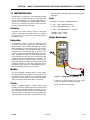
Multimeter Basics . . . . . . . . . . . . . . . . . . . . . . . . . . . . . . . . . . . . . . . . . . . . . . . . . . . . . . . . . . . . . .7-19
Grounding . . . . . . . . . . . . . . . . . . . . . . . . . . . . . . . . . . . . . . . . . . . . . . . . . . . . . . . . . . . . . . . 7-19
Backprobing . . . . . . . . . . . . . . . . . . . . . . . . . . . . . . . . . . . . . . . . . . . . . . . . . . . . . . . . . . . . . 7-19
Min/Max . . . . . . . . . . . . . . . . . . . . . . . . . . . . . . . . . . . . . . . . . . . . . . . . . . . . . . . . . . . . . . . . . 7-19
Polarity . . . . . . . . . . . . . . . . . . . . . . . . . . . . . . . . . . . . . . . . . . . . . . . . . . . . . . . . . . . . . . . . . . 7-19
Scale . . . . . . . . . . . . . . . . . . . . . . . . . . . . . . . . . . . . . . . . . . . . . . . . . . . . . . . . . . . . . . . . . . . 7-19
Voltage Measurement . . . . . . . . . . . . . . . . . . . . . . . . . . . . . . . . . . . . . . . . . . . . . . . . . . . . . . 7-19
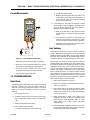
Resistance Measurement . . . . . . . . . . . . . . . . . . . . . . . . . . . . . . . . . . . . . . . . . . . . . . . . . . . 7-20
Continuity Measurement . . . . . . . . . . . . . . . . . . . . . . . . . . . . . . . . . . . . . . . . . . . . . . . . . . . . 7-20
Current Measurement . . . . . . . . . . . . . . . . . . . . . . . . . . . . . . . . . . . . . . . . . . . . . . . . . . . . . . 7-21
Checking Switches . . . . . . . . . . . . . . . . . . . . . . . . . . . . . . . . . . . . . . . . . . . . . . . . . . . . . . . . . . . . .7-21
Basic Check . . . . . . . . . . . . . . . . . . . . . . . . . . . . . . . . . . . . . . . . . . . . . . . . . . . . . . . . . . . . . . 7-21
Limit Switches . . . . . . . . . . . . . . . . . . . . . . . . . . . . . . . . . . . . . . . . . . . . . . . . . . . . . . . . . . . . 7-21
Automatic Switches . . . . . . . . . . . . . . . . . . . . . . . . . . . . . . . . . . . . . . . . . . . . . . . . . . . . . . . . 7-22
Switch Wiring - Low Side, High Side . . . . . . . . . . . . . . . . . . . . . . . . . . . . . . . . . . . . . . . . . . . 7-22
Applying Silicone Dielectric Compound to Electrical Connections . . . . . . . . . . . . . . . . . . . . . . . .7-22
AMP Connector . . . . . . . . . . . . . . . . . . . . . . . . . . . . . . . . . . . . . . . . . . . . . . . . . . . . . . . . . . . . . . . .7-23
Applying Silicone Dielectric Compound to AMP Connectors. . . . . . . . . . . . . . . . . . . . . . . . 7-23
Assembly . . . . . . . . . . . . . . . . . . . . . . . . . . . . . . . . . . . . . . . . . . . . . . . . . . . . . . . . . . . . . . . . 7-23
Disassembly. . . . . . . . . . . . . . . . . . . . . . . . . . . . . . . . . . . . . . . . . . . . . . . . . . . . . . . . . . . . . . 7-25
Wedge Lock. . . . . . . . . . . . . . . . . . . . . . . . . . . . . . . . . . . . . . . . . . . . . . . . . . . . . . . . . . . . . . 7-25
Service - Voltage Reading . . . . . . . . . . . . . . . . . . . . . . . . . . . . . . . . . . . . . . . . . . . . . . . . . . . 7-25
Deutsch Connectors . . . . . . . . . . . . . . . . . . . . . . . . . . . . . . . . . . . . . . . . . . . . . . . . . . . . . . . . . . . .7-27
DT/DTP Series Assembly. . . . . . . . . . . . . . . . . . . . . . . . . . . . . . . . . . . . . . . . . . . . . . . . . . . . 7-27
DT/DTP Series Disassembly . . . . . . . . . . . . . . . . . . . . . . . . . . . . . . . . . . . . . . . . . . . . . . . . . 7-27
HD30/HDP20 Series Assembly . . . . . . . . . . . . . . . . . . . . . . . . . . . . . . . . . . . . . . . . . . . . . . . 7-28
HD30/HDP20 Series Disassembly. . . . . . . . . . . . . . . . . . . . . . . . . . . . . . . . . . . . . . . . . . . . . 7-28
– JLG Lift –
3121829
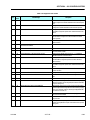
LIST OF FIGURES
FIGURE NO.
1-1.
1-2.
1-3.
1-4.
1-5.
1-6.
1-7.
1-8.
1-9.
2-1.
3-3.
3-1.
3-2.
3-3.
3-4.
3-5.
3-6.
3-7.
3-8.
3-9.
3-10.
3-11.
3-12.
3-13.
3-14.
3-15.
3-16.
3-17.
3-18.
3-19.
3-20.
3-21.
3-22.
4-1.
4-2.
4-3.
4-4.
4-5.
4-6.
4-7.
4-8.
4-9.
4-10.
4-11.
4-12.
4-13.
4-14.
3121829
TITLE
PAGE NO.
Serial Number Locations. . . . . . . . . . . . . . . . . . . . . . . . . . . . . . . . . . . . . . . . . . . . . . . . . . . . . . . . .1-5
Operator Maintenance & Lubrication Diagram . . . . . . . . . . . . . . . . . . . . . . . . . . . . . . . . . . . . . . . .1-6
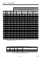
Torque Chart (SAE Fasteners - Sheet 1 of 7) . . . . . . . . . . . . . . . . . . . . . . . . . . . . . . . . . . . . . . . . .1-10
Torque Chart (SAE Fasteners - Sheet 2 of 7) . . . . . . . . . . . . . . . . . . . . . . . . . . . . . . . . . . . . . . . . .1-11
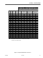
Torque Chart (SAE Fasteners - Sheet 3 of 7) . . . . . . . . . . . . . . . . . . . . . . . . . . . . . . . . . . . . . . . . .1-12
Torque Chart (SAE Fasteners - Sheet 4 of 7) . . . . . . . . . . . . . . . . . . . . . . . . . . . . . . . . . . . . . . . . .1-13
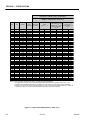
Torque Chart (METRIC Fasteners - Sheet 5 of 7). . . . . . . . . . . . . . . . . . . . . . . . . . . . . . . . . . . . . .1-14
Torque Chart (METRIC Fasteners - Sheet 6 of 7). . . . . . . . . . . . . . . . . . . . . . . . . . . . . . . . . . . . . .1-15
Torque Chart (METRIC Fasteners - Sheet 7 of 7). . . . . . . . . . . . . . . . . . . . . . . . . . . . . . . . . . . . . .1-16
Engine Operating Temperature Specifications - Kubota . . . . . . . . . . . . . . . . . . . . . . . . . . . . . . . .2-9
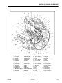
Spindle Assembly . . . . . . . . . . . . . . . . . . . . . . . . . . . . . . . . . . . . . . . . . . . . . . . . . . . . . . . . . . . . . .3-3
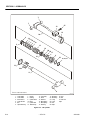
Drive Hub - Cutaway . . . . . . . . . . . . . . . . . . . . . . . . . . . . . . . . . . . . . . . . . . . . . . . . . . . . . . . . . . . .3-7
Drive Brake . . . . . . . . . . . . . . . . . . . . . . . . . . . . . . . . . . . . . . . . . . . . . . . . . . . . . . . . . . . . . . . . . . .3-9
Speed Sensor Orientation. . . . . . . . . . . . . . . . . . . . . . . . . . . . . . . . . . . . . . . . . . . . . . . . . . . . . . . .3-12
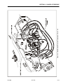
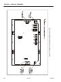
Frame Mounted Electrical Components - Sheet 1 of 2 . . . . . . . . . . . . . . . . . . . . . . . . . . . . . . . . .3-13
Frame Mounted Electrical Components - Sheet 2 of 2 . . . . . . . . . . . . . . . . . . . . . . . . . . . . . . . . .3-14
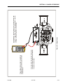
Voltage Checks . . . . . . . . . . . . . . . . . . . . . . . . . . . . . . . . . . . . . . . . . . . . . . . . . . . . . . . . . . . . . . . .3-15
Steering Components and Spindles. . . . . . . . . . . . . . . . . . . . . . . . . . . . . . . . . . . . . . . . . . . . . . . .3-18
Drive Components. . . . . . . . . . . . . . . . . . . . . . . . . . . . . . . . . . . . . . . . . . . . . . . . . . . . . . . . . . . . . .3-19
Tilt Sensor Location. . . . . . . . . . . . . . . . . . . . . . . . . . . . . . . . . . . . . . . . . . . . . . . . . . . . . . . . . . . . .3-20
Swing Motor - Cutaway . . . . . . . . . . . . . . . . . . . . . . . . . . . . . . . . . . . . . . . . . . . . . . . . . . . . . . . . . .3-21
Swing Motor - Exploded View . . . . . . . . . . . . . . . . . . . . . . . . . . . . . . . . . . . . . . . . . . . . . . . . . . . . .3-23
Swing Bearing Feeler Gauge Check. . . . . . . . . . . . . . . . . . . . . . . . . . . . . . . . . . . . . . . . . . . . . . . .3-39
Swing Bearing Tolerance Boom Placement . . . . . . . . . . . . . . . . . . . . . . . . . . . . . . . . . . . . . . . . . .3-40
Swing Bearing Tolerance Measuring Point. . . . . . . . . . . . . . . . . . . . . . . . . . . . . . . . . . . . . . . . . . .3-40
Swing Bearing Torquing Sequence . . . . . . . . . . . . . . . . . . . . . . . . . . . . . . . . . . . . . . . . . . . . . . . .3-42
Swing Components. . . . . . . . . . . . . . . . . . . . . . . . . . . . . . . . . . . . . . . . . . . . . . . . . . . . . . . . . . . . .3-44
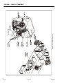
On Board Generator . . . . . . . . . . . . . . . . . . . . . . . . . . . . . . . . . . . . . . . . . . . . . . . . . . . . . . . . . . . .3-46
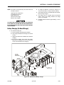
Batteries and Battery Charger. . . . . . . . . . . . . . . . . . . . . . . . . . . . . . . . . . . . . . . . . . . . . . . . . . . . .3-47
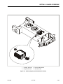
Battery Charger ((S/N 0300059350 to Present) . . . . . . . . . . . . . . . . . . . . . . . . . . . . . . . . . . . . . . .3-49
Generator Components . . . . . . . . . . . . . . . . . . . . . . . . . . . . . . . . . . . . . . . . . . . . . . . . . . . . . . . . .3-54
Generator System Analyzer Flow Chart . . . . . . . . . . . . . . . . . . . . . . . . . . . . . . . . . . . . . . . . . . . . .3-57
Generator. . . . . . . . . . . . . . . . . . . . . . . . . . . . . . . . . . . . . . . . . . . . . . . . . . . . . . . . . . . . . . . . . . . . .3-61
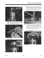
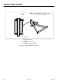
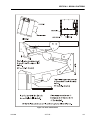
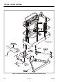
Location of Components - Boom Removal. . . . . . . . . . . . . . . . . . . . . . . . . . . . . . . . . . . . . . . . . . .4-1
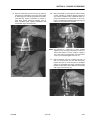
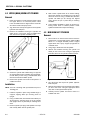
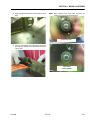
Upper Boom Lift Cylinder Removal. . . . . . . . . . . . . . . . . . . . . . . . . . . . . . . . . . . . . . . . . . . . . . . . .4-4
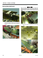
Mid Boom Lift Cylinder Removal. . . . . . . . . . . . . . . . . . . . . . . . . . . . . . . . . . . . . . . . . . . . . . . . . . .4-4
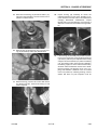
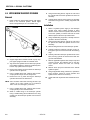
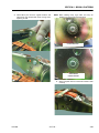
Lower Boom Lift Cylinder Removal. . . . . . . . . . . . . . . . . . . . . . . . . . . . . . . . . . . . . . . . . . . . . . . . .4-5
Upper Telescope Cylinder Removal . . . . . . . . . . . . . . . . . . . . . . . . . . . . . . . . . . . . . . . . . . . . . . . .4-6
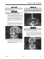
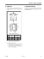
Wear Pad Thickness . . . . . . . . . . . . . . . . . . . . . . . . . . . . . . . . . . . . . . . . . . . . . . . . . . . . . . . . . . . .4-7
Platform Support Torque Values. . . . . . . . . . . . . . . . . . . . . . . . . . . . . . . . . . . . . . . . . . . . . . . . . . .4-8
Boom Limit Switches. . . . . . . . . . . . . . . . . . . . . . . . . . . . . . . . . . . . . . . . . . . . . . . . . . . . . . . . . . . .4-9
Platform Components and Attaching Hardware (M450A & E450A). . . . . . . . . . . . . . . . . . . . . . . .4-10
Location of Components - Articulating Jib Boom. . . . . . . . . . . . . . . . . . . . . . . . . . . . . . . . . . . . . .4-11
Load Sensing System . . . . . . . . . . . . . . . . . . . . . . . . . . . . . . . . . . . . . . . . . . . . . . . . . . . . . . . . . . .4-12
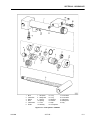
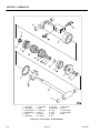
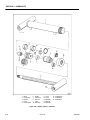
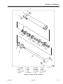
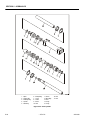
Rotary Actuator (Exploded View) . . . . . . . . . . . . . . . . . . . . . . . . . . . . . . . . . . . . . . . . . . . . . . . . . .4-14
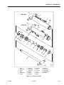
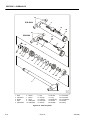
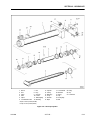
Rotary Actuator (Cutaway View) . . . . . . . . . . . . . . . . . . . . . . . . . . . . . . . . . . . . . . . . . . . . . . . . . . .4-15
Rotator Counterbalance Valve . . . . . . . . . . . . . . . . . . . . . . . . . . . . . . . . . . . . . . . . . . . . . . . . . . . .4-25
– JLG Lift –
vii
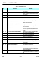
LIST OF FIGURES
FIGURE NO.
5-1.
5-2.
5-3.
5-4.
5-5.
5-6.
5-7.
5-8.
5-9.
5-10.
5-11.
5-12.
5-13.
5-14.
5-15.
5-16.
5-17.
5-18.
5-19.
5-20.
5-21.
5-22.
5-23.
5-24.
5-25.
5-26.
5-27.
6-1.
6-2.
6-3.
6-4.
7-1.
7-2.
7-3.
7-4.
7-5.
7-6.
7-7.
7-8.
7-9.
7-10.
7-11.
7-12.
7-13.
7-14.
7-15.
7-16.
7-17.
viii
TITLE
PAGE NO.
Cylinder Barrel Support. . . . . . . . . . . . . . . . . . . . . . . . . . . . . . . . . . . . . . . . . . . . . . . . . . . . . . . . . .5-4
Capscrew Removal . . . . . . . . . . . . . . . . . . . . . . . . . . . . . . . . . . . . . . . . . . . . . . . . . . . . . . . . . . . . .5-5
Cylinder Rod Support . . . . . . . . . . . . . . . . . . . . . . . . . . . . . . . . . . . . . . . . . . . . . . . . . . . . . . . . . . .5-5
Tapered Bushing Removal . . . . . . . . . . . . . . . . . . . . . . . . . . . . . . . . . . . . . . . . . . . . . . . . . . . . . . .5-5
Gar-Max Bearing Installation . . . . . . . . . . . . . . . . . . . . . . . . . . . . . . . . . . . . . . . . . . . . . . . . . . . . . .5-6
Rod Seal Installation . . . . . . . . . . . . . . . . . . . . . . . . . . . . . . . . . . . . . . . . . . . . . . . . . . . . . . . . . . . .5-6
Wiper Seal Installation. . . . . . . . . . . . . . . . . . . . . . . . . . . . . . . . . . . . . . . . . . . . . . . . . . . . . . . . . . .5-7
Installation of Head Seal Kit . . . . . . . . . . . . . . . . . . . . . . . . . . . . . . . . . . . . . . . . . . . . . . . . . . . . . .5-7
Piston Seal Kit Installation . . . . . . . . . . . . . . . . . . . . . . . . . . . . . . . . . . . . . . . . . . . . . . . . . . . . . . . .5-7
Tapered Bushing Installation . . . . . . . . . . . . . . . . . . . . . . . . . . . . . . . . . . . . . . . . . . . . . . . . . . . . .5-8
Seating the Tapered Bearing . . . . . . . . . . . . . . . . . . . . . . . . . . . . . . . . . . . . . . . . . . . . . . . . . . . . .5-8
Poly-Pak Piston Seal Installation. . . . . . . . . . . . . . . . . . . . . . . . . . . . . . . . . . . . . . . . . . . . . . . . . . .5-8
Rod Assembly Installation. . . . . . . . . . . . . . . . . . . . . . . . . . . . . . . . . . . . . . . . . . . . . . . . . . . . . . . .5-9
Jib Cylinder . . . . . . . . . . . . . . . . . . . . . . . . . . . . . . . . . . . . . . . . . . . . . . . . . . . . . . . . . . . . . . . . . . .5-10
Level Cylinder - A Models . . . . . . . . . . . . . . . . . . . . . . . . . . . . . . . . . . . . . . . . . . . . . . . . . . . . . . . .5-11
Level Cylinder - AJ & AJP Models. . . . . . . . . . . . . . . . . . . . . . . . . . . . . . . . . . . . . . . . . . . . . . . . . .5-12
Lower Lift Cylinder. . . . . . . . . . . . . . . . . . . . . . . . . . . . . . . . . . . . . . . . . . . . . . . . . . . . . . . . . . . . . .5-13
Mid Lift Cylinder. . . . . . . . . . . . . . . . . . . . . . . . . . . . . . . . . . . . . . . . . . . . . . . . . . . . . . . . . . . . . . . .5-14
Upper Lift Cylinder . . . . . . . . . . . . . . . . . . . . . . . . . . . . . . . . . . . . . . . . . . . . . . . . . . . . . . . . . . . . .5-15
Master Cylinder - A Models . . . . . . . . . . . . . . . . . . . . . . . . . . . . . . . . . . . . . . . . . . . . . . . . . . . . . . .5-16
Master Cylinder - AJ Models . . . . . . . . . . . . . . . . . . . . . . . . . . . . . . . . . . . . . . . . . . . . . . . . . . . . . .5-17
Steer Cylinder . . . . . . . . . . . . . . . . . . . . . . . . . . . . . . . . . . . . . . . . . . . . . . . . . . . . . . . . . . . . . . . . .5-18
Telescope Cylinder . . . . . . . . . . . . . . . . . . . . . . . . . . . . . . . . . . . . . . . . . . . . . . . . . . . . . . . . . . . . .5-19
Jib Valve Location . . . . . . . . . . . . . . . . . . . . . . . . . . . . . . . . . . . . . . . . . . . . . . . . . . . . . . . . . . . . . .5-22
Brake/Steer Valve Components . . . . . . . . . . . . . . . . . . . . . . . . . . . . . . . . . . . . . . . . . . . . . . . . . . .5-23
Main Valve Components Prior to S/N 62642 . . . . . . . . . . . . . . . . . . . . . . . . . . . . . . . . . . . . . . . . .5-24
Main Valve Components S/N 62642 to Present . . . . . . . . . . . . . . . . . . . . . . . . . . . . . . . . . . . . . . .5-25
Control Module Location. . . . . . . . . . . . . . . . . . . . . . . . . . . . . . . . . . . . . . . . . . . . . . . . . . . . . . . . .6-1
Analyzer Flow Chart (Software Version 3.x) - Sheet 1 of 3. . . . . . . . . . . . . . . . . . . . . . . . . . . . . . .6-17
Analyzer Flow Chart (Software Version 3.x) - Sheet 2 of 3. . . . . . . . . . . . . . . . . . . . . . . . . . . . . . .6-18
Analyzer Flow Chart (Software Version 3.x) - Sheet 3 of 3. . . . . . . . . . . . . . . . . . . . . . . . . . . . . . .6-19
Voltage Measurement (DC). . . . . . . . . . . . . . . . . . . . . . . . . . . . . . . . . . . . . . . . . . . . . . . . . . . . . . .7-19
Resistance Measurement . . . . . . . . . . . . . . . . . . . . . . . . . . . . . . . . . . . . . . . . . . . . . . . . . . . . . . . .7-20
Continuity Measurement . . . . . . . . . . . . . . . . . . . . . . . . . . . . . . . . . . . . . . . . . . . . . . . . . . . . . . . . .7-20
Current Measurement (DC). . . . . . . . . . . . . . . . . . . . . . . . . . . . . . . . . . . . . . . . . . . . . . . . . . . . . . .7-21
Connector Assembly Figure 1 . . . . . . . . . . . . . . . . . . . . . . . . . . . . . . . . . . . . . . . . . . . . . . . . . . . .7-23
AMP Connector . . . . . . . . . . . . . . . . . . . . . . . . . . . . . . . . . . . . . . . . . . . . . . . . . . . . . . . . . . . . . . . .7-23
Connector Assembly Figure 2 . . . . . . . . . . . . . . . . . . . . . . . . . . . . . . . . . . . . . . . . . . . . . . . . . . . .7-24
Connector Assembly Figure 3 . . . . . . . . . . . . . . . . . . . . . . . . . . . . . . . . . . . . . . . . . . . . . . . . . . . .7-24
Connector Assembly Figure 4 . . . . . . . . . . . . . . . . . . . . . . . . . . . . . . . . . . . . . . . . . . . . . . . . . . . .7-24
Connector Disassembly . . . . . . . . . . . . . . . . . . . . . . . . . . . . . . . . . . . . . . . . . . . . . . . . . . . . . . . . .7-25
Connector Installation . . . . . . . . . . . . . . . . . . . . . . . . . . . . . . . . . . . . . . . . . . . . . . . . . . . . . . . . . . .7-26
DT/DTP Contact Installation . . . . . . . . . . . . . . . . . . . . . . . . . . . . . . . . . . . . . . . . . . . . . . . . . . . . . .7-27
DT/DTP Contact Removal . . . . . . . . . . . . . . . . . . . . . . . . . . . . . . . . . . . . . . . . . . . . . . . . . . . . . . . .7-27
HD/HDP Contact Installation. . . . . . . . . . . . . . . . . . . . . . . . . . . . . . . . . . . . . . . . . . . . . . . . . . . . . .7-28
HD/HDP Locking Contacts Into Position . . . . . . . . . . . . . . . . . . . . . . . . . . . . . . . . . . . . . . . . . . . .7-28
HD/HDP Contact Removal . . . . . . . . . . . . . . . . . . . . . . . . . . . . . . . . . . . . . . . . . . . . . . . . . . . . . . .7-28
HD/HDP Unlocking Contacts . . . . . . . . . . . . . . . . . . . . . . . . . . . . . . . . . . . . . . . . . . . . . . . . . . . . .7-28
– JLG Lift –
3121829
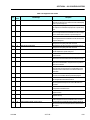
LIST OF FIGURES
FIGURE NO.
7-18.
7-19.
7-20.
7-21.
7-22.
7-23.
7-24.
7-25.
7-26.
7-27.
7-28.
7-29.
7-30.
7-31.
7-32.
3121829
TITLE
PAGE NO.
Electrical Components Installation - Sheet 1 . . . . . . . . . . . . . . . . . . . . . . . . . . . . . . . . . . . . . . . . .7-30
Electrical Components Installation - Sheet 2 . . . . . . . . . . . . . . . . . . . . . . . . . . . . . . . . . . . . . . . . .7-31
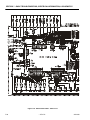
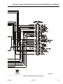
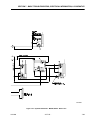
Electrical Schematic - Sheet 1 of 6 . . . . . . . . . . . . . . . . . . . . . . . . . . . . . . . . . . . . . . . . . . . . . . . . .7-32
Electrical Schematic - Sheet 2 of 6 . . . . . . . . . . . . . . . . . . . . . . . . . . . . . . . . . . . . . . . . . . . . . . . . .7-33
Electrical Schematic - Sheet 3 of 6 . . . . . . . . . . . . . . . . . . . . . . . . . . . . . . . . . . . . . . . . . . . . . . . . .7-34
Electrical Schematic - Sheet 4 of 6 . . . . . . . . . . . . . . . . . . . . . . . . . . . . . . . . . . . . . . . . . . . . . . . . .7-35
Electrical Schematic - Sheet 5 of 6 . . . . . . . . . . . . . . . . . . . . . . . . . . . . . . . . . . . . . . . . . . . . . . . . .7-36
Electrical Schematic - Sheet 6 of 6 . . . . . . . . . . . . . . . . . . . . . . . . . . . . . . . . . . . . . . . . . . . . . . . . .7-37
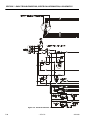
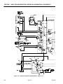
Hydraulic Schematic - M450A/E450A - Sheet 1 of 2 . . . . . . . . . . . . . . . . . . . . . . . . . . . . . . . . . . .7-38
Hydraulic Schematic - M450A/E450A - Sheet 2 of 2 . . . . . . . . . . . . . . . . . . . . . . . . . . . . . . . . . . .7-39
Hydraulic Schematic - M450A/E450A - Sheet 1 of 2 . . . . . . . . . . . . . . . . . . . . . . . . . . . . . . . . . . .7-40
Hydraulic Schematic - M450A/E450A - Sheet 2 of 2 . . . . . . . . . . . . . . . . . . . . . . . . . . . . . . . . . . .7-41
Hydraulic Schematic - M450AJ/E450AJ - Sheet 1 of 2. . . . . . . . . . . . . . . . . . . . . . . . . . . . . . . . . .7-42
Hydraulic Schematic - M450AJ/E450AJ - Sheet 2 of 2. . . . . . . . . . . . . . . . . . . . . . . . . . . . . . . . . .7-43
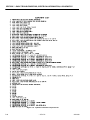
Hydraulic Schematic Component List . . . . . . . . . . . . . . . . . . . . . . . . . . . . . . . . . . . . . . . . . . . . . .7-44
– JLG Lift –
ix
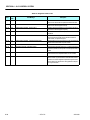
LIST OF TABLES
TABLE NO.
1-1
1-2
1-3
1-4
1-5
1-6
1-7
1-8
1-9
1-10
1-11
1-12
1-13
1-14
1-15
1-16
1-17
1-18
1-19
2-1
2-2
2-3
3-1
3-2
3-3
3-11
3-4
3-5
3-6
3-7
3-8
3-9
3-10
3-11
4-1
4-1
5-1
5-2
5-3
5-4
5-5
6-1
6-2
6-3
6-4
6-5
6-6
6-7
6-8
7-1
7-2
7-3
7-4
7-5
7-6
x
TITLE
PAGE NO.
Operating Specifications . . . . . . . . . . . . . . . . . . . . . . . . . . . . . . . . . . . . . . . . . . . . . . . . . . . . . . . . .1-1
Capacities . . . . . . . . . . . . . . . . . . . . . . . . . . . . . . . . . . . . . . . . . . . . . . . . . . . . . . . . . . . . . . . . . . . .1-1
Tire Specifications . . . . . . . . . . . . . . . . . . . . . . . . . . . . . . . . . . . . . . . . . . . . . . . . . . . . . . . . . . . . . .1-1
Generator. . . . . . . . . . . . . . . . . . . . . . . . . . . . . . . . . . . . . . . . . . . . . . . . . . . . . . . . . . . . . . . . . . . . .1-1
Dimensional Data . . . . . . . . . . . . . . . . . . . . . . . . . . . . . . . . . . . . . . . . . . . . . . . . . . . . . . . . . . . . . .1-1
Drive System . . . . . . . . . . . . . . . . . . . . . . . . . . . . . . . . . . . . . . . . . . . . . . . . . . . . . . . . . . . . . . . . . .1-2
Hydraulic Pump/Electric Motor . . . . . . . . . . . . . . . . . . . . . . . . . . . . . . . . . . . . . . . . . . . . . . . . . . . .1-2
Generator. . . . . . . . . . . . . . . . . . . . . . . . . . . . . . . . . . . . . . . . . . . . . . . . . . . . . . . . . . . . . . . . . . . . .1-2
Function Speeds . . . . . . . . . . . . . . . . . . . . . . . . . . . . . . . . . . . . . . . . . . . . . . . . . . . . . . . . . . . . . . .1-2
Pressure Settings - Prior to S/N 0300062642 . . . . . . . . . . . . . . . . . . . . . . . . . . . . . . . . . . . . . . . . .1-3
Pressure Settings - S/N 0300062642 to Present . . . . . . . . . . . . . . . . . . . . . . . . . . . . . . . . . . . . . .1-3
Torque Requirements . . . . . . . . . . . . . . . . . . . . . . . . . . . . . . . . . . . . . . . . . . . . . . . . . . . . . . . . . . .1-4
Hydraulic Oil . . . . . . . . . . . . . . . . . . . . . . . . . . . . . . . . . . . . . . . . . . . . . . . . . . . . . . . . . . . . . . . . . .1-4
Mobil DTE 11M Specs. . . . . . . . . . . . . . . . . . . . . . . . . . . . . . . . . . . . . . . . . . . . . . . . . . . . . . . . . . .1-4
Mobil EAL 224H Specs . . . . . . . . . . . . . . . . . . . . . . . . . . . . . . . . . . . . . . . . . . . . . . . . . . . . . . . . . .1-4
Critical Stability Weights . . . . . . . . . . . . . . . . . . . . . . . . . . . . . . . . . . . . . . . . . . . . . . . . . . . . . . . . .1-4
Cylinder Specifications . . . . . . . . . . . . . . . . . . . . . . . . . . . . . . . . . . . . . . . . . . . . . . . . . . . . . . . . . .1-5
Major Component Weights . . . . . . . . . . . . . . . . . . . . . . . . . . . . . . . . . . . . . . . . . . . . . . . . . . . . . . .1-5
Lubrication Specifications. . . . . . . . . . . . . . . . . . . . . . . . . . . . . . . . . . . . . . . . . . . . . . . . . . . . . . . .1-7
Inspection and Maintenance. . . . . . . . . . . . . . . . . . . . . . . . . . . . . . . . . . . . . . . . . . . . . . . . . . . . . .2-2
Cylinder Drift . . . . . . . . . . . . . . . . . . . . . . . . . . . . . . . . . . . . . . . . . . . . . . . . . . . . . . . . . . . . . . . . . .2-4
Inspection and Preventive Maintenance Schedule . . . . . . . . . . . . . . . . . . . . . . . . . . . . . . . . . . . .2-6
Wheel Torque Chart . . . . . . . . . . . . . . . . . . . . . . . . . . . . . . . . . . . . . . . . . . . . . . . . . . . . . . . . . . . .3-2
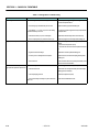
Drive Brake Diagnosis . . . . . . . . . . . . . . . . . . . . . . . . . . . . . . . . . . . . . . . . . . . . . . . . . . . . . . . . . . .3-10
Swing Motor Troubleshooting. . . . . . . . . . . . . . . . . . . . . . . . . . . . . . . . . . . . . . . . . . . . . . . . . . . . .3-22
Battery Charger Fault Codes (Delta-Q). . . . . . . . . . . . . . . . . . . . . . . . . . . . . . . . . . . . . . . . . . . . . .3-48
Battery Algorithms . . . . . . . . . . . . . . . . . . . . . . . . . . . . . . . . . . . . . . . . . . . . . . . . . . . . . . . . . . . . . .3-52
RBS Prestart Sequence. . . . . . . . . . . . . . . . . . . . . . . . . . . . . . . . . . . . . . . . . . . . . . . . . . . . . . . . . .3-55
RBS Startup Sequence . . . . . . . . . . . . . . . . . . . . . . . . . . . . . . . . . . . . . . . . . . . . . . . . . . . . . . . . . .3-55
RBS Shutdown Sequence. . . . . . . . . . . . . . . . . . . . . . . . . . . . . . . . . . . . . . . . . . . . . . . . . . . . . . . .3-55
Generator System Flash Codes . . . . . . . . . . . . . . . . . . . . . . . . . . . . . . . . . . . . . . . . . . . . . . . . . . .3-56
Controller Interface Pin Assignments . . . . . . . . . . . . . . . . . . . . . . . . . . . . . . . . . . . . . . . . . . . . . . .3-65
RBS Alarms and Flash Codes. . . . . . . . . . . . . . . . . . . . . . . . . . . . . . . . . . . . . . . . . . . . . . . . . . . . .3-68
Troubleshooting . . . . . . . . . . . . . . . . . . . . . . . . . . . . . . . . . . . . . . . . . . . . . . . . . . . . . . . . . . . . . . .3-69
Wear Pad Thickness . . . . . . . . . . . . . . . . . . . . . . . . . . . . . . . . . . . . . . . . . . . . . . . . . . . . . . . . . . . .4-7
Troubleshooting . . . . . . . . . . . . . . . . . . . . . . . . . . . . . . . . . . . . . . . . . . . . . . . . . . . . . . . . . . . . . . .4-27
Cylinder Head and Tapered Bushing Torque Specifications . . . . . . . . . . . . . . . . . . . . . . . . . . . . .5-9
Cylinder Piston Nut Torque Specifications) . . . . . . . . . . . . . . . . . . . . . . . . . . . . . . . . . . . . . . . . . .5-9
Holding Valve Torque Specifications . . . . . . . . . . . . . . . . . . . . . . . . . . . . . . . . . . . . . . . . . . . . . . .5-9
Pressure Settings - Prior to S/N 0300062642 . . . . . . . . . . . . . . . . . . . . . . . . . . . . . . . . . . . . . . . . .5-22
Pressure Settings - S/N 0300062642 to Present . . . . . . . . . . . . . . . . . . . . . . . . . . . . . . . . . . . . . .5-22
Personality Ranges/Defaults . . . . . . . . . . . . . . . . . . . . . . . . . . . . . . . . . . . . . . . . . . . . . . . . . . . . . .6-6
Machine Setup Descriptions . . . . . . . . . . . . . . . . . . . . . . . . . . . . . . . . . . . . . . . . . . . . . . . . . . . . . .6-9
JLG Control System Flash Codes. . . . . . . . . . . . . . . . . . . . . . . . . . . . . . . . . . . . . . . . . . . . . . . . . .6-10
Help Descriptions and Fault Flash Codes . . . . . . . . . . . . . . . . . . . . . . . . . . . . . . . . . . . . . . . . . . .6-11
DIAGNOSTICS - Menu Descriptions. . . . . . . . . . . . . . . . . . . . . . . . . . . . . . . . . . . . . . . . . . . . . . . .6-20
System Test Descriptions . . . . . . . . . . . . . . . . . . . . . . . . . . . . . . . . . . . . . . . . . . . . . . . . . . . . . . . .6-22
System Test Messages . . . . . . . . . . . . . . . . . . . . . . . . . . . . . . . . . . . . . . . . . . . . . . . . . . . . . . . . . .6-23
Diagnostic Fault Codes. . . . . . . . . . . . . . . . . . . . . . . . . . . . . . . . . . . . . . . . . . . . . . . . . . . . . . . . . .6-27
Platform Assembly - Troubleshooting. . . . . . . . . . . . . . . . . . . . . . . . . . . . . . . . . . . . . . . . . . . . . . .7-2
Boom Assembly - Troubleshooting . . . . . . . . . . . . . . . . . . . . . . . . . . . . . . . . . . . . . . . . . . . . . . . .7-4
Turntable Assembly - Troubleshooting. . . . . . . . . . . . . . . . . . . . . . . . . . . . . . . . . . . . . . . . . . . . . .7-9
Chassis Assembly - Troubleshooting . . . . . . . . . . . . . . . . . . . . . . . . . . . . . . . . . . . . . . . . . . . . . . .7-10
Hydraulic System - Troubleshooting . . . . . . . . . . . . . . . . . . . . . . . . . . . . . . . . . . . . . . . . . . . . . . .7-15
Electrical System - Troubleshooting . . . . . . . . . . . . . . . . . . . . . . . . . . . . . . . . . . . . . . . . . . . . . . . .7-17
– JLG Lift –
3121829
SECTION 1 - SPECIFICATIONS
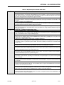
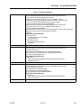
SECTION 1. SPECIFICATIONS
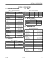
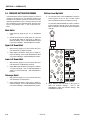
1.1
OPERATING SPECIFICATIONS
1.3
TIRES
Table 1-1. Operating Specifications
Maximum Work Load (Capacity)
Unrestricted:
Table 1-3. Tire Specifications
IN240/55-17.5 IN240/55-17.5
Size
500 lb. (230 kg)
3.2 mph (5.2 kph)
Travel Speed
30%
Maximum Travel Grade (Gradeablility
E
Load Range
10
10
--
Foam-Filled
Solid, NonMarking
5°
Maximum Travel Grade (Side Slope)
Maximum Height: (stowed)
E450A/M450A
E450AJ/M450AJ
6 ft. 6.25 in. (1.9 m)
6 ft. 7 in. (2.0 m)
Maximum Horizontal Platform Reach
E450A
E450AJ
23 ft. 1in.(7.0 m)
23 ft. 9 in. (7.24 m)
Input
Turning Radius (Curb to Curb)
15 ft. 3 in. (4.65 m)
Quantity of Batteries
2 ft. (0.61 m)
Turning Radius (inside)
Maximum Tire Load:
M450A, E450A
M450AJ, E450AJ
6100 lbs. (2,767 kg)
6900 lbs. (3,130 kg)
Ground Bearing Pressure
M450A, E450A
M450AJ, E450AJ
64 psi (4.5 kg/cm2)
75 psi (5.2 kg/cm2)
System Voltage
48 volts
Battery Life per Charge
7 hours continuous
Battery Recharge Time
Charger
Generator
17 hours from full discharge
6.2 hours
Gross Machine Weight (Platform Empty)
E450A/M450A
E450AJ/M450AJ
1.2
13,100 lb. (5942 kg)
15,100 lb. (6804 kg)
CAPACITIES
1.4
BATTERY CHARGER
Table 1-4. Generator
110 VAC,60 HZ
Output
48 VDC (25 Amps)
Battery Spec
1.5
DIMENSIONAL DATA
Table 1-5. Dimensional Data
Machine Length (stowed)
M450A, E450A
M450AJ, E450AJ
18 ft. 8.0 in. (5.69 m)
21 ft. 2 in. (6.45 m)
Up and Over Platform Height
M450A, E450A
M450AJ, E450AJ
24 ft. 7 in. (7.49 m)
25 ft. 3 in. (7.7 m)
Horizontal Reach @ Maximum
Up and Over
M450 A, E450A
M450AJ, E450AJ
23 ft. 1 in. (7.0 m)
23 ft. 9 in. (7.24 m)
5 ft. 9 in. (1.75 m)
Wheel Base
6 ft. 7.0 in. (2.00 m)
5 Gallons (19 L) w/ 10% air space
Working Height
51 ft. 0 in. (15.54 m)
9 Gallons (34.1 L)
Platform Height
45 ft. 0 in. (13.72 m)
Generator Fuel Tank
4 Gallons (15.1 L)
Hydraulic System (Including Tank)
Torque Hub, Drive*
*Torque hubs should be one half full of lubricant.
17 ounces (0.50 L)
Track Width
Tail Swing (Any Position)
Ground Clearance
M450, E450
M450AJ, E450AJ
3121829
8
6 Volt, 370 Amp Hour
(20 hour rate)
Machine Width
Table 1-2. Capacities
Hydraulic Oil Tank
--
90 psi (6.2 Bar)
Ply Rating
Tire Pressure
26x7x20
E
– JLG Lift –
5 ft. 0 in. (1.51 m)
0
8.5 in. (0.22 m)
8 in. (0.20 m)
1-1
SECTION 1 - SPECIFICATIONS
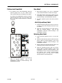
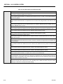
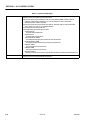
1.6
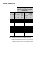
1.9
DRIVE SYSTEM
FUNCTION SPEEDS
Table 1-6. Drive System
Drive Motor
48 VDC, 12.5 H.P. @ 3200 rpm. continuous,
rotation - reversible
Drive Brake
1.7
Table 1-9. Function Speeds
Spring-applied, hydraulically released
HYDRAULIC PUMP/ELECTRIC MOTOR
ASSEMBLY
Table 1-7. Hydraulic Pump/Electric Motor
Motor
48 VDC, 2.14 H.P. @ 2700 rpm
Pump
0.098 in.[3]/rev. (1.6 cm[3]/rev.)
Pump Output
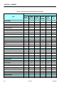
1.8
Function
2.96 gpm (11.2 lpm) @ 3200 psi (222 Bar)
GENERATOR
Table 1-8. Generator
Alternator Output
RPM’s under max. load
Start Battery
Seconds
Main Lift Up
30-24
Main Lift Down
29-23
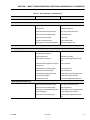
Turntable Swing Right & Left 360°
81-67*
Telescope Out - E450AJ, M450AJ
12-9
Telescope Out - E450A, M450A
18-14
Telescope In - E450AJ, M450AJ
19-15
Telescope In - E450A, M450A
28-23
Platform Rotate - Right & Left 180° - E450AJ, M450AJ
20-24**
Platform Rotate - Right & Left 180° - E450A, M450A
17-14**
Jib Up
25-26
Jib Down
24-25
Lower Lift Up
33-27
Lower Lift Down
58 volts @ 45 Amps
3100
12 volts
Engine Oil
10W30 (Refer to
Engine Manual)
Dynamo
12 volt, 15 amp DC
Dynamo Output Fuse
20 amps DC
Control Fuse
15 amps DC
26-22
High Drive - Fwd.& Rev.
(200 ft.)
42-44***
3.2 mph. (5.1 kph)
Drive above Horiz. (ANSI) - Fwd.& Rev.
(50 ft.)
50-53***
0.64 mph (1 kph)
Drive above Horiz. (CE) - Fwd.& Rev. E450AJ/
M450AJ
(50 ft.)
107-112***
0.32 mph (0.5 kph)
Drive above Horiz.(CE) - Fwd.& Rev. E450A/M450A
(50 f t.)
67-71***
0 .48 mph. (0.8 kph)
*Swing Left to Swing Right should be within 10% of each other.
**Swing Left to Swing Right should be within 15% of each other.
***Drive Forward to Drive Reverse should be within 10% of each other.
4150273 N
1-2
– JLG Lift –
3121829
SECTION 1 - SPECIFICATIONS
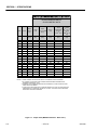
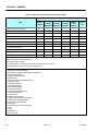
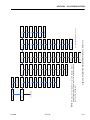
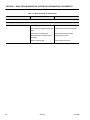
1.10 PRESSURE SETTINGS
Table 1-11. Pressure Settings - S/N 0300062642 to
Present
Table 1-10. Pressure Settings - Prior to S/N 0300062642
Circuit
Circuit
PSI
PSI
Bar
Lift Down Relief
800
55
Tower Lift Down Relief (E/M450AJ)
Prior to S/N 86022
1700
117
Tower Lift Down Relief (E/M450AJ)
S/N 86022 to Present
2600
179
Tower Lift Down Relief (E/M450A)
Prior to S/N 91053
1700
117
Tower Lift Down Relief (E/M450A)
S/N 91053 to Present
2600
179
Telescope Relief (A)
3000
207
Telescope Relief (AJ & AJP)
3100
214
Platform Level Up Relief
3000
207
Platform Level Down Relief
1200
83
Steer Relief
2300
159
Main Relief - E450A/M450A
3200
221
Main Relief - E450AJ/M450AJ
3400
234
2200
152
Releveling Relief (E/M450AJ)
Prior to S/N 86022
1200
83
Releveling Relief (E/M450AJ)
S/N 86022 to Present
2200
152
Releveling Relief (E/M450A)
Prior to S/N 91053
1200
83
Releveling Relief (E/M450A)
S/N 91053 to Present
2200
152
Bar
Main Control Valve
Main Control Valve
Lift Down Relief
550
38
Tower Lift Down Relief
1700
117
Telescope In Relief (A/AJ)
2150
148
Telescope In Relief (AJP)
3000
207
Platform Level Up Relief
2500
172
Platform Level Down Relief
1500
103
Steer Relief
2300
159
Main Relief - E450A/M450A
3200
221
Main Relief - E450AJ/M450AJ
3400
234
Brake/Steer Valve
Jib Valve
Brake/Steer Valve
Jib Relief (Up and Down)
1500
103
Releveling Valve
Releveling Relief
1200
83
Jib Valve
Jib Relief (Up and Down)
Releveling Valve
3121829
– JLG Lift –
1-3
SECTION 1 - SPECIFICATIONS
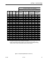
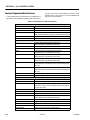
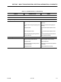
1.11 TORQUE SPECIFICATIONS
Table 1-14. Mobil DTE 11M Specs
Table 1-12. Torque Requirements
ISO Viscosity Grade
#15
Torque Value
Interval Hours
Gravity API
31.9
Wheel Lugs
170 ft. lbs.
(230 Nm)
150
Pour Point, Max
-40°F (-40°C)
Swing Bearing
((Loctite)
190 ft. lbs.
(260 Nm)
50/600*
Flash Point, Min.
330°F (166°C)
Description
Viscosity
at 40° C
15 cSt
at 100° C
4.1 cSt
at 100° F
80 SUS
at 210° F
43 SUS
cp at -30° F
3.200
Viscosity Index
140
* Check swing bearing bolts for security after
first 50 hours of operation and every 600 hours
thereafter.
1.12 LUBRICATION SPECIFICATIONS
Refer to Section 1.17, Operator Maintenance & Lubrication, for specific lubrication procedures.
Table 1-15. Mobil EAL 224H Specs
Hydraulic Oil
NOTE:
Type
Biodegradable Vegetable Oil
Hydraulic oils must have anti-wear qualities at least
to API Service Classification GL-3, and sufficient
chemical stability for mobile hydraulic system service.
ISO Viscosity Grade
32/46
Flash Point, Min.
428°F (220°C)
Aside from JLG recommendations, it is not advisable to mix oils of different brands or types, as they
may not contain the same required additives or be
of comparable viscosities. If use of hydraulic oil
other than Mobil DTE 11M is desired, contact JLG
Industries for proper recommendations.
Operating Temp.
0 to 180°F (-17 to 162°C)
Weight
7.64 lb. per gal.
(0.9 kg per liter)
-25°F (-32°C)
at 40° C
37 cSt
at 100° C
8.4 cSt
Viscosity Index
213
NOTE:
Must be stored above 32°F (0°C)
S.A.E. Viscosity
Grade
+0° to + 180° F
(-18° to +83° C)
10W
+0° to + 210° F
(-18° to +99° C)
10W-20, 10W30
+50° to + 210° F
(+10° to +99° C
.922
Pour Point, Max
Viscosity
Table 1-13. Hydraulic Oil
Hydraulic System
Operating
Temperature Range
Specific Gravity
1.13 CRITICAL STABILITY WEIGHTS
Table 1-16. Critical Stability Weights
20W-20
LB.
KG.
Counterweight
Component
3850
1746
Tire & Wheel (foam-filled)
207
94
Platform (4ft [1.2 m])
90
41
Platform (5 ft [1.5 m])
100
45
Battery (each)
120
54
DO NOT REPLACE ITEMS CRITICAL TO STABILITY WITH ITEMS
OF DIFFERENT WEIGHT OR SPECIFICATION (FOR EXAMPLE:
BATTERIES, FILLED TIRES, PLATFORM) DO NOT MODIFY UNIT IN
ANY WAY TO AFFECT STABILITY.
1-4
– JLG Lift –
3121829
SECTION 1 - SPECIFICATIONS
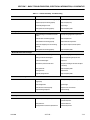
1.14 CYLINDER SPECIFICATIONS
NOTE: All dimensions are given in inches (in.), with the metric equivalent, millimeters (mm), given in parentheses.
Table 1-17. Cylinder Specifications
Cylinder
Bore
Stroke
Rod Dia.
Upper Lift
Cylinder
3.00
(76.2)
28.3125
(719.1)
1.50
(38.1)
Mid Lift Cylinder
3.00
(76.2)
21.25
(539.7)
1.50
(38.1)
Lower Lift Cylinder
4.00
(101.6)
23.25
(590.5)
2.25
(57.1)
Telescope Cylinder
2.00
(50.8)
92
(2337)
1.25
(31.8)
Master Cylinder (E/M450A)
2.00
(50.8)
9.375
(238.1)
1.00
(25.4)
Master Cylinder (E/M450AJ)
3.00
(75)
11.5
(292)
1.25
(32)
Slave Cylinder (E/M450A)
2.00
(50.8)
9.375
(238.1)
1.00
(25.4)
Slave Cylinder (E/M450AJ)
3.00
(75)
11.6
(295.5)
1.25
(32)
Rotator Cylinder
1.875
(47.6)
15.250
(387.3)
1.00
(25.4)
Steer Cylinder
(Double Rod)
2.50
(63.5)
4.06
(103.1)
1.75
(44.5)
SELECT LIFTING EQUIPMENT WITH CAPACITY CAPABLE OF
SAFELY SUPPORTING WEIGHT.
1.16 SERIAL NUMBER LOCATIONS
For machine identification, a serial number plate is
affixed to the left rear of frame, in front of left rear
wheel. If the serial number plate is damaged or missing, the machine serial number is stamped on the top
left side of the frame and the top left side of the turntable. In addition, the serial number is stamped on top of
the end of the upper boom, mid boom, and lower
boom at the left rear of the booms.
SERIAL NUMBER
TURNTABLE
SERIAL NUMBER FRAME
1.15 MAJOR COMPONENT WEIGHTS
SERIAL NUMBER PLATE
Table 1-18. Major Component Weights
Component
LB.
KG.
Platform and Support
215
97.5
Upper Boom Complete
810
367
Mid Boom Complete
550
249
Lower Boom Complete
550
249
Upper Lift Cylinder
89
40
Mid Lift Cylinder
95
43
Lower Lift Cylinder
110
50
Telescope Cylinder
85
38.5
Upper Upright
225
102
Lower Upright
97
44
Turntable
948
430
Battery Box (incl. batteries)
600
272
Chassis (w/ pneu. tires)
4,295
1948
Chassis (w/ foam-filled tires)
4,695
2130
Counterweight
3850
1746
11,800
5352
Machine Complete
3121829
Figure 1-1. Serial Number Locations
– JLG Lift –
1-5
SECTION 1 - SPECIFICATIONS
Figure 1-2. Operator Maintenance & Lubrication Diagram
1-6
– JLG Lift –
3121829
SECTION 1 - SPECIFICATIONS
1.17 OPERATOR MAINTENANCE &
LUBRICATION
NOTE:
2. Swing Bearing/Worm Gear Teeth
The following numbers correspond to those in Figure 1-2., Operator Maintenance & Lubrication Diagram.
Table 1-19. Lubrication Specifications.
KEY
SPECIFICATIONS
MPG
Multipurpose Grease having a minimum dripping point of 350
degrees F. Excellent water resistance and adhesive qualities;
and being of extreme pressure type (Timken OK 40 pounds minimum).
EPGL
Extreme Pressure Gear Lube (oil) meeting API Service Classification GL-5 or Mil-Spec Mil-L-2105.
HO
Hydraulic Oil. Mobil DTE-11M
OG*
Open Gear Lube - Tribol Molub-Alloy 936 Open Gear Compound. (JLG Part No. 3020027)
BG*
Bearing Grease (JLG Part No. 3020029) Mobilith SHA 460.
LL
Synthetic Lithium Lubricant, Gredag 741 Grease. (JLG Part No.
3020022)
EO
Engine (crankcase) Oil. Gas - API SF/SG class, MIL-L-2104.
Diesel - API CC/CD class, MIL-L-2104B/MIL-L-2104C.
Lube Point(s) - 2 Grease Fittings
Capacity - Spray On
Lube - Mobiltac 375NC
Interval - A/R
Comments - If necessary install grease fittings into
worm gear housing and grease bearings.
DO NOT OVERGREASE BEARINGS. OVERGREASING BEARINGS
WILL RESULT IN BLOWING OUTER SEAL IN HOUSING.
*MPG may be substituted for these lubricants, if necessary, but service
intervals will be reduced.
LUBRICATION INTERVALS ARE BASED ON MACHINE OPERATION
UNDER NORMAL CONDITIONS. FOR MACHINES USED IN MULTISHIFT OPERATIONS AND/OR EXPOSED TO HOSTILE ENVIRONMENTS OR CONDITIONS, LUBRICATION FREQUENCIES MUST BE
INCREASED ACCORDINGLY.
3. Hydraulic Tank
1. Swing Bearing
Lube Point(s) - 2 Grease Fittings
Capacity - A/R
Lube - MPG
Interval - Every 3 months or 150 hrs of operation
Comments - Remote Access
Lube Point(s) - Fill Cap
Capacity - 4 Gal. (15.1 L)
Lube - HO
Interval - Check Level daily; Change every 2 years or
1200 hours of operation.
Comments - On new machines, those recently overhauled, or after changing hydraulic oil, operate
all systems a minimum of two complete cycles
and recheck oil level in reservoir.
3121829
– JLG Lift –
1-7
SECTION 1 - SPECIFICATIONS
4. Hydraulic Return Filter
6. Wheel Bearings
Lube Point(s) - Repack
Capacity - A/R
Lube - MPG
Interval - Every 2 years or 1200 hours of operation
Interval - Change after first 50 hrs. and every 6
months or 300 hrs. thereafter.
Comments - Under certain conditions, it may be
necessary to replace the hydraulic filter on a
more frequent basis. A common symptom of a
dirty filter is sluggishness experienced in hydraulic functions.
7. Spindles/Bushing
Capacity - A/R
Lube - Lithium Lubricant
Interval - Every 2 years or 1200 hours of operation
Comments - At Spindle/Bushing Replacement; Coat
I.D. of bushings prior to installing king pins.
8. Boom Pivot Pins/Bushing
5. Wheel Drive Hub
Capacity - A/R
Lube - Lithium Lubricant
Interval - Every 2 years or 1200 hours of operation
Comments - At boom pivot pins/bushing replacement; Coat I.D. of bushings prior to installing
pivot pins.
Lube Point(s) - Level/Fill Plug
Capacity - 17 oz. (1/2 Full)
Lube - EPGL
Interval - Check level every 3 months or 150 hrs of
operation; change every 2 years or 1200 hours
of operation
1-8
– JLG Lift –
3121829
SECTION 1 - SPECIFICATIONS
9. Engine
Lube Point(s) - Fill Cap
Capacity - Refer to Engine Manual
Lube - EO
Interval - 3 Months or 150 hours of operation
Comments - Check level daily/Change in accordance with engine manual.
3121829
– JLG Lift –
1-9
SECTION 1 - SPECIFICATIONS
Values for Zinc Yellow Chromate Fasteners (Ref 4150707)
SAE GRADE 5 BOLTS & GRADE 2 NUTS
Torque
Lubricated
Torque
(Dry)
Tensile
Clamp Load
Stress Area
Torque
Torque
(Loctite® 242TM or 271TM
(Loctite® 262TM or VibraTM
OR Vibra-TITE 111 or
TITETM 131)
140)
Size
TPI
Bolt Dia
In
Sq In
LB
IN-LB
[N.m]
IN-LB
[N.m]
IN-LB
[N.m]
4
40
48
32
40
32
36
24
32
20
28
0.1120
0.1120
0.1380
0.1380
0.1640
0.1640
0.1900
0.1900
0.2500
0.2500
0.00604
0.00661
0.00909
0.01015
0.01400
0.01474
0.01750
0.02000
0.0318
0.0364
380
420
580
610
900
940
1120
1285
2020
2320
8
9
16
18
30
31
43
49
96
120
0.9
1.0
1.8
2.0
3.4
3.5
4.8
5.5
10.8
13.5
6
7
12
13
22
23
32
36
75
86
0.7
0.8
1.4
1.5
2.5
2.6
3.5
4
9
10
105
135
12
15
18
24
16
24
14
20
13
20
12
18
11
18
10
16
9
14
8
12
7
12
7
12
6
12
6
12
In
0.3125
0.3125
0.3750
0.3750
0.4375
0.4375
0.5000
0.5000
0.5625
0.5625
0.6250
0.6250
0.7500
0.7500
0.8750
0.8750
1.0000
1.0000
1.1250
1.1250
1.2500
1.2500
1.3750
1.3750
1.5000
1.5000
Sq In
0.0524
0.0580
0.0775
0.0878
0.1063
0.1187
0.1419
0.1599
0.1820
0.2030
0.2260
0.2560
0.3340
0.3730
0.4620
0.5090
0.6060
0.6630
0.7630
0.8560
0.9690
1.0730
1.1550
1.3150
1.4050
1.5800
LB
3340
3700
4940
5600
6800
7550
9050
10700
11600
12950
14400
16300
21300
23800
29400
32400
38600
42200
42300
47500
53800
59600
64100
73000
78000
87700
FT-LB
17
19
30
35
50
55
75
90
110
120
150
170
260
300
430
470
640
700
800
880
1120
1240
1460
1680
1940
2200
[N.m]
23
26
41
47
68
75
102
122
149
163
203
230
353
407
583
637
868
949
1085
1193
1518
1681
1979
2278
2630
2983
FT-LB
13
14
23
25
35
40
55
65
80
90
110
130
200
220
320
350
480
530
600
660
840
920
1100
1260
1460
1640
[N.m]
18
19
31
34
47
54
75
88
108
122
149
176
271
298
434
475
651
719
813
895
1139
1247
1491
1708
1979
2224
FT-LB
19
21
35
40
55
60
85
100
120
135
165
190
285
330
475
520
675
735
840
925
1175
1300
1525
1750
2025
2300
[N.m]
26
29
48
54
75
82
116
136
163
184
224
258
388
449
646
707
918
1000
1142
1258
1598
1768
2074
2380
2754
3128
6
8
10
1/4
5/16
3/8
7/16
1/2
9/16
5/8
3/4
7/8
1
1 1/8
1 1/4
1 3/8
1 1/2
NOTES:
1. THESE TORQUE VALUES DO NOT APPLY TO CADMIUM PLATED FASTENERS
2. ALL TORQUE VALUES ARE STATIC TORQUE MEASURED PER STANDARD AUDIT METHODS TOLERANCE = ±10%
3. * ASSEMBLY USES HARDENED WASHER
IN-LB
[N.m]
FT-LB
16
17
28
32
45
50
68
80
98
109
135
153
240
268
386
425
579
633
714
802
1009
1118
1322
1506
1755
1974
[N.m]
22
23
38
43
61
68
92
108
133
148
183
207
325
363
523
576
785
858
968
1087
1368
1516
1792
2042
2379
2676
NO. 5000059 REV. J
REFERENCE JLG ANEROBIC THREAD LOCKING COMPOUND
JLG P/N
Loctite® P/N
ND Industries P/N
0100011
0100019
0100071
242TM
271TM
262TM
Vibra-TITE TM 121
Vibra-TITE TM 140
Vibra-TITE TM 131
Description
Medium Strength (Blue)
High Strength (Red)
Medium - High Strength (Red)
Figure 1-3. Torque Chart (SAE Fasteners - Sheet 1 of 7)
1-10
– JLG Lift –
3121829
SECTION 1 - SPECIFICATIONS
SAE GRADE 8 (HEX HD) BOLTS & GRADE 8 NUTS*
Tensile
Clamp Load
Stress Area
Torque
(Dry or Loctite® 263)
K= 0.20
Torque
Torque
(Loctite® 242TM or 271TM (Loctite® 262TM or VibraOR Vibra-TITE TM 111 or
TITETM 131)
140)
K=.18
K=0.15
Size
TPI
Bolt Dia
In
Sq In
LB
IN-LB
[N.m]
IN-LB
[N.m]
4
40
48
32
40
32
36
24
32
20
28
0.1120
0.1120
0.1380
0.1380
0.1640
0.1640
0.1900
0.1900
0.2500
0.2500
0.00604
0.00661
0.00909
0.01015
0.01400
0.01474
0.01750
0.02000
0.0318
0.0364
1320
1580
1800
2860
3280
43
60
68
143
164
5
7
8
16
19
129
148
15
17
18
24
16
24
14
20
13
20
12
18
11
18
10
16
9
14
8
12
7
12
7
12
6
12
6
12
In
0.3125
0.3125
0.3750
0.3750
0.4375
0.4375
0.5000
0.5000
0.5625
0.5625
0.6250
0.6250
0.7500
0.7500
0.8750
0.8750
1.0000
1.0000
1.1250
1.1250
1.2500
1.2500
1.3750
1.3750
1.5000
1.5000
Sq In
0.0524
0.0580
0.0775
0.0878
0.1063
0.1187
0.1419
0.1599
0.1820
0.2030
0.2260
0.2560
0.3340
0.3730
0.4620
0.5090
0.6060
0.6630
0.7630
0.8560
0.9690
1.0730
1.1550
1.3150
1.4050
1.5800
LB
4720
5220
7000
7900
9550
10700
12750
14400
16400
18250
20350
23000
30100
33600
41600
45800
51500
59700
68700
77000
87200
96600
104000
118100
126500
142200
FT-LB
25
25
45
50
70
80
105
120
155
170
210
240
375
420
605
670
860
995
1290
1445
1815
2015
2385
2705
3165
3555
[N.m]
35
35
60
70
95
110
145
165
210
230
285
325
510
570
825
910
1170
1355
1755
1965
2470
2740
3245
3680
4305
4835
FT-LB
20
25
40
45
65
70
95
110
140
155
190
215
340
380
545
600
770
895
1160
1300
1635
1810
2145
2435
2845
3200
[N.m]
25
35
55
60
90
95
130
150
190
210
260
290
460
515
740
815
1045
1215
1580
1770
2225
2460
2915
3310
3870
4350
6
8
10
1/4
5/16
3/8
7/16
1/2
9/16
5/8
3/4
7/8
1
1 1/8
1 1/4
1 3/8
1 1/2
NOTES:
IN-LB
[N.m]
FT-LB
20
20
35
35
50
60
80
90
115
130
160
180
280
315
455
500
645
745
965
1085
1365
1510
1785
2030
2370
2665
[N.m
25
25
50
50
70
80
110
120
155
175
220
245
380
430
620
680
875
1015
1310
1475
1855
2055
2430
2760
3225
3625
NO. 5000059
REV. J
1. THESE TORQUE VALUES DO NOT APPLY TO CADMIUM PLATED FASTENERS
2. ALL TORQUE VALUES ARE STATIC TORQUE MEASURED PER STANDARD AUDIT METHODS TOLERANCE = ±10%
3. * ASSEMBLY USES HARDENED WASHER
Figure 1-4. Torque Chart (SAE Fasteners - Sheet 2 of 7)
3121829
– JLG Lift –
1-11
SECTION 1 - SPECIFICATIONS
SOCKET HEAD CAP SCREWS
Magni Coating (Ref 4150701)*
Tensile
Stress Area
Clamp Load
See Note 4
Torque
(Dry) K = .17
Torque
(Loctite® 242TM or 271TM
OR Vibra-TITE TM 111 or
140 OR Precoat 85®
K=0.16
Size
TPI
Bolt Dia
In
Sq In
LB
IN-LB
[N.m]
IN-LB
[N.m]
4
40
48
32
40
32
36
24
32
20
28
0.1120
0.1120
0.1380
0.1380
0.1640
0.1640
0.1900
0.1900
0.2500
0.2500
0.00604
0.00661
0.00909
0.01015
0.01400
0.01474
0.01750
0.02000
0.0318
0.0364
2860
3280
122
139
14
16
114
131
13
15
18
24
16
24
14
20
13
20
12
18
11
18
10
16
9
14
8
12
7
12
7
12
6
12
6
12
In
0.3125
0.3125
0.3750
0.3750
0.4375
0.4375
0.5000
0.5000
0.5625
0.5625
0.6250
0.6250
0.7500
0.7500
0.8750
0.8750
1.0000
1.0000
1.1250
1.1250
1.2500
1.2500
1.3750
1.3750
1.5000
1.5000
Sq In
0.0524
0.0580
0.0775
0.0878
0.1063
0.1187
0.1419
0.1599
0.1820
0.2030
0.2260
0.2560
0.3340
0.3730
0.4620
0.5090
0.6060
0.6630
0.7630
0.8560
0.9690
1.0730
1.1550
1.3150
1.4050
1.5800
LB
4720
5220
7000
7900
9550
10700
12750
14400
16400
18250
20350
23000
30100
33600
41600
45800
51500
59700
68700
77000
87200
96600
104000
118100
126500
142200
FT-LB
20
25
35
40
60
65
90
100
130
145
180
205
320
355
515
570
730
845
1095
1225
1545
1710
2025
2300
2690
3020
[N.m]
25
35
50
55
80
90
120
135
175
195
245
280
435
485
700
775
995
1150
1490
1665
2100
2325
2755
3130
3660
4105
FT-LB
20
20
35
40
55
60
85
95
125
135
170
190
300
335
485
535
685
795
1030
1155
1455
1610
1905
2165
2530
2845
[N.m]
25
25
50
55
75
80
115
130
170
185
230
260
410
455
660
730
930
1080
1400
1570
1980
2190
2590
2945
3440
3870
6
8
10
1/4
5/16
3/8
7/16
1/2
9/16
5/8
3/4
7/8
1
1 1/8
1 1/4
1 3/8
1 1/2
Torque
(Loctite® 262TM
TM
or Vibra-TITE 131)
K=0.15
IN-LB
[N.m]
FT-LB
20
20
35
35
50
60
80
90
115
130
160
180
280
315
455
500
645
745
965
1085
1365
1510
1785
2030
2370
2665
[N.m]
25
25
50
50
70
80
110
120
155
175
220
245
380
430
620
680
875
1015
1310
1475
1855
2055
2430
2760
3225
3625
NO. 5000059
REV. J
NOTES: 1. THESE TORQUE VALUES DO NOT APPLY TO CADMIUM PLATED FASTENERS
2. ALL TORQUE VALUES ARE STATIC TORQUE MEASURED PER STANDARD AUDIT METHODS TOLERANCE = ±10%
*3. ASSEMBLY USES HARDENED WASHER OR FASTENER IS PLACED AGAINST PLATED STEEL OR RAW ALUMINUM
4. CLAMP LOAD LISTED FOR SHCS IS SAME AS GRADE 8 OR CLASS 10.9 AND DOES NOT REPRESENT FULL STRENGTH
CAPABILITY OF SHCS. IF HIGHER LOAD IS REQUIRED, ADDITIONAL TESTING IS REQUIRED.
Figure 1-5. Torque Chart (SAE Fasteners - Sheet 3 of 7)
1-12
– JLG Lift –
3121829
SECTION 1 - SPECIFICATIONS
SOCKET HEAD CAP SCREWS
Zinc Yellow Chromate Fasteners (Ref 4150707)*
Tensile
Stress Area
Clamp Load
See Note 4
Torque
(Loctite® 242TM or 271TM
OR Vibra-TITE TM 111 or
140 OR Precoat 85®
K=0.18
Torque
(Dry)
K = .20
Size
TPI
Bolt Dia
In
Sq In
LB
IN-LB
[N.m]
IN-LB
[N.m]
4
40
48
32
40
32
36
24
32
20
28
0.1120
0.1120
0.1380
0.1380
0.1640
0.1640
0.1900
0.1900
0.2500
0.2500
0.00604
0.00661
0.00909
0.01015
0.01400
0.01474
0.01750
0.02000
0.0318
0.0364
2860
3280
143
164
16
19
129
148
15
17
18
24
16
24
14
20
13
20
12
18
11
18
10
16
9
14
8
12
7
12
7
12
6
12
6
12
In
0.3125
0.3125
0.3750
0.3750
0.4375
0.4375
0.5000
0.5000
0.5625
0.5625
0.6250
0.6250
0.7500
0.7500
0.8750
0.8750
1.0000
1.0000
1.1250
1.1250
1.2500
1.2500
1.3750
1.3750
1.5000
1.5000
Sq In
0.0524
0.0580
0.0775
0.0878
0.1063
0.1187
0.1419
0.1599
0.1820
0.2030
0.2260
0.2560
0.3340
0.3730
0.4620
0.5090
0.6060
0.6630
0.7630
0.8560
0.9690
1.0730
1.1550
1.3150
1.4050
1.5800
LB
4720
5220
7000
7900
9550
10700
12750
14400
16400
18250
20350
23000
30100
33600
41600
45800
51500
59700
68700
77000
87200
96600
104000
118100
126500
142200
FT-LB
25
25
45
50
70
80
105
120
155
170
210
240
375
420
605
670
860
995
1290
1445
1815
2015
2385
2705
3165
3555
[N.m]
35
35
60
70
95
110
145
165
210
230
285
325
510
570
825
910
1170
1355
1755
1965
2470
2740
3245
3680
4305
4835
FT-LB
20
25
40
45
65
70
95
110
140
155
190
215
340
380
545
600
775
895
1160
1300
1635
1810
2145
2435
2845
3200
[N.m]
25
35
55
60
90
95
130
150
190
210
260
290
460
515
740
815
1055
1215
1580
1770
2225
2460
2915
3310
3870
4350
6
8
10
1/4
5/16
3/8
7/16
1/2
9/16
5/8
3/4
7/8
1
1 1/8
1 1/4
1 3/8
1 1/2
Torque
(Loctite® 262TM
TM
or Vibra-TITE 131)
K=0.15
IN-LB
[N.m]
FT-LB
20
20
35
35
50
60
80
90
115
130
160
180
280
315
455
500
645
745
965
1085
1365
1510
1785
2030
2370
2665
[N.m]
25
25
50
50
70
80
110
120
155
175
220
245
380
430
620
680
875
1015
1310
1475
1855
2055
2430
2760
3225
3625
NO. 5000059 REV. J
NOTES: 1. THESE TORQUE VALUES DO NOT APPLY TO CADMIUM PLATED FASTENERS
2. ALL TORQUE VALUES ARE STATIC TORQUE MEASURED PER STANDARD AUDIT METHODS TOLERANCE = ±10%
*3. ASSEMBLY USES HARDENED WASHER OR FASTENER IS PLACED AGAINST PLATED STEEL OR RAW ALUMINUM
4. CLAMP LOAD LISTED FOR SHCS IS SAME AS GRADE 8 OR CLASS 10.9 AND DOES NOT REPRESENT FULL STRENGTH
CAPABILITY OF SHCS. IF HIGHER LOAD IS REQUIRED, ADDITIONAL TESTING IS REQUIRED.
Figure 1-6. Torque Chart (SAE Fasteners - Sheet 4 of 7)
3121829
– JLG Lift –
1-13
SECTION 1 - SPECIFICATIONS
CLASS 8.8 METRIC BOLTS
CLASS 8 METRIC NUTS
Size
PITCH
Tensile
Stress
Area
Sq mm
Clamp
Load
Torque
(Dry or Loctite®
263TM)
Torque
(Lub)
KN
[N.m]
[N.m]
Torque
Torque
(Loctite®
(Loctite® 262TM 242TM or 271TM
OR VibraOR VibraTITETM 131)
TITETM 111 or
140)
[N.m]
[N.m]
3
0.5
5.03
2.19
1.3
1.0
1.2
1.4
3.5
0.6
6.78
2.95
2.1
1.6
1.9
2.3
4
0.7
8.78
3.82
3.1
2.3
2.8
3.4
5
0.8
14.20
6.18
6.2
4.6
5.6
6.8
6
1
20.10
8.74
11
7.9
9.4
12
7
1
28.90
12.6
18
13
16
19
8
1.25
36.60
15.9
26
19
23
28
10
1.5
58.00
25.2
50
38
45
55
12
1.75
84.30
36.7
88
66
79
97
14
16
2
2
115
157
50.0
68.3
140
105
126
154
219
164
197
241
18
2.5
192
83.5
301
226
271
331
20
2.5
245
106.5
426
320
383
469
22
2.5
303
132.0
581
436
523
639
24
3
353
153.5
737
553
663
811
27
3
459
199.5
1080
810
970
1130
30
3.5
561
244.0
1460
1100
1320
1530
33
3.5
694
302.0
1990
1490
1790
2090
36
4
817
355.5
2560
1920
2300
2690
42
4.5
1120
487.0
4090
3070
3680
4290
NO. 5000059 REV. J
NOTES: 1. THESE TORQUE VALUES DO NOT APPLY TO CADMIUM PLATED FASTENERS
2. ALL TORQUE VALUES ARE STATIC TORQUE MEASURED PER STANDARD AUDIT
METHODS TOLERANCE = ±10%
*3. ASSEMBLY USES HARDENED WASHER OR FASTENER IS PLACED AGAINST PLATED
STEEL OR RAW ALUMINUM
4. CLAMP LOAD LISTED FOR SHCS IS SAME AS GRADE 8 OR CLASS 10.9 AND DOES NOT
REPRESENT FULL STRENGTH CAPABILITY OF SHCS. IF HIGHER LOAD IS REQUIRED,
ADDITIONAL TESTING IS REQUIRED.
Figure 1-7. Torque Chart (METRIC Fasteners - Sheet 5 of 7)
1-14
– JLG Lift –
3121829
SECTION 1 - SPECIFICATIONS
CLASS 10.9 METRIC BOLTS
CLASS 10 METRIC NUTS
CLASS 12.9 SOCKET HEAD CAP SCREWS M3 - M5*
Size
PITCH
Tensile
Stress
Area
Clamp
Load
Torque
(Dry or Loctite®
263TM)
K = 0.20
Sq mm
KN
[N.m]
Torque
(Lub OR Loctite®
242TM or 271TM OR
Vibra-TITE TM 111 or
140)
K= 0.18
Torque
(Loctite® 262TM OR
Vibra-TITE TM 131)
K=0.15
[N.m]
[N.m]
3
0.5
5.03
3.13
3.5
0.6
6.78
4.22
4
0.7
8.78
5.47
5
0.8
14.20
8.85
6
1
20.10
12.5
7
1
28.90
18.0
25.2
22.7
18.9
8
1.25
36.60
22.8
36.5
32.8
27.4
10
1.5
58.00
36.1
70
65
55
12
1.75
84.30
52.5
125
115
95
14
16
2
2
115
157
71.6
97.8
200
180
150
315
280
235
18
2.5
192
119.5
430
385
325
20
2.5
245
152.5
610
550
460
22
2.5
303
189.0
830
750
625
24
3
353
222.0
1065
960
800
27
3
459
286.0
1545
1390
1160
30
3.5
561
349.5
2095
1885
1575
33
3.5
694
432.5
2855
2570
2140
36
4
817
509.0
3665
3300
2750
42
4.5
1120
698.0
5865
5275
4395
NO. 5000059
REV. J
NOTES: 1. THESE TORQUE VALUES DO NOT APPLY TO CADMIUM PLATED FASTENERS
2. ALL TORQUE VALUES ARE STATIC TORQUE MEASURED PER STANDARD AUDIT
METHODS TOLERANCE = ±10%
*3. ASSEMBLY USES HARDENED WASHER OR FASTENER IS PLACED AGAINST PLATED
STEEL OR RAW ALUMINUM
4. CLAMP LOAD LISTED FOR SHCS IS SAME AS GRADE 8 OR CLASS 10.9 AND DOES NOT
REPRESENT FULL STRENGTH CAPABILITY OF SHCS. IF HIGHER LOAD IS REQUIRED,
ADDITIONAL TESTING IS REQUIRED.
Figure 1-8. Torque Chart (METRIC Fasteners - Sheet 6 of 7)
3121829
– JLG Lift –
1-15
SECTION 1 - SPECIFICATIONS
Magni Coating (Ref 4150701)*
CLASS 12.9 SOCKET HEAD CAP SCREWS
M6 AND ABOVE*
Size
PITCH
Tensile
Stress
Area
Sq mm
Torque
Torque
(Lub OR Loctite®
Torque
(Loctite® 262TM
Clamp Load (Dry or Loctite® 242TM or 271TM
OR Vibra-TITE TM
See Note 4
263TM)
OR Vibra-TITE TM
131)
K = .17
111 or 140)
K = .15
K = .16
kN
[N.m]
[N.m]
[N.m]
11
3
0.5
5.03
3.5
0.6
6.78
4
0.7
8.78
5
0.8
14.20
6
1
20.10
12.5
13
12
7
1
28.90
18.0
21
20
19
8
1.25
36.60
22.8
31
29
27
10
1.5
58.00
36.1
61
58
54
12
1.75
84.30
52.5
105
100
95
14
16
2
2
115
157
71.6
170
160
150
97.8
265
250
235
18
2.5
192
119.5
365
345
325
20
2.5
245
152.5
520
490
460
22
2.5
303
189.0
705
665
625
24
3
353
220.0
900
845
790
27
3
459
286.0
1315
1235
1160
30
3.5
561
349.5
1780
1680
1575
33
3.5
694
432.5
2425
2285
2140
36
4
817
509.0
3115
2930
2750
42
4.5
1120
698.0
4985
4690
4395
NO. 5000059 REV. J
NOTES: 1. THESE TORQUE VALUES DO NOT APPLY TO CADMIUM PLATED FASTENERS
2. ALL TORQUE VALUES ARE STATIC TORQUE MEASURED PER STANDARD AUDIT
METHODS TOLERANCE = ±10%
*3. ASSEMBLY USES HARDENED WASHER OR FASTENER IS PLACED AGAINST PLATED
STEEL OR RAW ALUMINUM
4. CLAMP LOAD LISTED FOR SHCS IS SAME AS GRADE 8 OR CLASS 10.9 AND DOES NOT
REPRESENT FULL STRENGTH CAPABILITY OF SHCS. IF HIGHER LOAD IS REQUIRED,
ADDITIONAL TESTING IS REQUIRED.
Figure 1-9. Torque Chart (METRIC Fasteners - Sheet 7 of 7)
1-16
– JLG Lift –
3121829
SECTION 2 - GENERAL
SECTION 2. GENERAL
2.1
MACHINE PREPARATION, INSPECTION,
AND MAINTENANCE
General
This section provides the necessary information needed
by those personnel that are responsible to place the
machine in operation readiness and maintain its safe
operating condition. For maximum service life and safe
operation, ensure that all the necessary inspections and
maintenance have been completed before placing the
machine into service.
Preparation, Inspection, and Maintenance
It is important to establish and conform to a comprehensive inspection and preventive maintenance program. The
following table outlines the periodic machine inspections
and maintenance recommended by JLG Industries, Inc.
Consult your national, regional, or local regulations for further requirements for aerial work platforms. The frequency
of inspections and maintenance must be increased as
environment, severity and frequency of usage requires.
Pre-Start Inspection
It is the User’s or Operator’s primary responsibility to perform a Pre-Start Inspection of the machine prior to use
daily or at each change of operator. Reference the Operator’s and Safety Manual for completion procedures for the
Pre-Start Inspection. The Operator and Safety Manual
must be read in its entirety and understood prior to performing the Pre-Start Inspection.
Pre-Delivery Inspection and Frequent
Inspection
The Pre-Delivery Inspection and Frequent Inspection shall
be performed by a qualified JLG equipment mechanic.
JLG Industries, Inc. recognizes a qualified JLG equipment
mechanic as a person who, by possession of a recognized degree, certificate, extensive knowledge, training, or
experience, has successfully demonstrated the ability and
proficiency to service, repair, and maintain the subject
JLG product model.
The Pre-Delivery Inspection and Frequent Inspection procedures are performed in the same manner, but at different times. The Pre-Delivery Inspection shall be performed
prior to each sale, lease, or rental delivery. The Frequent
Inspection shall be accomplished for each machine in service for 3 months or 150 hours (whichever comes first);
out of service for a period of more than 3 months; or when
purchased used. The frequency of this inspection must be
increased as environment, severity and frequency of
usage requires.
3121829
Reference the JLG Pre-Delivery and Frequent Inspection
Form and the Inspection and Preventive Maintenance
Schedule for items requiring inspection during the performance of these inspections. Reference the appropriate
areas of this manual for servicing and maintenance procedures.
Annual Machine Inspection
The Annual Machine Inspection must be performed on an
annual basis, no later than thirteen (13) months from the
date of the prior Annual Machine Inspection. JLG Industries recommends this task be performed by a FactoryTrained Service Technician. JLG Industries, Inc. recognizes a Factory-Trained Service Technician as a person
who has successfully completed the JLG Service Training
School for the subject JLG product model. Reference the
machine Service and Maintenance Manual and appropriate JLG inspection form for performance of this inspection.
Reference the JLG Annual Machine Inspection Form and
the Inspection and Preventive Maintenance Schedule for
items requiring inspection during the performance of this
inspection. Reference the appropriate areas of this manual for servicing and maintenance procedures.
For the purpose of receiving safety-related bulletins, it is
important that JLG Industries, Inc. has updated ownership
information for each machine. When performing each
Annual Machine Inspection, notify JLG Industries, Inc. of
the current machine ownership.
Preventive Maintenance
In conjunction with the specified inspections, maintenance shall be performed by a qualified JLG equipment
mechanic. JLG Industries, Inc. recognizes a qualified JLG
equipment mechanic as a person who, by possession of a
recognized degree, certificate, extensive knowledge, training, or experience, has successfully demonstrated the
ability and proficiency to service, repair, and maintain the
subject JLG product model.
Reference the Preventive Maintenance Schedule and the
appropriate areas of this manual for servicing and maintenance procedures. The frequency of service and maintenance must be increased as environment, severity and
frequency of usage requires.
– JLG Lift –
2-1
SECTION 2 - GENERAL
Table 2-1. Inspection and Maintenance
Primary
Responsibility
Service
Qualification
Reference
Prior to use each day; or
At each Operator change.
User or Operator
User or Operator
Operator and Safety Manual
Pre-Delivery
Inspection
Prior to each sale, lease, or
rental delivery.
Owner, Dealer, or User
Qualified JLG
Mechanic
Service and Maintenance
Manual and applicable JLG
inspection form.
Frequent Inspection
In service for 3 months or 150 hours, whichever comes first; or
Out of service for a period of more than 3
months; or
Purchased used.
Owner, Dealer, or User
Qualified JLG
Mechanic
Service and Maintenance
Manual and applicable JLG
inspection form.
Annual Machine
Inspection
Annually, no later than 13 months from the
date of the prior inspection.
Owner, Dealer, or User
Factory-Trained
Service Technician
(Recommended)
Service and Maintenance
Manual and applicable JLG
inspection form.
Preventive
Maintenance
At intervals as specified in the Service and
Maintenance Manual.
Owner, Dealer, or User
Qualified JLG
Mechanic
Service and Maintenance
Manual
Type
Frequency
Pre-Start Inspection
2.2
SERVICE AND GUIDELINES
2. At any time when air, fuel, or oil lines are disconnected, clear adjacent areas as well as the openings
and fittings themselves. As soon as a line or component is disconnected, cap or cover all openings to
prevent entry of foreign matter.
General
The following information is provided to assist you in the
use and application of servicing and maintenance procedures contained in this book.
3. Clean and inspect all parts during servicing or maintenance, and assure that all passages and openings
are unobstructed. Cover all parts to keep them
clean. Be sure all parts are clean before they are
installed. New parts should remain in their containers until they are ready to be used.
Safety and Workmanship
Your safety, and that of others, is the first consideration
when engaging in the maintenance of equipment. Always
be conscious of weight. Never attempt to move heavy
parts without the aid of a mechanical device. Do not allow
heavy objects to rest in an unstable position. When raising
a portion of the equipment, ensure that adequate support
is provided.
Components Removal and Installation
Cleanliness
1. The most important single item in preserving the
long service life of a machine is to keep dirt and foreign materials out of the vital components. Precautions have been taken to safeguard against this.
Shields, covers, seals, and filters are provided to
keep air, fuel, and oil supplies clean; however, these
items must be maintained on a scheduled basis in
order to function properly.
4. Use adjustable lifting devices, whenever possible, if
mechanical assistance is required. All slings (chains,
cables, etc.) should be parallel to each other and as
near perpendicular as possible to top of part being
lifted.
5. Should it be necessary to remove a component on
an angle, keep in mind that the capacity of an eyebolt or similar bracket lessens, as the angle between
the supporting structure and the component
becomes less than 90 degrees.
6. If a part resists removal, check to see whether all
nuts, bolts, cables, brackets, wiring, etc., have been
removed and that no adjacent parts are interfering.
2-2
– JLG Lift –
3121829
SECTION 2 - GENERAL
Component Disassembly and Reassembly
Hydraulic Lines and Electrical Wiring
When disassembling or reassembling a component, complete the procedural steps in sequence. Do not partially
disassemble or assemble one part, then start on another.
Always recheck your work to assure that nothing has been
overlooked. Do not make any adjustments, other than
those recommended, without obtaining proper approval.
Clearly mark or tag hydraulic lines and electrical wiring, as
well as their receptacles, when disconnecting or removing
them from the unit. This will assure that they are correctly
reinstalled.
Hydraulic System
1. Keep the system clean. If evidence of metal or rubber particles are found in the hydraulic system, drain
and flush the entire system.
Pressure-Fit Parts
When assembling pressure-fit parts, use an anti-seize or
molybdenum disulfide base compound to lubricate the
mating surface.
2. Disassemble and reassemble parts on clean work
surface. Clean all metal parts with non-flammable
cleaning solvent. Lubricate components, as
required, to aid assembly.
Bearings
1. When a bearing is removed, cover it to keep out dirt
and abrasives. Clean bearings in nonflammable
cleaning solvent and allow to drip dry. Compressed
air can be used but do not spin the bearing.
2. Discard bearings if the races and balls (or rollers)
are pitted, scored, or burned.
3. If bearing is found to be serviceable, apply a light
coat of oil and wrap it in clean (waxed) paper. Do not
unwrap reusable or new bearings until they are
ready to install.
4. Lubricate new or used serviceable bearings before
installation. When pressing a bearing into a retainer
or bore, apply pressure to the outer race. If the bearing is to be installed on a shaft, apply pressure to the
inner race.
Gaskets
Check that holes in gaskets align with openings in the
mating parts. If it becomes necessary to hand-fabricate a
gasket, use gasket material or stock of equivalent material
and thickness. Be sure to cut holes in the right location, as
blank gaskets can cause serious system damage.
Lubrication
Service applicable components with the amount, type,
and grade of lubricant recommended in this manual, at
the specified intervals. When recommended lubricants are
not available, consult your local supplier for an equivalent
that meets or exceeds the specifications listed.
Battery
Clean battery, using a non-metallic brush and a solution of
baking soda and water. Rinse with clean water. After
cleaning, thoroughly dry battery and coat terminals with
an anti corrosion compound.
Lubrication and Servicing
Components and assemblies requiring lubrication and
servicing are shown in the Lubrication Chart in Section 1.
2.3
Hydraulic System
Bolt Usage and Torque Application
1. Use bolts of proper length. A bolt which is too long
will bottom before the head is tight against its related
part. If a bolt is too short, there will not be enough
thread area to engage and hold the part properly.
When replacing bolts, use only those having the
same specifications of the original, or one which is
equivalent.
2. Unless specific torque requirements are given within
the text, standard torque values should be used on
heat-treated bolts, studs, and steel nuts, in accordance with recommended shop practices. (See
Torque Chart Section 1.)
3121829
LUBRICATION AND INFORMATION
– JLG Lift –
1. The primary enemy of a hydraulic system is contamination. Contaminants enter the system by various
means, e.g., using inadequate hydraulic oil, allowing
moisture, grease, filings, sealing components, sand,
etc., to enter when performing maintenance, or by
permitting the pump to cavitate due to insufficient
system warm-up or leaks in the pump supply (suction) lines.
2. The design and manufacturing tolerances of the
component working parts are very close, therefore,
even the smallest amount of dirt or foreign matter
entering a system can cause wear or damage to the
components and generally results in faulty operation. Every precaution must be taken to keep
hydraulic oil clean, including reserve oil in storage.
Hydraulic system filters should be checked,
cleaned, and/or replaced as necessary, at the speci-
2-3
SECTION 2 - GENERAL
fied intervals required in the Lubrication Chart in
Section 1. Always examine filters for evidence of
metal particles.
3. Cloudy oils indicate a high moisture content which
permits organic growth, resulting in oxidation or corrosion. If this condition occurs, the system must be
drained, flushed, and refilled with clean oil.
4. It is not advisable to mix oils of different brands or
types, as they may not contain the same required
additives or be of comparable viscosities. Good
grade mineral oils, with viscosities suited to the
ambient temperatures in which the machine is operating, are recommended for use.
NOTE: Metal particles may appear in the oil or filters of new
machines due to the wear-in of meshing components.
Hydraulic Oil
1. Refer to Section 1 for recommendations for viscosity
ranges.
2. JLG recommends Mobil DTE-11 hydraulic oil, which
has an SAE viscosity of 10W and a viscosity index of
140.
Lubrication Specifications
Specified lubricants, as recommended by the component
manufacturers, are always the best choice, however,
multi-purpose greases usually have the qualities which
meet a variety of single purpose grease requirements.
Should any question arise, regarding the use of greases in
maintenance stock, consult your local supplier for evaluation. Refer to Section 1 for an explanation of the lubricant
key designations appearing in the Lubrication Chart.
2.4
Maximum acceptable cylinder drift is to be measured
using the following methods.
Platform Drift
Measure the drift of the platform to the ground. Lower
booms (if equipped) slightly elevated, upper boom fully
extended with the rated load in the platform and power off.
Maximum allowable drift is 2 inches (5 cm) in 10 minutes.
If the machine does not pass this test, proceed with the
following.
Cylinder Drift
Table 2-2. Cylinder Drift
NOTE: Start-up of hydraulic system with oil temperatures
below -20 degrees F (-29 degrees C) is not recommended. If it is necessary to start the system in a
sub-zero environment, it will be necessary to heat
the oil with a low density, 100VAC heater to a minimum temperature of -20 degrees F (-29 degrees C).
Cylinder Bore Diameter
Changing Hydraulic Oil
1. Filter elements must be changed after the first 50
hours of operation and every 300 hours thereafter. If
it is necessary to change the oil, use only those oils
meeting or exceeding the specifications appearing
in this manual. If unable to obtain the same type of
oil supplied with the machine, consult local supplier
for assistance in selecting the proper equivalent.
Avoid mixing petroleum and synthetic base oils.
2. Use every precaution to keep the hydraulic oil clean.
If the oil must be poured from the original container
into another, be sure to clean all possible contaminants from the service container. Always clean the
mesh element of the filter and replace the cartridge
any time the system oil is changed.
3. While the unit is shut down, a good preventive maintenance measure is to make a thorough inspection
of all hydraulic components, lines, fittings, etc., as
well as a functional check of each system, before
placing the machine back in service.
2-4
CYLINDER DRIFT TEST
Max. Acceptable Drift
in 10 Minutes
inches
mm
inches
mm
3
76.2
0.026
0.66
3.5
89
0.019
0.48
4
101.6
0.015
0.38
5
127
0.009
0.22
6
152.4
0.006
0.15
7
177.8
0.005
0.13
8
203.2
0.0038
0.10
9
228.6
0.0030
0.08
Drift is to be measured at the cylinder rod with a calibrated
dial indicator. The cylinder oil must be at ambient temperature and temperature stabilized.
The cylinder must have the normal load, which is the normal platform load applied.
If the cylinder passes this test, it is acceptable.
NOTE: This information is based on 6 drops per minute cylinder leakage.
– JLG Lift –
3121829
SECTION 2 - GENERAL
2.5
PINS AND COMPOSITE BEARING
REPAIR GUIDELINES
2.6
Filament wound bearings.
1. Pinned joints should be disassembled
inspected if the following occurs:
and
a. Excessive sloppiness in joints.
b. Noise originating from the joint during operation.
2. Filament wound bearings should be replaced if any
of the following is observed:
a. Frayed or separated fibers on the liner surface.
b. Cracked or damaged liner backing.
c. Bearings that have moved or spun in their housing.
d. Debris embedded in liner surface.
3. Pins should be replaced if any of the following is
observed (pin should be properly cleaned prior to
inspection):
WELDING ON JLG EQUIPMENT
NOTE: This instruction applies to repairs, or modifications to
the machine and to welding performed from the
machine on an external structure, or component,
Do the Following When Welding on JLG
Equipment
• Disconnect the battery.
• Ground only to structure being welded.
Do NOT Do the Following When Welding on
JLG Equipment
• Ground on frame and weld on any other area than the
chassis.
• Ground on turntable and weld on any other area than
the turntable.
a. Detectable wear in the bearing area.
• Ground on the platform/support and weld on any other
area than the platform/support.
b. Flaking, pealing, scoring, or scratches on the pin
surface.
• Ground on a specific boom section and weld on any
other area than that specific boom section.
c. Rusting of the pin in the bearing area.
• Allow pins, wear pads, wire ropes, bearings, gearing,
seals, valves, electrical wiring, or hoses to be between
the grounding position and the welded area.
4. Re-assembly of pinned joints using filament wound
bearings.
a. Housing should be blown out to remove all dirt
and debris...bearings and bearing housings
must be free of all contamination.
b. Bearing / pins should be cleaned with a solvent
to remove all grease and oil...filament wound
bearing are a dry joint and should not be lubricated unless otherwise instructed (i.e. sheave
pins).
FAILURE TO COMPLY WITH THE ABOVE REQUIREMENTS MAY
RESULT IN COMPONENT DAMAGE (I.E. ELECTRONIC MODULES,
SWING BEARING, COLLECTOR RING, BOOM WIRE ROPES ETC.)
c. Pins should be inspected to ensure it is free of
burrs, nicks, and scratches which would damage the bearing during installation and operation.
3121829
– JLG Lift –
2-5
SECTION 2 - GENERAL
Table 2-3. Inspection and Preventive Maintenance Schedule
INTERVAL
AREA
Boom Assembly
Pre-Start1
Inspection
Weekly
Monthly
Pre-Delivery2
Preventive
Preventive or Frequent3
Maintenance Maintenance Inspection
Annual4
(Yearly)
Inspection
9
1,2,4
1,2,4
1,2,9,12
1,2,9,12
Pivot Pins and Pin Retainers
1,2
1,2
Sheaves, Sheave Pins
1,2
1,2
Bearings
1,2
1,2
Wear Pads
1,2
1,2
Covers or Shields
1,2
1,2
1,2,3
1,2,3
Boom Weldments
Hose/Cable Carrier Installations
Extend/Retract Chain or Cable Systems
Platform Assembly
9
Platform
1,2
Railing
1,2
1,2
5
Gate
Floor
1,2
9,5
Rotator
Lanyard Anchorage Point
Turntable Assembly
2
1
1,2
1
1,5
1
1,2
15
1,2,10
1,2,10
1,2,14
1,2,3,13,14
11
11
1,2,5
1,2,5
5
1,2,5
9
Swing Bearing or Worm Gear
9
Oil Coupling
Swing Drive System
Turntable Lock
Hood, Hood Props, Hood Latches
Chassis Assembly
Every 2
Years
9
Tires
1
16,17
16,17,18
16,17,18
Wheel Nuts/Bolts
1
15
15
15
14,24
Wheel Bearings
5,8
Oscillating Axle/Lockout Cylinder Systems
Outrigger or Extendable Axle Systems
5,8
5,8
11
11
6
6
Steer Components
Drive Motors
Drive Hubs
Functions/Controls
9
Platform Controls
5
2-6
5
– JLG Lift –
3121829
SECTION 2 - GENERAL
Table 2-3. Inspection and Preventive Maintenance Schedule
INTERVAL
AREA
Pre-Start1
Inspection
Weekly
Monthly
Pre-Delivery2
Preventive
Preventive or Frequent3
Maintenance Maintenance Inspection
Annual4
(Yearly)
Inspection
5
5
6
6
Function Control Locks, Guards, or Detents
1,5
1,5
5
5
Footswitch
1,5
5
5
Emergency Stop Switches (Ground & Platform)
5
5
5
Function Limit or Cutout Switch Systems
5
5
5
Ground Controls
5
Capacity Indicator
Drive Brakes
5
Swing Brakes
5
5
Boom Synchronization/Sequencing Systems
5
5
3
3
9,11
11
11
1,7
7
7
9
9
Manual Descent or Auxiliary Power
Power System
9
Engine Idle, Throttle, and RPM
Engine Fluids (Oil, Coolant, Fuel)
11
Air/Fuel Filter
1,9
Exhaust System
Batteries
5
1,9
Battery Fluid
11
Battery Charger
5
Fuel Reservoir, Cap, and Breather
Hydraulic/Electric System
11,9
19
11
11
5
2
1,5
1,5
9
1,9
Hydraulic Pumps
1,9,7
Hydraulic Cylinders
1,2,9
2
1,2,9
1,2,9
1,2
1,2
Cylinder Attachment Pins and Pin Retainers
1,9
Hydraulic Hoses, Lines, and Fittings
1,9
12
1,2,9,12
1,2,9,12
1,9
2
1,5
1,5
7
7
7,11
7,11
20
20
Hydraulic Reservoir, Cap, and Breather
11
1,9
Hydraulic Filter
Hydraulic Fluid
Every 2
Years
11
Electrical Connections
1
Instruments, Gauges, Switches, Lights, Horn
1
24
5,23
General
Operators and Safety Manuals in Storage Box
21
21
21
21
ANSI and EMI Manuals/Handbooks Installed
Capacity Decals Installed, Secure, Legible
21
21
21
All Decals/Placards Installed, Secure, Legible
21
21
21
3121829
– JLG Lift –
2-7
SECTION 2 - GENERAL
Table 2-3. Inspection and Preventive Maintenance Schedule
INTERVAL
AREA
Walk-Around Inspection Performed
Pre-Start1
Inspection
Weekly
Monthly
Pre-Delivery2
Preventive
Preventive or Frequent3
Maintenance Maintenance Inspection
Annual4
(Yearly)
Inspection
21
Annual Machine Inspection Due
21
No Unauthorized Modifications or Additions
21
21
All Relevant Safety Publications Incorporated
21
21
General Structural Condition and Welds
2,4
2,4
All Fasteners, Pins, Shields, and Covers
1,2
1,2
Grease and Lubricate to Specifications
22
22
21
21, 22
7
7
Function Test of All Systems
Every 2
Years
21
Paint and Appearance
Stamp Inspection Date on Frame
22
Notify JLG of Machine Ownership
22
Footnotes:
1 Prior to use each day; or at each Operator change
2 Prior to each sale, lease, or delivery
3 In service for 3 months or 150 Hours; or Out of service for 3 months or more; or Purchased used
4 Annually, no later than 13 months from the date of the prior inspection
Performance Codes:
1 - Check for proper and secure installation
2 - Visual inspection for damage, cracks, distortion or excessive wear
3 - Check for proper adjustment
4 - Check for cracked or broken welds
5 - Operates Properly
6 - Returns to neutral or "off" position when released
7 - Clean and free of debris
8 - Interlocks function properly
9 - Check for signs of leakage
10 - Decals installed and legible
11 - Check for proper fluid level
12 - Check for chafing and proper routing
13 - Check for proper tolerances
14 - Properly lubricated
15 - Torqued to proper specification
16 - No gouges, excessive wear, or cords showing
17 - Properly inflated and seated around rim
18 - Proper and authorized components
19 - Fully charged
20 - No loose connections, corrosion, or abrasions
21 - Verify
22 - Perform
23 - Sealed Properly
24 - Drain, Clean, Refill
2-8
– JLG Lift –
3121829
SECTION 2 - GENERAL
AMBIENT AIR
TEMPERATURE
SAE 20
ENGINE
SPECIFICATIONS
SAE 30
SAE 10W-30
NO OPERATION ABOVE THIS
AMBIENT TEMPERATURE
120
F(49 C)
110
F(43 C)
100
F(38 C)
90
F(32 C)
80
F(27 C)
70
F(21 C)
60
F(16 C)
50
F(10 C)
40
SAE 10
30
ENGINE WILL START AND OPERATE UNAIDED AT THIS
TEMPERATURE WITH THE RECOMMENDED FLUIDS AND A
FULLY CHARGED BATTERY.
20
SAE 5W-30
10
NO OPERATION BELOW THIS
AMBIENT TEMPERATURE
F(4 C)
F(-1 C)
F(-7 C)
F(-12 C)
0
F(-18 C)
-10
F(-23 C)
-20
F(-29 C)
-30
F(-34 C)
-40
F(-40 C)
EXTENDED DRIVING WITH
HYDRAULIC OIL TANK
TEMPERATURES OF 180° F
(82° C) OR ABOVE.
180° F(82° C)
(HYD. OIL TANK TEMP.)
IF EITHER OR BOTH CONDITIONS
EXIST JLG HIGHLY RECOMMENDS
THE ADDITION OF A HYDRAULIC
OIL COOLER (CONSULT JLG SERVICE
AMBIENT AIR
TEMPERATURE
120° F (49° C)
NO OPERATION ABOVE THIS
AMBIENT TEMPERATURE
110° F (43° C)
100° F (38° C)
PROLONGED OPERATION IN
AMBIENT AIR TEMPERATURES
OF 100° F(38° C) OR ABOVE.
70° F (21° C)
60° F (16° C)
40° F (4° C)
30° F (-1° C)
20° F (-7° C)
MOBIL DTE 13
50° F (10° C)
EXXON UNIVIS HVI 26
80° F (27° C)
MOBIL 424 10W-30
90° F (32° C)
HYDRAULIC
SPECIFICATIONS
10° F (-12° C)
0° F (-18° C)
-10° F (-23° C)
-20° F (-29° C)
-30° F (-34° C)
-40° F (-40° C)
DO NOT START UP HYDRAULIC SYSTEM
WITHOUT HEATING AIDS WITH MOBILE 424
HYDRAULIC OIL BELOW THIS TEMPERATURE
DO NOT START UP HYDRAULIC SYSTEM
WITHOUT HEATING AIDS AND COLD WEATHER
HYDRAULIC OIL BELOW THIS TEMPERATURE
NO OPERATION BELOW THIS
AMBIENT TEMPERATURE
NOTE: 1) RECOMMENDATIONS ARE FOR AMBIENT TEMPERATURES
CONSISTANTLY WITHIN SHOWN LIMITS
2) ALL VALUES ARE ASSUMED TO BE AT SEA LEVEL.
4150548 E
Figure 2-1. Engine Operating Temperature Specifications - Kubota
3121829
– JLG Lift –
2-9
SECTION 2 - GENERAL
NOTES:
2-10
– JLG Lift –
3121829
SECTION 3 - CHASSIS & TURNTABLE
SECTION 3. CHASSIS & TURNTABLE
3.1 TIRES & WHEELS
Tire Inflation
The air pressure for pneumatic tires must be equal to
the air pressure that is stenciled on the side of the JLG
product or rim decal for safe and proper operational
characteristics.
Tire Damage
For pneumatic tires, JLG Industries, Inc. recommends that
when any cut, rip, or tear is discovered that exposes sidewall or tread area cords in the tire, measures must be
taken to remove the JLG product from service immediately. Arrangements must be made for replacement of the
tire or tire assembly.
For polyurethane foam filled tires, JLG Industries, Inc. recommends that when any of the following are discovered,
measures must be taken to remove the JLG product from
service immediately and arrangements must be made for
replacement of the tire or tire assembly.
• a smooth, even cut through the cord plies which
exceeds 3 inches (7.5 cm) in total length
• any tears or rips (ragged edges) in the cord plies which
exceeds 1 inch (2.5 cm) in any direction
• any punctures which exceed 1 inch in diameter
• any damage to the bead area cords of the tire
If a tire is damaged but is within the above noted criteria,
the tire must be inspected on a daily basis to insure the
damage has not propagated beyond the allowable criteria.
Tire Replacement
Unless specifically approved by JLG Industries Inc. do not
replace a foam filled or ballast filled tire assembly with a
pneumatic tire. When selecting and installing a replacement tire, ensure that all tires are inflated to the pressure
recommended by JLG. Due to size variations between
tire brands, both tires on the same axle should be the
same.
Wheel Replacement
The rims installed on each product model have been
designed for stability requirements which consist of track
width, tire pressure, and load capacity. Size changes such
as rim width, center piece location, larger or smaller diameter, etc., without written factory recommendations, may
result in an unsafe condition regarding stability.
Wheel Installation
It is extremely important to apply and maintain proper
wheel mounting torque.
WHEEL NUTS MUST BE INSTALLED AND MAINTAINED AT THE
PROPER TORQUE TO PREVENT LOOSE WHEELS, BROKEN
STUDS, AND POSSIBLE DANGEROUS SEPARATION OF WHEEL
FROM THE AXLE. BE SURE TO USE ONLY THE NUTS MATCHED
TO THE CONE ANGLE OF THE WHEEL.
Tighten the lug nuts to the proper torque to prevent
wheels from coming loose. Use a torque wrench to tighten
the fasteners. If you do not have a torque wrench, tighten
the fasteners with a lug wrench, then immediately have a
service garage or dealer tighten the lug nuts to the proper
torque. Over-tightening will result in breaking the studs or
permanently deforming the mounting stud holes in the
wheels. The proper procedure for attaching wheels is as
follows:
JLG recommends a replacement tire be the same size, ply
and brand as originally installed on the machine. Please
refer to the JLG Parts Manual for the part number of the
approved tires for a particular machine model. If not using
a JLG approved replacement tire, we recommend that
replacement tires have the following characteristics:
1. Start all nuts by hand to prevent cross threading. DO
NOT use a lubricant on threads or nuts.
• Equal or greater ply/load rating and size of original
• Tire tread contact width equal or greater than original
• Wheel diameter, width, and offset dimensions equal to
the original
• Approved for the application by the tire manufacturer
(including inflation pressure and maximum tire load)
3121829
– JLG Lift –
3-1
SECTION 3 - CHASSIS & TURNTABLE
2. Tighten nuts in the following sequence:
5. Check the unit for end play by moving the hub up &
down parallel along the centerline of the spindle. If
you can feel excessive end play (over the 0.010"
[0.25 mm] specification), recheck the nut to see
what is causing the excessive end play. Keep in
mind that there can be some movement and still be
within the 0.010" (0.25 mm) maximum specification.
If there is no way of getting the excessive end play
out by using your fingers, a socket or wrench may
have to be used to set the end play.
6. The units should be checked visually to make sure
the cotter pins are installed and that the correct
components have been used. Each unit must also
be checked for the proper feel to make sure there
isn’t excessive end play and the hubs turn freely.
7. Insert the dust cap and check to make sure the cotter pin is not going to interfere. Cap must be pressed
all the way down. The unit should be checked again
to assure it spins freely after the dust cap is installed.
3. The tightening of the nuts should be done in stages.
Following the recommended sequence, tighten nuts
per wheel torque chart.
Specifications
Table 3-1. Wheel Torque Chart
The end play specification is 0.001”/0.010" (0.025 / 0.254
mm) for all units.
TORQUE SEQUENCE
1st Stage
2nd Stage
3rd Stage
40 ft. lbs.
(55 Nm)
100 ft. lbs.
(130 Nm)
170 ft. lbs.
(255 Nm)
Checking
4. Wheel nuts should be torqued after first 50 hours of
operation and after each wheel removal. Check
torque every 3 months or 150 hours of operation.
The end play is checked by clamping the spindle in a fixture or vise and moving the hub parallel to the spindle
centerline without rocking the hub. If the end play is set
properly the following should apply:
1. Hub should rotate freely when spun by hand.
2. The hub should not be noticeably loose when
moved parallel with spindle centerline.
3.2 SPINDLE
Setting Wheel Bearing End Play
Greasing Requirements
BE SURE NOT TO OVER-TIGHTEN THE SPINDLE NUT.
1. Tighten the spindle nut to assure the bearings are
properly seated.
2. Loosen the spindle nut completely until the nut can
be turned by hand.
3. Tighten the spindle nut by hand using a socket without rotating the hub.
4. If the cotter pin can be assembled with the spindle
nut finger tight, insert cotter pin without backing the
nut off. If the cotter pin cannot be assembled with
the spindle nut hand tight, tighten the spindle nut to
the nearest available slot and insert cotter pin. If
more than ½ of the cotter pin hole in the spindle can
be seen in a slot, back nut off to nearest slot and
insert pin.
3-2
Hub assemblies shall have grease packed in the bearings
via an appropriate greasing spindle or by hand. In either
method, the bearing must be greased so the grease is
forced thru the entire bearing cavity and thru the rollers of
both inner and outer bearings.
Dust or grease caps used shall have grease applied to the
inside of the cap.
The bearing cavity shall be filled 50 - 80% full of grease on
all applications.
Dust or grease caps shall also be filled 10-20% full of
grease on all applications prior to final assembly.
Visually verify that grease has flowed thru all rollers of the
inner and outer bearings.
– JLG Lift –
3121829
SECTION 3 - CHASSIS & TURNTABLE
1.
2.
3.
4.
5.
6.
7.
8.
9.
10.
Dust Cap
Cotter Pin
Spindle Nut
Spindle Washer
Stud Nut
Bearing Cone
Hub
Bearing Cone
Seal
Spindle
Figure 3-3. Spindle Assembly
3121829
– JLG Lift –
3-3
SECTION 3 - CHASSIS & TURNTABLE
3.3 DRIVE HUB
PART NO. 2780236
The final drive consists of two planetary stages with an
integrated disconnect mechanism. Each stage incorporates a set of matched planetary gears, which provide an
equal load distribution. All torque transmitting components are made of forged quenched and tempered highalloy steels. External gears are carbonized. Precision
roller bearings support the sprocket or wheel loads. A
shaft seal protects the unit against contamination.
15. Inspect the planetary stage assemblies as complete
units. Thoroughly clean and check both the gearing
and the bearings for damage and apply new oil. If
the gears or bearings need replacing, they must be
replaced as complete sets.
16. The first stage planetary gears (2) must be changed
in sets of three pieces.
17. The first stage planetary gears (2) must be changed
as a complete set of three and JLG recommends
changing the sun gear shaft (43) along with this set
of planets.
18. The second stage planetary bearings (11) must be
replaced in sets of four pieces.
Disassembly
1. Position drive so that one of the fill holes is at the
bottom of the end cover and drain the oil.
2. Remove all bolts holding the motor and Remove
motor from drive.
19. The second stage planetary gears (1) must be
changed as a complete set of four and JLG recommends changing the sun gear (3) along with this set
of planets.
3. Compress the disc (59) using a simple fixture or
other suitable device.
4. Remove snap ring (66) and release pressure on disc
until loose. Remove tool and disc.
5. Remove the spring (55) from the input shaft (44).
6. Turn unit so that cover (8) is in the up position.
7. Remove the screw plugs (22) and seal rings (21).
8. Remove snap rings (34), and remove the cover unit
(8) from drive.
9. Remove o-ring (33).
10. Remove the first stage planetary assembly (7).
11. Remove hex bolts (23).
12. Remove ring gear (30) and o-ring (19).
13. Remove snap rings (15).
14. Pull off planet gears (1) together with cylindrical
roller bearings (11) from spindle (60).
NOTE: Further disassembly of the hub is discouraged. reinstallation of the shaft nut (4) requires a special tool
and a torque of 626 ft. lbs. (876 Nm) for proper reassembly. These components Will Fail if not properly
reassembled.
3-4
– JLG Lift –
3121829
SECTION 3 - CHASSIS & TURNTABLE
Disassembly of Cover
1. Loosen and remove hex head bolts (53) to remove
cover (51).
Assembly of First Stage Planetary Assembly
(7)
1. Pre-freeze planet pins (5) and install into planet carrier (7).
2. Remove shaft rod (56) and o-ring (54).
3. Remove sleeve (52).
2. Install planet carrier (7) together with planet pins (5)
on sun gear (3), and install snap ring (16).
Disassembly of First Stage Planetary
Assembly (7)
3. Pre-heat thrust washer (49) and Install onto sun gear
shaft (43).
4. Put sun gear shaft (43) into sun gear (3).
1. Push sun gear shaft (43) out of the first stage.
5. Pre-heat stay rings (17) and install onto planet pins
(5).
2. Remove snap rings (14).
3. Press planet pins (5) out of the planet gears (2).
6. Pre-heat cylindrical roller bearings (10) and install
onto planet pins (5) and fix bearings with snap rings
(14).
4. Pull cylindrical roller bearing (10) out of the planet
gears (2).
5. Remove snap ring (16) from sun gear (3) and
Remove planet carrier (7) from sun gear (3).
Assembly of End Cover Unit (8)
6. Remove thrust washer (49).
1. Press sleeve (52) into cover (8).
Disassembly of Second Stage Planet Gears
(1)
1. Press cylindrical roller bearings out of planet gears
(1).
3121829
– JLG Lift –
2. Install o-ring (54) into groove of cover (8).
3. Install shift rod (56) into cover (8).
4. Install the cover (51) into cover (8) and fix cover (51)
with hex bolts (53). Tighten bolts with torque wrench
to 6.3 ft. lbs. (8.5 Nm).
3-5
SECTION 3 - CHASSIS & TURNTABLE
Final Assembly
Maintenance
1. Install thrust washer (29) in spindle (60).
Daily: - Check for oil leakage
2. Install o-ring (19) into groove of support ring (6).
Weekly: - Check oil level
3. Install planet gears (1) onto planet pins which are
part of spindle (60).
Monthly: - Check mounting bolt torque
4. Install snap rings (15) on planet pins of spindle (60)
in order to fix the planet gears (1).
Oil Change Interval-Gear Drive
1. Perform the first oil change after approximately 150
hours.
5. Put ring gear (30) onto support ring (6) and fix ring
gear (30) with hex head bolts (23). Tighten bolts with
torque wrench to 15.5 ft. lbs.(21.1 Nm).
2. Subsequent changes, every 1500 hours or annually,
whichever occurs first.
6. Insert the first stage planetary assembly (7) into
drive.
NOTE: Flush the drive before filling with new oil.
7. Install o-ring (33) in groove of ring gear (30).
Setting of Tapered Roller Bearings
8. Install end the cover unit (8) on shoulder ring gear
(30) and fix with snap ring (34).
9. Install seal rings (21) and screw plugs (22).
NOTE: The numbers in parentheses ( ) reference the figure
Drive Hub- Cutaway.
10. Before installation of motor, CHECK THAT THERE IS
1-2mm OF CLEARANCE BETWEEN THE MOTOR
SPLINE SHAFT SHOULDER AND THE COUPLER
(62).
1. De-grease threads of the spindle (60) and shaft nut
(4).
2. Spin the shaft nut onto spindle by hand to insure the
threads are in good condition.
11. Install the motor and reconnect hydraulic lines.
3. Apply Loctite 270 evenly to threads of the shaft nut.
12. Roll motor so that one fill plug is at 12 o’clock position, and the other is at 3 o’clock. Fill to bottom of 3
o’ clock plug with gear oil. reinstall plugs
4. Rotate the support ring repeatedly in one direction
only, during setting of the tapered roller bearings.
5. Tighten shaft nut to 626 ft. lbs. (850 Nm).
Initial Start-up and After Repairs
Before operating the machine, make sure that the drive is
filled with clean oil, approximately.2 us gallons(.8 L). An
accurate oil level is determined by the oil level plug, which
should be removed before oil fill.
With the gear case filled to their proper levels, start the
machine and allow sufficient time for run-in at moderate
pressure and speed before running at full speed. After 4
hours of operation, recheck oil level.
3-6
6. Do not use the hub for 24 hours to allow the Loctite
to harden properly.
7. Do not fill with oil for 24 hours to allow the Loctite to
harden properly.
Securing of the Shaft Nut
– JLG Lift –
1. After proper bearing setting is completed, use a suitable punch to place ball (24) 0.04 to 0.05 inches (1.1
to 1.3 mm) into the spindle thread. Then set ball (24)
in position by punching in expander (25).
3121829
SECTION 3 - CHASSIS & TURNTABLE
1.
2.
3.
4.
5.
6.
7.
8.
9.
10.
11.
12.
13.
14.
Planet Gear
Planet Gear
Sun Gear
Shaft Nut
Planet Bolt
Support Ring
Planet Carrier
Cover
(Not Used)
Roller Bearing
Roller Bearing
Tapered Roller Bearing
(Not Used)
Retaining Ring
15.
16.
17.
18.
19.
20.
21.
22.
23.
24.
25.
26.
29.
30.
Retaining Ring
Retaining Ring
Support Disc
(Not Used)
O Ring
Ring Seal
Screw Plug
Seal Ring
Bolt
Ball
Expander
thru 28. (Not Used)
Washer
Ring Gear
31.
33.
34.
35.
43.
44.
45.
49.
50.
51.
52.
53.
54.
55.
thru 32. (Not Used)
O Ring
Spring
thru 42. (Not Used)
Sun Gear Shaft
Input Shaft
thru 48. (Not Used)
Washer
(Not Used)
Cover
Disc
Bolt
O Ring
Pressure Spring
56.
57.
59.
60.
61.
62.
63.
66.
67.
81.
82.
83.
84.
88.
Shaft Rod
thru 58. (Not Used)
Rotor Disc
Spindle
(Not Used)
Coupler
thru 65.(Not Used)
Retaining Ring
thru 80. (Not Used)
Ball Bearing
Retaining Ring
Retaining Ring
thru 87. (Not Used)
Wheel Stud
Figure 3-1. Drive Hub - Cutaway
3121829
– JLG Lift –
3-7
SECTION 3 - CHASSIS & TURNTABLE
3.4 DRIVE BRAKE - MICO
NOTE: Be sure to use the same number of springs and
spring pattern as recorded during disassembly. This
should be five red springs evenly spaced.
Disassembly
5. Install dowel pins (20), spring retainer (16) and
springs (5) in cover plate (21).
1. Remove pressure plate (3) from cover (21) by
removing the capscrews (1) and washers (2).
6. Position plate (14) on springs (15). NOTE: Disc (13
&11) and plate (14) must remain dry during
installation. No oil residue must be allowed to
contaminate disc surfaces.
PRESSURE PLATE IS UNDER SPRING TENSION OF APPROXIMATELY 1500 LBS (680 KGF). THE FOUR CAP SCREWS SHOULD
BE LOOSENED EVENLY TO RELIEVE THIS FORCE. IF A HYDRAULIC PRESS IS AVAILABLE, 3000 LBS (1361 KGF) MINIMUM, THE
PRESSURE PLATE CAN BE HELD IN POSITION WHILE REMOVING
THE CAP SCREWS AND WASHERS
7. Place a new rotor disc (13), including speed sensor
ring (12), on the shaft (10) until it contacts the plate
(14). Install stator disc (11).
8. Install new o-ring (5), new back-up ring (6), new oring (8) and new back-up ring (9) on piston (7). Note
order of o-rings and backup rings. Insert piston (7)
into pressure plate (3). Be careful not to shear orings or back-up rings.
2. Remove case seal (4) from cover (21).
3. Remove piston (7) from pressure plate (3).
4. Remove o-ring (5), back-up ring (6), o-ring (8) and
back-up ring (9) from piston (7).
9. Install new case seal (4) in cover (21).
IF THE SENSOR RING (12) IS DAMAGED OR NEEDS REPLACED,
THE ENTIRE BRAKE MUST BE REPLACED AS A UNIT. THE SENSOR RING IS NOT AVAILABLE AS A SERVICE PART.
5. Remove stack assembly, consisting of stator disc
(11), sensor ring (12), rotor disc (13), and plate (14)
from cover (21).
10. Position pressure plate (3) on cover (21) aligning
dowel pins (20) with holes in pressure plate.
NOTE: A hydraulic press will simplify installation of pressure
plate on cover. Clamp pressure plate in position
while tightening the cap screws.
11. Install capscrews (1) and washers (2) and tighten
evenly to draw pressure plate (3) to cover (21).
Torque capscrews to 55 ft.lbs. (74.6 Nm).
6. Remove dowel pins (20), springs (15) and spring
retainer (16) from cover (21).
NOTE: Note number and pattern of springs for reassembly
purposes.
7. Remove retaining ring (17) from cover (21).
8. Remove shaft (10) by pressing or using a soft mallet
on male end of the shaft.
IF HYDROSTATIC BENCH TESTING IS PERFORMED ON THE
BRAKE ASSEMBLY, RELEASE PRESSURE SHOULD NOT EXCEED
2000 PSI (137.9 BAR) UNLESS TWO ADDITIONAL BOLTS ARE
USED FOR SUPPLEMENTAL CLAMPING.
9. Remove retaining ring (19) and bearing (18) from
shaft (10).
10. Press rotary oil seal (20) from cover (18).
Bleeding
I
Assembly
NOTE: Lubricate all rubber components from the repair kit
with clean type fluid used in the system.
1. Clean all parts thoroughly before assembly.
1. Install brake in system and connect pressure lines.
2. Bleed pressure release section of brake by pressurizing side inlet port and allowing air to escape from
top port. Pressure should not exceed 100 psi (6.9
bar) during bleeding.
3. Apply sufficient pressure to release brake and check
for proper operation in system.
2. Press new rotary seal (22) into cover (21). Note
direction of seal
3. Install new bearing (18) and retaining ring (19) on
shaft (10).
4. Install shaft assembly and retaining ring (17) in
cover (21).
3-8
– JLG Lift –
3121829
SECTION 3 - CHASSIS & TURNTABLE
23
22
NOTE: The speed sensor port in the cover (21)
should be 180° from the brake release
port in the pressure plate (3).
19
21
18
17
16
20
15
14
13
12
11
10
9
8
7
6
5
4
3
2
1
23
1.
2.
3.
4.
5.
6.
Capscrew
Washer
Pressure Plate
Case Seal
O-ring
Backup Ring
7.
8.
9.
10.
11.
12.
Piston
O-ring
Backup Ring
Shaft
Stator Disc
Sensor Ring
13.
14.
15.
16.
17.
18.
Rotor Disc
Plate
Spring
Spring Retainer
Retaining Ring
Bearing
19.
20.
21.
22.
23.
Retaining Ring
Dowel Pin
Cover
Rotary Oil Seal
Gasket
Figure 3-2. Drive Brake
3121829
– JLG Lift –
3-9
SECTION 3 - CHASSIS & TURNTABLE
Table 3-2. Drive Brake Diagnosis
Problem
Brake slips
Brake drags or runs
hot
Brake will not release
3-10
Cause
Explanation
Corrective
Action
Excessive pressure In hydraulic
system
If there is back pressure in the actuation line of the
brake, holding torque will be reduced.
Check filters. hose size, restrictions
in other hydraulic components.
Oil In brake if designed for dry
use
Wet linings generate 67% of the dry torque rating. If
the brake has oil In it, check the type of oil hydraulic
or gearbox.
1. Gearbox oil
2. Hydraulic oil
Replace oil seal in brake. Check
motor seal. Check piston seals.
Note: Internal components will
need to be inspected, cleaned, and
replaced as required.
Springs broken or have taken a
permanent set
Broken or set springs can cause reduced torque rare occurrence.
See spring replacement
Low actuation pressure
The brake should be pressurized to minimum of
1.38 bar (20 psi) over the full release pressure under
normal operating conditions. Lower pressures will
cause the brake to drag thus generating heat.
Place pressure gauge in bleed port
& check pressure with system on.
Bearing failure
If the bearing should fall. a large amount of drag can
be generated.
Replace bearing.
Stuck or clogged valve
Brakes are designed to come on when system pressure drops below stated release pressure. If pressure cannot get to brake, the brake will not release.
Place pressure gauge in bleed port
- check for adequate pressure.
Replace defective line or component.
Bad o-rings
Release piston will not hold pressure, brake will not
release.
Replace o-rings.
Discs frozen
These brakes are designed for only limited dynamic
braking. A severe emergency stop or prolonged
reduced release pressure operation may result in
this type of damage.
Replace disc stack.
– JLG Lift –
3121829
SECTION 3 - CHASSIS & TURNTABLE
3.5 SPEED SENSOR ADJUSTMENT
Adjustment Procedure
1. Back off the locking nut and o-ring.
2. Thread the sensor in until it bottoms out (don’t use
excessive force).
3. Back-off 1-2 turns and align the notch with the axis
of the brake. Refer to Figure 3-3., Speed Sensor Orientation.
4. Use a 1/2" wrench to hold the sensor and a 11/16"
wrench to snug the lock nut to the brake.
For proper drive operation, the speed sensors must be
properly installed and adjusted. The sensor operates on a
leading pulse to show direction. If installed wrong, the
sensor will not be able to sense the proper direction.
IF BOTH SPEED SENSORS ARE INSTALLED WRONG, THE CONTROLLER WILL THINK THE MACHINE IS ON A HILL AND WILL GO
INTO FULL SPEED MODE IMMEDIATELY WHEN DRIVE IS
SELECTED. THE MACHINE WILL NOT STOP UNLESS THE FOOTSWITCH IS RELEASED OR THE EMS IS PUSHED IN.
IF ONLY ONE SENSOR IS INSTALLED WRONG, THE CONTROLLER SENSES A PROBLEM AND THE MACHINE WILL ONLY DRIVE
AT CREEP SPEED. IF BOTH SENSORS ARE ADJUSTED TOO FAR
OUT, THE CONTROL SYSTEM CONTROLLER WILL NOT DRIVE
THE MACHINE.
3121829
– JLG Lift –
3-11
SECTION 3 - CHASSIS & TURNTABLE
Figure 3-3. Speed Sensor Orientation
3-12
– JLG Lift –
3121829
Figure 3-4. Frame Mounted Electrical Components - Sheet 1 of 2
SECTION 3 - CHASSIS & TURNTABLE
3121829
– JLG Lift –
3-13
Figure 3-5. Frame Mounted Electrical Components - Sheet 2 of 2
SECTION 3 - CHASSIS & TURNTABLE
3-14
– JLG Lift –
3121829
3121829
The drive system should show 48 volts with
the main contactor closed and 35 volts with
the main contactor open.
These voltage checks should be performed
with the machine powered up and the main
contactor open.
Figure 3-6. Voltage Checks
Should read 0-7 Volts. Anything over 7 volts should flash Error
Code 7-7, Open Pump Circuit. If the voltage is high, check for
corrosion, a dirty pump motor, or bad brushes.
SECTION 3 - CHASSIS & TURNTABLE
– JLG Lift –
3-15
SECTION 3 - CHASSIS & TURNTABLE
Speed Sensor Installation Verification
3. Power up the machine in platform mode and plug in
the Analyzer in the platform.
The motor controller averages the readings from the right
and left speed sensors and therefore, it can be difficult to
detect if the speed sensors are adjusted properly. When
the positrac keeps coming in and out while on level surfaces, this is a sure indication that one of the speed sensors is not adjusted properly.
The worse case condition of speed sensor misadjustment
occurs when both sensors are installed in a manner that
allows them to indicate the exact opposite direction that
the machine is traveling. This situation causes the controller to believe that the machine is rolling in opposite direction than that selected by the operator. The controllers
reaction to this situation is to put more power into the
drive motors to attempt to overcome the fact that it
believes the machine is rolling backwards. This presents
itself as uncontrolled movement in the direction selected
by the operator until the controller recognizes that it is
placing maximum power in the motors and the controller
and the speed sensors are still reporting movement in the
opposite direction. The controller responds by shutting
down drive and reporting flash code 5/5- Vehicle Runaway
Check Speed Encoders.
If either speed sensor is disconnected or faulty, the controller will recognize this condition and immediately report
flash code 5/5 - Left or Right speed Encoder Faulty.
Verification w/ Analyzer Procedure
Below is a procedure using the Analyzer that will verify
that the speed sensors are installed correctly.
THIS PROCEDURE REQUIRES A LARGE SPACE CLEAR OF
OBSTRUCTIONS. THE OPERATOR SHOULD BE FAMILIAR WITH
JLG EQUIPMENT AND BE PREPARED TO USE THE FOOTSWITCH
TO STOP THE MACHINE. READ AND UNDERSTAND THIS ENTIRE
PROCEDURE PRIOR TO BEGINNING.
1. Before beginning this procedure, insure that there is
at least 10 ft (3m)in front and back of machine. Be
sure that all other personnel stand clear of the
machine during this procedure.
2. Unplug the left speed sensor from the posi-trac tilt
module.
3-16
4. Use the right and left cursor keys on the analyzer to
highlight "DIAGNOSTICS" and press enter.
5. Use the right and left cursor keys on the analyzer to
highlight "DRIVE" and press enter.
6. Use the right and left cursor keys to display ’SPEED
0%" on the analyzer.
7. While watching the analyzer display, select drive forward. Be ready to remove your foot from the footswitch if the machine lunges forward.
8. The analyzer display should read the following if the
RIGHT speed sensor is adjusted properly: "SPEED
20% FWD".
9. If the speed sensor is adjusted improperly, the analyzer will display "SPEED 20%REV" and the machine
will lunge forward.
10. Adjust the right speed sensor using the preceding
Adjustment Procedure until the analyzer displays
"SPEED 20% FWD" when forward is selected at the
platform. The percentage displayed is not critical,
just the direction.
11. After obtaining the display in step 10, operate the
machine in both forward and reverse directions. The
machine should be controllable in both directions
and will only drive at a maximum of creep speed.
The display on the analyzer should match the direction selected.
12. After completing adjustment of the right sensor, plug
the left sensor into the posi-tilt module.
13. Unplug the right sensor from the power module.
14. Power up the machine in platform mode and plug in
the analyzer in the platform.
15. Use the right left cursor keys on the analyzer to highlight diagnostics and press enter.
16. Use the right and left cursor keys on the analyzer to
highlight drive and press enter.
17. Use the right and left cursor keys to display "speed
0%" ON THE ANALYZER.
– JLG Lift –
3121829
SECTION 3 - CHASSIS & TURNTABLE
18. while watching the analyzer display, select drive forward. Be ready to remove your foot from the footswitch if the machine lunges forward.
19. The analyzer display should read the following if the
left speed sensor is adjusted properly: "SPEED 20%
FWD".
20. If the left speed sensor is adjusted improperly, the
analyzer will display "SPEED 20% REV", and the
machine will lunge forward.
21. Adjust the left speed sensor using the preceding
Adjustment Procedure until the analyzer displays
"SPEED 20% FWD" when forward is selected in the
platform. The percentage displayed is not critical,
just the direction.
3121829
22. After obtaining the display in step 10, operate the
machine in both the forward and reverse directions.
The machine should be controllable in both directions and will only drive at a maximum of creep
speed. The display on the analyzer should match
the direction selected.
23. Plug in the right sensor to the power module.
24. Test the machine. The machine should now have
maximum drive speed available in both directions
and should be controllable in both directions. The
analyzer display should match the direction
selected.
– JLG Lift –
3-17
Figure 3-7. Steering Components and Spindles
SECTION 3 - CHASSIS & TURNTABLE
3-18
– JLG Lift –
3121829
SECTION 3 - CHASSIS & TURNTABLE
Figure 3-8. Drive Components
3.6 POSITRAC/TILT MODULE
When installing a new positrac/tilt module, always ensure
that it is calibrated using the JLG Control System analyzer
before operating the machine. Refer to Section 6, JLG
Control System Analyzer Kit Instructions. Use a standard
bubble level in two different directions to ensure that the
machine’s frame is level prior to installing the new positrac/tilt module.
5. Use the right arrow key to curse over to "LEVEL
VEHICLE". Depress Enter. Depress Enter again.
6. Verify that the tilt reading is now "0.0; 0.0".
TO ASSURE PROPER OPERATION, THE MACHINE MUST BE
LEVEL WHEN INSTALLING AND CALIBRATING A NEW POSITRAC/TILT MODULE.
1. Place the machine on a flat, level surface. Check for
level by placing a bubble level on the frame in both
directions.
2. Plug in the analyzer (Analyzer - p/n 1600244, Cable p/n 1600633) into port J9 on the power module or
port J1 on the platform module.
3. Use the right arrow key to curse over to "ACCESS
LEVEL 2". Depress Enter.
4. Use Up/Down arrow keys to enter the following
password "33271". Depress Enter.
3121829
– JLG Lift –
3-19
SECTION 3 - CHASSIS & TURNTABLE
Figure 3-9. Tilt Sensor Location
3-20
– JLG Lift –
3121829
SECTION 3 - CHASSIS & TURNTABLE
3.7 SWING MOTOR - S/N 0300135649 TO
PRESENT
Figure 3-10. Swing Motor - Cutaway
IF THE HYDRAULIC SYSTEM FLUID BECOMES OVERHEATED [IN
EXCESS OF 200°F (93.3°C)], SEALS IN THE SYSTEM CAN
SHRINK, HARDEN OR CRACK, THUS LOSING THEIR SEALING
ABILITY.
3121829
– JLG Lift –
3-21
SECTION 3 - CHASSIS & TURNTABLE
Table 3-3. Swing Motor Troubleshooting
Trouble
Oil Leakage
Significant loss of speed under load
Cause
1. Hose fittings loose, worn or damaged.
Check & replace damaged fittings or "O" Rings. Torque to
manufacturers specifications.
2. Oil seal rings (4) deteriorated by excess heat.
Replace oil seal rings by disassembling unit.
3. Special bolt (1, 1 A, 1B or 1C) loose or its sealing
area deteriorated by corrosion.
(a) Loosen then tighten single bolt to torque specification.
(b) Replace bolt.
4. Internal shaft seal (16) worn or damaged.
Replace seal. Disassembly of motor unit necessary.
5. Worn coupling shaft (12) and internal seal (16).
Replace coupling shaft and seal by disassembling unit.
1. Lack of sufficient oil supply
(a) Check for faulty relief valve and adjust or replace as
required.
(b) Check for and repair worn pump.
(c) Check for and use correct oil for temperature of operation.
2. High internal motor leakage
Replace worn rotor set by disassembling unit.
3. Severely worn or damaged internal splines.
Replace rotor set, drive link and coupling shaft by disassembling unit.
4. Excessive heat.
Locate excessive heat source (usually a restriction) in the
system and correct the condition.
Low mechanical efficiency or undue 1. Line blockage
high pressure required to operate unit
2. Internal interference
3-22
Remedy
Locate blockage source and repair or replace.
Disassemble unit, identify and remedy cause and repair,
replacing parts as necessary.
3. Lack of pumping pressure
Check for and repair worn pump.
4. Excessive binding or loading in system external to
motor unit.
Locate source and eliminate cause.
– JLG Lift –
3121829
SECTION 3 - CHASSIS & TURNTABLE
20
18
8
25
16
8C
8E
15
14
19
14
8B
13
4
8A
8D
17
12
4
10
9
4
8
4
7
5
4
3
6
4
2
1
1.
2.
3.
4.
5.
Bolt
End Cover
Seal Ring
Seal Ring
Commutator
6. Commutator Ring
7. Manifold
8. Rotor Set
8A. Rotor
8B. Stator Half
8C. Stator Vane
8D. Stator Half
9. Wear Plate
10. Drive Link
11. Thrust Bearing
12.
13.
14.
15.
16.
Coupling Shaft
Inner Bushing
Thrust Washer
Thrust Bearing
Seal
17.
18.
19.
20.
21.
Backup Ring
Housing
Outer Bushing
Dirt & Water Seal
Not Used
22.
23.
24.
25.
Not Used
Not Used
Not Used
Backup Washer
Figure 3-11. Swing Motor - Exploded View
3121829
– JLG Lift –
3-23
SECTION 3 - CHASSIS & TURNTABLE
Preparation Before Disassembly
Disassembly and Inspection
• Before you disassemble the motor unit or any of its
components read this entire section. It provides important information on parts and procedures you will need
to know to service the motor.
1. Place the motor in a soft jawed vice, with coupling
shaft (12) pointed down and the vise jaws clamping
firmly on the sides of the housing (18) mounting
flange or port bosses. Remove manifold port ORings if applicable.
• Thoroughly clean off all outside dirt, especially from
around fittings and hose connections, before disconnecting and removing the motor. Remove rust or corrosion from coupling shaft.
• Remove coupling shaft connections and hose fittings
and immediately plug port holes and fluid lines.
• Remove the motor from system, drain it of fluid and
take it to a clean work surface.
• Clean and dry the motor before you start to disassemble the unit.
• As you disassemble the motor clean all parts, except
seals, in clean petroleum-based solvent, and blow
them dry.
PETROLEUM-BASE SOLVENTS ARE FLAMMABLE. BE EXTREMELY
CAREFUL WHEN USING ANY SOLVENT. EVEN A SMALL EXPLOSION OR FIRE COULD CAUSE INJURY OR DEATH.
IF THE MOTOR IS NOT FIRMLY HELD IN THE VISE, IT COULD BE
DISLODGED DURING THE SERVICE PROCEDURES, CAUSING
INJURY.
WEAR EYE PROTECTION AND BE SURE TO COMPLY WITH OSHA
OR OTHER MAXIMUM AIR PRESSURE REQUIREMENTS.
2. Scribe an alignment mark down and across the
motor components from end cover (2) to housing
(18) to facilitate reassembly orientation where
required.
NEVER STEAM OR HIGH PRESSURE WASH HYDRAULIC COMPONENTS. DO NOT FORCE OR ABUSE CLOSELY FITTED PARTS.
• Keep parts separate to avoid nicks and burrs.
• Discard all seals and seal rings as they are removed
from the motor. Replace all seals, seal rings and any
damaged or worn parts with OEM approved service
parts.
3-24
– JLG Lift –
3121829
SECTION 3 - CHASSIS & TURNTABLE
5. Thoroughly wash end cover (2) in proper solvent
and blow dry. Be sure the end cover valve apertures
are free of contamination. Inspect end cover for
cracks and the bolt head recesses for good bolt
head sealing surfaces. Replace end cover as necessary.
3. Remove the special ring head bolts (1) using an
appropriate 1/2 or 9/16 inch size socket. Inspect
bolts for damaged threads, or sealing rings, under
the bolt head. Replace damaged bolts.
NOTE: A polished pattern (not scratches) on the cover from
rotation of the commutator (5) is normal. Discoloration would indicate excess fluid temperature, thermal shock, or excess speed and require system
investigation for cause and close inspection of end
cover, commutator, manifold, and rotor set.
6. Remove commutator ring (6). Inspect commutator
ring for cracks, or burrs.
4. Remove end cover assembly (2) and seal ring (4).
Discard seal ring.
3121829
– JLG Lift –
3-25
SECTION 3 - CHASSIS & TURNTABLE
7. Remove commutator (5) and seal ring (3) Remove
seal ring from commutator, using an air hose to blow
air into ring groove until seal ring is lifted out and discard seal ring. Inspect commutator for cracks or
burrs, wear, scoring, spalling or brinelling. If any of
these conditions exist, replace commutator and
commutator ring as a matched set.
8. Remove manifold (7) and inspect for cracks surface
scoring, brinelling or spalling. Replace manifold if
any of these conditions exist. A polished pattern on
the ground surface from commutator or rotor rotation is normal. Remove and discard the seal rings (4)
that are on both sides of the manifold.
NOTE: The manifold is constructed of plates bonded
together to form an integral component not subject to
further disassembly for service. Compare configuration of both sides of the manifold to ensure that same
surface is reassembled against the rotor set.
3-26
– JLG Lift –
3121829
SECTION 3 - CHASSIS & TURNTABLE
9. Remove commutator (5) and seal ring (3) Remove
seal ring from commutator, using an air hose to blow
air into ring groove until seal ring is lifted out and discard seal ring. Inspect commutator for cracks or
burrs, wear, scoring, spalling or brinelling. If any of
these conditions exist, replace commutator and
commutator ring as a matched set.
10. Remove manifold (7) and inspect for cracks surface
scoring, brinelling or spalling. Replace manifold if
any of these conditions exist. A polished pattern on
the ground surface from commutator or rotor rotation is normal. Remove and discard the seal rings (4)
that are on both sides of the manifold.
NOTE: The manifold is constructed of plates bonded
together to form an integral component not subject to
further disassembly for service. Compare configuration of both sides of the manifold to ensure that same
surface is reassembled against the rotor set.
11. Remove drive link (10) from coupling shaft (12) if it
was not removed with rotor set and wear plate.
Inspect drive link for cracks and worn or damaged
splines. No perceptible lash (play) should be noted
between mating spline parts. Remove and discard
seal ring (4) from housing (18).
3121829
– JLG Lift –
3-27
SECTION 3 - CHASSIS & TURNTABLE
12. Check exposed portion of coupling shaft (12) to be
sure you have removed all signs of rust and corrosion which might prevent its withdrawal through the
seal and bearing. Crocus cloth or fine emery paper
may be used.
keyway. Replace coupling shaft if any of these conditions exist.
13. Remove coupling shaft (12), by pushing on the output end of shaft. Inspect coupling shaft bearing and
seal surfaces for spalling, nicks, grooves, severe
wear or corrosion and discoloration. Inspect for
damaged or worn internal and external splines or
NOTE: Minor shaft wear in seal area is permissible. If wear
exceeds 0.020 inches (0.51 mm) diametrically,
replace coupling shaft.
NOTE: A slight "polish" is permissible in the shaft bearing
areas. Anything more would require coupling shaft
replacement.
14. Remove and discard seal ring (4) from housing (18).
3-28
– JLG Lift –
3121829
SECTION 3 - CHASSIS & TURNTABLE
15. Remove thrust bearing (15) and thrust washer (14).
Inspect for wear, brinelling, corrosion and a full complement of retained rollers.
18. Inspect housing (18) assembly for cracks, the
machined surfaces for nicks, burrs, brinelling or corrosion. Remove burrs that can be removed without
changing dimensional characteristics. Inspect
tapped holes for thread damage. If the housing is
defective in these areas, discard the housing assembly.
16. Remove seal (16) and back up ring (17) from housing (18) and backup washer (25). Discard both.
19. If the housing (18) assembly has passed inspection
to this point, inspect the housing bearings/bushings
(19) and (13) and if they are captured in the housing
cavity the two thrust washers (14) and thrust bearing
(15). The bearing rollers must be firmly retained in
the bearing cages, but must rotate and orbit freely.
All rollers and thrust washers must be free of brinelling and corrosion. The bushing (19) or (13) to coupling shaft diameter clearance must not exceed
0.010 inch (0.025 mm). A bearing, bushing, or thrust
washer that does not pass inspection must be
17. Remove housing (18) from vise, invert it and remove
and discard seal (20). A blind hole bearing or seal
puller is required.
3121829
– JLG Lift –
3-29
SECTION 3 - CHASSIS & TURNTABLE
replaced. If the housing has passed this inspection
the disassembly of the motor is completed.
NOTE: The depth or location of bearing/bushing (13) in relation to the housing wear plate surface and the depth
or location of bearing/bushing (19) in relation to the
beginning of bearing/bushing counter bore should be
measured and noted before removing the bearings/
bushings. This will facilitate the correct reassembly
of new bearings/bushings.
20. If the bearings, bushing or thrust washers must be
replaced use a suitable size bearing puller to
remove bearing/bushings (19) and (13) from housing (18) without damaging the housing. Remove
thrust washers (14) and thrust bearing (15) if they
were previously retained in the housing by bearing
(13).
Assembly
Replace all seals and seal rings with new ones each time
you reassemble the motor unit. Lubricate all seals and
seal rings with SAE 10W40 oil or clean grease before
assembly.
NOTE: Unless otherwise indicated, do not oil or grease
parts before assembly.
Wash all parts in clean petroleum-based solvents before
assembly. Blow them dry with compressed air. Remove
any paint chips from mating surfaces of the end cover,
commutator set, manifold rotor set, wear plate and housing and from port and sealing areas.
3-30
– JLG Lift –
3121829
SECTION 3 - CHASSIS & TURNTABLE
SINCE THEY ARE FLAMMABLE, BE EXTREMELY CAREFUL WHEN
USING ANY SOLVENT. EVEN A SMALL EXPLOSION OR FIRE
COULD CAUSE INJURY OR DEATH.
WEAR EYE PROTECTION AND BE SURE TO COMPLY WITH OSHA
OR OTHER MAXIMUM AIR PRESSURE REQUIREMENTS.
IF A BEARING MANDREL IS NOT AVAILABLE AND ALTERNATE
METHODS ARE USED TO PRESS IN BEARING/BUSHING (13) AND
(19) THE BEARING/BUSHING DEPTHS SPECIFIED MUST BE
ACHIEVED TO INSURE ADEQUATE BEARING SUPPORT AND CORRECT RELATIONSHIP TO ADJACENT COMPONENTS WHEN
ASSEMBLED.
1. If the housing (18) bearing components were
removed for replacement, thoroughly coat and pack
a new outer bearing/bushing (19) with clean corrosion resistant grease recommended in the material
section. Press the new bearing/bushing into the
counterbore at the mounting flange end of the housing, using the appropriate sized bearing mandrel as
described which will control the bearing/ bushing
depth.
The housing requires the use of bearing mandrel to
press bearing/ bushing (19) into the housing to a
required depth of 0.151/0.161 inches (3.84/4.09
mm) from the end of the bearing counterbore.
BECAUSE THE BEARING/BUSHINGS (13) AND (19) HAVE A
PRESS FIT INTO THE HOUSING THEY MUST BE DISCARDED
WHEN REMOVED. THEY MUST NOT BE REUSED.
2. The inner housing bearing/bushing (13) can now be
pressed into its counter-bore in housing (18) flush to
0.03 inch (0.76 mm) below the housing wear plate
contact face. Use the opposite end of the bearing
mandrel that was used to press in the outer bearing/
bushing (19).
NOTE: Bearing mandrel must be pressed against the lettered end of bearing shell. Take care that the housing bore is square with the press base and the
bearing/ bushing is not cocked when pressing a
bearing/bushing into the housing.
3121829
– JLG Lift –
3-31
SECTION 3 - CHASSIS & TURNTABLE
6. Assemble thrust washer (14) then thrust bearing (15)
that was removed from the motor.
3. Press a new dirt and water seal (20) into the housing
(18) outer bearing counterbore. The dirt and water
seal (20) must be pressed in until its’ flange is flush
against the housing.
4. Place housing (18) assembly into a soft jawed vise
with the coupling shaft bore down, clamping against
the mounting flange.
NOTE: The motor requires one thrust washer (14) with
thrust bearing (15). The coupling shaft will be seated
directly against the thrust bearing.
7. Apply masking tape around splines or keyway on
shaft (12) to prevent damage to seal.
5. Assemble a new backup ring (17), new backup
washer (25) and new seal (16) with the seal lip facing toward the inside of the motor, into their respective counterbores in housing (18).
3-32
– JLG Lift –
3121829
SECTION 3 - CHASSIS & TURNTABLE
8. Be sure that a generous amount of clean corrosion
resistant grease has been applied to the lower
(outer) housing bearing/bushing (19). Install the
coupling shaft (12) into housing (18), seating it
against the thrust bearing (15).
THE OUTER BEARING (19) IS NOT LUBRICATED BY THE SYSTEM’S HYDRAULIC FLUID. BE SURE IT IS THOROUGHLY PACKED
WITH THE RECOMMENDED GREASE.
NOTE: The coupling shaft (12) will be flush or just below the
housing wear surface when properly seated while
the coupling shaft (12). The coupling shaft must
rotate smoothly on the thrust bearing package.
9. Apply a small amount of clean grease to a new seal
ring (4) and insert it into the housing (18) seal ring
groove.
NOTE: One or two alignment studs screwed finger tight into
housing (18) bolt holes, approximately 180 degrees
apart, will facilitate the assembly and alignment of
components as required in the following procedures.
The studs can be made by cutting off the heads of
either 3/8-24 UNF 2A or 5/16-24 UNF 2A bolts as
required that are over 0.5 inch (12.7 mm) longer than
the bolts (1) used in the motor.
10. Install drive link (10) the long splined end down into
the coupling shaft (12) and engage the drive link
splines into mesh with the coupling shaft splines.
NOTE: Use any alignment marks put on the coupling shaft
and drive link before disassembly to assemble the
drive link splines in their original position in the mating coupling shaft splines.
3121829
– JLG Lift –
3-33
SECTION 3 - CHASSIS & TURNTABLE
11. Assemble wear plate (9) over the drive link (10) and
alignment studs onto the housing (18).
NOTE: It may be necessary to turn one alignment stud out
of the housing (18) temporarily to assemble rotor set
(8) or manifold (7) over the drive link.
NOTE: If necessary, go to the appropriate, "Rotor Set Component Assembly Procedure."
NOTE: The rotor set rotor counterbore side must be down
against wear plate for drive link clearance and to
maintain the original rotor-drive link spline contact. A
rotor set without a counterbore and that was not
etched before disassembly can be reinstalled using
the drive link spline pattern on the rotor splines if
apparent, to determine which side was down. The
rotor set seal ring groove faces toward the wear plate
(9).
12. Apply a small amount of clean grease to a new seal
ring (4) and assemble it into the seal ring groove on
the wear plate side of the rotor set stator.
13. Install the assembled rotor set (8) onto wear plate
(9) with rotor counterbore and seal ring side down
and the splines into mesh with the drive link splines.
3-34
14. Apply clean grease to a new seal ring (4) and
assemble it in the seal ring groove in the rotor set
contact side of manifold (7).
NOTE: The manifold (7) is made up of several plates
bonded together permanently to form an integral
component. The manifold surface that must contact
the rotor set has it’s series of irregular shaped cavities on the largest circumference or circle around the
inside diameter. The polished impression left on the
manifold by the rotor set is another indication of
which surface must contact the rotor set.
– JLG Lift –
3121829
SECTION 3 - CHASSIS & TURNTABLE
15. Assemble the manifold (7) over the alignment studs
and drive link (10) and onto the rotor set. Be sure the
correct manifold surface is against the rotor set.
18. Assemble a new seal ring (3) flat side up, into commutator (5) and assemble commutator over the end
of drive link (10) onto manifold (7) with seal ring side
up.
16. Apply grease to a new seal ring (4) and insert it in
the seal ring groove exposed on the manifold.
17. Assemble the commutator ring (6) over alignment
studs onto the manifold.
3121829
19. Assemble a new seal ring (4) into end cover (2) and
assemble end cover over the alignment studs and
onto the commutator set. If the end cover has only 5
bolt holes be sure the cover holes are aligned with
the 5 threaded holes in housing (18). The correct 5
bolt end cover bolt hole relationship to housing port
bosses is shown below.
– JLG Lift –
3-35
SECTION 3 - CHASSIS & TURNTABLE
20. Assemble the bolts (1) and screw in finger tight.
Remove and replace the two alignment studs with
bolts after the other bolts are in place. Alternately
and progressively tighten the bolts to pull the end
cover and other components into place with a final
torque of 25-30 ft. lbs. (34-41 N m).
NOTE: If the end cover has a valve (24) or has five bolt
holes, use the line you previously scribed on the
cover to radially align the end cover into its original
position.
3-36
– JLG Lift –
3121829
SECTION 3 - CHASSIS & TURNTABLE
One Piece Stator Construction
4. Assemble six vanes, or as many vanes that will readily assemble into the stator vane pockets.
A disassembled rotor stator and vanes that cannot be
readily assembled by hand can be assembled by the following procedures.
1. Place stator onto wear plate (9) with seal ring (4)
side down, after following assembly procedures 1
through 13. Be sure the seal ring is in place.
EXCESSIVE FORCE USED TO PUSH THE ROTOR VANES INTO
PLACE COULD SHEAR OFF THE COATING APPLIED TO THE STATOR VANE POCKETS.
2. If assembly alignment studs are not being utilized,
align stator bolt holes with wear plate and housing
bolt holes and turn two bolts (1) finger tight into bolt
holes approximately 180 degrees apart to retain stator and wear plate stationary.
3. Assemble the rotor, counterbore down if applicable,
into stator, and onto wear plate (9) with rotor splines
into mesh with drive link (10) splines.
5. Grasp the output end of coupling shaft (12) with
locking pliers or other appropriate turning device
and rotate coupling shaft, drive link and rotor to seat
the rotor and the assembled vanes into stator, creating the necessary clearance to assemble the seventh or full complement of seven vanes. Assemble
the seven vanes using minimum force.
6. Remove the two assembled bolts (1) if used to retain
stator and wear plate.
Go to assembly procedure #15, to continue assembly.
3121829
– JLG Lift –
3-37
SECTION 3 - CHASSIS & TURNTABLE
Two Piece Stator Construction
8. Assemble six vanes, or as many vanes that will readily assemble into the stator vane pockets.
A disassembled rotor set (8) that cannot be readily assembled by hand and has a two piece stator can be assembled by the following procedures.
9. Grasp the output end of coupling shaft (12)
with locking pliers or other appropriate turning
device and rotate coupling shaft, drive link and rotor
to seat the rotor and the assembled vanes into stator, creating the necessary clearance to assemble
the seventh or full complement of seven vanes.
Assemble the seven vanes using minimum force.
1. Place stator half onto wear plate (9) with
seal ring (4) side down, after following motor assembly procedures 1 through 13. Be sure the seal ring is
in place.
2. Align stator bolt holes with wear plate and
housing bolts and turn two alignment studs
finger tight into bolt holes approximately 180
degrees apart to retain stator half and wear plate
stationary.
Go to assembly procedure #15, to continue assembly.
Final Checks
3. Assemble rotor, counterbore down if applicable, into
stator half, and onto wear plate (9) with rotor splines
into mesh with drive link (10) splines.
NOTE: Use any marking you applied to rotor set components to reassemble the components in their original
relationship to ensure ultimate wear life and performance.
4. Assemble six vanes, or as many vanes that will readily assemble into the stator vane pockets.
EXCESSIVE FORCE USED TO PUSH THE ROTOR VANES INTO
PLACE COULD SHEAR OFF THE COATING APPLIED TO THE STATOR VANE POCKETS.
1. Pressurize the motor with 100 p.s.i. dry air or nitrogen and submerge in solvent to check for external
leaks.
2. Check motor for rotation. Torque required to rotate
coupling shaft should not be more than 50 ft. lbs.
(68 N m)
3. Pressure port with "A" cast under it on housing (18)
is for clockwise coupling shaft rotation as viewed
from the output end of coupling shaft. Pressure port
with "B" cast under it is for counter clockwise coupling shaft rotation.
4. Use test stand if available, to check operation of the
motor.
5. Grasp the output end of coupling shaft (12)
with locking pliers or other appropriate turning
device and rotate coupling shaft, drive link and rotor
to seat the rotor and the assembled vanes (8C) into
stator half, creating the necessary clearance to
assemble the seventh or full complement of seven
vanes. Assemble the seven vanes using minimum
force.
6. Place second stator half on a fl at surface with seal
ring groove up. Apply a small amount of grease to a
new seal ring (4) and assemble it into stator half ring
groove.
7. Assemble the second stator half over the two alignment studs and rotor with seal ring side down onto
the first stator half aligning any timing marks applied
for this purpose.
IF THE STATOR HALF (8B) IS A DIFFERENT HEIGHT (THICKNESS)
THAN STATOR HALF (8D) THE STATOR VANES (8C) OR (8E)OF
THE SAME LENGTH (HEIGHT) AS THE STATOR HALF MUST BE
REASSEMBLED IN THEIR RESPECTIVE STATOR HALF FOR THE
ROTOR SET TO FUNCTION PROPERLY.
3-38
– JLG Lift –
3121829
SECTION 3 - CHASSIS & TURNTABLE
3.8 SWING BEARING
2. Check the turntable to bearing. Attach bolts as follows:
Turntable Bearing Mounting Bolt Condition
Check
NOTE: This check is designed to replace the existing bearing bolt torque checks on JLG Lifts in service. This
check must be performed after the first 50 hours of
machine operation and every 600 hours of machine
operation thereafter. If during this check any bolts
are found to be missing or loose, replace missing or
loose bolts with new bolts and torque to the value
specified in the torque chart, after lubricating the bolt
threads with loctite #271. After replacing and
retorquing bolt or bolts recheck all existing bolts for
looseness.
a. Elevate the fully retracted boom to 70 degrees
(full elevation).
b. At the positions indicated on Figure 3-12. try and
insert the 0.0015" feeler gauge between the bolt
head and hardened washer at the arrow indicated position.
c. Lower the boom to horizontal and fully extend
the boom.
d. At the position indicated on Figure 3-12. try and
insert the 0.0015" feeler gauge between the bolt
head and hardened washer at the arrow indicated position.
1. Check the frame to bearing. Attach bolts as follows:
a. Elevate the fully retracted boom to 70 degrees
(full elevation).
b. At the positions indicated on Figure 3-13. try and
insert the 0.0015" feeler gauge between the bolt
head and hardened washer at the arrow indicated position.
c. Assure that the 0.0015" feeler gauge will not
penetrate under the bolt head to the bolt shank.
d. Swing the turntable 90 degrees, and check
some selected bolts at the new position.
e. Continue rotating the turntable at 90 degrees
intervals until a sampling of bolts have been
checked in all quadrants.
Figure 3-12. Swing Bearing Feeler Gauge Check
3121829
– JLG Lift –
3-39
SECTION 3 - CHASSIS & TURNTABLE
Wear Tolerance
Figure 3-13.), using a magnetic base dial indicator,
measure and record the distance between the swing
bearing and turntable. (See Figure 3-14.)
1. With the boom positioned over the side of the
machine, the Upper Boom horizontal with telescope
fully extended and Mid/Lower Boom stowed, (See
Figure 3-13. Swing Bearing Tolerance Boom Placement
2. At the same point, with the boom positioned over
the side of the machine, the Upper Boom fully elevated and the Mid/Lower Boom fully elevated, (See
Figure 3-13.) using a magnetic base dial indicator,
measure and record the distance between the swing
bearing and turntable (See Figure 3-14.).
Figure 3-14. Swing Bearing Tolerance Measuring Point
3-40
– JLG Lift –
3121829
SECTION 3 - CHASSIS & TURNTABLE
3. If a difference greater than 0.057 in. (1.40 mm) is
determined, the swing bearing should be replaced.
2. Installation.
a. Install bearing to rotation box with two capscrews, so that fill plug of bearing is as close to
gear as bolt pattern will allow. Do not tighten
capscrews.
4. If a difference less than 0.057 in. (1.40 mm) is determined, and any of the following conditions exist, the
bearing should be removed.
8. Rough rotation.
b. Line up high spot (blue) of bearing with center
tooth of worm gear. Set backlash to 0.008 0.010 inch (0.20 - 0.25 mm). Tighten capscrews
as shown in Figure 3-15., Swing Bearing Torquing Sequence.
9. If bearing inspection shows no defects, reassemble
bearing and return to service.
c. Apply Tribol Molub-Alloy 936 Open Gear Compound to bearing and worm gear teeth.
5. Metal particles in the grease.
6. Increased drive power.
7. Noise.
d. Grease bearing with Mobilith SHC Bearing
Grease. Grease fitting is on inside wall of inner
race of bearing.
Replacement of Swing Bearing
1. Removal.
a. Attach an adequate support sling to the boom
and draw all slack from sling. Prop or block the
boom if feasible.
b. Tag and disconnect hydraulic lines running
through center of turntable and frame. Use a
suitable container to retain any residual hydraulic fluid. Cap lines and ports.
NOTE: If Tribol Molub-Alloy 936 Open Gear Compound or
Mobilith SHC Bearing Grease are not available,
Multi-Purpose Grease (MPG) can be substituted,
however the service interval will be shorter.
e. Using suitable lifting equipment, install bearing/
rotation box assembly to frame with soft spot
(red) 90 degree relative to load axis. If reusing
old bearing, ensure that scribed line of outer
race of the bearing aligns with the scribed mark
on the frame.
c. Attach suitable overhead lifting equipment to the
base of turntable weldment.
d. Use a suitable tool to scribe a line on the inner
race of the swing bearing and on the underside
of the turntable. This will aid in aligning the bearing upon installation. Remove bolts, nuts and
washers which attach the turntable to the bearing inner race. Discard nuts and bolts.
e. Use the lifting equipment to carefully lift the complete turntable assembly from the bearing.
Ensure that no damage occurs to the turntable,
bearing or frame mounted components.
JLG INDUSTRIES RECOMMENDS THAT ALL REMOVED GRADE 8
BEARING NUTS AND BOLTS BE DISCARDED AND REPLACED
WITH NEW NUTS AND BOLTS. SINCE THE SWING BEARING IS
THE ONLY STRUCTURAL LINK BETWEEN THE FRAME AND
TURNTABLE, IT IS IMPERATIVE THAT SUCH REPLACEMENT
HARDWARE MEETS JLG SPECIFICATIONS. USE OF GENUINE
JLG HARDWARE IS HIGHLY RECOMMENDED.
f. Carefully place the turntable on a suitably supported trestle.
g. Use a suitable tool to scribe a line on the outer
race of the swing bearing and the frame. This
line will aid in aligning the bearing upon installation. Remove the bolts and washers which
attach the outer race of the bearing to the frame.
Discard the bolts. Use suitable lifting equipment
to remove the bearing and rotation box assembly from the frame; move to a clean, suitably
supported work area.
f. Apply a light coating of Loctite 271 to the new
bearing bolts and loosely install the bolts and
washers through the frame and outer race of
bearing.
h. Remove the two capscrews securing the bearing to the rotation box to separate the two for
inspection.
3121829
– JLG Lift –
3-41
SECTION 3 - CHASSIS & TURNTABLE
IF COMPRESSED AIR OR ELECTRICALLY OPERATED IMPACT
WRENCH IS USED FOR TIGHTENING THE BEARING ATTACHMENT BOLTS, THE TORQUE SETTING ACCURACY OF THE TOOL
SHOULD BE CHECKED PRIOR TO USE.
g. Following the torque sequence diagram shown
in Figure 3-15., tighten the bolts to an initial
torque of 130 ft. lbs. (175 Nm). Then following
the same sequence, tighten to a final torque of
190 ft. lbs. (260 Nm).
ft. lbs. (175 Nm). Then following the same
sequence, tighten the bolts to 190 ft. lbs (260
Nm).
m. Remove the lifting equipment.
n. Route hydraulic lines through center of turntable
and frame and connect as tagged prior to
removal.
o. Using all applicable safety precautions, activate
the hydraulic system and functionally check
swing system for proper and safe operation.
h. Remove lifting equipment from bearing.
i. Use suitable lifting equipment to carefully position the turntable assembly above the machine
frame.
j. Carefully lower the turntable onto the swing
bearing. Ensure that the scribed line of the inner
race of the bearing aligns with the scribed mark
on the turntable. If a new swing bearing is used,
ensure that the filler plug fitting is at 90 degrees
from the fore and aft centerline of the turntable.
k. Apply a light coating of Loctite 271 to the new
bearing bolts and install through the turntable
and inner race of bearing.
l. Following the torque sequence shown in Figure
3-15., tighten the bolts to an initial torque of 130
Figure 3-15. Swing Bearing Torquing Sequence
3-42
– JLG Lift –
3121829
SECTION 3 - CHASSIS & TURNTABLE
Swing Bearing Torque Value
Adjusting End Play
Install with Loctite - 190 ft. lbs. (260 Nm).
1. Remove end plate.
Checking Worm Gear End Play
2. Measure and record total thickness of existing shim
pack.
NOTE: JLG Industries requires that a annual inspection be
performed on the worm gear end play.
3. Determine thickness of shim pack required to obtain
0.001" - 0.005" end play.
1. Using a dial indicator, measure end play of worm
gear, by applying side to side movement by hand to
platform.
4. Adjust shim pack thickness as required to obtain
proper end play. Reduce end play by removing
thicker shims and replacing with thinner shims,
included in kit.
2. If tolerance exceeds 0.010", reduce end play to less
than 0.005". Refer to Adjusting End Play.
5. Replace end plate and torque bolts to 90 ft. lbs. (122
Nm).
6. Recheck end play.
Fig 2 Adjusting End Play.
Allowable Tolerance
(.001 to .005)
SHIMS
END PLATE
3121829
– JLG Lift –
3-43
SECTION 3 - CHASSIS & TURNTABLE
Figure 3-16. Swing Components
3-44
– JLG Lift –
3121829
SECTION 3 - CHASSIS & TURNTABLE
3.9 BATTERY MAINTENANCE AND
CHARGING
Optional On Board Generator
Battery Maintenance, Quarterly
1. Open battery compartment cover to allow access to
battery terminals and vent caps.
WHEN ADDING WATER TO BATTERIES, ADD WATER UNTIL ELECTROLYTE COVERS PLATES. DO NOT CHARGE BATTERIES UNLESS
ELECTROLYTE COVERS THE PLATES.
NOTE: When adding distilled water to batteries, non-metallic
containers and/or funnels must be used.
EXHAUST GAS HAZARD. RUN THE GENERATOR IN A WELL VENTILATED AREA ONLY.
WHEN THE GENERATOR ENABLE CONTROL LOCATED IN THE
PLATFORM CONTROL BOX IS IN THE ON POSITION AND THE
GROUND EMERGENCY STOP SWITCH IS ON (PULLED OUT), THE
GENERATOR WILL START AUTOMATICALLY WHEN THE BATTERIES REACH A LOW-CHARGE STATE, AUTOMATICALLY CHARGING
THE BATTERIES. THE GENERATOR WILL ALSO AUTOMATICALLY
START IF THE GENERATOR START BATTERY IS LOW.
To avoid electrolyte overflow, add distilled water to
batteries after charging.
When adding water to the battery, fill only to level
indicated or 3/8" above separators.
2. Remove all vent caps and inspect electrolyte level of
each cell. Electrolyte level should be to the ring
approximately one inch from top of battery. Fill batteries with distilled water only. Replace and secure
all vent caps.
3. Remove battery cables from each battery post one
at a time, negative first. Clean cables with acid neutralizing solution (e.g. baking soda and water or
ammonia) and wire brush. Replace cables and/or
cable clamp bolts as required.
4. Clean battery post with wire brush then re-connect
cable to post. Coat non-contact surfaces with mineral grease or petroleum jelly.
5. When all cables and terminal posts have been
cleaned, ensure all cables are properly positioned
and do not get pinched. Close battery compartment
cover.
6. Start hydraulic system and ensure that it functions
properly.
3121829
– JLG Lift –
3-45
Figure 3-17. On Board Generator
SECTION 3 - CHASSIS & TURNTABLE
3-46
– JLG Lift –
3121829
SECTION 3 - CHASSIS & TURNTABLE
NOTE: The engine will automatically shut down under the
following conditions:
2. To charge the batteries, connect the charger to a
115 volt source with a 15 amp minimum capacity.
3. The Charger will shut off automatically when the batteries are fully charged.
High Engine Oil Temperature
Low Engine Oil Pressure
Engine Overspeed
Generator Overvoltage
Batteries fully charged
4. The charge cycle is complete when the ammeter
reads 0 amps. Any reading indicates the charge
cycle is not complete.
5. Depleted batteries will take approximately 17 hours
to charge.
TO AVOID INJURY FROM AN EXPLOSION, DO NOT SMOKE OR
ALLOW SPARKS OR A FLAME NEAR BATTERY DURING SERVICING. ALWAYS WEAR EYE AND HAND PROTECTION WHEN SERVICING BATTERIES.
Battery Charging (On Board Charger)
1. For maximum battery life:
a. Avoid completely discharging the batteries.
b. Fully charge the batteries each day the machine
is used.
c. Charge the batteries at available times between
charging.
d. Be sure the battery fluid covers the battery
plates before charging, but to avoid overflow, do
not top off the fluid level until charging.
Figure 3-18. Batteries and Battery Charger
3121829
– JLG Lift –
3-47
SECTION 3 - CHASSIS & TURNTABLE
3.10 BATTERY CHARGER (S/N 0300059350
TO PRESENT)
4. If a fault occurred during charging, the red "Fault"
LED will flash with a code corresponding to the error.
Maintenance Instructions
1. For flooded lead-acid batteries, regularly check
water levels of each battery cell after charging and
add distilled water as required to level specified by
battery manufacturer. Follow the safety instructions
recommended by the battery manufacturer.
LEAD ACID BATTERIES MAY GENERATE EXPLOSIVE HYDROGEN
GAS DURING NORMAL OPERATION. KEEP SPARKS, FLAMES,
AND SMOKING MATERIALS AWAY FROM BATTERIES. PROVIDE
ADEQUATE VENTILATION DURING CHARGING. NEVER CHARGE A
FROZEN BATTERY. STUDY ALL BATTERY MANUFACTURERS'
SPECIFIC PRECAUTIONS SUCH AS RECOMMENDED RATES OF
CHARGE AND REMOVING OR NOT REMOVING CELL CAPS WHILE
CHARGING.
RISK OF ELECTRIC SHOCK. CONNECT CHARGER POWER CORD
TO AN OUTLET THAT HAS BEEN PROPERLY INSTALLED AND
GROUNDED IN ACCORDANCE WITH ALL LOCAL CODES AND
ORDINANCES. A GROUNDED OUTLET IS REQUIRED TO REDUCE
RISK OF ELECTRIC SHOCK - DO NOT USE GROUND ADAPTERS
OR MODIFY PLUG. DO NOT TOUCH UNINSULATED PORTION OF
OUTPUT CONNECTOR OR UNINSULATED BATTERY TERMINAL.
DISCONNECT THE AC SUPPLY BEFORE MAKING OR BREAKING
THE CONNECTIONS TO THE BATTERY WHILE CHARGING. DO NOT
OPEN OR DISASSEMBLE CHARGER. DO NOT OPERATE CHARGER
IF THE AC SUPPLY CORD IS DAMAGED OR IF THE CHARGER HAS
RECEIVED A SHARP BLOW, BEEN DROPPED, OR OTHERWISE
DAMAGED IN ANY WAY - REFER ALL REPAIR WORK TO QUALIFIED PERSONNEL. NOT FOR USE BY CHILDREN.
Operating Instructions
ALWAYS USE A GROUNDED OUTLET. WHEN USING AN EXTENSION CORD, AVOID EXCESSIVE VOLTAGE DROPS BY USING A
GROUNDED 3-WIRE 12 AWG CORD.
1. The charger will automatically turn on and go
through a short self-test. All LED’s will flash in an updown sequence for two seconds. The yellow "Charging" LED will turn on and a trickle current will be
applied until a minimum voltage is reached.
2. Once a minimum battery voltage of 2 volts per cell is
detected, the charger will enter the constant-current
charging stage and the yellow LED will remain on.
The length of charge time will vary by input voltage
and ambient temperature.
2. Make sure charger connections to battery terminals
are tight and clean.
3. Do not expose charger to oil or to direct heavy water
spraying when cleaning vehicle.
Battery Charger Fault Codes
If a fault occurred during charging, the red "Fault" LED will
flash with a code corresponding to the error. Refer to the
table following for the flash codes and their removal.
Table 3-11. Battery Charger Fault Codes (Delta-Q)
Flash(s)
Fault Removal
1
Battery voltage Auto-recover - Indicates a high battery pack
high
voltage
2
Auto-recover - Indicates either a battery pack
Battery voltage failure, battery pack not connected to charger
low
or battery volts per cell is less than 0.5 VDC.
Check the battery pack and connections
3
Indicates the batteries did not charge in the
allowed time. This could occur if the batteries
are a larger capacity than the algorithm is
intended for or if the batteries are damaged
old or in poor condition.
Charge
time-out
4
Indicates the batteries could not be trickle
Check battery charged up to the minimum voltage per cell
level required for the charge to be started.
5
Overtemperature
6
3. When the green "Charged" LED turns on, the batteries are completely charged. The charger may now
be unplugged from AC power. If left plugged in, the
charger will automatically restart a complete charge
cycle if battery voltage drops below a minimum voltage or 30 days have elapsed.
3-48
Fault
– JLG Lift –
QuiQ fault
Auto-recover - Indicates charger has shut
down due to high internal temperature
Indicates that the battery will not accept
charge current, or an internal fault has been
detected in the charger. This fault will nearly
always be set within the first 30 seconds of
operation. Once it has been determined that
the batteries and connections are not faulty
and fault 6 is again displayed after interrupting AC power for at least 10 seconds, the
charger must be brought to a qualified service
depot.
3121829
SECTION 3 - CHASSIS & TURNTABLE
1
2
4
3
1. AC Voltage - Input Cable
2. Charger Interlock Cable
3. DC Power Cable to Batteries
4. LED Indicator Cable
Figure 3-19. Battery Charger ((S/N 0300059350 to Present)
3121829
– JLG Lift –
3-49
SECTION 3 - CHASSIS & TURNTABLE
NO LIGHTS AT ALL
[3 Flashes] - Charge Timeout
No Lights at all indicate that AC power to the charger is
not connected or that the AC voltage is too low. It could
also indicate an internal failure in the charger.
1. Check the connections to AC power. Check for AC
voltage between 90 and 260 VAC at the charger.
2. If the AC voltage is verified to be correct at the connection to the charger, and the charger still displays
no lights at all, return the charger for service.
Indicates the battery failed to charge within the allowed
time. This could occur if the battery is of larger capacity
than the algorithm is intended for. In unusual cases it
could mean charger output is reduced due to high ambient temperature. It can also occur if the battery is damaged, old, or in poor condition.
1. Check the battery for damage such as shorted cells
and insufficient water. Try the charger on a good battery.
FAULT LED FLASHING
2. If the same fault occurs on a good battery, check the
connections on the battery and connection to AC,
and the AC voltage itself.
The Fault LED flashes to indicate the microcontroller
inside the battery charger has detected a fault. The fault
detected is indicated by the number of flashes. Count the
number of flashes to determine the fault.
3. Confirm that the nominal battery pack voltage is the
same as the battery charger voltage.
With any battery system, the most common problem will
be a faulty battery connection. Because of the high likelihood of a battery connection problem, it is always worthwhile to confirm that all connections are good before
checking for any other problems.
4. This fault must be cleared manually by unplugging
the AC, waiting 30 seconds and reconnecting the
AC power.
5. If a charger displays this fault on a battery pack, and
the pack is of questionable status, reset the charger
by disconnecting AC for 30 seconds, and then
reconnect the AC to start a new charge cycle. After a
few charge cycles, this problem could stop occurring as the pack "recovers."
[1 Flash] - High Battery Voltage
1. Indicates a high battery voltage. Check that the battery charger voltage is consistent with the battery
pack voltage. The first two digits of the four digit
model name indicate the battery voltage the charger
supports.
2. Check for wiring errors.
[4 Flashes] - Check Battery
3. This fault will automatically clear and the charger will
restart charging when this problem is removed.
This fault indicates the battery pack could not be trickle
charged up to the minimum level required for the normal
charge cycle to be started.
4. High battery voltage could also occur if there is
another source charging the battery. Disconnect any
other sources during charging.
1. Check that none of the battery pack connections
between modules are reversed or incorrectly connected.
5. If this problem does not clear after the battery voltage is confirmed to be less than 2.4V per cell, return
the charger for service.
2. Check that one or more cells in the battery are no
shorted.
[2 Flashes] - Low Battery Voltage
1. Indicates either a battery failure, no battery connected, or a lower than expected battery voltage.
Check the battery and battery connections.
2. Check the nominal battery voltage. The first two digits of the four digit model name indicate the battery
voltage the charger supports. Confirm that a nominal battery voltage is the same as the charger voltage.
3. Confirm that the nominal battery pack voltage is the
same as the battery charger voltage.
4. Try the charger on a good battery.
5. If this fault occurs, the battery is likely in poor condition. Try to recover the pack with a charger that can
charge the individual cells - such as an automotive
charger. Be sure to set this charger to the appropriate voltage - 6V per 6V battery, 12V per 12V string/
battery.
3. This fault will clear automatically when the low battery voltage problem is rectified.
4. If this problem does not clear after the battery voltage is confirmed to be higher than 1.0V per cell and
all connections are good, return the charger for service.
3-50
– JLG Lift –
3121829
SECTION 3 - CHASSIS & TURNTABLE
[5 Flashes] - Over Temperature
This fault indicates the charger has become too hot during
operation. Though not damanging to the charger, charge
time will be extended significantly.
1. This fault indication will not clear automatically, but
the charger will restart charging automatically when
the temperature drops. The fault indicaiton must be
cleared manually by unplugging the AC, waiting 30
seconds and reconnecting the AC power.
Excessive Battery Watering Requirements or
Strong Sulphur (Rotten Egg) Smell
These symptoms indicate over-charging or high battery
temperature. These symptoms are unlikely to be caused
by too high a charge current since the maximum charge
current of the charger will be small compared to even a
moderately sized battery pack. The most likely cause for
this problem is incorrect charge algorithm setting and/or
high ambient temperatures.
2. If possible, move the machine to a cooler location.
3. Confirm that dirt or mud is not blocking the cooling
fins of the charger. Clean the charger. Rinse the
charger with a low pressure hose if required. Do no
use high pressure. Do not us a pressure washer.
[6 Flashes] - Over Load/Over Temperature
This fault indicates that the batteries will not accept charge
current, or an internal fault has been detected in the charger. This fault will nearly always be set within the first 30
seconds of operation. If it occurs after the charger has
started charging normally, be sure to make a note of it.
1. Remove excessive AC loads from inverter if
installed.
2. Try to clear the fault by unplugging the AC, waiting
30 seconds and reconnecting the ac power.
1. Confirm that the battery pack is not too small - usually > 50Ah.
2. Confirm that the nominal battery voltage matches
the charger output voltage.
3. Confirm the correct battery charge algorithm. If the
battery pack is new, the algorithm will need to be
changed if the pack is not the same as the old one.
for instructions on how to determine and change the
battery charge algorithm see the following sub-section.
4. If the output voltage of the charger seems excessive,
return the charger for service. Contact JLG to get the
expected battery voltage settings for the charger in
question. Be sure to have the charger’s serial number and charge algorithm setting available when
calling.
3. Check all battery connections. Look for a high resistance connection.The most likely reason for this fault
is a fault in the battery such as a bad battery connection, an open cell, or insufficient water.
4. This fault will occur if an internal fuse inside the charger blows. If the green wire is shorted to ground
even momentarily, this fuse will blow. To check the
fuse, measure with an ohmmeter between the green
and red wires with the AC disconnected. If a short
circuit is not measured, the fuse has blown. Return
unit to a service depot to have this fuse replaced.
5. If this fault occurs after battery charging has started,
confirm that AC power was not interrupted and that
all battery connections are good.
6. If all battery connections are good, an internal fault
has been detected and the charger must be brought
to a qualified service depot.
3121829
– JLG Lift –
3-51
SECTION 3 - CHASSIS & TURNTABLE
Checking/Changing the Battery Charger
Algorithm
3. Remove the AC power from the charger and reconnect the charger’s positive connector to the battery.
It is recommended to check a newly changed algorithm by repeating the above steps 1 and 3.
The charger is pre-loaded with programming algorithms
for the specific batteries detailed in Table 3-4, Battery
Algorithms.
NOTE: Contact JLG if your specific battery model is not
listed.
Table 3-4. Battery Algorithms
Algorithm #
JLG P/N
Battery Type
Proper
Algorithm
Setting
173
1001114782
DISCOVER EV 305A-A
43
173
0400055
US BATT L16
173
Each time AC power is applied with the battery pack not
connected, the charger enters an algorithm select/display
mode for approximately 11 seconds. During this time, the
current Algorithm # is indicated on the Yellow Charging
LED. A single digit Algorithm # is indicated by the number
of blinks separated by a pause. A two digit Algorithm # is
indicated by the number of blinks for the first digit followed
by a short pause, then the number of blinks for the second
digit followed by a longer pause.
To check / change the charging algorithm:
1. Disconnect the charger positive connector from the
battery pack. Apply AC power and after the LED test,
the Algorithm # will display for 11 seconds.
2. To change the algorithm, touch the connector to the
battery’s positive terminal for 3 seconds during the
11 second display period and then remove. The
Algorithm # will advance after 3 seconds. Repeat
this procedure until the desired Algorithm # is displayed. A 30 second timeout is extended for every
increment. Incrementing beyond the last Algorithm
will recycle back to the first Algorithm. When the
desired Algorithm is displayed, touch the charger
connector to the battery positive terminal until the
output relay makes a clicking noise (approx. 10 seconds). The algorithm is now in the permanent memory.
3-52
– JLG Lift –
3121829
SECTION 3 - CHASSIS & TURNTABLE
3.12 GENERATOR (PRIOR TO S/N 88539)
• Start Control Relay
NOTE: Throughout the Generator section, the abbreviations
RBS and CTS are used. RBS stands for Rotary Battery System, which is the generator system. CTS
stands for Call To Start, which is the electronic inputs
which signal the generator to start and charge the
batteries.
The generator consists of a drive engine, controller, and
related components.
• Alternator
The alternator is a brushless, DC output alternator. The 3
phase output of the alternator is full wave rectified and
directed to the output terminator.
The output rating is 58 volts DC at 45 amps. Voltage regulation and current limiting is provided by the Engine/Generator Controller.
The rectifier diodes and output current sensor are located
in the alternator end.
• Dynamo and Dynamo Voltage Regulator
The engine is equipped with a 12 Volt, 15 Amp DC output
dynamo.
• Dynamo Output Fuse
The dynamo output fuse is used to protect the output of
the dynamo. This fuse is rated at 20 Amps DC, slow blow
and is located on the left side of the engine.
• Control Fuse
This fuse provides power to the engine/generator and the
relays for start control, fuel control, and pre-heater. This
fuse is rated at 15 Amps DC and is located on the right
side of the engine.
• Start Battery
A 12 volt lead-acid battery is utilized to provide starting
power for the generator and power for the generator controls. This battery is charged by the engine dynamo and
dynamo regulator when the engine is running.
• Engine Starter
• Fuel Control Relay
The fuel control relay energizes the hold coil of the fuel
solenoid. The fuel control relay is energized by the
engine/generator controller.
• Fuel Solenoid
The fuel solenoid actuates the run/stop lever of the
engine. This solenoid has a pull and hold coil. The pull coil
is energized by the start control relay and the hold coil is
energized by the fuel control relay.
• Engine Oil Temperature Sensor
The engine oil temperature sensor is used to sense the
temperature of the oil in the sump of the engine. This sensor provides a signal to the engine/generator controller for
high engine temperature shutdown.
• Alternator Output Current Sensor
The alternator output current sensor provides a signal proportional to the output current of the alternator to the
engine/generator controller. This signal is used by the
controller to regulate the current output of the alternator.
The output current is regulated at 55 Amps DC. The alternator output current sensor is located inside the rear
cover of the alternator.
• Engine Speed Sensor
The engine speed sensor provides a signal proportional
to the rotational speed of the engine to the engine/generator controller. This signal is used by the controller to determine starter cut-out, overspeed fault, and underspeed
fault. This signal has failsafe protection, if it is not present
at the controller, the unit will fault with a loss of speed signal indication. The engine speed sensor is located inside
the recoil starter cover at the front of the engine.
• Engine Low Oil Pressure Switch
The engine is equipped with a 12 Volt DC starter. This
starter provides mechanical power to crank the engine.
Electrical power for the starter is provided by the start battery. The starter is energized by the start control relay.
3121829
The start control relay energizes the solenoid of the
engine starter and the pull coil of the engine fuel solenoid.
The start control relay is located on the fuel solenoid
bracket on the right side of the engine. The start control
relay is energized by the engine/generator controller.
The engine is equipped with a low oil pressure switch. The
switch is closed when the oil pressure is below 14.2 psi (1
Bar).
– JLG Lift –
3-53
SECTION 3 - CHASSIS & TURNTABLE
Figure 3-20. Generator Components
3-54
– JLG Lift –
3121829
SECTION 3 - CHASSIS & TURNTABLE
Timing Sequences
6. Time Delay Bypass (TDBP)
• RBS Prestart Sequence
Once the engine starts, TDBP must elapse before
low oil pressure and underspeed shutdowns are
activated. This allows the engine to come up to normal operating conditions before enabling these
shutdowns are monitored.
1. Time Delay Engine Start (TDES)
TDES is the period which the RBS waits to verify that
the CTS is valid rather than a transient condition.
2. Time Delay Pre-Heat (TDPH)
Table 3-6. RBS Startup Sequence
Crank Time -> Rest Time
(Until Engine Start or # of
Crank Cycles)
TDPH, if enabled, occurs after TDES has elapsed
and the engine temperature is below the factory set
engine preheat temperature setting. The engine preheater will be energized for the factory set preheat
delay period.
Table 3-5. RBS Prestart Sequence
TDBP Bypass
Normal Running Operation
• RBS Shutdown Sequence
CTS (Call to Start)
Once all CTS conditions have been removed, the RBS will
begin the shutdown sequence. If a CTS condition is initiated during the shutdown sequence, the RBS will return to
normal running operation until the CTS is removed.
TDES (Engine Start)
Preheat Delay
RBS Startup Sequence
1. Time Delay Engine Run (TDER)
• RBS Startup Sequence
3. Crank Time
The RBS will crank for a period up to the crank time
or until the engine starts.
4. Rest Time
If the engine does not successfully start, the RBS will
wait for the rest time before attempting to crank the
engine again.
5. Crank Cycles
The RBS will attempt to start the engine up until the
number of crank cycles is reached. If the RBS does
not start, an Overcrank fault is indicated.
Once the CTS condition is removed, the TDER
period begins. This period ensures that no further
CTS conditions occur prior to the cooldown period.
2. Time Delay Cooldown (TDC)
Once the TDER period ends, the alternator output is
reduced to a minimal level in order to allow the
engine to cool down for the TDC period. If a CTS is
received during the TDC period, the CTS must last
for at least the TDES period for the RBS to return to
normal running operation.
Table 3-7. RBS Shutdown Sequence
Remove CTS
TDER Engine Run
TDC Cooldown
Engine Stop
3121829
– JLG Lift –
3-55
SECTION 3 - CHASSIS & TURNTABLE
To Connect the JLG Control System Analyzer
to the Generator
The JLG Control System Analyzer can be used to monitor
generator settings and conditions. Connect the analyzer
as follows:
1. Connect the four pin end of the cable supplied with
the analyzer, to the connector behind the ground
control module located on the left side of the
machine next to the ground control station and connect the remaining end of the cable to the analyzer.
The ground control module contains the settings for
the generator.
NOTE: The cable has a four pin connector at each end of
the cable; the cable cannot be connected backwards.
2. Power up the Analyzer by pulling out the ground station EMS and positioning the Generator Enable
switch on the platform control box to the "on" position. Refer to Figure 3-21., Generator System Analyzer Flow Chart
Alarms and Fault Flash Codes
In the event of an RBS alarm, a flash code will be issued
and an alarm indicated on the analyzer.
NOTE: Alarms must be reset once the fault has been corrected.
Table 3-8. Generator System Flash Codes
Code
Alarm
Description
1-1
Low Oil Pressure
Shutdown due to low engine
oil pressure
1-2
High Engine Temperature
Shutdown due to high engine
oil temperature
1-3
Engine Overspeed
Shutdown due to high engine
speed
1-4
E n g i n e U n d e rspeed/Overcrank
Shutdown due to engine
overcrank or underspeed
1-5
No Speed Signal
Shutdown due to loss of
speed signal
2-1
Overvoltage
Shutdown due to high output
voltage
2-2
Engine Starting
System fault
Alarm not a shutdown; Indicates problem with the
engine starting system
2-3
Not Used
Not Used
2-4
L o s s o f Vo l t a g e
Sense
Shutdown due to loss of voltage sensing
Continuous
Unit Disabled
No Faults. RBS enabled and
can respond to any CTS
Off
Unit Disabled
RBS off or disabled; Will not
respond to any CTS
• Low Oil Pressure
Enabled once TDBP (time delay bypass) period has
elapsed after engine startup. If the low engine oil pressure
switch closes, the engine will stop immediately and a low
oil pressure alarm will be indicated.
• High Engine Temperature
If the engine oil temperature exceeds the high engine temperature setting, the engine will stop immediately and a
low oil pressure alarm will be indicated.
3-56
– JLG Lift –
3121829
Figure 3-21. Generator System Analyzer Flow Chart
SECTION 3 - CHASSIS & TURNTABLE
3121829
– JLG Lift –
3-57
SECTION 3 - CHASSIS & TURNTABLE
• Overspeed
• Loss Of Voltage Sense
If the engine speed exceeds the overspeed limit, the
engine will stop immediately and an overspeed alarm will
be indicated.
• Underspeed
Enabled once TDBP (time delay bypass) period has
elapsed after engine startup. If the engine speed drops
below the underspeed limit, the engine will stop immediately and an engine underspeed alarm will be indicated.
• Overcrank
If the engine fails to start after a set number of start
attempts, the RBS will cease attempts to restart and an
engine overcrank alarm will be indicated.
• No Speed Signal
In the event of a loss of speed signal, the RBS will shutdown and an engine no speed signal alarm will be indicated. This shutdown is delayed by a factory set period to
ensure the fault was not momentary.
• Overvoltage
If the voltage measured at the alternator output exceeds
the high voltage setting, the RBS will stop immediately
and an RBS high output alarm will be indicated. This shutdown is delayed by a factory set period to ensure the fault
was not caused by a transient condition. This feature protects the batteries and load from high DC voltages.
• Engine Starting System Fault
Indicates a problem with either the engine start battery,
engine magneto, or magneto voltage regulator.
3-58
If the voltage measured at the alternator output is less
than half of the system nominal voltage, the RBS will stop
immediately and an RBS loss of voltage sense alarm will
be indicated. This feature protects the batteries and load
from high DC voltages due to a loss of output control.
• Run Inhibited
The RBS unit is disabled by the run inhibited input.
Output Current and Voltage Settings
• Normal/Extended Output Voltage
The normal/extended output voltage setting is the voltage
at which the alternator changes under normal operating
conditions.
• Current Limit
The current limit setting determines the maximum alternator output current.
• High Voltage Shutdown Level
This setting determines the alternator output voltage at
which the high voltage shutdown occurs. This protects the
load from abnormally high voltages.
• Finish Charging Current
The finish charging current determines the level of the current alternator output must drop below for a low battery
voltage CTS to be removed. This ensures that the batteries have accepted sufficient charge prior to shutting down
the RBS. This level is used along with the low battery voltage remove CTS level to determine when the RBS
removes the CTS after a low battery voltage CTS. If the
charging current falls below the finish charging current
while another CTS is active, the RBS will continue to operate at the normal/extended output voltage until all CTS’s
are removed.
– JLG Lift –
3121829
SECTION 3 - CHASSIS & TURNTABLE
Priming the Fuel Line
5. Clean up any spilled fuel and try to start the generator engine.
The following procedure is for re-priming the fuel line on
the generator engine in the event fuel system components
have been replaced or the unit has been run dry of fuel.
6. If the engine still doesn’t start, remove the steel line
from the fuel injector pump.
7. Once fuel starts to flow, re-connect the fuel line to
the fuel injector pump.
1. Make sure the fuel line isn’t blocked or kinked.
2. Make sure fuel tank has fuel.
8. Clean up any spilled fuel and try to start the generator engine.
3. Disconnect the rubber fuel line at the fuel injector
pump.
9. If no fuel flows there are some possibilities:
a. There is no fuel getting to the injector pump. No
fuel in tank, or obstruction in fuel line, or clogged
inline fuel filter.
b. The engine/camshaft rotation is not opening the
injection fuel pump. Using the recoil starter,
rotate the engine 1/3 of a turn and fuel should
spill from the fuel injector pump.
10. Engine might run rough for 20 seconds or so, but it
will clean out.
4. When fuel starts to flow out of the rubber line, reconnect the fuel line to the fuel injector pump.
3121829
– JLG Lift –
3-59
SECTION 3 - CHASSIS & TURNTABLE
3.13 GENERATOR (S/N 88539 TO PRESENT)
Dynamo and Dynamo Voltage Regulator
NOTE: Throughout the Generator section, the abbreviation
RBS is used. RBS stands for Rotary Battery System,
which is the generator system.
The engine-driven generator is designed to produce a DC
output directly without the need of a separate rectifier.
Included in the RBS unit is the engine, generator, engine/
generator controller, harness and related components.
Engine
Peak rating:
Continuous rating:
6.2 HP
0.6 HP at 3600 RPM
The engine is equipped with a dynamo and dynamo voltage regulator.
Refer to the Engine Manual for a complete description of
the engine.
Dynamo output: 12V
7A DC
Refer to the Engine Manual for a complete description of
the dynamo and dynamo voltage regulator.
Alternator
Dynamo Output Fuse
The RBS is equipped with a brushless DC output alternator.
The 3-phase AC output of the alternator is full wave rectified and presented to the output terminals.
Output rating: 58.0V at 45A
Voltage regulation and current limiting is provided by the
RBS Engine/Generator Controller.
The rectifier diodes and output current sensor are located
in the alternator endbell.
3-60
This fuse protects the dynamo output; it is located on the
left side of the engine.
Rating: 20ADC
Control Fuse
The control fuse provides power to the engine/generator
controller and the relays for start control, fuel control and
glow plug.
Rating: 15ADC
This fuse is located on the right side of the engine.
– JLG Lift –
3121829
SECTION 3 - CHASSIS & TURNTABLE
7
13
10
12
11
7
8
9
1.
2.
3.
4.
5.
6.
7.
Glow Plug Relay
Fuel Control Relay
Start Control Relay
Fuel Solenoid
Fuel Pump
Low Oil Pressure Switch
Glow Plug
8.
9.
10.
11.
12.
13.
14.
Temperature Sensor
Voltage Regulator
Alternator
Starter
Starter Solenoid
Oil Filter
Fuel Filter
11
12
10
14
13
3
5
4
1
2
6
Figure 3-22. Generator
3121829
– JLG Lift –
3-61
SECTION 3 - CHASSIS & TURNTABLE
Start Battery
Start Control Relay
The RBS requires a 12V lead-acid start battery (not supplied with the system), which provides starting power and
power for the RBS controls.
This battery is charged by the engine dynamo and
dynamo regulator when the engine is running.
Engine Starter
The start control relay energizes the solenoid of the
engine starter and the pull coil of the engine fuel solenoid.
The start control relay is energized by the engine/generator controller from pin J2-4.
The start control relay is located on the fuel solenoid
bracket on the right side of the engine.
The engine is equipped with a 12VDC starter, which provides the mechanical power to crank the engine. Electrical
power for the starter is provided by the start battery.
The starter is energized by the start control relay.
3-62
– JLG Lift –
3121829
SECTION 3 - CHASSIS & TURNTABLE
Fuel Control Relay
Glow Plug Control Relay
The fuel control relay energizes the hold coil of the fuel
solenoid.
The glow plug control relay energizes the glow plug. It is
energized by the engine/generator controller, pin J2-27.
The fuel control relay is energized by the engine/
generator controller from pin J2-3.
The glow plug control relay is located on the fuel solenoid
bracket on the right side of the engine.
The fuel control relay is located on the fuel solenoid
bracket on the right side of the engine.
Glow Plug
The glow plug is a resistive heating element located in the
combustion chamber. It is used during starting at temperatures below 32°F (0°C).
The heater is energized by the glow plug control relay.
3121829
– JLG Lift –
3-63
SECTION 3 - CHASSIS & TURNTABLE
Fuel Pump
Engine Low Oil Pressure Switch
The fuel pump runs in parallel with the fuel solenoid hold
coil which is run by the fuel control relay.
The pump runs whenever the engine runs, and keeps the
fuel filter filled. Excess fuel flows through the return line
back to the fuel tank.
The fuel pump is located on the right side of the engine.
Fuel Solenoid
Engine Oil Temperature Sensor
The fuel solenoid actuates the run/stop lever of the
engine. This solenoid has a pull coil energized by the start
control relay and a hold coil energized by the fuel control
relay.
The fuel solenoid is located on the right side of the engine.
3-64
The engine is equipped with a low oil pressure switch.
This switch is closed when the oil pressure is below 7psi.
It is mounted on the side cover.
The engine oil temperature sensor is used to sense the
temperature of the oil in the sump of the engine.
This sensor provides an analog signal to the engine/generator controller. The primary use of this signal is for high
engine temperature shutdown 248°F (120°C) for the
– JLG Lift –
3121829
SECTION 3 - CHASSIS & TURNTABLE
engine. The signal is also used in determining if the air
glow plug should be energized.
The engine oil temperature sensor is connected to the
engine/generator controller at pins J2-8 and J2-19.
The engine oil temperature sensor is located on the left
side of the engine.
RBS Engine/Generator Controller
The control system enclosure houses the RBS engine/
generator controller, which performs all control tasks
associated with the RBS.
The engine/generator controller interface is via a J2 35-pin
connector.
Alternator Output Current Sensor
Table 3-9. Controller Interface Pin Assignments
The alternator output current sensor provides a signal proportional to the output current of the alternator to the
engine/generator controller. The output current is regulated at 45ADC.
The alternator output current sensor is connected to the
engine/generator controller at pins J2-21, J2-31 and J232.
The alternator output current sensor is located inside the
rear cover of the alternator.
Engine Speed Sensor
PIN
FUNCTION
1
System 48VDC
2
System 0V DC
3
Fuel solenoid
4
Starter Solenoid
5
Manual call to start
6
Low oil pressure
7
Not used
8
Engine oil temperature
9
Speed sensing input
10
RS-232 +12V
11
RXD
12
TXD
13
LED Driver GND
14
LED Driver +48V
15
Speed sensor GND
16
Not used
17
Not used
18
- Output voltage
The engine speed sensor provides a signal proportional
to the rotational speed of the engine to the engine/generator controller. This signal is used by the engine/generator
controller to determine starter cut-out, overspeed fault and
underspeed fault. If the signal is not present at the engine/
generator controller, the unit will fault with a loss of speed
signal indication.
19
Engine oil temperature/ambient temp. + 8V
20
Speed Sensing + 8V
21
Output current sensor (GND)
22
Not used
23
RS-232 GND
24
- Field drive
The engine speed sensor is connected to the engine/generator controller at pins J2-9, J2-15 and J2-20.
25
+ Start battery
The engine speed sensor is located inside the recoil
starter cover at the front of the engine.
26
- Start battery
27
Pre-heat
28
Inhibit run
29
Engine temp. switch
30
+ Output voltage
31
Speed sensing + 5V
3121829
– JLG Lift –
32
Output current sense
33
Not used
34
Not used
35
Field Drive
3-65
SECTION 3 - CHASSIS & TURNTABLE
Warnings and Safety Precautions
System Settings
CALL TO START SETTINGS
THE RBS MAY START WITHOUT WARNING.
MORE THAN ONE LIVE CIRCUIT IS USED INSIDE THE RBS CONTROL PANEL. EXERCISE CAUTION WHEN THE CONTROL PANEL
IS OPEN, EVEN WHEN THE RBS IS NOT RUNNING.
System Controls
Low battery voltage call to start level
48.0 VDC
Low battery voltage remove call to start level
54.0 VDC
Low temperature call to start level
5°C
Low temperature remove call to start level
8°C
Low start battery voltage call to start level
12.2 V
Low start battery voltage remove call to start level
12.9 V
CURRENT AND VOLTAGE SETTINGS
INHIBIT RUN INPUT
The inhibit run input prevents the RBS from starting, clears
any existing calls to start and stops the engine immediately. To return to normal operating mode, the inhibit run
input must be removed.
MANUAL CALL TO START
Normal output voltage level
58.0 VDC
Extend output voltage level
58.0 VDC
Current limit level
45 ADC
High voltage shutdown level
63 ADC
Finish charging current level
30 ADC
The manual call to start input initiates an automatic run of
the RBS unit.
TIME DELAY SETTINGS
RS232 PORT
TD engine start
30s
The RS232 allows the RBS to be monitored and controlled
using an analyzer.
TD purge
0s
System Status and Performance Monitoring
System status and performance can be monitored by the
analyzer.
TD bypass
10s
TD engine run
1800s
TD cool-down
30s
TD high volts
2s
CRANK SETTINGS
Crank time
15s
Reset time
15s
Crank cycles
3
SPEED TIME AND GLOW PLUG SETTINGS
3-66
TD no speed signal
5s
TD DC sensing fault
10s
Starter disconnect
1000 Hz
Overspeed shutdown
3800 RPM
Underspeed shutdown
2000 RPM
Glow plug on temperature
5°C
Glow plug on time
15s
– JLG Lift –
3121829
SECTION 3 - CHASSIS & TURNTABLE
RBS Start
Call to start
RBS shutdown
Manual
48V DC applied to the input
Call to start removed
Automatic
1 Low battery voltage (below
48VDC)
2 Low engine temperature
(below 5°C)
RBS waits to verify that call to
start is valid (not a transient condition).
Preheat delay
- if engine temperature is below
32°F (0°C)
Crank time
(Rest time)
RBS will crank and rest until
engine starts, or Overcrank fault
is indicated after 3 failed crank
cycles.
Time delay bypass
RBS waits until normal engine
operating conditions are
reached before Low oil pressure
and Underspeed faults are monitored.
3121829
Inhibit run input applied
Automatically:
1 Battery voltage above
54VDC and finish charging current below 30ADC
2 Engine temperature above
8°C
3 Low start battery voltage
(below 12.2V)
Engine start time
delay
Manually
3 Start battery voltage above
12.9V and finish charging current below 30ADC
Engine run time delay
This period ensures that no further call to start conditions
occur prior to cool-down period.
Cool-down period
Alternator output is reduced to a
minimal level to allow the engine
to cool down.
– JLG Lift –
3-67
SECTION 3 - CHASSIS & TURNTABLE
RBS Alarms and Flash Codes
In the event of an RBS alarm, a flash code will be issued
and an alarm indicated on the analyzer.
Table 3-10. RBS Alarms and Flash Codes
Flash Code
Problem
RBS Condition
1-1
Low Oil Pressure 1
Below 7psi
Shutdown
1-2
High Engine Temp.
Over248°F(120°C)
Shutdown
1-3
Overspeed
Over 3800 RPM
Shutdown
1-4
Underspeed 1
Below 2000 RPM
Shutdown
Overcrank
3 failed crank cyclesCall to start removed
Call to start removed
1-5
No Speed Signal2
2-1
Overvoltage 3
Shutdown
Over 63VDC
Shutdown
2-2
Engine Starting System fault 4
2-4
Loss Of Voltage Sense
steady
Unit Enabled, no faults
Unit can respond to any call to start
Unit Off / Disabled
Unit will not respond to any call to start
-
Alarm
Alternator output less than 1/2 of the system Shutdown
nominal voltage (58VDC)
Notes:
1 Enabled once time delay bypass period has elapsed after engine startup.
2 Delayed to ensure the fault was not momentary.
3 Measured at the alternator output, shutdown is delayed by a factory set period to ensure the fault was not caused by a transient condition.
4 Indicates a problem with the engine start battery, engine magneto or magneto-voltage regulator.
Alarms must be reset once the fault has been corrected
(see below).
Resetting the RBS Controller
Maintenance Schedule
Check oil level every 24 hours
Change engine oil and filter every 150 hours
The RBS can be reset using the analyzer or by disabling
and re-enabling the RBS controller. This will clear any current fault condition with the controller.
3-68
– JLG Lift –
3121829
SECTION 3 - CHASSIS & TURNTABLE
Troubleshooting
Table 3-11. Troubleshooting
Flash Code
-
Problem
Solution
Unit Off / Disabled (engine will not Check position of selector switch.
crank)
Verify that the inhibit run is released.
Check the warning LED. Remedy fault if present and restart the RBS.
Check the start battery voltage.
Check control fuse.
Check for loose wiring or connection.
1-1
Low Oil Pressure
Check oil level.
Check oil supply lines.
Refer to Kubota Workshop manual WSM OC60/80/95.
Verify correct operation of oil pressure switch with a test gauge.
1-2
High Engine Temp.
Check for obstructions in the cooling airflow to the engine.
Check that the ambient temperature is within the design limits of the engine.
Verify correct operation of engine temperature sensor.
1-3
Overspeed
Verify setting of governor lever. Readjust, if required.
Refer to Kubota Workshop manual WSM OC60/80/95.
1-4
Underspeed
Ensure there is an adequate supply of fuel to the engine.
Ensure there is an adequate supply of combustion air to the engine. Check air
cleaner.
Verify setting of governor lever. Readjust if required.
Refer to Kubota OC60 Engine Manual.
Overcrank
Check fuel level.
Check fuel connections.
Verify operation of fuel solenoid and fuel pump.
Check the start battery voltage.
If the engine exhaust contains white smoke then fuel is entering the engine but
the engine is not firing. Refer to the Kubota OC60 Engine Manual for further
checks.
If the ambient temperature is low, verify that the heater and/or glow plug are
operating.
1-5
No Speed Signal
Check wiring connections.
2-1
Overvoltage
Check alternator output voltage.
3121829
– JLG Lift –
3-69
SECTION 3 - CHASSIS & TURNTABLE
Table 3-11. Troubleshooting
Flash Code
2-2
Problem
Engine Starting System fault
Solution
Check engine start battery charging system for current output.
Check for failed engine start battery.
2-4
Loss Of Voltage Sense
APU Engine Start Battery Boosting
Always connect the POSITIVE (+) of the booster battery
to the POSITIVE (+) of the APU start battery, and the
NEGATIVE (-) of the booster battery to the ground of the
engine block.
DO NOT ATTEMPT TO JUMP START AN APU WITH A LOW ACID
LEVEL IN THE BATTERY.
WARNINGS:
ALWAYS SHIELD YOUR EYES AND AVOID LEANING OVER THE
BATTERY WHENEVER POSSIBLE.
DO NOT ALLOW BATTERY ACID TO CONTACT EYES OR SKIN.
FLUSH ANY CONTACTED AREA WITH WATER IMMEDIATELY.
SEEK MEDICAL ATTENTION IF IRRITATION PERSISTS.
STARTING BATTERIES GENERATE EXPLOSIVE GASES. KEEP
SPARKS, FLAME AND LIGHTED CIGARETTES AWAY FROM BATTERIES.
THE VOLTAGE OF THE BOOSTER BATTERY MUST BE RATED AT
12V. THE AMP-HOUR CAPACITY OF THE BOOSTER BATTERY
MUST NOT BE LOWER OR SUBSTANTIALLY HIGHER THAN THAT
OF THE DISCHARGED BATTERY. USE OF BATTERIES OF DIFFERENT VOLTAGE OR SUBSTANTIALLY DIFFERENT AMP-HOUR
RATING MAY CAUSE AN EXPLOSION OR PERSONAL INJURY.
APPLYING A HIGHER VOLTAGE WHILE BOOSTING WILL ALSO
CAUSE DAMAGE TO SENSITIVE ELECTRONIC COMPONENTS.
A CHARGING SYSTEM (BATTERY CHARGER OR BATTERY
CHARGING ALTERNATOR) MUST NEVER BE ENERGIZED WHILE
BOOSTING. DAMAGE TO SENSITIVE ELECTRONIC COMPONENTS WILL RESULT.
THE MAIN BATTERY OF THE LIFT MUST NEVER BE USED TO
BOOST THE APU. DAMAGE TO SENSITIVE ELECTRONIC COMPONENTS WILL RESULT.
IMPROPER USE OF A BOOSTER BATTERY TO START AN APU
MAY CAUSE AN EXPLOSION.
3-70
– JLG Lift –
3121829
SECTION 3 - CHASSIS & TURNTABLE
3.14 SUPPLEMENTARY FUSE FOR APU
The purpose of this section is to describe the procedure to
add a supplementary fuse for the Engine Generator Controller for the APU.
2. Find where the harness attaches to the rear cover of
the generator and the connection point for the new
inline fuse.
Tools And Material
• - Weather proof fuse holder - JLG P/N 2400081
• - AGC1, 1 Amp fuse - JLG P/N 2400080
• - 45 cm of #16 AWG wire - JLG P/N 4920019
• - 2 X insulated butt splice connectors - JLG P/N
4460035
• - 6 X medium length wire ties - JLG P/N 4240033
• - Wire/Side cutters
• - 5/32” Allen Key
• - Crimping tool
Procedure
3. Remove the socket head drive screw with a 5/32”
Allen key. Next remove the cable clamp from the
harness.
BEFORE BEGINNING THIS PROCEDURE, ENSURE THAT ALL
SOURCES OF POWER ARE DISCONNECTED FROM THE APU!
This procedure is common for all applications of the APU.
The photos contained in this document illustrate the modification performed to an APU supplied in a JLG M450 lift.
1. Locate the harness at the rear of the APU.
4. Cut and remove the Wire Ties holding the Harness
label to the harness. Next, remove the Wire Ties so
3121829
– JLG Lift –
3-71
SECTION 3 - CHASSIS & TURNTABLE
that the cable sleeve can be moved, exposing the
conductors of the harness.
6. Re-install the harness with the new fuse in place.
7. Reconnect the lift and APU start battery. The APU is
now ready for use.
5. Cut wire 106 going to the Engine/Generator Controller after the existing connection point and install the
conductors that lead to the new inline fuse holder.
Use insulated butt splice connectors for these conductors.
3-72
– JLG Lift –
3121829
SECTION 4 - BOOM & PLATFORM
SECTION 4. BOOM & PLATFORM
4.1 BOOM MAINTENANCE
e. Remove hardware securing the master cylinder
pin #2. Using a suitable brass drift and hammer,
remove pin #2 from the base boom.
Removal
f. Remove hardware securing the base boom pin
#3. Using a suitable brass drift and hammer,
remove pin #3 from the upright.
1. Remove the platform/support as follows:
a. Disconnect electrical cable from control console.
g. Using all applicable safety precautions, carefully
lift boom assembly clear of upright and lower to
ground or suitable supported work surface.
b. Using an overhead crane or suitable lifting
device, strap support the platform/support.
c. Remove hardware from pin #1. Using a suitable
brass drift and hammer, remove pin #1 from the
platform support.
d. Supporting the platform/support, remove the
hardware from pin #2. Using a suitable brass
drift and hammer, remove pin #2 from the fly
boom and remove the rotator.
e. Supporting the slave cylinder, remove the hardware from pin #3. Using a suitable brass drift
and hammer, remove pin #3 from the fly boom.
f. Tag and disconnect hydraulic lines to the slave
leveling cylinder. Use a suitable container to
retain any residual hydraulic fluid. Cap hydraulic
lines and ports. Remove the slave cylinder.
2. Remove the boom from upright as follows:
a. Remove hardware securing the cover plate on
the side of the base boom section and remove
hose clamps. Disconnect wiring harness from
ground control harness connector.
HYDRAULIC LINES AND PORTS SHOULD BE CAPPED IMMEDIATELY AFTER DISCONNECTING LINES TO AVOID ENTRY OF CONTAMINANTS INTO SYSTEM.
Figure 4-1. Location of Components - Boom Removal
Disassembly Boom Sections
b. Tag and disconnect hydraulic lines from boom
to control valve. Use a suitable container to
retain any residual hydraulic fluid. Cap hydraulic
lines and ports.
c. Using a suitable lifting equipment, adequately
support boom weight along entire length.
d. Remove hardware securing the lift cylinder pin
#1. Using a suitable brass drift and hammer,
remove pin #1 from the base boom.
3121829
– JLG Lift –
1. Loosen jam nuts on aft end of fly boom wear pad
adjustment and loosen adjustments.
2. Using a portable power source, attach hose to telescope cylinder port block. Using all applicable
safety precautions, activate hydraulic system and
extend cylinder to gain access to cylinder rod pin
#1. Shut down hydraulic system.
3. Carefully disconnect hydraulic hose from retract port
of cylinder. There will be initial weeping of hydraulic
fluid which can be caught in a suitable container.
After initial discharge, there should be no further
leakage from the retract port.
4-1
SECTION 4 - BOOM & PLATFORM
4. Remove hardware securing telescope cylinder #1 to
the fly boom section, then remove pin from fly.
Inspection
1. Inspect boom pivot pin for wear, scoring or other
damage, and for tapering or ovality. Replace pin as
necessary.
5. Remove hardware securing telescope cylinder to
the base boom section.
2. Inspect lift and master cylinder pins for wear, scoring
or other damage, and for tapering or ovality. Ensure
pin surfaces are protected prior to installation.
Replace pins as necessary.
WHEN REMOVING TELESCOPE CYLINDER FROM BOOM SECTIONS. CARE SHOULD BE TAKEN NOT TO LET CYLINDER REST
ON POWERTRACK WHICH COULD CAUSE DAMAGE TO POWERTRACK.
3. Inspect telescope cylinder rod attach pin for wear,
scoring or other damage. Replace pin as necessary.
6. Using a suitable lifting device, remove telescope cylinder from boom sections.
4. Inspect inner diameter of boom pivot bushings for
scoring, distortion, wear or other damage. Replace
bushings as necessary.
7. Using a piece of tape, mark the length of hoses and
wires from front of fly boom and bottom of base
boom for reassembly.
5. Inspect wear pads for wear as shown in Section 4.6,
Wear Pads.
8. Remove hardware securing the front cover on base
boom section.
6. Inspect all threaded components for damage such
as stretching, thread deformation, or twisting.
Replace as necessary.
9. Loosen jam nuts on front wear pad adjustments and
loosen adjustments.
7. Inspect structural units of boom assembly for bending, cracking, separation of welds, or other damage.
Replace boom sections as necessary.
10. Remove hardware securing the front wear pads on
base boom section, remove wear pads.
11. Remove wire clamp on the inside of the fly nose.
12. Manually push the fly boom section into base boom
section to gain access to the powertrack attachment
bolts on the right side of the base boom section.
Assembly
13. Remove hardware securing the powertrack to the aft
end of the fly boom section.
14. Using a suitable lifting device, remove fly boom from
boom section.
15. Remove hydraulic lines and electrical cables from
powertrack.
16. Remove hardware securing powertrack to the base
boom section. Remove powertrack.
4-2
– JLG Lift –
1. Install power track to the attach point on the inside
of the base boom section. Secure power track with
hardware.
2. Install hydraulic lines and electrical cables into the
power track.
3. Install wear pads to the aft end of the fly section.
4. Using suitable lifting equipment, slide fly section into
the base section until power track attach point aligns
with holes in side of base section.
5. Attach the power track to the aft end of fly boom
section. Secure power track with hardware.
3121829
SECTION 4 - BOOM & PLATFORM
6. Using suitable lifting equipment, slide fly boom section out to gain access to telescope cylinder attach
pin hole.
Installation
1. Using suitable lifting equipment, position boom
assembly on upright so that boom pivot holes in
both boom and upright are aligned.
7. Measure the distance between the telescope cylinder port block attach point on base boom section
and the attach point on fly boom section.
2. Install boom pivot pin, ensuring that location of the
hole in pivot pin aligns with attach point on upright.
8. Connect a suitable auxiliary hydraulic power source
to the telescope cylinder port block.
3. Using all applicable safety precautions, operate lifting equipment in order to position boom lift and
master cylinders so that holes in cylinder rod ends
and boom structure are aligned. Insert cylinder pins.
9. Extend the telescope cylinder the distance of the
two attach points.
10. Secure the sling and lifting device at the telescope
cylinder’s approximate center of gravity, and lift the
cylinder to the aft end of the boom assembly.
4. If necessary, gently tap pins into position with a soft
headed mallet, ensuring that attach holes in pins are
aligned with attach holes in boom structure. Secure
with hardware.
5. Connect all hosing and wiring.
WHEN INSERTING THE TELESCOPE CYLINDER INTO THE BOOM,
CARE MUST BE TAKEN NOT TO DAMAGE THE POWER TRACK
ASSEMBLY.
6. Install the slave leveling cylinder to the boom
assembly.
7. Install the platform to the boom assembly.
11. Slowly slide the telescope cylinder into boom
assembly, align rod end with attach point in fly section. Insert pin and secure with retaining ring.
12. Align bolt holes at aft end of base boom section with
telescope cylinder port block. Secure telescope cylinder with hardware.
13. Install wear pads at end of base boom section.
Adjust the adjustable wear pads to zero clearance.
Adjust pads alternately side to side, so that fly boom
section is centered in base boom section.
8. Connect all hosing and wiring at platform control
station.
9. Using all safety precautions, operate machine systems and extend and retract boom for four or five
cycles.
10. Shut down machine systems and check for leakage.
14. Retract boom section fully. Adjust wear pads at aft
end of boom section to zero clearance. Adjust pads
alternately side to side, so that fly boom section is
centered in base boom section.
15. Disconnect auxiliary power source from telescope
cylinder.
3121829
– JLG Lift –
4-3
SECTION 4 - BOOM & PLATFORM
4.2 UPPER (MAIN) BOOM LIFT CYLINDER
4. With function speed switch at its slowest setting,
extend the cylinder rod until attach pin hole aligns
with those in boom. Using a suitable drift, drive the
cylinder rod attach pin #1 through the aligned
holes. Secure the pin in place with pin retaining
hardware.
Removal
1. Place the machine on a flat and level surface. Place
the Upper Boom in a horizontal position. Place
Lower and Mid Booms 5 degree above horizontal.
Shut down machine and prop boom.
5. Cycle cylinder completely to check for proper functioning. Place boom in stowed position. Check
hydraulic fluid level and adjust accordingly.
2. Tag, disconnect and cap the upper boom lift cylinder
hydraulic lines and ports.
3. Remove the hardware securing the cylinder rod
attach pin #1 to the boom. Using a suitable brass
drift, drive out the cylinder rod attach pin #1.
4.3 MID BOOM LIFT CYLINDER
Removal
1. Place machine on flat and level surface. Place the
Upper Boom in a horizontal position. Place the Mid
Boom in a 10 degree elevated position. Support
Upper Boom with a prop. Support upright with an
overhead crane.
2. Using slings, restrain the lower lift cylinder.
3. Remove the hardware securing the cylinder rod
attach pin #3 to the boom. Using an appropriate
brass drift, drive out the cylinder rod attach pin #3.
Figure 4-2. Upper Boom Lift Cylinder Removal
4. Secure the cylinder with suitable slings or supports
as required. Remove the hardware securing the barrel end attach pin #2. Using a suitable brass drift,
drive out the barrel end attach pin #2.
5. Remove the cylinder from the boom and place in a
suitable work area.
Installation
NOTE: Coat I.D. of bushings with specified lubricant prior to
installing pins.
1. Install Lift Cylinder in place using suitable slings or
supports, aligning attach pin mounting holes on
upright.
Figure 4-3. Mid Boom Lift Cylinder Removal
4. Tag, disconnect and cap the lift cylinder hydraulic
lines and ports.
5. Remove the hardware securing the barrel end attach
pin #4 to the boom. Using an appropriate brass
drift, drive out the cylinder barrel pin #4.
6. Carefully remove cylinder from boom. Place in a
suitable work area.
2. Using a suitable drift, drive the barrel end attach pin
#2 through the mounting holes in the lift cylinder
and upright. Secure in place with pin retaining hardware.
3. Remove cylinder port plugs and hydraulic line caps
and correctly attach lines to cylinder ports.
4-4
– JLG Lift –
3121829
SECTION 4 - BOOM & PLATFORM
Installation
3. Remove the hardware securing the cylinder rod
attach pin #5 to the boom. Using an appropriate
brass drift, drive out the cylinder rod attach pin #5.
NOTE: Coat I.D. of bushings with specified lubricant prior to
installing pins.
1. With the booms positioned and supported, place
cylinder in position and secure in place using slings.
2. Install the cylinder barrel pin #4, being sure to align
the hole in the cylinder barrel pin with the retaining
pin screw hole. When holes align, install hardware.
3. Correctly install hydraulic lines to cylinder as previously tagged. Extend cylinder rod slowly until attach
pin hole aligns with those in boom.
4. Using a suitable brass drift, drive the cylinder rod
attach pin #3 through the aligned holes. Secure the
pin in place using retaining hardware.
5. Remove boom prop and overhead crane. Take the
lift cylinder through one complete cycle to assure
correct functioning. Place boom in stowed position.
Check hydraulic fluid and adjust accordingly.
4.4 LOWER BOOM LIFT CYLINDER
Figure 4-4. Lower Boom Lift Cylinder Removal
Removal
4. Tag, disconnect and cap the lift cylinder hydraulic
lines and ports.
1. Place machine on flat and level surface. Place the
Upper Boom in a horizontal position. Place the Mid
and Lower Booms in a 10 degree elevated position.
Support Upper Boom with a prop. Support upright
with an overhead crane.
5. Remove the hardware securing the barrel end attach
pin #6 to the boom. Using an appropriate brass
drift, drive out the cylinder barrel pin #6.
6. Carefully remove cylinder from boom. Place in a
suitable work area.
2. Using slings, restrain the lower lift cylinder.
Installation
NOTE: Coat I.D. of bushings with specified lubricant prior to
installing pins.
1. With the booms positioned and supported, place
cylinder in position and secure in place using slings.
2. Install the cylinder barrel pin #6, being sure to align
the hole in the cylinder barrel pin with the retaining
pin screw hole. When holes align, install hardware.
3. Correctly install hydraulic lines to cylinder as previously tagged. Extend cylinder rod slowly until attach
pin hole aligns with those in boom.
4. Using a suitable brass drift, drive the cylinder rod
attach pin #5 through the aligned holes. Secure the
pin in place using retaining hardware.
5. Remove boom prop and overhead crane. Take the
lift cylinder through one complete cycle to assure
correct functioning. Place boom in stowed position.
Check hydraulic fluid and adjust accordingly.
3121829
– JLG Lift –
4-5
SECTION 4 - BOOM & PLATFORM
4.5 UPPER BOOM TELESCOPE CYLINDER
9. Using another lifting device, support the rod end of
the cylinder and remove the cylinder from the boom
assembly.
Removal
1. Place machine on flat and level surface, with Upper
Boom in the horizontal position. Extend Upper
Boom until fly attach pin #1 is accessible on fly.
10. Carefully lift the cylinder clear of the boom assembly
and lower to the ground or suitably supported work
area.
Installation
1. Attach a hydraulic power supply to the telescope
cylinder ports. Using suitable supports or lifting
devices at each end of the cylinder, extend the rod
so that the cylinder pin attach holes are the same
distance apart as the boom pin attach holes.
2. Using suitable lifting equipment, carefully lower the
cylinder to the boom assembly.
3. Using another lifting device, support the rod end of
the cylinder and install the cylinder into the boom
assembly.
4. Remove lifting devices from the telescope cylinder.
5. Carefully install the telescope cylinder rod pin #1
through the fly boom and secure it with the retaining
rings.
6. Carefully install the telescope cylinder barrel end to
base, securing cylinder to the base boom with four
(4) bolts and hardware.
Figure 4-5. Upper Telescope Cylinder Removal
2. Support Upper Boom basket end with a prop. Support Upper Upright end with an overhead crane.
7. Remove applicable hydraulic line and port caps and
correctly connect the hydraulic lines to the telescope cylinder. Ensure all hoses are correctly
routed.
3. Tag, disconnect hydraulic lines to telescope cylinder.
Use suitable container to retain any residual hydraulic fluid. Cap hydraulic lines and ports.
8. Remove boom prop and overhead crane. Activate
hydraulic system.
4. Remove the retaining rings that retain the telescope
cylinder rod to the fly boom.
5. Using a suitable brass drift, carefully drive the telescope cylinder rod pin #1 from the fly boom.
9. Using all applicable safety precautions, operate the
boom functions. Check for correct operation and
hydraulic leaks. Secure as necessary.
6. Remove the four (4) bolts securing the telescope
cylinder barrel end to the base boom.
10. Check fluid level of hydraulic tank and add as necessary.
NOTE: Care should be taken when removing the telescope
cylinder, do not leave cylinder rest on powertrack
which could cause damage to powertrack.
7. Using a suitable brass drift, carefully drive the telescope cylinder pin from the base boom.
8. Attach a suitable sling to the telescope cylinder.
Using a suitable lifting device attached to the sling
carefully pull the telescope cylinder from the boom
assembly.
4-6
– JLG Lift –
3121829
SECTION 4 - BOOM & PLATFORM
4.6 WEAR PADS
4.7 BOOM LIMIT SWITCHES
1. Shim up wear pads until snug to adjacent surface.
2. Replace wear pads when worn to thickness shown
below.
Refer to Figure 4-8., Boom Limit Switches for adjustments
to be made to the two Boom Limit Switches which bolt in
place on the upright.
Table 4-1.Wear Pad Thickness
Pad
Thickness of
New Pad
Replace When Worn to:
A
0.75"
19 mm
0.375"
9.5 mm
B
0.5"
13 mm
0.3125"
8 mm
C
0.5"
13 mm
0.3125"
8 mm
Figure 4-6. Wear Pad Thickness
3. Adjust wear pads as follows:
a. Loosen jam nut on adjustment bolt, turn bolt CW
until wear pad is snug to adjacent surface.
b. After adjustments have been made, tighten the
jam nuts on wear pad bolts.
3121829
– JLG Lift –
4-7
SECTION 4 - BOOM & PLATFORM
NOTE: If any rotator bolts are replaced, all bolts
on the rotator should be retorqued.
A,B,D
C,D
A
B
C
D
Torque to 50 ft.lbs. (68 Nm)
Loctite #242
Torque 250-270 ft. lbs. (339-366 Nm)
Check torque every 150 hours of operation
Figure 4-7. Platform Support Torque Values
4-8
– JLG Lift –
3121829
SECTION 4 - BOOM & PLATFORM
Figure 4-8. Boom Limit Switches
3121829
– JLG Lift –
4-9
SECTION 4 - BOOM & PLATFORM
Figure 4-9. Platform Components and Attaching Hardware (M450A & E450A)
4-10
– JLG Lift –
3121829
SECTION 4 - BOOM & PLATFORM
4.8 ARTICULATING JIB BOOM
Inspection
Removal
NOTE: When inspecting pins and bearings refer to Section
2, Pins and Composite Bearing Repair Guidelines.
1. For platform/support removal see platform/support
removal diagram. See Section 4.1, Boom Maintenance.
1. Inspect articulating fly boom pivot pin for wear, scoring, tapering and ovality, or other damage. Replace
pins as necessary.
2. Position the articulating jib boom level with ground.
2. Inspect articulating fly boom pivot attach points for
scoring, tapering and ovality, or other damage.
Replace pins as necessary.
3. Remove mounting hardware from slave leveling cylinder pin #1. Using a suitable brass drift and hammer, remove the cylinder pin from articulating jib
boom.
3. Inspect inner diameter of articulating fly boom pivot
bearings for scoring, distortion, wear, or other damage. Replace bearings as necessary. (See Section 5,
Cylinder Repair For Bearing Replacement).
4. Inspect lift cylinder attach pin for wear, scoring,
tapering and ovality, or other damage. Ensure pin
surfaces are protected prior to installation. Replace
pins as necessary.
5. Inspect inner diameter of rotator attach point bearings for scoring, distortion, wear, or other damage.
Replace bearing as necessary. (See Section 5, Cylinder Repair For Bearing Replacement).
6. Inspect all threaded components for damage such
as stretching, thread deformation, or twisting.
Replace as necessary.
Figure 4-10. Location of Components - Articulating
Jib Boom
4. Remove mounting hardware from articulating jib
boom pivot pin #2. Using a suitable brass drift and
hammer, remove the pivot pin from boom assembly.
Disassembly
1. Remove mounting hardware from articulating jib
boom pivot pins #3 and #4. Using a suitable brass
drift and hammer, remove the pins from articulating
jib boom pivot weldment.
7. Inspect structural units of articulating jib boom
assembly for bending, cracking, separation of
welds, or other damage. Replace boom sections as
necessary.
Assembly
NOTE: For location of components See Section 4-10., Location of Components - Articulating Jib Boom.
2. Remove mounting hardware from rotator support
pins #5 and #6. Using a suitable brass drift and
hammer, remove the pins from rotator support.
3. Remove mounting hardware from lift cylinder pin
#7. Using a suitable brass drift and hammer, remove
the cylinder pin from articulating jib boom.
3121829
– JLG Lift –
1. Align lift cylinder with attach holes in articulating jib
boom. Using a soft head mallet, install cylinder pin
#7 into articulating jib boom and secure with mounting hardware.
2. Align rotator support with attach hole in articulating
jib boom. Using a soft head mallet, install rotator
support pin #6 into articulating jib boom and secure
with mounting hardware.
4-11
SECTION 4 - BOOM & PLATFORM
3. Align bottom tubes with attach holes in rotator support. Using a soft head mallet, install rotator support
pin #5 into articulating jib boom and secure with
mounting hardware.
18. Seal potentiometer with fingernail polish.
4. Align articulating jib boom with attach hole in articulating jib boom pivot weldment. Using a soft head
mallet, install rotator support pin #4 into articulating
jib boom and secure with mounting hardware.
5. Align bottom tubes with attach holes in articulating
jib boom pivot weldment. Using a soft head mallet,
install rotator support pin #3 into articulating jib
boom pivot weldment and secure with mounting
hardware.
6. Align articulating jib boom pivot weldment with
attach holes in fly boom assembly. Using a soft head
mallet, install pivot pin #2 into fly boom assembly
and secure with mounting hardware.
7. Align the slave leveling cylinder with attach holes in
articulating jib boom pivot weldment. Using a soft
head mallet, install slave leveling cylinder pin #1
into articulating jib boom pivot weldment and secure
with mounting hardware.
4.9 LOAD SENSING SYSTEM
Figure 4-11. Load Sensing System
4.10 BOOM SYNCHRONIZING PROCEDURE
Calibration
NOTE: If the Lower Boom assembly does not fully lower:
1. Place the machine in a stowed position.
1. Remove all personnel from the platform.
2. Activate both Emergency Stop switches and turn the
Key switch to the platform position.
2. Pull the red knob located under the main control
valve.
3. Remove all loads from the basket including operator.
3. From Ground Control, activate the lift control switch,
raise Lower Boom 6 feet (1.8m).
4. Turn P1 clockwise (in) until the potentiometer begins
to click.
4. After raising Lower Boom, release the red knob.
5. Plug the analyzer into port in the platform.
5. Activate Lower Boom Down, fully lower boom.
6. Enter password 33271.
6. Repeat step 1 thru 5 if necessary.
7. Select Machine Set-up / Load Cell / 1= Warn Only.
8. Select Diagnostics / System / Load Cell on analyzer.
9. Adjust P2 until the load = 0%.
4.11 FOOTSWITCH ADJUSTMENT
Adjust switch so that functions will operate when pedal is
at center of travel. If switch operates within last 1/4 inch
(6.35 mm) of travel, top or bottom, it should be adjusted.
10. Place 455 LBS. in the center of the basket.
11. Adjust P1 until the load = 100%.
12. Verify that the overload lamp lights continuously and
the alarm sounds continuously during an overload
condition.
13. Remove weight from the basket.
14. Adjust P2 until the load = 0%.
15. Place 455 LBS. in the center of the basket.
16. Adjust P1 until the load = 100%.
17. Remove weight from the basket.
4-12
– JLG Lift –
3121829
SECTION 4 - BOOM & PLATFORM
4.12 HELAC ROTARY ACTUATOR
Tools Required for Assembly/Disassembly
Theory Of Operation
The rotary actuator is a simple mechanism that uses the
sliding spline operating concept to convert linear piston
motion into powerful shaft rotation. Each actuator is composed of a housing with integrated gear teeth (01) and
only two moving parts: the central shaft with integrated
bearing tube and mounting flange (02), and the annular
piston sleeve (03). Helical spline teeth machined on the
shaft engage matching splines on the in-side diameter of
the piston. The outside diameter of the piston carries a
second set of splines, of opposite hand, which engage
with matching splines in the housing. As hydraulic pressure is applied, the piston is displaced axially within the
housing -similar to the operation of a hydraulic cylinder
while the splines cause the shaft to rotate. When the control valve is closed, oil is trapped inside the actuator, preventing piston movement and locking the shaft in position.
Upon assembly and disassembly of the actuator there
are basic tools required. The tools and their
intended functions are as follows:
1.
2. Felt Marker- match mark the timing marks and outline troubled areas.
3.
3121829
Allen wrench- removal of port plugs and setscrews.
4. Box knife- removal of seals.
5. Seal tool- assembly and disassembly of seals and
wear guides.
6. Pry bar- removal of end cap and manual rotation of
shaft.
7. Rubber mallet- removal and installation of shaft and
piston sleeve assembly.
8. Nylon drift- installation of piston sleeve.
The shaft is supported radially by the large upper radial
bearing and the lower radial bearing. Axially, the shaft is
separated from the housing by the upper and lower thrust
washers. The end cap is adjusted for axial clearance and
locked in position by set screws or pins.
NOTE: Bars indicate starting positions of piston and shaft.
Arrows indicate direction they will rotate. The housing with integral ring gear remains stationary.
As fluid pressure is applied, the piston is displaced
axially while the helical gearing causes the piston
and shaft to rotate simultaneously. The double helix
design compounds rotation: shaft rotation is about
twice that of the piston.
Flashlight- helps examine timing marks, component
failure and overall condition.
9.
End cap dowel pins- removal and installation of end
cap (sold with Helac seal kit).
The seal tool is merely a customized standard flat headscrewdriver. To make this tool you will need to heat the flat
end with a torch. Secure the heated end of the screwdriver
in a vice and physically bend the heated end to a slight
radius. Once the radius is achieved round off all sharp
edges of the heated end by using a grinder. There may be
some slight modifications for your own personal preference.
– JLG Lift –
4-13
SECTION 4 - BOOM & PLATFORM
1. Housing
2. Shaft
3. Piston Sleeve
4. End Cap
109. Lock Pin
113. Cap Screw
200.
202.
204.
205.
207.
302.
T-Seal
T-Seal
O-Ring
Cup Seal
Back-Up
Wear Guide
304. Thrust Washer
304.1. Wiper Seal
400. Stop Tube (Optional)
401. Counterbalance Valve
Figure 4-12. Rotary Actuator (Exploded View)
4-14
– JLG Lift –
3121829
SECTION 4 - BOOM & PLATFORM
1. Housing
2. Shaft
3. Piston Sleeve
4. End Cap
109. Lock Pin
113. Cap Screw
200.
202.
204.
205.
207.
302.
T-Seal
T-Seal
O-Ring
Cup Seal
Back-Up
Wear Guide
304. Thrust Washer
304.1. Wiper Seal
400. Stop Tube (Optional)
401. Counterbalance Valve
Figure 4-13. Rotary Actuator (Cutaway View)
3121829
– JLG Lift –
4-15
SECTION 4 - BOOM & PLATFORM
Disassembly
1. Remove the cap screws (113) over end cap lock
pins (109).
2. Using a 1/8” (3.18mm) drill bit, drill a hole in the center of each lock pin to a depth of approximately 3/
16” (4.76mm).
4. Install the end cap (4) removal tools provided with
the Helac seal kit.
5. Using a metal bar, or something similar, un-screw
the end cap (4) by turning it counter clock-wise.
6. Remove the end cap (4) and set aside for later
inspection.
3. Remove the lock pins using an “Easy Out” (a size
#2 is shown). If the pin will not come out with the
“Easy Out”, use 5/16” drill bit to a depth of 1/2”
(12.7mm)todrill out the entire pin.
4-16
– JLG Lift –
3121829
SECTION 4 - BOOM & PLATFORM
7. Remove the stop tube if included. The stop tube is
an available option to limit the rotation of the actuator.
8. Every actuator has timing marks for proper engagement.
9. Prior to removing the shaft, (2), use a felt marker to
clearly indicate the timing marks between shaft and
piston. This will greatly simplify timing during assembly.
10. Remove the shaft (2). It may be necessary to strike
the threaded end of the shaft with a rubber mallet.
11. Before removing the piston (3), mark the housing (1)
ring gear in relation to the piston O.D. gear. There
should now be timing marks on the housing (1) ring
gear, the piston (3) and the shaft (2).
3121829
– JLG Lift –
4-17
SECTION 4 - BOOM & PLATFORM
12. To remove the piston (3) use a rubber mallet and a
plastic mandrel so the piston is no damaged.
15. Remove the wear guides (302) from the end cap (4)
and shaft (2).
13. At the point when the piston gear teeth come out of
engagement with the housing gear teeth, mark the
piston and housing with a marker as shown.
16. To remove the main pressure seals (205), it is easiest to cut them using a sharp razor blade being
careful not to damage the seal groove.
14. Remove the o-ring (204) and backup ring (207) from
end cap (4) and set aside for inspection.
17. Remove the thrust washers (304), from the end cap
(4) and shaft (2).
4-18
– JLG Lift –
3121829
SECTION 4 - BOOM & PLATFORM
18. Remove the wiper seal (304.1) from its groove in the
end cap (4) and shaft (2).
Inspection
1. Clean all parts in a solvent tank and dry with compressed air prior to inspecting. Carefully inspect all
critical areas for any surface finish abnormalities:
Seal grooves, bearing grooves, thrust surfaces, rod
surface, housing bore and gear teeth.
19. Remove the piston O.D. seal (202).
2. Inspect the thrust washers (304) for rough or worn
edges and surfaces. Measure it’s thickness to make
sure it is within specifications (Not less than 0.092”
or 2.34 mm).
20. Remove the piston I.D. seal (200). You may now proceed to the inspection process.
3. Inspect the wear guide condition and measure thickness (not less than 0.123” or 3.12 mm).
3121829
– JLG Lift –
4-19
SECTION 4 - BOOM & PLATFORM
Assembly
1. Gather all the components and tools into one location prior to re-assembly. Use the cut away drawing
to reference the seal orientations.
2. Install the thrust washer (304) onto shaft (2) and end
cap (4).
4. Using a seal tool install the main pressure seal (205)
onto shaft (2) and end cap (4). Use the seal tool in a
circular motion.
5. Install the wear guide (302) on the end cap (4) and
shaft (2).
3. Install the wiper seal (304.1/green O-ring) into it’s
groove on the shaft (2) and end cap (4) around the
outside edge of the thrust washer (304).
4-20
– JLG Lift –
3121829
SECTION 4 - BOOM & PLATFORM
6. Install the inner T-seal (200) into the piston (3) using
a circular motion. Install the outer T-seal (202) by
stretching it around the groove in a circular motion.
Each T-seal has 2 back-up rings (see drawing for orientation).
7. Beginning with the inner seal (200) insert one end of
b/u ring in the lower groove and feed the rest in
using a circular motion. Make sure the wedged ends
overlap correctly. Repeat this step for the outer seal
(202).
3121829
– JLG Lift –
8. Insert the piston (3) into the housing (1) as shown,
until the outer piston seal (202) is touching inside
the housing bore.
9. Looking from the angle shown, rotate the piston (3)
until the marks you put on the piston and the housing (1) during disassembly line up as shown. Using
a rubber mallet, tap the piston into the housing up to
the point where the gear teeth meet.
4-21
SECTION 4 - BOOM & PLATFORM
10. Looking from the opposite end of the housing (1)
you can see if your timing marks are lining up. When
they do, tap the piston (3) in until the gear teeth
mesh together. Tap the piston into the housing the
rest of the way until it bottoms out.
11. Install the shaft (2) into the piston (3). Be careful not
to damage the seals. Do not engage the piston gear
teeth yet.
12. Looking from the view shown, use the existing timing marks to line up the gear teeth on the shaft (2)
with the gear teeth on the inside of the piston (3).
Now tap the flange end of the shaft with a rubber
mallet until the gear teeth engage.
4-22
13. Install 2 bolts in the threaded holes in the flange.
Using a bar, rotate the shaft in a clockwise direction
until the wear guides are seated inside the housing
bore.
14. Install the stop tube onto the shaft end. Stop tube is
an available option to limit the rotation of an actuator.
15. Coat the threads on the end of the shaft with antiseize grease to prevent galling.
– JLG Lift –
3121829
SECTION 4 - BOOM & PLATFORM
16. Install the O-ring (204) and back-up ring (207) into
the inner seal groove on the end cap (4).
17. Thread the end cap (4) onto the shaft (2) end. Make
sure the wear guide stays in place on the end cap as
it is threaded into the housing (1).
19. Place the lock pins (109) provided in the Helac seal
kit in the holes with the dimple side up. Then, using
a punch, tap the lock pins to the bottom of the hole.
20. Insert the set screws (113) over the lock pins.
Tighten them to 25 in. lbs. (2.825 Nm).
18. Tighten the end cap (4). In most cases the original
holes for the lock pins will line up.
3121829
– JLG Lift –
4-23
SECTION 4 - BOOM & PLATFORM
Installing Counterbalance Valve
Testing the Actuator
Refer to Figure 4-14., Rotator Counterbalance Valve.
1. Make sure the surface of the actuator is clean, free
of any contamination and foreign debris including
old Loctite.
2. Make sure the new valve has the O-rings in the
counterbores of the valve to seal it to the actuator
housing.
3. The bolts that come with the valve are grade 8 bolts.
New bolts should be installed with a new valve. Loctite #242 should be applied to the shank of the three
bolts at the time of installation.
4. Torque the 1/4-inch bolts 110 to 120 inch pounds
(12.4 to 13.5 Nm). Do not torque over 125 inch
pounds (14.1 Nm). Torque the 5/16-inch bolts 140
inch pounds (15.8 Nm). Do not torque over 145 inch
pounds (16.3 Nm).
4-24
If the equipment is available, the actuator should be tested
on a hydraulic test bench. The breakaway pressure — the
pressure at which the shaft begins to rotate — should be
approximately 400 psi (28 bar). Cycle the actuator at least
25 times at 3000 psi (210 bar) pressure. After the 25 rotations, increase the pressure to 4500 psi (315 bar) to check
for leaks and cracks. Perform the test again at the end of
the rotation in the opposite direction.
TESTING THE ACTUATOR FOR INTERNAL
LEAKAGE
If the actuator is equipped with a counterbalance valve,
plug the valve ports. Connect the hydraulic lines to the
housing ports. Bleed all air from the actuator (see Installation and Bleeding) Rotate the shaft to the end of rotation
at 3000 psi (210 bar) and maintain pressure. Remove the
hydraulic line from the non-pressurized side.
Continuous oil flow from the open housing port indicates
internal leakage across the piston. Replace the line and
rotate the shaft to the end of rotation in the opposite direction. Repeat the test procedure outlined above for the
other port. If there is an internal leak, disassemble, inspect
and repair.
– JLG Lift –
3121829
SECTION 4 - BOOM & PLATFORM
Figure 4-14. Rotator Counterbalance Valve
3121829
– JLG Lift –
4-25
SECTION 4 - BOOM & PLATFORM
Installation and Bleeding
After installation of the actuator on the equipment, it is
important that all safety devices such as tie rods or safety
cables are properly reattached.
To purge air from the hydraulic lines, connect them
together to create a closed loop and pump hydraulic fluid
through them. Review the hydraulic schematic to determine which hydraulic lines to connect. The linear feet and
inside diameter of the hydraulic supply lines together with
pump capacity will determine the amount of pumping time
required to fully purge the hydraulic system.
1. Connect a 3/16" inside diameter x 5/16" outside
diameter x 5 foot clear, vinyl drain tube to each of the
two bleed nipples. Secure them with hose clamps.
Place the vinyl tubes in a clean 5-gallon container to
collect the purged oil. The oil can be returned to the
reservoir after this procedure is completed.
Bleeding may be necessary if excessive backlash is exhibited after the actuator is connected to the hydraulic system. The following steps are recommended when a
minimum of two gallons (8 liters) is purged.
TYPICAL CONFIGURATION
OF ACTUATOR
2. With an operator in the platform, open both bleed
nipples 1/4 turn. Hydraulically rotate the platform to
the end of rotation (either clockwise or counterclockwise), and maintain hydraulic pressure. Oil with
small air bubbles will be seen flowing through the
tubes. Allow a 1/2 gallon of fluid to be purged from
the actuator.
3. Keep the fittings open and rotate the platform in the
opposite direction to the end position. Maintain
hydraulic pressure until an additional 1/4 gallon of
fluid is pumped into the container.
4. Repeat steps 2 & 3. After the last 1/2 gallon is
purged, close both bleed nipples before rotating
away from the end position.
4-26
– JLG Lift –
3121829
SECTION 4 - BOOM & PLATFORM
Troubleshooting
Table 4-1. Troubleshooting
Problem
1. Shaft rotates slowly or not at all
Cause
Solution
a. Insufficient torque output
a. Verify correct operating pressure. Do not
exceed OEM’s pressure specifications. Load may
be above maximum capacity of the actuator.
b. Low rate of fluid flow
b. Inspect ports for obstructions and hydraulic
lines for restrictions and leaks.
c. Control or counterbalance valve has internal
leak
c. Disconnect hydraulic lines and bypass valve.
Leave valve ports open and operate the actuator
through housing ports (do not exceed OEM’s
operating pressure). The valve must be replaced if
a steady flow of fluid is seen coming from the valve
ports.
d. Piston and/or shaft seal leak
d. Remove the plug and the housing’s valve ports.
Operate the actuator through the housing ports.
Conduct the internal leakage test as described in
the Testing section on page 24 of this manual.
e. Corrosion build-up on the thrust surfaces
e. Re-build the actuator. Remove all rust then polish. Replacement parts may be needed.
f. Swollen seals and composite bearings caused
by incompatible hydraulic fluid
f. Re-build the actuator. Use fluid that is compatible with seals and bearings.
2. Operation is erratic or not responsive
a. Air in actuator
a. Purge air from actuator. See bleeding procedures.
3. Shaft will not fully rotate
a. Twisted or chipped gear teeth
a. Check for gear binding. Actuator may not be
able to be re-built and may need to be replaced.
Damage could be a result of overload or shock.
b. Port fittings are obstructing the piston
b. Check thread length of port fittings. Fittings
should during stroke not reach inside the housing
bore.
a. Control or counterbalance valve has internal
leak
a. Disconnect hydraulic lines and bypass valve.
Leave valve ports open and operate the actuator
through housing ports (do not exceed OEM’s
operating pressure). The valve must be replaced if
a steady flow of fluid is seen coming from the valve
ports.
b. Piston and/or shaft seal leak
b. Remove the plug and the housing’s valve ports.
Operate the actuator through the housing ports.
Conduct the internal leakage test as described in
the Testing section on page 24 of this manual.
c. Air in actuator
c. Purge air from actuator. See bleeding procedures
4. Selected position cannot be maintained
3121829
– JLG Lift –
4-27
SECTION 4 - BOOM & PLATFORM
4.13 POWERTRACK MAINTENANCE
2. Repeat step 1 and remove the screw from the other
side of track. Remove the bar/poly roller from the
powertrack. .
Removing a Link
NOTE: Hoses shown in the powertrack are for example only.
Actual hose and cable arrangements will be different.
1. Clamp the bar and poly roller tightly so they do not
spin when removing the screw. With a small ¼”
ratchet and a t-20 torx bit, remove the 8-32 x 0.500
screw from one side.
4-28
– JLG Lift –
3121829
SECTION 4 - BOOM & PLATFORM
3. To remove a link, the rivets holding the links together
must be removed. Use a right-angle pneumatic die
grinder with a ¼” ball double cut bur attachment.
4. insert the tool into the rolled over end of the rivet as
shown. Grind out the middle of the rivet until the
rolled over part of the rivet falls off. Repeat this step
for all the rivets that must be removed.
MOVE THE CABLES/HOSES OUT OF THE WAY DURING THE
GRINDING PROCESS TO PROTECT THEM. KEEP THE HOSES AND
CABLES COVERED TO PREVENT ANY DEBRIS FROM GETTING ON
THEM.
3121829
– JLG Lift –
4-29
SECTION 4 - BOOM & PLATFORM
5. After grinding it may be neccesary to help the rivet
out by using a center punch with a hammer.
6. Using a flat head screwdriver between the links,
twist the screwdriver and pull the links apart.
NOTE: It may be necessary to loosen the fixed end brackets
from the machine in order to twist and pull the track
section enough to disconnect the links.
4-30
– JLG Lift –
3121829
SECTION 4 - BOOM & PLATFORM
7. Remove the link from the other section of the powertrack using a screwdriver.
3121829
Installing a New Link
– JLG Lift –
1. Squeeze the peanut cut out end of the new link into
the half-shear (female) end of the track section.
4-31
SECTION 4 - BOOM & PLATFORM
2. Spread apart the half-shear (female) end of the new
link and slide the peanut end of the track section
into it. a screwdriver may be necessary to do this.
4-32
– JLG Lift –
3. After the new link is installed in the powertrack the
round half-shears will not fit properly in the peanut
cut-outs yet.
3121829
SECTION 4 - BOOM & PLATFORM
4. Pull the moving end out over the track so that the
new connection is positioned in the curve of the
powertrack. In this position the round half-shears will
rotate into the peanut cut outs.
6. Push pin thru center hole then slide washer on pin.
5. The parts shown below will be used to connect the
new link to the powertrack.
3121829
– JLG Lift –
4-33
SECTION 4 - BOOM & PLATFORM
7. Install the snap ring in the groove on the pin. Repeat
the pin installation steps for all center holes that
have the rivets removed.
NOTE: When installing snap rings make sure they are
seated in pin groove and closed properly.
CLOSED SNAP RING
SNAP RING NOT
CLOSED PROPERLY
8. Hold new aluminum round bar tightly, then install
new 8-32 x 0.500 self-threading torx head screw into
one end.
4-34
– JLG Lift –
3121829
SECTION 4 - BOOM & PLATFORM
NOTE: Maximum tightening torque is 18-20 in-lbs.
3121829
9. Pull up on the other end of the round bar and slide
the new poly roller onto the bar.
– JLG Lift –
4-35
SECTION 4 - BOOM & PLATFORM
10. Install a new 8-32 x 0.500 self threading screw on
the other side.
Replacing Fixed End Brackets
1. Remove the rivets the same way as shown under the
link removal instructions.
MOVE THE CABLES/HOSES OUT OF THE WAY DURING THE
GRINDING PROCESS TO PROTECT THEM. KEEP THE HOSES AND
CABLES COVERED TO PREVENT ANY DEBRIS FROM GETTING ON
THEM.
NOTE: When tightening screws make sure screw head is
seated against link with no space in between the link
and underside of screw head. Maximum tightening
torque is 18-20 in-lbs.
4-36
– JLG Lift –
3121829
SECTION 4 - BOOM & PLATFORM
2. Parts used: Bracket Center Pin and Center Pin Snap
Ring.
NOTE: When installing snap rings make sure they are
seated in pin groove and closed properly.
CLOSED SNAP RING
3. Take the new bracket and install bracket center pin
and snap ring. Repeat on the other bracket if replacing it as well.
SNAP RING NOT
CLOSED PROPERLY
3121829
– JLG Lift –
4-37
SECTION 4 - BOOM & PLATFORM
Replacing Moving End Brackets
MOVE THE CABLES/HOSES OUT OF THE WAY DURING THE
GRINDING PROCESS TO PROTECT THEM. KEEP THE HOSES AND
CABLES COVERED TO PREVENT ANY DEBRIS FROM GETTING ON
THEM.
1. Remove existing pins and center rivet. Remove the
rivet the same way as shown in the link removal
instructions. Repeat on other bracket if replacing it
as well.
4-38
– JLG Lift –
2. Take new bracket and install center pin with snap
ring.
3121829
SECTION 4 - BOOM & PLATFORM
3. Install radius pins into their original locations and
install snap rings. Repeat with other moving end if
replacing as well.
NOTE: When installing snap rings make sure they are
seated in pin groove and closed properly.
CLOSED SNAP RING
SNAP RING NOT
CLOSED PROPERLY
4. When complete make sure that both brackets rotate
correctly.
3121829
– JLG Lift –
4-39
SECTION 4 - BOOM & PLATFORM
NOTES:
4-40
– JLG Lift –
3121829
SECTION 5 - HYDRAULICS
SECTION 5. HYDRAULICS
5.1
LUBRICATING O-RINGS IN THE
HYDRAULIC SYSTEM
When assembling connectors in the hydraulic that use oring fittings, it is necessary to lubricate all fittings with
hydraulic oil prior to assembly. To lubricate the fittings, use
one of the following procedures.
2. Holding the fitting over the hydraulic oil container,
brush an even film of oil around the entire o-ring in
the fitting, making sure the entire o-ring is completely saturated.
NOTE: All O-ring fittings must be pre-lubricated with hydraulic oil prior to assembly.
Cup and Brush
The following is needed to correctly oil the o-ring in this
manner:
• A small container for hydraulic oil
• Small paint brush
3. Turn the o-ring on the other side of the fitting and
repeat the previous step, ensuring the entire o-ring
is coated with hydraulic oil.
1. Hold the fitting in one hand while using the brush
with the other hand to dip into the container.
Remove excess hydraulic oil from the brush so an
even film of oil is applied on the o-ring.
3121829
– JLG Lift –
5-1
SECTION 5 - HYDRAULICS
Dip Method
Spray Method
NOTE: This method works best with Face Seal o-rings, but
will work for all o-ring fitting types.
This method requires a pump or trigger spray bottle.
1. Fill the spray bottle with hydraulic oil.
The following is needed to correctly oil the o-ring in this
manner:
2. Hold the fitting over a suitable catch can.
3. Spray the entire o-ring surface with a medium coat
of oil.
• A small leak proof container
• Sponge cut to fit inside the container
• A small amount of hydraulic oil to saturate the sponge.
1. Place the sponge inside the container and add
hydraulic oil to the sponge until it is fully saturated.
2. Dip the fitting into the sponge using firm pressure.
Upon lifting the fitting, a small droplet will form and
drip from the bottom of the fitting. This should signify
an even coating of oil on the fitting.
Brush-on Method
This method requires a sealed bottle brush.
1. Fill the bottle with hydraulic oil.
2. Using slight pressure to the body of the spray bottle,
invert the bottle so the brush end is in the downward
position.
3. O-ring Boss type fittings will require more pressure
in able to immerse more of the fitting into the saturated sponge. This will also cause more oil to be dispersed from the sponge.
5-2
– JLG Lift –
3. Brush hydraulic oil on the entire o-ring, applying an
even coat of oil.
3121829
SECTION 5 - HYDRAULICS
5.2 CYLINDERS - THEORY OF OPERATION
activate cylinder through one complete cycle and
check for leaks. If leakage continues at a rate of 6-8
drops per minute or more, cylinder repairs must be
made.
Double Acting Cylinder
(Upper Boom Lift, Mid Boom Lift, Lower Boom Lift, Telescope, Slave, Master, Rotator, and Steer)
A double acting cylinder is one that requires oil flow to
operate the cylinder rod in both directions. Directing oil
(by actuating the corresponding control valve to the piston side of the cylinder) forces the piston to travel toward
the rod end of the barrel, extending the cylinder rod (piston attached to rod). When the oil flow is stopped, movement of the rod will stop. By directing oil to the rod side of
the cylinder, the piston will be forced in the opposite direction and the cylinder rod will retract.
Holding valves are used in the Lift circuits to prevent
retraction of the cylinder rod should a hydraulic line rupture or leak develop between the cylinder and its related
control valve.
5.3 CYLINDER CHECKING PROCEDURES
NOTE: Cylinder checks must be performed any time a cylinder component is replaced or when improper system
operation is suspected.
Cylinders With Single Counterbalance Valve
(Upper Lift Cylinder)
OPERATE ALL FUNCTIONS FROM GROUND CONTROL STATION
ONLY.
1. Using all applicable safety precautions, activate
hydraulic system.
WHEN WORKING ON THE UPPER BOOM LIFT CYLINDER RAISE
THE UPPER BOOM TO HORIZONTAL AND PLACE A BOOM PROP
APPROXIMATELY 1 INCH (2.54 CM) BELOW THE MAIN BOOM. IF
WORKING ON LOWER BOOM LIFT CYLINDER, RAISE LOWER
BOOM HALFWAY, FULLY ELEVATE UPPER BOOM AND ATTACH
OVERHEAD CRANE TO THE UPRIGHT FOR SUPPORT, LEAVING
APPROXIMATELY 1 INCH (2.54 CM) OF SLACK IN CHAIN OR
SLING FOR TEST PURPOSES.
Cylinder Without Counterbalance Valves
(Steer, Master, and Rotate Cylinders)
1. Using all applicable safety precautions, activate
hydraulic system and fully extend cylinder to be
checked. Shut down hydraulic system.
2. Carefully disconnect hydraulic hose from retract port
of cylinder. There will be initial weeping of hydraulic
fluid which can be caught in a suitable container.
After initial discharge, there should be no further
leakage from the retract port.
3. Activate hydraulic system, and activate cylinder
extend function.
4. If cylinder retract port leakage is less than 6-8 drops
per minute, carefully reconnect hose to retract port
and retract cylinder. If leakage continues at a rate of
6-8 drops per minute or more, cylinder repairs must
be made.
5. With cylinder fully retracted, shut down motor and
carefully disconnect hydraulic hose from cylinder
extend port.
2. After completing the above, shut down hydraulic
system and allow machine to sit for 10-15 minutes.
This is done to relieve pressure in the hydraulic
lines. Carefully remove hydraulic hoses from appropriate cylinder port block.
3. There will be initial weeping of hydraulic fluid, which
can be caught in a suitable container. After the initial
discharge, there should not be any further leakage
from the ports. If leakage continues at a rate of 6-8
drops per minute or more, the following cylinder
repairs must be made. If the retract port is leaking,
the piston is leaking, the piston seals are defective
and must be replaced. If the extend port is leaking,
the counterbalance is defective and must be
replaced.
4. If no repairs are necessary or when repairs have
been made, carefully reconnect hydraulic hoses to
the appropriate ports.
5. Remove boom prop/overhead crane, activate
hydraulic system and run cylinder through complete
cycle to check for leaks and operation.
6. Activate hydraulic system and activate cylinder
retract function. Check extend port for leakage.
7. If extend port leakage is less than 6-8 drops per minute, carefully reconnect hose to extend port, then
3121829
– JLG Lift –
5-3
SECTION 5 - HYDRAULICS
Cylinders With Dual Counterbalance Valve
(Lower Lift, Mid Lift, Telescope, and Slave Cylinders)
5.4 CYLINDER REPAIR
NOTE: The following are general procedures that apply to
all of the cylinders on this machine. Procedures that
apply to a specific cylinder will be so noted.
OPERATE ALL FUNCTIONS FROM GROUND CONTROL STATION
ONLY.
1. Using all applicable safety precautions, activate
hydraulic system.
WHEN WORKING ON THE UPPER BOOM LIFT CYLINDER RAISE
THE UPPER BOOM TO HORIZONTAL AND PLACE A BOOM PROP
APPROXIMATELY 1 INCH (2.54 CM) BELOW THE MAIN BOOM. IF
WORKING ON LOWER BOOM LIFT CYLINDER, RAISE LOWER
BOOM HALFWAY, FULLY ELEVATE UPPER BOOM AND ATTACH
OVERHEAD CRANE TO THE UPRIGHT FOR SUPPORT, LEAVING
APPROXIMATELY 1 INCH (2.54 CM) OF SLACK IN CHAIN OR
SLING FOR TEST PURPOSES.
Disassembly
DISASSEMBLY OF THE CYLINDER SHOULD BE PERFORMED ON A
CLEAN WORK SURFACE IN A DIRT FREE WORK AREA.
1. Connect a suitable auxiliary hydraulic power source
to the cylinder port block fitting.
DO NOT FULLY EXTEND CYLINDER TO THE END OF STROKE.
RETRACT CYLINDER SLIGHTLY TO AVOID TRAPPING PRESSURE.
2. When working on the platform slave cylinder, stroke
platform slave level cylinder forward until platform
sits at a 45 degree angle.
3. After completing the above, shut down hydraulic
system and allow machine to sit for 10-15 minutes.
This is done to relieve pressure in the hydraulic
lines. Carefully remove hydraulic hoses from appropriate cylinder port block.
4. There will be initial weeping of hydraulic fluid, which
can be caught in a suitable container. After the initial
discharge, there should not be any further leakage
from the ports. If leakage continues at a rate of 6-8
drops per minute or more, the following cylinder
repairs must be made. If the retract port is leaking,
the piston is leaking, the piston seals are defective
and must be replaced. If the extend port is leaking,
the counterbalance is defective and must be
replaced.
2. Operate the hydraulic power source and extend the
cylinder. Shut down and disconnect the power
source. Adequately support the cylinder rod, if applicable.
3. If applicable, remove the cartridge-type holding
valve and fittings from the cylinder port block. Discard o-rings.
4. Place the cylinder barrel into a suitable holding fixture.
5. To check piston seals, carefully remove the counterbalance valve from the retract port. After initial discharge there should not be any further leakage from
the ports. If leakage occurs at a rate of 6-8 drops per
minute or more, the piston seals are defective and
must be replaced.
6. If no repairs are necessary or when repairs have
been made, carefully reconnect hydraulic hoses to
the appropriate ports.
7. Remove boom prop/overhead crane, activate
hydraulic system and run cylinder through complete
cycle to check for leaks and operation.
5-4
– JLG Lift –
Figure 5-1. Cylinder Barrel Support
5. Mark cylinder head and barrel with a center punch
for easy realignment. Using an allen wrench, loosen
3121829
SECTION 5 - HYDRAULICS
the cylinder head retainer cap screws, and remove
cap screws from cylinder barrel.
10. Loosen and remove the cap screw(s), if applicable,
which attach the tapered bushing to the piston.
11. Insert the cap screw(s) in the threaded holes in the
outer piece of the tapered bushing. Progressively
tighten the cap screw(s) until the bushing is loose
on the piston.
12. Remove the bushing from the piston.
Figure 5-2. Capscrew Removal
NOTE: Steps 6 applies only to the lower lift and telescope
cylinders.
6. Using a spanner wrench, loosen the end cap or
head retainer, and remove from cylinder barrel.
7. Attach a suitable pulling device to the cylinder rod
port block end or cylinder rod end, as applicable.
EXTREME CARE SHOULD BE TAKEN WHEN REMOVING THE CYLINDER ROD, HEAD, AND PISTON. AVOID PULLING THE ROD OFFCENTER, WHICH COULD CAUSE DAMAGE TO THE PISTON AND
CYLINDER BARREL SURFACES.
8. With the barrel clamped securely, apply pressure to
the rod pulling device and carefully withdraw the
complete rod assembly from the cylinder barrel.
Figure 5-4. Tapered Bushing Removal
13. Screw the piston CCW, by hand, and remove the
piston from cylinder rod.
14. Remove and discard the piston o-rings, seal rings,
and backup rings.
15. Remove piston spacer, if applicable, from the rod.
16. Remove the rod from the holding fixture. Remove
the cylinder head gland and retainer plate, if applicable. Discard the o-rings, back-up rings, rod seals,
and wiper seals.
Cleaning and Inspection
1. Clean all parts thoroughly in an approved cleaning
solvent.
2. Inspect the cylinder rod for scoring, tapering, ovality,
or other damage. If necessary, dress rod with
Scotch Brite or equivalent. Replace rod if necessary.
3. Inspect threaded portion of rod for excessive damage. Dress threads as necessary.
4. Inspect inner surface of cylinder barrel tube for scoring or other damage. Check inside diameter for
tapering or ovality. Replace if necessary.
5. Inspect threaded portion of barrel for damage. Dress
threads as necessary.
Figure 5-3. Cylinder Rod Support
9. Using suitable protection, clamp the cylinder rod in
a vise or similar holding fixture as close to the piston
as possible.
3121829
– JLG Lift –
6. Inspect piston surface for damage and scoring and
for distortion. Dress piston surface or replace piston
as necessary.
5-5
SECTION 5 - HYDRAULICS
7. Inspect threaded portion of piston for damage.
Dress threads as necessary.
8. Inspect seal and o-ring grooves in piston for burrs
and sharp edges. Dress applicable surfaces as necessary.
9. Inspect cylinder head inside diameter for scoring or
other damage and for ovality and tapering. Replace
as necessary.
17. If applicable, inspect piston rings for cracks or other
damage. Replace as necessary.
Assembly
NOTE: Prior to cylinder assembly, ensure that the proper
cylinder seal kit is used. See your JLG Parts Manual.
Apply a light film of hydraulic oil to all components
prior to assembly.
10. Inspect threaded portion of head for damage. Dress
threads as necessary.
1. A special tool is used to install a new rod seal into
the applicable cylinder head gland groove.
11. Inspect seal and o-ring grooves in head for burrs
and sharp edges. Dress applicable surfaces as necessary.
12. Inspect cylinder head outside diameter for scoring
or other damage and ovality and tapering. Replace
as necessary.
13. If applicable, inspect rod and barrel bearings for
signs of correct excessive wear or damage. Replace
as necessary.
a. Thoroughly clean hole, (steel bushing) of burrs,
dirt etc. to facilitate bearing installation.
b. Inspect steel bushing for wear or other damage.
If steel bushing is worn or damaged, rod/barrel
must be replaced.
c. Lubricate inside of the steel bushing with WD40
prior to bearing installation.
d. Using an arbor of the correct size, carefully
press the bearing into steel bushing.
NOTE: Install pin into the Gar-Max bearing dry. Lubrication
is not required with nickel plated pins and bearings.
Figure 5-6. Rod Seal Installation
WHEN INSTALLING "POLY-PAK" PISTON SEALS, ENSURE SEALS
ARE INSTALLED PROPERLY. REFER TO WIPER SEAL INSTALLATION FOR CORRECT SEAL ORIENTATION. IMPROPER SEAL
INSTALLATION COULD RESULT IN CYLINDER LEAKAGE AND
IMPROPER CYLINDER OPERATION.
2. Use a soft mallet to tap a new wiper seal into the
applicable cylinder head gland groove. Install a new
Figure 5-5. Gar-Max Bearing Installation
14. Inspect travel limiting collar or spacer for burrs and
sharp edges. If necessary, dress inside diameter
surface with Scotch Brite or equivalent.
15. If applicable, inspect port block fittings and holding
valve. Replace as necessary.
16. Inspect the oil ports for blockage or the presence of
dirt or other foreign material. Repair as necessary.
5-6
– JLG Lift –
3121829
SECTION 5 - HYDRAULICS
wear ring into the applicable cylinder head gland
groove.
backup rings are to be positioned so as not to be in
alignment with each other.
Figure 5-7. Wiper Seal Installation
3. Place a new o-ring and back-up seal in the applicable outside diameter groove of the cylinder head.
Figure 5-9. Piston Seal Kit Installation
8. Using suitable protection, clamp the cylinder rod in
a vise or similar holding fixture as close to piston as
possible.
Figure 5-8. Installation of Head Seal Kit
4. Install washer ring onto rod, carefully install the head
gland on the rod, ensuring that the wiper and rod
seals are not damaged or dislodged. Push the head
along the rod to the rod end, as applicable.
5. Carefully slide the piston spacer on the rod.
6. If applicable, correctly place new o-ring in the inner
piston diameter groove. (The backup ring side facing the O-ring is grooved.)
7. If applicable, correctly place new seals and guide
lock rings in the outer piston diameter groove. (A
tube, with I.D. slightly larger than the O.D.of the piston is recommended to install the solid seal.)
NOTE: The backup rings for the solid seal have a radius on
one side. This side faces the solid seal.(See magnified insert in Figure 5-9.)The split of seals and
3121829
9. Carefully thread the piston on the cylinder rod hand
tight, ensuring that the o-ring and back-up rings are
not damaged or dislodged.
10. Thread piston onto rod until it abuts the spacer end
and install the tapered bushing.
NOTE: When installing the tapered bushing, piston and mating end of rod must be free of oil.
WHEN REBUILDING THE STEER, LOWER LIFT, LEVEL CYLINDER,
OR UPPER LIFT CYLINDER, APPLY LOCTITE #242 TO TAPERED
BUSHING BOLTS, THEN TIGHTEN SECURELY.
11. Assemble the tapered bushing loosely into the piston and insert JLG capscrews (not vendor cap-
– JLG Lift –
5-7
SECTION 5 - HYDRAULICS
screws) through the drilled holes in the bushing and
into the tapped holes in the piston.
b. Tap each space once; this means the tapered
bushing is tapped 3 times as there are 3 spaces
between the capscrews.
Figure 5-10. Tapered Bushing Installation
Figure 5-11. Seating the Tapered Bearing
12. Tighten the capscrews evenly and progressively in
rotation to the specified torque value. (See Table 5-1,
Cylinder Head and Tapered Bushing Torque Specifications.)
14. Retorque the capscrews evenly and progressively in
rotation to the specified torque value. (See Table 5-1,
Cylinder Head and Tapered Bushing Torque Specifications.)
13. After the screws have been torqued, tap the tapered
bushing with a hammer (16 to 24 oz.) and brass
shaft (approximately 3/4" in diameter) as follows;
15. Remove the cylinder rod from the holding fixture.
a. Place the shaft against the cylinder rod and in
contact with the bushing in the spaces between
the capscrews.
16. Place new guide locks and seals in the applicable
outside diameter grooves of the cylinder piston.
(See Figure 5-9., Piston Seal Kit Installation)
Figure 5-12. Poly-Pak Piston Seal Installation
5-8
– JLG Lift –
3121829
SECTION 5 - HYDRAULICS
17. Position the cylinder barrel in a suitable holding fixture.
Table 5-1.Cylinder Head and Tapered Bushing Torque
Specifications
Head Torque Value
(Wet)
Tapered Bushing
Torque Value (Wet)
Jib Cylinder
30 ft. lbs
(41 Nm)
5 ft. lbs.
(7 Nm)
Level Cylinder
(M450AJ)
30 ft. lbs
(41 Nm)
5 ft. lbs.
(7 Nm)
Master Cylinder
(M450AJ)
30 ft. lbs.
(41 Nm)
5 ft. lbs.
(7 Nm)
Description
EXTREME CARE SHOULD BE TAKEN WHEN INSTALLING THE CYLINDER ROD, HEAD, AND PISTON. AVOID PULLING THE ROD OFFCENTER, WHICH COULD CAUSE DAMAGE TO THE PISTON AND
CYLINDER BARREL SURFACES.
18. With barrel clamped securely, and while adequately
supporting the rod, insert the piston end into the
barrel cylinder. Ensure that the piston loading o-ring
and seal ring are not damaged or dislodged.
Table 5-2. Cylinder Piston Nut Torque Specifications)
19. Continue pushing the rod into the barrel until the cylinder head gland can be inserted into the barrel cylinder.
20. Secure the cylinder head gland using the washer
ring and socket head bolts.
Nut Torque Valve
(Wet)
Setscrew Torque
Value (Dry)
Upper
Lift Cylinder
200 ft. lbs.
(270 Nm)
100 in. lbs.
(11 Nm)
Mid
Lift Cylinder
400 ft. lbs.
(542 Nm)
100 in. lbs.
(11 Nm)
Lower
Lift Cylinder
400 ft. lbs.
(542 Nm)
100 in. lbs.
(11 Nm)
Level Cylinder
(M450 A)
80 ft. lbs.
(108 Nm)
100 in. lbs.
(11 Nm)
Master Cylinder (M450A)
80 ft. lbs.
(108 Nm)
100 in. lbs.
(11 Nm)
Description
Table 5-3. Holding Valve Torque Specifications
Figure 5-13. Rod Assembly Installation
21. After the cylinder has been reassembled, the rod
should be pushed all the way in (fully retracted) prior
to the reinstallation of any holding valve or valves.
22. If applicable, install the cartridge-type holding valve
and fittings in the rod port block, using new o-rings
as applicable. (See Table 5-3, Holding Valve Torque
Specifications).
IF THE CYLINDER IS TO BE TESTED PRIOR TO INSTALLATION ON
THE MACHINE, EXTREME CARE SHOULD BE USED TO INSURE
THAT THE OUTER END OF THE ROD IS SUPPORTED. USE EITHER
A TRAVELING OVERHEAD HOIST, FORK-LIFT, OR OTHER MEANS
TO SUPPORT THE OVERHANGING WEIGHT OF THE EXTENDING
ROD.
3121829
Description
Torque Value
SUN - 7/8 HEX M20 X 1.5 THDS.
30-35 ft. lbs.
(41-48 Nm)
SUN - 1 1/8 HEX 1 -14 UNS THDS.
45-50 ft. lbs.
(61-68 Nm)
SUN - 1 1/4 HEX M36 X 2 THDS.
150-160 ft. lbs.
(204-217 Nm)
RACINE - 1 1/8 HEX 1 1/16 - 12 THDS.
50-55 ft. lbs.
(68-75 Nm)
RACINE - 1 3/8 HEX 1 3/16 - 12 THDS.
75-80 ft. lbs.
(102-109 Nm)
RACINE - 1 7/8 HEX 1 5/8 - 12 THDS.
100-110 ft. lbs.
(136-149 Nm)
– JLG Lift –
5-9
SECTION 5 - HYDRAULICS
7
7
27
13
13
10
6
18
19
25
19
18
5
14
16
20
22
17
9
21
23
3*,4*,24
12
26
11
8
8
*Prior to S/N 0300106518
1.
2.
3.
4.
5.
6.
Loctite #242
Loctite #222
Primer #7471
Loctite RC 609
Bolt
Tapered Bushing
1683779-E
7.
8.
9.
10.
11.
12.
Bearing
Bushing
Cylinder Head
Barrel
Cylinder Rod
Washer Ring
13.
14.
15.
16.
17.
18.
O-ring Plug
Piston
Not Used
Backup Ring
Backup Ring
Seal Ring
19.
20.
21.
22.
23.
24.
Wear Ring
Wear Ring
O-ring
O-ring
Seal
Wiper
25. Seal
26. Bolt
27. Valve Cartridge
Figure 5-14. Jib Cylinder
5-10
– JLG Lift –
3121829
SECTION 5 - HYDRAULICS
1.
2.
3.
4.
5.
6.
Barrel
Cylinder Rod
Retainer
Piston
Cylinder Head
Hex Nut
7.
8.
9.
10.
11.
12.
Tube Spacer
Holding Valve
Setscrew
Pipe Plug
T-Seal
Wear Ring
13.
14.
15.
16.
17.
18.
O-ring
O-ring
Wear Ring
Rod Seal
Wiper
Locking Primer
19.
20.
21.
22.
23.
Loctite #242
Loctite #222
Pipe Sealant
Holding Valve
Plug
Figure 5-15. Level Cylinder - A Models
3121829
– JLG Lift –
5-11
SECTION 5 - HYDRAULICS
1.
2.
3.
4.
5.
6.
Loctite #242
Primer #7471
Socket Head Bolt
Tapered Bushing
Bushing
Cylinder Head
7.
8.
9.
10.
11.
12.
Cylinder Rod
Barrel
Washer Ring
Piston
Not Used
Lock Ring
13.
14.
15.
16.
17.
18.
Wear Ring
Backup Ring
O-ring
O-ring
Wiper
Seal
19.
20.
21.
22.
23.
Backup Ring
Seal
Valve Cartridge
Valve Cartridge
Bolt
Figure 5-16. Level Cylinder - AJ & AJP Models
5-12
– JLG Lift –
3121829
SECTION 5 - HYDRAULICS
23
E/M 450AJ
9
8
1B
1C
23
E/M 450 A
1A
1D
1E
9
11
10
6
20
22
8
13
12
10
13
4
14
7
16
15
5
17
18
3
21
2
23
1.
2.
3.
4.
5.
6.
Barrel
Cylinder Rod
Retainer
Piston
Cylinder Head
Hex Nut
7.
8.
9.
10.
11.
12.
Tube Spacer
Holding Valve
Holding Valve
Pipe Plug
Setscrew
Piston Seal
13.
14.
15.
16.
17.
18.
Wear Ring
O-ring
Wear Ring
O-ring
Rod Seal
Wiper
19.
20.
21.
22.
23.
1683711-A
1683826-A
1683939-B
Not Used
Loctite #242
Loctite #222
Locking Primer
Bushing
Figure 5-17. Lower Lift Cylinder
3121829
– JLG Lift –
5-13
SECTION 5 - HYDRAULICS
25
E/M 450AJ
9
10
1B
1C
25
E/M 450A
1A
1D
1E
9
12
11
11
10
6
20
22
13
14
13
4
15
7
8
17
18
16
5
19
20
3
23
2
1683713-A
1683825-A
1683942-C
1684057-B
25
1.
2.
3.
4.
5.
Barrel
Cylinder Rod
Retainer
Piston
Cylinder Head
6.
7.
8.
9.
10.
Hex Nut
Washer
Spacer
Holding Valve
Holding Valve
11.
12.
13.
14.
15.
Plug
Setscrew
Lock Ring
Piston Seal
Not Used
16.
17.
18.
19.
20.
Not Used
O-ring
Backup Ring
Rod Seal
Rod Wiper
21.
22.
23.
24.
25.
Loctite #242
Loctite #222
Locking Primer
Not Used
Bushing
Figure 5-18. Mid Lift Cylinder
5-14
– JLG Lift –
3121829
SECTION 5 - HYDRAULICS
23
1
23
11
10
9
6
20
21
13
14
20
12
13
4
15
7
17
16
5
18
19
3
22
2
23
23
1.
2.
3.
4.
5.
Barrel
Cylinder Rod
End Cap
Piston
Cylinder Head
6.
7.
8.
9.
10.
Hex Nut
Tube Spacer
Not Used
Holding Valve
O-ring Plug
11.
12.
13.
14.
15.
Setscrew
Setscrew
Wear Ring
Seal
O-ring
16.
17.
18.
19.
20.
Wear Ring
O-ring
Seal
Wiper
Loctite #242
1683708-B
1683813-A
1683945-C
1684061-C
21. Locking Primer
22. Loctite #222
23. Bushing
Figure 5-19. Upper Lift Cylinder
3121829
– JLG Lift –
5-15
SECTION 5 - HYDRAULICS
1.
2.
3.
4.
5.
Barrel
Cylinder Rod
Retainer
Piston
Cylinder Head
6.
7.
8.
9.
10.
Hex Nut
Tube Spacer
Setscrew
T-Seal
Wear Ring
11.
12.
13.
14.
15.
O-ring
O-ring
Wear Ring
Rod Seal
Rod Wiper
16. Locking Primer
17. Loctite #242
18. Loctite #222
Figure 5-20. Master Cylinder - A Models
5-16
– JLG Lift –
3121829
SECTION 5 - HYDRAULICS
1.
2.
3.
4.
5.
Loctite #242
Locking Primer
Bolt
Tapered Bushing
Bushing
6.
7.
8.
9.
10.
Piston
Washer
Head
Barrel
Cylinder Rod
11.
12.
13.
14.
15.
Not Used
Lock Ring
Wear Ring
Backup Ring
O-ring
16.
17.
18.
19.
20.
O-ring
Wiper
Seal
Backup Ring
Seal
21. Bolt
Figure 5-21. Master Cylinder - AJ Models
3121829
– JLG Lift –
5-17
SECTION 5 - HYDRAULICS
1.
2.
3.
4.
5.
Wiper
Spanner Nut
Retaining Ring
Lip Seal
Wear Ring
6.
7.
8.
9.
10.
Backup Ring
O-ring
Guide
Barrel
Tube
11.
12.
13.
14.
15.
Piston
Wear Ring
Seal
O-ring
O-ring
16. Rod
17. Rod
Figure 5-22. Steer Cylinder
5-18
– JLG Lift –
3121829
SECTION 5 - HYDRAULICS
1.
2.
3.
4.
5.
6.
Barrel
Rod
Piston
Head
Spacer
Counterbalance Valve
7.
8.
9.
10.
11.
12.
Bolt
Plug
Setscrew
Locknut
Retaining Ring
Wear Ring
13.
14.
15.
16.
17.
18.
Cap Seal
O-Ring
Wear Ring
O-ring
Rod Seal
Wiper
19.
20.
21.
22.
23.
24.
Loctite #242
Not Used
Fitting
Cap
O-Ring Plug
Bolt
25. Fitting
26. Cap
27. Lockwasher
* Torque to 150 foot-pounds (203 Nm)
** Torque to 19 foot-pounds (26 Nm)
Figure 5-23. Telescope Cylinder
3121829
– JLG Lift –
5-19
SECTION 5 - HYDRAULICS
5.5 PRESSURE SETTING PROCEDURES
Platform Level Up Relief
Cold temperatures have a significant impact on pressure
readings.JLG Industries Inc. recommends operating the
machine until hydraulic system has warmed to normal
operating temperatures prior to checking pressures. We
also recommend using a calibrated gauge. Pressure readings are acceptable if within +/- 5% of specified pressures.
Main Relief
1. On machines prior to S/N 0300062642, install the
pressure gauge at the “G” port on Main Control
valve, activate and bottom out Platform Level Up.
On machines S/N 0300062642 to present, install the
pressure gauge at the "B2" port on the back of the
Main Control Valve, activate and bottom out Platform
Level Up.
1. Install pressure gauge at port “G” on Steer/Brake
valve.
2. Activate and bottom out either Upper or Lower Lift
Up. Adjust Main Relief to value given in Table 5-4,
Pressure Settings - Prior to S/N 0300062642 or Table
5-5, Pressure Settings - S/N 0300062642 to Present.
Upper Lift Down Relief
1. With pressure gauge at “G” port on main valve, activate and bottom out Upper Lift Down.
2. Adjust Upper Lift Relief to value given in Table 5-4,
Pressure Settings - Prior to S/N 0300062642 or Table
5-5, Pressure Settings - S/N 0300062642 to Present..
LR
LL
LU
T1
Lower Lift Down Relief
P
1. With pressure gauge at “G” port on main valve, activate and bottom out Mid/Lower Lift Down.
R
TR
2. Adjust Mid/Lower Lift Relief to value given in Table 54, Pressure Settings - Prior to S/N 0300062642 or
Table 5-5, Pressure Settings - S/N 0300062642 to
Present..
TC
L
T2
R2
R1
B2
Telescope Relief
B1
1. With pressure gauge at “G” port on main valve, activate and bottom out Telescope In.
2. Adjust Telescope Relief to value given in Table 5-4,
Pressure Settings - Prior to S/N 0300062642 or Table
5-5, Pressure Settings - S/N 0300062642 to Present..
5-20
LC
– JLG Lift –
17
S2
S1
2. Adjust Platform Level Up Relief to value given in
Table 5-4, Pressure Settings - Prior to S/N
0300062642 or Table 5-5, Pressure Settings - S/N
0300062642 to Present.
3121829
SECTION 5 - HYDRAULICS
Platform Level Down Relief
Steer Relief
1. On machines prior to S/N 0300062642, install the
pressure gauge at the “G” port on Main Control
valve, activate and bottom out Platform Level Down.
1. With pressure gauge at “G” port on steer/brake
valve, activate and bottom out Steer Left or Right.
2. Adjust Steer Relief to value given in Table 5-4, Pressure Settings - Prior to S/N 0300062642 or Table 5-5,
Pressure Settings - S/N 0300062642 to Present.
On machines S/N 0300062642 to present, install the
pressure gauge at the "B1" port on the back of the
Main Control Valve, activate and bottom out Platform
Level Down.
3. Shut down hydraulic system and remove pressure
gauge.
Jib Lift (Up and Down) Relief
1. Install the pressure gauge at the at the "G" port on
the Main Control valve, activate and bottom out jib
up or down.
2. Adjust the Jib LIft pressure to the value given in
Table 5-4, Pressure Settings - Prior to S/N
0300062642 or Table 5-5, Pressure Settings - S/N
0300062642 to Present.
Releveling Valve Relief
LC
LR
LL
LU
1. Install a pressure gauge at port "G" on the main
valve.
T1
P
2. Adjust the lower lift down pressure relief to the value
given in Table 5-4, Pressure Settings - Prior to S/N
0300062642 or Table 5-5, Pressure Settings - S/N
0300062642 to Present.
R
TR
3. With the lower boom lowered all the way, pull the red
releveling knob and activate lower lift down.
TC
4. Adjust the releveling pressure relief to the value
given in Table 5-4, Pressure Settings - Prior to S/N
0300062642 or Table 5-5, Pressure Settings - S/N
0300062642 to Present. Turning clockwise increases
the pressure and turning counterclockwise
decreases pressure. The relief valve is located
directly below the red releveling knob.
L
T2
R2
R1
B2
B1
17
S2
S1
2. Adjust Platform Level Down Relief to value given in
Table 5-4, Pressure Settings - Prior to S/N
0300062642 or Table 5-5, Pressure Settings - S/N
0300062642 to Present.
3121829
– JLG Lift –
5-21
SECTION 5 - HYDRAULICS
Table 5-4. Pressure Settings - Prior to S/N 0300062642
Circuit
PSI
Table 5-5. Pressure Settings - S/N 0300062642 to Present
Bar
Circuit
Main Control Valve
PSI
Bar
Main Control Valve
Lift Down Relief
550
38
Lift Down Relief
800
55
Tower Lift Down Relief
1700
117
1700
117
Telescope In Relief (A/AJ)
2150
148
Tower Lift Down Relief (E/M450AJ)
Prior to S/N 86022
Telescope In Relief (AJP)
3000
207
Tower Lift Down Relief (E/M450AJ)
S/N 86022 to Present
2600
179
Platform Level Up Relief
2500
172
1700
117
Platform Level Down Relief
1500
103
Tower Lift Down Relief (E/M450A)
Prior to S/N 91053
Tower Lift Down Relief (E/M450A)
S/N 91053 to Present
2600
179
Brake/Steer Valve
Steer Relief
2300
159
Telescope Relief (A)
3000
207
Main Relief - E450A/M450A
3200
221
Telescope Relief (AJ & AJP)
3100
214
Main Relief - E450AJ/M450AJ
3400
234
Platform Level Up Relief
3000
207
Platform Level Down Relief
1200
83
Steer Relief
2300
159
Main Relief - E450A/M450A
3200
221
Main Relief - E450AJ/M450AJ
3400
234
2200
152
Releveling Relief (E/M450AJ)
Prior to S/N 86022
1200
83
Releveling Relief (E/M450AJ)
S/N 86022 to Present
2200
152
Releveling Relief (E/M450A)
Prior to S/N 91053
1200
83
Releveling Relief (E/M450A)
S/N 91053 to Present
2200
152
Jib Valve
1500
Jib Relief (Up and Down)
103
Releveling Valve
Releveling Relief
1200
83
Brake/Steer Valve
Jib Valve
Jib Relief (Up and Down)
Releveling Valve
Figure 5-24. Jib Valve Location
5-22
– JLG Lift –
3121829
SECTION 5 - HYDRAULICS
Figure 5-25. Brake/Steer Valve Components
3121829
– JLG Lift –
5-23
SECTION 5 - HYDRAULICS
Figure 5-26. Main Valve Components Prior to S/N 62642
5-24
– JLG Lift –
3121829
SECTION 5 - HYDRAULICS
EMERGENCY DESCENT
VALVE
EMERGENCY DESCENT
HAND PUMP
UPPER LIFT
DOWN RELIEF
LOWER LIFT
DOWN RELIEF
GAUGE PORT
TELESCOPE
RELIEF
RELEVELING
VALVE
PLATFORM
LEVEL RELIEF
(BACKWARD)
RELEVELING
RELIEF
PLATFORM
LEVEL RELIEF
(FORWARD)
Figure 5-27. Main Valve Components S/N 62642 to Present
3121829
– JLG Lift –
5-25
SECTION 5 - HYDRAULICS
NOTES:
5-26
– JLG Lift –
3121829
SECTION 6 - JLG CONTROL SYSTEM
SECTION 6. JLG CONTROL SYSTEM
6.1 JLG CONTROL SYSTEM ANALYZER KIT
INSTRUCTIONS
Figure 6-1. Control Module Location
Introduction
WHEN INSTALLING A NEW POWER MODULE CONTROLLER ON
THE MACHINE, IT WILL BE NECESSARY TO PROGRAM THE CONTROLLER FOR THE PROPER MACHINE CONFIGURATION, INCLUDING OPTIONS.
3121829
IT IS A GOOD PRACTICE TO AVOID PRESSURE-WASHING ELECTRICAL/ELECTRONIC COMPONENTS. SHOULD PRESSUREWASHING BE UTILIZED TO WASH AREAS CONTAINING ELECTRICAL/ELECTRONIC COMPONENTS, JLG INDUSTRIES, INC. RECOMMENDS A MAXIMUM PRESSURE OF 750 PSI (52 BAR) AT A
MINIMUM DISTANCE OF 12 INCHES (30.5 CM) AWAY FROM
THESE COMPONENTS. IF ELECTRICAL/ELECTRONIC COMPONENTS ARE SPRAYED, SPRAYING MUST NOT BE DIRECT AND BE
FOR BRIEF TIME PERIODS TO AVOID HEAVY SATURATION.
– JLG Lift –
6-1
SECTION 6 - JLG CONTROL SYSTEM
The JLG designed Control System is a 48 volt based
motor control unit installed on the boom lift.
The JLG Control System has reduced the need for
exposed terminal strips, diodes and trimpots and provides
simplicity in viewing and adjusting the various personality
settings for smooth control of: acceleration, deceleration,
creep and max.-speed for all boom, drive, and steering
functions.
The upper lift, swing, and drive are controlled by individual
joysticks, with steering being controlled by a rocker switch
built into the top the drive joystick. To activate Drive, Lift,
and Swing simply pull up on the slide lock location on the
joystick and move the handle into the direction desired.
The motor controller will control current output, as programmed for smooth operation and maximum cycle time.
Ground control speeds for all boom functions can also be
programmed into the motor controller. The motor controller also features an adjustable time limit for positive traction.
To Connect the JLG Control System Analyzer
1. Connect the four pin end of the cable supplied with
the analyzer, to the motor controller module located
in the platform box or at the power module and connect the remaining end of the cable to the analyzer.
NOTE: The cable has a four pin connector at each end of
the cable; the cable cannot be connected backwards.
2. Power up the Control System by turning the lower
key to the platform or ground position and pulling
both emergency stop buttons on.
Using the Analyzer
With the machine power on and the analyzer connected
properly, the analyzer will display the following:
The JLG Control System controller has a built in LED to
indicate any faults. The system stores recent faults which
may be accessed for troubleshooting. Optional equipment includes an hour meter, beacon light, function cutout, and ground alarm. These options may be added later
but must be programmed into the motor controller when
installed.
HELP:
PRESS ENTER
The Control System may be accessed in one of two ways:
Utilizing a custom designed, hand held analyzer (Analyzer, JLG part no. 1600244 & Cable, JLG part no.
1600633) which will display two lines of information at a
time, by scrolling through the program.
NOTE: Each module has a label with the JLG part number
and a serial number which contains a date code.
The following instructions are for using the hand held analyzer.
HELP:
PRESS ENTER
At this point, using the RIGHT and LEFT arrow keys, you
can move between the top level menu items. To select a
displayed menu item, press ENTER. To cancel a selected
menu item, press ESC.; then you will be able to scroll
using the right and left arrow keys to select a different
menu item.
6-2
– JLG Lift –
3121829
SECTION 6 - JLG CONTROL SYSTEM
The top level menus are as follows:
Pressing ENTER with any of the above displayed menus,
will display additional sub-menus within the selected
menu. In some cases, such as DRIVE, the next level is the
parameter or information to be changed. Refer to the flow
chart for what menus are available within the top level
menus. You may only view the personality settings for
selected menus while in access level 2. Remember, you
may always cancel a selected menu item by pressing the
ESC. key.
HELP
DIAGNOSTICS
ACTIVATE TEST
ACCESS LEVEL
PERSONALITIES
MACHINE SETUP
LEVEL VEHICLE (level 1 only)
CALIBRATIONS (view only)
If you press ENTER, at the HELP: PRESS ENTER display,
and a fault is present, the analyzer display will scroll the
fault across the screen. If there was no fault detected, the
display will read: HELP: EVERYTHING OK. If powered up
at the ground station, the display will read: GROUND OK.
If ENTER is pressed again, the display moves to the following display:
Changing the Access Level of the Hand Held
Analyzer
When the analyzer is first connected, you will be in access
level 2 which enables you to only view most settings
which cannot be changed until you enter a password to
advance to a lower level. This ensures that a setting cannot be accidentally altered. To change the access level,
the correct password must be entered. To enter the password, scroll to the ACCESS LEVEL menu. For example:
LOGGED HELP
1: STARTUP ( 2/ 1)
MENU:
ACCESS LEVEL 2
LOGGED HELP
1: STARTUP (2/1)
MENU:
ACCESS LEVEL 2
At this point, the analyzer will display the last fault the system has seen, if any are present. You may scroll through
the fault logs to view what the last 25 faults were. Use the
right and left arrow keys to scroll through the fault logs. To
return to the beginning, press ESC. two times. STARTUP
(2/1) indicates a power up.
Press ENTER to select the ACCESS LEVEL menu.
When a top level menu is selected, a new set of menu
items may be offered: for example:
Then using the RIGHT arrow key, position the cursor to
the right one space to enter the second digit of the password.
DRIVE
BOOM
SYSTEM
DATALOG
VERSIONS
3121829
Using the UP or DOWN arrow keys, enter the first digit of
the password, 3.
Use the UP or DOWN arrow key to enter the second digit
of the password which is 33271.
– JLG Lift –
6-3
SECTION 6 - JLG CONTROL SYSTEM
Once the correct password is displayed, press ENTER.
The access level should display the following, if the password was entered correctly:
Adjusting Parameters Using the Hand Held
Analyzer
Once you have gained access to level 1, and a personality
item is selected, press the UP or DOWN arrow keys to
adjust its value, for example:
MENU:
ACCESS LEVEL 1
PERSONALITIES:
DRIVE ACCEL 1.0s
MENU:
ACCESS LEVEL 1
Repeat the above steps if the correct access level is not
displayed or you can not adjust the personality settings.
PERSONALITIES:
DRIVE ACCEL 1.0s
There will be a minimum and maximum for the value to
ensure efficient operation. The Value will not increase if
the UP arrow is pressed when at the maximum value nor
will the value decrease if the DOWN arrow is pressed and
the value is at the minimum value for any particular personality. If the value does not change when pressing the
up and won arrows, check the access level to ensure you
are at access level 1.
6-4
– JLG Lift –
3121829
SECTION 6 - JLG CONTROL SYSTEM
Machine Setup
When a machine digit item is selected, press the UP or
DOWN arrow keys to adjust its value, for example:
There is a setting that JLG strongly recommends that you
do not change. This setting is so noted below:
ELEVATION CUTBACK
CHANGING THIS SETTING MAY ADVERSELY AFFECT THE PERFORMANCE OF YOUR MACHINE.
GROUND ALARM:
2=DRIVE
ITS IS A GOOD PRACTICE TO AVOID PRESSURE-WASHING ELECTRICAL/ELECTRONIC COMPONENTS. SHOULD PRESSUREWASHING BE UTILIZED TO WASH AREAS CONTAINING ELECTRICAL/ELECTRONIC COMPONENTS, JLG INDUSTRIES INC. RECOMMENDS A MAXIMUM PRESSURE OF 750 PSI (52 BAR) AT A
MINIMUM DISTANCE OF 12 INCHES (30.5CM) AWAY FROM
THESE COMPONENTS. IF ELECTRICAL/ELECTRONIC COMPONENTS ARE SPRAYED, SPRAYING MUST NOT BE DIRECT AND BE
FOR BRIEF TIME PERIODS TO AVOID HEAVY SATURATION.
GROUND ALARM:
2 = DRIVE
The effect of the machine digit value is displayed along
with its value. The above display would be selected if the
machine was equipped with a ground alarm and you
wanted it to sound when driving. There are certain settings allowed to install optional features or select the
machine model.
When selection the machine model to match the size of
the machine, the personality settings will all default to the
factory recommended setting.
NOTE: Refer to Table 6-1, Personality Ranges/Defaults, and
Table 6-2, Machine Setup Descriptions in this Service Manual for the recommended factory settings.
NOTE: Password 33271 will give you access to level 1,
which will permit you to change all machine personality settings.
3121829
– JLG Lift –
6-5
SECTION 6 - JLG CONTROL SYSTEM
Machine Personality Settings
NOTE: Personality settings can be adjusted within the
adjustment range in order to achieve optimum
machine performance.
Table 6-1. Personality Ranges/Defaults
FUNCTION
DRIVE
PERSONALITY
RANGE
DEFAULTS
ACCELeration
0.5s to 5.0s
1.0
DECELeration
0.1s to 2.0s
0.5
MINimum speed
0 to 25%
3
MAXimum speed
0 to 100%
100
ELEVATED MAXimum speed
0 to 25%
20
10 for CE spec E450AJ
LOWER LIFT
UPPER LIFT
6-6
CREEP MAXimum speed
0 to 45%
30
POSITRAC time
0 to 60s
10
POSITRAC current
50-250 A
170A
ACCELeration
0.5 to 5.0s
1.0
DECELeration
0.0 to 3.0s
0.5
MINimum UP speed
0 to 30%
19
MAXimum UP speed
0 to 100%
95
MINimum DOWN speed
0 to 20%
7
MAXimum DOWN speed
0 to 100%
47
ACCELeration
0.5 to 5.0
2.0
DECELeration
0.1 to 3.0
1.0
MlNimum UP speed
0 to 20
9
MAXimum UP speed
0 to 100
67
CREEP Maximum UP speed
0 to 50
30
MINimum DOWN speed
0 to 10
2
MAXimum DOWN speed
0 to 100
40
CREEP maximum DOWN speed
0 to 30
10
– JLG Lift –
3121829
SECTION 6 - JLG CONTROL SYSTEM
Table 6-1. Personality Ranges/Defaults
FUNCTION
SWING
TELEscope
BASKET LEVEL
BASKET ROTATE
3121829
PERSONALITY
RANGE
DEFAULTS
ACCELeration
0.5 to 5.0s
2.7
DECELeration
0.0 to 3.0s
1.8
MINimum LEFT speed
0 to 10%
1
MAXimum LEFT speed
0 to 60%
25
CREEP maximum LEFT speed
0 to 35%
15
MINimum RIGHT speed
0 to 10%
1
MAXimum RIGHT speed
0 to 60%
25
CREEP maximum RIGHT speed
0 to 35%
15
ACCELeration
0.5 to 5.0
1.0
DECELeration
0.1 to 3.0
0.5
MINimum IN speed
0 to 20
8
MAXimum IN speed
0 to 100
60
MINimum OUT speed
0 to 20
5
MAXimum OUT speed
0 to 100
70
ACCELeration
0.5 to 5.0
1.0
DECELeration
0.1 to 3.0
1.0
MINimum UP speed
0 to 20
8
MAXimum UP speed
0 to 50
20
MlNimum DOWN speed
0 to 20
5
MAXimum DOWN speed
0 to 60
14
ACCELeration
0.5 to 5.0
1.5
DECELeration
0.1 to 3.0
1.0
MlNimum LEFT speed
0 to 15
2
MAXimum LEFT speed
0 to 100
23
MINimum RIGHT speed
0 to 15
2
MAXimum RIGHT speed
0 to 100
27
– JLG Lift –
6-7
SECTION 6 - JLG CONTROL SYSTEM
Table 6-1. Personality Ranges/Defaults
FUNCTION
JIB
STEER
GROUND MODE
6-8
PERSONALITY
RANGE
DEFAULTS
ACCELeration
0.5 to 5.0
1.5
DECELeration
0.5 to 3.0
0.5
MINimum UP speed
0 to 50
9
MAXimum UP speed
0 to 100
50
MINimum DOWN speed
0 to 25
6
MAXimum DOWN speed
0 to 100
35
MINimum RIGHT speed
0 to 50
5
MAXimum RIGHT speed
0 to 100
20
MINimum LEFT speed
0 to 50
5
MAXimum LEFT speed
0 to 100
20
MINimum speed
0 to 100
75
MAXimum speed
0 to 100
100
Lower LIFT UP speed
0 to 100
73
Lower LIFT DOWN speed
0 to 100
36
UPPER LIFT speed
0 to 100
51
SWING speed
0 to 100
19
TELEscope speed
0 to 100
53
BASKET ROTATE speed
0 to 100
21
BASKET LEVEL speed
0 to 100
30
JIB SWING speed
0 to 100
N/A
JIB LIFT speed
0 to 100
45
– JLG Lift –
3121829
SECTION 6 - JLG CONTROL SYSTEM
2. TILT SWITCH
Table 6-2. Machine Setup Descriptions
MODEL NUMBER...
When tilted the tilt light is lit (continuously) and drive
speed is reduced to the creep speed setting
Displays/adjusts machine model
NOTE: all personalities reset to default
when model number is altered
TILT...
Displays/adjusts tilt sensor function
DRIVE CUTOUT...
Displays/adjusts drive cutout switch
presence/ function
FUNCTION CUTOUT...
Displays/adjusts function cutout switch
presence/function
JIB. . .
Displays/adjusts jib presence
GROUND ALARM...
Displays/adjusts ground alarm presence/ function
PLATFORM ALARM...
Displays/adjusts platform alarm presence/ function
BATTERY MONITOR...
Displays/adjusts battery monitor, which
indicates “WATER BATTERIES” after a
number of charge/discharge cycles
1=5 degree - reduces the maximum speed of all
platform functions to creep when tilted and
above elevation. Reduces drive speed to creep
when tilted. (Domestic/Japan)
2=3 degree - reduces the maximum speed of all
platform functions to creep when tilted and above
elevation. Reduces drive speed to creep when tilted.
(European/Australian)
3=3 degree - cuts out drive and reduces functions
to creep speed when tilted and above elevation.
Reduces drive speed to creep when tilted only.
(Option)
NOTE: Any of the selections above will light the tilt lamp
when a tilted condition occurs and will sound the
platform alarm when the machine is tilted and above
elevation.
3. DRIVE CUTOUT
Machine Configuration Programming
Information
4150286-9
NOTE: The following information is to be used when working
with the MACHINE SETUP menu. When configuring
the machine, the machine configuration must be
completed before any personality settings can be
changed. Changing the personality settings first and
then changing the model number of the machine
configuration will cause the personality settings to
return to default values.
Default settings will be shown in bold type.
1. MODELS (names may change)
4. FUNCTION CUTOUT LIMIT SWITCH
0= No Function Cutout
1= Cuts out all boom functions when switch opens
(Option)
2= Cuts out all functions when the switch opens
(Option)
5. JIB
1=Model E300
2=Model 400*
3 = Model 45/450*
* The elevated drive speed setting must be changed to
10% for E45AJ, M45AJ, M40AJP, E40AJP, M450AJ,
E 45 0 AJ, M4 0 0A J P, E 4 00 A J P, E 4 0 0A , a nd M 40 0 A
machines going to Europe (CE). Also the elevated drive
speed setting must be changed to 15% for E40AJPn,
M40APn, E400AJP narrow, M400AJPn, E400A narrow,
and M400A narrow machines going to Europe (CE).
3121829
0=Battery Charger Cutout - cuts out drive when
the battery charger is plugged in
1= Battery Charger Cutout and Simultaneous Drive
and Boom functions disabled above elevation (European/Australian)
2= Battery Charger Cutout and Drive Cutout above
elevation (Option)
– JLG Lift –
0=No jib installed
1=Jib installed which has up and down movements
only (Option)
2=Jib installed which has up and down movements
and side to side movements (Option)
6. GROUND ALARM
0= No ground alarm installed
1= Travel Alarm - Sounds when the drive function is
active (Option)
2= Descent Alarm - Sounds when either lift down is
active (Option)
6-9
SECTION 6 - JLG CONTROL SYSTEM
3= Motion Alarm - Sounds when any function is
active (Option)
7. PLATFORM ALARM
0= Sounds continuously when above elevation
and tilted only.
1= Sounds continuously when above elevation and
tilted, and in conjunction with fault code flashes
(Option)
Not available at password level 2 ENTER confirms that
vehicle is currently level, and zeroes the tilt sensor measurements
Help Descriptions and Fault Flash Codes
Table 6-3. JLG Control System Flash Codes
Code
8. SOFT TOUCH
0=No Soft Touch System Installed
1= Soft-Touch System Installed
9. LOAD CELL
Description
2-1
Faulty Footswitch/EMS
2-2
Drive/Steer inputs/Footswitch Interlocks
2-3
Boom function inputs/Lift-Swing Joystick
2-5
Function Cutout/Drive Cutout
3-1
Contactors miswired/Motors miswired
0=No Load Cell Installed
1= Warn Only
2 = Warn & Cutout
3 = Warn & Boom Cutout
3-2
Line contactor welded
3-3
Contactor short circuit or valve short circuit
3-5
Brake pressure input
Level Vehicle Description
4-2
Controller Overtemperature
4-4
Battery voltage out of range
5-5
Speed Sensor input
6-6
CANbus inputs
7-7
Traction /Pump motor wiring or motor faulty
9-9
Power Module Failure
A NEW TILT MODULE WILL ACT AS IF IT IS TILTED ALL OF THE
TIME UNTIL THE FOLLOWING PROCEDURE IS PERFORMED.
DO NOT LEVEL VEHICLE EXCEPT ON A LEVEL SURFACE.
LEVEL VEHICLE
YES:ENTER, NO:ESC
LEVEL VEHICLE
YES:ENTER, NO:ESC
6-10
– JLG Lift –
3121829
SECTION 6 - JLG CONTROL SYSTEM
Table 6-4. Help Descriptions and Fault Flash Codes
Flash Code
Description
No flash code is indicated for the following help messages; they are intended to hint at a possible problem if the vehicle is not behaving as expected.
EVERYTHING OK
The "normal" help message in platform mode
GROUND MODE OK
The "normal" help message in ground mode
BRAKES RELEASED
Indicates manual brake release in ground mode
DRIVING AT CREEP - TILTED
Drive speed is limited to creep because the vehicle is tilted.
FWS OPEN
A drive or boom function has been selected but footswitch is open.
PUMP MOTOR AT CURRENT LIMIT
Pump current has reached controller current limit or safe operating area limit.
RUNNING AT CREEP - CREEP SWITCH OPEN
All function speeds are limited to creep because the creep switch is open.
RUNNING AT CUTBACK - ABOVE ELEVATION
All function speeds are limited to cutback speed because the vehicle is above elevation.
RUNNING AT CREEP - TILTED AND ABOVE ELEVATION
All function speeds are limited to creep because the vehicle it tilted and above elevation.
TESTS ACTIVE - RECYCLE EMS TO END
The system tests have been activated; normal vehicle operation is not allowed.
TILT MODULE FAILURE: BAD TILT SENSOR
There is a problem with the tilt sensor interface circuitry; the controller defaults to massively tilted and does
not try to prevent vehicle roll on the grade.
TRACTION MOTOR AT CURRENT LIMIT
Traction current has reached controller current limit or safe operating area limit.
WATER BATTERIES
The batteries have been charged a number of times (set by machine digit) and need a top-up; when this is
done the count will reset
2/1
Flash code 2/1 indicates problems with the footswitch.
FWS FAULTY
The two footswitch signals do not agree. EMS recycle required.
START UP
Neither EMS input is active - the system is just switching on or is discharging the capacitor bank. A welded
line contactor might also cause this
3121829
– JLG Lift –
6-11
SECTION 6 - JLG CONTROL SYSTEM
Table 6-4. Help Descriptions and Fault Flash Codes
2/2
Flash code 2/2 indicates problems with drive & steer selection.
DRIVE JOYSTICK FAULTY
The drive joystick center tap is out of valid range, or the wiper is wire-off.
DRIVE LOCKED - JOYSTICK MOVED BEFORE EMS/FWS
Drive was selected before and during footswitch closure.
FWS INTERLOCK TRIPPED
Footswitch was closed for seven seconds with no function selected.
STEER LOCKED - SELECTED BEFORE EMS/FWS
Steer was selected before and during footswitch closure.
STEER SWITCHES FAULTY
Both steer switches are active together.
WAITING FOR FWS TO BE OPEN
Footswitch was closed when platform mode was selected.
JOYSTICK FAULTS - CHECK PLATFORM BOX WIRING
More than one of the drive, lift and swing joystick center tap or wiper voltages is out of range.
This is probably due to a short-circuit across a joystick port.
2/3
Flash code 2/3 indicates problems with boom function selection.
LIFT/SWING JOYSTICK FAULTY
The lift or swing Joystick center tap is out of valid range, or the wiper is wire-off.
LIFT/SWING LOCKED - JOYSTICK MOVED BEFORE EMS/FWS
Upper Lift or swing was selected before and during footswitch closure.
PUMP POT FAULTY
The pump pot is open-circuit; all platform boom functions except upper lift & swing will run at creep.
PUMP SWITCHES FAULTY - CHECK DIAGNOSTICS/BOOM
A boom function (lower lift, telescope, basket level, basket rotate, jib) has both directions selected together.
PUMP SWITCHES LOCKED - SELECTED BEFORE EMS/FWS
A boom function (lower lift, telescope, basket level, basket rotate, jib) was selected before and during footswitch closure.
PUMP SWITCHED LOCKED - SELECTED BEFORE EMS
A ground boom function (lower lift, telescope, basket level, basket rotate, jib) was selected before keyswitch.
SWING/LIFT JOYSTICK FAULTY
The swing joystick center tap is out of valid range, or the wiper is wire-off.
6-12
– JLG Lift –
3121829
SECTION 6 - JLG CONTROL SYSTEM
Table 6-4. Help Descriptions and Fault Flash Codes
2/5
Flash code 2/5 indicates that a function is prevented due to a cutout.
BOOM PREVENTED - DRIVE SELECTED
A boom function is selected while a drive function is selected and drive cutout is configured to prevent
simultaneous drive & boom operation.
BOOM PREVENTED - FUNCTION CUTOUT ACTIVE
A boom function is selected while function cutout is active and configured to cutout boom functions.
DRIVE & BOOM PREVENTED - FUNCTION CUTOUT ACTIVE
Drive or a boom function is selected while function cutout is active and configured to cutout all functions.
DRIVE PREVENTED - ABOVE ELEVATION
Drive is selected while above elevation and drive cutout is configured to prevent drive.
DRIVE PREVENTED - BOOM MOVEMENT SELECTED
Drive is selected while a boom function is selected and drive cutout is configured to prevent simultaneous
drive & boom operation.
DRIVE PREVENTED - CHARGER CONNECTED
Drive is selected while the charger is on (indicated by drive cutout being active) and drive cutout is configured to prevent drive.
DRIVE PREVENTED - TILTED AND ABOVE ELEVATION
Drive is selected while drive cutout is active and drive cutout is configured to prevent drive.
TILT MODULE FAILURE: NOT COMMUNICATING
There is a problem with the positrac/tilt module; the controller defaults to massively tilted and does not try to
prevent vehicle roll on the grade.
3/1
Flash code 3/1 indicates that a contactor did not close when energized.
LINE & DIRECTION CONTACTORS MISWIRED
When the line contactor was closed traction point A went high (and the capacitor bank charge did not
increase to battery supply) - this occurs if the line contactor coil wiring is swapped with that for a direction
contactor coil.
OPEN-CIRCUIT FORWARD DIRECTION CONTACTOR OR TRACTION MOTOR
Traction point A did not go high when forward contactor was energized (this could be due to traction motor
open-circuit or a power wiring error).
OPEN-CIRCUIT LINE CONTACTOR OR TRACTION MOTOR
The capacitor bank charge did not increase to battery supply when line contactor was energized (this could
be due to a power wiring error).
OPEN-CIRCUIT REVERSE DIRECTION CONTACTOR
Traction point A did not go high when reverse contactor was energized (this could be due to traction motor
open-circuit or a power wiring error).
3/2
Flash code 3/2 indicates that a contactor did not open when energized.
WELDED LINE CONTACTOR
The capacitor bank charge did not decrease from battery supply when line contactor was deenergized (this
could be due to a power wiring error).
WARNING: If the line contactor is welded, the controller will not switch off when EMS or keyswitch is turned
off.
3121829
– JLG Lift –
6-13
SECTION 6 - JLG CONTROL SYSTEM
Table 6-4. Help Descriptions and Fault Flash Codes
3/3
Flash code 3/3 indicates that a contactor coil is short-circuited.
OVERLOADED VALVE SUPPLY-CHECK WIRING.
There is a high current draw from the valve supply when no valve is energized; this is probably due to a wiring error at the ground module.
SHORT-CIRCUIT FORWARD CONTACTOR COIL
The forward contactor was not energized when required, due to coil overcurrent protection.
SHORT-CIRCUIT LINE CONTACTOR COIL
The line contactor was not energized when required, due to coil overcurrent protection.
SHORT-CIRCUIT REVERSE CONTACTOR COIL
The reverse contactor was not energized when required, due to coil overcurrent protection.
3/5
Flash code 3/5 indicates that there is a brake pressure problem.
BRAKES DID NOT LOCK
Brake pressure did not clear when the brake valve was deenergized.
BRAKES DID NOT RELEASE
No brake pressure was detected when running the pump motor and energizing the brake valve
4/2
Flash code 4/2 indicates that the controller is over temperature.
CONTROLLER TOO HOT - PLEASE WAIT
The controller heatsink temperature reached 75 degrees. The controller is shut down until it cools to below
70 degrees.
4/4
Flash code 4/4 indicates problems with the battery supply.
BATTERY LOW
Battery voltage is below 40V. This is a warning - the controller does not shut down.
BATTERY TOO HIGH - SYSTEM SHUT DOWN
Battery voltage is above 62V.
EMS recycle required.
BATTERY TOO LOW - SYSTEM SHUT DOWN
Battery voltage is below 33V.
EMS recycle required.
5/5
Flash code 5/5 indicates problems with vehicle speed or the encoder.
NO VEHICLE MOVEMENT DETECTED AT MAXIMUM POWER
No speed was measured with traction motor full on. This could be due to a traction motor fault, a power wiring error, a speed encoder fault, the brakes not releasing (although brake Pressure is OK) or the vehicle
being overloaded so that the motor cannot turn the wheels.
DRIVE PREVENTED - BOTH SPEED ENCODERS FAULTY
Both speed encoder input voltages are out of range.
LEFT SPEED ENCODER FAULTY
The left speed encoder input voltages are out of range. The vehicle will continue to drive at cutback using
the right speed encoder.
RIGHT SPEED ENCODER FAULTY
The right speed encoder input voltages are out of range. The vehicle will continue to drive at cutback using
the left speed encoder.
SPEED ENCODERS READING INVALID SPEED
One or both speed encoders is indicating an impossible number of pulses. This is probably due to a faulty
speed encoder.
VEHICLE RUNAWAY - CHECK SPEED ENCODERS
Speed in the wrong direction was measured with traction motor full on. This is probably due to the speed
encoder being fitted incorrectly; it could also be due to a speed encoder fault or faults as for "NO VEHICLE
MOVEMENT DETECTED" with the vehicle on a grade.
6-14
– JLG Lift –
3121829
SECTION 6 - JLG CONTROL SYSTEM
Table 6-4. Help Descriptions and Fault Flash Codes
6/6
Flash code 6/6 indicates problems with the CANbus.
48V PROTECTION TRIPPED - CHECK INTER-MODULE WIRING
The power module is not receiving acknowledgments from the platform or ground modules to transmitted
data, and the protection circuit which supplies the platform and ground modules has tripped. This is probably due to wiring problems at the platform or ground module.
CANbus FAILURE: GROUND MODULE
The power module is receiving from the platform module but not the ground module. This should not be
possible!
CANbus FAILURE: PLATFORM MODULE
The power module is receiving from the ground module but not the platform module. This is probably due
to wiring problems between the platform and ground modules.
CANbus FAILURE: POWER MODULE The power module is not receiving acknowledgments from the platform or ground modules to transmitted data. This is probably due to wiring problems between the ground
and power modules.
7/7
Flash code 7/7 indicates problems with a motor.
CAPACITOR BANK FAULT - CHECK POWER CIRCUITS
The capacitor bank is not charging. This is probably due to a power wiring error causing illegal current
drain; it could also be due to a very low battery supply.
OPEN-CIRCUIT PUMP MOTOR
Pump point A is collapsing when the pump MOSFETs are pulsed. This is probably due to an open circuit
pump motor or a power wiring error.
OPEN-CIRCUIT DIRECTIONAL CONTACTOR OR TRACTION MOTOR
Traction point A is collapsing when the traction MOSFETs are pulsed. This is probably due to an open circuit traction motor or a power wiring error. NOTE: This fault is unlikely to be seen due to interaction with
speed control...
PUMP POINT A LOW - CHECK POWER CIRCUITS
Pump point A is near 0V when the pump MOSFETs are off. This is probably due to a power
STALLED TRACTION MOTOR
The power module traction MOSFET protection circuit is active. This is due to massive current drain and
could be a stalled traction motor or a power wiring error.
STALLED PUMP MOTOR
The power module pump MOSFET protection circuit is active. This is due to massive current drain and
could be a stalled pump motor or a power wiring error.
TRACTION MOTOR OVERLOADED
The traction motor has been operating in current limit at a low percentage on for a period of time greater
than 10 seconds.
PUMP MOTOR OVERLOADED
The pump motor has been operating in current limit at a low percentage on for a period of time greater than
10 seconds.
TRACTION CURRENT AT ZERO - CHECK SHUNT WIRING
Traction current measurement is at zero. This is probably due to an open-circuit between the current measurement shunt and the power module.
TRACTION POINT A HIGH - CHECK POWER CIRCUITS
Traction point A is near battery supply when neither direction contactor is energized and the traction MOSFETs are off. This could be due to a welded direction contactor or a power wiring error.
TRACTION POINT A LOW - CHECK POWER CIRCUITS
Traction point A is near 0V when neither direction contactor is energized and the traction MOSFETs are off.
This could be due to a power wiring error.
3121829
– JLG Lift –
6-15
SECTION 6 - JLG CONTROL SYSTEM
Table 6-4. Help Descriptions and Fault Flash Codes
9/9
Flash code 9/9 indicates problems with the controller.
POWER MODULE FAILURE: CONTACTOR DRIVE CODE 1
A contactor remained energized when turned off.
POWER MODULE FAILURE: HWFS CODE 2
The hardware failsafe tests did not complete because traction point A is not safe, or the hardware failsafe is
permanently tripped.
POWER MODULE FAILURE: HWFS CODE 3
The hardware failsafe tests did not complete because a contactor was energized when all should be turned
off
POWER MODULE FAILURE: HWFS CODE 4
The hardware failsafe tests did not complete because the hardware failsafe tripped immediately when the
traction MOSFETs were turned on.
POWER MODULE FAILURE: HWFS CODE 10
The hardware failsafe tests failed because the hardware failsafe did not trip within the allowed test time.
POWER MODULE FAILURE: HWFS CODE 11
The hardware failsafe tests failed because the hardware failsafe tripped too slowly.
POWER MODULE FAILURE: HWFS CODE 12
The hardware failsafe tests failed because the hardware failsafe tripped too quickly.
POWER MODULE FAILURE: HWFS CODE 13
The hardware failsafe tests failed because the hardware failsafe remained tripped when the traction MOSFETs were turned off.
POWER MODULE FAILURE: HWFS CODE 14
The hardware failsafe tests failed because the line contactor could still be energized when the hardware failsafe was tripped
POWER MODULE FAILURE: HWFS CODE 15
The hardware failsafe tests failed because the contactor drive failsafe did not trip within the allowed test
time.
POWER MODULE FAILURE: HWFS CODE 16
The hardware failsafe tests failed because the contactor drive failsafe tripped too slowly.
POWER MODULE FAILURE: HWFS CODE 17
The hardware failsafe tests failed because the contactor drive failsafe tripped too quickly.
POWER MODULE FAILURE: HWFS TEST STALLED
The hardware failsafe tests did not complete, but no reason can be determined.
POWER MODULE FAILURE: BAD TEMPERATURE SENSOR
The temperature sensor measurement is invalid, this is probably due to a disconnected wire within the
power module. The possibility of other disconnected wires (which could cause dangerous system function)
means that the controller is shut down.
POWER MODULE FAILURE: S/C LINE CONTACTOR DRIVER The line contactor energized when the footswitch was closed, before it was turned on, this is probably due to a failed driver within the power module,
although it could be due to bad power module wirings
6-16
– JLG Lift –
3121829
3121829
– JLG Lift –
(001)
DATALOG:
RENTAL XXXhXXm
DATALOG:
ERASE RENTAL
SYSTEM:
DRIVE CUTOUT OP
SYSTEM:
ELEV. CUTOUT OP
SYSTEM:
DOS OFF
SYSTEM:
BRAKES LOW PRES.
BOOM:
SWING 0%
BOOM:
LEVEL 0%
BOOM:
TELE 0%
BOOM:
ROTATE 0%
BOOM:
JIB (U/D) 0%
BOOM:
JIB (L/R) 0%
BOOM:
PUMP POT 0%
BOOM:
CREEP ACTIVE
DRIVE:
POSITRAC OFF
DRIVE:
STEER 0%
DRIVE:
BRAKES LOCKED
DRIVE:
CREEP ACTIVE
DRIVE:
DOS LIM SW OP
DRIVE:
DOS O//R SW OP
0%
1
VERSIONS:
ANALYZER vX.X
VERSIONS:
POSITILT vX.X
VERSIONS:
GROUND vX.X
VERSIONS:
PLATFORM vX.X
VERSIONS:
POWER vX.X
DIAGNOSTICS:
VERSIONS
1 - Only Available in Access Level 1
DATALOG:
TELE XXXhXXm
DATALOG:
SWING XXXhXXm
DATALOG:
LIFT XXXhXXm
DATALOG:
PUMP XXXhXXm
DATALOG:
DRIVE XXXhXXm
DATALOG:
ON XXXhXXm
DATALOG:
MAX.BATTERY 63V
DATALOG:
MIN.TEMP -6c
Figure 6-2. Analyzer Flow Chart (Software Version 3.x) - Sheet 1 of 3
SYSTEM:
TILT 99.9',99.9'
SYSTEM:
MAN. RELEASE OP
SYSTEM:
FSW2 OPEN
SYSTEM:
FSW1 OPEN
SYSTEM:
TEMPERATURE 27c
SYSTEM:
BATTERY 50.4V
SYSTEM:
VALVE 0.0A
SYSTEM:
PUMP 0A
DATALOG:
MAX.TEMP 53c
BOOM:
MAIN
SYSTEM:
TRACTION 0A
DRIVE:
SPEED STOPPED 0%
0%
BOOM:
TOWER
DIAGNOSTICS:
DATALOG
DRIVE:
DRIVE 0%
DIAGNOSTICS:
SYSTEM
DIAGNOSTICS:
BOOM
DIAGNOSTICS:
DRIVE
LOG: (XXX)
XX:XXXXXXXXXXXXX
HELP:
SYSTEM OK
NOTE: The layout shown includes all possible analyzer screens.
Please note that some screens may not be available depending
upon machine configuration.
To Sheet 2
MENU:
DIAGNOSTICS
MENU:
HELP:PRESS ENTER
SECTION 6 - JLG CONTROL SYSTEM
6-17
6-18
– JLG Lift –
2
DRIVE:
POSITRAC 170 A
MAIN LIFT :
CREEP DOWN 55%
MAIN LIFT :
MAX DOWN 63%
MAIN LIFT :
MIN DOWN 30%
MAIN LIFT :
CREEP UP 30%
MAIN LIFT :
MAX UP 80%
MAIN LIFT :
MIN UP 18%
MAIN LIFT :
DECEL 0. 3s
MAIN LIFT :
ACCEL 1. 0s
LIFT :
MAIN LIFT
2
2
2
2
2
2
2
2
2
22%
TELE:
MAX OUT 40%
TELE:
MIN OUT 16%
TELE:
MAX IN 50%
TELE:
MIN IN
TELE:
DECEL 0. 5s
TELE:
ACCEL 1. 0s
PERSONALITIES:
TELE
2
2
2
2
2
2
PLATFORM LEVEL:
MAX DOWN22%
PLATFORM LEVEL:
MIN DOWN 10%
PLATFORM LEVEL:
MAX UP 30%
PLATFORM LEVEL:
MIN UP 15%
PLATFORM LEVEL:
DECEL 1. 0s
PLATFORM LEVEL:
ACCEL 1. 0s
PERSONALITIES:
PLATFORM LEVEL
2 - Only Available in Access Level 2
SWING:
CREEP RIGHT 20%
SWING:
MAX RIGHT 30%
SWING:
MIN RIGHT 5%
SWING:
CREEP LEFT 20%
SWING:
MAX LEFT 30%
SWING:
MIN LEFT 5%
SWING:
DECEL 1. 5s
SWING:
ACCEL 2. 0s
PERSONALITIES:
SWING
2
2
2
2
2
2
PLATFORM ROTATE
: 2
MAX RIGHT 22%
PLATFORM ROTATE
: 2
MIN RIGHT 13%
PLATFORM ROTATE
: 2
MAX LEFT 22%
PLATFORM ROTATE
: 2
MIN LEFT 13%
PLATFORM ROTATE
: 2
DECEL 0. 5s
PLATFORM ROTATE
: 2
ACCEL 0. 5s
PERSONALITIES:
PLATFORM ROTATE
GROUND MODE
:
JIB ( L/ R) 23%
2
2
JIB :
MAX RIGHT 23%
GROUND MODE
:
PLT ROTATE 20%
GROUND MODE
:
PLT LEVEL 22%
GROUND MODE
:
TELE 35%
GROUND MODE
:
SWING 30%
GROUND MODE
:
MAIN LIFT 65%
2
2
2
2
2
2
2
2
GROUND MODE
:
TWR LIFT DWN 55%
2
GROUND MODE
:
TWR LIFT UP 75%
JIB :
MIN RIGHT 13%
2
2
GROUND MODE
:
JIB ( U/ D) 30%
STEER:
MAX SPEED 100 %
STEER:
MIN SPEED 75%
PERSONALITIES:
GROUND MODE
2
2
2
2
2
2
2
2
PERSONALITIES:
STEER
JIB :
MAX LEFT 23%
JIB :
MIN LEFT 13%
JIB :
MAX DOWN26%
JIB :
MIN DOWN 10%
JIB :
MAX UP 40%
JIB :
MIN UP 13%
JIB :
DECEL 0. 5s
JIB :
ACCEL 1. 0s
PERSONALITIES:
JIB
Figure 6-3. Analyzer Flow Chart (Software Version 3.x) - Sheet 2 of 3
NOTE: The layout shown includes all possible analyzer screens. Please note
that some screens may not be available depending upon machine
configuration.
TOWER LIFT:
MAX DOWN58%
2
TOWER LIFT:
MAX UP 83%
2
DRIVE:
ELEVATED MAX 10%
DRIVE:
POSITRAC 10s
TOWER LIFT:
MIN UP 18%
2
DRIVE:
MAX 95%
TOWER LIFT:
MIN DOWN 36%
TOWER LIFT:
DECEL 0. 5s
2
DRIVE:
MIN 3%
2
TOWER LIFT:
ACCEL 1. 0s
2
DRIVE:
DECEL 0. 5s
DRIVE:
CREEP MAX 20%
LIFT :
TOWER LIFT
PERSONALITIES:
LIFT
2
PERSONALITIES:
DRIVE
MENU:
PERSONALITIES
DRIVE:
ACCEL 1. 5s
ACCESS LEVEL:
CODE 00000
MENU:
ACCESS LEVEL 1
To Sheet 3
ACTIVATE TESTS :
YES: ENTER,NO:ESC
MENU:
ACTIVATE TESTS
From Sheet 1
SECTION 6 - JLG CONTROL SYSTEM
3121829
3121829
1
1
MACHINE CALS:
FLOW@0% 30%
MACHINE CALS:
FLOW@100% 50%
MACHINE CALS:
TLIFT@0% 30%
MACHINE CALS:
TLIFT@100% 50%
MACHINE CALS:
MLIFT@0% 30%
CONTROLLER CALS: 1
TRACTION I 1.28
CONTROLLER CALS: 1
PUMP I 1.26
CONTROLLER CALS: 1
TILTdelayIN 62!
CONTROLLER CALS: 1
TILTdelayOUT 6!
– JLG Lift –
1
1
MACHINE CALS:
SWINGcalSw OFF
MACHINE CALS:
SWINGL@0% 43%
1
1
1
1
MACHINE CALS:
SPEEDprop2 16
MACHINE CALS:
SPEEDint 0.3
MACHINE CALS:
PLUGmax 60%
DRIVE CUTOUT:
0=CHARGER
2
SOFTTOUCH CUTOUT 2
0=NO
2
GROUND ALARM:
0=NO
2
PLATFORM ALARM:
0=NO
2
LOAD:
0=NO
2
LEVELinhibit:
0=NO
2
MACHINE SETUP:
ALARM (dB) 90
NOTE: The layout shown includes all possible analyzer screens. Please note
that some screens may not be available depending upon machine
configuration.
2 - Only Available in Access Level 2
1 - Only Available in Access Level 1
JIB:
1=YES
Figure 6-4. Analyzer Flow Chart (Software Version 3.x) - Sheet 3 of 3
1
MACHINE CALS:
SPEEDprop1 4
1
MACHINE CALS:
SWINGR@100% 87%
MACHINE CALS:
SWINGR@0% 43%
1
MACHINE CALS:
SWINGL@100% 87%
1
MACHINE CALS:
MLIFT@100% 50%
1
1
1
1
MACHINE CALS:
BRAKE 60%
CONTROLLER CALS: 1
TEMPERATURE 49
1
CALIBRATIONS:
MACHINE CALS
1
CALIBRATIONS:
CONTROLLER CALS
1
2
MENU:
CALIBRATIONS
TILT:
1=5Deg
LEVEL VECHICLE? 1
YES:ENTER,NO:ESC
2
1
MODEL NUMBER:
1=300
MENU:
LEVEL VEHICLE
MENU:
MACHINE SETUP
From Sheet 2
2
SECTION 6 - JLG CONTROL SYSTEM
6-19
SECTION 6 - JLG CONTROL SYSTEM
Analyzer Diagnostics Menu Structure
In the following structure descriptions, an intended item is
selected by pressing ENTER; pressing ESC steps back to
the next outer level. The LEFT/RIGHT arrow keys move
between items in the same level. The UP/DOWN arrow
keys alter a value if allowed
Table 6-5. DIAGNOSTICS - Menu Descriptions
DRIVE
DRIVE . . .
Displays drive joystick direction & demand
SPEED . . .
Displays vehicle direction & speed
POSITRAC . . .
Displays positrac status
STEER . . .
Displays steer switch direction & demand
NOTE: steer demand is inversely proportional to vehicle speed
BRAKES . . .
Displays brake control system status
CREEP . . .
Displays pump pot creep switch status
BOOM
LL....
Displays lower lift switch direction & demand
NOTE: demand is controlled by the pump pot
UL . .
Displays upper lift joystick direction & demand
SWING . . .
Displays swing joystick direction & demand
LEVEL .. .
Displays basket level switch direction & demand
NOTE: demand is controlled by the pump pot
TELE . . .
Displays telescope switch direction & demand
NOTE: demand is controlled by the pump pot
ROTATE . .
Displays basket rotate switch direction & demand
NOTE: demand is controlled by the pump pot
JIB (U/D) ..
Displays jib lift switch direction & demand
NOTE: demand is controlled by the pump pot Not displayed if
JIB = NO
JIB (L/R)
Displays jib swing switch direction & demand
NOTE: demand is controlled by the pump pot Not displayed if
JIB = NO
PUMP POT ...
Displays pump pot demand
CREEP . . .
Displays pump pot creep switch status
SYSTEM
6-20
TRACTION . . .
Displays measured traction motor current
PUMP ...
Displays measured pump motor current
VALVE . . .
Displays measured valve (12V supply) current
NOTE: this includes current for the ground alarm & hourmeter,
but not for any lamps
BATTERY . . .
Displays measured battery voltage
TEMPERATURE . . .
Displays measured heatsink temperature
FSW1 . . .
Displays footswitch status
FSW2 . . .
Displays footswitch status
NOTE: FSW2 is wired to the platform module
DRIVE CUTOUT ...
Displays drive cutout switch status
ELEV. CUTOUT ...
Displays elevation cutout switch status
FUNC. CUTOUT ...
Displays function cutout switch status
BRAKES . . .
Displays brake pressure switch status
MAN.RELEASE . . .
Displays manual brake release switch status
– JLG Lift –
3121829
SECTION 6 - JLG CONTROL SYSTEM
Table 6-5. DIAGNOSTICS - Menu Descriptions
TILT . . .
Displays measured vehicle tilt
The first value indicates tilt in die forwards reverse direction
(pitch)
The second value indicates tilt in the left/ right direction (roll)
DATALOG
MAX.TEMP . . .
Displays maximum measured heatsink temp.
MIN.TEMP . . .
Displays minimum measured heatsink temp.
MAX . BATTERY . .
Displays maximum measured battery voltage
ON . . .
Displays total controller on (EMS) time
DRIVE . . .
Displays total controller drive operation time
PUMP ...
Displays total controller pump running time
NOTE: includes all boom functions, steer and brake release
LIFT . ..
Displays total controller lift operation time
SWING . . .
Displays total controller swing operation time
TELE . . .
Displays total controller tele operation time
RENTAL . . .
Displays total controller operation time
NOTE: can be reset
ERASE RENTAL
YES:ENTER, NO:ESC ENTER
Not available at password level 2
Enter resets rental datalog time to zero
VERSIONS
3121829
POWER
Displays power software version
PLATFORM
Displays platform software version
GROUND
Displays ground software version
POSITILT
Displays positilt software version
ANALYZER
Displays analyzer software version
– JLG Lift –
6-21
SECTION 6 - JLG CONTROL SYSTEM
System Self Test
switch. When the controller sees that the lower lift up
switch has been closed, it will move on to the next
input, lower lift down LLD. If the switch is faulty or the
wiring is faulty, the controller will not move on to the
next input. The controller will continue to wait for the
closure of the input. If the operator knows the switch
is faulty and wants to continue the tests he must
simply press the enter key on the analyzer to continue.
The system self test is utilized to locate typical problems.
See Table 6-6, System Test Descriptions and Table 6-7,
System Test Messages for information concerning the
tests performed and available messages in this mode.
1. When the keyswitch is in the platform position and
the self test enabled, the self test function will test all
valves, contactors, platform inputs, indicator lamps,
and system alarms for various fault conditions.
3. After the controller has conducted the tests from the
chosen operator station, it will display "TESTS COMPLETE". This indicates that the controller has
checked all inputs and outputs for that station.
When the keyswitch is in the ground position, the
self test function will test all valves, the line contactor, ground control inputs, and the ground alarm output for various fault conditions.
2. In order to test the inputs on the machine, the controller will ask the service technician to perform various tasks at the appropriate operator control station.
An example of this is "Close LLU Switch". The controller expects the operator to close the lower lift up
IN ORDER FOR THE MACHINE TO FUNCTION AFTER THE SELF
TEST IS COMPLETE, POWER MUST BE RECYCLED USING THE
EMS OR THE KEYSWITCH.
Table 6-6. System Test Descriptions
ACTIVATE TESTS
YES:ENTER, NO:ESC
RUN SYSTEM TEST
6-22
Not available once tests are activated
ENTER activates system tests
NOTE: cannot be done while controller is in use (footswitch
closed) and for a short time afterwards
ENTER starts system test
Not available until tests are activated Displays messages
while system test runs Some messages are prompts,
requiring user intervention.
ENTER can be pressed if a fault is found, to confirm that
the fault has been noted and to continue the system test.
NOTE: a flashing message is critical, and prevents the
system test running
– JLG Lift –
3121829
SECTION 6 - JLG CONTROL SYSTEM
Table 6-7. System Test Messages
RUNNING
3121829
Initial display when system test is run; certain "critical" checks are made. Problems which can be reported include:
ONLY 1 ANALYZER!
Do not connect two Analyzers while running the system test.
BAD POWER WIRING
The capacitor bank is not charged or pump point A is low or traction point A is high or low.
Check all power wiring.
LINE CONT WELDED
The capacitor bank is at battery voltage.
Check line contactor.
Check all power wiring.
BATTERY TOO LOW
The system test cannot run with battery voltage below minimum.
BATTERY TOO HIGH
The system test cannot run with battery voltage above maximum.
CHECK CAN WIRING
The system test cannot run in platform mode unless data is being received from the
platform, ground and positrac/tilt modules. The system test cannot run in ground mode
unless data is being received from the ground and positrac/tilt modules.
CHECK LEFT SPD.
There is an open- or short- circuit in the left speed encoder wiring. Check left speed
encoder.
CHECK RIGHT SPD.
There is an open- or short- circuit in the right speed encoder wiring. Check right speed
encoder.
CHECK SHUNT
The traction current measurement is open-circuit.
Check wiring between power module and contactor panel.
BAD PUMP WIRING
Pump point A is not high, probably caused by an open-circuit pump motor or wiring.
Check all power wiring. Check pump motor.
BAD POWER MODULE
An internal problem was detected in the power module.
BAD POWER WIRING
Traction point A is high, probably caused by incorrect faction motor wiring. Check all
power wiring. Check traction motor.
HIGH TILT ANGLE
The vehicle is very tilted, or the tilt sensor has been damaged. Check tilt sensor.
HOT POWER MODULE
The heatsink temperature exceeds 75 C; this is only a warning.
BAD I/O PORTS
The controller detected a problem with its internal circuits at switchon. If other problems
are also detected, the controller may need replacing.
SUSPECT EEPROM
The controller detected a problem with its EEPROM stored personality settings at
switchon. Check and, if necessary correct, all personality settings.
WAIT:CAPBANK HI
This message can be displayed if the system test is run shortly after the vehicle was used;
after a short wait, it should clear.
OPEN FWS
In platform mode, the footswitch must be open at the start of the test.
CLOSE FWS
In platform mode, the footswitch must be closed when this message is displayed; the foot
switch MUST BE KEPT CLOSED during the valve & contactor tests.
BAD FWS
The two footswitch signals are not changing together, probably because one is
open-circuit. One footswitch signal ("FSW1") is routed to the power module, the other
("FSW2") is routed to the platform module. Check footswitch and wiring.
– JLG Lift –
6-23
SECTION 6 - JLG CONTROL SYSTEM
Table 6-7. System Test Messages
TESTING VALVES
Indicates that the valve test is beginning.
Each valve is alternately energized and de-energized; checks are made for open-and short- circuit
valve coils.
The valves are tested in the order: PROP (main proportional), LL U, LL D, UL U, UL D, SWING L,
SWING R, SWING REST, LEVEL U, LEVEL D, ROTATE L, ROTATE R, JIB U, JIB D,
TELE I, TELE O, BYPASS, STEER L, STEER R, STEER PROP, BRAKE
NOTE: in platform mode, the footswitch must be closed.
NOTE: jib valves are not tested if JIB = NO
Problems which can be reported include:
CANT TEST VALVES
There is a wiring problem which prevents the valve test from functioning correctly.
Check valve wiring.
Check ground alarm wiring.
valvename S/C
The named valve is drawing too much current so is presumed to be short-circuit.
Check valve wiring.
valvename O/C
The named valve is drawing too little current so is presumed to be open-circuit.
Check valve wiring.
VALVE TEST DONE
Indicates that the valve test is complete (with or without faults).
TESTING CONTS
Indicates that the contactor test is beginning.
In platform mode, the forward & reverse direction contactors are energized and de-energized; checks are made that they
close & open correctly and for short-circuit coils.
In platform and ground mode, the line contactor is energized and de-energized; checks are made that it closed & opened
correctly and for a short-circuit coil.
In platform mode, the positrac contactors are energized and de-energized; checks are made for short-circuit and opencircuit coils.
Problems which can be reported include:
CANT TEST CONTS
There is a wiring problem which prevents the contactor test from functioning correctly.
Check power wiring.
Check contactor wiring.
BAD CONT WIRING
There is a wiring problem which caused the capacitor bank to be charged when a direction contactor was
energized; probably the wiring to the contactor coils is incorrect.
Check contactor wiring.
Check power wiring.
contname WELDED
The named contactor appears to have not opened.
Check named contactor.
Check power wiring.
contname COIL S/C
The named contactor coil overloaded its driver circuit so is presumed to be short-circuit.
Check contactor wiring.
contname DIDN’T CLOSE
The named contactor appears to have not closed.
Check contactor wiring.
Check power wiring.
CONT TEST DONE
Indicates that the contactor test is complete (with or without faults).
6-24
– JLG Lift –
3121829
SECTION 6 - JLG CONTROL SYSTEM
Table 6-7. System Test Messages
CHECKING INPUTS
Indicates that the inputs test is beginning.
Every input is checked to ensure that it is in its "normal" position; function switches should be open,
cutout switches should be closed, joysticks should be in neutral.
In platform mode, inputs are tested in the order: UL U, UL D, UL JOY., SWING L, SWING R,
SWING JOY., LEVEL U, LEVEL D, PUMP POT., ROTATE L, ROTATE R, LL U, LL D, JIB U, JIB D,
TELE I, TELE O, DRIVE FWD, DRIVE REV, DRIVE JOY., STEER L, STEER R,
POSITRAC, DRIVE C/O, ELEV. C/O, FUNC. C/O, BRAKE PRES
In ground mode, inputs are tested in the order: ROTATE L, ROTATE R, LEVEL U. LEVEL D, JIB U.
JIB D, TELE I, TELE O, UL U, UL D, LL U, LL D, SWING L, SWING R, ELEV. C/O,
FUNC. C/O, BRAKE PRES, MAN. BRAKE
NOTE: switches which are not in use (due to the settings of machine digits) are not checked. NOTE: the pump pot is
checked only for a wire-off condition; it can be at any demand from creep to
maximum.
Problems which can be reported include:
CHECK switchname
The named switch is not in its "normal" position.
Check switch & wiring.
CHECK switchname JOY.
The named joystick appears to be faulty.
Check joystick.
INPUTS DONE
Indicates that the inputs test is complete (with or without faults).
TESTING LAMPS
Indicates that the lamps test is beginning.
Each lamp is energized in turn; a prompt asks for confirmation that the lamp is lit - ENTER must be
pressed to continue the test.
Lamps are tested in the order: ENABLE, FAULT, TILT, CREEP, POSlTRAC, WATER.
NOTE: lamps which are not in use (due to the settings of machine digits) are not checked.
NOTE: lamps are only tested in platform mode.
Problems which can be reported include:
lampname S/C
A short-circuit condition appeared while the named lamp was being tested, presumably
because it is short-circuit.
LAMP TEST DONE
Indicates that the lamps test is complete.
TESTING ALARMS
Indicates that the alarms test is beginning.
Each alarm is energized in turn; a prompt asks for confirmation that the alarm is sounding - ENTER
must be pressed to continue the test.
Alarms are tested in the order: P.ALARM, G.ALARM.
NOTE: the platform alarm is only tested in platform mode.
NOTE: the ground alarm is not tested if GROUND ALARM = NO.
Problems which can be reported include:
alarmname S/C
A short-circuit condition appeared while the named alarm was being tested, presumably
because it is short-circuit.
ALARM TEST DONE
Indicates that the alarms test is complete.
3121829
– JLG Lift –
6-25
SECTION 6 - JLG CONTROL SYSTEM
Table 6-7. System Test Messages
TEST ALL INPUTS?
Prompts whether to check every operator input. If ESC is pressed, the system test ends.
If ENTER is pressed, each operator input is prompted for in turn.
In platform mode, operator inputs are tested in the order: UL U, UL D, SWING L, SWING R, LEVEL U, LEVEL D,
PUMP POT, CREEP, ROTATE L, ROTATE R, LL U, LL D, JIB U, JIB D, TELE I, TELE O, DRIVE FWD,
DRIVE REV, STEER L, STEER R, POSITRAC
In ground mode, operator inputs are tested in the order: ROTATE L, ROTATE R. LEVEL U. LEVEL D, JIB U. JIB D,
TELE I, TELE O. UL U. IJL D, LL U. LL D, SWING L, SWING R
NOTE: the jib switches are not tested if JIB = NO.
Prompts displayed during the operator input test include:
CLOSE switchname
The named switch should be closed.
OPEN switchname
The named switch should be opened.
joystickname direction TO MAX
The named joystick should be pushed to its full extent in the named direction.
joystickname direction TO MIN
The named joystick should be returned to neutral from the named direction.
PUMP POT TO MAX
The pump pot should be turned to maximum.
PUMP POT TO MIN
The pump pot should be turned to minimum.
MULTIPLE CLOSURE
More than one operator input is closed; if only one has been operated, there could be a short between two inputs.
TESTS COMPLETE
Indicates that the system test is complete. Any problems reported should have been noted and should now be rectified.
Press ESC to return to the RUN SYSTEM TEST Analyzer menu.
6-26
– JLG Lift –
3121829
SECTION 6 - JLG CONTROL SYSTEM
Table 6-8. Diagnostic Fault Codes
DTC
Flash
Code
001
00
Fault Message
Description
EVERYTHING OK
The "normal" help message in platform mode
002
00
GROUND MODE OK
The "normal" help message in ground mode
0010
00
RUNNING AT CUTBACK - OUT OF TRANSPORT POSITION
Drive speed is limited to "ELEVATED MAX" while the vehicle is
out of transport position.
0011
00
FSW OPEN
A drive or boom function has been selected but footswitch is
open.
0012
00
RUNNING AT CREEP - CREEP SWITCH OPEN
All function speeds are limited to creep because the creep
switch is open.
0013
00
RUNNING AT CREEP - TILTED AND ABOVE ELEVATION
All function speeds are limited to creep because the vehicle is
tilted and above elevation.
0032
00
PUMP MOTOR AT CURRENT LIMIT
Pump current has reached controller current limit or safe operating area limit.
0033
00
TRACTION MOTOR AT CURRENT LIMIT
Traction current has reached controller current limit or safe
operating area limit.
0034
00
DRIVING AT CREEP - TILTED
Drive speed is limited to creep because the vehicle is tilted.
211
21
POWER CYCLE
The normal help message is issued at each power cycle.
212
21
KEYSWITCH FAULTY
Both Platform and Ground modes are selected simultaneously.
213
21
FSW FAULTY
Both Footswitch Inputs are closed for more then one second.
221
22
FUNCTION PROBLEM - HORN PERMANENTL Y SELECTED
Input was CLOSED during startup
224
22
FUNCTION PROBLEM - STEER LEFT PERMANENTLY
SELECTED
The Steer Left Switch was closed during power-up.
225
22
FUNCTION PROBLEM - STEER RIGHT PERMANENTLY
SELECTED
The Steer Right Switch was closed during power-up.
227
22
STEER SWITCHES FAULTY
Both Steer Left and Steer Right inputs are closed simultaneously.
2211
22
FSW INTERLOCK TRIPPED
The Footswitch was closed for more then seven seconds.
2212
22
DRIVE LOCKED - JOYSTICK MOVED BEFORE FOOTSWITCH
A drive function was selected with Footswitch open.
2213
22
STEER LOCKED - SELECTED BEFORE FOOTSWITCH
A steer function was selected with Footswitch open.
2221
22
LIFT/SWING LOCKED - JOYSTICK MOVED BEFORE FOOTSWITCH
A lift / swing function was selected with Footswitch open.
2222
22
WAITING FOR FSW TO BE OPEN
The Footswitch was closed during Platform selection.
2245
22
FUNCTION PROBLEM - JIB SWING LEFT PERMANENTLY
SELECTED
Input was CLOSED during startup
2246
22
FUNCTION PROBLEM - JIB SWING RIGHT PERMANENTLY
SELECTED
Input was CLOSED during startup
2247
22
FUNCTION PROBLEM - PLATFORM ROTATE LEFT PERMANENTLY SELECTED
Input was CLOSED during startup
2248
22
FUNCTION PROBLEM - PLATFORM ROTATE RIGHT PERMANENTLY SELECTED
Input was CLOSED during startup
2249
22
FUNCTION PROBLEM - JIB LIFT UP PERMANENTLY SELECTED
Input was CLOSED during startup
2250
22
FUNCTION PROBLEM - JIB LIFT DOWN PERMANENTLY
SELECTED
Input was CLOSED during startup
2251
22
FUNCTION PROBLEM - TELESCOPE IN PERMANENTLY
SELECTED
Input was CLOSED during startup
3121829
– JLG Lift –
6-27
SECTION 6 - JLG CONTROL SYSTEM
Table 6-8. Diagnostic Fault Codes
DTC
Flash
Code
2252
22
FUNCTION PROBLEM - TELESCOPE OUT PERMANENTLY
SELECTED
2253
22
FUNCTION PROBLEM - SWING LEFT PERMANENTLY SELECTED Input was CLOSED during startup
2254
22
FUNCTION PROBLEM - SWING RIGHT PERMANENTLY
SELECTED
Input was CLOSED during startup
2255
22
FUNCTION PROBLEM - MAIN LIFT UP PERMANENTLY
SELECTED
Input was CLOSED during startup
2256
22
FUNCTION PROBLEM - MAIN LIFT DOWN PERMANENTLY
SELECTED
Input was CLOSED during startup
2257
22
FUNCTION PROBLEM - TOWER LIFT UP PERMANENTL Y
SELECTED
Input was CLOSED during startup
2258
22
FUNCTION PROBLEM - TOWER LIFT DOWN PERMANENTLY
SELECTED
Input was CLOSED during startup
2259
22
FUNCTION PROBLEM - DRIVE FORWARD PERMANENTLY
SELECTED
Input was CLOSED during startup
2260
22
FUNCTION PROBLEM - DRIVE REVERSE PERMANENTL Y
SELECTED
Input was CLOSED during startup
2261
22
FUNCTION PROBLEM - MULTIPLE SWITCHES PERMANENTL Y
SELECTED
Input was CLOSED during startup
2262
22
FUNCTION PROBLEM - PLATFORM LEVEL UP PERMANENTLY
SELECTED
Input was CLOSED during startup
2263
22
FUNCTION PROBLEM - PLATFORM LEVEL DOWN PERMANENTL Y SELECTED
Input was CLOSED during startup
2264
22
FUNCTION PROBLEM - DOS DOWN PERMANENTL Y SELECTED Input was CLOSED during startup
2265
22
FUNCTION PROBLEM - POSI DOWN PERMANENTL Y SELECTED Input was CLOSED during startup
2266
22
LIFT/SWING JOYSTICK FAULTY
Fault Message
Description
Input was CLOSED during startup
Joystick was out of the Neutral position during startup
2267
22
DRIVE/STEER JOYSTICK FAULTY
Joystick was out of the Neutral position during startup
2268
22
JOYSTICKS FAULTY
Both Joysticks are faulty, or one joystick is faulting the 5 volt supply to both joysticks.
2376
23
SWING SWITCH FAULTY
Both states actively HIGH in Ground Mode
2387
23
JIB LIFT SWITCH FAULTY
Both states actively HIGH
2388
23
JIB SWING SWITCH FAULTY
Both states actively HIGH
2389
23
PLATFORM ROTATE SWITCH FAULTY
Both states actively HIGH
2390
23
TELESCOPE SWITCH FAULTY
Both states actively HIGH
2391
23
MAIN LIFT SWITCH FAULTY
Both states actively HIGH
2392
23
TOWER LIFT SWITCH FAULTY
Both states actively HIGH
2393
23
PLATFORM LEVEL SWITCH FAULTY
Both states actively HIGH
2394
23
PUMP POT FAULTY
Creep pot is OPEN circuit
2395
23
FUNCTION SWITCHES FAULTY
Function switch has both direction selected at the same time
253
25
DRIVE PREVENTED - CHARGER CONNECTED
Driving is not possible while the vehicle is charging
254
25
DRIVE & LIFT UP PREVENTED - CHARGER CONNECTED
Drive or Lift is not possible while the vehicle is charging AND is
configured to prevent all motion.
2510
25
DRIVE PREVENTED - BRAKES NOT RELEASING
No Brake pressure was detected when running the pump motor
and energizing the brake valve
6-28
– JLG Lift –
3121829
SECTION 6 - JLG CONTROL SYSTEM
Table 6-8. Diagnostic Fault Codes
DTC
Flash
Code
2514
25
BOOM PREVENTED - DRIVE SELECTED
Boom functions are not possible while the vehicle is being driven
AND is configured to not allow simultaneous drive & boom operation.
2516
25
DRIVE PREVENTED - ABOVE ELEVATION
Driving is not possible while Boom functions are selected AND is
configured to not allow simultaneous drive & boom operation.
2517
25
DRIVE PREVENTED - TILTED & ABOVE ELEVATION
Driving is not possible while the vehicle is tilted and above elevation AND is configured to prevent drive while tilted and above elevation.
2518
25
DRIVE PREVENTED - BOOM SELECTED
Driving is not possible while the vehicle boom functions are
selected AND is configured to not allow simultaneous drive &
boom operation.
2536
25
ALL FUNCTIONS PREVENTED - FUNCTION CUTOUT
Machine Setup’s set for "1 =CHARGER & BOOM" and machine is
above elevation
2542
25
FUNCTION PREVENTED - BRAKES ELECTRONICALL Y
RELEASED FOR TOWING
Indicates Manual Brake release active in Ground mode
2548
25
SYSTEM TEST MODE ACTIVE
System test mode active
2549
25
DRIVE & BOOM PREVENTED - SOFT TOUCH ACTIVE
Machine Setup’s SOFT TOUCH is set for "2=BOOM & DRIVE" and
Soft touch switch is OPEN
2550
25
BOOM PREVENTED - FUNCTION CUTOUT ACTIVE
Machine Setup’s DRIVE CUTOUT is set for "1 =CHARGER &
BOOM" and machine is above elevation
2551
25
TELESCOPE OUT PREVENTED - TIL TED & ABOVE ELEVATION
Telescope OUT is not possible while the vehicle is tilted and above
elevation AND is configured to prevent drive while tilted and
above elevation.
2552
25
LIFT UP PREVENTED - TILTED & ABOVE ELEVATION
Lift UP is not possible while the vehicle is tilted and above elevation AND is configured to prevent drive while tilted and above elevation.
2553
25
LEVELING PREVENTED - ABOVE ELEVATION
Machine Setup’s LEVEL inhibit is set for "1 =ELEV" and machine
is above elevation
2554
25
DRIVE PREVENTED - SPEED SENSORS FAULTY
Both Speed sensor input voltages are out of range
2555
25
FUNCTION PREVENTED - SELECTED BEFORE FSW
Function switch was selected before and during foot switch closure
2556
25
FUNCTION PREVENTED - SELECTED BEFORE EMS
Function was CLOSED at power up
321
32
LINE CONTACTOR WELDED OR MISWIRED
The capacitor bank charge did not decrease from battery supply
when line contactor was de-energized (this could be caused due
to a power wiring error)
325
32
LINE & DIRECTION CONTACTORS MISWIRED
When the line contactor was closed, traction point A went HIGH
(and the capacitor bank charge did not increase to battery supply)
- this occurs if the line contactor coil wiring is swapped with that
for a direction contactor coil
33300
33
LINE CONTACTOR COIL - OPEN CIRCUIT
The capacitor bank did not increase to battery supply when the
line contactor was CLOSED
33301
33
LINE CONT ACTOR COIL - SHORT TO GROUND
Line contactor was not energized when required, due to over current protection
33361
33
DIRECTION CONTACTOR COIL - OPEN CIRCUIT
Traction point A is collapsing when the traction MOSFETs are
pulsed. This maybe due to an open circuit traction motor or power
wiring error
3121829
Fault Message
Description
– JLG Lift –
6-29
SECTION 6 - JLG CONTROL SYSTEM
Table 6-8. Diagnostic Fault Codes
DTC
Flash
Code
33364
33
FORWARD CONTACTOR COIL - OPEN CIRCUIT
Traction point A did not go HIGH when forward contactor was
energized. This maybe due to an open circuit traction motor or
power wiring error
33369
33
REVERSE CONTACTOR COIL - OPEN CIRCUIT
Traction point A did not go HIGH when reverse contactor was
energized. This maybe due to an open circuit traction motor or
power wiring error
33370
33
FORWARD CONTACTOR COIL - SHORT CIRCUIT
The forward contactor was not energized when required, due to
over current protection
33371
33
REVERSE CONTACTOR COIL - SHORT CIRCUIT
The reverse contactor was not energized when required, due to
over current protection
33411
33
VALVE SUPPLY OVERLOADED
There is a high current draw from the valve supply when no valve
is energized; this maybe due to a wiring error at the ground module
421
42
POWER MODULE TOO HOT - PLEASE WAIT
Controller heat sink temperature reached 75*C, the controller is
shut down until it cools to below 70*C
441
44
BATTERY VOLTAGE TOO LOW - SYSTEM SHUTDOWN
Battery voltage is below 33 volts EMS recycle is required
442
44
BATTERY VOLTAGE TOO HIGH - SYSTEM SHUTDOWN
Battery voltage is above 62 volts, EMS recycle is required
445
44
BATTERY VOLTAGE LOW
Battery voltage is below 40 volts, this is only a warning, the controller does not shut down
469
46
VEHICLE OVERSPEED
Speed in the wrong direction was measured with the traction
motor full ON. This maybe due to a faulty speed sensor being
installed incorrectly; it could also be due to a speed sensor fault or
faults for NO VEHICLE MOVEMENT DETECTED with the vehicle
on a grade
4610
46
RIGHT SPEED SENSOR - NOT RESPONDING PROPERL Y
The right speed sensor is indicating an impossible number of
pulses, this maybe due to a faulty speed sensor
4611
46
LEFT SPEED SENSOR - NOT RESPONDING PROPERL Y
The left speed sensor is indicating an impossible number of
pulses, this maybe due to a faulty speed sensor
4615
46
SPEED SENSOR - INVALID READING
Both speed sensors are indicating impossible number of pulses,
this maybe due to a faulty speed sensor
4616
46
BRAKES DID NOT LOCK
Brake pressure did not clear when the brake valve was de- energized
4617
46
NO VEHICLE MOVEMENT DETECTED AT MAXIMUM POWER
No speed was measured with the traction motor full ON. This
could be due to a traction motor fault, a power wiring error, a
speed sensor fault, the brakes not releasing (though brake pressure is OK) or the vehicle being overloaded so that the motor cannot turn the wheels
661
66
CANBUS FAILURE - POWER MODULE
Power Module CAN communication lost.
662
66
CAN BUS FAILURE - PLATFORM MODULE
Platform Module CAN communication lost.
Fault Message
Description
6631
66
CAN BUS FAILURE - GROUND MODULE
Ground Module CAN communication lost.
6636
66
CANBUS FAILURE - TILT MODULE
Tilt Module CAN communication lost.
772
77
STALLED TRACTION MOTOR OR POWER WIRING ERROR
The power module traction MOSFET protection circuit is active,
This is due to a massive current drain and could be a stalled traction motor or a power wiring error
773
77
CAPACITOR BANK FAULT - CHECK POWER CIRCUITS
The capacitor bank is not charging, this maybe due to a power
wiring error causing illegal current drain or a very low battery voltage
6-30
– JLG Lift –
3121829
SECTION 6 - JLG CONTROL SYSTEM
Table 6-8. Diagnostic Fault Codes
DTC
Flash
Code
776
77
STALLED PUMP MOTOR OR POWER WIRING ERROR
The power module pump MOSFET protection circuit is active,
This is due to a massive current drain and could be a stalled pump
motor or a power wiring error
777
77
OPEN CIRCUIT PUMP MOTOR WIRING
Pump point A is collapsing when the pump MOSFETs are pulsed,
this maybe due to an OPEN circuit pump motor or a power wiring
error
7734
77
TRACTION A HIGH - CHECK POWER CIRCUITS
Traction point A is near battery supply when neither direction contactor is energized and the traction MOSFETs are OFF, this maybe
due to a welded direction contactor or a power wiring error
7735
77
TRACTION A LOW - CHECK POWER CIRCUITS
Traction point A is near ZERO volts when neither direction contactor is energized and the traction MOSFETs are OFF, this maybe due
to a power wiring error
7736
77
TRACTION MOTOR OVERLOADED
The traction motor has been operating in current limit at a low percentage on for a long time greater than 10 seconds
7737
77
PUMP MOTOR OVERLOADED
The pump motor has been operating in current limit at a low percentage on for a long time greater than 10 seconds
7738
77
PUMP A LOW - CHECK POWER CIRCUITS
Pump point A is near ZERO volts when the pump MOSFETs are
OFF, this maybe due to a power wiring error
7739
77
B+ AND A CROSSED - CHECK POWER CIRCUITS
startup test detected B+ is connected to point A and point A is
connected to B+
7740
77
TRACTION CURRENT AT ZERO - CHECK SHUNT WIRING
Traction current is at ZERO, this maybe due to an open circuit
between the current measurement shunt and the power module
826
82
RUNNING AT CREEP - PLATFORM OVERLOADED
All functions at creep, the Load Sensing System indicates the
Platform is overloaded AND is configured to warn only while the
Platform is overloaded.
827
82
DRIVE & BOOM PREVENTED - PLATFORM OVERLOADED
Driving and boom functions are not possible while the Load Sensing System indicates the Platform is overloaded AND is configured to prevent drive and boom functions while the Platform is
overloaded.
99125
99
POWER MODULE FAILURE - HWFS CODE 2
Hardware failsafe tests did not com plete because traction point A
is not safe, or the hardware failsafe is permanently tripped
99126
99
POWER MODULE FAILURE - HWFS CODE 3
Hardware failsafe tests did not complete because a contactor
was energized when all should be turned off
99127
99
POWER MODULE FAILURE - HWFS CODE 4
Hardware failsafe tests did not complete because the hardware
failsafe tripped immediately when the traction MOSFETs were
turned ON
99128
99
POWER MODULE FAILURE - HWFS CODE 10
Hardware failsafe tests failed because the hardware failsafe did
not trip within the allowed test time
99129
99
POWER MODULE FAILURE - HWFS CODE 11
Hardware failsafe tests failed because the hardware failsafe
tripped too slowly
99130
99
POWER MODULE FAILURE - HWFS CODE 12
Hardware failsafe tests failed because the hardware failsafe
tripped too Quickly
99131
99
POWER MODULE FAILURE - HWFS CODE 13
Hardware failsafe tests failed because the hardware failsafe
remained tripped when the traction MOSFETs were turned OFF
99132
99
POWER MODULE FAILURE - HWFS CODE 14
Hardware failsafe tests failed because the hardware failsafe the
line contactor could not be energized when the hardware failsafe
was tripped
3121829
Fault Message
Description
– JLG Lift –
6-31
SECTION 6 - JLG CONTROL SYSTEM
Table 6-8. Diagnostic Fault Codes
DTC
Flash
Code
99133
99
POWER MODULE FAILURE - HWFS CODE 15
Hardware failsafe tests failed because the hardware failsafe the
contactor drive failsafe did not trip within the allowed test time
99134
99
POWER MODULE FAILURE - HWFS CODE 16
Hardware failsafe tests failed because the hardware failsafe the
contactor drive failsafe tripped tooslowly
99135
99
POWER MODULE FAILURE - HWFS CODE 17
Hardware failsafe tests failed because the hardware failsafe the
drive contactor failsafe tripped too quickly
99136
99
POWER MODULE FAILURE - HWFS TEST STALLED
Hardware failsafe tests did not complete, but no reason can be
determined
99137
99
POWER MODULE FAILURE - LINE CONTACTOR DRIVER
The line contactor energized when the footswitch was CLOSED
before it was ON, this maybe due to a failed driver within the
power module, or a power wiring error
99138
99
POWER MODULE FAILURE - TEMPERATURE SENSOR
The temperature sensor measurement is invalid, this maybe due
to a disconnected wire within the power module.
99139
99
POWER MODULE FAILURE - CONTACTOR CODE 1
A contactor remained energized when turned OFF
99140
99
TILT MODULE FAILURE - INTERNAL ERROR
Startup test detected faulty tilt sensors, or voltages on the tilt sensor are bad (could be caused if positilt is mounted upside down or
vertical
99141
99
GROUND MODULE - OBSOLETE ON THIS VEHICLE
The power module determined the hardware version of the
Ground module was incompatible with the current software
99142
99
48V PROTECTION TRIPPED
The power module is not receiving acknowledgements from the
platform module or ground module to transmitted data, and the
protection circuit which supplies the platform and ground modules has tripped. This maybe due to wiring problems at the platform or groundmodule.
6-32
Fault Message
Description
– JLG Lift –
3121829
SECTION 7 - BASIC TROUBLESHOOTING, ELECTRICAL INFORMATION, & SCHEMATICS
SECTION 7. BASIC TROUBLESHOOTING, ELECTRICAL INFORMATION, & SCHEMATICS
7.1 GENERAL
This section contains basic troubleshooting information
and basic electrical information to be used for locating
and correcting most of the operating problems which may
develop. If a problem should develop which is not presented in this section or which is not corrected by listed
corrective actions, technically qualified guidance should
be obtained before proceeding with any maintenance.
7.2 TROUBLESHOOTING
The troubleshooting procedures applicable to the aerial
platform are listed and defined in Table 7-1 through Table
7-6. As an aid to table use, the aerial platform is divided
into four major groups, each covered separately within
this section. These groups are as follows: elevation system, chassis assembly, hydraulic system and electrical
system.
Each malfunction within an individual group or system is
followed by a listing of probable causes which will enable
determination of the applicable remedial action. The probable causes and the remedial action should, where possible, be checked in the order listed in the tables.
It should be noted that there is no substitute for a thorough knowledge of the equipment and related systems.
3121829
It should be recognized that the majority of the problems
arising in the machine will be centered in the hydraulic
and electrical systems. For this reason, every effort has
been made to ensure that all likely problems in these
areas are given the fullest possible treatment. In the
remaining machine groups, only those problems which
are symptomatic of greater problems which have more
that one probable cause and remedy are included. This
means that problems for which the probable cause and
remedy may be immediately obvious are not listed in this
section.
The first rule for troubleshooting any circuit that is hydraulically operated and electrically controlled is to determine
if the circuit is lacking hydraulic oil and electrical control
power. This can be ascertained by overriding the bypass
valve so that oil is available to the function valve, then
overriding the function valve mechanically. If the function
performs satisfactorily, the problem exists with the control
circuit.
The reference for improper function of a hydraulic system,
where the cause is not immediately apparent, should be
the Troubleshooting Chart. The best place to begin the
problem analysis is at the power source (pump). Once it is
determined that the pump is serviceable, then a systematic check of the circuit components, beginning with the
control, would follow. For aid in troubleshooting, refer to
the Illustrated Parts Manual for hydraulic diagrams of the
various circuits
– JLG Lift –
7-1
SECTION 7 - BASIC TROUBLESHOOTING, ELECTRICAL INFORMATION, & SCHEMATICS
.
Table 7-1. Platform Assembly - Troubleshooting
TROUBLE
PROBABLE CAUSE
REMEDY
Automatic leveling inoperative.
Hydraulic system oil low.
Replenish oil as necessary.
Dual check valves dirty/inoperative.
Clean or replace as necessary.
Restricted or broken hydraulic line or fitting on
slave cylinder or main lift cylinder.
Clean, repair, or replace line or fitting.
Worn seal(s) in slave level or main lift cylinder.
Replace seal(s).
Counterbalance valve in slave cylinder defective.
Replace counterbalance valve.
Slave level or main lift cylinder not functioning
properly.
Slave level or main lift cylinder not functioning
properly.
Counterbalance valve on slave leveling cylinder
improperly adjusted or not functioning properly.
Replace valve.
Worn seal(s) in slave level or main lift cylinder.
Replace seal(s).
Damaged slave level or main lift cylinder.
Repair or replace cylinder.
Level function not activated within 7 seconds
after footswitch was depressed.
Recycle footswitch.
Level control switch inoperative.
Repair or replace control switch lever.
Hydraulic system oil low.
Replenish oil as necessary.
Proportional Flow Regulator not powered.
Wiring: Run System Test
Restricted or broken hydraulic line or fitting.
Clean, repair, or replace line or fitting.
Directional valve not functioning properly.
Repair or replace valve.
No electric power to directional control valve.
See proper wiring diagram/Run System Test.
Slave cylinder not functioning properly.
Repair or replace pump.
Hydraulic pump not functioning properly.
Run System Test.
Restricted or broken hydraulic line or fitting.
Clean, repair, or replace line or fitting.
Slave cylinder not functioning properly.
Repair or replace cylinder.
Electrical failure.
See proper wiring diagram/Run System Test.
Orifice plugged.
Clean orifice.
Platform will not maintain level attitude.
No response to platform leveling controls.
Platform will not adjust "up" or "down" to level.
7-2
– JLG Lift –
3121829
SECTION 7 - BASIC TROUBLESHOOTING, ELECTRICAL INFORMATION, & SCHEMATICS
Table 7-1. Platform Assembly - Troubleshooting
TROUBLE
3121829
PROBABLE CAUSE
REMEDY
Proportional Flow Regulator not powered.
Check wiring/Run System Test.
Personalities not set correctly
Check settings.
– JLG Lift –
7-3
SECTION 7 - BASIC TROUBLESHOOTING, ELECTRICAL INFORMATION, & SCHEMATICS
.
Table 7-2. Boom Assembly - Troubleshooting
TROUBLE
PROBABLE CAUSE
REMEDY
CONTROL VALVES
Valve spool sticking.
Dirt in oil causing excessive temperature buildup.
Flush system and change oil using recommended viscosity
Moisture in oil.
Flush system and change oil using recommended viscosity
Incorrect valve mounting causing warping of the
unit.
Loosen valve and check mounting. Repair as
necessary.
Valve spool scored.
Remove valve and repair or replace as necessary.
Tie-bolts in valve over torqued.
Correctly torque bolts.
Return spring weak or broken.
Remove valve and repair or replace as necessary.
Relief valve malfunctioning causing excessive
pressure within valve.
Check pressure delivery to and from valve and
repair or replace as necessary.
Dirt or other foreign material under seal.
Remove and repair valve as necessary.
Valve spool scored.
Remove valve and repair or replace as necessary.
Excessive back pressure caused by restricted
return line to reservoir.
Remove line and clear obstruction or replace line
as necessary.
Damaged valve seals.
Remove valve and repair or replace as necessary.
Valve leaking.
BOOM ELEVATION SYSTEM.
No response to lift control switch/Joystick.
7-4
Lift function not activated within 7 seconds after
footswitch was depressed.
Recycle footswitch.
Lift control switch inoperative.
Repair or replace control switch/Run System
Test.
Lift cylinder holding valve inoperative.
Repair or replace holding valve.
Bypass valve not operating.
Determine cause and repair or replace valve.
Electrical malfunction.
See wiring diagram/Run System Test.
Hydraulic system oil low.
Replenish oil as necessary.
– JLG Lift –
3121829
SECTION 7 - BASIC TROUBLESHOOTING, ELECTRICAL INFORMATION, & SCHEMATICS
Table 7-2. Boom Assembly - Troubleshooting
TROUBLE
PROBABLE CAUSE
REMEDY
Restricted or broken supply line on valve bank or
hydraulic pump.
Clean or replace line.
Directional valve not functioning properly.
Repair or replace valve.
Lift cylinder not functioning properly.
Repair or replace cylinder
Lift function not activated within 7 seconds after
footswitch was depressed.
Recycle footswitch.
Load capacity exceeded (personnel or equipment on platform).
Reduce load.(Refer to capacity placard.)
Lift switch/Joystick not functioning.
Check wiring/Run System Test.
Hydraulic system oil low.
Replenish oil as necessary.
Electrical failure to valves.
See proper wiring diagram/Runs System Test.
Restricted or broken hydraulic line or fitting.
Clean, repair, or replace line or fitting.
Directional valve not functioning properly.
Repair or replace valve.
Pressure relief valve not functioning properly.
Re-adjust or replace valve.
Lift cylinder not functioning properly.
Repair or replace cylinder.
Binding lift cylinder or boom pivot pin.
Repair or replace cylinder or pin.
Boom will not raise.
Boom will not lower.
See: Boom will not raise.
Pressure relief valve not functioning properly.
Re-adjust or replace valve.
Holding valve not functioning properly.
Re-adjust or replace valve.
Hydraulic system oil low.
Replenish oil as required.
Restricted or broken hydraulic line or fitting.
Clean, repair, or replace line or fitting.
Counterbalance valve on lift cylinder improperly
adjusted or not functioning properly.
Replace valve.
Directional valve not functioning properly.
Repair or replace valve.
Worn seals in lift cylinder.
Replace seals.
Cylinder not functioning properly.
Repair or replace cylinder.
Worn seals in lift cylinder.
Replace seals.
Boom raises and lowers erratically.
Boom drifts down.
3121829
– JLG Lift –
7-5
SECTION 7 - BASIC TROUBLESHOOTING, ELECTRICAL INFORMATION, & SCHEMATICS
Table 7-2. Boom Assembly - Troubleshooting
TROUBLE
PROBABLE CAUSE
REMEDY
Function Speed and Drive Speed does not operate below horizontal.
Damaged wiring on level limit switch.
Repair or replace wiring/Run System Test
Creep Switch Open.
Replace switch/Run System Test
Machine Tilted
Level machine.
Speed Sensor Failure.
Replace Sensor.
LOWER LIFT FUNCTION.
If the boom assembly does not fully lower.
The Mid and Lower Booms are out of synchronization.
Refer to synchronize procedure.
MAIN TELESCOPE SYSTEM.
No response to telescope control.
Telescope function not activated within 7 seconds after footswitch was depressed.
Recycle footswitch.
Telescope control switch inoperative.
Repair or replace control switch/Run System
Test
Hydraulic system oil low.
Replenish oil as necessary.
Damaged wiring on control switch or solenoid
valve.
Repair or replace wiring/Run System Test
Directional valve not functioning properly.
Repair or replace valve.
Restricted or broken supply line on valve bank or
hydraulic pump.
Clean or replace line.
Proportional Flow Regulator Not Powered.
Check wiring/Run System Test.
Telescope cylinder not functioning properly.
Repair or replace cylinder.
Hydraulic pump not functioning properly.
Repair or replace pump/Run System Test.
Telescope function not activated within 7 seconds after footswitch was depressed.
Recycle footswitch.
Directional valve not functioning properly.
Repair or replace control valve.
Restricted or broken hydraulic line or fitting.
Clean, repair, or replace line or fitting.
Pressure setting incorrect.
Check pressure/re-adjust as necessary.
Telescope cylinder not functioning properly.
Repair or replace cylinder.
Personality Setting incorrect.
Set to Factory Default.
Boom will not extend.
7-6
– JLG Lift –
3121829
SECTION 7 - BASIC TROUBLESHOOTING, ELECTRICAL INFORMATION, & SCHEMATICS
Table 7-2. Boom Assembly - Troubleshooting
TROUBLE
PROBABLE CAUSE
REMEDY
Boom extends and retracts erratically.
Hydraulic system oil low.
Replenish oil as necessary.
Wear pads worn.
Replace pads as required.
Restricted or broken hydraulic line or fitting.
Clean, repair, or replace line or fitting.
Directional valve not functioning properly.
Repair or replace valve.
Worn seals in telescope cylinder.
Replace seals.
Cylinder not functioning properly.
Repair or replace cylinder.
Counterbalance valve not functioning properly.
Replace counterbalance valve.
BOOM SWING SYSTEM
No response to swing control.
Swing function not activated within 7 seconds
after footswitch was depressed.
Recycle footswitch.
Hydraulic system oil low.
Replenish oil as necessary.
Swing Joystick not functioning.
Repair or replace swing joystick/Run System
Test.
Restricted or broken supply line on valve bank or
hydraulic pump.
Clean or replace line.
Directional valve not functioning properly.
Repair or replace valve.
Swing motor not functioning properly.
Repair or replace motor.
Foreign objects(s) wedged between swing
motor pinion and swing gear.
Remove objects, check for damage, and repair
or replace component(s) as required.
No electric power to valve.
See proper wiring diagram/Run System Test.
Restricted or broken hydraulic line or fitting.
Clean, repair, or replace line or fitting.
Directional valve not functioning properly.
Repair or replace valve.
Foreign object(s) wedged between swing motor
pinion and swing gear.
Remove object(s), check for damage and repair
or replace component(s) as required.
Swing Joystick not functioning properly.
Repair or replace swing joystick/Run System
Test.
Boom will swing in one direction only.
3121829
– JLG Lift –
7-7
SECTION 7 - BASIC TROUBLESHOOTING, ELECTRICAL INFORMATION, & SCHEMATICS
Table 7-2. Boom Assembly - Troubleshooting
TROUBLE
PROBABLE CAUSE
REMEDY
Boom swings erratically in either direction.
7-8
Hydraulic system oil low.
Replenish oil as necessary.
Lack of lubricant on swing gear or speed reducer
pinion.
Lubricate as required. (See Lubrication Chart.)
Swing motor not functioning properly.
Repair or replace swing control switch.
Worn or broken teeth on swing gear or swing
motor pinion.
Replace gear(s) as required.
Restrictor valves(s) plugged.
Clean or replace restrictor valve.
– JLG Lift –
3121829
SECTION 7 - BASIC TROUBLESHOOTING, ELECTRICAL INFORMATION, & SCHEMATICS
.
Table 7-3. Turntable Assembly - Troubleshooting
TROUBLE
PROBABLE CAUSE
REMEDY
CONTROL VALVE.
Valve Spool Sticking.
Dirt in oil causing excessive temperature builtup.
Change oil using recommended viscosity and
flush system.
Incorrect valve mounting causing warping of the
unit.
Loosen valve and check mounting.Repair as
necessary.
Valve spool scored.
Remove valve and repair or replace as necessary.
Return spring weak or broken.
Remove valve and repair or replace as necessary.
Relief valve malfunctioning causing excessive
pressure within valve.
Check pressure delivery to and from valve and
repair or replace as necessary.
Dirt or other foreign material under seal.
Remove and replace valve as necessary.
Valve spool scored.
Repair or replace valve.
Excessive back pressure caused by restricted
return line to reservoir.
Remove line and clear obstruction or replace line
as necessary.
Damaged valve seals.
Repair or replace valve as necessary.
Valve leaking.
3121829
– JLG Lift –
7-9
SECTION 7 - BASIC TROUBLESHOOTING, ELECTRICAL INFORMATION, & SCHEMATICS
.
Table 7-4. Chassis Assembly - Troubleshooting
TROUBLE
PROBABLE CAUSE
REMEDY
GENERATOR.
Engine will not start.
Enable switch is open.
Actuate switch.
Fuses open.
Determine and correct cause; replace fuse.
Ground EMS is open.
Pull out EMS to activate.
Defective starter motor.
Replace starter motor.
Damaged wiring in ignition circuit (broken wire
on starter).
Repair, replace wiring.
Manual start switch not functioning properly.
Replace switch/check wiring.
Ignition relay not functioning properly.
Replace relay.
Ignition circuit shorted to ground.
See proper wiring diagram.
Battery cable(s) not making contact.
Clean and tighten cable(s).
No fuel.
Replenish fuel as necessary.
Clogged fuel filter.
Replace fuel filter.
Choke solenoid malfunction.
Replace choke solenoid.
Restricted or broken fuel line.
Clean or replace fuel line.
Fuel shut-off valve in carburetor stuck or frozen.
Repair or replace fuel shut-off. Check for electrical power.
Battery discharged.
Charge battery, replace if defective.
Cam timing belt jumped time or broken.
Repair or replace timing belt.
Ignition timing slipped.
Repair timing.
Governor not adjusted properly.
Correctly adjust governor.
Fuel tank overfilled.
Check fuel tank and immediately wipe up spilled
fuel.
Fuel tank damaged.
Drain all fuel from tank and remove tank for
replacement or repair.
Fuel line from tank damaged.
Replace fuel line.
Carburetor flooding.
Repair, replace or adjust carburetor.
Engine will not start (ignition OK).
Engine surges.
Strong fuel odor.
7-10
– JLG Lift –
3121829
SECTION 7 - BASIC TROUBLESHOOTING, ELECTRICAL INFORMATION, & SCHEMATICS
Table 7-4. Chassis Assembly - Troubleshooting
TROUBLE
PROBABLE CAUSE
REMEDY
FRONT FRAME AXLE AREA.
One or both wheels will not steer.
Steering link or tie rod broken or attaching hardware missing.
Replace steering link, tie rod or hardware as necessary.
Wheel hub or bearings damaged or not lubricated.
Replace hub or bearings as necessary and
repack bearings with approved grease.
One or both front wheels will not rotate or
rotate erratically.
REAR FRAME AXLE AREA.
Difficulty encountered when moving
machine.
Load capacity exceeded.
Reduce load. Apply loads only in accordance
with load capacity indicator.
Hubs Disconnected.
Engage hubs as outlined in Operators Manual.
Machine being moved up too steep a grade.
Remove machine from grade and check that
drive system operates correctly.
Grade too steep.
See WARNING Placard on platform for specified
grades and sideslopes.
Towing valve not closed.
Close towing valve.
Drive wheel tire treads worn smooth.
Replace tires as necessary and inflate to specified pressure.
Drive brakes "dragging".
Re-adjust pressure.
System pressure too low.
Re-adjust pressure.
Drive hub(s) defective.
Repair or replace hub.
DRIVE SYSTEM.
No response to control.
3121829
Drive function not activated within 7 seconds
after footswitch was depressed.
Recycle footswitch.
Hydraulic system oil low.
Replenish oil as necessary.
Hydraulic pump not functioning properly.
Repair or replace pump.
Restricted or broken pump supply line.
Clean, repair or replace line.
Restricted or broken line on valve bank.
Clean, repair or replace line.
Air in wheel brake circuit.
Bleed circuit, determine and correct cause.
Damaged wiring on joystick.
Repair or replace wiring /Run System Test.
– JLG Lift –
7-11
SECTION 7 - BASIC TROUBLESHOOTING, ELECTRICAL INFORMATION, & SCHEMATICS
Table 7-4. Chassis Assembly - Troubleshooting
TROUBLE
PROBABLE CAUSE
REMEDY
Joystick not functioning properly.
Replace joystick/Run System Test.
Charger plugged in.
Check help message.
Drive prevented.
Check help message.
Brake(s) not releasing.
Determine cause and repair or replace.
Hydraulic system oil low.
Replenish oil as necessary.
Restricted or broken hydraulic line or fitting.
Clean, repair or replace line or fitting.
Cutback - Tilted
Check help message.
Speed Sensor
Check help message.
Cutback - Elevation.
Check elevation switch.
Ramp set too high in controller.
Check personality.
Sticking control handle.
Repair or replace controller.
Machine will not travel in forward.
Motor turns slowly at maximum command.
Poor response, function shuts off slowly
when command is removed.
STEERING SYSTEM.
No response to steer control.
Hydraulic system pressure too low.
Adjust pressure.
Damaged wiring on control switch or solenoid
valve.
Check wiring/Run System test.
Control switch not functioning properly.
Run system test.
Restricted or broken hydraulic line on valve
bank, hydraulic pump or rotary coupling. (If
equipped.)
Clean, repair or replace line.
Steer proportional flow valve not functioning
properly.
Run System Test.
Steer control valve not functioning properly.
Repair or replace valve.
Steer cylinder not functioning properly.
Repair or replace cylinder.
Hydraulic system oil low.
Replenish oil as necessary.
Restricted hydraulic line or fitting.
Clean, repair or replace line or fitting.
Steer system pressure low.
Adjust pressure.
Bent linkage (tie rods).
Repair or replace linkage as required.
Machine hard to steer or steering is erratic.
7-12
– JLG Lift –
3121829
SECTION 7 - BASIC TROUBLESHOOTING, ELECTRICAL INFORMATION, & SCHEMATICS
Table 7-4. Chassis Assembly - Troubleshooting
TROUBLE
PROBABLE CAUSE
REMEDY
Proportional Flow Valve not functioning properly.
Repair or replace valve.
Hydraulic pump not functioning properly.
Repair or replace pump.
Personality Settings Incorrect.
Adjust settings.
Steer cylinder not functioning properly.
Repair or replace cylinder.
Damaged wiring on control switch or solenoid
valve.
See proper wiring diagram/Run System Test.
Solenoid valve not functioning properly.
Repair or replace valve.
Control switch not functioning properly.
Replace switch/Run System Test.
Relief valve improperly set or not functioning
properly.
Reset, repair or replace valves as required.
Steer cylinder not functioning properly.
Repair or replace cylinder.
Wiring on control switch is damaged.
See proper wiring diagram/Run System Test.
Wiring on solenoid valve damaged.
Repair or replace wiring/Run System Test.
Coil in solenoid damaged.
Replace coil.
No oil flow or pressure to steer circuit.
Take pressure reading at steer valve and adjust
as necessary.
Bent cylinder rod.
Repair or replace cylinder.
Damaged tie rod.
Replace tie rod.
Cylinder packing defective.
Repair or replace cylinder.
Crossover relief valve set too low or not functioning properly.
Reset, repair or replace valve as required.
Steer linkages loose.
Tighten linkage.
Steer wheel toe-in not set properly.
Adjust toe-in for 1/4 inch overall.
Spindle bushings badly worn.
Replace bushings.
Steering inoperative.
Machine will not steer left or to the right.
Machine wanders; steering not firm.
DRIVE BRAKE.
Brake Slips
3121829
Excessive pressure in hydraulic system.
Check hydraulic filter, restrictions in other
hydraulic components.
Disc plates worn.
Check disc thickness.
Springs broken or have taken a permanent set.
Check release pressure.
– JLG Lift –
7-13
SECTION 7 - BASIC TROUBLESHOOTING, ELECTRICAL INFORMATION, & SCHEMATICS
Table 7-4. Chassis Assembly - Troubleshooting
TROUBLE
PROBABLE CAUSE
REMEDY
Brake Drags or runs hot.
Low actuation pressure.
Place pressure gauge in bleed port & check pressure with system on.
Bearing failure.
Replace bearing.
Stuck or clogged valve.
Place pressure gauge in bleed port - check for
adequate pressure. Replace defective line or
component.
Bad o-rings.
Replace o-rings.
Discs frozen.
Replace disc stack.
Brake will not release.
7-14
– JLG Lift –
3121829
SECTION 7 - BASIC TROUBLESHOOTING, ELECTRICAL INFORMATION, & SCHEMATICS
.
Table 7-5. Hydraulic System - Troubleshooting
TROUBLE
PROBABLE CAUSE
REMEDY
HYDRAULIC SYSTEMS - GENERAL.
Hydraulic pump noisy.
Air entering system through broken line or fitting.
(Suction Side.)
Repair or replace line or fitting.
Air bubbles in oil. (Reservoir oil too low.
Replenish oil as required.
Suction hose squeezed shut.
Determine cause and repair.
Oil filter dirty.
Replace hydraulic filter.
Wrong type of hydraulic oil.
Replace hydraulic oil.
Restricted suction line.
Clean, repair, or replace line.
Restricted reservoir air vent.
Clean or replace vent.
Oil viscosity too high.
Drain system and replace with recommended oil.
(Refer to Hydraulic Oils.)
Air leak in suction side of tank.
Repair leak.
Oil viscosity too high.
Drain system and replace with recommended oil.
(Refer to Hydraulic Oils.)
Bypass valve not operating properly.
Repair or replace valve.
Main relief valve set too low.
Reset valve as required.
Hydraulic system oil low.
Replenish oil as necessary.
Port relief set too high.
Reset valve as required.
Restricted or blocked return line.
Repair or replace line.
Restricted suction line.
Clean, repair, or replace line.
Air entering system through broken line or fitting.
Repair or replace line or fitting.
Broken pump drive shaft/pump coupling.
Repair or replace pump/pump coupling.
Note: Any time pump or pump drive coupling
is removed coat pump and drive coupling
splines with Lithium Soap Base Grease (TEXACO CODE 1912 OR EQUIVALENT).
Pump cavitating. (Vacuum in pump due to oil
starvation.)
System overheating.
Pump not delivering oil.
3121829
– JLG Lift –
7-15
SECTION 7 - BASIC TROUBLESHOOTING, ELECTRICAL INFORMATION, & SCHEMATICS
Table 7-5. Hydraulic System - Troubleshooting
TROUBLE
PROBABLE CAUSE
REMEDY
Function sluggish during operation. (System
pressure too low.)
Main relief valve set too low.
Reset valve as required.
Pump section not delivering sufficient oil.
Repair or replace pump section or pump.
Main relief valve stuck in open position.
Clean, repair, or replace valve. (Check system oil
for contamination.)
Oil viscosity too low.
Drain system and replace with recommended oil.
(Refer to Hydraulic Oils.)
Leak in component, line or fitting.
Repair or replace component, line or fitting.
Scored valve spool; scored cylinder.
Replace valve; replace cylinder.
Hydraulic Filter clogged.
Replace filter.
Amperage too low on controller.
Correctly adjust controller.
Low voltage in electrical system.
Correct low voltage problem.
Sticking or binding valve spools, pistons.
Clean, repair, or replace components as
required.
System(s) operate erratically.
7-16
– JLG Lift –
3121829
SECTION 7 - BASIC TROUBLESHOOTING, ELECTRICAL INFORMATION, & SCHEMATICS
.
Table 7-6. Electrical System - Troubleshooting
TROUBLE
PROBABLE CAUSE
REMEDY
PLATFORM CONTROLS.
No power to platform controls.
15 Amp self-reset circuit breaker open.
Check footswitch to ensure that both switches
are making contact when pedal is depressed.
Repair or replace footswitch as necessary.
Contact block in footswitch malfunctioning.
Repair, replace or adjust contact block as
required.
Faulty power circuit wiring.
Check wiring continuity. Refer to proper wiring
diagram.
Platform EMS or Ground EMS switch in wrong
position.
Place switch to correct position.
ENGINE STARTER SYSTEM (GENERATOR).
Starter will not crank.
Discharged battery or loose battery terminals.
Check and charge battery or replace battery as
necessary. Clean and secure battery terminals.
Starter relay faulty or faulty relay connections.
Using a test meter, check relay coil terminals for
presence of electrical power and for energization
of relay coil. Also check relay terminals for correct switching of contacts. Replace relay as necessary.
Malfunctioning starter solenoid or motor.
Replace solenoid or motor in accordance with
applicable manufacturer’s manual.
Malfunctioning manual start switch.
Using a test meter, check ignition switch for correct switching of contacts. Replace switch as
necessary.
Faulty ignition and/or starter circuit wiring.
Check wiring continuity. See proper wiring diagram.
Faulty start switch.
Replace switch.
INSTRUMENTS AND INDICATORS.
Travel warning horn inoperative.
3121829
Machine set-up incorrect.
Adjust control module settings properly.
Damaged wiring in horn circuit.
Repair or replace wiring/Run System Test.
Damaged horn.
Replace horn.
– JLG Lift –
7-17
SECTION 7 - BASIC TROUBLESHOOTING, ELECTRICAL INFORMATION, & SCHEMATICS
Table 7-6. Electrical System - Troubleshooting
TROUBLE
PROBABLE CAUSE
REMEDY
Hourmeter inoperative.
Damaged wiring in hourmeter circuit.
Repair or replace wiring.
Inoperative hourmeter.
Replace hourmeter.
Platform alarm inoperative.
Check platform alarm/Run System Test.
Defective bulb in tilt light.
Replace bulb.
Platform alarm circuit.
7-18
– JLG Lift –
3121829
SECTION 7 - BASIC TROUBLESHOOTING, ELECTRICAL INFORMATION, & SCHEMATICS
7.3 MULTIMETER BASICS
nal and the lead on the other port goes to the positive side
of the signal.
A wide variety of multimeters or Volt Ohm Meters (VOM)
can be used for troubleshooting your equipment. This
section shows diagrams of a common, digital VOM configured for several different circuit measurements. Instructions for your VOM may vary. Please consult the meter
operator’s manual for more information.
Grounding
Scale
M = Mega = 1,000,000 * (Displayed Number)
k = kilo = 1,000 * (Displayed Number)
m = milli = (Displayed Number) / 1,000
μ = micro = (Displayed Number) / 1,000,000
"Grounding the meter" means to take the black lead
(which is connected to the COM (common) or negative
port) and touch it to a good path to the negative side of
the Voltage source.
Example: 1.2 k = 1200
Example: 50 mA = 0.05 A
Voltage Measurement
Backprobing
To "backprobe" means to take the measurement by
accessing a connector’s contact on the same side as the
wires, the back of the connector. Readings can be done
while maintaining circuit continuity this way. If the connector is the sealed type, great care must be taken to avoid
damaging the seal around the wire. It is best to use
probes or probe tips specifically designed for this technique, especially on sealed connectors. Whenever possible insert probes into the side of the connector such that
the test also checks both terminals of the connection. It is
possible to inspect a connection within a closed connector by backprobing both sides of a connector terminal and
measuring resistance. Do this after giving each wire a
gentle pull to ensure the wires are still attached to the contact and contacts are seated in the connector.
Min/Max
Use of the "Min/Max" recording feature of some meters
can help when taking measurements of intermittent conditions while alone. For example, you can read the Voltage
applied to a solenoid when it is only operational while a
switch, far from the solenoid and meter, is held down.
Polarity
Figure 7-1. Voltage Measurement (DC)
• If meter is not auto ranging, set it to the correct
range (See multimeter’s operation manual)
• Use firm contact with meter leads
Getting a negative Voltage or current reading when
expecting a positive reading frequently means the leads
are reversed. Check what reading is expected, the location of the signal and that the leads are connected to the
device under test correctly. Also check that the lead on the
"COM" port goes to the Ground or negative side of the sig-
3121829
– JLG Lift –
7-19
SECTION 7 - BASIC TROUBLESHOOTING, ELECTRICAL INFORMATION, & SCHEMATICS
Resistance Measurement
• Use firm contact with meter leads
Continuity Measurement
Figure 7-3. Continuity Measurement
• Some meters require a separate button press to
enable audible continuity testing
Figure 7-2. Resistance Measurement
• First test meter and leads by touching leads
together. Resistance should read a short circuit
(very low resistance)
• Circuit power must be turned OFF before testing
resistance
• Disconnect component from circuit before testing
• If meter is not auto ranging, set it to the correct
range (See multimeter’s operation manual)
7-20
– JLG Lift –
• Circuit power must be turned OFF before testing
continuity
• Disconnect component from circuit before testing
• Use firm contact with meter leads
• First test meter and leads by touching leads
together. Meter should produce an audible alarm,
indicating continuity
3121829
SECTION 7 - BASIC TROUBLESHOOTING, ELECTRICAL INFORMATION, & SCHEMATICS
Current Measurement
b. Change the switch position.
c. Measure resistance again with the leads in the
same positions. If the meter was reading short, it
should read an open. If the meter was reading
open it should read short.
5. If the switch has more than two terminals, consult
the schematic or switch diagram to determine what
terminals will be connected. The test is similar to
testing a switch with two terminals.
a. Place one meter lead on the common contact
and the other on a different contact in the same
circuit.
b. Cycle through all positions of the switch. The
meter should read short only when the switch
connects the two terminals and open otherwise.
c. If the switch has more than one common contact
repeat the process for that circuit.
Limit Switches
Limit switches are used to control movement or indicate
position. Mechanical limit switches are just like manually
operated switches except that the moving object operates
the switch. These switches can be tested the same way as
a standard switch by manually operating the sensing arm.
Figure 7-4. Current Measurement (DC)
• Set up the meter for the expected current range
• Be sure to connect the meter leads to the correct
jacks for the current range you have selected
• If meter is not auto ranging, set it to the correct
range (See multi meter’s operation manual)
• Use firm contact with meter leads
7.4 CHECKING SWITCHES
Another type of limit switch used by JLG is the inductive
proximity switch, also referred to as a "prox switch". Inductive proximity switches are actuated only by ferrous metal
(metal that contains Iron, such as steel) near the switch.
They do not require contact, and must be energized to
actuate. These types of switches can be used to detect
boom or platform position, for example. These switches
have a sensing face where the switch can detect ferrous
metal close to it. To find the sensing face, take note how
the switch is mounted and how the mechanisms meet the
switch. Test this type of switch as follows:
Basic Check
1. Remove prox switch from its mount.
The following check determines if the switch is functioning
properly, not the circuit in which the switch is placed. A
switch is functioning properly when there is continuity
between the correct terminals or contacts only when
selected.
1. De-energize the circuit.
2. Isolate the switch from the rest of the circuit if possible. If not possible, keep in mind it may affect readings.
3. Access the terminals to the switch.
3. Hold switch away from metal and observe switch
state in the control system diagnostics using the
Analyzer. See vehicle or control system documentation on how to do this.
4. Place sensing face of switch on the object to be
sensed by the switch. If that is not available, use a
piece of ferrous metal physically similar to it. The
switch state in the control system diagnostics
should change.
5. When reinstalling or replacing switch be sure to follow mounting instructions and properly set the gap
between the switch and object sensed.
4. If the switch has two terminals:
a. Measure resistance across the terminals.
3121829
2. Reconnect harness if it was disconnected for step a,
and turn on machine.
– JLG Lift –
7-21
SECTION 7 - BASIC TROUBLESHOOTING, ELECTRICAL INFORMATION, & SCHEMATICS
Automatic Switches
• LSS Modules connections,
• Deutz EMR 2 ECM connection.
If the switch is actuated automatically, by temperature or
pressure for example, find a way to manually actuate the
switch to test it. Do this either by applying heat or pressure, for example, to the switch. These switches may need
to be energized to actuate.
Silicone Dielectric Compound must be used on all electrical connections except for those mentioned above for the
following reasons:
1. Connect instrumentation to monitor and/or control
the parameter the switch is measuring.
• To prevent oxidation at the mechanical joint between
male and female pins.
2. Observe switch state in control system with the Analyzer. See vehicle or control system documentation
on how to do this.
• To prevent electrical malfunction caused by low level
conductivity between pins when wet.
3. Operate system such that the switch actuates. This
could be going over a certain pressure or temperature, for example. The state indicated in the control
system should change.
Use the following procedure to apply Silicone Dielectric
Compound to the electrical connectors. This procedure
applies to all plug connections not enclosed in a box. Silicone grease should not be applied to connectors with
external seals.
1. To prevent oxidation, silicone grease must be
packed completely around male and female pins on
the inside of the connector prior to assembly. This is
most easily achieved by using a syringe.
Switch Wiring - Low Side, High Side
When controlling a load, a switch can be wired between
the positive side of the power source and the load. This
switch is called a "high side" switch. The switch supplies
the power to the load. When a switch is wired between the
negative side of the power source and the load, it is a "low
side" switch. The switch provides the ground to the load.
A low side switch will allow voltage to be present on the
load. No power is applied because the switch is stopping
current flow. This voltage can be seen if the measurement
is taken with one test lead on the load and the other on
the battery negative side or grounded to the vehicle. What
is actually being measured is the voltage drop across the
switch. This could mislead a technician into thinking the
load is receiving power but not operating. To produce an
accurate picture of power or voltage applied to the load,
measure voltage across the load’s power terminals. Also,
the technician can measure the voltage at both power terminals with respect to battery ground. The difference
between those two measurements is the voltage applied
to the load.
7.5
NOTE: Over a period of time, oxidation increases electrical
resistance at the connection, eventually causing circuit failure.
2. To prevent shorting, silicone grease must be packed
around each wire where they enter the outside of the
connector housing. Also, silicone grease must be
applied at the joint where the male and female connectors come together. Any other joints (around
strain reliefs, etc.) where water could enter the connector should also be sealed.
NOTE: This condition is especially common when machines
are pressure washed since the washing solution is
much more conductive than water.
3. Silicone grease should be applied at the time and
location of the final connection of the pins into the
housings, and plugs into receptacles. This will minimize exposure to the elements as a lubricated (wet)
connector.
APPLYING SILICONE DIELECTRIC
COMPOUND TO ELECTRICAL
CONNECTIONS
4. Anderson connectors for the battery boxes and battery chargers should have silicone grease applied to
the contacts only.
NOTE: Do NOT apply dielectric grease to the following connections:
• Main Boom Rotary sensor connections (on Celesco
Sensor),
7-22
NOTE: Curing-type sealants might also be used to prevent
shorting and would be less messy, but would make
future pin removal more difficult.
– JLG Lift –
3121829
SECTION 7 - BASIC TROUBLESHOOTING, ELECTRICAL INFORMATION, & SCHEMATICS
7.6
AMP CONNECTOR
Assembly
Check to be sure the wedge lock is in the open, or asshipped, position (See Figure 7-5.). Proceed as follows:
Applying Silicone Dielectric Compound to
AMP Connectors
Silicone Dielectric Compound must be used on the AMP
connections for the following reasons:
• To prevent oxidation at the mechanical joint between
male and female pins.
• To prevent electrical malfunction caused by low level
conductivity between pins when wet.
Use the following procedure to apply Silicone Dielectric
Compound to the electrical connectors.
1. To prevent oxidation and low level conductivity, silicone dielectric grease must be packed completely
around male and female pins on the inside of the
connector after the mating of the housing to the
header. This is easily achieved by using a syringe to
fill the header with silicone dielectric compound, to a
point just above the top of the male pins inside the
header. When assembling the housing to the
header, it is possible that the housing will become
air locked, thus preventing the housing latch from
engaging.
Figure 7-5. Connector Assembly Figure 1
2. Pierce one of the unused wire seals to allow the
trapped air inside the housing to escape.
1. To insert a contact, push it straight into the appropriate circuit cavity as far as it will go (See Figure 7-7.).
3. Install a hole plug into this and/or any unused wire
seal that has silicone dielectric compound escaping
from it.
2. Pull back on the contact wire with a force of 1 or 2
lbs. to be sure the retention fingers are holding the
contact (See Figure 7-7.).
Figure 7-6. AMP Connector
3121829
– JLG Lift –
7-23
SECTION 7 - BASIC TROUBLESHOOTING, ELECTRICAL INFORMATION, & SCHEMATICS
Figure 7-7. Connector Assembly Figure 2
3. After all required contacts have been inserted, the
wedge lock must be closed to its locked position.
Release the locking latches by squeezing them inward
(See Figure 7-8.).
4. Slide the wedge lock into the housing until it is flush
with the housing (See Figure 7-9.).
Figure 7-9. Connector Assembly Figure 4
Figure 7-8. Connector Assembly Figure 3
7-24
– JLG Lift –
3121829
SECTION 7 - BASIC TROUBLESHOOTING, ELECTRICAL INFORMATION, & SCHEMATICS
Figure 7-10. Connector Disassembly
Disassembly
Service - Voltage Reading
1. Insert a 4.8 mm (3/16") wide screwdriver blade
between the mating seal and one of the red wedge
lock tabs.
2. Pry open the wedge lock to the open position.
3. While rotating the wire back and forth over a half
turn (1/4 turn in each direction), gently pull the wire
until the contact is removed.
NOTE: The wedge lock should never be removed from the
housing for insertion or removal of the contacts.
Wedge Lock
DO NOT PIERCE WIRE INSULATION TO TAKE VOLTAGE READINGS.
It has been common practice in electrical troubleshooting
to probe wires by piercing the insulation with a sharp
point. This practice should be discouraged when dealing
with the AMPSEAL plug assembly, or any other sealed
connector system. The resulting pinholes in the insulation
will allow moisture to invade the system by traveling along
the wire strands. This nullifies the effectiveness of the connector seals and could result in system failure.
The wedge lock has slotted openings in the forward, or
mating end. These slots accommodate circuit testing in
the field, by using a flat probe such as a pocket knife. DO
NOT use a sharp point such as an ice pick.
3121829
– JLG Lift –
7-25
SECTION 7 - BASIC TROUBLESHOOTING, ELECTRICAL INFORMATION, & SCHEMATICS
Figure 7-11. Connector Installation
7-26
– JLG Lift –
3121829
SECTION 7 - BASIC TROUBLESHOOTING, ELECTRICAL INFORMATION, & SCHEMATICS
7.7 DEUTSCH CONNECTORS
NOTE: The receptacle is shown - use the same procedure
for plug.
DT/DTP Series Assembly
A
DT/DTP Series Disassembly
B
A
B
C
D
Figure 7-12. DT/DTP Contact Installation
C
1. Grasp crimped contact about 25mm behind the contact barrel.
2. Hold connector with rear grommet facing you.
3. Push contact straight into connector grommet until a
click is felt. A slight tug will confirm that it is properly
locked in place.
4. Once all contacts are in place, insert wedgelock with
arrow pointing toward exterior locking mechanism.
The wedgelock will snap into place. Rectangular
wedges are not oriented. Thy may go in either way.
3121829
– JLG Lift –
Figure 7-13. DT/DTP Contact Removal
1. Remove wedgelock using needlenose pliers or a
hook shaped wire to pull wedge straight out.
2. To remove the contacts, gently pull wire backwards,
while at the same time releasing the locking finger
by moving it away from the contact with a screwdriver.
3. Hold the rear seal in place, as removing the contact
may displace the seal.
7-27
SECTION 7 - BASIC TROUBLESHOOTING, ELECTRICAL INFORMATION, & SCHEMATICS
HD30/HDP20 Series Assembly
HD30/HDP20 Series Disassembly
B
A
A
B
C
C
Figure 7-14. HD/HDP Contact Installation
Figure 7-16. HD/HDP Contact Removal
1. Grasp contact about 25mm behind the contact
crimp barrel.
1. With rear insert toward you, snap appropriate size
extractor tool over the wire of contact to be
removed.
2. Hold connector with rear grommet facing you.
2. Slide tool along into the insert cavity until it engages
contact and resistance is felt.
3. Push contact straight into connector grommet until a
positive stop is felt. A slight tug will confirm that it is
properly locked in place.
3. Pull contact-wire assembly out of connector.
Figure 7-17. HD/HDP Unlocking Contacts
Figure 7-15. HD/HDP Locking Contacts Into Position
NOTE: Do Not twist or insert tool at an angle.
NOTE: For unused wire cavities, insert sealing plugs for full
environmental sealing
7-28
– JLG Lift –
3121829
SECTION 7 - BASIC TROUBLESHOOTING, ELECTRICAL INFORMATION, & SCHEMATICS
This page left blank intentionally.
3121829
– JLG Lift –
7-29
SECTION 7 - BASIC TROUBLESHOOTING, ELECTRICAL INFORMATION, & SCHEMATICS
Figure 7-18. Electrical Components Installation - Sheet 1
7-30
– JLG Lift –
3121829
SECTION 7 - BASIC TROUBLESHOOTING, ELECTRICAL INFORMATION, & SCHEMATICS
Figure 7-19. Electrical Components Installation - Sheet 2
3121829
– JLG Lift –
7-31
SECTION 7 - BASIC TROUBLESHOOTING, ELECTRICAL INFORMATION, & SCHEMATICS
Figure 7-20. Electrical Schematic - Sheet 1 of 6
7-32
– JLG Lift –
3121829
SECTION 7 - BASIC TROUBLESHOOTING, ELECTRICAL INFORMATION, & SCHEMATICS
1870227E
Figure 7-21. Electrical Schematic - Sheet 2 of 6
3121829
– JLG Lift –
7-33
SECTION 7 - BASIC TROUBLESHOOTING, ELECTRICAL INFORMATION, & SCHEMATICS
Figure 7-22. Electrical Schematic - Sheet 3 of 6
7-34
– JLG Lift –
3121829
SECTION 7 - BASIC TROUBLESHOOTING, ELECTRICAL INFORMATION, & SCHEMATICS
1870227E
Figure 7-23. Electrical Schematic - Sheet 4 of 6
3121829
– JLG Lift –
7-35
SECTION 7 - BASIC TROUBLESHOOTING, ELECTRICAL INFORMATION, & SCHEMATICS
Figure 7-24. Electrical Schematic - Sheet 5 of 6
7-36
– JLG Lift –
3121829
SECTION 7 - BASIC TROUBLESHOOTING, ELECTRICAL INFORMATION, & SCHEMATICS
1870227 E
Figure 7-25. Electrical Schematic - Sheet 6 of 6
3121829
– JLG Lift –
7-37
SECTION 7 - BASIC TROUBLESHOOTING, ELECTRICAL INFORMATION, & SCHEMATICS
Figure 7-26. Hydraulic Schematic - M450A/E450A - Sheet 1 of 2
7-38
– JLG Lift –
3121829
SECTION 7 - BASIC TROUBLESHOOTING, ELECTRICAL INFORMATION, & SCHEMATICS
2792505E
Figure 7-27. Hydraulic Schematic - M450A/E450A - Sheet 2 of 2
3121829
– JLG Lift –
7-39
SECTION 7 - BASIC TROUBLESHOOTING, ELECTRICAL INFORMATION, & SCHEMATICS
Figure 7-28. Hydraulic Schematic - M450A/E450A - Sheet 1 of 2
7-40
– JLG Lift –
3121829
SECTION 7 - BASIC TROUBLESHOOTING, ELECTRICAL INFORMATION, & SCHEMATICS
2792505E
Figure 7-29. Hydraulic Schematic - M450A/E450A - Sheet 2 of 2
3121829
– JLG Lift –
7-41
SECTION 7 - BASIC TROUBLESHOOTING, ELECTRICAL INFORMATION, & SCHEMATICS
Figure 7-30. Hydraulic Schematic - M450AJ/E450AJ - Sheet 1 of 2
7-42
– JLG Lift –
3121829
SECTION 7 - BASIC TROUBLESHOOTING, ELECTRICAL INFORMATION, & SCHEMATICS
2792505E
Figure 7-31. Hydraulic Schematic - M450AJ/E450AJ - Sheet 2 of 2
3121829
– JLG Lift –
7-43
SECTION 7 - BASIC TROUBLESHOOTING, ELECTRICAL INFORMATION, & SCHEMATICS
Figure 7-32. Hydraulic Schematic Component List
7-44
– JLG Lift –
3121829
3121829
Corporate Office
JLG Industries, Inc.
1 JLG Drive
McConnellsburg PA. 17233-9533
USA
(717) 485-5161
(717) 485-6417
JLG Worldwide Locations
JLG Industries (Australia)
P.O. Box 5119
11 Bolwarra Road
Port Macquarie
N.S.W. 2444
Australia
JLG Latino Americana Ltda.
Rua Eng. Carlos Stevenson,
80-Suite 71
13092-310 Campinas-SP
Brazil
+61 2 65 811111
+61 2 65813058
+55 19 3295 1025
JLG Deutschland GmbH
Max-Planck-Str. 21
D - 27721 Ritterhude - Ihlpohl
Germany
+49 (0)421 69 350 20
+49 (0)421 69 350 45
+55 19 3295 0407
JLG Equipment Services Ltd.
Rm 1107 Landmark North
39 Lung Sum Avenue
Sheung Shui N. T.
Hong Kong
(852) 2639 5783
JLG Industries (UK) Ltd
Bentley House
Bentley Avenue
Middleton
Greater Manchester
M24 2GP - England
+44 (0)161 654 1000
+44 (0)161 654 1001
JLG Industries (Italia) s.r.l.
Via Po. 22
20010 Pregnana Milanese - MI
Italy
+39 029 359 5210
+39 029 359 5845
JLG France SAS
Z.I. de Baulieu
47400 Fauillet
France
+33 (0)5 53 88 31 70
+33 (0)5 53 88 31 79
Oshkosh-JLG Singapore
Technology Equipment Pte
Ltd
29 Tuas Ave 4,
Jurong Industrial Estate
Singapore, 639379
+65-6591 9030
(852) 2639 5797
+65-6591 9031
Plataformas Elevadoras
JLG Iberica, S.L.
Trapadella, 2
P.I. Castellbisbal Sur
08755 Castellbisbal, Barcelona
Spain
+34 93 772 4700
JLG Sverige AB
Enkopingsvagen 150
Box 704
SE - 176 27 Jarfalla
Sweden
+46 (0)850 659 500
+46 (0)850 659 534
+34 93 771 1762
www.jlg.com