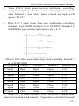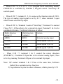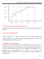
1
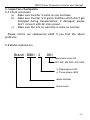
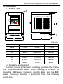
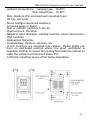
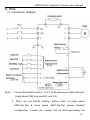
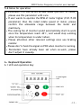
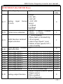
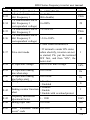
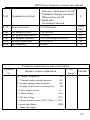
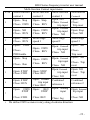
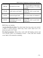
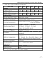
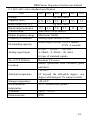
B801 Series frequency inverter user manual
B801 series Serv ice manual
1phase 220V-240V
0.5HP-3HP
3phase 220V-240V
1HP-10HP
3phase 380V-440V
1HP-10HP
Version:1.31
-1-
B801 Series frequency inverter user manual
Category
1. Preface ....................................................................... 3
2. Notes for safe operation................................................... 3
3. Inspection checkpoints
3.1 Check procedure............................................ … … .4
3.2 Model explanation ............................................... 4
4. Installation
4.1 Exterior size ...................................................... 5
4.2 Operating environment ......................................... 6
4.3 Notice ............................................................. 7
5. Wiring
5.1 Connection diagram .............................................. 8
5.2 Notes for operation............................................... 9
6. Keyboard Operation
6.1 LCD and operation key ........................................... 9
6.2 Utility of operation key .......................................... 10
7. Test run operation .......................................................... 10
7.1 Master some relevant functions which may let you
acquire more ideal use effects .................................. 10
7.2 Keyboard operation mode ....................................... 11
7.3 Keyboard operation for FOR/REV............................... 11
7.4 Terminal control mode ........................................... 13
7.5 Parameter resume ex-work value .............................. 13
7.6 Saving condition after parameter modification .............. 14
8. The symbol explanation on LCD .......................................... 15
9. Parameter and data sheet
9.1 Parameter list ..................................................... 15
9.2 Parameter explanation........................................... 21
10. Fault diagnosis and corrective actions
10.1 Notes for remedy once fault detects .......................... 28
10.2 Troubleshooting ................................................... 29
10.3 Notes during operation........................................... 30
11. B800-200V series standard specification .............................. 31
12. B800-400V series standard specification .............................. 32
-2-
B801 Series frequency inverter user manual
1. Preface
Thanks for your choose B801 series high functional frequency
inverter, please read this manual carefully before use.
2. Notes for safe operation
Frequency inverter is a latest product for electric and
electronic. To guard your safety, there are signals both “danger”
and “notice” in this manual to remind you some safety
precaution notices when movement, installation, operation and
check.
! DANGER
Misuse may cause casualty.
! NOTICE
Misuse may cause damage to inverter or system.
!
DANGER
•Please don’t take down, alter! Otherwise, it may cause
electric shock, fire and injure.
•Don’t open the cover during electrify
•Don’t put or insert wire, stick and filament etc. into
inverter to avoid short circuit or electric shock.
•Please don’t splash water or other liquid onto inverter.
!
NOTICE
•Please don’t perform a withstand voltage testing to the
components of inverter.
•Absolutely don’t connect output terminal (U, V, W) with AC
main circuit power supply.
•Components CMOS IC on circuit board are easily affected
and damaged by static electricity, please don’t touch it
casually.
•Electromotor and inverter should fit to the matched AC
power; Otherwise, it may cause operate abnormality, even
burn.
-3-
B801 Series frequency inverter user manual
3. Inspection checkpoints
3.1 Check procedure
a) Make sure inverter is same as you purchase.
b) Make sure inverter is in good condition which don’t get
damaged during transportation; if damaged, please
don’t connect with AC main power.
c) Make sure the S/N on warranty is same as inverter.
Please inform our salesperson ASAP if you find the above
problems.
3.2 Model explanation
Brand - B801 – 2
001
Applicable motor HP
001-1HP, 002-2HP… 010-10HP
2: Single phase 220V
4: Three phases 400V
Model Number
Brand name
-4-
B801 Series frequency inverter user manual
4. Installation
4.1 Exterior Size
8 .8 .8 .8 .8 .8 .
Unit: mm
400V
200V
H
H1
W
W1
D
1~2HP
3-5HP
7~10HP
1~2HP
3-5HP
7~10HP
165mm
214mm
255mm
150mm
200mm
241mm
120mm
151mm
180mm
107mm
135mm
164mm
123mm
160mm
180mm
Φ
5mm
6mm
6mm
4.2 Operating environment
To ensure proper performance and long operation life, Follow
the recommendations below when choosing a location for
installing B800 series frequency inverter, Make sure the B801
series frequency inverter is protected from the following
conditions
-5-
B801 Series frequency inverter user manual
. Ambient temperature: hanging type, -10~45℃
Tank closed type, -10~40℃.
. Rain, Moisture (For enclosed wall-mounted type)
. Oil fog, salt spray
. Direct sunlight.(Avoid use outdoors)
. Corrosive gases or liquid
. Dust or metallic particles in the air.
. Physical shock, Vibration
. Magnetic noise (Example: welding machine, power devices etc)
. High humidity
. Radioactive materials
. Combustibles: thinners, solvents, etc.
. If few inverters are mounted into cabinet, Please kindly put
them on ventilated position where the good ventilation is
available. Further to mount the cooling fan inside the cabinet to
make the ambient environment under 45℃
. Sufficient mounting space within below stipulation
-6-
B801 Series frequency inverter user manual
4.3 Notice
!
Notice
•Please don’t hold the front cover when move, the right way
is to hold the heatsink of inverter so as to avoid falling
down which could injury person or damage inverter itself.
•Please mount inverter onto nonflammable materials like
metal and other else; please don’t mount it nearby
nonflammable materials to avoid fire.
•If few inverters are mounted into a controlling cabinet,
cooling fan must be mounted inside cabinet to ensure
temperature of cabinet inside is lower than 45℃ to avoid
overheat.
• Please cut off AC main power until LCD off prior to remove
keyboard.
• Carry on the wiring or check inside of AC drive only after
cut off main AC power supply 2 minutes later, Otherwise, it
may be electric-shocked
-7-
B801 Series frequency inverter user manual
5. Wire
5.1 Connection diagram
Note: 1. three phases 400V use R/L, S/N, T as AC main power input terminal,
Single phase 220V only uses R/L and S/N.
2. There are not inbuilt braking resistors both of single phase
220V/1hp-2hp & three phase 400V/1hp–2hp among standard
configuration. If need, pls. contact with us while purchasing, we
-8-
B801 Series frequency inverter user manual
should inbuilt it inside free.
3. B800 Series inverter default as keyboard control (F-13=3), it will
work after AC main power input
4. Default value between terminal 5 & 6 is analog voltage signal input
(short circuit socket put on the right side), when the analog signal
input is current signal (F-17=3,4,5), Pls. put the short circuit socket on
the left side.
-9-
B801 Series frequency inverter user manual
- 10 -
B801 Series frequency inverter user manual
5.2 Notes for operation
• Parameter F-01 can be set as Max.30000 rpm/Min. of motor,
please use this parameter with care.
• If user wants to operate the RPM of motor higher (F-01/F-09
parameter) than the rated rotate speed of motor, please
confirm the allowable range between the motor and
machinery.
• The cooling fan of inverter would automatically start to work
once the temperature reach 40℃, and would stop working
when its temperature is under indoor.
• Please attention other relevant settings once use braking
resistor.
• Please don’t check the signal on PCB when inverter is running.
• Parameters have already been set when ex-work, please
don’t adjust it casually.
6.Keyboard Operation
6.1 LCD and operation Key
- 11 -
B801 Series frequency inverter user manual
6.2 Utility for operation key
•When inverter ex-work, standard parameters are set as
default.
•Press “Enter” key
one second, then enter into
check/modify standard parameter group.
•Press
or
key to check the parameter group from F-01 to
F-52
•Press “Enter” key
again, which can read parameter value.
•Press
or
key, modify parameter value.
•Press “Enter” key
again, Back to parameter group.
•If press “Enter” key
more one second or standby more20
seconds,
Back to initial status prior to standard parameter group
modification
•If want to enter into extended menu access(F-16-F-52),set
F-15 to “10”,and press “Enter” key .
7. Test operation
7.1 Master some relevant functions which may help you acquire
more ideal use effects
•Maximum and minimum output frequency F-01&F-02.
The maximum and minimum speed limitations are set according
to actual individual requirements.
•Accelerate and decelerate parameter F-03&F-04.
If linear acceleration time and linear deceleration time too
short on some occasions, which may cause drive over-current
- 12 -
B801 Series frequency inverter user manual
and let drive trip, which cause motor stop working.
••Stop mode F-05.
When F-05=0, inverter would diminish motor’s speed according
to linear deceleration time we set.
If F-02≠0, when inverter start, motor would accelerate from
mini frequency we set (F-02), when inverter stops work, the
motor linear decelerate to ‘0’ and then stop work.
If user want the motor stops work automatically (inertia
stopping), please sets F-05 to 1.
•V/F curve select F-06.
General loading F-06=0.
Such as fan, water pump etc. which are belonging to variable
torque loading. Set F-06=1, which will reduce the energy
wastage when motor run at low speed.
• Motor rated current, rated frequency and rated RPM (F-08,
F-09, F-10).
Parameters should be set according to the nameplate on the
motor
• Low speed voltage compensation (F-12).
Favorable to start motor smoothly, Maximum value of voltage
compensation up to 28%.
• Controlling methods select (F-13).
Terminal controlling method is for long distance control use.
Keyboard controlling method is for trial running or handle
manually.
• “Extended menu access” select(F-16~F-52)
“Extended menu access” is designed for inverter application
experts, engineers or technicians. General users don’t need to
use it.
- 13 -
B801 Series frequency inverter user manual
7.2 Keyboard operation mode
•Press “Run” Key 1 ,LCD appear to H0.0.
•Press “UP” Key ,frequency output increase.
•Press “DOWN” Key
,frequency output descends.
•Press “STOP” Key 0 , inverter stop frequency output, LCD
appears to stop.
7.3 Forward/Reverse operation on Keyboard
•Set F-13=2.
•Press “RUN” Key 1 , LCD appears to H0.0.
•Press
key,Speed increase.
•Press “RUN” Key 1 again,Change motor rotary direction.
•Set Parameter F-13=3
•Press “RUN” Key 1 ,LCD appears to H***•*
•Turn the potentiometer as clockwise to increase speed
•Turn the potentiometer as anti-clockwise to descend speed
•Set Parameter F-13=4
•Press “RUN” Key 1 ,LCD appears to H***•*
•Turn the potentiometer as clockwise to increase speed
•Turn the potentiometer as anti-clockwise to descend speed
•Press “RUN” Key 1 again, Change motor rotary direction
- 14 -
B801 Series frequency inverter user manual
7.4 Terminal controlling operation mode
•Parameter F-13=0 (Control terminal operation mode)
• Connect the start/stop switcher among terminal 1,2 and 5.
• Connect one potentiometer (2.2KΩ ~10KΩ ) among terminal 5, 6
and 7
When F-20=0 means two-wire initialization controlling,
Terminal 1, 2 stand for Forward Start/Off switcher and Reverse
Start/Off switcher respectively.
• When “Start/Off” switcher ON, Turn potentiometer to change
output frequency (HZ) to make the motor rotary
• When “Start/Off” switcher OFF or turn potentiometer to “0”,
Inverter stop work
When F-20=1 means three-wire initialization controlling,
Terminal 1 stand for “Start” Switcher, Terminal 2 stand for
“For/Rev” switcher, Terminal 4 stand for “Stop” switcher.
7.5 Parameters resume default (Parameters reset)
•When inverter stop and appear “Stop” on LCD, simultaneity
press ,
and “Enter” Key 0 1 second
•LCD appears P-SET, which means all parameters have resumed
to default (ex-work value).
•Press “Enter” Key 0 again, LCD appears “Stop”.
•Parameter F-45 would restore to 10, but F-47 and F-14 not be
effected.
- 15 -
B801 Series frequency inverter user manual
7.6 The saving condition after parameter modification
•As F-46=0 (Default value), all parameters could be modified,
and they would be saved in EEPROM when AC main power is cut
off.
•As F-46=1, all parameters could be modified, but they would
not be saved in when AC main power is cut off.
•As F-46=2, all parameters couldn’t be modified, read only.
Notice
To prevent other persons modify parameters causally, please
select any number among 0 to 3999 for parameters F-45 (enter
into “Extended menu access” password).
•Under status of “Extended menu access (monitor)”,LCD would
return to initial status if without any operation within 20
seconds.
•when enter into the status of monitor, LCD would return to
initial status if without any operation over 60 seconds.
• Press
Enter Key over 1 second, we can switch the status
between monitor mode and Parameter F-01, when we switch to
monitor mode, we can use UP
and DOWN
Key to read the
relevant parameter contents
- 16 -
B801 Series frequency inverter user manual
8. The symbol explanation on LCD
Symbol
on LCD
H50.00
L50.00
P50.00
F50.00
A4.5
U300
Radix
Point
twinkling
Symbol
on LCD
d 300
Explanation
Frequency output 50HZ
Remote control terminal
set frequency 50.00Hz
Keypad potentiometer
set frequency 50.00
Keypad Up and down
key set frequency 50.00
Output current 4.5A
Motor
output
voltage
300VAC
Drive overload
Parameter and datasheet
9.1 Parameter list
STANDARD PARAMETER
Par.
Description
F-01 Maximum speed
F-02 Minimum speed
F-03 Linear Accel time(s)
F-04 Linear Decel time(s)
t 345
Explanation
DC bus voltage 300VDC
Interior thermal
resistor value
n 1350
RPM 1350
r 1.05
Motor slip 1.05Hz
Stop
Drive stop work
F-01
Parameter F-01
P-SET
Resume default value
9.
Range
F-02 to 500Hz
0 to F-01 (max 500Hz)
0.1 to 3,000s
0.1 to 3,000s
Default
50Hz
0Hz
5s
5s
- 17 -
F-05
F-06
F-07
F-08
F-09
F-10
F-11
F-12
F-13
F-14
F-15
B801 Series frequency inverter user manual
0, 2: linear stop (ramp stop)
Stop mode select
0
1: inertia stop (coast to stop)
0: Constant torque,
V/F characteristic
0
1: Variable torque
Rapid linear Decel time 0.0 to 25s.
1.0s
(s) when power cut off
(Disabled when 0.0s)
Motor rated current
Motor rated current * (10% to
100%
100%)
Motor rated frequency
0Hz to 500Hz
50 Hz
Motor output voltage
0-100% of motor rated output
90%
voltage
Motor pole pairs
0,1,2,3,4,5
2
Voltage boost
0 to 28% of max output voltage 6%
0: Terminal control
1: keyboard control-Fwd only
,
control speed
2: keyboard control-Fwd/Rev
,
control speed
3: keyboard control-Fwd only
Potentiometer control speed
Terminal or Keypad
4: keyboard control-Fwd/Rev
3
control select
Potentiometer control speed
5: Reserve(Modbus RS485 )
6: Potentiometer control speed,
Terminal control Start/Stop
7.
,
control speed
Terminal control Start/Stop
8. Terminal control speed
Keyboard control Start/Stop
Read
Trip log
Last four trips stored
only
Extended menu access
Code 0 to 3999
0
- 18 -
B801 Series frequency inverter user manual
EXTENDED PARAMETER Menu
F-16
Drive Capacity
0~13
F-20
Voltage:
0: 0V-10V,
1: 10V-0V
Analog input format 2: -10V-10V
(V/mA)
Current:
3: 4-20mA
4: 0-20mA
5:20-4mA
0:2KHz 1:4KHz 2:8KHz
Carrier wave selection 3:12KHz 4:15KHz
0: Drive enabled
1: Drive fault or External trip
Multi-function terminal 2: At set speed
output selection
3: motor stop (Speed =zero)
4: Motor at max speed (F-01)
5: motor healthy
Multi-function terminal 0 to 7
input selection
F-21
F-22
F-23
F-24
F-25
F-26
F-27
F-28
F-29
Multi-stage speed 1
Multi-stage speed 2
Multi-stage speed 3
Multi-stage speed 4
Multi-stage speed 5
Multi-stage speed 6
Multi-stage speed 7
Multi-stage speed 8
Slip compensation
F-30
Analog output function
F-17
F-18
F-19
-F-01 (reverse) to F-01(Forward)
-F-01 (reverse) to F-01(Forward)
-F-01 (reverse) to F-01(Forward)
-F-01 (reverse) to F-01(Forward)
-F-01 (reverse) to F-01(Forward)
-F-01 (reverse) to F-01(Forward)
-F-01 (reverse) to F-01(Forward)
-F-01 (reverse) to F-01(Forward)
0% to 110% of rated Slip
0:output frequency(motor speed)
1:Ouput current
2:Drive enabled
3:Given frequency
Read
only
0
1
1
0
5.0Hz
0.0Hz
0.0Hz
0.0Hz
0.0Hz
0.0Hz
0.0Hz
0.0Hz
0%
0
- 19 -
F-31
F-32
F-33
F-34
F-35
F-36
B801 Series frequency inverter user manual
Skip freq /speed
0 to F-01 (max)
0Hz
Skip freq /speed band
(0 –100%)* F-09
0Hz
V/F characteristic curve 0 to F-09
15Hz
Mid. Frequency 1
(0Hz disable)
V/F characteristic curve
Mid. Frequency 1
0 to100%
29
(correspondent voltage)
V/F characteristic curve F-33 to F-09
25Hz
Mid. Frequency 2
V/F characteristic curve
Mid. Frequency 2
F-34 to 100%
42
(correspondent voltage)
0: Start when terminal ON
F-37
Drive start mode
F-38
DC injection voltage
F-39
DC injection braking
time when stop
DC injection braking
time before start
DC injection select
F-40
F-41
F-42
F-43
F-44
F-45
1: If termnal is under ON status
before electrify, inverter can not
be started; Pls. put the terminal
OFF first, and then “ON”, the
motor start.
0 to 22% of max voltage
0 to 250.0s
0 to 250.0s
0: Inactive
1: Enabled
0: Disable
Braking resistor function
1: Enable
select
2: Enable with overload protect
Frequency instruction
0 –1100
adjustment factor
Analog input bias
0 to 1000
Enter “Extended menu 0 to 3999
access”code
1
16%
0s
0s
0
1
1065
180
10
- 20 -
F-46
F-47
F-48
F-49
F-50
F-51
F-52
B801 Series frequency inverter user manual
0: Parameters can be changed,
auto-save when power cut off
1: Parameter changes not saved
Parameter access lock
0
When power cut off
2: Read-only.
No changes allowed.
Read
Hours run meter
0 to 9999 hours
only
PID samples cycle
0.1S-400.0S
0.2
PID proportional factor 0.1-400.0
0.1
PID integral constant
1-3999(0 integral disable)
100
Analog output gain
0% to 500%
90
Jog frequency
0-50Hz
10
Parameter explanation to only-read window
Parameter
No.
Set
Monitor content explanation
Range
H: output frequency
L: Terminal analog setting frequency
HZ
P: Keypad analog setting frequency
HZ
Default
HZ
F: Keypad Up & Down key setting freq.
HZ
A: Drive output current
A
U: Motor Voltage
VAC
d: DC bus voltage
VDC
t: Interior thermal resistor (NTC) Value 0~1023
n: motor rpm display
RPM
r: Motor slip display
- 21 -
B801 Series frequency inverter user manual
F-20
0
1
2
3
Multi-function Contact input menu
Multi-function Multi-function Multi-function
contact 1
contact 2
contact 3
Open: NO
Open:Stop
Open:Stop
Close:External
Close:FWD
Close:REV
trip input
Open:External
Open:FWD
Open:NO
trip input
Close:REV
Close:RUN
Close:NO
Multi-stage
Open:STOP Multi-stage
Close:RUN
speed 1
speed 2
Open: STOP
Open: External
Open:FWD
trip input
Close:
Close:REV
Close:NO
PID Enable
Multi-function
Contact 4
Open:NO
Close:
Trip reset
Open: Stop
Close: NO
Multi-stage
speed 3
Open:NO
Close:
Trip reset
Open:NO
Close:Run
Open:FWD
Close:REV
Open:External
trip input
Close:NO
5
Open: STOP
Close: FWD
Open: STOP
Close: REV
Open: External
trip input
Close: NO
Open: NO
Close: Trip
reset
6
Open: STOP
Close: RUN
Open: External
trip input
Close: REV
Combined
reference 1
Combined
reference 2
Open:
Open:
Open: Analog
input
Open: External
trip input
Open:Stop
4
7
FWD
STOP
Close: FWD
REV
STOP
Close:Trip
reset
Close: REV
Close: NO
Close: Jog
• We define FWD as motor rotary along clockwise direction
- 22 -
B801 Series frequency inverter user manual
• When F-20=0 which means two-wire initialization controlling,
analog input signal specification can be set through parameter F-17.
when Terminal 3 close which means external trip input, LCD
appears “IN-Fit”.
• When F-20=1 which means three wires initialization controlling,
Terminal 1 is for START, Terminal 2 is for FWD/REV, Terminal 4 is
for STOP, the type of analog input signal is set by F-17
•When F-20=2 which means multi-stage speed controlling, Terminal 1
is for START/STOP
Preset speed
Terminal 2
Terminal 3
Terminal 4
Speed given
1st Speed
Open
Open
Open
F-21
2nd Speed
Close
Open
Open
F-22
3rd Speed
Open
Close
Open
F-23
4th Speed
Close
Close
Open
F-24
5th Speed
Open
Open
Close
F-25
6th Speed
Close
Open
Close
F-26
7th Speed
Open
Close
Close
F-27
th
8 Speed
Close
Close
Close
F-28
• When F-20 =3,Contact terminal 1 is for PID control, Feedback value
input from terminal 6 and terminal 5, Target value is set from the keypad
- 23 -
B801 Series frequency inverter user manual
• When F-20 =4, if F-13=1, 2,3,4 (Keypad local controlling mode),
FWD/REV is controlled by terminal 2, Keypad control “Start/Stop”&
control speed.
• When F-20 =5, terminal 1, 2, 4 is same as the function when F-20=0,
The type of analog input signal is set by F-17, when terminal 3 open
which means external trip input.
• When F-20 =6, Terminal 1 control “Start/Stop”; Terminal 2 is normal
Close (N.C), if Open that is for external trip input; Terminal 3 & 4 is for
combined reference, Combined reference as below:
Multi-function
Multi-function
Action
contact 3
Contact 4
OPEN
OPEN
External analog input
CLOSE
OPEN
Multi-speed 5 (F-25)
OPEN
CLOSE
Multi-speed 4 (F-24)
CLOSE
CLOSE
Multi-speed 7 (F-27)
• When F-20 =7, terminal 1 & 2 control the rotary direction
(FWD/REV); if terminal 3 Open that is for external analog input, Close
is for Jog running; Terminal 4 Open is for external trip input.
Note: 1)If contact terminal 1 & 2 Close at the same time, Software
default it as operation error--Inaction.
2) Jog reference is prior to other references, which given by F-52
- 24 -
B801 Series frequency inverter user manual
9.2 Parameter explanation
Standard parameter group
•F-01 max output frequency
Maximum frequency limitation
•F-02 min output frequency
Minimum frequency limitation
•F-03 linear Accel time(S).
The required time accelerate from 0HZ to 50HZ.
•F-04 linear Decel time(S).
The required time decelerate from 50HZ to 0HZ
•F-05 stop mode select
0: Decelerate and stop according to parameter F-04;
2: Decelerate and stop according to parameter F-07;
1: Get “Stop”instruction, Drive stop output.
motor coast to stop(inertially).
•F-06 V/F characteristic curve select.
(A) Relation between voltage and frequency.
Pls.refer to picture: 0 curve is constant torque,
1 curve is variable torque.
(B)Through adjust the parameter F-33,F-34,F-35,F-36,V/F curve can be
further changed as below picture
- 25 -
B801 Series frequency inverter user manual
•F-07 Decelerate time when power cut off.
Linear deceleration time (F-05=2) when AC main power cut off. (Refer
to F-07).
•F-08 motor rated current
Motor rated current = Drive rated current * (10%-100%). When the
capacity of drive is over motor capacity, properly adjust Parameter F-08
can avoid motor run with overload
•F-09 motor rated frequency.
The rated current value marks on the nameplate of motor, Pls. input the
parameter as per motor rated frequency on the nameplate; Otherwise, it
maybe cause both motor and AC drive damaged. if parameter F-09 be
changed, pls. reset parameter F-33 and F-35 to make sure
F-09>F-35>F-33; Otherwise, AC drive parameter would be resumed to
default value
- 26 -
B801 Series frequency inverter user manual
•F-10 motor output rated voltage
Correspondence output voltage of rated RPM (%). If Parameter F-10 be
change, pls. reset parameter F-36.F-34.F-12 to make sure F-10>
F-36>F-34>F-12.
Note: when the parameters we set do not satisfy with the above
relationship, AC drive parameter would be resumed to default value
•F-11 Motor pole pairs
For example: Motor rated frequency is 50HZ, RPM range can be set
from 600-3000RPM/min. It just for display the RPM used.
When F-11≠ 0, LCD show the speed with RPM unit, otherwises, LCD
display “0”
•F-12 Low speed voltage compensation (boost).
Application of compensation function make frequency inverter get
adjustment compensation when low speed runs, thus ensure the motor
start steadily.
•F-13 Terminal or keyboard controlling select (controlling mode)
Set motor Start/Stop controlling via terminal or keypad.
Set frequency reference controlling via terminal or keypad
When F-13=0, both “Start/Stop” and frequency reference come from
terminal controlling, (Pls. refer to F-20)
When F-13=2, Control speed via UP
or DOWN ,
Repeat press “Run”Key 1 to achieve FWD/REV functions
Press “STOP”Key 0 , and then Press “Run”Key 1
Drive start to make motor still run as FWD direction.
- 27 -
B801 Series frequency inverter user manual
When F-13=4, Control speed via the potentiometer on the keypad
Press “Run”Key 1 to start motor and achieve FWD/REV function.
When F-13=6, Control speed via the potentiometer on the keypad
Control START/STOP via terminal controlling,
If F-20=0 means two-wire system controlling,
If F-20=1 means three-wire system controlling,
If F-20=2,3,4, Parameter disable
When F-13=8, Control speed via terminal
Control Start/Stop via keypad
•F-14 Trip log record.
The previous 4 trips records can be stored according time in sequence,
the earliest appearance record is recent trip record.
Press
or
key, 4 records are alternative.
•F-15 Enter “extended menu access”menu.
Input default “10”to enter into “extended menu access”, this default can
be modified through parameter F-45.
Forbid non-authorization entering into “Expansion Menu access”.
Expansion parameter group
•F-16 Drive capacity
Read only.
•F-17 Input analog signal format
Input analog voltage/current signal through terminal 6, which be
regarded as external frequency given signal.
When analog input is current signal, pls. put the SC socket on left side
CPU board (Pls. refer to Page 8--connection diagram)
- 28 -
B801 Series frequency inverter user manual
If bipolar signal set as -10~10V & F-13=0, frequency inverter run
FWD/REV is controlled by polarity signal
•F-18 Carrier wave frequency selection.
Effective power stage switching frequency inverter. Improvements in
acoustic noise and output current waveform occur with increasing
switching frequency at the expense of increased losses within the drive
0: 2 KHz, 1:4 KHz, 2:8 KHz, 3:12 KHz, 4:15KHz
•F-19 Multi-function contact output selection.
Relay contact output “ON/OFF”function indicate the working status of
drive
•F-20 Multi-functions contact input selection.
Multi-functions terminal 1, 2, 3 and 4 correspondence common
terminals to effect ON/OFF functions, the definition please refer to F-20
multi-functions contact input menu.
•F-21~F-28 multi-stages speed 1~8.
Refer to multi-functions contact input (F-20), Preset multi-speed 1~8
according to actual running requirement
•F-29 Slip compensation
Slip modification factor, whose numerical definition is applied as
interior calculation for slip compensation percentage.
- 29 -
B801 Series frequency inverter user manual
•F-30 Analog output functions.
The terminal 8(-), 9(+) is the multi-function analog output terminal.
As F-30=0, output 10V=F-01 *100% correspondence actual output
frequency.
As F-30=1, output 5V=F-08 *100%, Correspondence motor currents
As F-30=2, Give a digital output
As F-30=3, output 10V=F-01 *100% correspondence set frequency
•F-31 Skip frequency/speed.
Skip frequency center controlling points are defined by F-31, when the
frequency is negative (-), F-32 appear to 0.
- 30 -
B801 Series frequency inverter user manual
•F-32 skip frequency/speed band.
The center is defined by F-31.
•F-33 V/F Characteristic Curve Mid. Frequency 1
Pls. refer to V/F curve picture
•F-34 V/F Characteristic Curve Mid. Frequency 1
Correspondence output voltage
Pls. refer to V/F curve picture
•F-35 V/F Characteristic Curve Mid. Frequency 2
Pls. refer to V/F curve picture
•F-36 V/F Characteristic Curve Mid. Frequency 2
Correspondence output voltage
Pls. refer to V/F curve picture
•F-37 Starting mode.
(A) When F-37 =1, If terminal 1 & 5 is “ON”before electrify, drive can
not be started. Pls. put the terminal 1& 5 “OFF”first, and then put
terminal 1 & 5 “ON”, the motor start.
(B)When F-37=0, Drive will run when terminal 1& 5 “ON”
•F-38 DC injection voltage
If F-05 selection is “ramp to stop”, F-38 sets the level of DC braking
applied when the ramp reach zero
•F-39 DC injection braking time
If F-05 selection is “ramp to stop”, F-39 sets the duration of DC braking
applied when the ramp reaches zero
- 31 -
B801 Series frequency inverter user manual
•F-40 DC injection braking time before start
•F-41 DC injection function
As F-41=1, if drive is on working, the DC injection functions enable and
will execute according to parameter F-39 & F-40
•F-42 Braking resistor function select
Activate interior brake resistor.
When F-42=1, Brake resistor functions enable.
When F-42=2, Should be overload protection to avoid resistor and drive
damaged
•F-43 Frequency instruction adjustment factor.
Scales the analog signal (Voltage/Current) input at control terminal 6 &
output frequency.
Appear the correspondence analog input
value according to parameter F-01.
F-43
The analog input default is +10V
correspondence F-01 which is the
absolute value of input gain
(Pls. see the picture)
F-44
0V
10V
•F-44 Analog input Bias
This Parameter is used for compensation of frequency reference bias,
Pls. refer F-43
•F-45 Enter “Extended menu access”code
Define the password for “Extended menu access”(F-15)
- 32 -
B801 Series frequency inverter user manual
•F-46 Parameter access lock
Controls user access to parameters.
When F-46=0, all parameters can be changed and these changes will
be stored automatically. When
When F-46=1, changes may be made, but these will not be stored
when the drive power cut off.
When P-46=2, Parameters are locked and cannot be changed thus
preventing unauthorized access
•F-47 Accumulation running time (Hours run meter)
Read only.
•F-48 PID control samples cycle
•F-49 PID control proportional factor
•F-50 PID control integral constant
When F-20=3, Drive output frequency is decided by PID close-loop
controller. PID parameter can be set via “Up”
and “Down” key
on the keypad (Full range value is equal to value of F-01; For example,If
F-01=50, the full range is 50.00)
Unit (PID) is decided according to physical circumstance, If PID set
value is for water pressure, 10.00 should be regarded as 10.00Mpa.
The feedback of PID controller input from Terminal 6, Analog input
format & type is decided by F-17 & F-43
•F-51 Analog output gain
As adjustment of analog output voltage standard, if the maximum output
voltage is less than 10V, it is necessary to reduce the parameter value of
F-51
- 33 -
B801 Series frequency inverter user manual
•F-52 Jog Running
When F-20 = 7, Jog reference is prior to other references, which given
by F-52
- 34 -
B801 Series frequency inverter user manual
10. Fault diagnosis and corrective actions
10.1 Notes for remedy once fault detects.
•If want to eliminate abnormity, must clean up the abnormity
conditions and withdraw controlling terminal order, then press 0
(“STOP” key) to reset, drive would start automatically,(re-start
automatically according to parameter F-37.)
•If motor stop and inverter appear “Stop”, which mean drive is
Non-abnormity, it’s under standby.
10.2 TROUBLESHOOTING
Fault
What has happened
Code
P-SET
Default
loaded
parameters
O-C
Over current on drive
output.
Drive output current
exceed OC level
O-Volt
Over voltage on DC bus
U-Volt
Under voltage on DC
bus
OC-brt
OL-trp
PS-Flt
Brake resistor short
circuit.
Overload
150% current >1 min.
Internal power module
fault.
What to do
Press STOP key to
acknowledge and enter
parameter values.
1.Check motor coil resistance
2.Extend the accel/decal time
3.Check motor insulation
4.Multi-meter check
1.Extend the deceleration time
2. Fit braking controller and
braking resistor
3.Check input voltage
1.Main circuit DC voltage is
lower than detected voltage.
2.check power voltage & wire.
1.Check cable
2.Check braking resistor
1.Check motor loading and
reduce loading
Pls. contact your local
Distributor
- 35 -
OH-trp
UN-Flt
B801 Series frequency inverter user manual
1.Check heatsink fan
2. Check ambient temperature.
Heatsink over-heat
3. Additional space or cooling
needed?
Try again.
If not, Pls. refer to your local
Fault source not found
distributor.
IN-Flt
External input fault
Pls. check status of terminal 3
EE-Flt
EEPROM fault.
Parameters not saved,
Keep default
Try again.
If not, Pls. refer to your local
distributor.
10.3 Notice on running
Acceleration/deceleration: Too short ramp time may cause over current
(>150% or rated current), which may cause accel/ decel not to be
achieved, and/ or O-C fault.
Overload protection: When drive work with full loading current and
over current (150% of overloading current > 1min.).the drive should
occur fault, LCD should be twinkling.
- 36 -
B801 Series frequency inverter user manual
11-1. B801-200V series standard specification
B801 series
Voltage
Capacity (KW)
Rated output vol. (V)
Rated output current A
Control mode
Output frequency range
Frequency resolution
Overloading capacity
Analog signal input
No. of V/F Patterns
Location
Ambient temperature
2001
2002
2003
2005
2007
2010
1or 3φ200V-240V
3φ200V-240V
0.75 1.5
2.2
3.7
5.5
7.5
3φ220V-240V
4.3
7.0 10.5
14
19.6 26.6
Sine wave PWM control
Maximum 500Hz
Analog input volume: 0.1Hz
Rated output current 150%-1 minute
175% -2 seconds.
0~10V, 10~0V, -10~10V,
4~20mA,0~20mA,20~4mA
6 types of standard signals.
Random V/F curve.
Indoor (protected from corrosive gases
and dust)
-10~40℃
(If beyond the allowable degree, one
degree will derogate 5% output current).
-40~60℃
95%(without dew gather)
Storage temperature
Environmental
temperature
Vibration
2M/S2(0.2G)
Protection rate
IP20
*** 0.37kw & 0.55kw also are available.
- 37 -
B800 Series frequency inverter user manual
11-2. B801-400V series standard specification
B801
Voltage
Capacity (KW)
Rated output vol. (V)
Rated output current A
Control mode
Output frequency range
Frequency resolution
Overloading capacity
Analog signal input
No. of V/F Patterns
Location
Ambient temperature
Storage temperature
Environmental
temperature
Vibration
Protection rate
4001
4002
4003
4005
4007
4010
3φ380V-440V
2.2
3.7
5.5
7.5
3φ380V-440V
2.2
4.1
5.8
9.5
13
16
Sine wave PWM control
Maximum 500Hz
Analog input volume: 0.1Hz
Rated output current 150%-1 minute
175% -2 seconds.
0~10V, 10~0V, -10~10V,
4~20mA,0~20mA,20~4mA
6 types of standard signals.
Random V/F curve.
Indoor (protected from corrosive gases
and dust)
-10~40℃
(If beyond the allowable degree, one
degree will derogate 5% output current).
-40~60℃
95%(without dew gather)
0.75
1.5
2M/S2(0.2G)
IP20
- 34 -
B801 Series frequency inverter user manual
B801 Series Frequency inverter
AGENT: