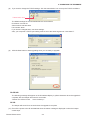
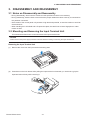
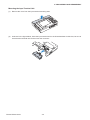
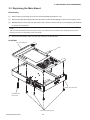
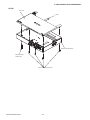
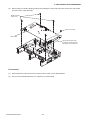
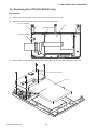
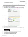
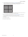
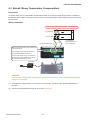
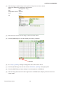
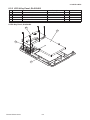
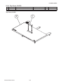
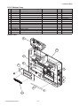
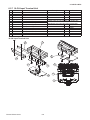
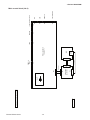
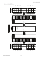
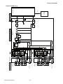
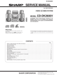
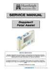
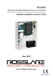
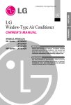
1
midi LOGGER
450/400/350
GL400-UM-251
SERVICE MANUAL
GL400-UM-251-13-9370
HISTORY OF REVISIONS
No. Date issued
1
04.06.01
2
04.08.10
3
04.10.15
4
04.10.15
5
04.10.22
6
04.10.28
7
05.03.22
8
05.06.30
9
05.10.17
10
05.12.01
11 06.03.03
12 06.03.07
13 06.09.13
14 07.03.29
GL400-UM-251-9370
Description of revision
First Printing
Quantity of the LCD and the inverter corrected.
Part number for the input terminal units added.
50-Ch terminal unit information added
Some page couldn't open. It corrected.
Some problem in the PDF file. It corrected.
Note was added for upgrading the firmware.
GL450 information added.
Part number for the main board of GL400/350 corrected.
Part number for the AC power cables added.
Part number for the mainboard of GL450 corrected.
Part number for the battery Cover of GL400 corrected.
The remark for the terminal board and the terminal relay board added.
Part number for the bottom case 450 added.
i
Page
All
6-1
6-1
4-5,4-7,5-2,5-7,5-8
3-1
All
2-4
All
6-1,6-6
6-9
6-1,6-6
6-7
6-8,6-9
6-7
Edition
01
02
03
03
04
05
06
07
08
09
10
11
12
13
TO ENSURE SAFETY
This Service Manual has been compiled for the purpose of facilitating repair and maintenance of the
GL450/400/350 midi LOGGER by Graphtec service personnel and other persons who have undergone
equivalent technical training.
Maintenance or repair by unauthorized service personnel is to be strictly avoided. Because the
GL450/400/350 contains numerous internal components with a high electric potential, such work by
unauthorized service personnel could cause human injury or serious damage to the GL450/400/350 midi
LOGGER.
GL400-UM-251-9370
ii
CONTENTS
1. CONFIGURATION .................................................................................. 1-1
1.1 Model Configuration ................................................................................................... 1-1
1.2 Accessories and Options ........................................................................................... 1-1
2. UPGRADING THE FIRMWARE ............................................................. 2-1
2.1 How to Upgrade the GL450/400/350 Flash ROM from the PCMCIA Card .............. 2-1
2.2 How to Upgrade the GL400/350 Flash ROM from the TCP/IP Port ......................... 2-2
3. DISASSEMBLY AND REASSEMBLY .................................................... 3-1
3.1
3.2
3.3
3.4
3.5
Notes on Disassembly and Reassembly .................................................................. 3-1
Mounting and Removing the Input Terminal Unit .................................................... 3-1
Replacing the Main Board ..........................................................................................3-3
Replacing the AMP Board ..........................................................................................3-6
Replacing the LCD (GL450/400 only) ........................................................................3-9
4. SETUP PROCEDURES.......................................................................... 4-1
4.1
4.2
4.3
4.4
Entering the System Setup Menu .............................................................................. 4-1
Setting Up Setup1 (Voltage Input) ............................................................................. 4-2
Setup2 (Room Temperature Compensation) ............................................................4-5
Setting Up Setup3 (RTD Temp.) .................................................................................4-8
5. INSPECTION AND CHECK PROCEDURES ......................................... 5-1
5.1 Insulation Resistance ................................................................................................. 5-1
5.2 Inspection and Check Methods ................................................................................. 5-2
5.2.1 Measurement Accuracy ........................................................................................................ 5-4
5.2.2 Temperature Accuracy ...........................................................................................................5-7
5.2.3 RTD Accuracy ....................................................................................................................... 5-9
5.3 Signal-to-Noise Ratio ................................................................................................ 5-10
6. PARTS LISTS ......................................................................................... 6-1
6.1 Recommended Parts List ........................................................................................... 6-1
6.2 Parts Lists .................................................................................................................... 6-2
6.2.1
6.2.2
6.2.3
6.2.4
6.2.5
6.2.6
6.2.7
6.2.8
6.2.9
Top Cover, GL450/400.......................................................................................................... 6-2
LCD & Key Panel, GL450/400 .............................................................................................. 6-3
Top Cover, Reverse Side, GL450/400 .................................................................................. 6-4
Top Cover, GL350 ................................................................................................................. 6-5
Main Frame ........................................................................................................................... 6-6
Bottom Case ..........................................................................................................................6-7
10-CH Input Terminal Unit .................................................................................................... 6-8
20-CH Input Terminal Unit .................................................................................................... 6-9
AC Adapter ............................................................................................................................ 6-9
7. Block Diagram ....................................................................................... 7-1
7.2 Block Diagram ............................................................................................................. 7-1
7.2 Wirring Diagram .......................................................................................................... 7-2
GL400-UM-251-9370
iii
GL400-UM-251-9370
iv
1. CONFIGURATION
1. CONFIGURATION
1.1 Model Configuration
GL450
GL400
GL350
: 10-channel model with color monitor and internal memory (Replaced model from the
GL400/350)
: 10-channel model with color monitor and internal memory
: 10-channel model with internal memory
1.2 Accessories and Options
GL400/350
Model
name
10 channels/terminal unit
10SU
20 channels/terminal unit
20SU
50 channels/terminal unit
50SU
Battery Pack
B-511
Battery Charger
B-512
Logic Alarm Cable
B-513
DC Drive Cable
B-514
Cable to connect main units together B-515
Unit name
Description
10 channels/unit (2 units mountable for a maximum of 20 channels)
20 channels/unit (2 units mountable for a maximum of 40 channels)
50 channels/unit (2 units mountable for a maximum of 100 channels)
GL450
Model
name
10 channels/terminal unit
10TU
20 channels/terminal unit
20TU
50 channels/terminal unit
50TU
Humidity Sensor
B-530
Battery Pack
B-517
Logic Alarm Cable
B-513
DC Drive Cable
B-514
Cable to connect main units together B-515
Unit name
GL400-UM-251-9370
Description
10 channels/unit (2 units mountable for a maximum of 20 channels)
20 channels/unit (2 units mountable for a maximum of 40 channels)
50 channels/unit (2 units mountable for a maximum of 100 channels)
Same as GL500
Same as GL400/350
Same as GL400/350
Same as GL400/350
1-1
1. CONFIGURATION
GL400-UM-251-9370
1-2
2. UPGRADING THE FIRMWARE
2. UPGRADING THE FIRMWARE
The version of your GL450/400/350’s firmware can be upgraded by rewriting the flash ROM on the pertinent
circuit boards using a choice of methods. You can upgrade the firmware by loading the update program from
either a personal computer via the TCP/IP port or from a PCMCIA card.
2.1 How to Upgrade the GL450/400/350 Flash ROM from the PCMCIA Card
Preparations for the upgrade
Firmware :Mxxxa001.G40 ← Main Program file for GL450/400/350
:Mxxxa002.G40 ← Main Program file for GL450/400/350
Use from version 2.0 to the GL450.
Do not use latest version 2.0 to the GL400/350.
(1)
Connect the AC adapter for the GL450/400/350.
(2)
Turn on the GL450/400 and then adjust the monitor contrast using the monitor control dial when you are
going to upgrade the GL450/400.
Turn off the GL450/400 after adjust the monitor contrast.
(3)
Copy the two main program files to a PCMCIA card from the computer.
How to upgrade
(1)
Insert the PCMCIA card containing the main upgrade program into the GL450/400/350's PCMCIA card
slot.
(2)
Turn on the GL450/400/350 to automatically execute the upgrade program.
(3)
Wait until the display shown below appears or until the beeper sound stops.
Note:
Don't turn off the GL450, GL400 or the GL350 until this process is finished.
GL400
The following message will appear on the GL400 display in yellow characters when the upgrade is
complete. Also the beeper will sound for 5 seconds.
“Please Turn Off the Power. I have locked up.”
Note:
Adjust the the monitor contrast using the monitor control dial when the above message will not appear
on the GL450/400.
GL350
The beeper will sound for 5 seconds when the upgrade is complete.
(4)
Turn off the power to the GL450/400/350 when the above message is displayed or when the beeper
sound stops.
(5)
Delete the two main program files in a PCMCIA card from the computer.
This is avoiding to upgrade by mistake.
GL400-UM-251-9370
2-1
2. UPGRADING THE FIRMWARE
2.2 How to Upgrade the GL400/350 Flash ROM from the TCP/IP Port
Preparations for the upgrade
(1)
Connect the AC adapter for the GL450/400/350.
(2)
Connect the LAN cable for the GL450/400/350 and PC. (If you connect P to P, use a cross LAN cable. If
you connect with a hub, use a parallel LAN Cable.)
How to upgrade
OS
Software
:Windows 2000/XP
:GL40upd.exe ← Upgrade software file
:xxx.dll
← Upgrade software dll file
Firmware :Mxxxa001.G40 ← Main Program file for GL450/400/350
:Mxxxa002.G40 ← Main Program file for GL450/400/350
Use from version 2.0 to the GL450.
Do not use latest version 2.0 to the GL400/350.
(1)
Copy the two upgrade software files to the same directory in the PC.
(2)
Turn on the power switch of the GL450/400/350.
(3)
Execute GL40upd.exe.
(4)
Display the menu as shown below.
Exit program Icon
Open File Icon
Transmission Icon
GL400-UM-251-9370
2-2
2. UPGRADING THE FIRMWARE
(5)
Click the Open File icon to show the menu as below.
Open File Icon
(6)
Select the main update file as ”Mxxxa001.G40.
(7)
Click the Open Button.
GL400-UM-251-9370
2-3
2. UPGRADING THE FIRMWARE
(8)
If you need to change the TCP/IP settings, click the transmission icon to set up the TCP/IP conditions.
Transmission Icon
The default settings for the GL450/400/350 are set as follows.
IP Address: 192.168.0.1
Subnet mask: 255.255.255.0
Port number: 8023
If you haven’t changed them, use these settings.
Also, your computer’s TCP/IP port setting must be set to the same segment as “192.168.0.X”.
(9)
Click the Start button to start upgrading when you are ready to upgrade.
GL450/400
The following message will appear on the GL450/400 display in yellow characters when the upgrade is
complete. Also the beeper will sound for 5 seconds.
“Please Turn Off the Power. I have locked up.”
GL350.
The beeper will sound for 5 seconds when the upgrade is complete.
(10) Turn off the power to the GL450/400/350 when the above message is displayed or when the beeper
sound stops.
GL400-UM-251-9370
2-4
2. UPGRADING THE FIRMWARE
GL400-UM-251-9370
2-5
3. DISASSEMBLY AND REASSEMBLY
3. DISASSEMBLY AND REASSEMBLY
3.1 Notes on Disassembly and Reassembly
• During disassembly, disconnect the cables from the specified connectors as necessary.
• During reassembly, double-check to ensure that the proper cables have been correctly re-connected to
the pertinent connectors.
• Some areas of the control panel unit possess a high electrical potential, so exercise caution to avoid an
electrical shock.
• When handling the LCD shield and LCD protective plate, be careful not to leave fingerprints or other
marks on them.
3.2 Mounting and Removing the Input Terminal Unit
This section describes how to mount and remove the input terminal unit.
CAUTION
• Make sure that the power supply has been turned off before mounting or removing the input terminal unit.
Removing the Input Terminal Unit
(1)
Remove the cover from the input terminal mounting area.
(2)
Press down on the lock button while pulling the input terminal unit towards you. At this time, grip the
input terminal unit firmly while removing it.
GL400-UM-251-9370
3-1
3. DISASSEMBLY AND REASSEMBLY
Mounting the Input Terminal Unit
(1)
Remove the cover from the input terminal mounting area.
(2)
As shown in the figure below, insert the input terminal unit in the GL450/400/350. At this time, be sure to
check that the terminal unit is locked onto the connector.
GL400-UM-251-9370
3-2
3. DISASSEMBLY AND REASSEMBLY
3.3 Replacing the Main Board
Disassembly
(1)
Remove the input terminal unit from the GL450/400/350 (See Section 3.2.).
(2)
Remove the M3L30 binding head screw and the four M3L10 self tapping screws from the bottom cover.
(3)
Release the top cover hook from the bottom case, and then remove the top cover assembly (GL450/400)
or the top cover (GL350).
NOTE:
Take care with the flexible cable connecting the top cover assembly and the bottom case assembly when you are
removing the top cover assembly for the GL450/400.
(4)
Disconnect the flexible cable from the main board for the GL450/400.
GL450/400
Top cover assembly
Hook
Bottom case assembly
M3L30 binding
head screw
M3L10 self tapping screw
GL400-UM-251-9370
3-3
3. DISASSEMBLY AND REASSEMBLY
GL350
Top cover
Hook
Bottom case assembly
M3L30 binding
head screw
M3L10 self tapping screw
GL400-UM-251-9370
3-4
3. DISASSEMBLY AND REASSEMBLY
(5)
Remove the four M2.6L6 binding head screws holding the main board and the remove the main board
from the bottom case assembly.
M2.6L6 binding
head screw
Spacer for GL350
Main board
Insert this side first when
installing the main board to
the bottom case assembly.
Re-assembly
(1)
Re-assemble the main board in the reverse order in which it was disassembled.
(2)
Set up the GL450/400/350 when you replace any of the boards.
GL400-UM-251-9370
3-5
3. DISASSEMBLY AND REASSEMBLY
3.4 Replacing the AMP Board
Disassembly
(1)
Remove the input terminal unit from the GL450/400/350 (See Section 3.2.).
(2)
Remove the main board from the bottom case (See Section 3.3.).
(3)
Remove the four M2.6L6 binding head screws holding the AMP shield plate and the AMP board, and
then detach the AMP board from the bottom case assembly.
M2.6L6 bindimg
head screw
AMP board
AMP shield plate
AMP sheet
Fit the AMP sheet edge to the AMP
board edge at these locations.
GL400-UM-251-9370
3-6
3. DISASSEMBLY AND REASSEMBLY
Re-assembly
(1)
Fit the AMP sheet edge to the AMP board edge as shown below and install it to the bottom case
assembly.
M2.6L6 bindimg
head screw
AMP board
AMP shield plate
AMP sheet
Fit the AMP sheet edge to the AMP
board edge at these locations.
(2)
Tighten the top two M2.6 binding head screws as shown below.
At this stage, keep 1 mm of open space as shown below.
1 mm
Top M2.6 binding
head screw
AMP sheet
with AMP board
GL400-UM-251-9370
3-7
Keep 1 mm of open
space here.
3. DISASSEMBLY AND REASSEMBLY
(3)
Install the AMP shield plate, and then tighten the bottom two M2.6 binding head screws as shown
below.
Bottom M2.6 binding
head screw
AMP shield plate
(4)
Re-assemble the other parts in the reverse order in which they were disassembled.
(5)
Set up the GL450/400/350 when you replace any of the boards.
GL400-UM-251-9370
3-8
3. DISASSEMBLY AND REASSEMBLY
3.5 Replacing the LCD (GL450/400 only)
Disassembly
(1)
Remove the input terminal unit from the GL450/400 (See Section 3.2.).
(2)
Disconnect the LCD flexible cable from the control panel board.
Top cover assembly
LCD
LCD flexible cable
Control panel board
(3)
Remove the one M2.6 binding head screw holding the LCD unit, and then detach the LCD unit.
M2.6 binding head screw
LCD unit
GL400-UM-251-9370
3-9
3. DISASSEMBLY AND REASSEMBLY
Re-assembly
(1)
Re-assemble the LCD unit in the reverse order in which it was disassembled.
GL400-UM-251-9370
3-10
4. SETUP PROCEDURES
4. SETUP PROCEDURES
Note:
You need the GL400 top cover assembly as a setup jig for the GL350 when you set up the GL350.
4.1 Entering the System Setup Menu
(1)
Press the [MENU] key, and then press the [Right Direction] key until the “INFO” menu shown below
appears.
(2)
Press the [UP Direction] key 10 times in order to display the “SET UP” menu shown below.
(3)
Move the cursor to the “Mode” position using the [Direction] keys.
(4)
Press the [ENTER] key to display the menu below from which you can execute the various Setup
operations.
Setup mode
Setup1 (Basic)
Setup2 (Room temp.)
Setup3 (RTD temp)
(5)
Select the Setup mode using the [Direction] keys, and then press the [ENTER] key.
(6)
Move the cursor to the “Execute Setup” position as shown above.
(7)
Press the [ENTER] key to start the selected Setup operation.
GL400-UM-251-9370
4-1
4. SETUP PROCEDURES
4.2 Setting Up Setup1 (Voltage Input)
This procedure is required when any part of the AMP board is replaced
Preparation
• Have a voltage generator on hand that can output voltage up to 50 VDC (four-digit output).
• Mutually connect the ground terminals of the voltage generator and the GL450/400/350.
Wiring connection
Voltage generator
0.00000 V
Connect both ends to GND
FG
Input cable
Connect to CH1
GND
AC adapter
Setup procedure
(1)
As shown in the figure above, connect the output of the voltage generator to the GL400/350’s input
terminal.
(2)
Leave the GL450/400/350 turned on for at least 10 minutes.
GL400-UM-251-9370
4-2
4. SETUP PROCEDURES
(3)
After entering the System Setup mode, open the Setup menu as shown below.
Specify the AMP Setup conditions as shown below.
Mode
:Setup1 (Basic)
Slot
:Slot1
CH
:CH 1
(4)
Move the cursor to the “Execute Setup” position as shown above.
(5)
Press the [ENTER] key to start the Setup1 (Basic) operation.
Message
(6)
The “GND : [START]” message is displayed at the location shown above.
(7)
Input “0.000mV” to the input terminals of channel 1.
GL400-UM-251-9370
4-3
4. SETUP PROCEDURES
(8)
Press the [START] key and then wait until the "20 mV : [START]" message appears.
Specify the voltage generator's output voltage setting to correspond to one of the displayed voltage
ranges in the following table, and then input that voltage to the GL450/400/350.
Message
GND
20 mV
50 mV
100 mV
200 mV
500 mV
1V
2V
5V
10 V
20 V
50 V
(9)
Input Voltage
0.000 mV
20.000 mV
50.000 mV
100.000 mV
200.000 mV
500.000 mV
1.000 V
2.000 V
5.000 V
10.000 V
20.000 V
50.000 V
Repeat step (8) by sequentially setting the Measure parameter to 50 mV, 100 mV, 200 mV, 500 mV, 2 V,
5 V, 10 V, 20 V and 50 V, and then inputting the corresponding voltage.
(10) When you have finished the Setup operation for 50 V, the "EEPROM : [ENTER]" message appears.
Press the [ENTER] key to begin writing the new Setup data to the EEPROM.
(11) After the setup parameters have been registered to the EEPROM, the display closes and returns to
normal mode.
(12) Turn off the GL450/400/350.
This completes the voltage amp setup.
GL400-UM-251-9370
4-4
4. SETUP PROCEDURES
4.3 Setup2 (Room Temperature Compensation)
Preparation
As shown below, use (T) temperature compensation leads to connect the target amps to the 0˚C reference
temperature device (Zero controller). Also be sure to use (T) temperature compensation leads to connect the
input terminal.
Wiring connection
Input 0 V for the output side or short the + and - terminals
(T) output side
(T) input side
(T) compensation lead
0˚C reference
temperature device
(Zero Controller)
Connect CH3 and CH8 for the 10-channel
input terminal unit.
Connect CH3, CH8, CH13 and CH18 for
the 20-channel input terminal unit.
Connect CH3, CH8, CH13, CH18, CH23,
CH28, CH33, CH38, CH43 and CH48 for
the 50-channel input terminal unit.
AC adapter
CAUTION
Connect each compensation copper lead to a single terminal as shown in the above diagram (parallel
wiring is not permitted).
(1)
As shown in the figure above, connect the input of the zero controller to the GL450/400/350’s input
terminal.
(2)
Leave the GL450/400/350 turned on for at least 10 minutes.
GL400-UM-251-9370
4-5
4. SETUP PROCEDURES
(3)
After entering the System Setup mode, open the Setup menu as shown below.
Specify the AMP Setup conditions as shown below.
Mode
:Setup2 (Room temp.)
Slot
:Slot1
Temperature Sensor :Sensor1
Area
:Area1
CH
:CH 3
(4)
Move the cursor to the “Execute Setup” position as shown above.
(5)
Press the [ENTER] key to start the Setup2 (Room temp.) operation.
Message
(6)
The “rTemp : [START]” message is displayed at the location shown above.
(7)
Press the [START] key and then wait until the "EEPROM : [ENTER]" message appears.
(8)
Press the [ENTER] key to begin writing the new Setup data to the EEPROM.
(9)
After the setup parameters have been registered to the EEPROM, the display closes and returns to
normal mode.
GL400-UM-251-9370
4-6
4. SETUP PROCEDURES
(10) Re-open the Setup menu as shown below.
Specify the AMP Setup conditions as shown below.
Mode
:Setup2 (Room temp.)
Slot
:Slot1
Temperature Sensor :Sensor1
Area
:Area2
CH
:CH 3
(11) Repeat steps (4) to (8) for Area2 of Sensor1.
(12) If you have the 20-channel input terminal unit, repeat steps (4) to (8) for Sensor2.
(13) If you have the 50-channel input terminal unit, repeat steps (4) to (8) until Area 5 of Sensor2.
(14) Turn off the GL450/400/350.
This completes the Room temp. setup.
Setup flow for the Room temp.
Procedure 10-channel input terminal
Sensor 1
1
Area 1
Sensor 1
2
Area 2
20-channel input terminal
Sensor 1
Area 1
Sensor 1
Area 2
Sensor 2
Area 1
Sensor 2
Area 2
3
None
4
None
5
None
None
6
None
None
7
None
None
8
None
None
9
None
None
10
None
None
GL400-UM-251-9370
4-7
50-channel input terminal
Sensor 1
Area 1
Sensor 1
Area 2
Sensor 1
Area 3
Sensor 1
Area 4
Sensor 1
Area 5
Sensor 2
Area 1
Sensor 2
Area 2
Sensor 2
Area 3
Sensor 2
Area 4
Sensor 2
Area 5
4. SETUP PROCEDURES
4.4 Setting Up Setup3 (RTD Temp.)
Preparation
As shown below, use a resistor box.
Wiring connection
Connect one of the resistor
terminals and GND for the 0ohm setting.
Resistor Box
Connect both of the resistor
terminals for the 350-ohm
setting and then set the
resistor to 350-ohm.
Connect to +, -, and b terminals of CH2.
AC adapter
GL400-UM-251-9370
4-8
4. SETUP PROCEDURES
Setup procedure
(1)
Connect the resistor box and the GL450/400/350 for the 0-ohm setting as shown above.
(2)
Leave the GL450/400/350 turned on for at least 10 minutes.
(3)
After entering the System Setup mode, open the Setup menu as shown below.
Specify the AMP Setup conditions as shown below.
Mode
:Setup3 (RTD temp.)
Slot
:Slot1
CH
:CH 2
(4)
Move the cursor to the “Execute Setup” position as shown above.
(5)
Press the [ENTER] key to start the Setup3 (RTD temp.) operation.
Message
(6)
The “0 ohm : [START]” message is displayed at the location shown above.
(7)
Input “0 ohm” to the input terminals.
(8)
Press the [START] key and then wait until the "350 ohm : [START]" message appears.
(9)
Connect the resistor box and the GL450/400/350 for the 350-ohm setting as shown above.
GL400-UM-251-9370
4-9
4. SETUP PROCEDURES
(10) Specify the resistor box's setting to 350 ohm.
(11) Press the [START] key.
(12) When you have finished the 350-ohm Setup operation, the "EEPROM : [ENTER]" message appears.
Press the [ENTER] key to begin writing the new Setup data to the EEPROM.
(13) After the setup parameters have been registered to the EEPROM, the display closes and returns to
normal mode.
(14) Turn off the GL450/400/350.
This completes the RTD temp. setup.
GL400-UM-251-9370
4-10
5. INSPECTION AND CHECK PROCEDURES
5. INSPECTION AND CHECK PROCEDURES
Note:
You need the GL400 top cover assembly as a setup jig for the GL350 when you inspect the GL350.
5.1 Insulation Resistance
Use a megohm meter (an insulation resistance gauge) to check that the insulation resistance between the
following terminals is equal to or higher than the rated value.
Measuring Terminals
Rated value
Remark
Ch1-b to GND (FG)
Megohm meter with an
1 channel
output capacity of 500
VDC, insulation resistance
is 50 M ohm or more.
Wiring connection
500 V megohm meter
Connect both ends to GND
Connect to CH1-b
GND
10 channel terminal unit
AC adapter
20 channel terminal unit
GL400-UM-251-9370
5-1
5. INSPECTION AND CHECK PROCEDURES
5.2 Inspection and Check Methods
Preparations for inspections and checks
Condition settings files
:CondVolt.CND
:CondT.CND
:CondT50-1.CND
:CondT50-2.CND
:CondK.CND
:CondK50-1.CND
:CondK50-2.CND
:CondRTD.CND
:CondNoise.CND
(1)
← Condition settings for measurement accuracy
← Condition settings for the T range accuracy
(for the 10-Ch and 20-Ch terminal unit)
← Condition settings for the T range accuracy
(for ch3, 8, ,13, 18, 23 of the 50-Ch terminal unit)
← Condition settings for the T range accuracy
(for ch23, 28, 33, 38, 48 of the 50-Ch terminal unit)
← Condition settings for the K range accuracy
(for the 10-Ch and 20-Ch terminal unit)
← Condition settings for the K range accuracy
(for ch3, 8, ,13, 18, 23 of the 50-Ch terminal unit)
← Condition settings for the K range accuracy
(for ch23, 28, 33, 38, 48 of the 50-Ch terminal unit)
← Condition settings for the RTD accuracy
← Condition settings for the noise ratio
Copy the five condition settings files to a PCMCIA card from the computer.
How to load the condition settings files to the GL450/400/350 from a PCMCIA card
(1)
Press the [MENU] key, and then press the [Right Direction] key until the “FILE” menu shown below
appears.
(2)
Move the cursor to the “Load settings” position using the [Direction] keys.
GL400-UM-251-9370
5-2
5. INSPECTION AND CHECK PROCEDURES
(3)
Press the [ENTER] key to display the menu below.
(4)
Specify the condition settings file to execute the various inspection operations.
(5)
Move the cursor to the “Execute” position using the [Direction] keys.
(6)
Press the [ENTER] key to load the condition settings file.
GL400-UM-251-9370
5-3
5. INSPECTION AND CHECK PROCEDURES
5.2.1 Measurement Accuracy
Supply the reference voltage or frequency determined for each measurement range, and then check the
voltage accuracy.
Preparation
• Use a voltage generator that can output up to 50 VDC (using four-digit settings).
• Mutually connect the ground terminals of the voltage generator and the GL450/400/350 prior to initiating
measurement.
Wiring connection
Same wiring connection as Setup1. (See Setup1 procedure)
Setting procedure
(1)
Load the condition settings file "CondVolt.CND" from the PCMCIA card.
Measurement procedure
(1)
Press the [MENU] key to display the menu shown below.
(2)
Move the cursor to the Range position of channel 1 as shown above.
(3)
Press the [ENTER] key to display the menu shown below, and then select the reference voltage range.
GL400-UM-251-9370
5-4
5. INSPECTION AND CHECK PROCEDURES
(4)
Press the [DISPLAY] key until the menu shown below appears.
(5)
Input the reference voltage for each range according to the table below, and then check that the level of
measurement is within the rating.
Voltage precision ratings
Range
Input voltage
Rating
20 mV
+20.000 mV
+19.984 mV to +20.016 mV
50 mV
+50.000 mV
+49.96 mV to +50.04 mV
100 mV
+100.00 mV
+99.92 mV to +100.08 mV
200 mV
+200.00 mV
+199.84 mV to +200.16 mV
500 mV
+500.00 mV
+499.6 mV to +500.4 mV
1V
+1.0000 V
+0.9992 V to +1.0008 V
2V
+2.0000 V
+1.9984 V to +2.0016 V
50 V
+50.000 V
+49.96 V to +50.04 mV
This value will change
when the reference voltage
is input from the voltage
generator.
(6)
Press the [START/STOP] key when the input voltage stabilizes.
GL400-UM-251-9370
5-5
5. INSPECTION AND CHECK PROCEDURES
(7)
Wait until the "Finished" message is displayed, and then display the values as shown below.
Message
Confirm that this value is within
the above ratings after data has
been captured.
The data with an automatically
generated file name is captured
to the PCMCIA card
(8)
Repeat steps (1) to (7), and then confirm that each value is within the above ratings.
GL400-UM-251-9370
5-6
5. INSPECTION AND CHECK PROCEDURES
5.2.2 Temperature Accuracy
Preparation
• Use (T) temperature compensation leads to connect the target amp and a 0˚C reference temperature
device (zero controller) as shown below.
• As shown below, use copper leads to connect the 0˚C reference temperature device (zero controller) to a
voltage generator that can specify output up to 1µV.
Wiring connection
Voltage generator
(T) output side
0.00000 V
FG
(T) input side
(T) compensation lead
0˚C reference
temperature device
(Zero Controller)
Connect CH3 and CH8 for the 10-channel
input terminal unit.
Connect CH3, CH8, CH13 and CH18 for
the 20-channel input terminal unit.
Connect CH3, CH8, CH13, CH18, CH23,
CH28, CH33, CH38, CH43 and CH48 for
the 50-channel input terminal unit.
AC adapter
Note : The compensation leads should be connected individually. Do not connect in parallel. Connect the
FG of the voltage generator and the AC adapter.
GL400-UM-251-9370
5-7
5. INSPECTION AND CHECK PROCEDURES
Setting procedure
(1)
Load the condition settings files from the PCMCIA card.
Condition settings files
:CondT.CND
← Condition settings for the T range accuracy
(for the 10-Ch and 20-Ch terminal unit)
:CondT50-1.CND
← Condition settings for the T range accuracy
(for ch3, 8, ,13, 18, 23 of the 50-Ch terminal unit)
:CondT50-2.CND
← Condition settings for the T range accuracy
(for ch23, 28, 33, 38, 48 of the 50-Ch terminal unit)
:CondK.CND
← Condition settings for the K range accuracy
(for the 10-Ch and 20-Ch terminal unit)
:CondK50-1.CND
← Condition settings for the K range accuracy
(for ch3, 8, ,13, 18, 23 of the 50-Ch terminal unit)
:CondK50-2.CND
← Condition settings for the K range accuracy
(for ch23, 28, 33, 38, 48 of the 50-Ch terminal unit)
Measurement procedure (temperature accuracy)
(1)
Load the condition settings file for type T as described above.
(2)
Connect to the zero controller with the (T) compensation leads.
(3)
Use the voltage generator to successively input the reference voltage signal for each range to the 0˚C
reference temperature device (zero controller) according to the table below, then check that the level of
measurement is within the rating.
Input voltage precision ratings (Type T)
Temperature
Input voltage
Standard
0 ˚C
0.000 mV
-1.0 ˚C to +1.0 ˚C
200 ˚C
9.288 mV
198.8 ˚C to 201.2 ˚C
390 ˚C
20.255 mV
388.7 ˚C to 391.3 ˚C
-5.603 mV
-200 ˚C
-197.8 ˚C to -202.2 ˚C
(4)
Connect (K) compensation leads to each amp.
(5)
Load the condition settings file for type K as described above.
(6)
Input the reference voltage signal for each range to the 0˚C reference temperature device (zero
controller) according to the table below, then check that the level of measurement is within the rating.
Input voltage precision ratings (Type K)
Temperature
Input voltage
Standard
0 ˚C
0.000 mV
-1.5 ˚C to +1.5 ˚C
1200 ˚C
48.838 mV
1197.9 ˚C to 1202.1 ˚C
-190 ˚C
-5.730 mV
-187.5 ˚C to -192.5 ˚C
GL400-UM-251-9370
5-8
5. INSPECTION AND CHECK PROCEDURES
5.2.3 RTD Accuracy
Preparation
As shown below, use leads to connect the target amps to the resistor box.
Wiring connection
Resistor Box
Connect to +, -, and b terminals of CH2.
AC adapter
Measurement procedure (RTD accuracy)
(1)
Load the condition settings file CondRTD.CND as described above.
(2)
As shown in the figure above, connect the output of the resistor box to the GL450/400/350’s input
terminal.
(3)
Use the resistor box to successively set the reference resistance for each range according to the table
below, then check that the level of measurement is within the rating.
Input resistor precision ratings
Temperature
Resistance value
Standard
0 ˚C
100 ohm
-0.5 ˚C to +0.5 ˚C
400 ˚C
247.09 ohm
399.3 ˚C to 400.7 ˚C
800 ˚C
375.51 ohm
799.2 ˚C to 800.8 ˚C
22.8 ohm
-190 ˚C
-189.4 ˚C to -190.6 ˚C
GL400-UM-251-9370
5-9
5. INSPECTION AND CHECK PROCEDURES
5.3 Signal-to-Noise Ratio
Preparation
Short the + and - terminals for channel 1.
Setting Procedure
(1)
Load the condition settings file CondNoise.CND as described above.
(2)
Press the [DISPLAY] key until the menu shown below appears.
(3)
Press the [START] key to start data capture.
(4)
Wait until the "Finished" message is displayed, and then display the values as shown below.
Message
Confirm that this value is within
the ratings after data has been
captured.
The data with an automatically
generated file name is captured
to the PCMCIA card.
(5)
Confirm that the difference between the maximum and minimum values is within 0.06 mV.
GL400-UM-251-9370
5-10
6. PARTS LISTS
6. PARTS LISTS
6.1 Recommended Parts List
Part No.
790435700
795401700
770435103
795350310
795350320
795350370
795401110
795401120
795401150
500051951
500052336
795450004
500052301
500052325
GL400-UM-251-9370
Part Name
Main Control Board for GL400/350
Main Control Board for GL450
AMP Board
10-ch Input Terminal Unit
20-ch Input Terminal Unit
50-ch Input Terminal Unit
10-ch Input Terminal Unit
20-ch Input Terminal Unit
50-ch Input Terminal Unit
AC Adapter
Battery Pack for GL400/350
Battery Pack for GL450
LCD, KCG047QV1AA-A21
Inverter for LCD, CXA-K0505-VJL
6-1
Description
10SU
20SU
50SU
10TU
20TU
50TU
SA45-3129
CGR-B/242
Q'ty
1
1
1
1 or 2
1 or 2
1 or 2
1 or 2
1 or 2
1 or 2
1
1
1
1
1
Remarks
GL400/350
GL450
GL400/350
GL400/350
GL400/350
GL450
GL450
GL450
GL400/350
Same as GL500
GL450/400
GL450/400
6. PARTS LISTS
6.2 Parts Lists
6.2.1 Top Cover, GL450/400
No.
1
2
3
Part No.
604400011
604350950
604450040
604400020
604450060
Part Name
Rubber Grip
Emblem Plate "GRAPHTEC"
Emblem Plate 450 "GRAPHTEC"
Top Cover for GL400
Top Cover for GL450
Description
EFBL-40
EFBL-40-GL450
Case top, LCD
Case top 450, LCD
Top Cover, GL450/400
1
3
2
GL400-UM-251-9370
6-2
Q'ty
1
1
1
1
1
Remarks
GL400
GL450
GL400
GL450
6. PARTS LISTS
6.2.2 LCD & Key Panel, GL450/400
No.
1
2
3
4
Part No.
604400020
604450060
604400004
770435105
795401701
500052301
Part Name
Top Cover for GL400
Top Cover for GL450
Key Switch
Control Panel Board
Control Panel Board 450
LCD
Description
Case top, LCD
Case top 450, LCD
KCG047QV1AA-21
LCD & Key Panel, GL450/400
3
4
2
1
GL400-UM-251-9370
6-3
Q'ty
1
1
1
1
1
1
Remarks
GL400
GL450
GL400
GL450
6. PARTS LISTS
6.2.3 Top Cover, Reverse Side, GL450/400
No.
Part No.
1
690440031
2
690440040
3
500052325
4
690440020
5
604400070
6 604400060
Part Name
Cable, GL400-03
Cable, GL400-04
Inverter, CXA-K0505-VJL
Flexible Cable, GL400-02
Inverter Insulating Sheet
LCD Insulating Sheet
Description
Q'ty
1
1
1
1
1
1
Remarks
Top Cover, Reverse Side, GL450/400
9
2
3
4
1
1
6
4
5
GL400-UM-251-9370
6-4
6. PARTS LISTS
6.2.4 Top Cover, GL350
No.
1
2
Part No.
604350950
604350040
Part Name
Emblem Plate "GRAPHTEC"
Top Cover for GL350
Description
EFBL-40
Case top, normal
Top Cover, GL350
1
2
GL400-UM-251-9370
6-5
Q'ty
1
1
Remarks
6. PARTS LISTS
6.2.5 Main Frame
No.
1
2
3
4
5
6
7
8
9
10
11
Part No.
604350060
604450030
604350211
604250090
604350180
604400090
604350280
770435103
604350151
604400080
604350260
790435700
795401700
604450010
Part Name
Bottom Case
Bottom Case 450
Battery Connector
Spring Hold-down Plate
Screwdriver Spring
AMP Sheet
Rear Lift-up Hook for GL400
Rear Lift-up Hook for GL350
AMP Board
AMP Shield Sheet
Spacer for GL400
Spacer for GL350
Main Control Board
Main Control Board for GL450
Spacer for Humidity Sensor Jack
Description
Q'ty
1
1
1
1
1
1
1
1
1
1
1
1
1
1
1
Main Frame
11
10
9
8
7
5
6
3
4
1
2
GL400-UM-251-9370
6-6
Remarks
GL400/350
GL450
GL450/400
GL350
GL450/400
GL350
GL400/350
GL450
GL450
6. PARTS LISTS
6.2.6 Bottom Case
No.
1
2
3
4
5
6
7
8
9
10
Part No.
604350020
604450020
305820001
613262360
054025740
604350060
604450030
795350310
604350941
604400911
604450070
604350801
604350830
604350000
Part Name
Battery Cover
Battery Cover 450
Screwdriver
Informatiom Label
Serial Number Label
Bottom Case
Bottom Case 450
Input Terminal Unit 10SU
Input Terminal Unit 10TU
Model Name Label GL350
Model Name Label GL400
Model Name Label GL450
Caution Label
Warning Label
Input Terminal Unit Cover
Description
Q'ty
1
1
1
1
1
1
1
1
1
1
1
1
1
1
1
NDV-4
Japanese model only
Remarks
GL400/350
GL450
Japanese only
GL400/350
GL450
GL400/350
GL450
GL350
GL400
GL450
Bottom Case
6
10
3
4
1
5
7
8
2
9
GL400-UM-251-9370
6-7
6. PARTS LISTS
6.2.7 10-CH Input Terminal Unit
No.
1
2
3
4
5
6
7
8
9
10
Part No.
393020060
604350850
604450130
604350860
054025740
604350010
604450100
604350030
604450110
604350801
604450120
604350160
Part Name
Spacer ASB-2006
TM Bottom Label
TM Bottom Label 450
CAT Label
Serial Number Label
Input Terminal Board
Input Terminal Relay Board
Input Terminal Top Case
Input Terminal Top Case 450
Input Terminal Bottom Cover
Input Terminal Bottom Cover 450
Input Terminal Flat Plate
Input Terminal Flat Plate 450
Input Terminal Flat Rubber
Description
Q'ty
Remarks
2
10SU
2
10TU
2
1
1
These parts are not available with single part.
Supplied by the input terminal unit assembly.
10SU
1
10TU
1
10SU
1
10TU
1
10SU
1
10TU
1
1
10-CH Input Terminal Unit
7
10
8
9
1
3
5
6
4
2
GL400-UM-251-9370
6-8
6. PARTS LISTS
6.2.8 20-CH Input Terminal Unit
No.
Part No.
1
2
3
393020060
4
604350860
5
604350240
6
054025740
7 604350030
604450110
8 604350112
604450140
9 604350102
604450150
10 604350820
Part Name
20-CH Input Terminal Relay Board
20-CH Input Terminal Board
Spacer ASB-2006
CAT Label
20-CH Insulating Sheet
Serial Number Label
Input Terminal Bottom Cover
Input Terminal Bottom Cover 450
Input Terminal Bottom Case
Input Terminal Bottom Case 450
20-CH Input Terminal Top Case
20-CH Input Terminal Top Case 450
20-CH Label
Description
Q'ty
Remarks
These parts are not available with single part.
Supplied by the input terminal unit assembly.
4
1
1
1
20SU
1
20TU
1
20SU
1
20TU
1
20SU
1
20TU
1
1
20-CH Input Terminal Unit
9
10
4
2
3
6
7
1
5
8
6.2.9 AC Adapter
No.
1
2
Part No.
500051951
500052004
500052350
500052402
500052397
GL400-UM-251-9370
Part Name
AC Adapter
AC Power Cable 100V JAPAN
AC Power Cable UL
AC Power Cable CEE
AC Power Cable BS
6-9
Description
SA45-3129
361-70100020-01
UC-671-N03
EN-514-N04
BS89/3-C7-1.8m
Q'ty
1
1
1
1
1
Remarks
Depends on the country
Depends on the country
Depends on the country
Depends on the country
GL400-UM-251-9370
Battery Pack
(Option)
7-1
O
I
Emulator
Logic input/
Alarm output
+5V
GL450 only
External trigger
Pulse input
Synchronization
Main Control Board
PCMCIA
Card
Power Switch
LAN
USB
Relay Board
Relay Board
AMP Board
Input Terminal Board
Input Terminal Board
Flash
Battery Relay Board
AC Adapter
GL450/400/350 Block Diagram
Key & LCD
Contrast Key Lock
LCD
Relay
LCD
Back light
GL450/400 only
7. BLOCK DIAGRAM
7. Block Diagram
7.2 Block Diagram
GL400-UM-251-9370
7-2
2.
1.
Primary
circuit
Secondary
circuit
AC Adapter
Signal
input
circuit
SA45-3129
ISOLATING
: Connector to Connector
ISOLATING
NOTE
AC IN
Primary circuit
Secondary circuit
Main Unit Power Block
& Main Control Block (No.1)
POWER
SW
SW
P7
To AMP Board
P4
P4
Main Control Board
(GL400-01*)
To KEY Board
To Humidity Sensor
(GL450 only)
P11
P15
7. BLOCK DIAGRAM
7.2 Wirring Diagram
Main unit power block & main control block (No.1)
GL400-UM-251-9370
Secondary circuit
Main Control Block (No.2)
BAT1
7-3
P3
P2
FC,GL400-01*
KEY BOARD
(GL400-05*)
P1
P11
CA,GL400-03*
FC,GL400-04*
BACK
LIGHT
LCD
P6
P9
Main Control Board
(GL400-01*)
LOGIC
PCMCIA
Slot
P2
BATTERY
REMOTE
Flash Write Board
P1
USB
LAN
P8
P10
P12
P15
+5V Output (GL450 only)
7. BLOCK DIAGRAM
Main control block (No.2)
GL400-UM-251-9370
7-4
+
b
+
b
+
b
+
b
+
b
+
b
+
b
+
b
5ch
+
b
+
10ch b
9ch
4ch
8ch
3ch
7ch
2ch
6ch
1ch
P105
P104
P103
P102
P101
P106
10ch Termial Board
(GL400-04*)
Signal Input circuit
Signal Input circuit
Signal Input circuit
Signal Input circuit
Signal Input circuit
Signal Input circuit
P1
Signal Input circuit
Signal Input circuit
Signal Input circuit
Signal Input circuit
Signal Input circuit
Secondary
circuit
10ch Relay Board
P2
P1
P2
Amp Board
(GL400-02*)
Secondary circuit
P3
P4
To Main Control
(GL400-01*)
Main Unit AMP Block
P2
Secondary
circuit
Signal Input circuit
Signal Input circuit
Signal Input circuit
Signal Input circuit
Signal Input circuit
P1
Signal Input circuit
Signal Input circuit
Signal Input circuit
Signal Input circuit
Signal Input circuit
10ch Relay Board
Signal Input circuit
P106
P105
P104
P103
P102
P101
10ch Termial Board
(GL400-04*)
+
- 5ch
b
+
- 10ch
b
+
4ch
b
+
- 9ch
b
+
- 3ch
b
+
- 8ch
b
+
- 2ch
b
+
- 7ch
b
+
- 1ch
b
+
- 6ch
b
7. BLOCK DIAGRAM
Main unit 10ch AMP block
GL400-UM-251-9370
7-5
15ch
14ch
13ch
12ch
11ch
5ch
4ch
3ch
2ch
1ch
+
b
+
b
+
b
+
b
+
b
+
b
+
b
+
b
+
b
+
b
P3
P1
P4
P6
P2
20ch Termial Board
(GL400-10*)
Signal Input circuit
+
b
+
b
+
b
+
b
+
b
+
b
+
b
+
b
+
b
+
b
20ch
19ch
18ch
17ch
16ch
P1
10ch
9ch
8ch
7ch
6ch
P2
P2
Signal Input circuit
Signal Input circuit
Signal Input circuit
Signal Input circuit
Signal Input circuit
Signal Input circuit
Signal Input circuit
Signal Input circuit
Signal Input circuit
Signal Input circuit
Signal Input circuit
Signal Input circuit
Signal Input circuit
Signal Input circuit
Signal Input circuit
Signal Input circuit
Signal Input circuit
Signal Input circuit
Signal Input circuit
Signal Input circuit
Signal Input circuit
Signal Input circuit
Signal Input circuit
Signal Input circuit
Signal Input circuit
Signal Input circuit
Signal Input circuit
Signal Input circuit
Signal Input circuit
Signal Input circuit
Signal Input circuit
Signal Input circuit
P1
Secondary
circuit
Signal Input circuit
Amp Board
(GL400-02*)
Secondary circuit
P3
Signal Input circuit
P2
Secondary
circuit
20ch Relay Board
Signal Input circuit
Signal Input circuit
Signal Input circuit
Signal Input circuit
Signal Input circuit
Signal Input circuit
20ch Relay Board
P4
To Main Control
(GL400-01*)
Main Unit AMP Block
+
b
+
b
+
b
+
b
+
b
+
16ch b
+
17ch b
+
18ch b
+
19ch b
+
20ch b
P1
10ch
9ch
8ch
7ch
6ch
Signal Input circuit
P3
P6
P2
P4
P1
20ch Termial Board
(GL400-04*)
+
b
+
b
+
b
+
b
+
b
+
b
+
b
+
b
+
b
+
b
15ch
14ch
13ch
12ch
11ch
5ch
4ch
3ch
2ch
1ch
7. BLOCK DIAGRAM
Main unit 20ch AMP block
GL400-UM-251-9370
7-6
Temperature Sensor
b
-
+
b
-
+
Input
Signal
Temperature Sensor
b
-
+
b
-
+
Input
Signal
Signal Input circuit
Terminal Board
(GL400-04*)
Terminal Board
(GL400-04*)
Relay Board
(GL400-03*)
Decoder
Photo MOS RELAY
Isolating
Relay Board
(GL400-03*)
Decoder
Photo MOS RELAY
Isolating
AMP
AMP
Attenuator
Constant current
AMP
Selector
Selector
AMP
Amp Board
(GL400-02*)
AMP
Details of AMP Block
AMP
DC/DC
ICL7660
DC±5V
A/D
DC/DC
OEJ05SC0512
TLP11
Photocoupler
Isolating
DC±5V
DC+24V
Main Control Board
AC
Adapter
Secondary circuit
7. BLOCK DIAGRAM
Details of AMP block