1
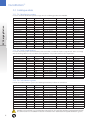
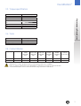
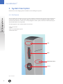
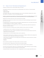
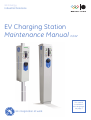
GE Energy
Industrial Solutions
EV Charging Station
Maintenance Manual Ed.02
This manual
is available in
more languages.
See page 2
GE imagination at work
DuraStation™
EV Charging Station
More Languages
FRANÇAIS
Vous pouvez télécharger le manuel d’entretien:
www.ge.com/fr/industrialsolutions
www.ge.com/be/industrialsolutions
Vous pouvez commander un exemplaire
sur papier par le code 451127
ESPAÑOL
Descarga el Manual de Mantenimiento en:
www.ge.com/es/industrialsolutions
Puede solicitar la versión impresa
con el código 451125
ITALIANO
Il manuale di manutenzione può essere
scaricato da:
www.ge.com/it/industrialsolutions
La versione stampata è ordinabile
con codice 451128
PORTUGUÊS
O Manual de Manutenção pode ser descarregado em:
www.ge.com/pt/industrialsolutions
Está igualmente disponível em versão
papel. Para pedir exemplares,
utilize o código 451131
DEUTSCH
Die Wartungshandbuch kann hier
heruntergeladen werden:
www.ge.com/de/industrialsolutions
Die gedruckte Version können Sie mit
der Nr. 451122 bestellen.
NEDERLANDS
Voor de onderhoudshandleiding surf naar:
www.ge.com/nl/industrialsolutions
www.ge.com/be/industrialsolutions
Een gedrukt exemplaar kan besteld
worden met code 451129
SUOMEN
SVENSKA
Huolto-opas ovat ladattavissa:
www.ge.com/fi/industrialsolutions
Painettu versio on tilattavissa
tuotekoodilla 451126
Underhållshandbok can laddas ner på:
www.ge.com/fi/industrialsolutions
Tryckt version kan beställas
med produktkoden 451123
DANSK
Service og vedligeholdelses manual
kan downloaded’s:
www.ge.com/fi/industrialsolutions
Printet version kan bestilles med kode 451121
NORSK
ENGLISH
This Maintenance Manual can be downloaded:
www.ge.com/ex/industrialsolutions
www.ge.com/uk/industrialsolutions
Extra printed versions can be ordered
with code 451124
2
Vedlikeholdsmanual kan nedlastes fra:
www.ge.com/fi/industrialsolutions
Papirversjon kan bestilles med kode 451130
DuraStation™
EV Charging Station
Maintenance Procedures
Maintenance Manual Ed.02
INDEX
1.
Safety and Compliance. . . . . . . . . . . . . . . . . . . . . . . . . . . . . . . . . . . . . . . . . . . . . . . . . . . . . . 4
2.
Definition and Terms . . . . . . . . . . . . . . . . . . . . . . . . . . . . . . . . . . . . . . . . . . . . . . . . . . . . . . . 4
3.
Technical Data . . . . . . . . . . . . . . . . . . . . . . . . . . . . . . . . . . . . . . . . . . . . . . . . . . . . . . . . . . . 5
3.1.
Technical characteristics . . . . . . . . . . . . . . . . . . . . . . . . . . . . . . . . . . . . . . . . . . . . . . . . 5
3.2.
Catalogue data . . . . . . . . . . . . . . . . . . . . . . . . . . . . . . . . . . . . . . . . . . . . . . . . . . . . . . 6
3.2.1. TN-S distribution system . . . . . . . . . . . . . . . . . . . . . . . . . . . . . . . . . . . . . . . . . . . . . . 6
3.2.2. TN-S with surge arrestor . . . . . . . . . . . . . . . . . . . . . . . . . . . . . . . . . . . . . . . . . . . . . . 6
3.2.3. TN-C distribution system . . . . . . . . . . . . . . . . . . . . . . . . . . . . . . . . . . . . . . . . . . . . . . 6
4.
5.
6.
3.3.
Torque specification . . . . . . . . . . . . . . . . . . . . . . . . . . . . . . . . . . . . . . . . . . . . . . . . . . . 7
3.4.
Tools . . . . . . . . . . . . . . . . . . . . . . . . . . . . . . . . . . . . . . . . . . . . . . . . . . . . . . . . . . . . . 7
3.5.
Contact blocks . . . . . . . . . . . . . . . . . . . . . . . . . . . . . . . . . . . . . . . . . . . . . . . . . . . . . . . 7
System Description. . . . . . . . . . . . . . . . . . . . . . . . . . . . . . . . . . . . . . . . . . . . . . . . . . . . . . . . 8
4.1.
Enclosure . . . . . . . . . . . . . . . . . . . . . . . . . . . . . . . . . . . . . . . . . . . . . . . . . . . . . . . . . . 8
4.2.
Power circuit . . . . . . . . . . . . . . . . . . . . . . . . . . . . . . . . . . . . . . . . . . . . . . . . . . . . . . . . 9
4.3.
Network management . . . . . . . . . . . . . . . . . . . . . . . . . . . . . . . . . . . . . . . . . . . . . . . . . . 9
General Operations & Safety Requirements. . . . . . . . . . . . . . . . . . . . . . . . . . . . . . . . . . . . . . . . 10
5.1.
General maintenance requirements. . . . . . . . . . . . . . . . . . . . . . . . . . . . . . . . . . . . . . . . . 10
5.2.
Enclosure maintenance requirements . . . . . . . . . . . . . . . . . . . . . . . . . . . . . . . . . . . . . . . 10
5.3.
Power circuit maintenance requirements . . . . . . . . . . . . . . . . . . . . . . . . . . . . . . . . . . . . . 11
5.4.
Cable maintenance requirements . . . . . . . . . . . . . . . . . . . . . . . . . . . . . . . . . . . . . . . . . . 12
5.5.
Gaskets maintenance requirements. . . . . . . . . . . . . . . . . . . . . . . . . . . . . . . . . . . . . . . . . 12
Replacing Components. . . . . . . . . . . . . . . . . . . . . . . . . . . . . . . . . . . . . . . . . . . . . . . . . . . . . 13
6.1.
Controller PCB. . . . . . . . . . . . . . . . . . . . . . . . . . . . . . . . . . . . . . . . . . . . . . . . . . . . . . . 13
6.2.
Socket . . . . . . . . . . . . . . . . . . . . . . . . . . . . . . . . . . . . . . . . . . . . . . . . . . . . . . . . . . . 13
6.3.
LED . . . . . . . . . . . . . . . . . . . . . . . . . . . . . . . . . . . . . . . . . . . . . . . . . . . . . . . . . . . . . 15
6.4.
RFID . . . . . . . . . . . . . . . . . . . . . . . . . . . . . . . . . . . . . . . . . . . . . . . . . . . . . . . . . . . . . 17
6.5.
Gaskets. . . . . . . . . . . . . . . . . . . . . . . . . . . . . . . . . . . . . . . . . . . . . . . . . . . . . . . . . . . 18
6.6.
Cable glands and screw plugs . . . . . . . . . . . . . . . . . . . . . . . . . . . . . . . . . . . . . . . . . . . . 19
6.7.
EVSE kiosk . . . . . . . . . . . . . . . . . . . . . . . . . . . . . . . . . . . . . . . . . . . . . . . . . . . . . . . . 19
3
DuraStation™
1. Safety and Compliance
This document provides instructions to properly maintain and service the DuraStation products included in section
3.2. Catalogue data.
EV Charging Station
Once installing the DuraStation, you should review this manual carefully and consult with a licensed contractor,
licensed electrician, and trained installation expert to insure compliance with local building codes, climate conditions,
safety standards and wiring regulations.
Only a licensed contractor, and a licensed electrician in accordance with all local and national codes and standards
should perform the maintenance of the DuraStation.
Under no circumstances will compliance with the information in this maintenance manual relieve the user of his/her
responsibility to comply with all applicable codes, safety standards or wiring regulation.
Intent of this service manual is to lend a hand to maintenance personnel in diagnosing and repairing filed units; and
also, to assist in establishing when a suspicious behavior is not a failure.
2. Definition and Terms
• EV: Electrical Vehicle
• EVSE: Electric Vehicle Supply Equipment
• EV Charging station = Charging station = EVSE
• PE: Protective Earth
4
DuraStation™
3. Technical Data
DuraStation has a list of basic features that are upgradeable, resulting in a robust and reliable solution for the need
of EV charging infrastructure.
Maintenance Procedures
• The socket satisfies mode 3 charging standards, and is optionally equipped with an electromechanical interlock.
• LED light to display charger status:
Green= Station active
Blinking Green= Vehicle connected, but not charging
Amber= Charging
Red= Fault occurred
• Option for a Radio Frequency Identification (RFID) reader:
users will gain charging authorization by swiping RFID cards in front of the readers.
• Ethernet network offered for RFID authorization service.
• RFID software application registers usage of the EVSE enabling data collection and will also monitor status of
communication between RFID and DuraStation.
• Residual current protection and auto re-closure.
• Vehicle ground monitoring circuit.
• Single phase metering.
3.1. Technical Characteristics
IEC Compliant
Mode 3 per IEC 61851
Vehicle Interface
Type 2 connector per IEC 62196
Voltage and Current Rating
230VAC at 16A or 400VAC at 32A
AC Max. Charging Power Output**
22kW (400VAC at 32A)
3.6kW (230VAC at 16A)
AC Power Input
230VAC requiring only L1, N, and PE
400VAC requiring only L1, L2, L3, N and PE
Recommended Panel Breaker
Compact pedestal, Pole, Wall:
1x4-pole 40A , or 2-pole 20A breaker on dedicated circuit
Back-to-back pedestal:
2x4-pole 40A, or 2-pole 20A breaker on dedicated circuit
Ground Fault Protection
Internal 30mA RCD with auto re-closure
Cold Load Start
Random start up between 0 and 15 minutes for peak protection
Local Area Network
CAT5 Ethernet
Network Communication Protocol
TCP/IP
RFID Reader
ISO15693 and ISO14443 compliant
Standby Power
5W typical
Outdoor Rated
Enclosure IP54-IK10, socket outlet IP44
Safety Compliance
IEC 61851 and IEC 62196 compliant
CE Marking Certification
Low Voltage (2006/95/EG) and EMC Directive (2004/108EC).
Resistance against surges
IEC 61851 compliant
EMI Compliance
IEC 61851 compliant
Operating Temperature
-30°C to +50°C ambient
Operating Humidity
Up to 95% non-condensing
Approximate Shipping Weights
Compact pedestal: 30kg
Back-to-back pedestal: 45kg
Pole: 25kg
Wall: 25kg
Dimensions HxWxD (in mm)
Compact pedestal: 1300 x 275 x 200
Back-to-back pedestal: 1300 x 350 x 300
Pole: 800 x 237 x 200
Wall: 800 x 237 x 200
** The maximum available power consumption is determined by the DuraStation. The actual power consumption is
determined by the EV.
5
DuraStation™
3.2. Catalogue data
3.2.1. TN-S distribution system
For use in electrical distribution systems of type TN-S, the following products are available:
EV Charging Station
Cat No.
EVSPE16A1P1N
EVSPE32A3P1N
EVSPE16A1P2N
EVSPE32A3P2N
EVSPE16A1P1R
EVSPE32A3P1R
EVSPE16A1P2R
EVSPE32A3P2R
EVSWA16A1P1N
EVSWA32A3P1N
EVSWA16A1P1R
EVSWA32A3P1R
EVSPO16A1P1N
EVSPO32A3P1N
EVSPO16A1P1R
EVSPO32A3P1R
Ref. No.
450100
450101
450102
450103
450104
450105
450106
450107
450108
450109
450110
450111
450112
450113
450114
450115
Type
Pedestal
Pedestal
Pedestal
Pedestal
Pedestal
Pedestal
Pedestal
Pedestal
Wall
Wall
Wall
Wall
Pole
Pole
Pole
Pole
Max. Output
230V 16A 1 phase
400V 32A 3 phase
230V 16A 1 phase
400V 32A 3 phase
230V 16A 1 phase
400V 32A 3 phase
230V 16A 1 phase
400V 32A 3 phase
230V 16A 1 phase
400V 32A 3 phase
230V 16A 1 phase
400V 32A 3 phase
230V 16A 1 phase
400V 32A 3 phase
230V 16A 1 phase
400V 32A 3 phase
No. of Sockets
1
1
2
2
1
1
2
2
1
1
1
1
1
1
1
1
RFID
N
N
N
N
Y
Y
Y
Y
N
N
Y
Y
N
N
Y
Y
Integrated Meter
Single phase
Singe phase
Single phase
Single phase
Single phase
Single phase
Single phase
Single phase
Single phase
Single phase
Single phase
Single phase
Single phase
Single phase
Single phase
Single phase
3.2.2. TN-S with surge arrestor
In certain electrical systems the DuraStation power circuit has to include an impulse surge arrestor device to comply
with the local regulations or the conditions of the application. See products below for this requirement:
Cat No.
EVSPE16A1P1N-SA
EVSPE32A3P1N-SA
EVSPE16A1P2N-SA
EVSPE32A3P2N-SA
EVSPE16A1P1R-SA
EVSPE32A3P1R-SA
EVSPE16A1P2R-SA
EVSPE32A3P2R-SA
EVSWA16A1P1N-SA
EVSWA32A3P1N-SA
EVSWA16A1P1R-SA
EVSWA32A3P1R-SA
Ref. No.
450131
450133
450139
450141
450132
450134
450140
450142
450135
450137
450136
450138
Type
Pedestal
Pedestal
Pedestal
Pedestal
Pedestal
Pedestal
Pedestal
Pedestal
Wall
Wall
Wall
Wall
Max. Output
230V 16A 1 phase
400V 32A 3 phase
230V 16A 1 phase
400V 32A 3 phase
230V 16A 1 phase
400V 32A 3 phase
230V 16A 1 phase
400V 32A 3 phase
230V 16A 1 phase
400V 32A 3 phase
230V 16A 1 phase
400V 32A 3 phase
No. of Sockets
1
1
2
2
1
1
2
2
1
1
1
1
RFID
N
N
N
N
Y
Y
Y
Y
N
N
Y
Y
Integrated Meter
Single phase
Singe phase
Single phase
Single phase
Single phase
Single phase
Single phase
Single phase
Single phase
Single phase
Single phase
Single phase
RFID
N
N
N
N
Y
Y
Y
Y
N
N
Y
Y
Integrated Meter
Single phase
Singe phase
Single phase
Single phase
Single phase
Single phase
Single phase
Single phase
Single phase
Single phase
Single phase
Single phase
3.2.3. TN-C distribution system
In TN-C electrical distribution systems, the following DuraStation products are considered:
Cat No.
EVSPE16A1P1N-NC
EVSPE32A3P1N-NC
EVSPE16A1P2N-NC
EVSPE32A3P2N-NC
EVSPE16A1P1R-NC
EVSPE32A3P1R-NC
EVSPE16A1P2R-NC
EVSPE32A3P2R-NC
EVSWA16A1P1N-NC
EVSWA32A3P1N-NC
EVSWA16A1P1R-NC
EVSWA32A3P1R-NC
Ref. No.
450143
450145
450151
450153
450144
450146
450152
450154
450147
450149
450148
450150
Type
Pedestal
Pedestal
Pedestal
Pedestal
Pedestal
Pedestal
Pedestal
Pedestal
Wall
Wall
Wall
Wall
Max. Output
230V 16A 1 phase
400V 32A 3 phase
230V 16A 1 phase
400V 32A 3 phase
230V 16A 1 phase
400V 32A 3 phase
230V 16A 1 phase
400V 32A 3 phase
230V 16A 1 phase
400V 32A 3 phase
230V 16A 1 phase
400V 32A 3 phase
No. of Sockets
1
1
2
2
1
1
2
2
1
1
1
1
CAUTION: In TN-C Networks, ensure that all earth connections are the same point, and also neutral and earth functions
are combined. Refer to “Installation Instruction” manual for more details about wiring and distribution systems.
6
DuraStation™
3.3. Torque specification
Size
Recommended Torque (N.m)
LED
0.5
M3
2.1
M4
RFID reader
1.2
M4
Connector (recommended by supplier Mennekes)
1.2
M5
Maintenance Procedures
M5
1.4
3.4. Tools
Type
Characteristics
Screwdriver
Used in wiring connections
Hexagonal key
Socket size: 19mm
Wire stripper
3.5. Contact blocks
Type range
Size
1 Single wire
(solid)
(min-max)
mm2
1 Single wire
(semi-solid)
(min-max)
mm2
2 Single wires
(semi-solid)
(min-max)
mm2
1 Stranded
(flexible)
(min-max)
mm2
2 Stranded
(flexible)
(min-max)
mm2
Rated
conductor
cross-section
RK 35 (Phases)
M6
2.5-16
2.5-50
16-16
2.5-35
2.5-16
35
SL 35 (Earthing)
M6
2.5-16
2.5-50
16-16
2.5-35
2.5-16
35
WARNING: De-energize equipment before performing any work on the installation.
Make sure that the main breaker of the DuraStation is locked out, as well as the upstream breaker
in the distribution panel. (This is achieved with accessory KS 644929 in both cases)
7
DuraStation™
4. System Description
Maintenance for the charging station is divided into the following sub-systems:
4.1. Enclosure
EV Charging Station
The surrounding case provides protection to personnel against incidental contact with the enclosed equipment
or parts that involve risk. It also provides a degree of protection to the enclosed equipment against specified
environmental conditions or reduces the risk of propagation of flame, sparks, and molten metal initiated by an
electrical disturbance occurring within.
The following devices are contained within the enclosure:
• LED: User interface
• Socket
• RFID: User identification system
• Maintenance door
LED
RFID
Maintenance door
Socket
Figure 1: Enclosure
8
DuraStation™
4.2. Power Circuit
Group of devices arranged in such a way that will protect the system from overcurrents, short-circuits, electric shock,
reinforcing insulation or conducting potential fault and residual currents to earthed point.
Maintenance Procedures
• Contactor
• MCB (Miniature Circuit Breaker)
• RCD (Residual Current Device; earth leakage detection)
• Tele MP (reconnection device)
Controller PCB
RCD
Tele MP
Contactor
MCB
Contact blocks
Figure 2: Power Circuit
4.3. Network management
Keeps track of resources in the network, how they are assigned and their availability so as to provide users
with a more efficient charging process. Refer to “Installation Instructions” manual for more details.
9
DuraStation™
5.
General Operations & Safety Requirements
EV Charging Station
Before Inspection or any maintenance work is done, be sure that all electrical power is disconnected.
Make sure that the main breaker of the DuraStation is locked out, as well as the upstream breaker in
the distribution panel. (This is achieved with accessory KS 644929 in both cases)
5.1. General Maintenance Requirements
Periodic maintenance must be established in order to obtain the best service from the EVSE charger.
An annual check of the switchgear devices and all connections should be the minimum requirement.
Equipment subject to highly repetitive operation may require more frequent maintenance.
A permanent record of all maintenance work should be kept. The record should include a list of periodic
checks and tests made, the date they were made, the condition of the equipment, and any repairs or
adjustments that were performed.
Maintenance employees must follow all recognized safety practices, such as those contained in the
National Electric Safety Code and in company or other safety regulations.
For specific information regarding the maintenance of devices, such as circuit breakers, RCD, relays,
meters, etc.. refer to the separate instruction book provided for each device.
5.2. Enclosure Maintenance Requirements
The enclosure station requires no maintenance other than occasional cleaning.
Warning: To reduce the risk of electrical shock or equipment damage, do not allow opening the unit while
cleaning it. Enclosure maintenance is performed only externally.
Clean the enclosure using a soft cloth lightly moistened with mild detergent solution.
Never use any type of abrasive pad, scouring powder, or flammable solvents such as alcohol or benzene.
10
DuraStation™
5.3. Power Circuit Maintenance Requirements
Inspection of the power circuit is recommended at least once a month.
• MCB, RCD, Tele MP
If the breaker remains open or closed for a long period of time, it is recommended that arrangements be made to
open and close it several times in succession, preferably under load.
At all times, it is important not to permit paint, oil or other foreign materials to remain on the insulating surfaces or the breaker
as they may cause low resistance between points of different potential and result in eventual electrical breakdown.
Always inspect the devices after a short circuit current has been interrupted.
Normally, the over current protective device on the circuit will prevent any electrical damage except at the actual
point of the short circuit.
Maintenance Procedures
More frequent inspections are recommended, if several load conditions, dust, moisture, or other unfavourable
conditions exist.
A thorough inspection of the entire system must be made after any large fault current to insure that there has been
no mechanical damage to conductors, insulation, or equipment.
Do not open sealed devices such as breaker trip units. If there is any possibility that sealed units may have been
damaged, they should be replaced.
At the time of inspection, the following checks should be made after the device has been de-energized.
- Manually operate the device several times checking for obstructions or excessive friction.
- Electrically operate the device several times (if breaker has electrical control) to ascertain whether the electrical
attachments are functioning properly.
- Break-age of parts or extensive burning will indicate need for replacement.
- Check operation of tripping devices, including over current trip devices, making sure all have positive tripping action.
(Discernible movement in tripping direction beyond point of tripping).
- Push test-button in the RCD device: positive tripping action (ensure RCD device is powered, therefor the contactor
should be closed manually).
• Contactor
Ensure a trouble free operation of the contactor until the next service is required.
As in the previous devices, always inspect the device after main breaker tripping.
At the same time, observations can be made to judge if the contactor operates well in the application.
Ensure that electrical continuity in all the poles is retained and should be operable in ON/trio/rest sequence manually.
If there is any possibility the unit has been damaged, it should be replaced.
For additional details on the particular device, refer to the applicable instruction manual provided with the device.
11
DuraStation™
• Impulse Surge Arrester (Refer to section 3.2.2)
The surge arresters do not contain wearing parts and therefor, they are maintenance free.
Replacement parts are not needed.
Maintenance is based into a visual inspection of the following parts:
Blank
Fault indicator
Red
EV Charging Station
- Check that the arrester housing is clean and free from where is installed.
- The monitoring device for leakage current (Fault indicator) is reviewed as it is indicated.
OK
replace
It is recommended to replace the units that caused the mechanically defect of the surge arrester.
5.4. Cable Maintenance Requirements
Inspect and check the cables as follows:
• Inspect all power cable connections for signs of overheating and tighten all connections.
• If severe discoloration or if damage is apparent, remove the damaged cable and replace any device
with damaged terminal.
CAUTION: Be sure the condition which caused the over heating has been corrected before reenergizing.
• Check the neutral bus and earth bus connection and mounting bolts for tightness.
• Check that all wiring connections are tight and all control cabling is intact.
5.5. Gaskets Maintenance Requirements
Gaskets require regular maintenance to prevent mold and mildew and to maintain the elasticity of the seal.
Visually check the different gaskets or lid for tears or punctures. Leaks are indicated by a streak of frost that forms
at the point of gasket failure.
Gasket and retainer groove cleaning can be accomplished with the use of warm soapy water and a soft bristle brush.
CAUTION: Avoid full strength cleaning products on gaskets as this can cause them to become brittle and prevent
proper sealing. Never use sharp tools or knives to scrape or clean the gasket. This could tear the gaskets.
12
DuraStation™
6. Replacing Components
Before Inspection or any maintenance work is done, be sure that all electrical power is disconnected.
Make sure that the main breaker of the DuraStation is locked out, as well as the upstream breaker in
the distribution panel. (This is achieved with accessory KS 644929 in both cases)
Maintenance Procedures
6.1. Controller PCB
Turn circuit breaker off, verifying no power
is applied. Open the enclosure door with
its corresponding key. Remove the door
carefully for improved access.
The different connectors included in
the controller are disconnected.
(See connectors in blue in
following picture)
Figure 3: Controller PCB
The four click supports that hold the controller are removed by pressing them.
The broken PCB needs to be replaced by the new one.
The new PCB is fixed to the enclosure in the same way, and all the connectors are installed again.
Note: DuraStation charger configuration will be necessary for this new PCB. Please, follow the described steps in the
provided “Charging Station Installation Instructions” manual.
6.2. Socket
Turn the circuit breaker off, verifying no power is applied.
Open the enclosure door with its corresponding key. Remove the door carefully for improved access.
Uninstall the connector from the enclosure as is indicated:
1. Inside the enclosure, remove the interlock part from the connector (for this, unscrew the two screws as indicated in
pictures below).
Figure 4: Removing interlock - STEP 1: unscrew
Figure 4: Removing interlock - STEP 2: remove
Figure 5: Connector without interlock
13
DuraStation™
EV Charging Station
2. Then, unscrew the four screws that hold the socket in the enclosure. (See the following picture to distinguish the
different parts of the connector).
Figure 6: Socket assembly
3. Disconnect the different cables from the broken connector.
4. Replace the socket with the new one and connect the cables again.
(Attention: Be sure to connect the cables correctly. See the below figure).
Lock
Proximity pilot (PP)
Control pilot (CP)
L1
N
L2
L3
Earth
Figure 7: Cables disposition
5. Finally fasten the connector again in the enclosure as indicated in step 2, and install the interlock as in the first
step. (Attention: Do not over-tighten. Consider recommended torques in section 3.3. Torque specification),
6. Close the door and lock it.
14
DuraStation™
6.3. LED
Turn the circuit breaker off and verify that no power is applied.
Open the enclosure door with its corresponding key. Remove the door carefully for improved access.
Uninstall the LED assembly from the enclosure as indicated in the following steps:
Maintenance Procedures
Figure 8: LED assembly
1. Disconnect the LED connector from the controller PCB (J15).
Figure 9: Controller PCB
2. Then, unscrew the four screws located inside the enclosure, that hold the LED metallic support in the charger.
Figure 10: LED assembly
15
DuraStation™
EV Charging Station
3. Once the LED frame is out of the enclosure. The following steps are applied: The LED strip is included in the frame
as shown, secured by internal screws. Replace the LED strip with a new one and secure it in the same way in the
given frame.
Figure 11: LED metallic support
4. Install the metallic support again into the enclosure as indicated in the following picture.
(Attention: Do not over-tighten. Consider recommended torques noted in section 3.3. Torque specification).
5. Connect again the LED connector to the controller-PCB (J15) as in the first step.
6. Once completed, close and lock the door of the enclosure.
16
DuraStation™
6.4. RFID
Turn the circuit breaker off and verify that no power is applied.
Open the enclosure door with its corresponding key. Remove the door carefully for improved access.
Uninstall the RFID assembly from the enclosure as indicated in the following steps:
Maintenance Procedures
1. Disconnect the RFID connector from the controller-PCB.
Figure 12: Controller PCB
2. The cable of the card reader includes a ferrite. Remove the ferrite carefully, for that, introduce the connector two
times through it as shown.
3. Unscrew the two screws located inside the enclosure, as it is shown in the following picture:
Figure 13: RFID assembly
4. Carefully remove the old RFID reader located in the front of the Durastation.
17
DuraStation™
EV Charging Station
5. Open the old RFID reader by unscrewing the screw at the bottom, as shown below.
6. In the old RFID reader, remove the internal mounting piece, where two axles are welded, as shown in the following
picture.
Figure 14: RFID assembly
7. In the same order, place this mounting part in the new RFID sensor and replace the RFID reader in the enclosure.
Attention: The cable of the card reader includes a ferrite. Ensure it is included in the new RFID with 2 turns in the
cable as indicated in step 2.
8. Fasten the RFID reader in the enclosure as indicated in the step 1, screwing the two screws inside the enclosure.
(Attention: Do not over-tighten. Consider recommended torques noted in section 3.3. Torque specification).
9. Connect again the RFID connector to the controller-PCB as in the first step.
10. Once completed, close and lock the door of the enclosure.
6.5. Gaskets
Gaskets are easily replaced and do not require the use of specific tools.
The gaskets can be pulled out of the groove in the door and new or clean gaskets can be pressed back into place.
Figure 15: Door gaskets
18
DuraStation™
6.6. Cable Glands and Screw Plugs
Cable Glands
In “Wall mounted” and “Pole mounted” DuraStation versions, the power supply cables are ensured by using cable glands.
They are easily replaced as indicated in the following steps:
Maintenance Procedures
1. Unscrew the external part of the cable gland, so it is removed completely.
2. Twist the inside part of the cable gland off, until it is removed (cables are loose).
Then, remove the internal part that supports the cables.
3. Replace the damaged cable gland by a new one, following the same previous steps.
Ensure to center the cables and turn the gland, until there is no possible cable movement.
Screw Plugs
In “Wall mounted” and “Pole mounted” DuraStation versions, if the DuraStation charger is not connected in series
with a second DuraStation, a screw plug is used to close the additional outlet in the back side of the DuraStation.
Therefor, the appropriate IP protection rating of the system (IP54) is maintained.
As for cable glands, they are easily replaced as indicated in the following steps:
1. Unscrew the external
part of the screw plug
until it is removed
completely.
2. Remove the internal
part and replace the
screw plug, by a new one,
following the same steps.
6.7. EVSE Kiosk
If the EVSE kiosk has suffered external damage, and as such affecting the IP protection rating of the system (IP 54),
the following parts of the EVSE kiosk should be inspected for any damage:
• Tampering lock
• Maintenance door
If any of these components have suffered any damage, the maintenance door should be replaced.
• Damage to the inside of the enclosure.
If you have any doubt about the correct IP protection rating in the EVSE kiosk, the entire EVSE kiosk must be replaced.
19
103977
GE Energy
Industrial Solutions
Belgium
GE Industrial Belgium
Nieuwevaart 51
B-9000 Gent
Tel. +32 (0)9 265 21 11
Finland
GE Energy Industrial Solutions
Kuortaneenkatu 2
FI-00510 Helsinki
Tel. +358 (0)10 394 3760
France
GE Energy Industrial Solutions
Paris Nord 2
13, rue de la Perdrix
F-95958 Roissy CDG Cédex
Tel. +33 (0)800 912 816
Germany
GE Energy Industrial Solutions
Vor den Siebenburgen 2
D-50676 Köln
Tel. +49 (0)221 16539 - 0
Hungary
GE Hungary Kft .
Vaci ut 81-83
H-1139 Budapest
Tel. +36 1 447 6050
Italy
GE Energy Industrial Solutions
Centro Direzionale Colleoni
Via Paracelso 16
Palazzo Andromeda B1
I-20041 Agrate Brianza (MB)
Tel. +39 2 61 773 1
Netherlands
GE Energy Industrial Solutions
Parallelweg 10
Nl-7482 CA Haaksbergen
Tel. +31 (0)53 573 03 03
Poland
GE Power Controls
Ul. Odrowaza 15
03-310 Warszawa
Tel. +48 22 519 76 00
Portugal
GE Energy Industrial Solutions
Rua Camilo Castelo Branco, 805
Apartado 2770
4401-601 Vila Nova de Gaia
Tel. +351 22 374 60 00
Russia
GE Energy Industrial Solutions
27/8, Electrozavodskaya street
Moscow, 107023
Tel. +7 495 937 11 11
South Africa
GE Energy Industrial Solutions
Unit 4, 130 Gazelle Avenue
Corporate Park Midrand 1685
P.O. Box 76672 Wendywood 2144
Tel. +27 11 238 3000
Spain
GE Energy Industrial Solutions
P.I. Clot del Tufau, s/n
E-08295 Sant Vicenç de Castellet
Tel. +34 900 993 625
United Arab Emirates
GE Energy Industrial Solutions
1101, City Tower 2, Sheikh Zayed Road
P.O. Box 11549, Dubai
Tel. +971 43131202
United Kingdom
GE Energy Industrial Solutions
Houghton Centre
Salthouse Road
Blackmills
Northampton
NN4 7EX
Tel. +44 (0)800 587 1239
@
www.ge.com/ex/industrialsolutions
www.ge.com/uk/industrialsolutions
GE imagination at work
Ref. E/5410/E/EX 1.0 Ed. 01/12
© Copyright GE Industrial Solutions 2012