1
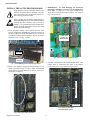
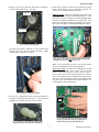
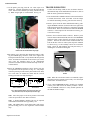
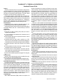
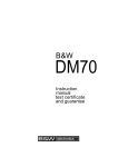
Superterm Accelerator ™
Plug-In Processor / Memory / Ethernet
Expansion for the Continental Superterm
and Sensormatic Sensorpanel II™
Model CICP18ACCBD
Installation and Service Manual
A NAPCO SECURITY GROUP COMPANY
355 Bayview Avenue, Amityville, NY 11701
Telephone: 631-842-9400
Fax: 631-842-9135
www.cicaccess.com
Publicly traded on NASDAQ
© NAPCO 2007
Symbol: NSSC
WI1593.15 6/07
1
Superterm Accelerator
FCC Warning
Changes or modifications to this unit not expressly approved by the party responsible for compliance could void the user’s authority to operate the equipment.
NOTE
This equipment has been tested and found to comply with the limits for a Class A digital device, pursuant to Part 15 of the FCC
Rules. These limits are designed to provide reasonable protection against harmful interference when the equipment is operated in
a commercial environment. This equipment generates, uses, and can radiate radio frequency energy and, if not installed and used
in accordance with the instruction manual, may cause harmful interference to radio communications. Operation of this equipment in a residential area is likely to cause harmful interference in which the user will be required to correct the interference at
his own expense.
Shielded cables must be used with this unit to ensure compliance with the Class A FCC limits.
DISCLAIMER
Continental Access makes no representations or warranties with respect to the contents hereof and specifically disclaims any implied warranties of merchantability or fitness for any particular purpose. Further, Continental Access reserves the right to revise
this publication and to make changes from time to time in the content hereof without obligation of Continental Access to notify
any person of such revision or changes.
Information furnished by Continental Access is believed to be accurate and reliable. However, no responsibility is assumed by
Continental Access for its use; nor for any infringements of other rights of third parties which may result from its use. No license
is granted by implications or otherwise under any patent or patent rights of Continental Access.
Sensorpanel II is a registered Trademark of Sensormatic Electronics Corporation.
Copyright © 2007 by Continental Access. All rights reserved. No part of this publication may be reproduced, transmitted, transcribed, or stored in a retrieval system, without the prior written permission of Continental Access,
355 Bayview Avenue, Amityville, NY 11701. 631-842-9400
A NAPCO SECURITY GROUP COMPANY
Superterm Accelerator
2
THE INSTALLATION OF THIS PRODUCT SHOULD BE MADE BY QUALIFIED
SERVICE PERSONNEL AND SHOULD CONFORM TO ALL LOCAL CODES.
The lightning flash with arrowhead
symbol, within an equilateral triangle, is intended to alert the user to
the
presence
of
uninsulated
'dangerous voltage' within the product's enclosure that may be of sufficient magnitude to constitute a risk
of electric shock to persons.
CAUTION
RISK OF ELECTRIC SHOCK
DO NOT OPEN
CAUTION: TO REDUCE THE RISK OF ELECTRIC SHOCK
DO NOT REMOVE COVERS (OR BACK).
The exclamation point within an
equilateral triangle is intended to
alert the user to the presence of important operating and maintenance
(servicing) instructions in the literature accompanying the product.
NO USER-SERVICEABLE PARTS INSIDE
REFER SERVICING TO QUALIFIED SERVICE PERSONNEL
WARNING
UNPACKING AND INSPECTION
Unpack carefully. This is an electronic product and should be handled as such. Compare the items received with the packing list
with your order.
This product generates, uses, and can radiate
radio frequency energy and if not installed and
used in accordance with the instruction manual,
may cause interference to radio communications. It has been tested and found to comply
with the limits for a Class A computing device
pursuant to Part 15 of FCC Rules, which are designed to provide reasonable protection against
such interference when operated in a commercial environment. Operation of this product in a
residential area is likely to cause interference in
which case the user at his own expense will be
required to take whatever measures may be required to correct the interference.
BE SURE TO SAVE THE SHIPPING CARTONS
AND INSERT PIECES. THEY ARE THE SAFEST
MATERIAL IN WHICH TO MAKE FUTURE SHIPMENTS OF THE PRODUCT.
MAINTENANCE
WARNING
User maintenance of this unit is limited to external cleaning and inspection.
TO REDUCE THE RISK OF FIRE OR SHOCK HAZARD, DO
NOT EXPOSE THIS PRODUCT TO RAIN OR MOISTURE.
3
Superterm Accelerator
TABLE OF CONTENTS
DESCRIPTION ..................................................................................................................................... 5
BEFORE INSTALLATION .................................................................................................................. 5
ABOUT THIS MANUAL ..................................................................................................................... 5
End-User Periodic Tests and Emergency Planning ............................................................................. 5
INSTALLATION .................................................................................................................................. 6
Plugging in the Accelerator Board ...................................................................................................... 6
TROUBLESHOOTING ........................................................................................................................ 8
SUPERTERM ACCELERATOR COMPONENTS.............................................................................. 9
ACCESSORIES & SPECIFICATIONS .............................................................................................. 10
Model Numbers ............................................................................................................................................10
Specifications ...............................................................................................................................................10
Maximum Recommended Cable Length .....................................................................................................10
WARRANTY ....................................................................................................................................... 11
Superterm Accelerator
4
DESCRIPTION
DESCRIPTION
Only qualified service personnel familiar with all local building codes
should attempt this installation. Take appropriate safeguards to avoid
unintentional operation by employees and maintenance personnel
working about the premises.
™
The Superterm Accelerator adds wide-band Ethernet connectivity,
greater memory capacity and higher speed processing to new and existing Sensorpanel II and Superterm installations. Existing installations may be upgraded with minimal rework at the facility. All field
wiring for the Card Readers, Electrical Locks, Alarm and Accessory
Relay circuits remain intact.
The main control panel is categorized as PERMANENTLY CONNECTED EQUIPMENT with fixed wiring. This system must be
installed within the protected premise in accordance with the National
Electrical Code (NFPA70), local codes, and the authorities having
jurisdiction.
The main benefits of the Superterm Accelerator are greater cardholder
capacity to support the needs of a growing facility and much faster
database downloads to complete these larger downloads in less time.
A Ground Bond Strap is bolted between the Enclosure and the Door
to reduce the risk of electric shock. If the Ground Bond Strap is unbolted from the Door to allow the Door to be removed, it is critical
that the Ground Bond Strap be correctly attached before putting the
Access Control Unit into service.
The larger capacity makes the Accelerator-equipped Superterm the
preferred platform for emerging large badge formats such as
FIPS201, PIV and TWIC.
MIS costs associated with the use of Ethernet cables are minimized
because the existing EIA/RS-422 Repeater Network Wiring may continue to be used to link panels together. Thus, one Ethernet cable may
serve as many as 63 Access Control Panels that are equipped with the
Superterm Accelerator.
The warnings listed below are designed for the safety of the install/
service technician and for the continued proper function of the unit.
ABOUT THIS MANUAL
This manual describes the installation of the Superterm Accelerator
board.
Other communication configurations exist, including direct Ethernet
connection to each panel, high-speed EIA/RS-422 connections (460.8
KBaud), and even a high-speed EIA/RS-232 (921.6 KBaud) connection. See Communications Options, publication # WI1617.
End-User Periodic Tests and Emergency Planning
The Host Computer Software supervises the Access Control System,
reporting failures at an individual panel within seconds of the occurrence. Nevertheless, failures can occur at the Door Sense and Bypass
contact monitoring hardware, the individual Card Reader electronics
and wiring, or the Electric Door Lock Hardware that will not be detected until the equipment is used. For this reason, please instruct
staff at the installation to perform a "walk through" test at every controlled entrance and verify operation of all the monitored contacts at
least once per week, especially at sites that are less frequently used.
Assist the Security Staff at the installation to devise acceptable alternates to allow entrance and monitoring of access at controlled sites
impacted by equipment failures, especially in high-traffic areas.
The Accelerator Board may be installed in the following equipment:
•
•
•
Superterm
Turbo Superterm
Sensorpanel II™
All Models
All Models
All Models
Note: Sensorpanel II is a registered Trademark of Sensormatic Electronics Corporation.
CA3000 - Software Release 2.51 or later is required.
BEFORE INSTALLATION
Before installing the Accelerator PC board, be sure the existing
control panel is working properly. Once an individual panel has
been tested and found operating satisfactorily, it can then be safely
upgraded by the installation of the Accelerator board.
Provide staff members at the facility with contact information that
will help assure the swift correction of equipment outages.
CAUTION
Prevent the risk of a fire by replacing ALL
fuses with the same type and rating. The
main fuse protects the power supply circuit
against excessive currents and short circuits. Failure of the power supply (other
than a blown fuse) usually indicates a fault
in a power supply component. There are
no user-serviceable parts in the panel cabinet. Replace the power supply if it fails.
Warnings indicate that a particular process
exposes the installer to live circuits or that
making wrong connections can lead to
equipment failure.
WARNING
The lower part of the power supply has exposed terminals and components (see page
10). DO NOT probe the power supply and
expose yourself to high voltage and a shock
hazard.
Do not place accessory circuit cables in the
same conduit sections containing power
cables.
WARNING
The risk of a serious electrical shock exists
if the wiring harness power connector is
removed from the Super Two circuit board,
but AC power remains live at the AC Input
Terminal Block (see Figure 7, page 15).
NOTES:
Notes are included with a procedure informing the installer about related material.
CAUTION
Cautions indicate that a particular process
requires special attention.
WARNING
CAUTION
5
Superterm Accelerator
INSTALLATION
INSTALL THE ACCELERATOR BOARD
Keep the black protective antistatic foam in place
until the Accelerator PCB is installed. The antistatic foam protects the 40-pin header on the bottom of the Accelerator PC board.
3. IMPORTANT: To avoid damaging the Accelerator
board pins, remember to remove U37, the 40-pin processor chip. Location U37 is the 40-pin receptacle into
which the Accelerator PCB will be placed. See image in
Fig. 3 for the location.
Prior to opening the Accelerator PCB package or
touching anything inside the control panel enclosure,
discharge any static electricity from your body or
clothing. Use a grounded wrist strap or touch an unpainted, grounded metal object such as the metal
frame of the panel enclosure.
1. Inside the panel housing, remove power from the main
PCB by pushing the POWER plug connector (located on
the lower right of the PCB) downward until the connector
is completely separated from the PCB. Do not disconnect
the battery wires. See Fig. 1, below.
Location of U37
processor chip.
Remove this chip.
Power socket
Fig. 3: Remove the processor chip located in "U37".
Power plug
Fig. 1: Push POWER plug connector downward until removed.
Empty 40-pin receptacle at U37
2. Remove any Memory Expansion Boards located in U55
and/or U56 (circled in Fig. 2, below). Note: The EPROM
(U39) and the on-board SRAM (U61) may be removed or
left in place, as desired.
4. Carefully cut and remove the resistor labeled "R62". This
resistor "R62" is located near the center of the motherboard, just left of "U37" as shown in Fig. 4, below.
Location of R62
Fig. 4: Location of resistor "R62".
This resistor MUST be removed.
Fig. 2: Empty location "U56" (circled above).
Superterm Accelerator
6
INSTALLATION
7. Remove the protective black foam pad from the 40-pin
header on the bottom of the Accelerator PC board. Be
careful--pins are delicate and are easily bent.
5. Remove any screws or fasteners from the 6-32 threads located near HS3 (heat sink #3). See Fig. 5 .
6-32 threads
8. Align the board: Hold the Accelerator PC board with its left
side angled slightly closer to the motherboard (Fig. 8). Gently place the two left Accelerator PC board mounting holes
over the two snap-lock standoffs (do not insert fully). Then
place the lower-right Accelerator mounting hole over the
brass insert of the male-to-male standoff (do not insert fully).
Heat Sink #3
Fig. 5: Location of threads near HS3.
Into these 6-32 threads, install the ¾" nylon male-to-male
standoff with brass inserts (threads) provided. Note:
"Finger tight" is sufficient. See Fig. 6.
Fig. 8: Arrows indicate location of the two left Accelerator PC Board
mounting holes. Place holes over the two snap-lock standoffs before
placing over male-to-male standoff--do not insert yet.
Note: Two viewing holes (see Fig. 9 for locations) allow
the use of a flashlight to check the pin alignment.
Insert the board: With all three mounting holes placed
over all three standoffs, place fingers over the 40-pin
header on the Accelerator PC board as shown in Fig. 9.
Press evenly between the two 40-pin header rows with fingers of your right hand while simultaneously applying pressure over the two left mounting holes until the board snaps
into place. Press more firmly over the 40-pin header to verify the header is fully seated in place.
Fig. 6: Install the ¾" male-to-male standoff.
6. Find the two existing white nylon snap-lock standoffs on
the upper-left of the PC board (see Fig. 7). Be sure they are
straight (these standoffs may have bent over time).
Viewing
Holes
Fig. 9: Press evenly between the two 40-pin header rows
with your right hand fingers while gently pressing over the
two left mounting holes. The board snaps into place.
Fig. 7: Photo of one of the two white nylon snap-lock
standoffs located at the upper-left of the PC motherboard.
7
Superterm Accelerator
INSTALLATION
9. In the plastic parts bag, find the 3/8" white nylon 6-32
thumb nut. Carefully thread this nut into the brass threads
of the male-to-male standoff (previously installed in step
5). Note: "Finger tight" is recommended. See Fig. 10.
TROUBLESHOOTING
If either the OK lamp (LED) on the Accelerator board or
the heartbeat lamp on the motherboard (location T1) fails to
blink in unison, perform the following:
1. Press and hold the red RESET button on the main board for
4 seconds, then release. Wait 10 seconds. If the two lamps
are still not functioning correctly, proceed to the next step.
2. Remove power from the main motherboard PCB by pushing the POWER connector (located on the lower right of the
PCB) downward until the connector is completely separated
from the PCB. Wait 10 seconds and reconnect the POWER
connector. If the lamps still do not function correctly, proceed to the next step.
3. Remove the Accelerator board as follows: Remove power
from the main motherboard PCB, then move the MEMORY
BACKUP CELL jumper from the IN position to the OUT
position. Remove the male-to-male standoff thumb nut.
Push in the tabs of the two white nylon snap-lock standoffs
as shown in Fig. 12 and carefully remove the Accelerator
board. Check for and straighten any bent pins and try reinstalling the Accelerator board again.
Fig. 10: Thread the thumb nut into the brass
threads of the male-to-male standoff "finger tight".
10. Re-connect power from the main Superterm PCB by pushing the POWER plug connector on the lower right of the
PCB upward into the PCB. Verify that the OK lamp (LED)
on the Accelerator board blinks on and off once per second.
Also verify the heartbeat lamp on the motherboard
(location T1) blinks in unison with the OK lamp on the Accelerator board.
PUSH IN TAB
10. Move the MEMORY BACKUP CELL jumper from the
OUT position to the IN position (see Fig. 11). The jumper
in the IN position provides memory data retention for about
two weeks after AC Mains has failed and the Gel-cell
backup power has been fully discharged.
Note: When the Accelerator board is not installed, replace
the black protective antistatic foam to fully cover the 40-pin
header of the Accelerator board.
IN
OUT
CLR
IN
OUT
CLR
"OUT" Position
Fig. 12: Push in tab to detach "snap lock" type
standoff.
"IN" Position
Fig. 11: Move the Memory Backup Cell jumper from the "OUT" posi-
4. If any CICP18MEM8MB memory modules are installed,
remove power and remove the memory modules. Reconnect the POWER connector to verify normal operation of
the OK and heartbeat lamps.
tion (shown above left) to the "IN" position (shown above right).
Note: Move the jumper to the OUT position if the board
will be un-powered for more than a few hours.
Note: A drained Memory Backup Cell may be replaced
with another Duracell DL2032 type battery cell.
Note: The lithium battery on the main PCB is still used to
provide backup power to the Superterm Clock/Calendar
chip.
Superterm Accelerator
8
COMPONENTS
SUPERTERM ACCELERATOR COMPONENTS
Mounting Holes – For the optional
Ethernet Interface or the EIA/RS-232
Interface.
Connector – For the optional Ethernet
Interface or the EIA/RS-232 Interface.
Lithium Coin Cell and Holder – Replace
drained cell with a Duracell DL2032.
Jumper Block – Place in OUT position
when board is not in service. Place to
IN position to maintain Database Memory during long-term power failures.
Expansion Memory Sockets – Each
Module adds 8MB of battery-backed
static RAM.
Rx – Receiving Data on Plug-in Ethernet
Port or High Speed EIA/RS-232 Channel.
Tx – Transmitting Data on High Speed
Port.
PWR – Receiving 5 Volt power from
OK – Flashes in unison with the “Heatbeat” Lamp
on the Panel during normal operation.
RST – Blinks on during Panel Reset. A steady
blink indicates Watchdog Timer activity.
9
Superterm Accelerator
ACCESSORIES & SPECIFICATIONS
ACCESSORIES
Description
Ethernet Module
Model Number
CICP18ACCNETBD
EIA/RS-232 Module
CICP18ACCEIABD
8 MB Memory Module CICP18MEM8MB
Comments
Adds 10/100Base-T Ethernet to Accelerator
Adds high-speed EIA/RS-232 to Accelerator
Note: Only one Ethernet or EIA/RS-232 Plug-in Board may be added to an Acceleration Board. Two 8 MB Memory Modules may
be added, to bring the total capacity to 20 MB.
The Superterm Plug-in Accelerator provides Processor/Memory/Network Enhancement for the following equipment:
Superterm
CICP1400UL
CICP1400ULExp
CICP1800
CICP1800Exp
Turbo Superterm
CICP1400TUL
CICP1400TULExp
CICP1800T
CICP1800TExp
Sensorpanel II1
1
CA3000 Version 2.51 or later is required.
Note: The Accelerator will not operate with Sensormatic® AC500 Software.
SPECIFICATIONS
•
•
•
•
32-Bit ARM7TDMI Processor running at 58.94 MHz
Program Code Memory held in 256KB FLASH Memory internal to the 32-bit processor
Base Memory 32-Bit wide 4MB on board for Database; Approximately 120,000 Cardholder capacity
Each plug-in 8MB Memory Expansion Module increases cardholder capacity by about 250,000 cards. With two modules,
approximately 600,000 cardholder capacity is available.
Note: The number of Badge Digits, Activity Links, Access Groups, and Transaction Buffer size required will influence the
total Cardholder Capacity.
Maximum Recommended Cable Length :
EIA/RS-232
Baud Rate
921.6KBaud
460.8KBaud
230.4KBaud
115.2KBaud
Practical EIA/RS-232 Distance Limits
10 Feet
20 Feet
40 Feet
80 Feet
EIA/RS-422
Baud Rate
460.8KBaud
230.4KBaud
115.2KBaud
Practical EIA/RS-422 Distance Limits (Between Panels)
1000 Feet
2000 Feet
4000 Feet
Ethernet
Speed
10/100Base-T
Superterm Accelerator
Limits defined by IEEE802.3 for
CAT5/6 Copper Cable (to Switch or Router)
100 Meters (305 Feet)
10
WARRANTY / TERMS & CONDITIONS
Standard Terms of Sale
Ordering
Orders for Continental products may be placed by calling Continental’s order department or by issuing a purchase order specifying the
quantity of Products, the desired delivery date, shipping method, and
the location to which product should be shipped. If an order is placed
by telephone, it must be confirmed in writing by fax or mail.
If the customer requests a guaranteed ship date or expedited shipping, Continental reserves the right to add to the price, with the customer’s approval, expenses which increase the cost of production and
delivery, i.e. freight charges, overtime expenses, etc. Continental reserves the right to change any price on this price list and all prices are
subject to factory reconfirmation at the time of placing an order.
Sales Assistance
Continental will furnish to customers, reasonable quantities of product-related catalogs and other sales and promotional literature.
Continental will provide customer training, both technical and sales at
Continentals facilities in New York. Contact the factory for costs and
requirements.
Payment Terms
• Sales terms are Cash on Delivery (COD) unless prior credit arrangements are established.
• If credit arrangements are established with Continental, terms of
sale are net 10 days.
• Interest charges shall accrue on all past due accounts at a rate of
1.5% per month (18% APR).
• Continental reserves the right to place a customer on a C.O.D.
status in the event that customer’s account becomes delinquent or
Continental becomes unsure about customer’s financial capabilities.
• Continental will charge a Service Fee of $50.00 for any returned
check.
• If customer believes an invoice to be in error, customer shall notify
Continental of the error within thirty (30) days.
• Continental reserves a security interest in all products sold hereunder, together with all proceeds thereof to secure the performance
of the customer’s obligations hereunder.
• All orders unless otherwise requested are shipped F.O.B. Amityville,
NY.
Cancelled Orders
Special or custom order items that cannot be cancelled with our suppliers are subject to a 100% cancellation charge.
No unauthorized, returned merchandise will be accepted for credit.
Orders returned or canceled are subject to a 25% restocking charge.
Return Material Authorizations
No products will be accepted for return to Continental without prior
written authorization (RMA). Unauthorized returns will not be accepted
from the carrier by the receiving department. The customer may request a return material authorization (RMA), whether for credit or repair
of the product. Continental will either issue an RMA or provide the customer with a written explanation for not issuing the RMA. Except for
warranty claims, no returns will be accepted more than 60 days after
shipment from Continental. Orders that are accepted for return are
subject to a 25% restocking charge. No product will be accepted for
return which has been special ordered or custom in nature.
Limited Warranty
Return Material Authorization (RMA) numbers are required to be
issued by Continental prior to returning any Product for service, repair,
credit or exchange. Continental warrants that its Products shall be free
from defects in materials and workmanship for a period of one year
from date of shipment of the product to purchaser. The warranty on 3rd
party equipment such as terminals, printers, and communications devices shall be 1 year from date of shipment. Remediation of this warranty shall be limited to the repair or replacement of those products
which are defective or become defective under normal use. Continental’s warranty shall not extend to any product which is found after examination to be defective as a result of misuse, improper storage, incorrect installation, operation or maintenance, alteration, modification or
accident.
There are no other warranties which extend beyond this provision.
This warranty is in lieu of all other warranties whether express, implied
or statutory, including implied warranties of merchantability or fitness for
any particular purpose. No representation or warranty of the distributor
shall extend the liability or responsibility of the manufacturer beyond the
terms of this provision. In no event shall Continental be liable for any
costs, loss of profits, loss of use, incidental, consequential or special
damages to any person resulting from the use of Continental’s products.
The above limited warranty is the only warranty provided by Continental. Continental makes no other warranties or guarantees, whether
expressed or implied, including, but not limited to, warranties and/or
guarantees of merchantability or fitness for a particular purpose. In no
event shall Continental be liable for any indirect, consequential or incidental damages, including those to person and those for lost wages, or
other economic loss.
Product Liability
Continental’s sole Liability and the customer's exclusive remedy for
damages, shall not exceed the cost of correcting the defect and in no
event shall such liability be greater than the purchase price paid by the
customer for the defective equipment or software. Under no Circumstances will Continental be liable for direct, indirect or consequential
damages of any kind.
General Notices:
In order to assure that Continental’s customers receive the most accurate and reliable information possible, Continental at times monitors
telephone calls
Information and pricing contained within this document are subject to
change without notice.
Continental does not recommend that these products be used as the
primary means of monitoring, warning or egress. Primary warning or
monitoring systems should always meet local fire and safety code requirements.
This transaction shall be governed and construed in accordance with
the laws of the State of New York.
Continental specifically rejects any terms or conditions stated by the
customer or contained within purchase documents or correspondence
from the customer which are in addition to, conflict with or limit, terms or
conditions set forth herein. The customer’s execution or other acceptance of this proposal or its acceptance of delivery of all or part of the
goods to be delivered hereunder shall constitute customer’s acceptance of the terms and conditions herein and shall be deemed to exclude any additional, conflicting or limiting terms stated by customer or
contained in customer’s purchase documents or correspondence.
11
Superterm Accelerator
A NAPCO SECURITY GROUP COMPANY
355 Bayview Avenue, Amityville, NY 11701
Phone: 631-842-9400 Fax: 631-842-9135
www.cicaccess.com
Publicly traded on NASDAQ
Superterm Accelerator
12
Symbol: NSSC